ac transformer.pdf
TRANSCRIPT

8/20/2019 ac transformer.pdf
http://slidepdf.com/reader/full/ac-transformerpdf 1/120
UC-NRLF
am
TRANSFORMERS.
W:
WEEKES.

8/20/2019 ac transformer.pdf
http://slidepdf.com/reader/full/ac-transformerpdf 2/120
J
nt_-n_-TL._
REESE
LIBRARY
UNIVERSITY
OF
CALIFORNIA.
jti^UL
.
i8u*
.
M>.
7/64^?
Q
aK
No.

8/20/2019 ac transformer.pdf
http://slidepdf.com/reader/full/ac-transformerpdf 3/120

8/20/2019 ac transformer.pdf
http://slidepdf.com/reader/full/ac-transformerpdf 4/120

8/20/2019 ac transformer.pdf
http://slidepdf.com/reader/full/ac-transformerpdf 5/120
ALTEKNATE-CUKKENT
TRANSFORMERS.

8/20/2019 ac transformer.pdf
http://slidepdf.com/reader/full/ac-transformerpdf 6/120

8/20/2019 ac transformer.pdf
http://slidepdf.com/reader/full/ac-transformerpdf 7/120
THE
DESIGN
OF
ALTERNATE-CURRENT
TRANSFORMERS.
R.
W.
WEEKES,
WHIT.SCH.,
Assoc.M.lNST.C.E.
ILLUSTRATED.
BIGGS AND
Co.,
139-140,
SALISBURY
COURT,
LONDON,
E.C
1893-

8/20/2019 ac transformer.pdf
http://slidepdf.com/reader/full/ac-transformerpdf 8/120

8/20/2019 ac transformer.pdf
http://slidepdf.com/reader/full/ac-transformerpdf 9/120
PREFACE
THE
invention
of
the
alternate-current
transformer
some
years
ago
led
to the introduction of
the
system
of
high-tension
distribution
of
electric
energy
for
lighting
purposes.
The
saving
in the
first
cost
of
the
copper
mains
being
the
chief
advantage
of
the
system
in the
eyes
of
the
promoters,
the
question
of the
efficiency
of this method
of
supply,
except
at
full
load,
was not
considered.
Now,
experience
has
shown
that
the
cost of
the
annual
supply
depends
largely
on
the
efficiency
of
the
transformers
used,
and that
the
loss
at
light
loads
is
the
most
important
factor
in
determining
this
cost.
Hence
the
design
of
alternate-current
transformers
needs
more
careful
attention
as
the
demand for
higher
efficiency
arises.
I
have
endeavoured in the
following
pages
to
describe
as
simply
as
possible
the
principles
involved
in the
construction
of transformers
on
economic
lines,
both
as
regards
first cost and
power
vyasted
when
working.
To
the formulas
deduced
from these
principles
I
have
added
several others
which
are
useful
when
determining
quickly
the
dimensions
of
the various circuits.
To
enable
more to
follow
the
reasoning,
higher
mathematics
have been
avoided,
although
this
omission has necessitated
the
acceptance
of certain well-known
formulae
without
proof.
The
examples
worked
out
and
illustrated
show
the
general pro-
cedure of
designing
transformers
of
different
types
to
fulfil
definite
conditions.
R.
W.
WEEKES.

8/20/2019 ac transformer.pdf
http://slidepdf.com/reader/full/ac-transformerpdf 10/120
CONTENTS.
PAGE.
Brown
-Boveri
Transformer
... ... ...
...
46
Circuit,
Iron
... ...
...
...
..
...
74,
77
Circuits,
Perimeter
of
...
...
...
21,
47, 49,
69
Circuits,
Size,
Copper
... ... ...
23, 50, 52,
53,
71
Conclusions
...
... ...
... ,.,
...
93
Condensers,
Use
with
Transformers
... ... ...
80
Cooling
Surface
..
...
...
..
22,
39,
57,
73
Copper
Circuit,
First
Design
...
...
..
...
30,
36
Copper
in
Circuits
23,50,52,53,71
Copper
Loss
13,38,56,67,73
Core
43,
59,
61, 65,
71, 75,
77
Design,
Long
Shell
Type,
Square
Core
... ..
29
Design,
Mordey
Type
...
... ...
... ...
47
Design,
Third
65
Designing,
Routine
in
...
...
..
...
...
25
Details,
First
Design
...
... ...
.. ...
37
Details,
Second
or
Mordey
Design
...
...
56
Details,
Third
Design
72
Early
Designs,
Faults
in
...
... ... ...
10
Efficiency
13,
28,
84
Efficiency
and
Frequency
...
...
... ...
84
Elwell-Parker
Transformer
...
... ...
... 62
E.M.F.
in
Coil
15
Faults
in
Early
Designs
...
... ...
... ...
10
Ferranti
Transformer
...
... ...
...
...
7
*
First
Design
...
.. ...
... ...
...
29
Fleming's
Table,
Transformers
Tested
1
1
Foucault
Currents
...
...
... ...
19,
21,
69
Frequency
...
...
...
..
25,
29,
84,
85
Frequency
and
Efficiency
... . .
...
...
84
Hedgehog
Transformer
... ... ...
..
..
76
Hysteresis
19,
20,
87,
91

8/20/2019 ac transformer.pdf
http://slidepdf.com/reader/full/ac-transformerpdf 11/120
CONTENTS.
PAGE
Induction
...
... ...
... ...
... ...
19,
86
Iron
Cores
... ...
... ... ...
.
43,
59
Iron
Loss
12,
20,
35,
49,
56,
66,
73,
79,
80,
89,.
90
Iron,
Quality
of
...
... ...
...
... ...
15
Joints,
Faced ...
...
...
...
...
...
45
Large
v.
Small
Transformers ...
...
...
...
8
1
Leakage,
Magnetic
...
...
... ...
.
...
24,
64
Magnetic
Leakage
...
... ...
...
24,
64,
81
Mordey
Type
Transformer
... ...
...
...
47
Oerlikon Transformer
...
... ...
...
...
44
Permeability
...
19,
2
5>
3
6
Power
Factor
...
...
... ...
...
...
20,
58
Principles
involved
...
... ...
...
...
14
Routine
in
Designing
...
... ...
...
...
25
Sine
Law
...
...
...
...
...
... ...
15
Stampings
..
..
...
...
...
...
48
Steinmetz
on
Hysteresis
...
..
...
... ...
20
Swinburne's Transformer
...
... ...
...
j6
Tests,
Fleming's
...
n
Transformer Formula
for
E.M.F.
... ...
...
16
Transformer
Loads ...
... ...
..
...
18
TRANSFORMERS
Brown-Boveri
...
...
... ... ...
46
for
Different Methods
of
Supply
... ...
94
Elementary
..
..
... ...
..
14
Elwell-Parker
62
Ferranti
...
... ... ...
...
7
1
Large
v.
Small
...
...
..
...
8
1
Law
of
...
..
... ... ...
...
15
Oerlikon ...
...
...
...
..
44
Table of
Tests
11
Westinghouse
...
...
... ... ...
61
Value
of
/j.
...
..
...
...
...
...
19
Voltage
16,
17
Westinghouse
Transformer
...
... ... ...
61
Windings,
Determination,
First
Design
... ...
30
Windings,
Mordey
Type
...
...
...
..
54
Wire,
First
Design
...
...
... ...
33,
34, 39

8/20/2019 ac transformer.pdf
http://slidepdf.com/reader/full/ac-transformerpdf 12/120

8/20/2019 ac transformer.pdf
http://slidepdf.com/reader/full/ac-transformerpdf 13/120
THE
DESIGN
OP
ALTERNATE
CURRENT
TRANSFORMERS,
The
reliable
information
available
on
the
subject
of
alternate-current
transformers has
until
recently
been
very
scanty.
When
the
high
tension
system
of
distribution,
with
transformers
in
parallel,
was
introduced some
eight
years
ago,
the
good
points
of
the
transformers
as then
made,
were much
exaggera-
ted.
It
was
generally
stated
that
the
efficiency
at
all
loads
was
very
high,
and
that
the current
taken
by
the
primary
when
no
lamps
were
on the
secondary
circuit
was
so
small
as
to be
almost
neligible.
The
last
statement
may
be
excused
to some
extent
when
it is
remembered that small
current
measurements
could not
be
made
so
readily
then.
Still,
the
engineers
in
charge
of
central
stations
have
found
that
the
small
currents
required
to
energise
each
transformer
soon
become
a
serious
item
in
the
cost
of
production.
In
consequence
of
their
experience
they
now
specify
what
the various
transformers
of
doing,
raising

8/20/2019 ac transformer.pdf
http://slidepdf.com/reader/full/ac-transformerpdf 14/120
io
The
Design
of
standard
of
their
requirements
induce
the
makers
to
make
further
improvements.
The
faults
existing
in
the
early
designs
of
trans-
formers
may
be
briefly
summarised as
follows
:
Bad
regulation,
that
is,
the
pressure
at the
secondary
terminals
varied
considerably
with
the
load.
Hence,
when
the
primary
circuit
was
supplied
at
a
constant
difference
of
potential,
the
consumer
found
that
the
voltage
fell
as
he
increased
the
number
of
the
lamps
burning.
This
fault was
partly
overcome
by
increas-
ing
the
primary
voltage
slightly,
when the
load
came
on,
but
this
does not
remove
the
fault unless
all
consumers
take the
full
load
at the
same
hours.
Otherwise,
in
some
installations,
a
few
lamps
might
be
seriously
overrun
by
the
rise
in
pressure.
Another more
important
fault,
was the
compara-
tively large
current
taken
by
the
primary
when
there
was
no
load
on
the
secondary.
This
is
due
in
a
large
measure
to the
loss
by hysteresis
and
Foucault
currents
in
the
iron
core,
which
in
some
of
the
early
transformers
amounted to
from
io
to
20
per
cent, of
the
total
output.
In
addition
to
these two
principal,
failings,
there
were
several others
in a
large
measure
resulting
from
them,
such
as the
high
temperature
of
the
transformer
even when
not
loaded,
faulty
insulation
between
the
two
windings,
etc.,
The
various
makers
have
since
that
time
done
much
to
reduce these
faults to
a
minimum,
but
the
methods
used
to
this
end and the
general practice
of
the
design
of transformers
is
still
known
to
compara-
tively
few.
This
is
partly
due to
the
tendency
writers
the
subjects
to
treat

8/20/2019 ac transformer.pdf
http://slidepdf.com/reader/full/ac-transformerpdf 15/120
Alternate
Current
Transformers.
I | | i
|
*
|
|
ii
'
N
'
co
N
N
ro
'
N
M
'
co-
VO
J-
Tf
O O
;3-Vp
tx,
N
O
VOOO
O
N
Tf
fs.
^
t i
OO
tx
ON
^x
CSI
* ^^
rJ ON
^x
>-H
ro
O
^OO
vo
rt-
M
N
N
ro
mvO
to vo
O
*
tx
^
t-vp
ON
M
op
N
qo
vo
Tj-
in
vovb <O
H >-<
Is
o
S
CM
tS
VO OO
^
O
VOOO
tx
1-1
VOMVO
voONtxM
TTM
VO
VO
tx
Jx fxOjO
txOO
OjO
ON
O
O
tx,
txOjO
VOVO
ss
f^OO GO
00
OO
10
-*
00
N
O
O
*o
vQQu-irxONOOOOOOOOQNQQ
5
ro
Tl-oo
OOOOOOOOOONOO
^Ti-Tl-Tl-fOTi-rl-^Ti-TtTtrtTj-^-rO^-^-
if
14
vovO
Mm
VO VO
M
o ?*
w
in r>.
r^oo
n-
VOOQOOOOOOOOOO
i>
>
xoOvoo
i
no
x
oo
1-r
>OOO
OOt^ioN
Ot^voN
O
M
O
Ovo
i-T
rorC
i-T
vo
rotC
i-T
10
^
ro\o
>
vcTvd'
* ?
:
-
s
5
1

8/20/2019 ac transformer.pdf
http://slidepdf.com/reader/full/ac-transformerpdf 16/120
12
The
Design
of
transformer
design
as a
field for
mathematical
exercise. In
this
way
a
lot of
really unnecessary
mathematics is
often
introduced which
frightens
the
great
majority
of
electrical
engineers.
The
recent
paper
by
Dr.
Fleming,
read
before
the
Institution of
Electrical
Engineers
in
November,
1892
formed
the
most
practical
contribution
to
the liter-
ature
on
the
subject.
The
list
given
in
the
paper
of
the actual losses in
some
18
different
transformers
is
a
rough guide
as
to what
may
be
expected
of the
modern
transformer.
It
must be remembered when
examining
the table
which
is
given
before,
that the
transformer-makers
are
rapidly
improving
their
manufactures,
and
hence
some
of
the
results
may
be
already
out of
date.
The
comparison
of
the Ferranti
transformers
made in
1892
with those
of
1885
will
show
the
vast difference between
the
old
types
and
those
perfected
by
careful
study.
In
addition to
the columns
found
in Dr.
Fleming's
table,
I
have
added
five
others,
showing
the
percent-
age
of
magnetising
current
and
iron loss
in
each
case,
and
also the
figures
relating
to
the
regulation
of
the
various
transformers
which
are
taken
from other
parts
of
the
same
paper.
In
this
form
the
list is
of
great
value
for
reference
when
getting
out new
designs.
All
the
transformers
in the
list
were
wound
and
reduced
from
2,400
volts
to
100.
The
importance
of
reducing
the
iron loss
will
be
seen
when
it
is
remembered
that
an
average private
house
takes from
five
to
twenty
Board
of
Trade
units
8-c.p.
installed.
If

8/20/2019 ac transformer.pdf
http://slidepdf.com/reader/full/ac-transformerpdf 17/120
Alternate
Current
Transformers.
13
^consider
a
house
having
120
of such
lamps
fixed,
it
might safely
be
supplied by
the
second transformer
on
the
list.
During
the
year
it
might
take
and
pay
for
13
units
per lamp,
or
120
x
13
=
1,560
units
for the
whole
supply.
But
the transformer
has
14*6
per
cent,
of
iron
loss,
or wastes
545
watts
continuously.
Taken
over
the
8,760
hours
in
the
year,
this
amounts
to
545
x
_
un
it
s
=
4,760
units.
That
means
that
1,000
four
times
the
quantity
paid
for
has to be
generated.
The
efficiency
of
distribution
is then
-^
=
24*6
per
cent.,
neglecting
the loss in
the
line.
Now,
if
the
iron
loss
were
reduced
to
2
per
cent,
which
may
be
reason-
ably
expected,
the annual
waste
in
the
iron is
then
-
~
=
655
units
;
so
that,
neglecting
copper
1,000
loss,
the
efficiency
of distribution
rises
to
70 per
cent.
With other
consumers,
such
as
clubs
and
shop-
keepers,
the
efficiency
will
be
considerably
over
go
per
cent,
if
the load
is
steady
for
any
length
of
time.
The
copper
loss
is
important
at
full
load,
but
decreases
as the
square
of
the current
used,
and
so
may
be
neglected
at
light
loads.
Thus,
if
the
copper
loss
is
2
per
cent,
at
full
load
it
falls
to
'5
per
cent.
at
half
load,
'125
per
cent,
at
one-quarter
full
load,
and
to
*02
per
cent,
at
one-tenth
of
full
load.
Hence,
the
regulation
required
does
more
to
determine
the
copper
loss
allowable
than
the
consideration
of
the
.actual waste in the
copper
circuits.
into
actual
calculation
of

8/20/2019 ac transformer.pdf
http://slidepdf.com/reader/full/ac-transformerpdf 18/120
14
The
Design
of
transformer
it
will
be
well
to
give
a
short
descrip-
tion
of
the
fundamental
principles
involved.
The
discovery by
Faraday
that
any
change
of
induction
in
an
iron
core
surrounded
by
a coil of
wire
caused
an
instantaneous
E.M.F.
in
the
wire,
is
employed
in
transformers,
and the
E.M.F.
is
made
practically
continuous
for
heating
and
lighting
purposes
by
an
ever-changing
induction
in
the
iron.
The
elementary
transformer,
Fig.
i,
consists
of
an
A
66
FIG.
i.
iron
circuit, C,
and
two
copper
circuits,
P
and
S,
so
arranged
that
the
fluctuating
current
in
the
primary,
P,
causes
a
change
of
induction
in
the
iron
core,
which
again
sets
up
a
current
in
the
other
copper
curcuit,
S.
It
is
in
determining
the
best
relative
proportions
of
these
circuits
for
any
given
result
that
the
art
of
the
designer
has
to
be
applied.
He
was
always
dependent
on
the
iron
manufacturer
for
the
quality
of
iron
uses, to

8/20/2019 ac transformer.pdf
http://slidepdf.com/reader/full/ac-transformerpdf 19/120
Alternate
Current
Transformers.
15
watch
by
testing
the
iron
as it
is
delivered.
In
spite
of
this
disturbing
and
ever
altering
element
in
the
sequence
of
the
designs,
it
is
wrong
to
blame
the
iron
manufacturer
for
all the
faults which
may
occur,
as is often
done.
The
relative value
of
two
designs
is
not altered
much
by
a
change
in the
quality
of the
iron
used.
Hence,
the
calculations
made,
if
care-
fully
recorded,
together
with
the
quality
of
iron
assumed,
have
always
a relative
value,
and
can
easily
be
altered to
show
the
improvement
made
in the
transformer
if a better
brand
of
iron
can
be
obtained.
In
the
following
investigations
it
is
assumed
that
the
E.M.F.
curve
of the
alternator
follows
the
simple
sine
law.
This is
strongly
objected
to
by
some
writers,
who
advocate
the method
of
taking
the
actual
curves from the
alternators
with
which
the
transformers have to
be used. The
published
curves
of
alternators made
in
England,
however,
differ
very
slightly
from
the
curve
of
sines, and
the
time
wasted
in
hunting up
curves
and
introducing
the
corrections
from them
in the
formulae
would
not
be
worth the
slight
additional
accuracy
obtained.
The
makers
would not think
of
altering
their
stock
patterns
for
so
slight
a
difference
in
the
working
conditions
as
will
be
found
between
the
E.M.F.
curves
of
different
types
of
alternators,
and
hence
it
is
better in
every
way
to work
on
the
above
assumption.
The
E.M.F.
generated
in
a
coil
of
wire
through
which the
induction is varied
is
equal
to
the
product
of of
turns
into
rate
of of

8/20/2019 ac transformer.pdf
http://slidepdf.com/reader/full/ac-transformerpdf 20/120
16
The
Design
of
the
induction,
all these
quantities
being
expressed
in
absolute
units. From
this
law
it follows
that
in
a
transformer
the
volts
as
measured
in a
Cardew
voltmeter
are
given
for the
primary
circuit
by
the
expression
e
l
=
TT
v/2
F
TJ
n
io~
8
,
where
^
=
the
E.M.F.
as defined
above,
in
the
primary
;
^
2
=
the E.M.F. as defined
above,
in the
secondary
;
F
=
the maximum total flux
=
$
x
a
;
#
=
the
area
of the
iron in
the
core
in
square
centimetres
:
|i
=
the
maximum induction
in
the core
;
T
=
the number
of
turns
in the
primary
;
T
2
=
the number
of
turns
in
the
secondary
;
w
=
the
number of
complete
periods
per
second
a
period being
an
oscillation
to
and fro
;
io~
8
being
the coefficient
which
reduces
the
E.M.F. from
absolute
units
to
volts.
The
above
formulae
can
be
best
remembered
as
*i
=
4'45
FT
nio~
8
. . .
(i)
Similarly
the E.M.F.
in
the
secondary
is
given
by
02=4*45
Fr
2
n
io~
8
.
Dividing
one
by
the
other
we
get
or,
that
the
number
of
turns
wound
on
each
coil
must
be made
proportional
to the
voltage
required
in
8/20/2019 ac transformer.pdf
http://slidepdf.com/reader/full/ac-transformerpdf 21/120
Alternate
Current
Transformers.
-
OL
It
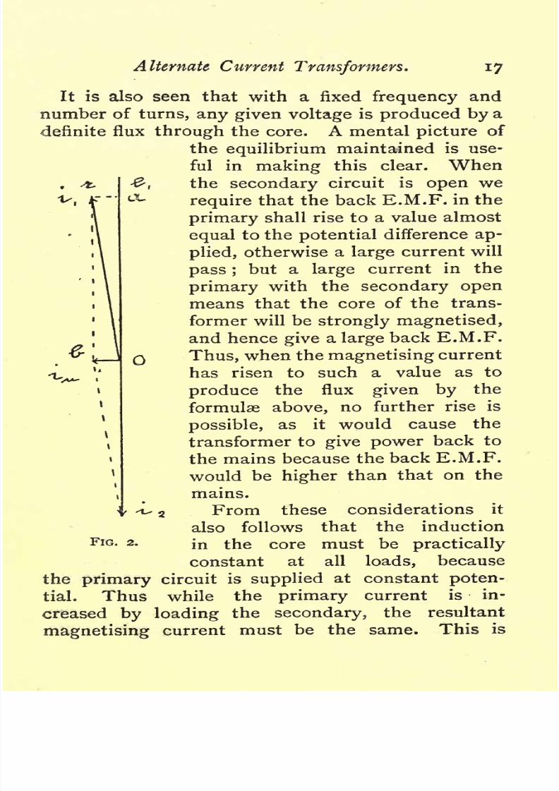
is also
seen
that
with
a fixed
frequency
and
number
of
turns,
any
given
voltage
is
produced
by
a
definite
flux
through
the
core.
A mental
picture
of
the
equilibrium
maintained
is use-
ful in
making
this
clear.
When
the
secondary
circuit
is
open
we
require
that
the back
E.M.F.
in the
primary
shall
rise to
a
value
almost
equal
to
the
potential
difference
ap-
plied,
otherwise
a
large
current
will
pass
;
but
a
large
current
in the
primary
with
the
secondary
open
means that the
core
of
the
trans-
former will
be
strongly
magnetised,
and hence
give
a
large
back
E.M.F.
Thus,
when
the
magnetising
current
has
risen to such
a
value
as
to
produce
the
flux
given
by
the
formulae
above,
no further
rise
is
possible,
as it would
cause
the
transformer
to
give
power
back
to
the
mains
because
the
back
E.M.F.
would
be
higher
than
that
on the
mains.
From
these
considerations
it
also follows
that
the induction
in the
core
must
be
practically
constant
at all
loads,
because
the
primary
circuit
is
supplied
at constant
poten-
tial.
Thus
while
the
primary
current
is
in-
creased
by
loading
the
secondary,
the
resultant
current
is
FIG. 2.

8/20/2019 ac transformer.pdf
http://slidepdf.com/reader/full/ac-transformerpdf 22/120
i8
The
Design
of
explained
by
the
fact
that the
primary
and
second-
ary
currents
practically
oppose
each
other
in
their
action on the core.
Fig.
2
shows
the condition
of
affairs
when
the
transformer
is loaded.
e
1
represents
in
magnitude
and
direction
the
primary
voltage applied
;
ii
is
the
primary
current,
which
lags
a
little
behind
FIG.
3.
i
2
is
the
secondary
current,
which
is
practically
opposed
in
phrase
to e
;
e
2
,
the
secondary
E.M.F.,
would
be
in
the
same
line
provided
the external
load is
non-inductive.
The resultant of
i
t
and
i
2
obtained
by
the
usual
construction
is
O
6,
which
represents
the current
actually
required
to
magnetise
the
iron.
This
is
here
called
i/m,
as
the
permeability
of
the
iron
its
*\
split
into

8/20/2019 ac transformer.pdf
http://slidepdf.com/reader/full/ac-transformerpdf 23/120
Alternate
Current
Transformers.
19-
two
components,
O
a,
Ob
by
projection
;
of
these
two,
O
a
represents
the
power given
to
the
primary,
and
when
multiplied
by
e
lt
gives
the actual
power
in
watts and
the O
6
represents
the
current called
i/u.
above.
Now
when the
secondary
circuit
is
open,
the
only
load
on the
primary
will
be that
due
to
the
hysteresis
and
the
Foucault
currents
in the
core.
$o
in
Fig.
3,
if
we
put
up
O
a
such
that
O
a
x
e
l
equals
the watts
wasted in
the
core,
and
then
make
O
6
the same
as-
in
Fig.
2,
we
get
the
resultant
of these
two
currents
in
O
c.
The scale
is
larger
than that
in the last
figure
for
sake
of clearness. Hence
O
c
represents
the
current
actually
taken
by
the
transformer when
the
secondary
is
open.
These
two
components
can
be
calculated
if
the
permeability
of the iron and
its
loss
by hysteresis
and
Foucault currents
at
different
inductions
have
been obtained.
The
total
watts
lost
as
obtained from
the
curves,
are
divided
by
e
l
to
get
*H
From the
value
of
JUL
for the iron as
the
induction
used
we
get
by
first
principles
that
io
1-25
x
ampere-turns
For
(A
=
TT
,
and
H
=
-
--
r^-
-
;
1
i
and
.
,

8/20/2019 ac transformer.pdf
http://slidepdf.com/reader/full/ac-transformerpdf 24/120
-2O
The
Design
of
where
/
=
the
mean
length
of
the
path
taken
by
the
induction
in
centimetres
;
li
=
the
maximum induction
in
C.G.S.
units;
IUL
=
the
permeability
of
the
iron
at that
induc-
tion;
Ti
=
the
number
of turns
on
the
primary
coil.
Having
thus obtained
ip,
we
can
get
i
the
no
load
current because
as
in
x
ip
thus
form
the
two
sides
of
a
right
angled triangle,
their
resultant
i
is
got
by
taking
the
square
root
of the sum
of their
square
or
O
C
2
=
C B
2
+
O
B
2
The
ratio of
the
current taken
by
the
transformer
at
no
load to the current
actually
required
for
the
hysteresis
has been
called the
power
factor
by
Dr.
Fleming,
and
this
gives
us
the factor
by
which
the
apparent
watts
have
to
be
multiplied
to
get
the
true
watts
wasted.
For
good
closed
circuit
trans-
formers
this factor
varies
from
*6o
up
to
nearly
*go
As
regards
the curves
of
iron
losses.
These
should
be
carefully
obtained
for each
sample
of iron
used
in
the
transformers.
It
is
possible
to
subdivide
the loss into
two
that
due
to
eddy
currents
in
the
iron
and
that
due
to
hysteresis
pure
and
simple.
Mr.
C.
P.
Steinmetz
has
worked
continuously
at
this
subject
for
some
years,
and
concludes
that the
hysteresis
losses
vary
as the
frequency
and
as the
i 6th
power
of
the
induction,
or
H
=
a
n
S
1
*
6
;
while
the
Foucault currents
vary
as
(n
|i)
2
,
or
(n
18)
2
,
a.
b
are
constants.

8/20/2019 ac transformer.pdf
http://slidepdf.com/reader/full/ac-transformerpdf 25/120
Alternate
Current
Transformers.
21
The
simplest
way
is
to
calculate
the
Foucault
current
loss, which
if
the
core
is
well
subdivided,
is
not
a
large
percentage
of
the
whole,
and then
to
get
the
hysteresis
loss
by
subtraction. For
instance,
using
the
generally
accepted
formulae,*
the
eddy
currents
in a
pound
of
iron
subjected
to
an
induction
of
4,000
at
a
frequency
of
100
complete
periods
per
second
works
out
to
'08
watt
if
the
plates
are
ten
mils
thick,
and
to
'18
watt
if
the
plates
are
15
mils
thick. The
watts
lost
per pound
in
hysteresis
will
vary
about the
region
of one watt
per
pound,
being
more
or
less
according
to
the
quality
of
the
iron.
So
that
with
the
thin
plates
the
eddy-current
loss
is
under
8
per
cent,
of
the
total.
It
is
also
convenient to
plot
the total
iron
loss
for
a
given
frequency
at
different
inductions,
and such
a
curve
will be added
for
reference.
The
other
theoretical considerations
to be remem-
bered
in
designing
a
transformer
are
of
a
more
general
nature,
such
as
keeping
the
copper
circuits
of as
small
a
perimeter
as
possible.
The
same
applies
to
the iron
circuits,
as
any
undue
length
in
the
iron
increases
both
the
iron
loss
and
the
idle
current
when the transformer
is
unloaded.
In
fact,
these
points
are so
easily
expressed
in
formulae
that
there
have
been
many
attempts
made
to
deduce
prac-
tical
conclusions
as to
the
best
design
from
these
alone.
The
results
thus
obtained have
not
been
*
For
thin iron
plates
the
watts
lost
per
cubic
centimetre
at
F,.
=
y
=
(
t
$
n
)
2
10
~
10
where
t
=
the
thickness
of the
plate
in
inches
B
=
the maximum
induction
n
=
the
frequency.

8/20/2019 ac transformer.pdf
http://slidepdf.com/reader/full/ac-transformerpdf 26/120
22
The
Design oj
satisfactory
as
a
whole,
and sometimes
have
led
to
mistakes
in
practice.
The
question
of the
cooling
surface to
be
allowed
is
one of
the
most vital
importance.
The
custom of
enclosing
transformers
in
cast-iron
cases tends
to
increase the
difficulty
of
preventing
the
temperature
becoming
too
high.
The heat
generated
in
the
transformer
has
to
pass
first
from
it
into
the
sur-
rounding
air
inside
the
case,
then from this
layer
of
air
into
the
case,
and
finally
from
the case
into
the
surrounding
medium. This
triple
transference
is
greatly
assisted
if
oil
is
used
to
fill
in
the case.
The
oil
acts
by
conduction
and
convection
in
carrying
the heat
to
the
case,
and
thus
materially
reduces
the
final
temperature
of the transformer. The
oil
is
primarily
said
to be
used
for
insulation
pur-
poses,
but its
action as
a
cooling
agent
is at low
voltages
the more
valuable
of
its
properties.
The
actual
design
of
the sections
of the
two
copper
circuits
for
a given
loss
is
a
problem
similar to
those
occurring
in
dynamo
calculation,
and
presents
no
new
difficulties.
The
following
formulae,
which
are
simply
deduc-
tions
from
the
specific
resistance
of
copper
will be
found
very
useful
in
determining
the
sizes of
the
copper
circuits
:
If s
=
the
section
of
the wire
in
square
inches;
d
=
the
diameter
of the wire
in
inches
;
z
=
the
maximum
current
in
amperes,
as
read
on
a
Siemens
dynamometer
;
r
=
the
number
of
turns
in
the
circuit
;
7r
=
the
mean
length
of
a
turn
in
feet
;

8/20/2019 ac transformer.pdf
http://slidepdf.com/reader/full/ac-transformerpdf 27/120
Alternate
Current
Transformers.
23
/
=
the total
length
of
conductor
in
feet
;
#=the
drop
of
volts
allowed
at
maximum
current
;
y
=
the
resistance in
ohms;
g
=
the
weight
of
copper
in
pounds.
Then for
rectangular
sections
_
T
T
9*2
I0~
6
(3)
g
=
S
T
7T
X
3-85
T
TT
can in
each
case be
replaced
in the
above
by
I,
but
it
is
well
to
record the
mean
diameter
in
each
design.
With
wire
of circular
section
these formulae
become
d=
ii'75
d
2
3*02
(4)
The
constants
9*2
and
11*75
give
the
respective
sizes and resistances at
a
temperature
of
about
I05deg.
F.,
which
may
be considered as
a fair
allowance
for
heating,
and
on
assumption
that
the
copper
is of 100
per
cent,
conductivity.
If
a
higher
temperature
is
allowed,
or
inferior
copper
is
used,
these
constants
must
be
modified
accordingly.
There
is,
however,
one
other
important
point
to
be
considered,
and
that
is the
question
of
magnetic

8/20/2019 ac transformer.pdf
http://slidepdf.com/reader/full/ac-transformerpdf 28/120
24
The
Design
oj
leakage.
When
most
transformers
are
tested,
it
will
be
found
that
the
drop
in
volts
in
the
secondary
between
no load
and full
load
is
more than
can
be
for the resistances
of
the cir-

8/20/2019 ac transformer.pdf
http://slidepdf.com/reader/full/ac-transformerpdf 29/120
Alternate
Current
Transformers.
25
cuits.
This
is due
to the fact that
at
full load the
whole
field
produced
by
the
primary
does
not
pass
through
the
secondary,
but
some
portion
of it is
forced
out
by
the
action of the
secondary
current,
and
consequently
we
get
a
drop
in
volts.
This
is
an
important
point,
but it will be
more
readily
under-
stood
after
the trial
designs
have
been
given.
It will be
best to
assume
a
given
quality
of
iron
taken
from
practical
test,
and hence
the
two curves
given
have been
prepared. Fig.
4 gives
the
watts
lost
per
pound
of
iron at
100
frequency
with
varying
induction.
For
slight
alterations
of
fre-
quency
it
will
not
cause a
serious
error
to assume
that
the
loss
varies
directly
as the number
of com-
plete
periods
per
second,
as the
plates
for which the
curve is
drawn were
10
mils thick.
The iron is
not
the
best
that
can be
obtained,
but
still
is
a
fairly
good
sample.
The
other
curve,
Fig.
5,
giving
the
permeability,
/*,
for
the
various
inductions,
was
also
calculated
from
actual results
with
the same
iron,
and
will be
used
when
working
out the
open-circuit
currents. It
will
be
noticed
that the
curve
gradually
rises
till the induction
reaches
7,000,
and
after
that
it
is
nearly
flat.
If
carried
farther
the curve falls
again,
but it is not usual
to
work
at
higher
inductions.
With
superior
qualities
of
iron
the
jj.
curve
is
raised
throughout
its
entire
length,
but the most noticeable
feature
of
the
change
is
that
the
permeability
at low
induction is
very
much
increased.
The
following
is
a
useful
routine to
adopt
in
making
designs
:
First
fix
the
iron
and
copper
losses

8/20/2019 ac transformer.pdf
http://slidepdf.com/reader/full/ac-transformerpdf 30/120
The
Design
of
be
done.
Then
fix
roughly
the
dimensions
of
the
iron
circuit
and
calculate
the
weight
of
iron.
From
\
the
iron
loss obtain
the
loss
per
pound,
and
hence,
induction.
the

8/20/2019 ac transformer.pdf
http://slidepdf.com/reader/full/ac-transformerpdf 31/120
Alternate Current
Transformers.
27
^cross-section
of
the
iron,
gives
the
total
flux,
and
from
formula
(i)
the number
of
turns
required
in
each
winding
can
then
be
found.
Obtaining
the
mean
length
of
turn
approximately,
the
sections
or
diameters
of
the
wires
can
be
found,
together
with
the
weights
for the
assumed
copper
loss,
from
formulae
(3)
and
(4).
The
question
then
becomes
one
of
mechanical
design
to
get
the
winding arranged
symmetrically
with
ample
insulation.
It
will
usually
be
found
necessary
to
alter
slightly
the
iron
circuit,
and
very
often
the other
details
may require
modifi-
cation.
The
main elements
in
the
design
being
fixed,
the
calculations
of
iron
loss
and
magnetising
current can
be
carefully gone
through,
and
finally
the
whole
data should
be
collected
into
a
concise
form
for
comparison
with other
designs.
The
watts
lost
per square
inch
cooling
surface at
no
load
and
full load should be
recorded,
although
the
different
types
are
not
directly
comparable
in
this
respect.
The
results
thus
obtained
are
sure
to
suggest
various
alterations
likely
to effect
improvements.
The most
economical
plan,
however,
is
to
make
many
designs
for
two
outputs varying considerably
so
as
to
obtain the most economical
forms for
these,
and
then
to
get
out
the intermediate
sizes
by
aid
of
interpolation.
In
this
way
the
merits
of
any given
type
form
a
separate
investigation,
and
the
error
of
comparing
a
badly-proportioned
transformer of
one
type
with a
well-designed
transformer of
another
type
may
be
avoided.
I
to
designs
for
a
six-kilowatt

8/20/2019 ac transformer.pdf
http://slidepdf.com/reader/full/ac-transformerpdf 32/120
28
The
Design
of
above
method
of
working.
The
reader
can
then
for
him-
self
try
the effects of
small
alterations
in
the different
circuits
on
the
efficiency
and
cost.
The
following
may
3
i
FIG.
6.
be taken
as a fair
efficiency
to be
aimed at as
a first
attempt
:
Iron
loss,
150
watts
=
2,\
per
cent,
of
the

8/20/2019 ac transformer.pdf
http://slidepdf.com/reader/full/ac-transformerpdf 33/120
Alternate
Current
Transformers.
29
at full
load,
or
a
total
copper
loss of
2
per
cent.
Transforming
ratio,
2,000
volts
to
100
at
full
load.
Thus it
will
be
well
to
make
the ratio
2,000
to
102 at
no
load
to
reduce
the
effect
of
the
copper
drop
and
mag-
:
netic
leakage.
The
frequency
we
will
assume
to
be
100
complete
cycles per
second.
The
designs
will
be taken
at
random,
and
will
not
necessarily
be the
most
eco-
nomical
of
the
various
types.
The
cost
of material
may
be
taken as
giving
some
indication
of
the
probable
cost
of
manufacture.
So,
assuming
the
copper
to cost
lOcLper
pound,
and
the
iron
4d.,
we
shall
work
out in
each case the cost
and
weight
per
kilowatt
output.
First
Design.
This
shall
be
of
the
long
shell
type
having
a
square
core.
This form of transformer
is
largely
used both
on the Continent and
in
England,
but
the
different
makers
use
various
methods
of
building
up
the core and
of
winding
the
copper
circuits.
We
will assume that a
4in.
core
is
required,
and
that
the
general
outline
of
the
iron circuit
is
that
shown
in
Fig.
6.
The
gross
area of the section
of
the
core
is
then
15*4
square
inches,
and
allowing
for
85
per
cent,
of the
space being
taken
up
by
the
iron,
this
gives
a
core
area
of
13*1
square
inches,
or
84*5
square
centimetres.
Adding
up
the
lengths
ofthe
various
parts
we
get
a
total
length
of
48in.,
which
gives
a
volume of
630
cubic
inches
of
iron,
weighing
I761bs.
Now
the
total
iron
loss
was
to
be
150
watts,
so
that
the
loss
in
hysteresis
and
Foucault
currents
for
lib
of iron is
=
'85
watt.
From
the
curve,
Fig.
4,
it
will
be seen
that this
corresponds
to
an

8/20/2019 ac transformer.pdf
http://slidepdf.com/reader/full/ac-transformerpdf 34/120
3O
The
Design of
induction
of
about
3,600
lines
per
square
centi-
metre.
Hence
the
total flux F
=
3,600
x
84*5.
=
304,000.
From
this
we can
now
by
aid of
(i)
determine
the
number
of
turns
required
in
both
windings.
For
the
secondary
we
have
2
=
4*45
F
r
2
n
lo
8
;
and
in
this
case
2
=
102,
F
=
304,000,
n
=
100
;
102
.*.
r
2
=
x
io
8
=
75*5.
4*45
x
100
x
304,000
An
even
number
of turns
must
be
used
for
con-
venience,
and
hence
76
will be
nearest to
the
number
required.
It
is
always
well
to calculate
the
secondary
first,
and to obtain
an
even number
of
turns
in
it,
as it is not
well
to
introduce
half
and
quarter
turns
in
either of
the
windings.
We
get
the-
number
of
turns
on
the
primary
from
the
ratio
ot
the
voltages.
Thus
r
2
e
2
102
76
x
2,000
.-.Ti-
---
1,490.
The next
step
to
be
considered
is
the
arrangement
of
the
copper
circuit.
It
is
found
that
if the
coils-
are
wound
separately
and
placed
one
at
either
end
of
the
core,
as
shown
in
Fig.
i,
a
large magnetic
leakage
takes
place
at
full
load.
This
causes
a
drop^
in
the
voltage,
which
is
very
objectionable,
as
explained
above.
There
are several methods
of
obviating
this
defect,
and
one
is to
split
the two-

8/20/2019 ac transformer.pdf
http://slidepdf.com/reader/full/ac-transformerpdf 35/120
Alternate
Current
Transformers.
**
fe*
Z-J-
FIG. 8.

8/20/2019 ac transformer.pdf
http://slidepdf.com/reader/full/ac-transformerpdf 36/120
32
The
Design
of
windings
into
sections,
which
are
placed
alternately
along
the
core,
Fig.
8.
In
this
way
the
demag-
netising
effect
of
the
secondary
is
not
concentrated
at
one
part
of
the
core,
and
by
the subdivision
the
magnetic
leakage
is
reduced
to
reasonable
limits.
So
in
this
transformer
we will
make
four
segments
in
the
secondary,
and
interleave
them with
four
of
FIG.
7.
primary
wire.
The
necessary
radial
insulation
will
be
about
that
shown
in
Fig. 7,
and
the
depth
of
winding
we
may
assume
to
be
ifin.
The
mean
circumference
of
the
winding
will
then be
i*97ft.
=
TT.
Designing
the
primary
first
and
using
round
wire
for
it,
we
get
from
(4)

8/20/2019 ac transformer.pdf
http://slidepdf.com/reader/full/ac-transformerpdf 37/120
Alternate
Current
Transformers.
33
Here i
=
3 amperes
;
TJ=
1,490
turns;
TT
=
i
'97ft.
=
20
volts
=
i
per
cent.
;
I
=
2,94oft.
;
=
/
V
x
1,570
x
i'97
x
75
20
Thus,
wire
72
mils
diameter
will
give
the
i
per
cent, loss
at
full
load.
The
insulation
and
clearance
required
in
winding
would
bring
the
pitch
of the
wire
up
to
about
90
mils.
Dividing
the
depth
of
winding
by
this,
we
get
-^-
=
19*4
as the
number of
layers
which
could
be
got
in.
In
each
segment
of
winding
it
is well
to have
a
sub-division,
so
that each
half
can
be
wound
separately
from the
bottom.
This
gives greater
insulation,
and
less
difference
of
potential
between
adjacent
wires,
than
winding
all in
one
division.
So
there
should
be turns to
each
segment
of
primary
wire
=372*5,
and
half
this
number
in
each
compartment.
As it is
well to work to even
numbers
where
possible,
we
could
wind
five
compartments
with
19
layers
of
10
turns and three
compartments
with
18
layers
of
10
turns
which
would
give
the
total
number
required.
The
actual
length
of
core
taken
up by
the
primary
wire
will
be 8
x
10
x
*090
=
7*2in.
As the mean
length
of
turn
may
be
altered
in
the
final
adjustments,
the
other
details
as
to
weight
of
copper,
resistance
etc.,
will
be left
till the
actual dimensions
are
fixed.

8/20/2019 ac transformer.pdf
http://slidepdf.com/reader/full/ac-transformerpdf 38/120
34
The
Design
of
Proceeding
with the
secondary
copper,
which
on<
account
of
its
large
size
should
be
of
rectangular
section
we use the
formulae
in
group
3.
The
section,
S,
in
square
inches
.
t
In
this
case
i.
2
=
60
amperes
;
r
2
=
76;
6=1,
and
?r
=
1*97
as
before
;
so
that /
=
i5oft.
60x76
x
1-97x9-2
.
'
.
S
-
--
-
x
io~
6
=
-083
sq.
in.
The number
of
turns
76
cannot
be
divided
exactly by
8
the
number of
compartments
so that
we
must
have
a
different
number
of
turns
in
some
of
them.
Thus,
if
we
wind each
segment
with
19
turns
one
compartment
having
10
turns
and
one
nine
we
shall
get
the
total
number
correctly.
In
this
case
it
will
be
best
to use
tape
and
to
allow
for
10
layers.
Thus,
-give
the
thickness
of the
tape
and
the insulation
=
'175^1.
Allowing
35
mils
for
insulation,
this leaves
'140
in.
for
depth
of
copper
and
tape
;
('I4oin.
x
-6ooin.)
will
give
the
section
required.
This insulated
tape
will
thus
measure
('i75in.
x
-635m.),
and the
length
of core
taken
up
by
the
secondary
will be
8
x
-635
=
5'iin.
Insulating
flanges
are
required
between
the
seg-
ments
and
also
between the
two
compartments
of
each
segment.
The
space
taken
up
by
these,
with
the
necessary
winding
clearance,
will
be
about
2in..

8/20/2019 ac transformer.pdf
http://slidepdf.com/reader/full/ac-transformerpdf 39/120
Alternate
Current
Transformers.
35
The
end
flanges
will be
thicker,
and
clearance
will
be
required
between
them
and
the
yoke
which
will
account
for
another inch.
Thus
we
get
for
the
length
of
core
;
Primary
wire
...........................
7-2
Secondary
wire
........................
5*1
Flanges
and
clearances ............
3*0
Say, I5*5in.
in
between
yokes.
This
only
makes
the
transformer half
an
inch
shorter
than
the
rough
sketch,
Fig.
6.
From
Fig. 7
we see that
the
space
allowed
between
core
and
yokes
is
just
that
required,
so
that
the
length
is the
only
dimension
needing
alteration.
The
copper
circuit
calculations
will
therefore
be
correct,
and will
not
need
alteration,
a&
might
have
been the
case,
if for
instance,
the
depth
of
winding
had
to be increased
owing
to
the
wire
taking
up
too
great
a
length
on
the core.
We
will
therefore
proceed
to
carefully
calculate
the
iron
losses
and
magnetising
current.
Assuming,
as
before,
that the
total section
of
the two
yokes
together
is
equal
to
that
of
the
core,
the
volume
of
iron
=
13*1
x
47in
=
616
cubic
inches,
or
i72'5lb.
For T
2
=76,
the
exact
F
from
(i)
is
302,000
C.G.S.
lines,
therefore
g=
3
Q2
>
000
=3,580.
y
4'5
From
curve
4
this
corresponds
to
a loss of
84
watt
per
pound,
so
that
the
total
iron loss is
172*5
x
-84
=
144*8
watts. From this
we
get
that
the
current

8/20/2019 ac transformer.pdf
http://slidepdf.com/reader/full/ac-transformerpdf 40/120
36
The
Design
oj
required
by
the
iron
losses at
open
circuit
=
=
0724
ampere
=
i
H
Fig.
3.
The
next
step
is
to
calculate
ijm,
the
current
re-
quired
by
the
permeability
of
the iron.
This
is
got
by
means of
the formula
(2)
:
For
this
transformer,
/,
the
mean
length
of
the
magnetic path
in
centimetres,
is
123
;
/x
at
this
induction,
from
Fig.
5
=
1,960
;
Tj
=
1,490;
3,580
X
123
o
o
/.
lu.
=
c
J
-
-
-
-p
=
'0858 ampere.
1,960
x
1,490
x
176
As
from
Fig.
3,
i
H
and
ijm
are the
two
sides of
a
right-angle
triangle,
we
obtain
the
magnetising
or
no-load
current
by
taking
the
square
root
of
the
sum
of
the
squares
of these
two.
Thus
:
i
=
\/*
H
2
+
*>
2
:
=
\Ao724
2
+
-08582;
=
'H2
ampere;
which is
374
per
cent,
of
the
full-load
current
in
the
primary.
Now
completing
the
details
for the
primary
copper
by
aid
of
(4),
we
get
the
resistance
from
7
L
T
Ll
i75
d
2
=
1-97
x
1,490
x
1175
072
x
-072
=
6*69,
say 67
ohms.

8/20/2019 ac transformer.pdf
http://slidepdf.com/reader/full/ac-transformerpdf 41/120
Alternate
Current
Transformers.
37
It
will
be seen
that when
the full
primary
current
ofthree
amperes
is
flowing,
this
gives
a
loss
of
20
volts
as
intended.
The
weight
is
now
obtained
from
g
=
d
2
7TT
3
02;
placing
the
respective
values of
d,
TT
and
T
X
we
get
g
=
4
61b.
The
secondary
is
next
treated
in
the
same
way
by
aid
of
(3),
which
applies
for
strip
or
any
wire
when
the
section
is known.
Hence,
r
=
^
lo-*;
or,
placing
in
the value
as determined
above,
76
X
I'q6
XQ'2
r
=
/_
_2_
083
=
'0166
ohm.
This when
multiplied
by
60
amperes,
the
maximum
current,
gives
us a
drop
of
one
volt.
These calculations
of
the
resistances
of
the
primary
and
secondary
winding
check
the
accuracy
of the
previous
work,.
in
which
a
i%
drop
was
assumed.
The
weight,
g,
equals
S
r
2
TT
x
3-85,
and
so
g
=
'083
x
76
x
1-96
x
3*85,
=
47'5lb.
Now
collecting
the
details
of
the
design
together,
we
get
the
following
list
:
Six-Kilowatt
Transformer,
Shell
Type:
Ratio
of
transformation,
2,000/100
volts;
^^
=
100.
Core,
4in.
square
;
area
of
iron,
84/5
square
centi-
metres.

8/20/2019 ac transformer.pdf
http://slidepdf.com/reader/full/ac-transformerpdf 42/120
38
The
Design
of
,
F
=
302,000,
I
=
123.
Primary
:
T
X
=
1,490.
TT
=
1*96.
Conductor,
72-mil
wire
wound
in four
segments
of
two
divisions
as
follows.
5
divisions
of
19
layers
of
10
turns.
3
l8
*o
turns.
Maximum
depth
of
winding,
i'7in.
r
=
6*7
ohms
;
loss
=
i
per
cent.
;
weight,
461b.
Secondary
:
r
2
=
76.
TT
=
1*96.
Conductor,
strip
('I4oin.
x
-6ooin.),
wound
in
four
segments
of two
divisions,
as
follows
:
4
divisions
of
10
layers
of
i
turn,
and
4
9
J
turn-
Maximum
depth
of
winding,
i*75in.
r
=
*oi66
ohm
;
loss
=
i
per
cent.
;
weight,
47'5lb.
Losses
Iron
.........
I
44'8
watts,
or
2*42
per
cent.
Copper,
primary
60
i
Copper,
secondary
60
i
264-8
watts.
Therefore
the
efficiency
at
full
load
=
6,264-8
=
95-6
per
cent.
The watts wasted
in
the
iron at no
load are
144*8,
and
the
apparent
watts at
no
load
=
2,000
volts
x
112
ampere
=
224
watts.
So
the
power
factor
in
this case
=
44
=
'648.
The
weight
of
iron
=
172*5^.,
at
4d.
per
Ib.
=
57*55.
copper
=
93*5lb.,
at zod.
per
Ib.
=
78'os.
Total
2661b.
i35'5s

8/20/2019 ac transformer.pdf
http://slidepdf.com/reader/full/ac-transformerpdf 43/120
'jy
Alternate Current
Transformers.
Dividing
by
the
output,
we
find
that
the
results
have been
obtained
by
using
44*3^.
of
copper
and
iron
per
kilowatt,
and
at
a
cost
of 22*6s.
for
the
materials
;
also that
the
ratio of
weight
of
copper
to
weight
of
iron
=
-55.
The
other
point
to
be
considered in the
trans-
former
just
designed
is the
cooling
surface
per
watt
wasted
at
no
load
and
also
at full
load.
This
should
give
an
approximate
idea
of
the
temperature
which the
transformer
will
attain
when left
on
the
circuit.
The
investigation
is,
however,
by
no means
so
simple
as
might
be
expected
at first
sight.
Suppose,
for
instance,
we
calculate
the
total
cooling
surface.
The surface
of the
copper
coils
and
insulation
may
be
taken
as
that
of
a
cylinder 9
Jin.
dia-
meter
and
isin.long,
and
thus
=
TT
x
gjin.
x
I5in.=
438
square
inches.
The
end
flanges
may
help
to
cool
the
coils,
and
hence,
the
surface
of
these should
be
added
=
36
square
inches.
The iron in
the
yokes
will
add
considerably
to the
above,
the
exposed
surface
of
the
iron is about
780
square
inches,
so
that
the
total
cooling
surface will
be
1,254
square
inches.
The
watts
wasted
at
no
load
are
144*8,
and
at full load
the total
loss
rises to
264*8
watts.
Working
with
these
figures
and the
cooling
surface
given
above,
the
loss comes
out at
115
watt
per
square
inch
at no
load,
and
211
at full
load.
These
figures
appear
ample,
if
viewed
in the
light
of
dynamo
magnet
practice,
but
it
must
be
remem-
bered
that
dynamos
have
moving parts
which
create
currents
of
air
round
the
field
magnets,
tending
to

8/20/2019 ac transformer.pdf
http://slidepdf.com/reader/full/ac-transformerpdf 44/120
40
The
Design
of
make
the
cooling
surface
more
effective,
whereas
the
transformer
not
only
is
motionless,
but
is
boxed
up
in
an
iron
case
which
prevents
a
free
circulation
of
air. Thus
the
heat
has
to
be transferred
from
the
transformer
to
the air
in
the
case,
again
from this
air
to
the
case,
and
finally
from
the case to
the
air
outside.
This is
not
absolutely
correct,
as the
transformer
loses
heat
by
conduction
where
the
yokes
rest on the
iron
box,
but
still,
roughly,
we
may
expect
at least
two
and a
half times
the
rise of
temperature
that
would
be
found
on
a field
magnet
having
the
same
loss
per
square
inch
cooling
surface.
Much
of
course,
depends
on
the
shape
and
mechanical
construction
of
the
transformer,
and
in-
dividual
constants
should
be
obtained
from
practice
for the
heating
formula
for each
type.
Now,
in the above
calculation,
we
have
worked
with
the total
cooling
surface
and
the total
loss.
Even
if the
loss were
uniform
through
the
mass this
would
give
widely
different
internal
temperatures
according
to
the
depth
of
material.
It
is,
however,
this
internal
temperature
that
causes
faults
in transformers
by
heating
the insulation
on
the wires
up
to a
point
at
which
it either chars or
becomes
rotten.
In
the
trans-
former
designed
above the most
dangerous
point
would
be
the
bottom
of
the
coil
wound
in
the
centre
of
the
transformer. The heat
generated
in
the
iron
immediately
under
this
would
pass,
to
a
considerable
extent,
up
through
the
copper,
and
this
heat
has
to
be
dissipated
by
the
surface of
the
copper
as well
as
the
copper
watts.
Considering
a
vertical
section
lin.
long, iron
loss in
part
of
core

8/20/2019 ac transformer.pdf
http://slidepdf.com/reader/full/ac-transformerpdf 45/120
Alternate
Current
Transformers.
41
cut
off
would
be
3*1
watts,
and
the
copper
loss
in
the
wire
would
be
about
seven
watts,
giving a
total loss
in
the section
of
10*1
watts.
Now,
the external
cooling
surface
is
only
TT
x
g^in.
=
29 square
inches,
so that
the watts
per
square
inch
cooling
surface
in
this
central
section rises
to
0*35
at full
load,
whereas
the
mean obtained above
was
only
o'2ii.
This is
under
the
assumption
that
the
whole
of
the
heat
generated
in
the section is transmitted
radially
to
the
surface,
which is not
absolutely
correct
;
but
if
the coil
is
in
the
middle
of
the
winding
it
is not
likely
to
give
off
much heat
to
the
adjacent
coils
which
will
be
at
much
the
same
temperature.
In
comparing
the
figures
relating to
the cooling
of
transformers the
hottest
point
of the
copper
circuits
should
always
be
considered,
and
not
the
mean
external
temperature
only.
The
highest
temperature
in
the
iron
does
not
affect us
much,
as
no
ill
effects
occur from
this cause
unless the hottest
part of
the
iron
is
close
to
the copper,
which
is
seldom
the
case.
The
yokes
in
this
design
have
the
largest
amount
of surface
per
watt
wasted,
and
hence
keep
cooler than the
centre core. Some
makers
have
reduced the section of the
yokes
for this
reason,
as
weight
can
be
saved
by
so
doing
and
the
temperature
still
kept
normal.
This,
of
course,
causes
a
higher
induction
in
the
yoke,
and as
the
curve
of iron
loss
rises
rapidly
with
the
induction,
the
watts
per
pound
will increase
more
rapidly
than
the
weight
diminishes.
Hence
the
total
iron
loss is
increased
by making
the
yokes
of
smaller
section.
Again,
in the
inverse
direction,
some
makers
have

8/20/2019 ac transformer.pdf
http://slidepdf.com/reader/full/ac-transformerpdf 46/120
42
The
Design
of
put
more
section
of
iron
in their
yokes
than
in
the
core.
This
certainly
lowers
the
iron
loss
slightly,
but,
as will
be
found
by
actual
trial,
the effect is
not
rudL
FIG.
9.
very
marked,
and,
perhaps,
is
hardly
worth
the
increase
in
labour
and
material
charges.
of
constructing
the iron
cores
for

8/20/2019 ac transformer.pdf
http://slidepdf.com/reader/full/ac-transformerpdf 47/120
Alternate Current
Transformers.
43
transformers of
proportions
similar
to
those used
in
the
above
designs
are
very
numerous.
Almost
every
maker has
a
different
way,
and
the ad-
vantages
and
disadvantages
of the
various methods
are
mainly
those
of cost
and
convenience
of
manu-
facture.
In
England
the
plates
are
usually
ar-
ranged
so
as to
interleave
one
with
the
other,
so
that
each
successive
plate
added,
covers
up
the
joint
in
the
preceding
layer.
There are a
large
number
of
different
ways
of
doing
this
with
the
present
type,
Fig. 9,
shows one
method and
the
reader will
have
no
difficulty
in
devising
many
others.
In
this
way
the
magnetic
resistance
is
practically
reduced
to
that
offered
by
the
iron,
and
the
air
resistance
is
negligible.*
So
in
the
curve of
permeability,
Fig.
5,
the
necessary
data
were obtained
from a
transformer
having
its
core
built
up
on the
system,
and the effect of
small
air
resistance
is
thrown
into
the
magnetic
resistance of
the
iron.
In
some
cases,
however,
the
different
parts
of
the
iron
circuits
are
fitted
together
at
faced
joints,
and
then
the
air
resistance of
those
joints
will make
a considerable addition to the
current marked
*>,
Fig.
3.
The
same
formula
as
used for
determining
the
ip,
required
by
the
iron
(2)
can
be
used for
finding
out the increase of
current
due
to
the
air-gap,
which
may
be
called
*
This
will
be
readily
seen when
looking
at
the
case
worked
out
below
for
an
air-gap having
an induction
of
3,000
in it.
By
the
interleaving
method
this
induction
can
easily
be
reduced to
one
line
per square
c.m.,
which
would
reduce the
current
required
for
the
gap
to
a
figure
negligi-
ble as
compared
with
that
required
by
the
iron,
i.e.,
'000,191
ampere
as
compared
with
'0,858
ampere
for
the
iron.
In
addition to this
the
total
gap
is
much
less
in
the
interleaved
type
and
will
a?ain
reduce
the
effect.
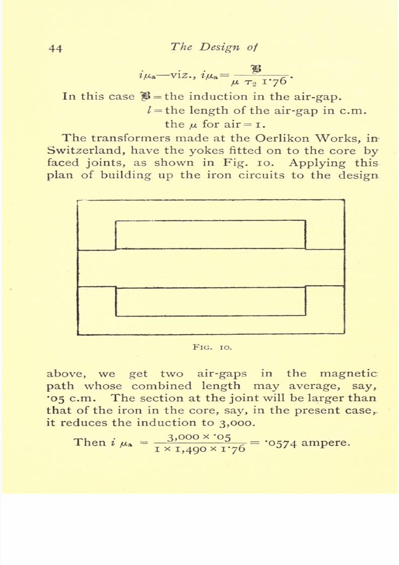
8/20/2019 ac transformer.pdf
http://slidepdf.com/reader/full/ac-transformerpdf 48/120

8/20/2019 ac transformer.pdf
http://slidepdf.com/reader/full/ac-transformerpdf 49/120
Alternate Current
Transformers.
45
The
yu
current
due
to
the iron
alone
as obtained
above
=
0858
ampere.
The
total
iju,
therefore
=
'1432
Working
out
the
total
no-load current
as
^before,
i=
7-07242
+
-I432
2
,
=
*i6i
ampere,
or
5*37
per
cent.
:So we see that the effect
of
the
joints
is to
raise
the
FIG.
ii.
no-load
current
from
3*74
to
5*37 per
cent,
of
the
total full-load
current.
The
average
length
of
air-
gap
as
taken above
may
be rather
excessive,
but
it
is
extremely
difficult
to
get
good
plane
surfaces
on
the
cores and
yokes
which
are built
up
of
thin
laminations.
Hence,
although
the
faced
joints
reduce
the
labour
charges
on
the
transformer,
they
have
almost
been
abandoned
in
England
on
account of
the
increase caused
by
them
in
the
no-load
current.

8/20/2019 ac transformer.pdf
http://slidepdf.com/reader/full/ac-transformerpdf 50/120
46
The
Design
of
Fig.
ii
shows this
type
of
transformer
as
made
by
Messrs.
Brown
and
Boveri,
of
Baden.
As
will
be
seen
the
two
yokes
are
in
this
case
merged
into
one,
and
the
system
of
winding
is
different
to
that
worked
out in
the
design
above.
The
primary
and
secondary
wires are
wound on
insulating
cylinders
separately,
and
slipped
on
individually
over
the
core.
This
method
is
also
effective
in
preventing
the
magnetic
leakage,
and it
enables the
labour
on
the
transformer
to be
sub-divided.
This
sketch
simply
shows
the Brown
type
of mechanical detail
applied
to the calculations made
above,
and
does
not
give
the
relative
proportions
adopted
by
Mr.
Brown.
The
clamping
arrangements
are
left
out
for the sake of
clearness.
The
next
steps
to
be
taken
in
order to obtain
the
best
design
of
this
type
are
as follows
:
(a)
Design
transformers with
slightly
smaller
and
larger
cores
and
compare
the
figures
obtained
with
those
above;
(6)
next
try
the
effect
on
the
best
design
of
shortening
the
core
and
winding
with
a
greater
depth
of
copper
;
if
this
step improves
the
design
without
materially
decreasing
the
cooling
effect,
it should
be carried
further.
The
practice
thus obtained
in
quickly
running
out the
leading
details
of
the
various
parts
will
soon
enable
the designer
to
gain a general
idea
of
likely
methods
of
improvement,
and
also
give
him
an
insight
into
the
capabilities
of
the
type.
These
calculations
would,
however,
take too much
space,
so
we
will
proceed
to
design
another
type
of
transformer
in
which
the
relative
shapes
of the
copper
and
iron
circuits
are
the exact
opposites
to

8/20/2019 ac transformer.pdf
http://slidepdf.com/reader/full/ac-transformerpdf 51/120
CHAPTER
II.
Second
Design.
The
transformer
just
designed
had
a
comparatively
long
iron
circuit
of
small
section,
with the
copper
wound
round
it.
Hence the
I for
the
iron
was
large,
and
the
mean
perimeter
for
the
copper
circuit
small.
<i4i
FIG.
12.
The
next
design
shall
be of the
type
associated
with
Mr.
W.
M.
Mordey,
in
which
the
path
of
the
magnetic
lines
is
short,
but
the
copper
circuit
has a
comparatively
large
perimeter.
We
will
assume,
as
before,
a definite
size
of
core,
Fig.
12,
and then afterwards
alter the
shape
if
neces-
sary.
The relative
of
the
core
plates

8/20/2019 ac transformer.pdf
http://slidepdf.com/reader/full/ac-transformerpdf 52/120
The
Design of
and
yokes
are
deter-
mined
by
mechanical con-
siderations. The
stampings
consist of
hollow
rectangles
of
such
dimensions that
the
pieces
removed from
the centre
will
bridge
the
two
long
sides,
and thus
form the
centre
core,
Figs,
12,
and
13.
It
will be seen
that
with this
method
of
building up
the
iron
cir-
cuit
there will be
space
wasted
between
the
adja-
cent
plates,
except
just
at
the
end
of
the
core,
and
only
half the
quantity
of
iron
can
be
got
in
that
would
be if the
plates
were
arranged
to
break
joint
as
in
Fig, 9.
Hence
the
Mor-
dey
transformer,
although
made
in
the
smaller
sizes
of the
general proportions
shown,
is now built
up
on
a
different
principle.
Making
the transformer
3ft.
long,
and
allowing
for
85 per
cent, of the
space
being
taken
up by
the
plates,
we
get
for the volume
of

8/20/2019 ac transformer.pdf
http://slidepdf.com/reader/full/ac-transformerpdf 53/120
Alternate
Current
Transformers.
49
|
(7
x
ioj)
-
(3i)
2
}
36
x
-85
=
i,
880
cubic
inches,
which
will
weigh
5261b.
The loss we
assumed
in the iron
is
150
watts,
which
gives
-=
'285
watt
per
pound;
From the
curve,
Fig,
4
this
corresponds
to
a
flux
of
1,700
lines
per
square
centimetres.
Now the
area
of the
centre
core
of
this
transformer
is
3^-in.
x
36in.
x
-85
=
107
square
inches
=
690
square
centimetres,
so that
the
total
flux will
be
1,700
x
690
=
1,172,000
C.G.S.
lines.
We
can
now
proceed
to
design
the
secondary
winding.
Using
formula
(i)
2
=
4*45
F
r
2
n io~
8
,
we
get
102
=
4*45
x
1,172,000
x
r.y
x
100
x
io~~
8
.
_
102
~4'45
X
1*172
=
19-6.
We
must
have an
exact
number
of
turns,
as with
this
make
of
transformer
the
wire can
only
be
got
at
at the
ends of
the
core,
and
may
assume
20
turns
as
the
nearest
number to
the
above.
In
this
design
there
is
as
much
likelihood of
getting
magnetic
leakage
as
in
the
last,
but
for the
present
it
will
be
sufficient
to
calculate
the
winding
for
two
coils
only,
wound
side
by
side
i.e.,
one
primary
and
one
second-
ary
;
and then
finally
we
must
leave
sufficient clear-
ance
to
allow
for further
sub-division if
necessary.
The mean
perimeter
of both
windings
will
therefore
8/20/2019 ac transformer.pdf
http://slidepdf.com/reader/full/ac-transformerpdf 54/120
5
The
Design
of
be the
same,
and
will
be
about
j'tft.
The
number
of turns
of
the
primary
is
obtained
from
the
ratio
of
voltage
^=^-
T
2
e.
2
2,OOO
X
2O
'
The
primary
wire
required
to
give
the
i
per
cent.
drop
at
full
load
we
get
as
before
from
(2)
,
and
here
h
=
3
TT
=
7-5
Tl
=39
2
#
=
20
...
d=
/3X3Q2
X
7-5XII75
IO
-H
V
2O
=
0721.
Say
72-mil
wire,
covered with
insulation to
a
diameter
of
87
mils.
In
this
case
the
space
for
winding
is
absolutely
fixed
by
the economic
proportions
of
the iron
circuit.
So
it
is
necessary
that
the
wire shall
be
such that
it
can
be
wound
easily
in
the
spaces
left.
Assuming
a minimum
insulation
of
Jin.
every-
where
between
copper
and
iron,
the
depth
of
winding
may
be
i*5in.
and
r~~
=
I
7'3>
so
tnat
we
may
use
17
layers
of
the above
wire.
To
get
the
392
turns
we
then
require
23
turns
per
layer,
so the
length
of
the
coil
when
wound
will
be
23
x
8/20/2019 ac transformer.pdf
http://slidepdf.com/reader/full/ac-transformerpdf 55/120
Alternate Current
Transformers.
51
The
secondary
will
be
best
wound
as
tape
in
10
layers
of
two
turns each.
The
depth
of
the
insulated
tape
must
be
one-tenth
of
the
total
depth
available.
=
*i5oin.,
and
allowing
40
mils
for
insulation,
the
thickness of the
tape
will
be
noin.
The
necessary
section is
obtained
by
(3)
from
S
=
'''
T
y
9'
a
io-,
and
here
h
=
60
TT
=
7'5
To
=2O
0=1.
S
=
=
'083
square
inch.
Therefore
the
tape
must
be
-
-
=
*75in.
broad,.
and
will
be
of the
following
size
:
Bare,
*75oin.
x
'iioin.
;
insulated,
'7goin.
x
*i5oin.
The
length
required
for
two turns
placed
side
by
side will
be
'7goin.
x
2
=
i*58oin.,
say,
r6in.
Now
the
primary
winding
took
2in.,
so that
for
wire
alone the
length
of
window
required
would be
2in.
+
i*6in.
=
3*6in.,
whereas
3*5in.
is the total
length
available
for insula-
tion
and
wire
see
drawing,
Fig.
12.
Hence
with the core
as
sketched
there
is not
room
for
windings
giving
a i
per
cent,
copper
loss
in
both
primary
and
secondary.
There
are
two
courses
open
if the
iron
parts
are
not to
be
altered.
The one
is to
increase the
copper

8/20/2019 ac transformer.pdf
http://slidepdf.com/reader/full/ac-transformerpdf 56/120
52
The
Design
oj
loss
by
using
thinner
wire,
which
can be
wound
in
the
space,
and the
other is
to decrease
the
number
of
turns
in
each
winding.
This
will increase the
induction,
and
hence
the
iron loss.
We
can
then,
however,
leave the
total
copper
loss at
two
per
cent.
On
the
whole,
perhaps,
the
latter
course
is
preferable,
as
the
regulation
of
the
transformer
is
impaired
by
allowing
more
copper
loss.
The
smaller
number
of turns
gives
a
correspondingly
shorter
length
of
copper
in
each
circuit,
and
hence
conductors of
smaller
sectional
area can
be
used,
which
again
decreases
the
space required.
If
we
fix
T
2
at
1
8
turns
we shall be
likely
to
get
the
copper
in
the
space
available
3'5in.
x
i'75in.
The
number
of
turns
in
the
primary,
n,
will
therefore
be
2,000
x
18
T
>
=
-
-
354
-
The
whole
of
the
copper
circuits
must
be
redesigned
to these
figures.
Taking
the
primary
first
and
replacing the
old
number
of turns
by
the
figure
354,
we
get
d
=
J
3
x
354
x
7'5
x
n'75
IO
-
:
<
^
2
=
-0684.
Wire
68
mils diameter
may
therefore
be
used,
which
will
have
a
diameter
when
insulated
of
about
83
mils.
The number
of
layers
will
be
.
=
18,
and
20
turns
per
layer
would
give
us
360
turns. So the
last
layer
must be
wound
with
only
14
turns
in
order
that
the
total number
may
be
354.

8/20/2019 ac transformer.pdf
http://slidepdf.com/reader/full/ac-transformerpdf 57/120
Alternate
Current
Transformers.
53
The
length
of the
winding
space
required
for
the
primary
will
be
20
x
-083
=
r66in.,
say
i'75in.,
should
be allowed.
The
weight
of
primary
will
be
got
as
before
from
g
=
&
7TTJ3-02.
=
-o68
2
x
7-5
x
354
x
3-02.
From
the
formula
for
the
resistance
we
get
r
=
673
ohms,
which,
with
three
amperes,
gives
slightly
over
the
2o-volt
drop
allowed
at
full
load.
Now,
in
the
secondary,
there
are
only
18
turns,
which can
be
wound
in
nine
layers
of
two
turns
each.
The
section in
square
inches
of
the conductor
from
i
2
r
2
TT
9-2
6
.
~0~
,
,
60
x
18
x
7-5
x
0*2
_
6
becomes
equal
to
-
-
--
-
^
10
,
=
'0745 square
inch.
The
dimensions
of
the
tape
must
be
determined
as
above
to suit the
space
available.
The
insulated
tape
will
have
a
thickness
of
=
'167^.
The
tape
uninsulated
may
be
made
'I25in.
thick,
and
then
a
breadth
of
'6in.
gives
the
required
section.
So
tape
(*6ooin.
x
*i25in.)
will
be used covered
to
('64oin.
x
*i65in.)
;
the two
turns
side
by
side
requiring
a
space
of
i'28in.,
say
i'3m.
So
in this
design
we
need
a
total
length
in
the
window
of
i'3in.
+
r66in.
=
say
3in.
for
wires,
leaving
Jin.
for
insulation.
This
will
be
ample,
and hence
these
conductors
can be

8/20/2019 ac transformer.pdf
http://slidepdf.com/reader/full/ac-transformerpdf 58/120
54
The
Design
of
finally
adopted.
The
weight
of
the
secondary
will
be
from
(3)
g
=
S
r
2
TT
x
3-85
;
=
-0745
x
18
x
7-5
x
3-85;
and the resistance
worked out
from
ToTT
X
Q'2
10'
0745
=
'0167
ohm.
FIG.
14.
The
arrangement
of
the
winding
as
designed
is
shown
in
Fig.
14,
but we
may
find
after
further
consideration
that
it is
not the
best
method
of
winding
when
the
question
of
magnetic
leakage
is
considered.
The
next
step
is
the
accurate
determination
of the
iron
loss and the no-load
current.
The
induction

8/20/2019 ac transformer.pdf
http://slidepdf.com/reader/full/ac-transformerpdf 59/120
Alternate
Current
Transformers.
55
assumed
at first will
be
altered,
owing
to
the
change
in
the
number
of
turns.
From
(i)
we
get
that
e
1
=
4*45
F
T
icr
8
,
and
now
e
l
=
2,000,
and
r
t
=
354.
.*.
2,000,
=
4*45
x
F
x
354
x
100
x
io~
8
;
4'45
x
354
=
1,270,000.
The
area
of
the
core
being 690
square
centimetres,
fl
=
1,840,
instead
of
1,700
as
first assumed.
At
this induction the
loss
per pound
of iron is
32
watt.
The
total
weight
of
iron
being
5261b.,
we
get
a
loss of
526
x
'32
=
168
watts,
or 2*81
per
cent.
For
this
loss,
at
2,000
volts,
a current
of
084
ampere
will
be
required,
which we
call
i
Ht
Fig.
3.
The
data for
determining
the
current
required
to
magnetise
the iron
is
got
from
formula
(2)
/
t/UL
=
-
>.
/AT
1
76
Here
|i
=
1,840
;
I,
the
mean
length
of
magnetic
path,
is
I7in.
=
43*2
centimetres.
The
fj.
corres-
ponding
to
the above
induction
for
this iron is
(from
Fig.
5)
1,280,
and
TI
=
354-
1,840
x
43-2
=
1,280
x
354
x
176
0-0995.
_
he no-load current
=
V*H
2
+
iy?
;
=
VC'084)
2
+
-0995
2
;
=
'130
ampere
;
=
4-34
per
cent,
of
the
full-load
primary
current.

8/20/2019 ac transformer.pdf
http://slidepdf.com/reader/full/ac-transformerpdf 60/120
56
The
Design
o]
The
various details of the
design
are therefore
as
follows
:
Six-Kilowatt
Transformer
Second
Design.
Ratio
of
transformation,
2,000/100
volts
;
^^
=
100.
Core,
3jin.
x
36in.
;
area
of
cross-section
of
iron,
690
square
centimetres.
|i
=
1,840;
F
=
1,270,000;
/
=
43'2cm.
Primary
:
TJ
=
354
;
TT
=
7*5ft.
Conductor,
68-mil wire
insulated to
83
mils,
and
wound
in
18
layers
of
20
turns.
r
=673
ohms,
hot;
loss
=
i
per
cent.
;
weight,
37lb.
Secondary
;
r
2
=
18
;
TT
=
7*5.
Conductor,
tape
(*6ooin.
x
*i25in.)
insulated
to
( 640
x
'165)
wound
in
nine
layers
of two
turns
each.
r
=
0167
ohm
;
loss,
i
per
cent.
;
weight
38*7^.
Losses
Iron 168
watts,
or
2*81
percent.
Copper, primary
... 60
,,
or
ro
,,
Copper,
secondary
60
,,
or
ro
,,
Total
.........
288
watts
4*81 per
cent.
Therefore the
efficiency
at full load is
6,000
g5
'
4 per
Cent
'
The
watts
wasted
at
no
load are
168,
and
the
apparent
watts
at no
load are
2,000
x
'130
=
260.
/TO
Therefore
the
power
factor
will
be
--
=
'646.
The
weight
of
iron
=
526
lb.,
at
4d. per
Ib.
=
175*55.
copper
=
75'7lb.,
at
iod.perlb.=
63-15.
Total
6oi'7lb. 238-65.
=
loolb. and
39*85. per
kilowatt.

8/20/2019 ac transformer.pdf
http://slidepdf.com/reader/full/ac-transformerpdf 61/120
Alternate
Current
Transformers.
57
The ratio
of
the
weight
of
copper
to
weight
of
iron
is
144.
The
iron
in
this
transformer
provides
the
greater
part
of
the
cooling
surface,
and the laminations as
placed
act
well
as radiators.
The total
surface
of
iron
exposed
to the
air
is
1,358
square
inches,
and
the
ends
of
the
copper
coils,
with
insulation,
provide
about
132
square
inches
more.
This
gives
a
total
cooling
surface
of
1,490
square
inches.
The watts
wasted
at no
load
are
168,
and
at
full
load
the
total
loss
is
288 watts.
These
figures give
a
mean
of
113
watt
per square
inch
at
no
load,
and
193
watt
per
sqare
inch at
full load.
As
might
have
been
expected,
from
the
large
amount
of material
used,
these
figures
are better than
those
obtained
in
the
first
design
in
spite
of
the
increase
in
the
iron
loss. Besides
this,
the
plates
surrounding
the
coils
are
arranged
so that the
lamin-
ations
all run out to the surface. Thus the heat
can
be
readily
dispersed
by
conduction.
Still,
in
spite
of
this
great
advantage,
which
accounts
in
some
measure
for
the
low
temperature
rises
found
in
the
Westinghouse
and
Mordey
transformers,
it
must
be
remembered
that
it is
impossible
to
obtain
the
temperature
of
the wire
in
the
centre
of
the trans-
former.
The heat
generated
in
wires
at the
centre
will
mostly
pass
out
through
the
insulation
to
the
iron and
thence to the
air.
Hence
the
temperature
of
the
wire
in
the middle
must
be
considerably
higher
than
that of
the
inside
edges
of the
iron
plates.
The
inside
edges
will
again
be
hotter
than
the
outside,
but
the
difference
will
not
be
so
much
as the iron
is
a

8/20/2019 ac transformer.pdf
http://slidepdf.com/reader/full/ac-transformerpdf 62/120
58
The
Design
of
conductor
compared
with
the
insulation
on
and
round
the copper.
So
although
the
temperature
on
the
outside
is
low,
the
copper
wires
in the
centre
may
get
hot.
The
great
point
to
be
noticed
in
the
above
results
from the
design
is,
that
the
ratio
of
weight
of
copper
to
weight
of iron
is
small,
(only
'144).
This
ratio
is
fixed
by
the
mechanical
arrangements
of the
core,
but,
as seen
above,
this
method of construction
has
already
been
modified
in
order to
get
more iron
in. The
saving
in
the iron
stamping
effected
by
the
use of
every
piece
of
iron
stamped
out will not
make
up
for the
want
of
efficiency
in
the
transformer,
and
so
for
large
sizes
the
proportions
given
above
are
not
adhered
to.
By
enlarging
the
windows
we
are enabled to
wind more
turns
in
both
primary
and
secondary,
and
hence
to
reduce
the flux
required. Again,
by
this
alteration
less
iron
can
be
used,
and hence
the total
weight
and
cost
can
both be
reduced
without
prejudicing
the
efficiency.
Still,
the
design
worked
out
above
would
give
good
results
if
better iron
were
used.
Another
point
to
be
noticed,
is that the
power
factor
is of
the
same order as that obtained
in
the
first
design,
where
the
length
of the iron circuit was
123
centimetres.
The
decrease
in
length
of
the
path
of
the
magnetic
lines
would
give
a
correspond-
ing
decrease
in
the
current
required
to
magnetise
the
iron,
z'/x,
if
the number
of
turns
in
the
primary
were
the
same.
In this
case, however,
the
number
of
turns
in
the
primary
are much fewer
than
in
the
previous
design,
and
hence
the
iju.
comes
out
about

8/20/2019 ac transformer.pdf
http://slidepdf.com/reader/full/ac-transformerpdf 63/120
Alternate
Current
Transformers.
59
the
same
proportion
of
the total
no-load
current.
The
value of
i
R
is
independent
of
the
shape
of
the
iron
circuit,
and
depends
only
on
the
induction,
frequency,
and
the total
weight
of
iron
used,
provided
the
plates
are so
arranged
that'no
secondary
currents
are
induced in
them
other than
the
usual
Foucault
currents.
In
further
development
of
this
design,
the
two
alterations
most
likely
to
effect
improvements
in
the
results are
(a)
the
enlargement
of
the
window,
(6)
the
shortening
of
the whole
transformer.
How
far
the
reduction
of
the
length
can
be
carried
without
increasing
the
breadth of core
is a
matter
to be
determined
by
careful
trial.
The
mechanical
construction
of
the
above
trans-
former
with
the
original
method
of
building
the core
is
as
follows.
The
two
coils
are
wound
on
a
former
of
the exact
shape required
by
the
windows
left
in
the
iron,
and
are
then
carefully
insulated.
The ends
of
the wires
are
usually
all
brought
out
at
same
end
of
the
transformer.
The
semi-circular
spaces
at
each
end
of
the
coils
are
filled
in
with a
block
of
wood
or
non-conducting
material,
Fig.
13.
The
coils
are
then
taken off
the former.
In
building up
the
iron
on the
insulated
coils,
a
hollow
rectangular
stamping
is first
threaded
over
them,
and
next
the
piece
forming
the
core
is
placed
through
the
coil,
as
shown
in
Fig.
12.
These
operations
are
repeated
till the
whole
length
has
been built
up.
Bolts connected
to
flanges
at either end
are
tightened
occasionally,
so
that
the
plates
are forced
into
as
small
a
length
as
possible.
When
the full
number of
the
stampings
have
been
got
in,
these
bolts
are
finally
tight-

8/20/2019 ac transformer.pdf
http://slidepdf.com/reader/full/ac-transformerpdf 64/120
6o
The
Design of
ened,
and
thus
prevent any
displacement
of the
plates.
There
are several
other
makers who
use
a
type
/ \
FIG.
15.
FIG.
16.
similar
in
general
outline
to
the
above,
and
the
mechanical
constructions
adopted
by
two
of
them
are
worthy
of
special
note. The
Westinghouse
transformer
is
shown
in
section
in
Figs.
15
and
16.

8/20/2019 ac transformer.pdf
http://slidepdf.com/reader/full/ac-transformerpdf 65/120
Alternate
Current
Transformers.
61
As
will
be
seen,
the
appearance
of
the section
is
very
similar
to
that
of
the transformer,
Fig.
12,
ex-
cept
that the
windows
take out
a
larger
proportion
of
iron
;
also
the
length
of
this
transformer,
as com-
pared
to
its
other
dimensions,
is
shorter.
The
splendid
efficiency
of
a
6*5
kilowatt
transformer
of
the
Westinghouse
type,
as measured
by
Dr.
J.
Hopkinson
and Dr.
Fleming
(see
the
list,
page
n)
makes this
design
of
special
interest. The
material
used
in the core
is said to
be a
special
make
of
very
soft steel
plate.
The core
plates
consist
of
single
stampings,
Fig.
15,
of
rectangular
shape,
with two
windows
punched
out where the wire
is to
be
placed.
To
enable
these
stampings
to be
threaded
on
to
the
coils,
the
plate
is
cut
through
in
two
places,
from
the
window
out
to
the
long edge
of
this
rectangle,
as
shown
by
the
lines
(a
6),
Fig.
15.
The
cross
yokes,
thus
separated
from
the
core,
can
now
be
bent
back,
and
the
stamping
placed
in
position
on
the
coils.
These
cross-pieces
are then
straightened
again,
and
the
stamping
embraces the coils.
Alternate
plates
are
placed
on
from different
sides,
so that the
joints
(a,
6)
on
one
plate
are
covered
by
an
unbroken
part
of the
next.
The
rest
of
the
con-
struction
is
carried
out as
before,
the
wires
being
wound
on
formers,
and
well insulated
from
the
iron
by
insulating
cloth
and
other
material
able
to
with-
stand
the
mechanical
abrasion
while
the
core
is
being
built
up.
When
complete,
the
iron
plates
are
clamped
up
by
four bolts
placed
at
either
corner,
as
shown
in
Fig.
16.
The
good
quality
of the
iron
or
steel
plates
used
accounts
in
some
measure
for the

8/20/2019 ac transformer.pdf
http://slidepdf.com/reader/full/ac-transformerpdf 66/120
62
The
Design
of
splendid
efficiency
of
this
transformer,
but
the
general
proportions
must
also
be
very
carefully
designed.
The
other
transformer
referred
to
is
the
Elwell-
Parker,
and
in this
case the
iron
circuit
round
each
of
the
windows
is
kept
distinct.
The
coils
are
insu-
FIG.
17.
lated
in
the
usual
manner,
and
each
side
of
the
long
rectangle
of
copper
wires
thus
formed
are
surrounded
by
plates
of
iron,
Fig.
17.
These
plates
are
hollow
rectangles,
stamped
out whole
and then cut
through
at one
place,
much
in
the same
manner
as
in
the
Westinghouse
plates.
This
enables one side
to
be
back,
in
order
that
the slipped

8/20/2019 ac transformer.pdf
http://slidepdf.com/reader/full/ac-transformerpdf 67/120
Alternate
Current
Transformers.
63
.CtjjJ.U.6
on
to
the
wire.
The successive
plates
are
arranged
to
break
joint
as
described
in
above
for
other
designs.
The
transformer
of
this
make,
shown
in
Figs.
17
and
18,
is
much
shorter
in
proportion
in
its
length
than
the
design
worked
out,
'and
as it is
to
scale
a
rough
idea
of the
proportion
of
copper
to
iron
can
be
obtained.
It
will
be
noticed that
all
the makers
of
the
general
FIG. 18.
type
illustrated
by
this
second
design
seem
inclined
to
keep
the
length
of
the
transformer
down.
The
object
of this is
that the
mean
length
of
the
copper
circuits
to
enclose
a
given
area,
or take a
given
total
flux,
is
much
lessened
by
this
step.
This
reduc-
tion
in
the TT
of
the
copper
saves
weight
and
space,
both of
which
are valuable.
Still,
some
makers
do
not reduce
the
copper
weight,
but
prefer
instead
to add more
turns
in the
space,
and thus
reduce the

8/20/2019 ac transformer.pdf
http://slidepdf.com/reader/full/ac-transformerpdf 68/120
64
The
Design
of
iron loss.
This seems an
easy
method
of
increasing
the
efficiency,
but
the
magnetic
leakage
is
also
much
increased unless
further
changes
in the
methods
of
arranging
the
copper
circuits
are
made.
That
this is
so is
seen
from the
fact
that
the
magnetic
leakage
in
the
Westinghouse
transformer
in
the
list
is
its
worst
feature. It is 1*02
per
cent.,
and
is
the
highest
percentage
leakage
recorded
by
Dr.
Fleming.

8/20/2019 ac transformer.pdf
http://slidepdf.com/reader/full/ac-transformerpdf 69/120
CHAPTER
III.
Third
Design.
In
this,
the
last
transformer
to
be
designed,
we will
make
the
mean
lengths
of
the
copper
and
iron
circuits
nearly
equal.
The
first
design
had
a
short
copper
circuit
and
a
long
iron
core
; then,
in
the
second,
these
relative
proportions
were
reversed
and
the
iron
circuit
was short.
Now,
the
mean
length
of
the
turns
in
the
copper
circuits
and
the
length
of
the
path
of
the
magnetic
lines
will
be,
roughly,
the
arithmetical
means of
the
respective
values
in
the
two
previous
designs.
This
gives
a
transformer of the
type
used
by
Ferranti,
in
which a
rectangle
core
of
iron
is
surrounded
by
rectangular
formers
containing
the
copper
con-
ductors.
Assuming
the core
to
be
gin.
long
by
3in.
broad,
and
the
length
of
winding
formers
to
be
about
gjin.,
we
can
roughly
estimate the
weight
of
iron
in
the
transformer,
Figs.
19
and 20.
The
cross-section
of
the iron
equals
85
per
cent,
of
27
square
inches
=
23
square
inches,
or
148
square
centimetres. The
length
of
the iron
circuit
cannot be
accurately

8/20/2019 ac transformer.pdf
http://slidepdf.com/reader/full/ac-transformerpdf 70/120
66
The
Design of
determined
till
the
winding
has
been
fixed,
but
will
be,
roughly,
28in.,
so
that
the
volume
of
the
iron
=
23
x
28
=
642
cubic
inches and
weighs
180
Ibs. The
iron
loss allowed is
150
watts,
so that the loss
per
FIG. 19.
pound
=
-~
=
*835watt.
The curve
of
total iron
losses,
Fig.
4,
shows
that this
corresponds
to
an
induction of about
3,500
lines
per
square
centimetre.
core centimetres,

8/20/2019 ac transformer.pdf
http://slidepdf.com/reader/full/ac-transformerpdf 71/120
Alternate
Current
Transformers.
the
total
flux
equals
148
.*.
F
=518,000.
Designing
the
secondary
winding
first
from
e,
=
4-45
F
T,
,i
io~
8
,
67
3,500
C.G.S.
lines,
(i)
and
allowing
102 volts
to
make
up
for
the
drop
due-
to
copper
loss
at
full
load,
we
get
102
=
4*45
x
518,000
x
T2
x
ioo
x
io~
8
;
102
T2
=
4-45
x
-518
'
44^
turns.

8/20/2019 ac transformer.pdf
http://slidepdf.com/reader/full/ac-transformerpdf 72/120
68
The
Design of
We must
have an
even
number
of
turns,
as
two
layers
will
be
the
most
convenient
method
of
arranging
the
secondary
strip 44
being
the
nearest
even
number,
will
do well
for the
number of
turns
in
the
secondary.
The
primary
turns
can
now
be
calculated
from
_
T
2
x
2,000
_
44
x
2,000
102
102
=
865
In
this
type
of
transformer
the
coils
are
usually
wound
on
separate
formers and
slipped
on
individ-
ually.
The
question
of which
should be
nearer
the
core
has
been
often
discussed,
and
the
balance
of
advantage
appears
to
lie in
placing
the
secondary
next
to the
iron,
as
then
the
high
volt
winding
is
farther from the
iron,
and less
likely
to leak
to
earth.
Also the
thick
wire
of the
secondary
is
wound
on
a smaller
former,
and is
hence
more stable.
The
question
of
eddy-currents
in
the
copper
due to
leakage
of
magnetic
lines from the
core
out
through
the
copper
has
been
urged
as
a
reason
for
putting
the
thick
wire
outside.
With
certain strained
assump-
tions
as to
leakage
and
copper
weight,
this
appears
to
be
a
valid
reason
but
for the
fact that the
eddy-
current losses
in the
copper
are
so small as
to
be
negligible
in most
transformers.
Assuming
the
leakage
to take
place
radially
from the
core,
the
induction
and
hence
the
eddy
current loss
per
unit
volume
of
copper,
is
greater
near
the core.
But the
volume
of
copper
required
increases more
rapidly
than the
of
the
if
a
constant
full-

8/20/2019 ac transformer.pdf
http://slidepdf.com/reader/full/ac-transformerpdf 73/120
Alternate
Current
Transformers.
69*
load
drop
is
allowed,
and
so
the increase
of
volume
varies
almost
with
the
square
of
the
perimeter.
This
increase
in
volume
or
weight
of
conductor
balances
the decrease
in
the
density
of the
leakage
field,
and
keeps
the Foucault
loss
constant.
Hende
there
is
no
disadvantage
from
leakage
caused
by
winding
the
thick
wire
near
the
core.
Placing,
therefore,
the
secondary
inside,
it is
necessary
to
design
it
first,
as
its thickness will
affect the
perimeter
of
the
primary.
The clearances
between
the
insulating
cylinder
and
the iron
must
be
slightly
more
than
in
the
previous
design,
owing
to
the
method
of core
construction
used.
Fig
20,
shows
the
general
outline
of
the
coils,
and
from
it the
mean
perimeter
of
the
secondary
equals
2
37ft.
The total
length
of
the
insulating
cylinder
being gjin.,
we
shall
get
about
8Jin.
for
winding
space.
The
section
of
the
tape
to
be used
is
got
from
(3)
I0
and
i
=
60
7r
2
=
T
2
=
44
6
=
1.
.'.
s
=
60
x
44
x
2*37
x
g'2
x
io~
6
;
=
'0572
square
inch.
The
tape
had best
be
wound
in
two
layers
of
22
turns
each,
so
that
the
insulated
tape
should
measure
*
m
',
say,
'385111.,
in
order
that
22
turns
may
be
wound
in
8'5in.
Uninsulated
the
copper
would
be
about
35oin.
broad,
and to
give
the
section
must
be
i65in.
thick.
Tape (*35oin.
x
-165^1.)
will
therefore

8/20/2019 ac transformer.pdf
http://slidepdf.com/reader/full/ac-transformerpdf 74/120
70
The
Design
of
be
used,
and
the
two
L;-/ers
will
give
a total
depth
of
winding
of
'4in.
Calculating
the
resist
ince as
in
previous designs
for
the exact
section
of
the
tape,
'0577
square
inch,
we
get
from
(3)
that
r
2
=
'oi66, which,
with
60
amperes,
gives
just
und>:r
the one
volt
drop
allowed.
The
weight
of
copper
from
g
=
S
TT
x
3-85,
by
substituting
the
pn
per
value
for
the
symbols
becomes,
g
=
0577
x
14
x
273
x
3-85
;
=
2
3
lb.
The clearance
between the
outside of
this
secondary
winding
and
the
primary
cylinder
must
be
sufficient
to
allow
the
latter
to
be
slipped
on.
The
space
left
is
by
no
means
wasted,
as
it
provides
ventilation to
the wires
in the
centre
of
the
coil.
In
fact,
with
a
transformer
so
placed
that
these
cylinders
are
vertical,
the
chimney
action
in
these air
spaces
between
the
windings
is
most
useful
in
cooling
the
wires.
This
space
and
the
necessary
thickness of
cylinder
and
wire
raises
the
mean
perimeter
of the
primary
wire
to about
2*87ft.
This
is the
only
remaining
unknown
quantity
in
the
equation
for
the
diameter
of
the
wire
:
J I
i,
Ti
7T,
a
=
v
I0
the
other
values
being
as
follows
:
i
=
3
J
TI
=
865
;
TT
=
2-87
;
'0
=
20
;
.-. d
=
J
3JLg65_x_g87
x
1175
Tn
-
5
V
20
=
'066.

8/20/2019 ac transformer.pdf
http://slidepdf.com/reader/full/ac-transformerpdf 75/120
Alternate
Current
Transformers.
So
66-mil
wire will
give
the
i
per
cent,
loss,
and
it
can
be
wound
in
eight
complete
layers
of 100
turns
and one
layer
of
65
turns.
In
between
each
layer
it
will be
necessary
to
place
a
sheet
of
in-
sulating
material,
as there will
be
a
difference
of
potential
of
about
470
volts between
adjacent
wires
in
different
layers
at the
ends of the
coils.
This
extra
insulation will
increase the
depth
of
the
winding
to
about
*85in.
The
resistance
of
the
wire
from
(4)
is
_
r^ii-75
I0
_
3
d*
_
865
x
2*87
x
1175
066
x -066
=
6'68
ohms.
The
weight
of
conductor,
from
the
formula
following
the
above,
works out
to
32'7lb.
These
calculations
complete
the
design
of the
copper
circuits.
With
the Ferranti
system
of
building
up
the
core
and
yoke,
the
question
of
winding
space
does
not
affect
the
calculations
so much.
It
is
necessary
first
to
design
the coils to
suit the core area
allowed,
and then
to
get
out the
length
of
plates
required
to
encircle these coils with
ample
clearance.
Leaving
the
actual
details
of
construction
till
later,
we
can,
from
Fig. 19, get
the mean
length
of the
iron
circuit,
which
is
28*5in.,
or
72*7
centimetres.
The
cross-
section
of
iron
was
23
square
inches,
so that the exact
volume will
be
656
cubic
inches,
weighing
183
Ib.
The
total
field,
F,
required
when
r
2
=
44
will
be

8/20/2019 ac transformer.pdf
http://slidepdf.com/reader/full/ac-transformerpdf 76/120

8/20/2019 ac transformer.pdf
http://slidepdf.com/reader/full/ac-transformerpdf 77/120
Alternate
Current
Transformers.
73
Wire,
66
mils
diameter,
wound in
eight
layers
of
100
turns
per
layer
and
one
layer
of
65
turns
per
layer.
r
6*68
ohms,
hot
;
loss
=
i
per
cent.
;
weight,
Secondary
:
r
=
44
;
TT
=
2*73.
Conductor
used,
tape ('35oin.
x
*i65in.),
wound
in
two
layers
of
22 turns each.
r
=
*oi66
ohm,
hot
;
loss,
i
per
cent.
;
weight,
23lb.
Losses
Iron
151
watts
...
2*51
per
cent.
Copper,
primary
... 60
,,
...
1*0
,,
Copper, secondary
60
,,
...
1*0
,,
271
watts
4-51
per
cent.
The
efficiency
at
full load
being
6,000
=
95'7
P
er
cent.
Magnetising
current
=
3-83
per
cent.,
so that the
load
factor,
or
ratio
of true
watts
to
apparent
watts
on
open
circuit,
equals
'657.
The
weight
of
iron
=
i83lb.
at
4d.
per
Ib.
=
6is.
,,
copper
=
55'7lb.
at
lod.
per
Ib.
=
46-55.
Total
238*7^.
107-55.
Which
gives
3Q'81b.
and
i8s.
per
kilowatt
output.
The
ratio
of
weight
of
copper
to
weight
of
iron
equals
^p
=
'304.
The
effective
cooling
surface of
this
transformer
is
difficult to
estimate
correctly,
and
comparisons
made

8/20/2019 ac transformer.pdf
http://slidepdf.com/reader/full/ac-transformerpdf 78/120
74
The
Design
of
on the
basis of the
watts
wasted
per
square
inch total
external
surface
will
not
afford
a
true
idea
of
the
heating
limits.
This is
due
to the
number
of
ventilation
spaces
running right
through
both
the
copper
and
iron
circuits,
which
by
their
cooling
effects
greatly
assist the external surfaces.
The
surface
which
is
exposed
externally
amounts
to
only
FIG. 21.
750
square
inches,
and
hence the
watts
per
square
inch
work
out
to
=
-362
at
full
load,
and
to
-*-
=
201
at
no load.
750
The
method
of
construction
of the
iron
circuit
is
explained
in
Fig.
21.
In
this
transformer,
as de-

8/20/2019 ac transformer.pdf
http://slidepdf.com/reader/full/ac-transformerpdf 79/120

8/20/2019 ac transformer.pdf
http://slidepdf.com/reader/full/ac-transformerpdf 80/120
76
The
Design
of
mechanical
parts,
form
complete
circuits
embracing
parts
of
the induction
through
the iron
core.
Other-
wise
secondary
currents are
induced,
which
add
enormously
to
the
losses.
The
only remaining
type
which
requires
distinct
treatment is
the
Hedgehog,
an
open-circuit
trans-
former
introduced
by
Messrs.
Swinburne
and
Co.
In
this
case
the iron circuit is not
closed,
and the
whole of
the
induction has
to
return
from
one
end
FIG.
22.
of
the
core
to
the other
by
the
air.
The
advantage
claimed
for
this
transformer
was
that
it
had
less
iron
loss
than
any
ordinary
closed-circuit
transformer.
This has been
proved
to
be a
fallacy by
Dr.
Fleming's
measurements on
a
three
and
on
a
six kilowatt trans-
former,
both
of
which had
no-load losses
as
great
as
most
closed-core
types.
He
also
showed
that
the
a

8/20/2019 ac transformer.pdf
http://slidepdf.com/reader/full/ac-transformerpdf 81/120
Alternate
Current
Transformers. 77
gave
low
power
reading
on inductive
circuits.
The
grounds
of
the
statement
that
there
is
less
iron
loss
appears
feasible
at
first
sight.
Suppose
the
trans-
former
last
designed
was
taken,
Fig.
21,
and
the
iron
yokes
were
cut
away
just
after
the
'bend.
This
would
reduce the
weight
of iron
to
one-half
its
former
value.
Then,
if
the same
induction
were
used,
the
iron
loss should
be halved. But
for the
fact
that the core
is
rectangular,
we should
now
have a
Hedgehog.
Figs.
22 and
23,
shows
the construction
of this
make of
transformer.
The core consists of
thin
iron
wire stiffened
by
a
gunmetal
casting,
which
forms
the
support
for all
attachments.
The
iron
wire
is
laid
in
between
the
flanges
of
this,
and
then
bound
tightly
up
with
twine.
Wooden
flanges
to
support
the
copper
wires
are
slipped
on
over
the
core.
The
winding
of the coils is carried out
much
in
the same
way
as described
in
other
cases
but
for the fact
that
they
are
wound
in
situ,
and that
two sets
of
secondary
winding
are
used,
one each
side
of the
primary.
The
ends
of
the
wire
core
are
spread
out
after
the
wooden
flanges
have been
passed
over them.
The
object
of
this
spreading
is
to
decrease
the
magnetic
leakage
along
the
core as much
as
possible.
The first
abnormal
point
requiring
notice is the
large
no-load
current
required.
Thus,
in
the six-
kilowatt
tested
by
Dr.
Fleming,
the
no-load
current
was
47*5
per
cent,
of the
current
required
to
furnish
six kilowatts
at
the
normal
voltage
of
the
primary.
The
actual
loss at no
load
was
2*75
per
cent.,
so

8/20/2019 ac transformer.pdf
http://slidepdf.com/reader/full/ac-transformerpdf 82/120

8/20/2019 ac transformer.pdf
http://slidepdf.com/reader/full/ac-transformerpdf 83/120
Alternate
Current
Transformers.
79
that the
current
required
to
magnetise
the
iron,
/*,
is
V47'5
2
-
2'75
2
=
46*6
per
cent.,
and
_ _..
j46
_
i
{
27-5
Now,
in
the
closed-circuit
transformers
designed
above,
this
ratio
was
slightly greater
than
unity,
and
in
many
transformers
with
superior
brands
of
iron
it falls
below
unity.
The
high
value of
'/*
in
the
Hedgehog
transformer
is
due
to the
air resistance
in
the
return
path
of
the
magnetic
lines.
Again,
it will
be noticed that
the
iron loss was
2'75
per
cent,
of
the total
output,
whereas
if the
transformer,
Fig.
21,
had
its
iron
reduced
by
cutting
away
the
yokes,
the
loss would
be
only
1*25
per
cent-
This,
of
course,
may
be
explained by
assuming
that
in
the
Hedgehog
transformer
the iron
is worked
at
a
much
higher
induction,
but
it is
likely
to
be due to
causes
peculiar
to
the
type.
The
lines of force
in
this
transformer
are
supposed
to
flow
along
the full
length
of
the
iron
and
then
to
return
by
the
air,
and
the
turning
back of the wire
core
at the
ends does
much
to ensure
this.
Still,
lines
of
force
do
leak
out before
the
ends
are reached
to
a
much
greater
degree
than occurs
in
any
closed-circuit
transformer.
The
result
is,
that
to
maintain the
same
E.M.F. in
the
wires,
the total flux
in
the
central
sections
has
to
be
increased to
make
up
for the
smaller flux
cutting
the end
conductors.
Although
the
mean
induction
may
be the
same,
the
higher
density
in
the
centre
will increase the total iron loss
more
than
the
diminution of
density
at the ends
reduces
it.
Then,
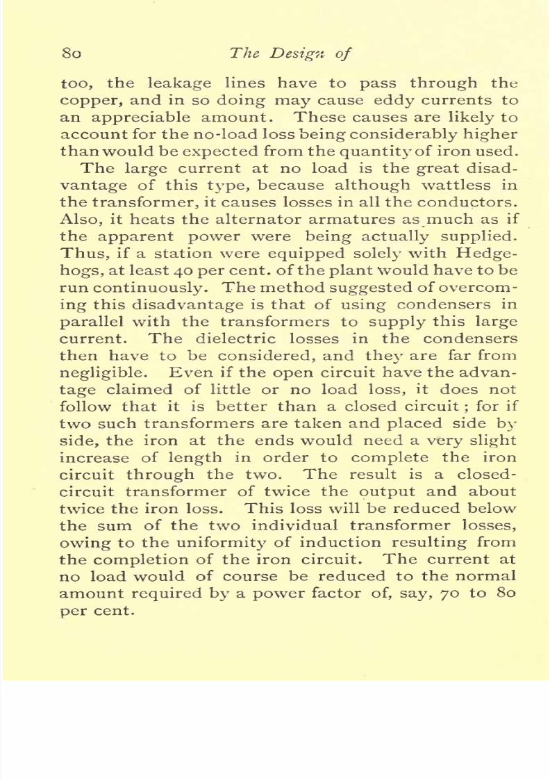
8/20/2019 ac transformer.pdf
http://slidepdf.com/reader/full/ac-transformerpdf 84/120
80
The
Design
of
too,
the
leakage
lines
have
to
pass
through
the
copper,
and
in
so
doing
may
cause
eddy
currents
to
an
appreciable
amount.
These
causes
are
likely
to
account
for
the no-load
loss
being considerably
higher
than
would
be
expected
from
the
quantity
of
iron used.
The
large
current
at no
load
is the
great
disad-
vantage
of
this
type,
because
although
wattless
in
the
transformer,
it
causes
losses
in
all
the
conductors.
Also,
it
heats
the
alternator armatures
as
much as
if
the
apparent
power
were
being
actually
supplied.
Thus,
if
a
station
were
equipped
solely
with
Hedge-
hogs,
at least
40
per
cent,
of
the
plant
Would
have
to be
run
continuously.
The method
suggested
of overcom-
ing
this
disadvantage
is
that
of
using
condensers
in
parallel
with the transformers
to
supply
this
large
current.
The
dielectric losses
in
the
condensers
then
have to
be
considered,
and
they
are
far
from
negligible.
Even
if
the
open
circuit
have
the advan-
tage
claimed
of
little or no
load
loss,
it
does not
follow
that
it
is
better
than
a
closed
circuit
;
for
if
two
such
transformers
are taken
and
placed
side
by
side,
the
iron
at the ends
would
need
a
very slight
increase
of
length
in
order
to
complete
the
iron
circuit
through
the
two.
The
result
is
a
closed-
circuit
transformer
of
twice
the
output
and
about
twice the
iron
loss.
This
loss will
be
reduced below
the
sum
of
the two
individual
transformer
losses,
owing
to
the
uniformity
of
induction
resulting
from
the
completion
of the
iron
circuit.
The
current
at
no
load
would
of
course
be reduced
to
the normal
amount
required
by
a
power
factor
of,
say,
70
to
80
cent.

8/20/2019 ac transformer.pdf
http://slidepdf.com/reader/full/ac-transformerpdf 85/120
Alternate Citrrent
Transformers.
81
Large
transformers
are
expected
to
be
more efficient
than
small
ones,
but
still
the
combination
thus
made
will
show
at once
the
advantage
of
having
a closed
core.
Magnetic
Leakage
of
Transformers.
This
branch
of the
subject
is
one
that cannot be
satisfactorily
treated
by
calculation
alone,
and
even
when
aided
by previous
experiments
it is
not
easy
to
predict
accurately
the
leakage
effects
in a
new
design.
When
a
transformer
is
working
a
full
load,
the
internal
reactions
cause fewer
lines of
force to
pass
through
the
secondary
than
through
the
primary,
and
hence
we find
a
larger
drop
of volts than can be
accounted
for
by
loss in
the
copper.
It
is
usual
to
deduct
the
known C
R
losses,
and
to call
the
remaining drop
in
pressure
magnetic
leakage.
When
a
transformer
is
working
light
the
primary
supplies
the
current
necessary
to
magnetise
the core
and
the
secondary
has
no
current
in
it,
hence the
action
is
simple
and
there
is
no
differential
magnetising
effect.
Now
at
full
load
in the
third
design
the
primary
current
has
increased
to
26*5
times its
previous
value,
and we
have
the
secondary
current
opposing
the
magnetising
force of
the
primary.
At no
load,
the
magnetising
force
just
inside the
primary
due
to
v
('0864
ampere)
would
be
^-~
,
where
r
=
the
turns
per
coil,
and
/
=
the
length
of the
coil.
TT 0864
x
865
x
1-76
-'.H--
I
'
=
5-6
in
C.G.S.
measure.
o
o
that
the
in
the
air

8/20/2019 ac transformer.pdf
http://slidepdf.com/reader/full/ac-transformerpdf 86/120
82
The
Design
oj
small
i.e.,
5-6
compared
to
that
in
the iron.
At
full
load
the
current
rises
to
three
amperes
;
so
the
magnetising
force in the air
space just
inside
the
primary
will
now
be
=
195'
FIG.
24.
This will
give
an induction
of
195
lines
per
centi-
metre,
which,
when
multiplied by
the
area,
gives
a
leakage
flux
which
is
appreciable.
The
action
is not
confined
to
the
actual
space
between
the
windings,
but
extends
into the
wire.
in
Fig.
the
values
of
H
are
plotted
over

8/20/2019 ac transformer.pdf
http://slidepdf.com/reader/full/ac-transformerpdf 87/120
Alternate
Current
Transformers.
83
a
section of
the
winding
space.
The
magnetising
force
rises
to
its
maximum
value
just
inside
the
primary winding,
and
maintains
this value
till
the
secondary
current
causes it
to
fall.
Halfway
through
the
primary
the
force
will
be half
the
maximum,
but
as
half
the
turns
only
are
cut
by
the
leakage
lines
generated
here,
the
effect,
if
considered as
acting
on
the
whole
number
of
turns
in
the
primary,
will
be
represented
by
half
the
ordinate
at
this
point.
Proceeding
in
this
way,
we
get
the
total
equivalent
leakage
effect,
each
point
which
is
represented
graphically
by
the
curve
lying
under
the
lines,
a,
b,
c,
d.
The
area
included
between
this
curve
and
the
abscissa,
a,
f,
represents
the
total
leakage
flux
when
multiplied
by
the
mean
perimeter
and constants
depending
on the
scale
to
which
the curve is
drawn. This
figure
represents
the
number of
C.G.S. lines
which
are
acting
on
the
primary
only.
It
will
be
found
that
the flux
thus
obtained
is
a
larger
percentage
of
the
total
flux
than
the
drop
due to
magnetic
leakage
is of
the total
voltage.
This is because the
leakage
field
thus
summed
up
is
in
quadrature
with
the
induction
in
the
iron.
Hence
its
effect
must
be
worked out
as
acting
at
right
angles
to
the
flux
in
the iron.
When
this
has
been
done,
an
approximate
figure
will
be
obtained
generally
under-estimating
the
leakage,
because
no notice has been taken of
the return
path
of these
leakage
lines.
With
careful
considera-
tion of all
these
points,
it
is
possible
to obtain
a
fair
approximation
to
the
leakage
effect,
but when
on
one
are
more

8/20/2019 ac transformer.pdf
http://slidepdf.com/reader/full/ac-transformerpdf 88/120
84
The
Design of
valuable.
It
is
better
in
working
out
transformers
to
obtain the
number
of
ampere-turns
per
given
length
of
leakage
path,
and then
by
comparison
with
previous
experiments
to determine the
prob-
able
leakage
effects.
When
measuring
the
mag-
netic
drop, great
care
must
be
taken that the
circuit used
for
the
load
has neither induction
nor
capacity
in
it.
Otherwise
the
results
will
be
practi-
cally
useless.
Very
little
capacity
will
completely
annul
the
drop
and,
on
the other
hand,
induction
increases it.
In
connection
with
leakage
it
must be
clearly
remembered
that
it is
only
alteration
in
magnetic
flux
due
to
the
secondary
current
that
causes
bad
regulation.
Leakage
of
the
induction
in
the
core
across
to
the
yokes,
such as is
found
in
all
magnetic
circuits,
has
no
harmful
effect on
the
regulation.
Thus the
Hedgehog
transformer
virtually
has the
return
path
of the
magnetic
lines
as
leakage,
and
yet
it
regulates
as
well or better
than
many
closed
circuits.
This is due
to
the
fact
that
the
differences
between the
magnetising
force of
the
primary
at
no
load
to
its
value
at full
load
is
nearly
3
to
i
instead
of
26 to
i,
as
in
the
transformer
above.
This
leakage,
which
does
not
affect
the
regulation,
may,
however,
be
very
harmful
in
causing
eddy
currents
in
both iron
and
copper,
and
a
Hedgehog
trans-
former
made
with
a
core
of
iron
plates
would
show
this
at once
by
giving
a
larger
iron
loss than
with
the
wire
core.
Alteration
of
Efficiency
with
Frequency.
The selec-
tion
of
the most
economical
for
alternate-
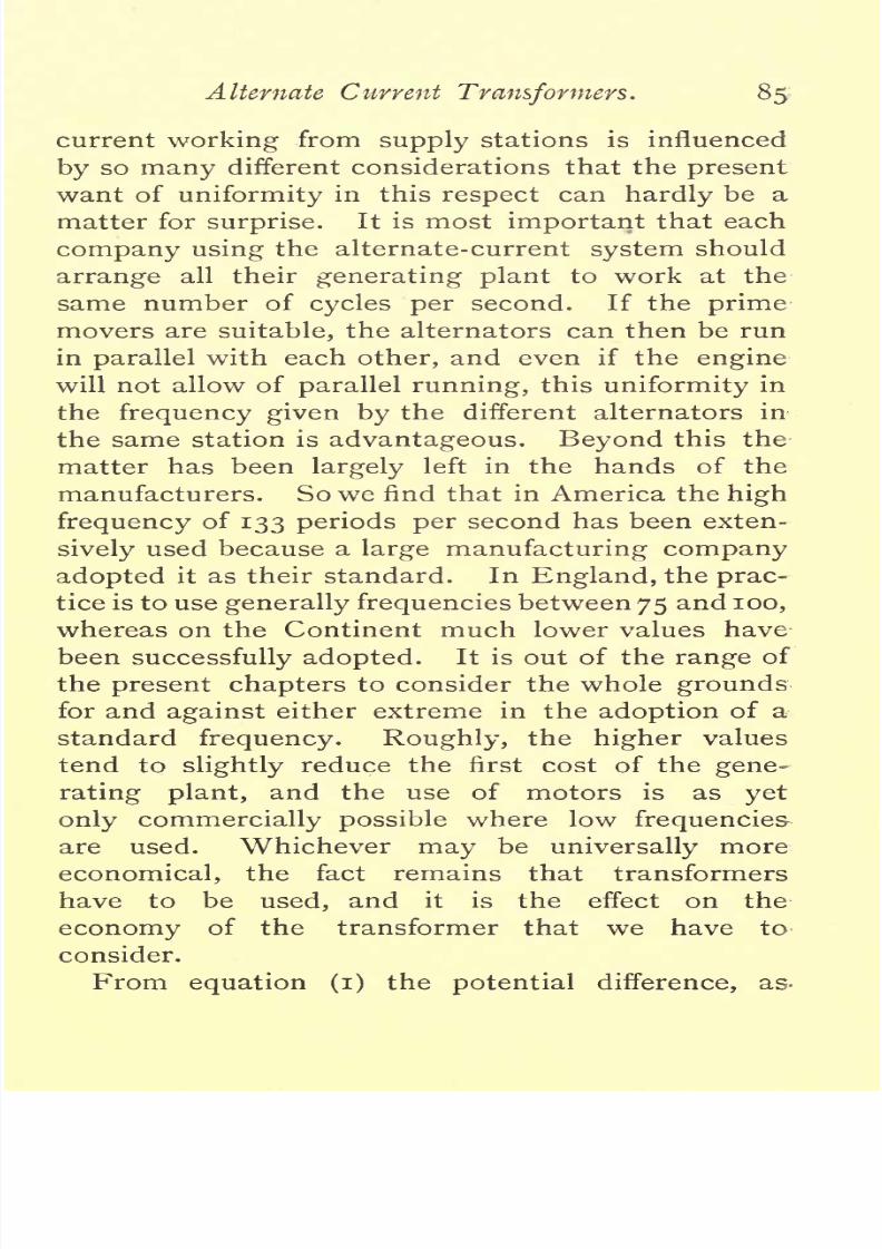
8/20/2019 ac transformer.pdf
http://slidepdf.com/reader/full/ac-transformerpdf 89/120
Alternate Current
Transformers.
85
current
working
from
supply
stations is influenced
by
so
many
different
considerations
that
the
present
want of
uniformity
in
this
respect
can
hardly
be a
matter for
surprise.
It
is
most
important
that each
company
using
the alternate-current
system
should
arrange
all their
generating
plant
to
work
at
the
same
number of
cycles
per
second.
If the
prime
movers
are
suitable,
the
alternators
can then
be
run
in
parallel
with each
other,
and even
if
the
engine
will not
allow of
parallel
running,
this
uniformity
in
the
frequency
given
by
the
different alternators
in
the
same
station
is
advantageous.
Beyond
this
the
matter
has
been
largely
left
in
the hands of the
manufacturers.
So
we
find
that
in
America
the
high
frequency
of
133
periods per
second has been exten-
sively
used because
a
large
manufacturing company
adopted
it
as
their standard.
In
England,
the
prac-
tice
is
to use
generally
frequencies
between
75
and
100,
whereas
on
the
Continent
much
lower
values
have
been
successfully
adopted.
It
is
out
of
the
range
of
the
present
chapters
to
consider the
whole
grounds
for and
against
either
extreme
in
the
adoption
of
a
standard
frequency.
Roughly,
the
higher
values
tend
to
slightly
reduce
the
first
cost
of
the
gene-
rating plant,
and
the use
of
motors
is as
yet
only
commercially
possible
where
low
frequencies
are used.
Whichever
may
be
universally
more
economical,
the
fact
remains
that
transformers
have
to
be
used,
and
it
is
the
effect on
the
economy
of the transformer that
we have
to
consider.
(i)
the
potential
difference,
as-

8/20/2019 ac transformer.pdf
http://slidepdf.com/reader/full/ac-transformerpdf 90/120
86
The
Design
of
measured
by
a
Cardew
voltmeter,
at the terminals
of
a
transformer
on open
circuit
is
e
=
4*45
F
r
n
io~
s
,
and
F,
the
total
flux,
may
be
written
|i
a
where
|$
equals
the maximum
induction,
and
a
equals
the
cross-section
of
the iron core.
Hence,
e
=
4-45
^
am
io~
8
With
a
transformer
having
a
certain
transforming
ratio,
say,
2,000/100
volts,
the
voltage,
e,
required
on
the
secondary
will be
the
same
whatever
the
frequency
of the
alternating-current
supply.
This
ensures
that
e
shall
be
a
constant
quantity
however
the
frequency
may
vary
on
different
supply
mains.
We
may
therefore
consider e
as
constant,
and
the
quantities
a and
T
on the
other side are
also con-
stants
for
any
given
transformer.
Hence,
if n
changes,
there
must
be
an
inverse
change
in
?
to
keep
the
E.M.F.
up
to
the
same
value,
or,
in
other
words,
n
=
I
M
I>
where
1%
are
the
new values
of
the
induction
and
frequency
respectively.
Hence,
in the
transformers
designed
above
for
100^^
the
induction
required
would
be
doubled if
the
frequency
were
dropped
to
50^^-.
This
alteration in
induc-
tion
alters
the
value
of
the
iron
losses,
and
hence
affects
the
efficiency
of the
transformer.
The
subject
of the
loss
in
iron
wire
and
plates
when
subjected
to
a
magnetising
force
which
varies
has
been
a
source
of
many
investigations
of
late
years.
The
conclusions
arrived
at
by
the
many
able
on
this
subject
are
:
first,
that
the

8/20/2019 ac transformer.pdf
http://slidepdf.com/reader/full/ac-transformerpdf 91/120
Alternate Current
Transformers.
87
hysteresis
loss
in
the
iron
for
any
given
induction
is
directly
proportional
to
the
number
of
reversals
;
second,
from
the
many
curves
obtained
it is found
that the
results
are
fairly
represented
by
an
equation
containing
IP
to the r6th
power.
Hence the loss
in
hysteresis
only
may
be
expressed
by
the
equation
:
W*=anW
....
(5)
where
W
H
= the
watts
lost
per
pound
of iron
;
a is
a
constant
depending
on
the iron
used
;
n
=
the
frequency
;
IP
=
the
maximum
induction.
The other
part
of
the
iron
loss
is
that
due
to
Foucault
currents
in
the iron
plates.
The determination of
formulas
for
calculation of
these losses
in
plates requires
some
elementary
calculus,
and certain
assumptions
as
to
the
path
taken
by
the
current
have
to
be
made.
It
will
be
sufficient
to
take
the
generally
accepted
formula for
iron
plate,
which,
when
reduced to
watts
per
pound
of
iron,
becomes,
roughly,
W
F
=
5 (r$n)
2
io-
9
...
(6)
at
loodeg.
F.,
where
t
=
the thickness
of
the
plate
in
inches
and
|p
and
n
have
values
as
above.
Now,
for
any given
transformer
the
square
of the
thick-
ness
of
the
plates
may
be
merged
into
the
constant,
and the formula becomes
W
F
=
b
($
)2,
where
b
is
a
constant.
Hence
the
total
loss
is
given by
W
H
+
W
P
=
anW
Q
+
b
(wf)
2
.

8/20/2019 ac transformer.pdf
http://slidepdf.com/reader/full/ac-transformerpdf 92/120
88
The
Design
of
As
n
occurs
in
different
powers
in
the
two
terms
on
the
right-hand
side
of
this
equation,
it
will
be
readily
seen that
any
curve
drawn
for the
total
iron
losses
for
a
given
frequency
cannot
be
used at
any
other
frequency.
It
is,
however,
quite possible
by
careful
experiments
to
verify
the
equation
given
above. This can
best
be
done
by taking
power
readings
of
the
iron
losses
when
the
frequency
is
varied
very
considerably.
Then
the
different
set of
results
can
be
analysed
by
simple
algebra.
This can
be more
readily
done with
plates
of
greater
thickness
than
those
used
in
ordinary
work,
as
in
that case
the
expression
for the
eddy
currents
is a
larger pro-
portion
of
the
total
loss.
The
approximate
truth
of
this
formula
and the
corresponding
expression
for
the
eddy-current
loss
per
pound
of
iron
being
established,
we
can
proceed
to divide the curve
of
iron
losses,
Fig.
4,
into its
two
components.
To do
this,
the
loss
in
foucault
currents
in
watts
per
pound
for
inductions
varying
from
|i
=
8,000
to
|i
=
1,000
must
be calculated from
(6),
and
the
figures
obtained
when
subtracted
from
the
ordinates of
curve,
Fig.
4,
leave the
hysteresis
loss
per
pound
at 100
cycles
per
second.
Thus
at
=
6,000
for
lo-mil
plates
we
have
W
F
=
5
(*?M
2
io-
9
=
5
x
('oi
x
6,000
x
ioo)
2
x
io~
9
=
5
x
6,OOO
x
6,OOO
x
IO~
9
=
*i8o
watt
per pound.
Now
the
ordinate
on
Curve
4
when
=
6,000
is
1*70.
Therefore
the
hysteresis
loss
alone
is
1*70
-
18
=
1*52
watts
of
iron.
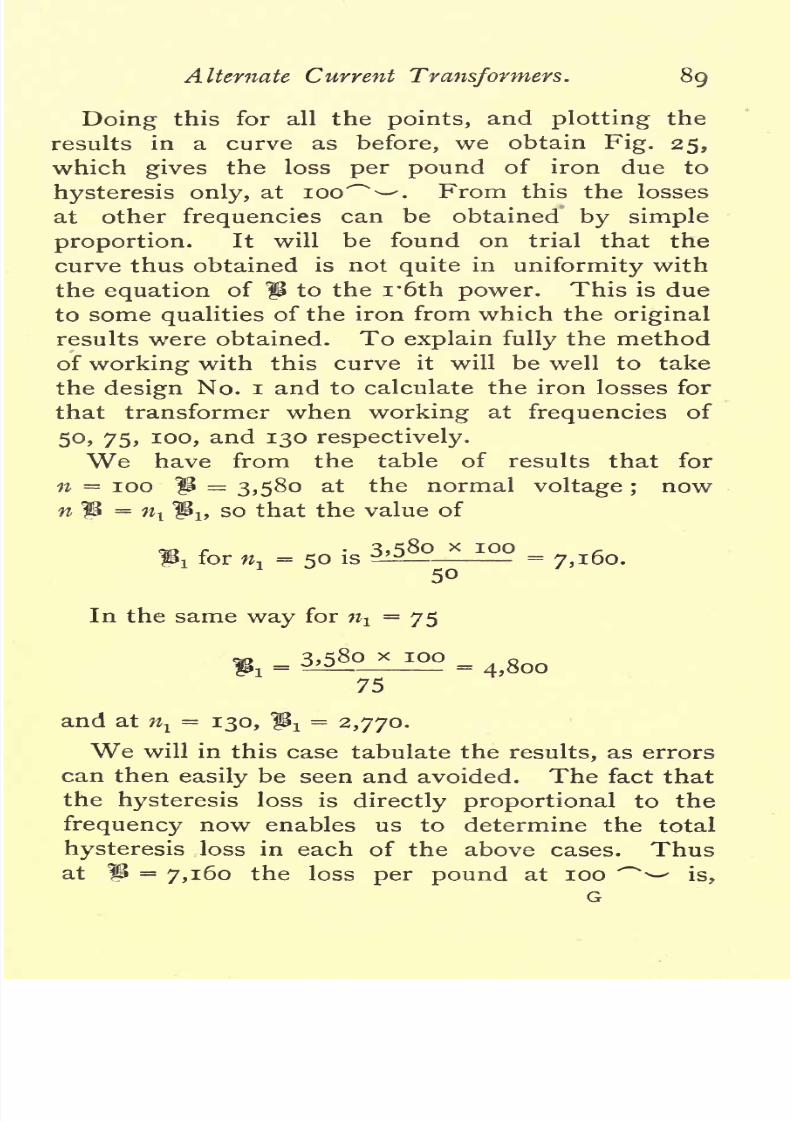
8/20/2019 ac transformer.pdf
http://slidepdf.com/reader/full/ac-transformerpdf 93/120
Alternate
Current
Transformers.
89
Doing
this
for
all
the
points,
and
plotting
the
results
in
a
curve
as
before,
we
obtain
Fig.
25,
which
gives
the
loss
per pound
of
iron
due to
hysteresis
only,
at
100^
'. From this
the losses
at other
frequencies
can be
obtained
by
simple
proportion.
It
will
be found on
trial that
the
curve
thus
obtained
is
not
quite
in
uniformity
with
the
equation
of
|i
to
the
i*6th
power.
This
is
due
to some
qualities
of
the iron
from
which the
original
results
were obtained.
To
explain
fully
the method
of
working
with
this
curve
it
will
be
well to take
the
design
No.
i
and
to
calculate the iron losses for
that transformer when
working
at
frequencies
of
50,
75,
100,
and
130
respectively.
We
have from the
table of
results
that
for
n
=
100
IP
=
3,580
at
the
normal
voltage
;
now
n
IP
=
w
t
IPu
so
that
the
value
of
fc
for
^
-
50
is
3.580JLI2?
=
7,160.
In
the same
way
for
n^
=
75
x
IOQ
=
4,800
75
and at
^
=
130, ^
=
2,770.
We
will
in
this
case
tabulate
the
results,
as
errors
can then
easily
be seen
and avoided. The fact
that
the
hysteresis
loss
is
directly proportional
to
the
frequency
now
enables
us
to determine
the
total
hysteresis
loss
in
each
of the
above
cases.
Thus
at
^
=
7,160
the
loss
per pound
at
100
^^
is,

8/20/2019 ac transformer.pdf
http://slidepdf.com/reader/full/ac-transformerpdf 94/120
go
The
Design
of
from
Fig.
25,
1*94
watts
per pound.
Therefore
the
loss
at
50
^^-
in
ij2'$lb.
will
be
AT
T
1*04
x
172*5
x
50
\V
H
=
^
=
1
68
watts.
100
TABLE
OF
IRON
LOSSES
AND
NO-LOAD
CURRENTS
FOR
SHELL
TYPE
SIX-KILOWATT TRANSFORMER
(DESIGN i)
AT
DIFFERENT
FREQUENCIES.
In
the
same
way
for
|p
=
4,800
and
n
=
75,
WH
=
ri25
X
I72
'
5
X
75
=
146
watts.
IOO
The rest
of the values
of W
H
calculated
in
the
same
way
are
133*8
for
n
=
100,
and
124
watts
for
n=
130.
The Foucault
loss is
got
from
the formula
(6)
i.e.,
watts
per
pound
=
5
(t
n)
2
io~
9
.
In
this
transformer
lo-mil
plates
were
used,
and
the iron
weighed
172*5^.
Hence,
W
P
=
172*5
x
5
x
(
f
oi
x
7,160
x
50)2
x
io~
9
.
=
11
watts
at
50
frequency.
saw above
that
n was
a
constant

8/20/2019 ac transformer.pdf
http://slidepdf.com/reader/full/ac-transformerpdf 95/120
Alternate
Current
Transformers. gi
if
the
voltage
at the
terminals of the
transformer
was
not
varied.
So
the
eddy-current
loss
must
also
be
a
constant
for
all
frequencies,
as
these
two
quan-
tities are the
only
variables
in
the
equation
used
above.
Filling
up
the
list,
the
total
iron
loss in
each
case can now
be
obtained
by
addition.
It
will
be
immediately
observed
that
this increases
rapidly
with
a
decrease
of
the
frequency.
By
halving
the
value
of
n,
we
have
in
this
transformer
increased
the
iron
losses
by
some
25
per
cent.
Hence,
if
the
transformer
was
designed
to the
heating
limit at
a
frequency
of
100,
it
would
get
too
hot
when
placed
on a
circuit
supplied
at
50
frequency.
This
change
in
the
iron
loss is
more
marked
in
transformers
using
a
higher
induction than
in
the
present
design.
To
complete
the
list,
we
now
require
to
find
the
exciting
current
at
the
different
frequencies.
The
values
of

8/20/2019 ac transformer.pdf
http://slidepdf.com/reader/full/ac-transformerpdf 96/120
9
2
The
Design of
/JL
for
each
induction
can be
at
once
taken
from
the
curve
Fig.
5.
Then
i^
from
(2)
=
-
?
_
.
As
JUL
TI
x
176
four
values
have
to
be
calculated
and
part
of
the
right-hand
side,
-
,
is
common
to all
cases, it
TI
x
176
may
conveniently
be
worked
out
separately.
In
this
transformer,
/,
the mean
length
of
the
iron
circuit
was
I23cm.
and
TI
=
1,490
therefore
-
=
'0468
;
T
x
176
Ig
and
iu
=
x
-0468.
ft
Thus
at
n
=
50,
IP
=
7,160,
and
/UL
=
2,650,
...
i,
=
Zil6o
x
8
2,650
=
'127
ampere.
The
rest can
be
worked out
in
exactly
the same
way.
The
values
of
i
n
are
obtained
by
dividing
the total
iron
loss
by
the
voltage
on
the
primary winding,
which
in
this case
was
2,000.
The
magnetising
current
i
*/i
R
2
+
v
2
?
s
m
the
first
case
i
=
J'oSg
2
x
-1272
=
-155
ampere.
Completing
the
other
values
in
the same
way,
it
will
then
be better
for reference
to add
two
more
lines,
the
iron
loss
current

8/20/2019 ac transformer.pdf
http://slidepdf.com/reader/full/ac-transformerpdf 97/120
Alternate
Current
Transformers.
93
respectively
in
percentages
of the full-load values.
The
ratio
of
these
two
gives
the
power
factor,
which
will
be
seen to
fall
with
the
frequency.
This is
not
always
so,
but
depends largely
on
the
shape
of the
IJL
curve
of
the
iron
used.
The
general
conclusions
from this
investigation
are
briefly
as
follows
:
When the
frequency
at which
the
transformer
is
used
is
decreased,
the
loss in
iron
is
increased,
and there is
consequently
a fall
in the
efficiency
of
the
transformer.
(It
must
be
remem-
bered
when
considering
the loss
in
the
iron
of a
transformer,
that
although
the loss
may
be
a
com-
paratively
small
percentage
of
the
maximum
output,
it
is
a
large
percentage
of
the
average
load.
Thus,
while
an increase of
25
per
cent.
i.e.,
from
2*42
to
2*98 per
cent.
does not
appear
much,
it
may
make
the
difference
between
profit
and no
profit
in
the
central-station
accounts.)
Also
the
larger
iron loss
will increase
the
final
temperature
of the
trans-
former.
So,
for
low
frequencies,
more
cooling
surface should
be
provided.
In
other
words,
a
larger
transformer
is
required.
This,
of
course,
will
raise the
cost
of
the
instrument
for
a
given
output.
On
the
other
hand,
a
transformer
designed
to have
a
good
efficiency
at
a
low
frequency
can
be
used
more
economically
at
higher
frequencies,
but
the cost of manufacture will then be
the
prohibitive
factor.
Quality
of
Iron.
This
is
the
indeterminate
quantity
which causes
uncertainty
in
the
manufacture
of
transformers.
Every
batch
of iron
received
should
separate,
test
of

8/20/2019 ac transformer.pdf
http://slidepdf.com/reader/full/ac-transformerpdf 98/120
94
The
Design of
made
from it
then
give
a
ready
check on
any
falling
off
in
the
quality.
The
curves
given
(Figs.
4
and
5),
which have been
used
in all
the
designs
above,
were
taken
from
a
transformer
actually
made.
The iron
was
a
better
quality
than the
average
brands
of
plate,
but
was
by
no
means the
best that can
be
obtained.
With
careful
selection,
iron can
be
found
with
which
the
losses
per
pound
come
out
quite
30
per
cent,
below those
given
in
Curve
4.
It
is
in
the
permeability
curve
that the
greater
difference
is
noted with-
these
superior
qualities
of
iron.
This
curve,
then,
rises
much
more
rapidly
at low induc-
tions,
and
the
permeability
throughout
may
be
some
80 per
cent,
higher
than
the values
given
in
Curve
5.
The
higher
permeability
reduces
the
current
re-
quired
to
magnetise
the
iron,
and
consequently
the
power
factor is increased.
On
referring
to
Dr.
Fleming's
list
of
tests,
it will
be seen
that
in one
case he obtained
a
power
factor
as
high
as
92.
A
special
brand
of
mild
steel
is
said to
be
used
in this
transformer,
which
must have
a
very
high
per-
meability
to
account
for
such
a
power
factor.
Transformers
for
Different
Methods
of Supply.
The
transformers used
in
lighting
individual
houses
are
very
seldom
worked
at full
load,
and
the
average
load is so small that the
heating
effect
of the current
in
the
copper
circuit
may
be
almost
neglected.
The
transformer
should,
of
course,
be
able
to
stand the
full
current
for
some
hours without
undue
rise of
temperature.
The
all-day
efficiency
is
then fixed
by
the iron
loss,
and
the
copper
be
reduced
to
save first
cost
if
the
reduc-

8/20/2019 ac transformer.pdf
http://slidepdf.com/reader/full/ac-transformerpdf 99/120
Alternate
Current
Transformers.
95
tion
in
section
did not also affect
the
regula-
tion.
The
sub-station
system
of
supply
is
now
coming
into
more
general
use. In
this
system
the
consumers are
connected
on
to a
low-
tension
network,
which
is fed at
different
places
by
transformers
in
sub-stations.
In
this
way,
even
if
the
whole
of the
transformers
are
left
continuously
on
the
mains,
a
much
higher
load
factor
is
obtained,
owing
to the
different
classes
of
buildings
supplied.
That
is
to
say,
the
average
load
is a
larger propor-
tion of
the
maximum
load,
and
hence the
trans-
former is
worked
more
economically.
To
still
further increase
the
economy,
arrangements
are
made
for
reducing
the
number
of
transformers
in
connection with the main as
the load diminishes.
So
in
these transformers
and
in
those
used in
power
transmission on a
large
scale,
the
watts wasted
in
the
copper
form a
good
proportion
of the total
loss.
As
the
heat
generated
in
the
copper
is
liable
to
hurt
the
insulation,
it
is
advisable
in
the
large
trans-
formers
used for
central-station work
to
keep
the
percentage
loss
in
the
copper
lower
than in
small
transformers for
separate
installation work.
THE END.

8/20/2019 ac transformer.pdf
http://slidepdf.com/reader/full/ac-transformerpdf 100/120

8/20/2019 ac transformer.pdf
http://slidepdf.com/reader/full/ac-transformerpdf 101/120
The
Electrical
Engineer
WITH
WHICH IS
INCORPORATED
ELECTRIC
LIGHT.
Edited
Iby
C.
H.
1HT.
BIGGS,
Assisted
by
Messrs.
H.
SWAN,
F.
B.
LEA,
and
A.
WILLBOND.
*
THE
ELECTRICAL ENGINEER
claims
to be
the
most
practical
and
the
earliest-informed
paper
on all
questions
relating
to
Electric
Lighting,
and
especially
Municipal
Lighting,
as
well
as
on
all
that
relates
to
the
Distribution
and
Application
of
Electric
Power to
all
purposes.
This
paper
was
the
first
to
make
English
readers
acquainted
with
the
three-phase
system
of
distribution,
the construction of
incandescent
lamps,
the
construction
of
alternate-current
transformers,
and has
fully
described
and
illustrated
the
various
systems
of
practically
laying mains.
Every
effort
is
made to
keep
readers
fully
acquainted
with
all
progress
in
electrical
matters.
It is the best technical
paper
for
young
electrical
engineers.
It
aims
at
and
succeeds
in
giving early
and
accurate
information
about
all that
concerns
the
industry,
and
is
absolutely
free
from
any
outside
control.
It
is
an excellent
advertising
medium.
Every
Friday.
Price
Threepence,
k.XXVXXXXXVXXWXWXX'V

8/20/2019 ac transformer.pdf
http://slidepdf.com/reader/full/ac-transformerpdf 102/120
PRACTICAL
ELECTRICAL
ENGINEERING.
Being
a
complete
treatise on
the
Construction
and
Management
of Electrical
Apparatus
as used
in
Electric
Lighting
and
the Electric Transmission
of
Power.
2
Yols,
Imp.
Quarto.
BY
VAKIOUS AUTHORS.
With
many
Hundreds
of
Illustrations.
PRICE
2 2s. Od.
Among
the
information collected in and
written
specially
for
these
volumes,
are
complete monographs by
MR.
GISBERT
KAPP,
M.
Inst. C.E.
on
Dynamos,
giving
the
principles
on
which
the
construction
of
these
machines
is
founded,
and a vast amount of new information
as
to
the
constructive
details.
MR,
ANTHONY
RECKENZAUN,
M.
Inst.
E.E.
considers
the
whole
question
of
Electric
traction on
Railways
and
Tramways,
describing
the most
recent
practice
and
giving
exhaustive
details
not
only
of the
mechanism,
but
of
practical
considera-
tions
which
are
of
the
utmost
commercial
importance.
MR.
C.
CAPITO,
M.
Inst. E.E.
deals
with
steam and
considers
the
theory
as
well
as
the
practical
construction
of
boilers
and
engines,
more
especially
in
connection
with
Electric
lighting
and transmission of
power.
This
section alone
con-
tains no
less
than
371
illustrations.
MR.
HAMILTON
KILGOUR
considers
carefully
the
theory
of
Elec-
trical
distribution
upon
which
depends
the
right
proportioning
of
mains in
order
to
secure
economical
distribution.
Other
men have
collected
a
complete description
of
the various
systems
practically
applied,
the
materials used
and
methods
of construction.
The
above
form but
a
portion
of these
volumes,
but
should
prove
of
the
utmost value
to
every
one
who
professes
to be
an

8/20/2019 ac transformer.pdf
http://slidepdf.com/reader/full/ac-transformerpdf 103/120
DYNAMOS,
ALTERNATORS,
AND
TRANSFORMERS
BY
GISBERT
XAPP,
M.Inst.C.E.,
M.Inst.E.E.
ILLUSTRATED.
PRICE
10s. 6d.
The
book
gives
an
exposition
of the
general
principles
underlying
the
construction
of
Dynamo-Electric
Apparatus
without
the
use of
high
mathematics
and
complicated
methods of
investigation,
thus
enabling
the
average
engineering
student
and
the
average
electrical
engineer,
even
without
previous
knowledge,
to
easily
follow the
subject.
CHAPTER
I.
Definition.
Efficiency
of
Dynamo-Electric
Apparatus.
Measurement
of Electric
Energy.
Principal
Parts
of
Dynamo.
Distinction
between
Dynamo
and
Alternator.
Use
and
Power
of
these
Machines.
CHAPTER
II.
Scope
of
Theory.
The
Magnetic
Field.
Strength
of
Field. Units
of Measurement.
Physical
and
Mathematical
Magnets.
Field of
a
Mathematical
Pole.
CHAPTER
III.
Magnetic
Moment.
Measuring
Weak
Magnetic
Fields. Attractive Force of
Magnets.
Practical
Examples.
CHAPTER
IV.
Action
of
Current
upon
Magnet.
Field
of
a
Current.
Unit Current. Mechanical
Force between
Current
and
Magnet.
Practical
Examples.
English
System
of
Measurement.
CHAPTER
V.
The
Electromagnet.
The
Solenoid.
Magnetic
Per-
meability.
Magnetic
Force. Line
Integral
of
Magnetic
Force.
Total
Field.
Practical
Example.
Extension
of
Theory
to
Solenoidal
Electromagnets.
Magnetic
Resistance.
CHAPTER
VI.
Magnetic
Properties
of
Iron.
Experimental
Deter-
mination of
Permeability.
Hopkinson's
Method.
Energy
of
Magnetisation.
Hysteresis.
CHAPTER
VII.
Induced
Electromotive
Force.
Cutting
or
Thread-
ing
of
Lines. Value of
Induced
Electromotive
Force.
C. G.
S.
Unit
of
Resistance.
Fleming's
Rule.
Electromotive
Force
of

8/20/2019 ac transformer.pdf
http://slidepdf.com/reader/full/ac-transformerpdf 104/120
DYNAMOS Continued.
CHAPTER
VIII. Electromotive Force
of Armature.
Closed-Coil
Armature.
Winding.
Bi-polar
Winding.
Multipolar
Paral-
lel
Winding.
Multipolar
Series
Winding. Multipolar
Series
and Parallel
Winding.
CHAPTER
IX.
Open-Coil
Armatures.
The
Brush
Armature.
The
Thomson-Houston
Armature.
CHAPTER
X.
Field
Magnets.
Two-Pole
Fields.
Multipolar
Fields.
Weight
of
P'ields.
Determination of
Exciting
Power.
Prede-
termination
of
Characteristics.
CHAPTER
XL
Static
and
Dynamic
Electromotive
Force.
Com-
mutation of
Current.
Armature Back
Ampere-Turns.
Dyna-
mic
Characteristic.
Armature
Cross
Ampere-Turns.
Spark-
less
Collection.
CHAPTER
XII.
Influence
of Linear
Dimensions
on
the
Output.
Very
Small
Dynamos.
Critical
Conditions.
Large
Dynamos.
Limits
of
Output.
Advantage
of
Multipolar
Dynamos.
CHAPTER
XIII.
Loss of
Power
in
Dynamos.
Eddy
Currents in
Pole-Pieces.
Eddy
Currents
in
External
Conductors.
Eddy
Currents
in
the
Armature
Core.
Eddy
Currents in
the
Interior
of
Ring
Armatures.
Experimental
Determination of
Losses.
CHAPTER
XIV.
Examples
of
Dynamos.
Ronald
Scott's
Dynamo.
Johnson
and
Phillips's
Dynamo.
Oerlikon
Dynamo.
Other
Dynamos.
CHAPTER
XV.
Elementary
Alternator.
Measurement
of Electro-
motive
Force.
Fawcus
and
Cowan
Dynamo.
Electromotive
Force
of Alternators.
Self-induction
in
Armatures
of
Alter-
nators.
Clock
Diagram.
Power
in
Alternating-Current
Circuit.
Conditions
for
Maximum
Power.
Application
to
Motors.
CHAPTER
XVI.
Working
Conditions.
Effect
of
Self-induction.
Effect
of
Capacity.
Two
Alternators
Working
on Same
Circuit.
Armature Reaction.
Conditions
of
Stability.
General
Conclusions.
CHAPTER
XVII.
Elementary
Transformer.
Shell
and
Core
Type.
Effect
of
Leakage.
Open-Circuit
Current.
Working
Dia-
grams.
CHAPTER
XVIII.
Examples
of
Alternators.
The
Siemens Alter-
nator.
The
Ferranti Alternator.
Johnson
and
Phillips's
Alternator.
The
Electric Construction
Corporation's
Alter-
nator.
The
Gulcher
Company's
Alternator.
The
Mordey

8/20/2019 ac transformer.pdf
http://slidepdf.com/reader/full/ac-transformerpdf 105/120
ELECTRICAL
DISTRIBUTION
ITS
THEORY
AND
PRACTICE.
PART
I.
BY
MARTIN
HAMILTON
KILGOUK.
PART
II.
BY
H.
SWAN
&
C. H.
W.
BIGGS.
10s.
6d.
PART
I.
'CHAPTER
I.
Introduction.
CHAPTER
II.
Constant Current
(Series)
System.
Constant
Current
(Parallel) System.
Feeders.
Distributing
Mains.
Supply
to
Apparatus
at
a
Variable
Distance
from
the
Generating
Source.
CHAPTER
III.
Economy
in
Design.
Supply
to
Apparatus
at a
Constant
Distance
from
the
Generating
Source.
<
CHAPTER
IV.
Miscellaneous
Problems
on
Feeders.
Distributing
Mains.
CHAPTER
V.
Hypothesis.
Calculations, Tables.
CHAPTER
VI.
Examples.
Tables
of
Square
Roots. Particulars
of
Conductors.
PART
II.
CHAPTER
VII.
Bare
Wire
and
Modification
of
Bare
Wire.
Crompton's
System. Kennedy's System.
St.
James'
and
Pall
Mall.
Tomlinson's
System.
CHAPTER
VIII. Practise
in
Paris.
Compagnie
d'Air
Comprime
et
d'Electricite.
Continental
Edison.
Soci6te
du
Secteur
de
la
Place
Clichy.
Secteur
des
Champs
Elysees.
Halles
Centrales.
CHAPTER
IX.
Callender-
Webber
System.
Callender Solid
System.
CHAPTER X.
Brooks
Oil
Insulation
System.
CHAPTER
XI.
Ferranti
Concentric
Mains.
^CHAPTER
XII. Modified
Systems
Silvertown.
dt.
Pancras
Mains.
'CHAPTER XIII.
Johnstone's
Conduit
System.
CHAPTER
XIV.
Crompton
and
Chamen
with
Accumulators.

8/20/2019 ac transformer.pdf
http://slidepdf.com/reader/full/ac-transformerpdf 106/120
ELECTRIC
TRACTION
BY.
A.
RECKENZAUN,
M.I.E.E.
lO
This
is
the
first
serious
attempt
to
consolidate and
systematise
the
information
of
an
important
subject.
Mr.
Reckenzaun's
experience
is
of
the
longest
and
widest,
and
this
book
deals
not
only
with
the
scientific
and
practical problems
met
with
in
traction
work,
but enters
somewhat
into
the
financial
aspect
of the
question.
CHAPTER
I.
Early History.
Magnetic
Fields.
Torque.
Motor
Efficiency,
insulation
Resistance.
Brake
Tests.
Electri-
cal
Horse-Power.
CHAPTER
II.
Traction.
High
Pressure.
Current,
Stopping
and
Starting.
Current
Running.
Energy
Used.
CHAPTER
III.
Advantages
of Two
Motors on
Each
Car.
Calculations
for
Armatures.
Constructive
Details for
Motors.
Types
of
Tramcar Motors.
Method of
Suspen-
sion.
Brushes
and
Brush-holders
Switches
and
Speed-
Regulating
Devices.
Motor Trucks.
Important
Points
in
Tramcar
Motors.
Gearless
Motors.
Mechanical
Transmission
between
Motor
and
Axle.
CHAPTER
IV.
Description
of
Principal Systems
of
Overhead
and
Underground
Construction
used
in
Electric
Traction.
Poles.
Trolleys
and
Trolley
Wire.
Overhead
Curve
Construction.
Practical
Hints
on
Overhead
Construction.
Insulators
used
in
Electric
Railway
Work. Switchboards.
Lightning
Arresters
and
Cut-Outs.
CHAPTER
V.
Secondary
Batteries.
Weight
and
Efficiency
Deterioration.
CHAPTER
VI.
Portrush,
Bessbrook-Newry,
City
and
South
London
Railways.
Central
London
Railway, Blackpool,
Budapest,
Leeds,
and
Halle Electric
Tramways,
West
End
Railway,
Boston.
CHAPTER
VII.
Resume
of
Writings
and
Expressions
of
Prom-
inent
Electrical
Engineers
on
Electric
Traction.
CHAPTER
VIII. Details
of
Working
Expenses.

8/20/2019 ac transformer.pdf
http://slidepdf.com/reader/full/ac-transformerpdf 107/120
SECONDARY
BATTERIES.
BY
J.
T.
NIBLETT.
ILLUSTRATED.
PRICE
3s.
This
little
treatise is an
attempt
to
bring
together
and
describe the
recent
commercial developments
of
Plante's
original
discovery,
the
Lead
Secondary
Battery.
CHAPTER
I.
Introductory.
CHAPTER
II.
Cells
of
PlantS
type
such
as
those
of
De
Meritens,
De
Kabath,
Reynier,
Montaud, Elwell-Parker,
Cheswright,
Epstein, Woodward,
Dujardin,
Dujardin-Drake-Gorham,
Crompton-
Howell.
CHAPTER III.
Pasted or
Faure
Storage
Cells,
such
as:
E.P.S.,
Eickemeyer,
Gadot,
Hagen,
Jacquet,
Pitkin-Holden, Ernst,
Payen,
Carpenter,
Bailey,
Knowles,
Laurent
-Cly,
Hering,
Tudor,
Pollak,
Gibson,
Frankland,
Currie,
Pumpelly,
Hatch,
Winkler,
Tommasi,
Bristol,
Lithanode.
CHAPTER
IV.
Lead-Zinc,
Copper,
Alkaline,
and
other batteries
such
as
Reynier,
Bailly, Hedges,
Lalande-Chaperon,
Thomson-
Houston,
Entz-Phillips,
Main, Barker, Kalischer,
Marx,
Taplow,
Osbo,
Jablochkoff.
CHAPTER
V.
The
Electrolyte,
etc.
Solid
Storage
Cells,
such
as,
Barber-Starkey,
Schoop,
Parker,
Volk,
Crova
and
Garbe,
Roux.
Spray.
CHAPTER
VI.
Appendix
Table for
the
conversion of
Measures,
Thermometric
Scales,
Lead and
its
Impurities,
Plumbic
Hydrates,
Sulphuric
Acid,
English
Oil of
Vitrol,
Electrical
Units,
Ohm's
Law,
Measuring
the
Internal
Resistance of
Voltaic
Cells,
Capacity
and
Efficiency
of
Storage
Cells,
etc.

8/20/2019 ac transformer.pdf
http://slidepdf.com/reader/full/ac-transformerpdf 108/120
PORTATIVE
ELECTRICITY.
BY
t
J.
T.
NIBLETT,
ILLUSTRATED.
PRICE
2s.
6d.
This
is
a
treatise
on
the
Application,
Method
of
Construction,
and
the
Management
of
Portable
Secondary
Batteries.
INTRODUCTION.
A brief
resum6
of Electrical
Discovery.
PART
I. Portative
Electricity
in
Mining Operations,
describing
some
of
the
Lamps
used,
and
Instruments for
the
Detection of
Dangerous
Gases.
Safety
Electric
Hand-lamps
for
Domestic
Purposes,
for
Customs'
Officers,
for
Meter
Inspectors,
and
for
Firemen.
Portative
Electricity
for
Domestic
Purposes,
for
Reading,
for
Driving
Motors,
for
Sterilising
Water.
Application
to
Medical
and
Scientific
Purposes.
Uses
for
Military
Purposes,
for
Land
Work,
At
Sea.
Uses
for
Lighting
Vehicles,
Railway
Carriages,
Omni-
buses,
Tramcars,
Broughams,
Cycles.
Traction
by
means
of
Portative
Electricity.
Applications
to
Decorative
Purposes,
for
Dinner
Tables,
Shop
Windows,
Fountains,
Jewellery,
on
the
Stage,
Personal
Adornment.
PART
II.
Secondary
Cells,
Plante's,
Crompton-Howell, Epstein,
D.
P.,
Faure,
E.
P.
S.,
Lithanode,
Pitkin,
Bristol.
Types
of
Secondary
Cell.
Niblett's
Solid
Cell.
PART
III.
The
Management
of Portable
Apparatus
for
storing
Electrical
Energy.
Methods
of
developing
Electrical
Energy.
Thermopiles.
Primary
Batteries.
Charging
Instructions.
The
Charging
Instructions
are
very complete,
and
should
be of
immense
service
to those who
use
small
Portable
Cells.

8/20/2019 ac transformer.pdf
http://slidepdf.com/reader/full/ac-transformerpdf 109/120
POPULAR
ELECTRIC LIGHTING.
BY
CAPTAIN
E.
IRONSIDE
BAX.
CHAPTER
I.
Advantages
of the Electric
Light.
CHAPTER
II.
Source of
Supply. High
and
Low Tension.
Continuous
and
Alternating
Current.
Storage
Batteries.
Electromotive
Force. Volt.
Transformers.
Distance
of
Generating
Station
from
Consumer's
House.
Number
of
Stations
Worked
by
Company.
CHAPTER
III. Street Mains.
Branches
Laid for
Consumers.
Consumers
Living
in
Flats.
Consumers
beyond
Twenty
Yards
from
a
Main.
Cost
of
Mains
in
Private
Grounds.
CHAPTER
IV.
Number and
Candle-Power
of
Lamps Required
for
Rooms.
Incandescent
Lamps.
Notification of Ad-
ditional
Lamps
to
be
given
to
Supply
Company.
Wiring
of
Houses.
Cheap Wiring
to be
Avoided.
Insulating
Material.
Leakage.
Switches.
Economy
Effected
by
Arrangement
of
Switches.
Arc
Lamps.
CHAPTER
V.
Safety
Fuses.
Wiring
to Pass Test.
Connections of
House and
Street Mains. Switch-board.
Fittings.
Short
Circuit.
Defects.
Incandescent
Lamps.
Pressure.
Voltage.
Life
of
Lamps. Breakage
of
Lamps.
Extinctions.
Spare
Fuses.
Caution
as to
Substituting
Wire
for
Fuses.
What
to
do
in
case of
Fire.
Fluctuations
.
True
Test of
Efficiency
of
Supply.
Electricity
v. Gas
in
Fogs.
CHAPTER
VI.
Supply
of
Energy
by
Contract.
Electricity
Meters.
Examination
of Meters
by
Board of Trade.
Different
Types
of
Meter.
How
to
Read
Meter.
Board
of
Trade
Unit.
The
Ampere. Reliability
of
Meters.
CHAPTER
VII.
Hydraulic
Analogy.
The
Watt.
Reading
of
Meter
taken
by
Supply Company
Current
may
be cut off
if
not
paid
for.
How
Consumer
may
make his
own
Test
as
to
Accuracy
of
Meter.
Provision
made
by
Act
in
case
of
Dispute.
Course
to be
Adopted
by
Consumer in
case
of
Dispute.
Relative
cost
of
Electricity
and
Gas.
Electric
Light
and
Eyesight.
CHAPTER
VIII.
Estimates for
Wiring
Houses
of
Various
Sizes,
Supplying
Fittings
and
Estimated
Approximate
Yearly
Cost
of
Current.
Cost
of
Arc
Lamp
Lighting.
CHAPTER
IX.
Private
Installations.
Machinery
and
Plant
Necessary.
Estimates
Showing
Cost
for
Houses
of
Different
Sizes.
CHAPTER
X.
Electric
Motors.
Heating
and
Cooking by
Electricity.

8/20/2019 ac transformer.pdf
http://slidepdf.com/reader/full/ac-transformerpdf 110/120
ECONOMICS
OF IRON
AND
STEEL.
BY
H. J.
SKELTON.
ILLUSTRATED,
PRICE
5s.
CHAPTER
I.
Ironstone and
Iron
Ore.
CHAPTER
II.
Pig
Irons.
CHAPTER
III.
Pig
Iron
Warrants.
CHAPTER
IV.
Iron
Castings.
CHAPTER
V.
On
Testing
Cast
Iron.
CHAPTER
VI.
Puddled
Iron.
CHAPTER
VII.
Staffordshire
and
other
Irons.
CHAPTER
VIII.
Sheet
and
Plain
Iron.
CHAPTER IX.
Scrap
and other
Qualities
of
Iron.
CHAPTER X. Galvanised
Sheet
Iron.
CHAPTER
XI.
On
Testing Wrought
Iron
and
the
Tests
for
th&
Same.
CHAPTER
XII.
On
Testing Wrought
Iron
in
the
Smithy.
CHAPTER
XIII. Steel.
CHAPTER
XIV.
On the Testa
Applied
to Ascertain
the
Quality
of
Steel.
CHAPTER
XV.
Tin
Plates.
CHAPTER
XVI.
Quarterly
Meetings
of the Iron
Trade.
CHAPTER XVII. General
Considerations
Affecting
the
Purchase
of
Iron and
Steel.
CHAPTER XVIII. Sizes
and
Sections
of
Rolled Iron
and
Steel,
Including
Memoranda
and Tables
of
Extras.

8/20/2019 ac transformer.pdf
http://slidepdf.com/reader/full/ac-transformerpdf 111/120
FIRST
PRINCIPLES
OF
ELECTRICAL
ENGINEERING-
BY
C.
H.
W.
BIGGS.
Editor of
The
Electrical
Engineer
&
The
Contract
Journal.
Second
Edition.
Crown
8vo.
Price
2s.
6d.
THE first
edition
of this
book
has
long
been
out
of
print,
but the
author
has
been
unable
owing
to
pressure
of other
work
to
arrange
for
the
publication
of the new
edition.
The
original
book
was,
as
was
expected,
severely
handled
by
the
critics.
As
a matter of
fact
it
was
intended
to be a
bone
of
contention,
and the
author
has
found
no reason to withdraw from
the
position
he then took
up.
Some
portions
of
the
book
have been
rearranged,
and
in
one
or
two
cases
where condensation
led
to
the
views
promulgated
being
mis-
taken,
the
matter
has
been
expanded
and
more
fully
illustrated.
The
book
is
intended
to
be
a first book for
electrical
engineers
and
avoids
as
much
as
possible
the
discussion of
electrical
questions
that
have no
bearing upon
the
probable
future
work
of
the
reader.
CHAPTER
I.
Introductory.
CHAPTER
II.
Deals
with
the
Conductive
Circuit,
the
Inductive
Circuit,
and
the
Magnetic
Circuit.
CHAPTER
III.
Discusses
the
Production
of
Electrical
Pressure
or Difference
of
Pressure.
The Use
of
Electro-
Graphics
Loops
of
Force,
and
Interaction
among
Circuits.
CHAPTER
IV.
Kinds
of
Dynamos.
Characteristic
Curves.
Self-induction.
Motors.
Distribution.
Simple
Measure-
ments. How
to
Measure
Current.
The
Tangent
Gal-
vanometer.
Ampere-meters
and
Volt-meters.
Cardew
Voltmeter.
Wheatstone
Bridge
Method.
The new
edition
is
printed
in
similar
type
to the
other
technical
works
issued
by
the
publishers,
as
it is
thought
the
larger
type-
used
is
more
suitable
for
readers.
8/20/2019 ac transformer.pdf
http://slidepdf.com/reader/full/ac-transformerpdf 112/120
First
Principles
of
Mechanical
Engineering,
BY
JOHN
IMRAY,
WITH
ADDITIONS
BY
C.
H.
W.
BIGGS.
-
ZFIRICIE
3
An
attempt
is
made
in
this
book to
explain
the
principles
of
Mechanical
Engineering
in
simple
language,
and
without
the
aid
of
abstruse
mathematics.
The calculations are
generally
arithmetical,
and
such as
come
well
within
the
comprehension
of
the
beginner.
CHAPTER
I.
Mechanics
of
Antiquity.
Modern
Machinery
Mechanics
and
Chemistry.
Statical
and
Dynamical
Machines.
Strength
of
Materials.
Nomenclature.
Unit
of
Work.
Source of
Energy.
Application
of
Energy.
Friction.
Governing.
Nature
of
Machines.
Mechanical
Education.
CHAPTER
II.
Mechanical
Drawing.
Use
of
Drawing.
Plane
Surfaces.
Drawing
Cubes.
Drawing
Cylinders.
Pro-
jection.
Sections.
Perspective,
etc. Instruments.
Scale
of
Drawings.
CHAPTER
III.
Strength
of
Materials.
Strains
and
Stresses.
Tension.
Compression.
Transverse
Stress.
Deflection
and
Disposal
of
Materials. Calculations.
Torsion.
Shafts.
Clipping
and
Shearing
Stress.
CHAPTER
IV. Sources
of
Mechanical
Power. Muscular Force.
Wind.
Windmills.
Water. Waterwheels.
Turbines.
Weight.
Falling
Bodies.
Springs.
CHAPTER
V.
Heat.
Expansive
Power of Heat.
Elasticity
of
Gases.
Temperature
and
Pressure.
Condensation.
Expansion.
Steam
Boilers.
Steam
Engines.
CHAPTER
VI.
Electricity.
Chemical
Action.
CHAPTER VII. Transmission of
Power.
Rotary
Motion.
Couplings.
Clutches.
Plummer Blocks.
Pulleys
or
Drums.
Toothed
Wheels.
Reciprocating
Motion.
Dis-
continuous
Motion.
Ratchet.
Cam.
Mangle
Motion.
Reversing
Gear.
Dynamometer.
Brakes
etc.
CHAPTER
VIII.
Transmission
of
Power.
Water.
Compressed
Air.
Electricity.

8/20/2019 ac transformer.pdf
http://slidepdf.com/reader/full/ac-transformerpdf 113/120
Theory
and
Practice of
Electro^
DepOSltiOIl,
including every
known
mode
of
depositing
metals,
preparing
metals
for
immersion,
taking
moulds
and
rendering
them
conducting.
By
Dr.
G.
.Gore.
F.R.S.
Illustrated. Crown 8vo.
Price
Is.
6d.
This little
work
is
too
well
known
to
need a
lengthy
description.
It
has
long
been
acknowledged
to be the
simplest
elementary
manual
on
the
subject,
and
Dr.
Gore's
ability
and
great
care
to
put
his
matter
clearly,
is
nowhere better
shown than in
this
little
book.
EDITED
BY
0.
H.
W.
BIGGS.
The
Electrical
Engineer.
A
journal
of
Electrical
Engineering.
Published
every
Friday.
Price
3d.
Contains
more,
and
earlier
information
about
practical
work
than
any
other similar
technical
paper.
EDITED
BY
C.
H.
W.
BIGGS.
The
Contract
Journal.
Published
every
Wednesday,
Price
6d.,
has
devoted its
attention
during
its
fourteen
years
of
existence
to
the
discussion of all
questions
relating
to
contracts.
It
has
full
reports
of all
matters
con-
cerning municipal
contracts,
and has
gained
a
position
unique
with
regard
to
technical
journals,
and
is
without
doubt
considered
the
authority
in the
great
subject
of
contracts
and
tenders.
SHORTLY.
First
Principles
of
Building.
By
A.
Black.,
C.E.
Illustrated.

8/20/2019 ac transformer.pdf
http://slidepdf.com/reader/full/ac-transformerpdf 114/120
THE MARINE
ENGINEERS
ELECTRICAL
BOOK.
By
M. Sutherland
(Electrical
Engineer
at
W.
Denny
&
Bros.
Shipbuilding
Yard,
Dumbarton.)
The
Marine
Engineers
Electrical
Book.
PREFACE.
The writer
has
frequently
been
asked
by
marine
engineers,
to recommend a book
which
would
give
them
a sufficient
insight
into
electrical
engineering
to enable
them
to understand
ship
installations
without
going
too
deeply
into
electrical
matters
in
general,
and
though
there
are
many
excellent
books
on
practical
electrical
engineering,
he
has
not been
able
to
find
one
which
exactly
fulfils
these
conditions.
His
object
therefore,
has been to
produce
a
compact
and
handy
volume,
which
should
give
an
insight
into
magnetism
and
electricity,
with
descriptions
of
the
various
systems
of
wiring,
generating
plant,
fittings,
measuring
instruments
etc.,
used on
board
ship,
avoiding
as
much
as
possible,
all
matter
not
directly
applicable

8/20/2019 ac transformer.pdf
http://slidepdf.com/reader/full/ac-transformerpdf 115/120
ALTERNATE CURRENT
TRANS-
FORMER
DESIGN.
By
R.
W.
Weekes.
Whit.
Sch.
A.M.I.C.E.
Crown
8vo.
Price
2s.
This
book is
one
of a
new
series,
intended
to show
engineers
and
manufacturers
the
exact
method
of
using
our
acquired
knowledge
in the
design
and
construction
of
apparatus.
Mr.
Weekes
has
taken a number
of
different
types
and
calculated
out
fully
the dimensions of the various
parts, showing
each
step
in
the
calculation.
Diagrams
are
given
drawn to
scale,
and
a
summary
of
sizes,
weights,
losses
and
costs
given
at
the
end
of each
design.
At
the
present
time
transformers
play
an
important
part
in
high
pressure
distribution,
and
it is of the
greatest
importance
that
they
be
constructed
to
give
as
little
loss
as
possible.
ELECTRIC
LIGHT
AND
POWER.
By
Arthur
F.
Guy.
A.M.I.E.E.
This
book
is
written
from
an
intensely
practical
point
of
view,
and
deals
with the
subject
as
known
from
experience.
The
following
description
of
the
contents
of
the
first
part
of
the
book
will
give
a
very good
idea
of the
author's
views.
Evolution
of Electrical
Engineering
showing
the
use
of
Electric
lighting.
The
action
of
parliament.
The
advantages
of
the
electric
light.
Motive
power.
Artificial.
Conservation
of
Energy.
Coal
as
fuel.
Work
and
horse
power.
Mechanical
equivalent
of
heat. Gas
and
oil
engines.
Water
power.
Ohm's
law
and
the electric
circuit.
Heating
effects
of
the
circuit.
The
dynamo.
The
magnetic
circuit.
Generation
of
Currents.
Alternating
currents.
Field
magnet
winding.
Armature

8/20/2019 ac transformer.pdf
http://slidepdf.com/reader/full/ac-transformerpdf 116/120
The
Dynamo. By
C.
C.
Hawkins,
A.
Inst.
E.
E.,
and
F.
Wallis,
A.Inst.E.E.
With numerous
Illustrations.
Price
10/6.
The
Management
of
Accumulators.
By
Sir
D.
Salomons.
Price
5s.
(Forming
the
first
part
of
the
Seventh
revised
and
enlarged
Edition
of the same
Author's
work,
entitled
'
Electric
Light
Installations and
the
Management
of
Accumulators.')
Lightning
Conductors and
Lightning
Guards.
By
Oliver
J.
Lodge,
LL.D.,
D.Sc.,
F.R.S.,
M.I.E.E.
In
one
volume, with
numerous
Illustrations.
Crown
8vo.
Price
15s.
Electric-Light
Cables,
and
the Distribution of Elec-
tricity.
By
Stuart
A.
Russell,
A.M.Inst.C.E.,
M.I.E.E.
With
107
Illustrations.
Price
Is. Qd.
Alternating
Currents
of
Electricity.
By
Thomas
H.
Blakesley,
M.A.,
M.Inst.C.E. Hon.
Sec. of the
Physical
Society.
Third
Edition,
enlarged.
Price
5s.
Electric
Transmission of
Energy,
and its
Transform-
ation,
Subdivision,
and
Distribution.
By
Gisbert
Kapp,
M.Inst.C.E.,
M.I.E.E.
A
practical
handbook,
with
numerous
Illustrations.
Third
Edition,
thoroughly
revised
and
enlarged.
Crown
8vo.
Price
7s.
6d.
The
Telephone.
By
W.
H.
Preece,
F.R.S.,
and Julius
Maier,
Ph.D.
With
290
Illustrations.
Appendix,
Tables,
and
full
Index.
Price
12s.
6d.
Maycock's
First
Book
of
Electricity
and
Magnetism.
84
Illustrations.
Price 2s.
6d.
Electricity
in
our
Homes
and
Workshops.
By
Sydney
F.
Walker,
M.I.E.E.,
A.M.Inst.C.E.
A
Practical
Treatise
on
Auxiliary
Electrical
Apparatus.
With
numerous
Illustra-
tions.
Second
Edition.
Price 5s.
Electrical
Instrument-makers
for
Amateurs.
By
S
R.
Bottone.
A
Practical
Handbook.
With 71
Illustrations,

8/20/2019 ac transformer.pdf
http://slidepdf.com/reader/full/ac-transformerpdf 117/120

8/20/2019 ac transformer.pdf
http://slidepdf.com/reader/full/ac-transformerpdf 118/120
14 DAY
USE
RETURN TO DESK FROM
WHICH
BORROWED
LOAN
DEPT.
This
book
is
due
on
the last
date
stamped
below,
or on the
date to
which
renewed.
Renewals
only:
Tel.
No.
642-3405
Renewals
may
be made
4
days
prior
to
date due.
Renewed books
are
subject
to immediate
recall.
REC'DLD
JAN
2
8
72
-2PM
8
5
LD21A-50m-2,'71
(P2001slO)476
A-32
General
Library
University
of
California
Berkeley

8/20/2019 ac transformer.pdf
http://slidepdf.com/reader/full/ac-transformerpdf 119/120
i

8/20/2019 ac transformer.pdf
http://slidepdf.com/reader/full/ac-transformerpdf 120/120