ac500 – the scalable plc for customized automation - are …file/2cdc125002b0202_ac500+t… ·...
TRANSCRIPT

Pub
licat
ion
Num
ber:
2C
DC
1250
02B
0202
Prin
ted
in th
e Fe
dera
l Rep
ublic
of G
erm
any
(01.
05. 5
GV
D)
S
ubje
ct to
alte
ratio
n
Comprehensively customer support
ABB draws upon its long years of experience in low-voltage engi-
neering to provide you with a comprehensive range of support
services available worldwide. You can call upon contact persons in
our country sales offices. For all questions to do with automation
engineering you can also contact our consultants by phone or fax.
Special seminars and training courses are offered for many ABB
products and systems, not least covering the automation of machi-
nery and production lines. On request, we will also be pleased to
provide on-the-spot training at your own premises. Just talk to your
regional consultant.
Technical information
NEW
AC500 – the scalable PLC forcustomized automation
ABB Global Contact Directory
The ABB Contact Directory (http://www.abb.com/contacts/) helps you fi nd local contacts for ABB products in your country. Please select the relevant product group from the dropdown menu to the right or from the page.
ABB STOTZ-KONTAKT GmbHP. O. Box 10 16 80D-69006 HeidelbergTelephone: ++49 62 21 / 701-0Telefax: ++49 62 21 / 701-729http://www.abb.de/stotz-kontakt
ABB Entrelec - Control Division184, rue Léon BlumF-69100 Villeurbanne / FranceTelephone: ++33 (0) 4 72 35 35Telefax: ++33 (0) 4 72 35 12http://www.abb.com/lowvoltage
2 3
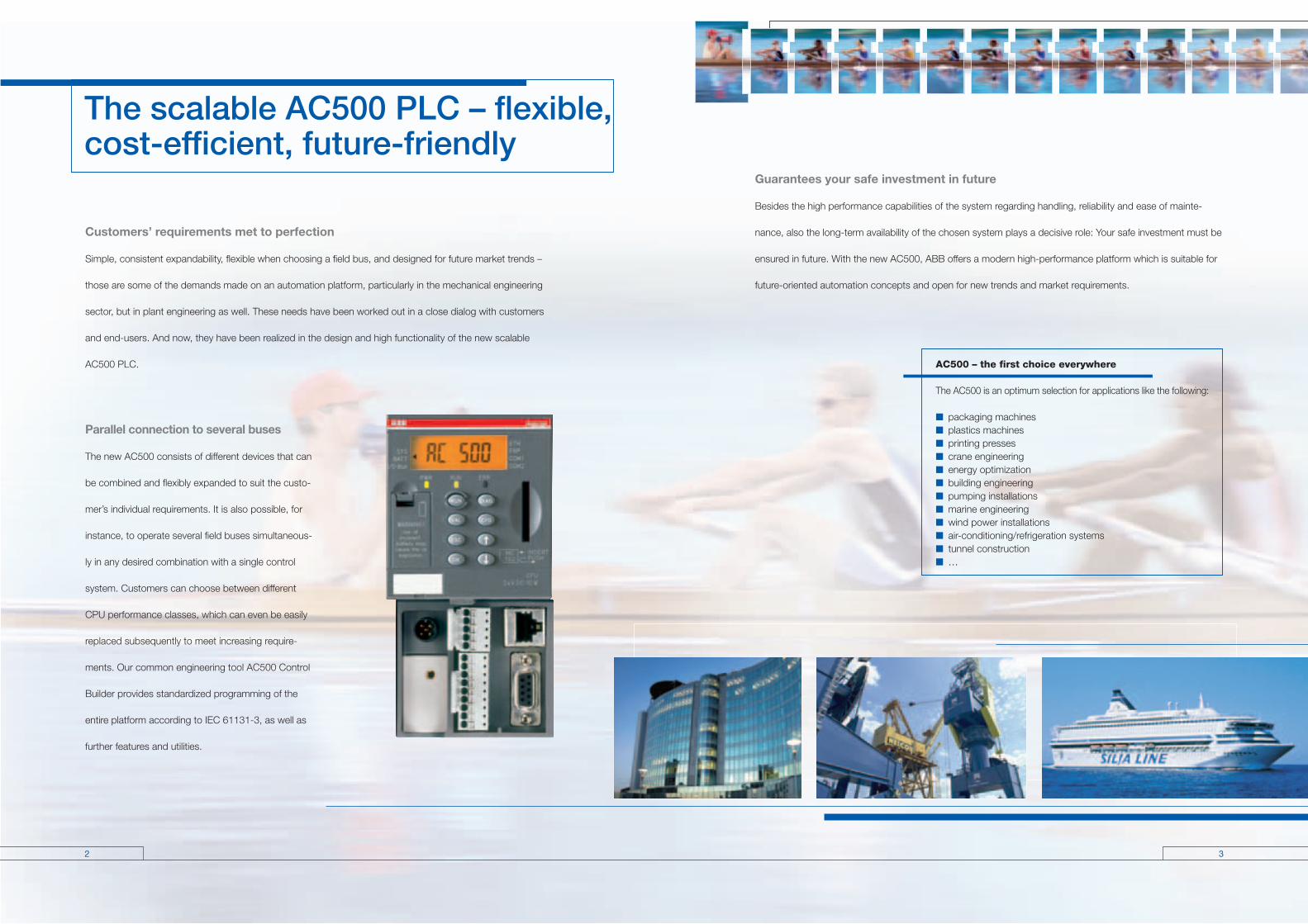
The scalable AC500 PLC – flexible, cost-efficient, future-friendly
Customers’ requirements met to perfection
Simple, consistent expandability, flexible when choosing a field bus, and designed for future market trends –
those are some of the demands made on an automation platform, particularly in the mechanical engineering
sector, but in plant engineering as well. These needs have been worked out in a close dialog with customers
and end-users. And now, they have been realized in the design and high functionality of the new scalable
AC500 PLC.
Parallel connection to several buses
The new AC500 consists of different devices that can
be combined and flexibly expanded to suit the custo-
mer’s individual requirements. It is also possible, for
instance, to operate several field buses simultaneous-
ly in any desired combination with a single control
system. Customers can choose between different
CPU performance classes, which can even be easily
replaced subsequently to meet increasing require-
ments. Our common engineering tool AC500 Control
Builder provides standardized programming of the
entire platform according to IEC 61131-3, as well as
further features and utilities.
Guarantees your safe investment in future
Besides the high performance capabilities of the system regarding handling, reliability and ease of mainte-
nance, also the long-term availability of the chosen system plays a decisive role: Your safe investment must be
ensured in future. With the new AC500, ABB offers a modern high-performance platform which is suitable for
future-oriented automation concepts and open for new trends and market requirements.
AC500 – the first choice everywhere
The AC500 is an optimum selection for applications like the following:
■ packaging machines■ plastics machines ■ printing presses■ crane engineering ■ energy optimization■ building engineering ■ pumping installations ■ marine engineering■ wind power installations■ air-conditioning/refrigeration systems ■ tunnel construction■ …

4 5
Complete product portfolio
ABB offers a complete range of low-voltage devices from one source: PLC,
devices for switching and protection, such as soft starters, contactors, and
circuit-breakers, up to standard sensors. Many of these ABB components have
already been integrated into the innovative system concept involved. Examples
here include the UMC22-FBP Universal Motor Controller for effective motor
protection and particularly user-friendly motor control, the interactive circuit-
breakers Tmax T4, T5, the PSS soft starter and the wireless proximity switch.
With the AC500, the FBP product range has been extended by field-bus-neutral
I/O modules and a CPU which can also be used as a field bus slave via the FBP.
Flexible choice of the field bus
Flexibility in the choice of a field bus without needing
to replace any field devices: That’s the basic idea
behind the field bus plug (FBP). Thanks to this intelli-
gent plug connector, field devices „become“ field-
bus-neutral. Thus, changing the field bus (often due
to end-user’s wishes), only requires the replacement
of the plug connector itself – the field devices and
terminal wiring can be retained.
The FBP is the link to a communicative series of
switching and automation components, which can
thus be combined with standard field bus systems
in the easiest way.
Bus-neutral field devices:
Everything you need forswitching and control
Circuit-breaker Universal Motor controller Motor Starter S500 remote I/Os AC500 Slave Wireless Proximity Switches
Soft Starters

6 7
2
1
31
5
4
67
Clear advantages thanks to clear structures
Flexibility as program
Thanks to its scalability, the AC500 PLC can be adapted to the most different automation tasks: The devices concerned can
be used and combined in a flexible way. The number of different parts to be kept in stock is correspondingly minimized.
The AC500’s system architecture
The CPUs
are available in the performance classes PM571,
PM581 and PM591, can all be programmed in five
different languages, and provide an LCD display, an
operator keypad, an SD card slot, and two inte-
grated serial interfaces. The CPUs can be simply
plugged onto the CPU terminal base. Optionally,
they are also available with integrated Ethernet or
ARCNET.
The communication modules
For connection to standard field bus systems and
integration into existing networks. Up to four com-
munication modules in any desired combination are
allowed at one CPU, resulting in a high degree of
communication.
The CPU terminal base
Available in three different versions, enables easy
plugging of the CPU and one, two or four communi-
cation modules.
The I/O modules
Digital and analog in different versions.
Can be simply plugged onto the terminal units
– for local expansion of the CPU (max. seven modu-
les) and decentralized expansion via the FBP inter-
face. Flexible use thanks to configurable channels.
The terminal units
Multi-purpose usage for both digital and analog I/Os,
for 1, 2 and 3-wire designs. Enable simple prewiring
without electronics. For 24 V DC and 230 V AC,
optionally for spring or screw-type terminals.
The FBP interface module
With embedded digital I/Os and a field-bus-neutral
interface for connecting the chosen FBP connec-
tor. For decentralized expansion by up to seven I/O
modules.
The SD card
Optional for data logging, downloading and uploa-
ding the user program without a PC or a firmware
update for all devices (CPU, couplers or I/O modu-
les).
1 Back-lighted LCD display and keypad
2 SD card slot
3 Plug-in communication modules
(1 to max. 4)
4 Optionally with integrated Ethernet
or ARCNET
5 FBP interface (for slave)
6 Two serial interfaces for programming,
ASCII, Modbus or CS31 field bus (master)
7 Expandable by up to seven local
I/O modules

8 9
AC500 grows to meetrequirements
Network
Modem
Control + communication:
Decentralized expansion:
Networked and communicative
Centralized expansion:

10 11
Member of Automation Alliance
Programming
Control Builder AC500
Control Builder AC500 is the engineering tool for all CPU performance classes of the AC500, designed for
standardized IEC 61131-3 programming in five different languages. Other features of this tool are: Configurati-
on of the overall system including field buses and interfaces, extensive diagnostic functions, alarm handling,
integrated visualization and open software interfaces.
Configurators of the communication interfaces
For PROFIBUS DP, CANopen, DeviceNet, Ethernet,
Modbus and CS31.
Open interfaces
DDE and OPC.
Programming
Serial or via Ethernet or ARCNET networks.
Engineering interface
Provides access from the programming system to an
external project database in which the program
source code of one or several automation projects is
managed. Optionally, a version control system, such
as Visual Source Safe, can be used in order to
ensure data consistency of the program code for
several different users and projects.
• Comprehensive libraries.
• Windows 32-bit standard.
• Operating systems Windows NT, 2000 and XP.
Offline simulation
IEC 61131-3 commands can be simulated without a
PLC being connected, including the relevant mal-
functions. After the program test, the application can
be downloaded to the control system.
Sampling trace
Timing diagrams for process variables and storage of
data in a ring buffer with event trigger.
Recipe management and watch lists
Values of selected variables are displayed. Pre-defined
values can be assigned to variables which can then be
downloaded to the control system all at once (“Write
recipe”). Ongoing values from the control system can also
be pre-assigned for reading into the Watch and Recipe
Manager, and stored in memory there (“Read recipe).
These functions are also helpful, for example, for setting
and entering control parameters.
Visualization
Includes color change, moving elements, bitmaps, text
display, allows input of setpoint values and display of
process variables read from the PLC, dynamic bar
diagrams, alarm and event management, function keys
and ActiveX elements.
Programming in conformity with IEC 61131-3
Besides the suitable hardware, a high-performance,
user-friendly and convenient engineering tool is
indispensable for simple planning, programming,
testing and commissioning of an automation applica-
tion. AC500 Control Builder provides the following
functionalities:
■ Five standardized programming languages:
Function Block Diagram (FBD), Instruction List (IL),
Ladder Diagram (LD), Structured Text (ST), Sequen-
tial Function Chart (SFC)
■ Free graphical function chart (CFC)
■ Debugging functions for the program test:
• Single step
• Single cycle
• Breakpoint

12 13
CP500 – the operator interfaces
Obvious man-machine communication
The AC500 offers as well an extensive range of products for communication between operator and machine.
There are many different displays to choose from, which satisfy application-specific demands regarding
required operator actions and information density. Whether it’s a simple device for displaying text, a graphic-
capability device or a touch-panel with color display, the entire range of control terminals meets the require-
ments for maximized transparency and efficiency for the automation task.
Simple handling
Users can communicate with the AC500’s CPUs via the
various operator panels, read and write access on
device data is possible.
Configuration is quick and easy to perform, using the
same software for all devices. Commands and program-
ming languages are identical for all devices. With regard
to frequently harsh conditions at the place of installation,
all operator panels fulfill IP65 protection at the front.
Operator panels and automation devices are linked
either simply via serial interfaces, or in case of complex
applications via Ethernet, Modbus or PROFIBUS DP.
Functionalities in line with demand
Depending on the used device type, the operator panels
feature the following functions:
■ real-time clock
■ alarm management in several different groups
■ trend curves and datalogger
■ recipe management
■ report printouts
■ password protection
■ Flash memory up to 1600 kB
14 15
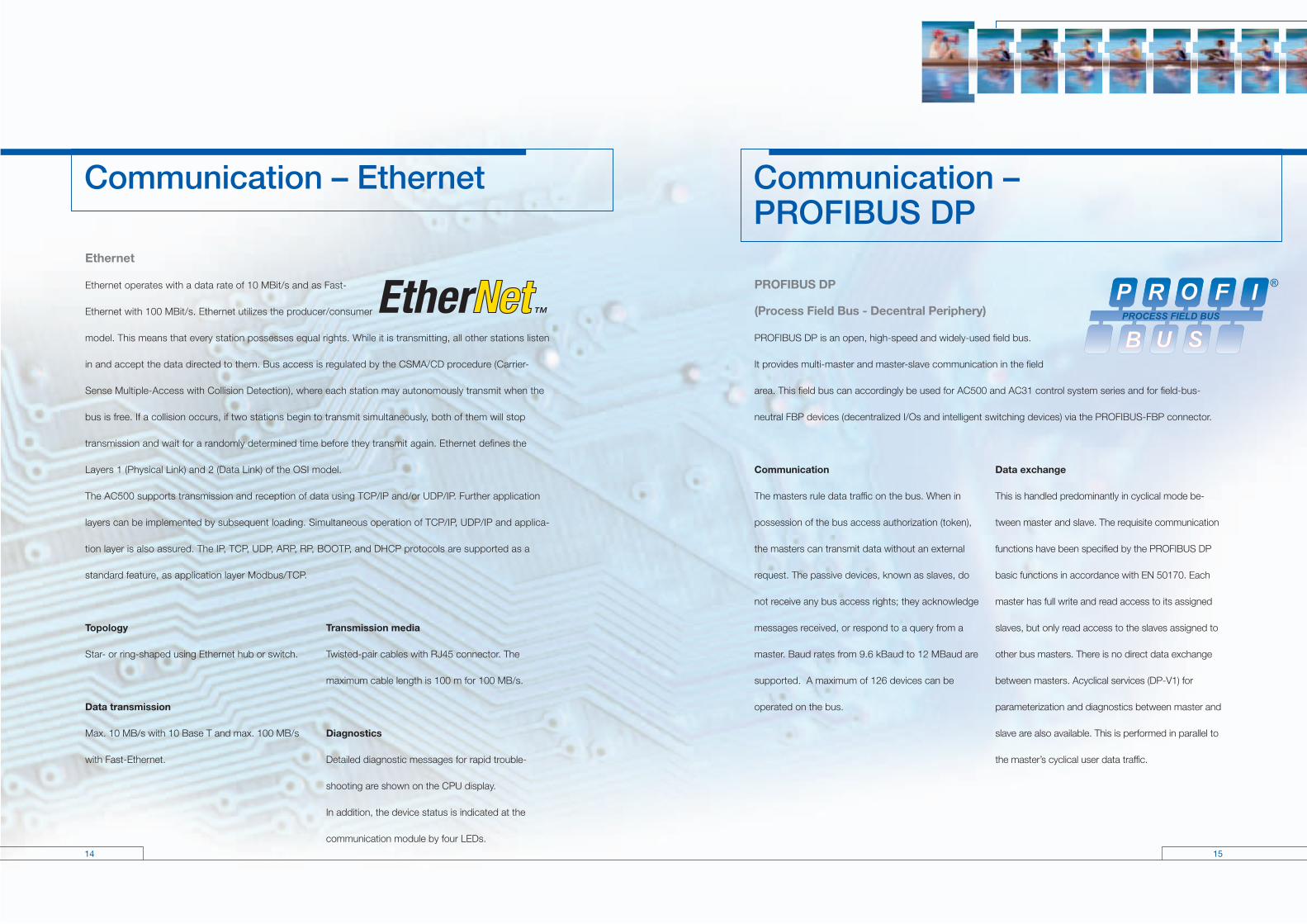
Ethernet
Ethernet operates with a data rate of 10 MBit/s and as Fast-
Ethernet with 100 MBit/s. Ethernet utilizes the producer/consumer
model. This means that every station possesses equal rights. While it is transmitting, all other stations listen
in and accept the data directed to them. Bus access is regulated by the CSMA/CD procedure (Carrier-
Sense Multiple-Access with Collision Detection), where each station may autonomously transmit when the
bus is free. If a collision occurs, if two stations begin to transmit simultaneously, both of them will stop
transmission and wait for a randomly determined time before they transmit again. Ethernet defines the
Layers 1 (Physical Link) and 2 (Data Link) of the OSI model.
The AC500 supports transmission and reception of data using TCP/IP and/or UDP/IP. Further application
layers can be implemented by subsequent loading. Simultaneous operation of TCP/IP, UDP/IP and applica-
tion layer is also assured. The IP, TCP, UDP, ARP, RP, BOOTP, and DHCP protocols are supported as a
standard feature, as application layer Modbus/TCP.
Topology
Star- or ring-shaped using Ethernet hub or switch.
Data transmission
Max. 10 MB/s with 10 Base T and max. 100 MB/s
with Fast-Ethernet.
Transmission media
Twisted-pair cables with RJ45 connector. The
maximum cable length is 100 m for 100 MB/s.
Diagnostics
Detailed diagnostic messages for rapid trouble-
shooting are shown on the CPU display.
In addition, the device status is indicated at the
communication module by four LEDs.
Communication – Ethernet Communication – PROFIBUS DP
PROFIBUS DP
(Process Field Bus - Decentral Periphery)
PROFIBUS DP is an open, high-speed and widely-used field bus.
It provides multi-master and master-slave communication in the field
area. This field bus can accordingly be used for AC500 and AC31 control system series and for field-bus-
neutral FBP devices (decentralized I/Os and intelligent switching devices) via the PROFIBUS-FBP connector.
Communication
The masters rule data traffic on the bus. When in
possession of the bus access authorization (token),
the masters can transmit data without an external
request. The passive devices, known as slaves, do
not receive any bus access rights; they acknowledge
messages received, or respond to a query from a
master. Baud rates from 9.6 kBaud to 12 MBaud are
supported. A maximum of 126 devices can be
operated on the bus.
Data exchange
This is handled predominantly in cyclical mode be-
tween master and slave. The requisite communication
functions have been specified by the PROFIBUS DP
basic functions in accordance with EN 50170. Each
master has full write and read access to its assigned
slaves, but only read access to the slaves assigned to
other bus masters. There is no direct data exchange
between masters. Acyclical services (DP-V1) for
parameterization and diagnostics between master and
slave are also available. This is performed in parallel to
the master’s cyclical user data traffic.
16 17
Diagnostics
Detailed diagnostic messages for rapid
trouble-shooting are shown on the
CPU display. In addition, the device
status is indicated at the communica-
tion module by four LEDs.
Communication – Modbus®
Modbus® RTU (developed by Modicon in 1979)
Modbus® RTU is an open master/slave protocol, and can be easily implemented on serial interfaces.
Numerous automation systems have Modbus® RTU interfaces as standard or optional features, and are thus
easily able to communicate with the AC500 via its integrated COM1 and COM2 interfaces (RS232 or RS485).
The Modbus® is used not only in industrial applications, but also in building installations, in energy optimization
systems, for long-distance data transmission and for linking up operator panels.
Communication
By polling, i.e. the master transmits a request to the
slave and then receives the response. Both interfaces
COM1 and COM2 can operate simultaneously as
Modbus interfaces. The Modbus operating mode of
an interface is set using the engineering tool.
Topology
Point-to-point via RS232 or multi-point via RS485.
With RS232, a maximum of one master and one
slave is possible, while with RS485 one master and a
maximum of 31 slaves can be operated. The maxi-
mum cable length is 15 m with RS232 and 1.2 km
with RS485.
Data transfer
Max. 187.5 kB/s. Each telegram has a 16-bit CRC
appended. The telegrams permit process data (input/
output data) to be written and read, either individually
or in groups. The data are packed in the RTU format.
Transmission media
May vary. One widely used option is the RS485 bus
physics, a twisted-pair, shielded cable with termina-
tors.
Diagnostics
Detailed diagnostic messages for rapid trouble-shoot-
ing are shown on the CPU display.
PROFIBUS DP – the functionality at a glance
■ Max. 126 subscribers via amplifier and max. 32 subscribers (master/slaves)
per bus segment
■ Data transmission rate from max. 12 MBit/s with a cable length of 100 m,
up to 93.75 kBit/s with 1200 m
■ Multi-master or master/slave communication. Bus access of the masters
using token
■ Connection of the master CPU and the associated communication module
via a 9-pole SUB-D plug connector. Connection of slaves (CPU, I/Os and
intelligent switching devices) via FieldBusPlug
■ The system cable is a shielded twisted-pair line or a fiber-optic cable;
transmission standard EIA RS485

18 19
CANopen
The bus operates on the master/slave principle with
one master and up to 127 slaves. A shielded twisted-
pair cable is used, according to ISO 11898. Cable
lengths and transmission rates: from max. 40 m at
1 MBit/s to 1000 m at 20 kBit/s.
DeviceNet
The bus operates on the multi-master and/or the
master/slave principle, with up to 64 bus subscribers.
Two types of shielded twisted-pair cables are used:
trunk cable for the main line and drop cable for the
branch line.
Diagnostics
Detailed diagnostic messages for rapid trouble-
shooting are shown on the CPU display. In addition,
the device status is indicated at the communication
module by four LEDs.
Communication – CANopen and DeviceNet
CANopen (Controller Area Network) and
DeviceNet
The CAN protocol was originally developed for the European auto-
motive industry, so as to replace expensive cabling by an affordable
network cable. Today, it is also used in the field of automation for
transmitting process data between control systems, decentralized
I/O modules, drives, valves, etc. CAN features a high level of transmission security, since large portions of the
monitoring mechanisms have been implemented directly in the CAN chip. DeviceNet and CANopen utilize the
physical structure and the data transport mechanisms of CAN (Controller Area Network). The difference lies in
the transmission protocols. DeviceNet and CANopen can be used correspondingly for the AC500 and AC31
controller series and for field-bus-neutral FBP devices (decentralized I/Os and intelligent switching devices), via
the CANopen-FBP plug connector.
Data transmission
Two types of message have been defined: I/O data
transfer and direct link. I/O data transfer is used for
time-critical process data, while the direct link can
be, for example, used for diagnostic messages.
Bus access for subscribers
The connection ID with the lower address has higher
priority on the bus. Data is transmitted by the source,
while the sinks (i.e. receivers of the data) have like-
wise been specified during the configuration phase.
Transmission rate 125 kBit/s 250 kBit/s 500 kBit/s
Max. cable length of trunk line 500 m 250 m 100 mTrunk cable (1610 ft) (820 ft) (328 ft)
Max. cable length of trunk line 100 m 100 m 100 mDrop cable (328 ft) (328 ft) (328 ft)
Max. cable length per branch line 6 m 6 m 6 mTrunk cable/Drop cable (20 ft) (20 ft) (20 ft)
Max. cable length total branch line 156 m 78 m 39 mTrunk cable/Drop cable (512 ft) (256 ft) (128 ft)
20 21
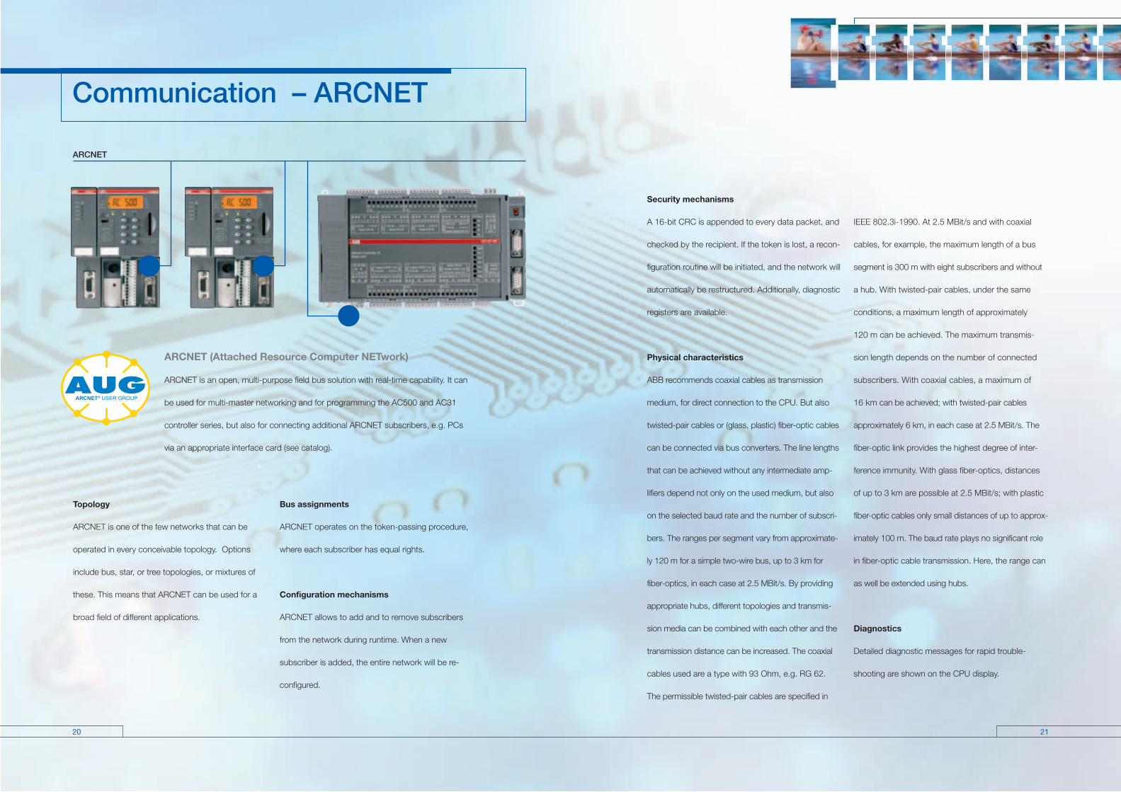
ARCNET
ARCNET (Attached Resource Computer NETwork)
ARCNET is an open, multi-purpose field bus solution with real-time capability. It can
be used for multi-master networking and for programming the AC500 and AC31
controller series, but also for connecting additional ARCNET subscribers, e.g. PCs
via an appropriate interface card (see catalog).
Topology
ARCNET is one of the few networks that can be
operated in every conceivable topology. Options
include bus, star, or tree topologies, or mixtures of
these. This means that ARCNET can be used for a
broad field of different applications.
Bus assignments
ARCNET operates on the token-passing procedure,
where each subscriber has equal rights.
Configuration mechanisms
ARCNET allows to add and to remove subscribers
from the network during runtime. When a new
subscriber is added, the entire network will be re-
configured.
Security mechanisms
A 16-bit CRC is appended to every data packet, and
checked by the recipient. If the token is lost, a recon-
figuration routine will be initiated, and the network will
automatically be restructured. Additionally, diagnostic
registers are available.
Physical characteristics
ABB recommends coaxial cables as transmission
medium, for direct connection to the CPU. But also
twisted-pair cables or (glass, plastic) fiber-optic cables
can be connected via bus converters. The line lengths
that can be achieved without any intermediate amp-
lifiers depend not only on the used medium, but also
on the selected baud rate and the number of subscri-
bers. The ranges per segment vary from approximate-
ly 120 m for a simple two-wire bus, up to 3 km for
fiber-optics, in each case at 2.5 MBit/s. By providing
appropriate hubs, different topologies and transmis-
sion media can be combined with each other and the
transmission distance can be increased. The coaxial
cables used are a type with 93 Ohm, e.g. RG 62.
The permissible twisted-pair cables are specified in
IEEE 802.3i-1990. At 2.5 MBit/s and with coaxial
cables, for example, the maximum length of a bus
segment is 300 m with eight subscribers and without
a hub. With twisted-pair cables, under the same
conditions, a maximum length of approximately
120 m can be achieved. The maximum transmis -
sion length depends on the number of connected
subscribers. With coaxial cables, a maximum of
16 km can be achieved; with twisted-pair cables
approximately 6 km, in each case at 2.5 MBit/s. The
fiber-optic link provides the highest degree of inter-
ference immunity. With glass fiber-optics, distances
of up to 3 km are possible at 2.5 MBit/s; with plastic
fiber-optic cables only small distances of up to approx-
imately 100 m. The baud rate plays no significant role
in fiber-optic cable transmission. Here, the range can
as well be extended using hubs.
Diagnostics
Detailed diagnostic messages for rapid trouble-
shooting are shown on the CPU display.
Communication – ARCNET

22 23
CS31
ARCNET – the functionality at a glance
■ Guaranteed collision-free data transmission, guaranteed response times and real-time capability thanks to
token-passing
■ Large network dimensions: network length 300 m, with amplifier max. 16 km
■ Secure, thanks to checksums in the data packet and handshake protocol between transmitter and receiver
■ Variable network structure: bus, tree and star topologies are possible, plus any desired mixtures of them
■ Variable networking media, coaxial cables, twisted-pair cables and fiber-optic cables can be mixed
■ Automatic subscriber log-on and log-off; the network automatically incorporates new stations in the ring and
cancels them as well
■ Master-master access: the subscriber that holds the token is the master. With up to 255 masters at the same
network
■ Data transmission rate of max. 2.5 MBit/s
■ ARCNET is configured and programmed using the AC500 Control Builder engineering tool
CS31 (Communication Serial Field Bus, developed by ABB in 1989) for continuity and migration
CS31 is a proprietary master/slave field bus. It is characterized by simple handling, easy configuration, and inexpensive
installation. The COM1 interface of the AC500 can be configured as a CS31 field bus master.
Communication
Is handled using polling, i.e. the master sends a
request to the slave and then receives the response.
The CS31 operating mode of COM1 is set using the
engineering tool.
Data transmission
Is performed at 187.5 kB/s. Each telegram has an 8-bit
CRC appended. The telegrams enable process data
(input/output data) to be written and read.
Transmission medium
Primarily a twisted-pair, shielded cable with termina-
tors. Other transmission media: fiber-optic cables via
a converter (glass fibers max. 3 km, plastic max.
100 m), contact lines, slip rings (bus length max.
50 m) and data photocells.
Communication – CS31
Topology
Multi-point line, RS485, approved without branch
lines. A system consists of one master and up to 31
slaves. The maximum cable length is 500 m, or 2 km
with an amplifier. Slaves are primarily decentralized
input/output modules with integrated CS31 bus
connection.
Diagnostics
Detailed diagnostic messages for rapid trouble-
shooting are shown on the CPU display.

24 25
Scalable automation system AC500
DetailsType: PM571 PM571-ETH PM581 PM581-ETH PM581-ARC PM591 PM591-ETH PM591-ARC
Supply voltage 24 V DC 24 V DC 24 V DC 24 V DC
Total memorySDRAM (kByte) 4026 8192 32768Flash (kByte) 1024 2048 8192SRAM (kByte) 128 512 2048
Program memory Flash EPROM und RAM [kByte] 64 256 4096
Data memory integrated [kByte] 21, incl. 1 KB RETAIN 288, incl. 32 KB RETAIN 3072, incl. 512 KB RETAIN
Plug-in memory card [SD card] 128 MB 128 MB 128 MB
Cycle time for 1000 instructions in msBinary 0.3 0.15 0.05Word 0.3 0.15 0.05Floating-point 6 3 0.5
Number of centralized inputs/outputs max. Binary inputs 224 224 224Binary outputs 168 168 168Analog inputs 112 112 112Analog outputs 112 112 112
Number of decentralized inputs/outputs max. depends on used field bus
Data buffering Battery Battery Battery
Real-time clock x x x
Program execution Cyclical x x x Time-controlled x x x Multitasking x x x
User program protection by password x x x
Interfaces integrated
COM1:RS232/RS485 configurable x x xConnection Terminal block Terminal block Terminal block Prog., Modbus, ASCII, CS31 x x x
COM2:RS232/RS485 configurable x x xConnection SUB-D SUB-D SUB-DProg., Modbus, ASCII x x x
Ethernet coupler integrated x x xConnection Ethernet RJ45 RJ45 RJ45
ARCNET coupler integrated x xConnection ARCNET Coax Coax
Display and 8 function keys x x x RUN/STOP RUN/STOP RUN/STOPFunction Status, diagnostics Status, diagnostics Status, diagnostics
Timers unlimited unlimited unlimited
Counters unlimited unlimited unlimited
Function Block Diagram (FBD) x x xInstruction List (IL) x x xLadder Diagram (LD) x x xStructured Text (ST) x x xSequential Function Chart (SFC) x x xContinuous Function Chart (CFC) x x x
Approvals CE, GL, DNV, BV, RINA, LRS, CSA, UL
Analog I/O modules AX522 Supply voltage 24 V DC Number of analog inputs 8 Input ranges 0 ... 10 V, ±10 V 0/4 ... 20 mA Pt100 -50 ... +400 °C 2/3-wire Pt1000 -50 ... +400 °C 2/3-wire Ni1000 -50 ... +150 °C 2/3-wire Number of analog outputs 8 Output ranges ±10 V 0/4 ... 20 mA (max. 4 current outputs) Short-circuit/overload protection x Resolution 12 bit + sign Potential isolation per module
Operating state indicators Status indication for each input/output LED yellowSupply voltage LED greenFault indicator LED red
Binary I/O modules
DI524 DC532 DX522 DX531
Supply voltage 24 V DC 24 V DC 24 V DC 24 V DC
Number of binary inputs and outputs DI/DO/DC (configurable channels) 32/- /- 16 /-/16 8/ 8/- 8/4/-
Input voltage 24 V DC 24 V DC 24 V DC 115 ... 230 V AC
Input time-delay ms configurable configurable configurable typ. 20 0.1/1/8/32 0.1/1/8/32 0.1/1/8/32
Inputs as fast counters* 2 2 2
Counting frequency kHz max. 50 50 50
Outputs Transistor 24 V DC, 0,5 A xRelay 230 V AC, 3 A x1) x1)
Total current per module 8 A
Short-circuit/overload protection yes
Potential isolation per module per module per module per module
Operating state indicators Status indication for each input/output LED yellow LED yellow LED yellow LED yellow Supply voltage LED green LED green LED green LED green Fault indicator LED red LED red LED red LED red
Notes 1) changeover contacts *when local I/O modules

26 2726 27
Interface modules DC505-FBP DC551-CS31
Field buses PROFIBUS DP*) CS31 CANopen*)
DeviceNet*)
Modbus RTU*)
Interface via FBP integrated
Supply voltage 24 V DC 24 V DC
Number of binary inputs and outputs DI/DO/DC (configurable channels) 8/-/8 8/- /16
Input voltage 24 V DC 24 V DC
Input time-relay configurable configurable 0.1/ 1/8/ 32 ms 0.1/ 1/8/ 32 ms
Outputs transistor Output voltage/current 24 V DC/ 0,5 A 24 V DC/0,5 A
Total current per module 4 A 8 A
Short-circuit/overload protection yes yes
Operating state indicators Supply voltage FBP LED green LED greenFBP communication LED greenCS31 communication LED greenSumcheck error LED red LED redI/O bus communication LED green LED greenStatus indication for each input/output LED yellow LED yellowSupply voltage I/Os LED green LED greenFault indicator I/Os LED red LED red
Potential isolation from the bus from the bus per module per module
Operating and environmental conditions
Voltages according to EN 61131-2
24 V DC Process and supply voltage 24 V DC (-15%, +20% without residual ripple) Absolute limits 19,2 V ... 30 V incl. residual ripple Residual ripple < 5% Polarity reversal protection 10 s120 V AC Supply voltage 120 V AC (-15%, +10%) Frequency 47 Hz ... 62,4 Hz/50 ... 60 Hz (-6%, +4%)230 V AC Supply voltage 230 V AC (-15 %, +10%) Frequency 47 Hz ... 62,4 Hz/50 ... 60 Hz (-6%, +4 %)120–240 V AC Wide voltage input Voltage 102 V ... 264 V/120 V ... 240 V (-15%, +10%) Frequency 47 Hz ... 62,4 Hz/50 ... 60 Hz (-6%, +4%)
*) depending on the FBP; the module itself is field-bus-neutral
Power failure bridging time according to EN 61131-2 DC-supply Failure < 10 ms, time between 2 failures > 1 s AC-supply Failure < 0,5 periods, time between 2 failures > 1 sTemperature Operation 0 °C ... +55 °C Storage -25 °C ... +75 °C Transport -25 °C ... +75 °CHumidity 50 ... 95%, without condensation Air pressure Operation > 800 hPa /< 2000 m Storage > 660 hPa / < 3500 m
Creepage distances and clearances
The creepage and clearance distances correspond to Overvoltage Category II, Pollution Severity 2
Electromagnetic compatibility Interference immunity
against electrostatic discharge (ESD) acc. to EN 61000-4-2, Zone B, Criteria B Interference voltage with air discharge 8 kVInterference voltage with contact discharge 6 kV
Interference immunity
against radiated interference (CW radiated) acc. to EN 61000-4-3, Zone B, Criteria A Test field strength 10 V/m
Interference immunity
against transient interference voltages (burst) acc. to EN 61000-4-4, Zone B, Criteria B
Interference immunity
against conduction-bound interferences (CW conducted) acc. to EN 61000-4-6, Zone B, Criteria A Test voltage 3V Zone B
Impulse voltage acc. to EN 61000-4-5, Zone B, Criteria B
Emitted interference acc. to EN 55011, Group 1, Class A Mechanical data Connection type/Terminals Mounting horizontal Degree of protection IP 20Housing acc. to UL 94 Vibration-resistance all three axes 2 Hz ... 15 Hz, continuous 3,5 mm 15 Hz ... 150 Hz, continuous 4 gVibration-resistance with SD card plugged in 15 Hz ... 150 Hz, continuous 1 gShock-resistance all three axes 15 g, 11 ms, semi-sinusoidal Device mounting DIN top-hat rail acc. to DIN EN 50022 35 mm, overall height 7.5 mm or 15 mm Screw mounting Screws with 4 mm diameter Torque
Scalable automation system AC500
System data

28 29
CP501 CP502 CP503 CP511 CP512 CP513 CP551 CP552 CP554 CP555
Ident. No. 1SBP 260170 R0101 1SBP 260171 R0101 1SBP 260172 R0101 1SBP 260173 R0101 1SBP 260174 R0101 1SBP 260175 R0101 1SBP 260176 R0101 1SBP 260177 R0101 1SBP 260178 R0101 1SBP 260179 R0101
Display type STN LCDwith backlight
STN LCDwith backlight
STN LCDwith backlight
STN LCDwith backlight
B/W STN LCDwith backlight
TFT 256 Color LCDwith backlight
Touch B/W STNwith backlight
16 grey levels Touch LCDwith backlight
TFT 256 Color touch LCD TFT 256 Color touch LCD
Representation Text Text Text Graphic and text Graphic and text Graphic and text Graphic and text Graphic and text Graphic and text Graphic and text
Display size 2 lines x 16 characters 2 lines x 20 characters 4 lines x 20 characters 240 x 64 pixels (5.2") 240 x 128 pixels (5.3") 320 x 240 pixels (5.7") 320 x 240 pixels (5.7") 320 x 240 pixels (5.7") 320 x 240 pixels (5.7") 640 x 480 pixels (10.4")
Display area W x H (mm)
55.7 x 11.0 73.5 x 11.5 70.4 x 20.8 127.2 x 33.9 120.0 x 64.0115.2 x 86.4 78.0 x 58.5 115.2 x 86.4 115.2 x 86.4 211.2 x 158.4
Text height (mm) 5 5 5 variable variable variable variable variable variable variable
LEDs 5 (2 colors) 16 (2 colors) 16 (2 colors) 16 (2 colours)
Function keys 4 3 5 816 (8 with
labeling strip)16 (8 with
labeling strip)
Web functions ● ● ● ● ● ● ●
Buzzer ● ● ● ● ● ● ●
Alarm management 1 group 4 groups 4 groups 16 groups 4 groups 5 groups 5 groups 11 groups
Time channel ● ● ● ● ● ● ● ● ●
Real-time clock ● ● ● ● ● ● ● ● ●
Trend curves real-time developing of values developing of values developing of values developing of values developing of values developing of values
Datalogger ● ● ● ● ●
Recipe management ● ● ● ● ● ● ● ● ●
Report printing ● ● ● ● ● ● ● ● ●
Password protection 8 levels 8 levels 8 levels 8 levels 8 levels 8 levels 8 levels 8 levels 8 levels
Multilanguagesupport
● ● ● ●● ● ● ● ●
Applicationmemory
16 kB Flash 64 kB Flash 64 kB Flash 400 kB Flash 400 kB Flash 400 kB Flash 400 kB Flash 400 kB Flash 400 kB Flash 1600 kB Flash
Power supply 24 V DC 24 V DC 24 V DC 24 V DC 24 V DC 24 V DC 24 V DC 24 V DC 24 V DC 24 V DC
Current consumption
200 mA 150 mA 150 mA 450 mA 450 mA 550 mA 150 mA 400 mA 450 mA 1 A
Ambienttemperature
0 – 50 °C 0 – 50 °C 0 – 50 °C 0 – 50 °C 0 – 50 °C0 – 50 °C 0 – 50 °C 0 – 50 °C 0 – 50 °C 0 – 50 °C
Communicationinterfaces
RS232 or RS422RS232, RS422
RS485 (of which 2 at the same time)
RS232, RS422RS485 (of which
2 at the same time)RS232, RS422 RS232, RS422 RS232, RS422
RS232, RS422RS485, Ethernet
(of which 2 at the same time)
RS232, RS422RS485
(of which 2 at the same time)
RS232, RS422RS485
(of which 2 at the same time)RS232, RS422
Expansion slots – – - 1 1 2 - 1 1 2
Degree of protectionfront cover
IP65 IP65 IP65 IP65 IP65 IP65 IP65 IP65 IP65 IP65
DimensionsW x H x D (mm)
104 x 69 x 38 142 x 90 x 47,5 147 x 163,5 x 38 211 x 198 x 69 214 x 232 x 87 276 x 198 x 89 142 x 90 x 47,5 200 x 150 x 69 200 x 150 x 69 290 x 250 x 105
Weight (kg) 0.2 0.5 0.7 1.5 1.4 1.7 0,6 1.5 1.5 3.3
Operating and displayingOperator panels CP500 – Overview

30 31
The AC500 CPU´s■ 2 serial interfaces integrated, RS232/RS485 configurable
■ Display and 8 function keys for diagnosis and status
■ Centrally expandable with up to 7 expansion modules
■ Up to 4 external communication modules simultaneously and in
any desired combination
■ Optional: SD card for data storage and program backup Communication module Profibus DP Profibus DP Master up to 12 MBit/s A maximum of 4 CM572-DP modules can be operated simultaneously at one CPU No external power supply required
Type Interface Ordering Number Weight 1 pc./kg
CM572-DP Sub-D socket 1SAP 170 200 R0001
Communication module DeviceNet
Type Interface Connector Ordering Number Weight 1 pc./kg
CM575-DN Plug-in Spring-type available 2006 terminal block terminals
Communication module CANopen
Type Interface Connection Ordering Number Weight 1 pc./kg
CM578-CN Plug-in Spring-type available 2006 terminal block terminals
Terminal base For mounting and connecting the CPUs and communication modules 1 to 4 plug-in communication modules Connection for communication coupler integrated in the CPU I/O interface for direct connection of up to 7 expansion modules Field-bus-neutral FieldBusPlug-Slave interface Connection COM1: 9-pole with pluggable terminal block Connection COM2: 9-pole SUB-D (socket)
Type No. of Connection for Ordering Number Weight coupler slots coupler integrated 1 pc./kg in CPU
TB511-ETH 1 Ethernet RJ45 1SAP 111 100 R0170 TB521-ETH 2 Ethernet RJ45 1SAP 112 100 R0170 0.215 TB541-ETH 4 Ethernet RJ45 1SAP 114 100 R0170 TB521-ARCNET 2 ARCNET COAX available 2006
The AC500, PM571 basic units
Type Program- Cycle time ms Integrated Ordering Number Weight memory 1000 instruct. coupler 1 pc./kg Bit/Word/Float
PM571 64 KB 0.3/0.3/6 - 1SAP 130 100 R0100 0.135 PM571-ETH 64 KB 0.3/0.3/6 Ethernet 1SAP 130 100 R0170 0.150
The AC500, PM581 basic units
Type Program- Cycle time ms Integrated Ordering Number Weight memory 1000 instruct. coupler 1 pc./kg Bit/Word/Float
PM581 256 KB 0.15/0.15 /3 - 1SAP 140 100 R0100 0.135 PM581-ETH 256 KB 0.15/0.15 /3 Ethernet 1SAP 140 100 R0170 0.150 PM581-ARCNET 256 KB 0.15/0.15 /3 ARCNET available 2006 0.160
The AC500, PM591 basic units
Type Program- Cycle time ms Integrated Ordering Number Weight memory 1000 instruct. coupler 1 pc./kg Bit/Word/Float
PM591 4096 KB 0.05/0.05/0.5 - 1SAP 150 100 R0100 0.135PM591-ETH 4096 KB 0.05/0.05/0.5 Ethernet 1SAP 150 100 R0170 0.150PM591-ARCNET 4096 KB 0.05/0.05/0.5 ARCNET available 2006 0.160
Communication Module Ethernet 10/100 MBit/s Full /Half Duplex with auto-sensing 2-Port switch integrated Transport protocols TCP/IP, UDP/IP, Modbus TCP A maximum of 4 CM577-ETH modules can be operated simultaneously at one CPU No external power supply required
Type Protocol Interfaces Ordering Number Weight 1 pc./kg
CM577-ETH TCP/IP, UDP/IP, Modbus TCP 2 x RJ45 1SAP 170 700 R0001
Ordering data
32 33
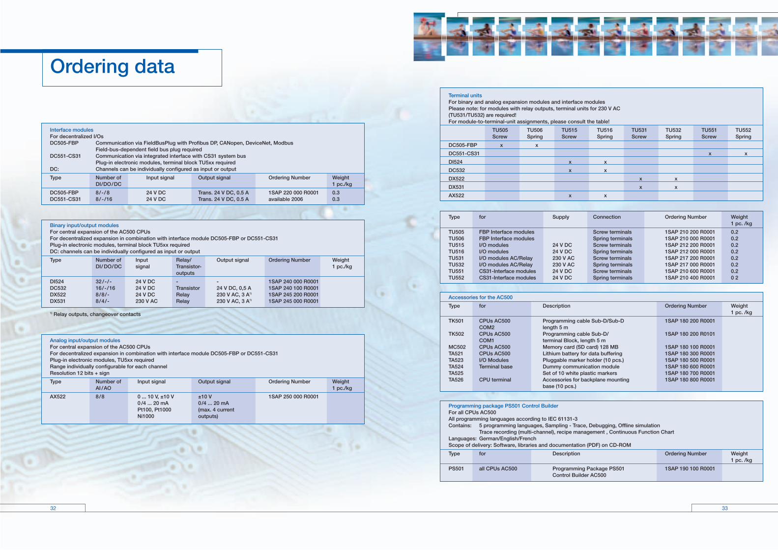
Interface modulesFor decentralized I/Os DC505-FBP Communication via FieldBusPlug with Profibus DP, CANopen, DeviceNet, Modbus Field-bus-dependent field bus plug required DC551-CS31 Communication via integrated interface with CS31 system bus Plug-in electronic modules, terminal block TU5xx required DC: Channels can be individually configured as input or output
Type Number of Input signal Output signal Ordering Number Weight DI/DO/DC 1 pc./kg
DC505-FBP 8/-/ 8 24 V DC Trans. 24 V DC, 0.5 A 1SAP 220 000 R0001 0.3 DC551-CS31 8/ -/16 24 V DC Trans. 24 V DC, 0.5 A available 2006 0.3
Binary input/output modules For central expansion of the AC500 CPUs For decentralized expansion in combination with interface module DC505-FBP or DC551-CS31 Plug-in electronic modules, terminal block TU5xx required DC: channels can be individually configured as input or output
Type Number of Input Relay/ Output signal Ordering Number Weight DI/ DO/DC signal Transistor- 1 pc./kg outputs
DI524 32 /-/- 24 V DC - - 1SAP 240 000 R0001 DC532 16/-/16 24 V DC Transistor 24 V DC, 0,5 A 1SAP 240 100 R0001 DX522 8/8/- 24 V DC Relay 230 V AC, 3 A1) 1SAP 245 200 R0001 DX531 8/4/- 230 V AC Relay 230 V AC, 3 A1) 1SAP 245 000 R0001 1) Relay outputs, changeover contacts
Analog input/output modules For central expansion of the AC500 CPUs For decentralized expansion in combination with interface module DC505-FBP or DC551-CS31 Plug-in electronic modules, TU5xx requiredRange individually configurable for each channel Resolution 12 bits + sign
Type Number of Input signal Output signal Ordering Number Weight AI /AO 1 pc./kg
AX522 8/8 0 ... 10 V, ±10 V ±10 V 1SAP 250 000 R0001 0 /4 ... 20 mA 0/4 ... 20 mA Pt100, Pt1000 (max. 4 current Ni1000 outputs)
Terminal units For binary and analog expansion modules and interface modules Please note: for modules with relay outputs, terminal units for 230 V AC (TU531/TU532) are required! For module-to-terminal-unit assignments, please consult the table!
TU505 TU506 TU515 TU516 TU531 TU532 TU551 TU552 Screw Spring Screw Spring Screw Spring Screw Spring
DC505-FBP x x
DC551-CS31 x x
DI524 x x
DC532 x x
DX522 x x
DX531 x x
AX522 x x
Type for Supply Connection Ordering Number Weight 1 pc. /kg
TU505 FBP Interface modules Screw terminals 1SAP 210 200 R0001 0.2TU506 FBP Interface modules Spring terminals 1SAP 210 000 R0001 0.2 TU515 I/O modules 24 V DC Screw terminals 1SAP 212 200 R0001 0.2 TU516 I/O modules 24 V DC Spring terminals 1SAP 212 000 R0001 0.2 TU531 I/O modules AC/Relay 230 V AC Screw terminals 1SAP 217 200 R0001 0.2 TU532 I/O modules AC/Relay 230 V AC Spring terminals 1SAP 217 000 R0001 0.2 TU551 CS31-Interface modules 24 V DC Screw terminals 1SAP 210 600 R0001 0.2TU552 CS31-Interface modules 24 V DC Spring terminals 1SAP 210 400 R0001 0 2
Accessories for the AC500
Type for Description Ordering Number Weight 1 pc. /kg
TK501 CPUs AC500 Programming cable Sub-D/Sub-D 1SAP 180 200 R0001 COM2 length 5 m TK502 CPUs AC500 Programming cable Sub-D/ 1SAP 180 200 R0101 COM1 terminal Block, length 5 m MC502 CPUs AC500 Memory card (SD card) 128 MB 1SAP 180 100 R0001 TA521 CPUs AC500 Lithium battery for data buffering 1SAP 180 300 R0001 TA523 I/O Modules Pluggable marker holder (10 pcs.) 1SAP 180 500 R0001TA524 Terminal base Dummy communication module 1SAP 180 600 R0001TA525 Set of 10 white plastic markers 1SAP 180 700 R0001TA526 CPU terminal Accessories for backplane mounting 1SAP 180 800 R0001 base (10 pcs.)
Programming package PS501 Control Builder For all CPUs AC500 All programming languages according to IEC 61131-3 Contains: 5 programming languages, Sampling - Trace, Debugging, Offline simulation Trace recording (multi-channel), recipe management , Continuous Function ChartLanguages: German/English/FrenchScope of delivery: Software, libraries and documentation (PDF) on CD-ROM
Type for Description Ordering Number Weight 1 pc. /kg
PS501 all CPUs AC500 Programming Package PS501 1SAP 190 100 R0001 Control Builder AC500
Ordering data
34 35
Lloyd´sRegister OfShipping
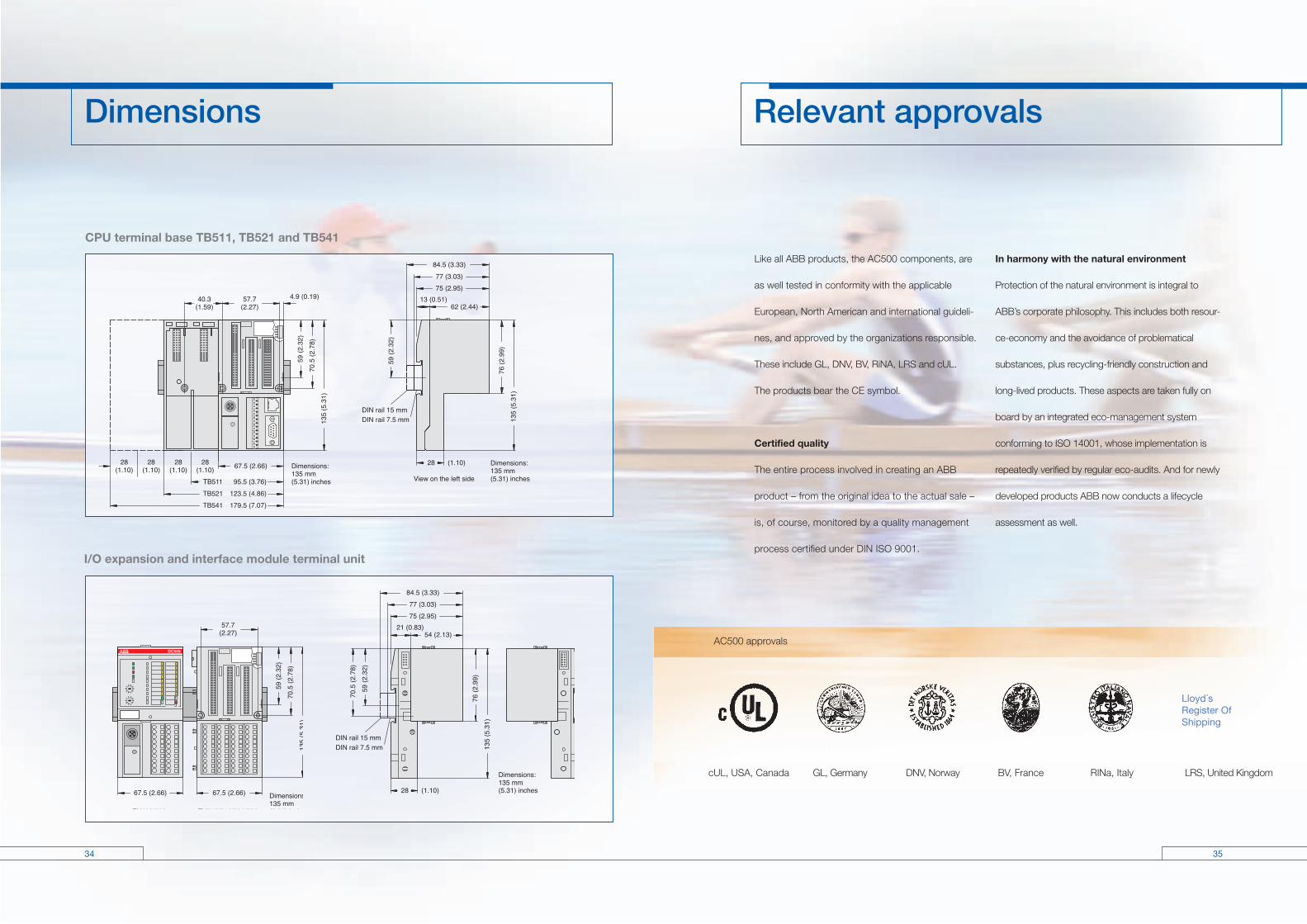
Like all ABB products, the AC500 components, are
as well tested in conformity with the applicable
European, North American and international guideli-
nes, and approved by the organizations responsible.
These include GL, DNV, BV, RiNA, LRS and cUL.
The products bear the CE symbol.
Certified quality
The entire process involved in creating an ABB
product – from the original idea to the actual sale –
is, of course, monitored by a quality management
process certified under DIN ISO 9001.
In harmony with the natural environment
Protection of the natural environment is integral to
ABB’s corporate philosophy. This includes both resour-
ce-economy and the avoidance of problematical
substances, plus recycling-friendly construction and
long-lived products. These aspects are taken fully on
board by an integrated eco-management system
conforming to ISO 14001, whose implementation is
repeatedly verified by regular eco-audits. And for newly
developed products ABB now conducts a lifecycle
assessment as well.
I/O expansion and interface module terminal unit
CPU terminal base TB511, TB521 and TB541
AC500 approvals
cUL, USA, Canada GL, Germany DNV, Norway BV, France RINa, Italy LRS, United Kingdom
Dimensions Relevant approvals