aca2420 24 v, 1000 mhz, 21.5 db gain - skyworks solutions · c1, c2, c3, c6, c7, c10, c14 0.01 uf...
TRANSCRIPT
204306B • Skyworks Proprietary and Confidential Information • Products and Product Information are Subject to Change Without Notice • January 31, 2017
ACA2420 24 V, 1000 MHz, 21.5 dB Gain
High Output Power Doubler Line AmplifierData Sheet
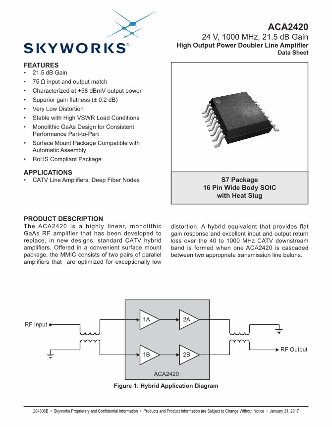
Figure 1: Hybrid Application Diagram
FEATURES• 21.5 dB Gain• 75Ωinputandoutputmatch• Characterizedat+58dBmVoutputpower• Superiorgainflatness(±0.2dB)• VeryLowDistortion• StablewithHighVSWRLoadConditions• MonolithicGaAsDesignforConsistent
PerformancePart-to-Part• SurfaceMountPackageCompatiblewith
AutomaticAssembly• RoHSCompliantPackage
APPLICATIONS• CATVLineAmplifiers,DeepFiberNodes S7 Package
16 Pin Wide Body SOICwith Heat Slug
PRODUCT DESCRIPTIONThe ACA2420 is a highly l inear, monolithicGaAs RF amplifier that has been developed toreplace, in new designs, standard CATV hybridamplifiers.Offered in a convenient surfacemountpackage,theMMICconsistsoftwopairsofparallelamplifiers that are optimized for exceptionally low
distortion.A hybrid equivalent that provides flatgainresponseandexcellentinputandoutputreturnloss over the 40 to 1000MHzCATVdownstream band is formedwhen oneACA2420 is cascadedbetweentwoappropriatetransmissionlinebaluns.
RF Input
RF Output
2A
2B1B
1A
ACA2420
2
ACA2420
Data SheetJanuary 31, 2017 • Skyworks Proprietary and Confidential Information • Products and Product Information are Subject to Change Without Notice • 204306B
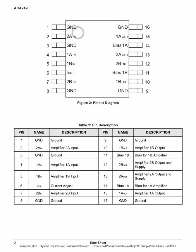
Figure 2: Pinout Diagram
Table 1: Pin Description
1
2
3
4
5
6
7
8
16
15
14
13
12
11
10
9
GND GND
ISET
2A IN
GND
2B IN
1BIN
1A IN
GND GND
1BOUT
2BOUT
2A OUT
1A OUT
Bias 1A
Bias 1B
PIN NAME DESCRIPTION PIN NAME DESCRIPTION
1 GND Ground 9 GND Ground
2 2AIN Amplifier2AInput 10 1BOUT Amplifier1BOutput
3 GND Ground 11 Bias1B Biasfor1BAmplifier
4 1AIN Amplifier1AInput 12 2BOUTAmplifier2BOutputandSupply
5 1BIN Amplifier1BInput 13 2AOUTAmplifier2AOutputandSupply
6 ISET CurrentAdjust 14 Bias1A Biasfor1AAmplifier
7 2BIN Amplifier2BInput 15 1AOUT Amplifier1AOutput
8 GND Ground 16 GND Ground

3
ACA2420
Data Sheet204306B• Skyworks Proprietary and Confidential Information • Products and Product Information are Subject to Change Without Notice • January 31, 2017
Table 2: Absolute Mimimum and Maximum Ratings
ELECTRICAL CHARACTERISTICS
Stresses in excess of the absolute ratings may cause permanent damage. Functional operation is not implied under these conditions. Exposure to absolute ratings for extended periods of time may adversely affect reliability.
Table 3: Operating Ranges
Notes:(1) Pins 2, 4, 5 and 7 should be AC-coupled. No external DC bias should be
applied.(2) Pin 6 should be AC-grounded and/or pulled to ground through a resistor for
current control. (3)Pins11and14arebiasfeedsforinputamplifiers1Aand1B.NoexternalDC
bias should be applied.(4) Pins 10 and 15 receive DC bias directly from pins 11 and 14.
The device may be operated safely over these conditions; however, parametric performance is guaranteed only over the conditions defined in the electrical specifications.
PARAMETER MIN MAX UNIT
Supply(pins12,13) 0 +28 VDC
CurrentAdjust(pin6) 0 +4 VDC
RFPoweratInputs(pins4,5) - +75 dBmV
StorageTemperature -65 +150 °C
SolderingTemperature - +260 °C
SolderingTime - 5.0 Sec
PARAMETER MIN TYP MAX UNIT
Supply: VDD (pins 12, 13) - +24 - VDC
Current Adjust (pin 6) - +1.5 - VDC
RF Frequency 40 - 1000 MHz
Case Temperature -40 - +100 °C

4
ACA2420
Data SheetJanuary 31, 2017 • Skyworks Proprietary and Confidential Information • Products and Product Information are Subject to Change Without Notice • 204306B
Table 4: AC and DC Electrical Specifications(Ta = +25 °C, Vdd = +24 VDC)
Notes:(1) Measured with baluns on the input and output of the device.(2)Partsmeasuredwith77channels,+58dBmVpower,15.5dBtiltat1000MHz.(3)Partsmeasuredwith77channels,+58dBmVpower,15.5dBtiltat1000MHz,plusQAMto1GHz.(4)AllspecificationsasmeasuredonEvaluationBoard(seeFigures13&14).
PARAMETER MIN TYP MAX UNIT COMMENTS
Gain @ 1000 MHz (1) 20.8 21.5 22.3 dB
Cable Equivalent Slope (1) -0.1 0 0.7 dB
Gain Flatness 50 to 1000 MHz - ±0.2 - dB
Noise Figure (1) - 5.75 6.5 dB
CTB (1)
77 Channels (2)
77 Channels (3)--
-78-76 -74
dBc
CSO (1)
77 Channels (2)
77 Channels (3)--
-71-69
--67
dBc
XMOD (1)
77 Channels (2)
77Channels (3)--
-64-63
--59
dBc
CIN (1)77 Channels (3) - - -58 dBc
Return Loss (Input) (1)
40-1000 MHz - -22 -18 dB 75 Ω system
Return Loss (Output) (1)
40-900 MHz901-1000 MHz
--
-22-22
-20-18 dB
Supply Current 495 520 545 mA
Thermal Resistance - 2.7 3.3 oC/W
(1)
-
75 Ω system
5
ACA2420
Data Sheet204306B• Skyworks Proprietary and Confidential Information • Products and Product Information are Subject to Change Without Notice • January 31, 2017
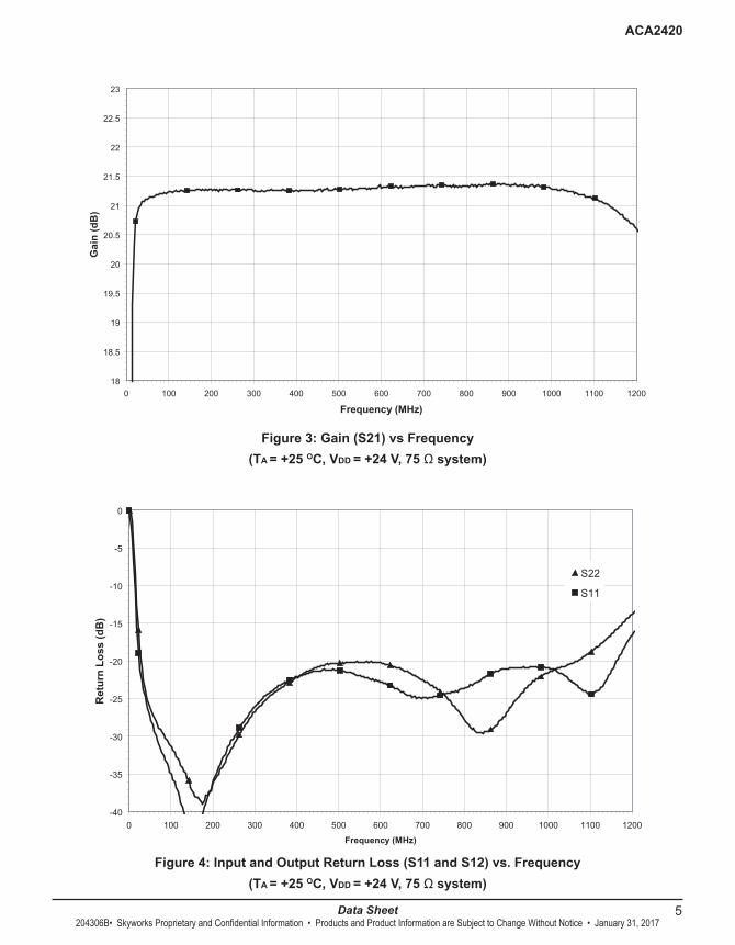
Figure 3: Gain (S21) vs Frequency(TA = +25 OC, VDD = +24 V, 75 Ω system)
Figure 4: Input and Output Return Loss (S11 and S12) vs. Frequency(TA = +25 OC, VDD = +24 V, 75 Ω system)
Figure 3: Gain (S21) vs Frequency(Ta=+25 C, Vdd=+24 V, 75 ohm system)
18
18.5
19
19.5
20
20.5
21
21.5
22
22.5
23
0 100 200 300 400 500 600 700 800 900 1000 1100 1200
Frequency (MHz)
Gai
n (d
B)
Figure 4: Input and Output Return Loss (S11 and S22) vs. Frequency(Ta=+25 C, Vdd= +24 V, 75 ohm system)
-40
-35
-30
-25
-20
-15
-10
-5
0
0 100 200 300 400 500 600 700 800 900 1000 1100 1200
Frequency (MHz)
Ret
urn
Loss
(dB
)
S22
S11
6
ACA2420
Data SheetJanuary 31, 2017 • Skyworks Proprietary and Confidential Information • Products and Product Information are Subject to Change Without Notice • 204306B
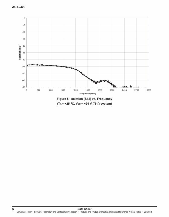
Figure 5: Isolation (S12) vs. Frequency(TA = +25 OC, VDD = +24 V, 75 Ω system)
Figure 5: Isolation (S12) vs. Frequency(Ta=+25 C, Vdd=+24 V, 75 ohm system)
-50
-45
-40
-35
-30
-25
-20
-15
-10
-5
0
0 300 600 900 1200 1500 1800 2100 2400 2700 3000
Frequency (MHz)
Isol
atio
n (d
B)
7
ACA2420
Data Sheet204306B• Skyworks Proprietary and Confidential Information • Products and Product Information are Subject to Change Without Notice • January 31, 2017
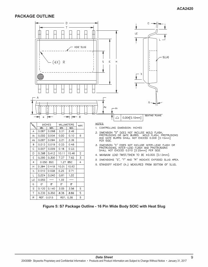
Figure 7: Evaluation Board Schematic
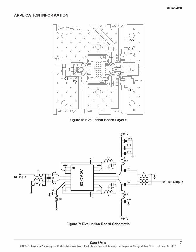
APPLICATION INFORMATION
Figure 6: Evaluation Board Layout
R3C11
C14
C15
TVS
C1
C2
C10
C14
L3C4
L4L2
L1
C5
C9
C8C6
C7
+24 V
+24 V
RF Input
RF Output
R3
T2T1
C11
C3
C15
AC
A2420
+
TVS

8
ACA2420
Data SheetJanuary 31, 2017 • Skyworks Proprietary and Confidential Information • Products and Product Information are Subject to Change Without Notice • 204306B
Table 5: Evaluation Board Parts List
Notes:(1) N connector center pin should be approximately 80 mils in length.(2) Due to the power dissipation of this device, the printed circuit board should be mounted / attached to a heat sink.
Figure 4: Balun Drawing
SCHEMATIC TOP VIEW SIDE VIEW
Note:See M/A-COM’s data sheet for more details.
REFERENCE DESCRIPTION QTY VENDOR VENDOR P/N
C1, C2, C3, C6,C7, C10, C14 0.01uFCHIPCAP 7 MURATA GRM39X7R103K50V
C4,C5,C8,C9 270pFCHIPCAP 4 MURATA GRM39X7R271K50V
C11 1.0pFCHIPCAP 1 MURATA GRM36COG0R5C50
C15 47uFELECTCAP 1 DIGI-KEYCORP P5275-ND
C12,C13,R2,R3 NOTUSED
TVS TVS24VOLT600WATT 1 DIGI-KEYCORP SMBJ24ACCCT-ND
L1,L2,L3,L4 470nHINDUCTOR 4 MURATA LQH1WA47KONO003/-4052
R3 15KOhm 1 - -
CONNECTOR(1) 75OhmNMALEPANELMOUNT 2 PASTERNACK
ENTERPRISES PE4504
T1,T2 Balun 2 M/A-COM MABA-009210-CT1760
PrintedCircuitBoard(2) 1STANDARDPRINTEDCIRC.INC.
24VX1AC50
9
ACA2420
Data Sheet204306B• Skyworks Proprietary and Confidential Information • Products and Product Information are Subject to Change Without Notice • January 31, 2017
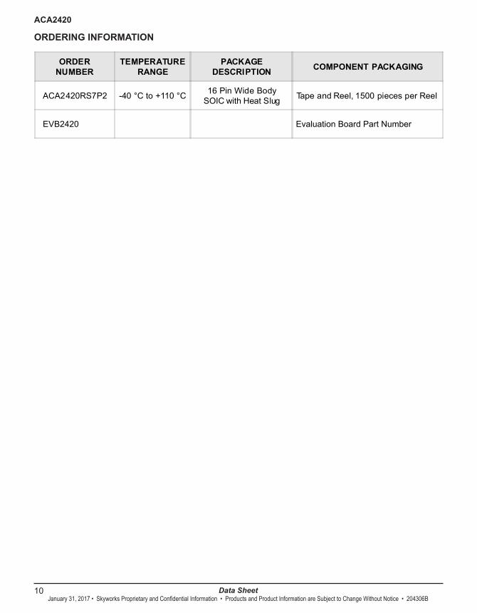
Figure 5: S7 Package Outline - 16 Pin Wide Body SOIC with Heat Slug
PACKAGE OUTLINE
10
ACA2420
Data SheetJanuary 31, 2017 • Skyworks Proprietary and Confidential Information • Products and Product Information are Subject to Change Without Notice • 204306B
ORDERING INFORMATION
ORDERNUMBER
TEMPERATURERANGE
PACKAGEDESCRIPTION COMPONENT PACKAGING
ACA2420RS7P2 -40 °Cto+110 °C 16 PinWideBodySOICwithHeat Slug Tape andReel, 1500 piecesperReel
EVB2420 EvaluationBoardPartNumber

11
ACA2420
Data Sheet204306B• Skyworks Proprietary and Confidential Information • Products and Product Information are Subject to Change Without Notice • January 31, 2017
NOTES

12
ACA2420
Data Sheet204306B • January 31, 2017
Copyright © 2016-2017 Skyworks Solutions, Inc. All Rights Reserved.
Information in this document is provided in connection with Skyworks Solutions, Inc. (“Skyworks”) products or services. These materials, including the information contained herein, are provided by Skyworks as a service to its customers and may be used for informational purposes only by the customer. Skyworks assumes no responsibility for errors or omissions in these materials or the information contained herein. Skyworks may change its documentation, products, services, specifications or product descriptions at any time, without notice. Skyworks makes no commitment to update the materials or information and shall have no responsibility whatsoever for conflicts, incompatibilities, or other difficulties arising from any future changes.
No license, whether express, implied, by estoppel or otherwise, is granted to any intellectual property rights by this document. Skyworks assumes no liability for any materials, products or information provided hereunder, including the sale, distribution, reproduction or use of Skyworks products, information or materials, except as may be provided in Skyworks Terms and Conditions of Sale.
THE MATERIALS, PRODUCTS AND INFORMATION ARE PROVIDED “AS IS” WITHOUT WARRANTY OF ANY KIND, WHETHER EXPRESS, IMPLIED, STATUTORY, OR OTHERWISE, INCLUDING FITNESS FOR A PARTICULAR PURPOSE OR USE, MERCHANTABILITY, PERFORMANCE, QUALITY OR NON-INFRINGEMENT OF ANY INTELLECTUAL PROPERTY RIGHT; ALL SUCH WARRANTIES ARE HEREBY EXPRESSLY DISCLAIMED. SKYWORKS DOES NOT WARRANT THE ACCURACY OR COMPLETENESS OF THE INFORMATION, TEXT, GRAPHICS OR OTHER ITEMS CONTAINED WITHIN THESE MATERIALS. SKYWORKS SHALL NOT BE LIABLE FOR ANY DAMAGES, INCLUDING BUT NOT LIMITED TO ANY SPECIAL, INDIRECT, INCIDENTAL, STATUTORY, OR CONSEQUENTIAL DAMAGES, INCLUDING WITHOUT LIMITATION, LOST REVENUES OR LOST PROFITS THAT MAY RESULT FROM THE USE OF THE MATERIALS OR INFORMATION, WHETHER OR NOT THE RECIPIENT OF MATERIALS HAS BEEN ADVISED OF THE POSSIBILITY OF SUCH DAMAGE.
Skyworks products are not intended for use in medical, lifesaving or life-sustaining applications, or other equipment in which the failure of the Skyworks products could lead to personal injury, death, physical or environmental damage. Skyworks cus-tomers using or selling Skyworks products for use in such applications do so at their own risk and agree to fully indemnify Skyworks for any damages resulting from such improper use or sale.Customers are responsible for their products and applications using Skyworks products, which may deviate from published specifications as a result of design defects, errors, or operation of products outside of published parameters or design specifications.
Customers should include design and operating safeguards to minimize these and other risks. Skyworks assumes no liabil-ity for applications assistance, customer product design, or damage to any equipment resulting from the use of Skyworks products outside of stated published specifications or parameters.
Skyworks and the Skyworks symbol are trademarks or registered trademarks of Skyworks Solutions, Inc., in the United States and other countries. Third-party brands and names are for identification purposes only, and are the property of their respective owners. Additional information, including relevant terms and conditions, posted at www.skyworksinc.com, are incorporated by reference.
Skyworks Solutions, Inc. Phone [781] 376-3000 • Fax [781] 376-3100 • [email protected] • www.skyworksinc.com
Skyworks Proprietary and Confidential information • Products and Product Information are Subject to Change Without Notice