accelerated creep testing of high strength aramid … · accelerated creep testing of high ... a...
TRANSCRIPT
American Institute of Aeronautics and Astronautics
1
Accelerated Creep Testing of High Strength Aramid Webbing
Thomas C. Jones1, William R. Doggett2 and Clarence E. Stanfield3 NASA Langley Research Center, Hampton, VA, 23681
and
Omar Valverde4 Georgia Institute of Technology, Atlanta, GA, 30332
A series of preliminary accelerated creep tests were performed on four variants of 12K and 24K lbf rated Vectran webbing to help develop an accelerated creep test methodology and analysis capability for high strength aramid webbings. The variants included pristine, aged, folded and stitched samples. This class of webbings is used in the restraint layer of habitable, inflatable space structures, for which the lifetime properties are currently not well characterized. The Stepped Isothermal Method was used to accelerate the creep life of the webbings and a novel stereo photogrammetry system was used to measure the full-field strains. A custom MATLAB code is described, and used to reduce the strain data to produce master creep curves for the test samples. Initial results show good correlation between replicates; however, it is clear that a larger number of samples are needed to build confidence in the consistency of the results. It is noted that local fiber breaks affect the creep response in a similar manner to increasing the load, thus raising the creep rate and reducing the time to creep failure. The stitched webbings produced the highest variance between replicates, due to the combination of higher local stresses and thread-on-fiber damage. Large variability in the strength of the webbings is also shown to have an impact on the range of predicted creep life.
I. Introduction ABITABLE, inflatable space structures are an enabling technology for human exploration in space and on planetary surfaces. Large primary volumes for living and working can be deployed, while providing high
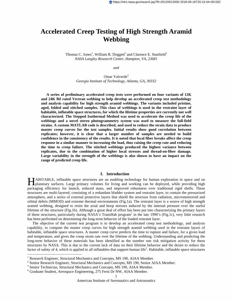
packaging efficiency for launch, reduced mass, and improved robustness over traditional rigid shells. These structures are multi-layered, consisting of a redundant bladder system and restraint layer, to contain the pressurized atmosphere, and a series of external protective layers that shield the structure from radiation, micrometeoroid and orbital debris (MMOD) and extreme thermal environments (Fig.1a). The restraint layer is a weave of high strength aramid webbing, designed to resist the axial and hoop stresses induced by the internal pressure over the useful lifetime of the structure (Fig.1b). Although a great deal of effort has been put into characterizing the primary layers of these structures, particularly during NASA’s TransHab program1 in the late 1990’s (Fig.1c), very little research has been performed on determining the long-term behavior of the loaded restraint layer.
The objective of the current test program is to develop an accelerated creep test methodology, and analysis capability, to compute the master creep curves for high strength aramid webbing used in the restraint layers of habitable, inflatable space structures. A master creep curve predicts the time to rupture and failure, for a given load and temperature, and gives the creep strain rate over the lifetime of the webbing. Understanding and predicting the long-term behavior of these materials has been identified as the number one risk mitigation activity for these structures by NASA. This is due to the current lack of data on their lifetime behavior and the desire to reduce the factor of safety of 4, which is applied to all inflatables that support human life2. Habitable, inflatable space structures 1 Research Engineer, Structural Mechanics and Concepts, MS 190, AIAA Member. 2 Senior Research Engineer, Structural Mechanics and Concepts, MS 190, Senior AIAA Member. 3 Senior Technician, Structural Mechanics and Concepts, MS 190, AIAA Member. 4 Graduate Student, Aerospace Engineering, 275 Ferst Dr NW, AIAA Member.
H
https://ntrs.nasa.gov/search.jsp?R=20120012000 2018-09-16T20:15:44+00:00Z
American Institute of Aeronautics and Astronautics
2
are currently designed using the restraint layer’s pristine properties, with the high factor of safety being applied, principally due to the uncertainty in the change in mechanical properties after 5 to 15 years of continuous service. Creep is the primary mechanism of degradation of the restraint layer over time, and is therefore the core focus of ongoing material testing.
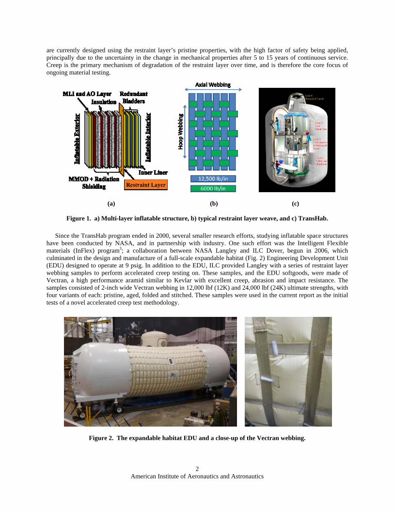
Since the TransHab program ended in 2000, several smaller research efforts, studying inflatable space structures have been conducted by NASA, and in partnership with industry. One such effort was the Intelligent Flexible materials (InFlex) program3; a collaboration between NASA Langley and ILC Dover, begun in 2006, which culminated in the design and manufacture of a full-scale expandable habitat (Fig. 2) Engineering Development Unit (EDU) designed to operate at 9 psig. In addition to the EDU, ILC provided Langley with a series of restraint layer webbing samples to perform accelerated creep testing on. These samples, and the EDU softgoods, were made of Vectran, a high performance aramid similar to Kevlar with excellent creep, abrasion and impact resistance. The samples consisted of 2-inch wide Vectran webbing in 12,000 lbf (12K) and 24,000 lbf (24K) ultimate strengths, with four variants of each: pristine, aged, folded and stitched. These samples were used in the current report as the initial tests of a novel accelerated creep test methodology.
(a) (b) (c)
Figure 1. a) Multi-layer inflatable structure, b) typical restraint layer weave, and c) TransHab.
Figure 2. The expandable habitat EDU and a close-up of the Vectran webbing.
American Institute of Aeronautics and Astronautics
3
II. Test Methodology, Instrumentation and Facilities Several previous studies examined the creep behavior of single aramid fibers, and it was shown that the creep
behavior of these materials could be thermally accelerated4, 5. Two primary methods are used in the literature to reduce the raw strain data from the accelerated creep tests into a final master creep curve for a given constant load and initial temperature. These are the Stepped Isothermal Method (SIM)6-8 and the Time-Temperature Superposition method (TTS)9-12. Both methods apply the principle that the viscoelastic strain behavior of a polymer, such as an aramid, has a strong time-temperature dependence; increasing temperature has the effect of contracting the time to failure in an exponential manner. Additionally, the strain versus time curves at different temperatures follow the same logarithmic relationship with a constant activation energy. Thus, if the strain is plotted versus log(time) for samples run at different temperatures, the curves can be superimposed to form one continuous and complete master creep curve.
The TTS method requires multiple tests to be run at different temperatures to form the master creep curve, whereas the SIM utilizes a single specimen, run at multiple increasing temperature steps. The SIM does require two additional steps in post-processing to account for the changes in temperature and the creep that has taken place during previous temperature steps. However, the SIM has three major advantages over TTS: (1) the sample reaches failure much quicker due to the higher temperature steps in every test case; (2) multiple master creep curves are obtained from a small number of samples, providing statistically relevant results; and (3) the test avoids the added variance of creating one master curve from multiple specimens. For these reasons the SIM was chosen for the current study.
Measuring the strain in the fabric webbing required a novel approach that was the result of testing several measurement techniques. Initial tests utilized pin-contact extensometers that required penetration through the webbing. It was quickly determined that even the smallest needles created a stress concentration in the highly loaded webbing that often lead to failure of the specimen at that location. The second approach would have been to use the displacement data from the load frame to derive the strains. However, given the uncertainty introduced by grip effects, possible slippage in the webbing, and the difficulty in determining the effective initial length of a specimen, this approach was not pursued. The chosen methodology implements stereo photogrammetry to determine the full-field three-dimensional displacements and strains of the webbing test section.
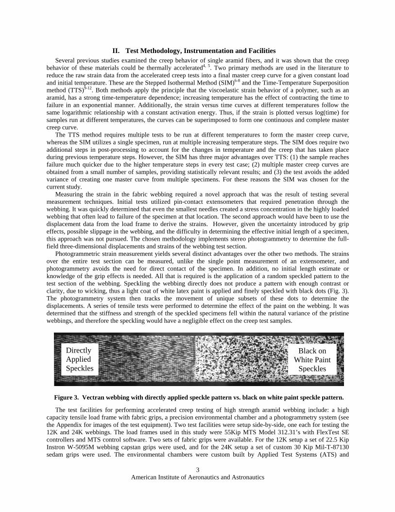
Photogrammetric strain measurement yields several distinct advantages over the other two methods. The strains over the entire test section can be measured, unlike the single point measurement of an extensometer, and photogrammetry avoids the need for direct contact of the specimen. In addition, no initial length estimate or knowledge of the grip effects is needed. All that is required is the application of a random speckled pattern to the test section of the webbing. Speckling the webbing directly does not produce a pattern with enough contrast or clarity, due to wicking, thus a light coat of white latex paint is applied and finely speckled with black dots (Fig. 3). The photogrammetry system then tracks the movement of unique subsets of these dots to determine the displacements. A series of tensile tests were performed to determine the effect of the paint on the webbing. It was determined that the stiffness and strength of the speckled specimens fell within the natural variance of the pristine webbings, and therefore the speckling would have a negligible effect on the creep test samples.
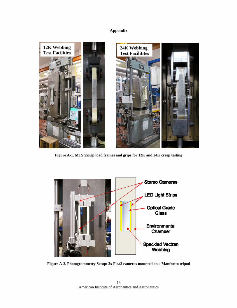
The test facilities for performing accelerated creep testing of high strength aramid webbing include: a high
capacity tensile load frame with fabric grips, a precision environmental chamber and a photogrammetry system (see the Appendix for images of the test equipment). Two test facilities were setup side-by-side, one each for testing the 12K and 24K webbings. The load frames used in this study were 55Kip MTS Model 312.31’s with FlexTest SE controllers and MTS control software. Two sets of fabric grips were available. For the 12K setup a set of 22.5 Kip Instron W-5095M webbing capstan grips were used, and for the 24K setup a set of custom 30 Kip Mil-T-87130 sedam grips were used. The environmental chambers were custom built by Applied Test Systems (ATS) and
Figure 3. Vectran webbing with directly applied speckle pattern vs. black on white paint speckle pattern.
Directly Applied Speckles
Black on White Paint
Speckles
American Institute of Aeronautics and Astronautics
4
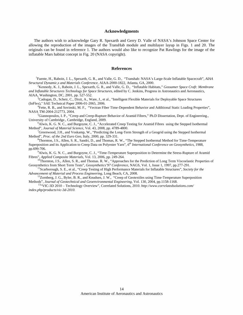
Thermcraft and were designed to hold temperature to within ±2 ºC and allow for a temperature ramp of 5 ºC / minute. An optical grade glass window in each oven allowed photogrammetric measurements and 12V LED light strips were attached along the edges of the windows to evenly illuminate the samples. Each photogrammetry system used two Point Grey B&W Flea-2, 5 Megapixel cameras mounted one above the other on a 1.5-inch square beam attached to a Manfrotto 161MK2B professional tripod. Pulses sent from the MTS controller triggered the system, recording a set of two images every minute for the duration of the test. The photogrammetry systems had dedicated computers to run the Visual Image Correlation (VIC3D) software13 and record the images from the cameras.
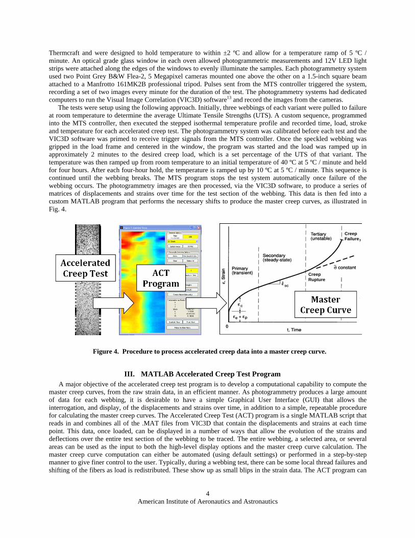
The tests were setup using the following approach. Initially, three webbings of each variant were pulled to failure at room temperature to determine the average Ultimate Tensile Strengths (UTS). A custom sequence, programmed into the MTS controller, then executed the stepped isothermal temperature profile and recorded time, load, stroke and temperature for each accelerated creep test. The photogrammetry system was calibrated before each test and the VIC3D software was primed to receive trigger signals from the MTS controller. Once the speckled webbing was gripped in the load frame and centered in the window, the program was started and the load was ramped up in approximately 2 minutes to the desired creep load, which is a set percentage of the UTS of that variant. The temperature was then ramped up from room temperature to an initial temperature of 40 ºC at 5 ºC / minute and held for four hours. After each four-hour hold, the temperature is ramped up by 10 ºC at 5 ºC / minute. This sequence is continued until the webbing breaks. The MTS program stops the test system automatically once failure of the webbing occurs. The photogrammetry images are then processed, via the VIC3D software, to produce a series of matrices of displacements and strains over time for the test section of the webbing. This data is then fed into a custom MATLAB program that performs the necessary shifts to produce the master creep curves, as illustrated in Fig. 4.
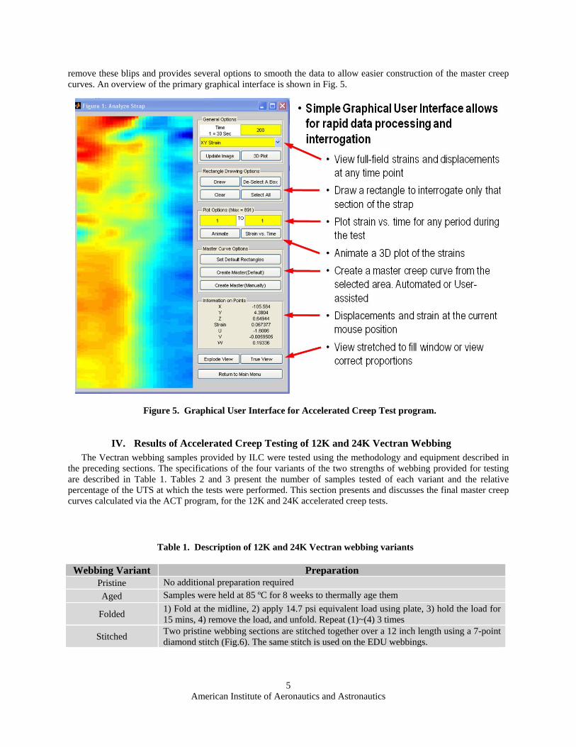
III. MATLAB Accelerated Creep Test Program A major objective of the accelerated creep test program is to develop a computational capability to compute the
master creep curves, from the raw strain data, in an efficient manner. As photogrammetry produces a large amount of data for each webbing, it is desirable to have a simple Graphical User Interface (GUI) that allows the interrogation, and display, of the displacements and strains over time, in addition to a simple, repeatable procedure for calculating the master creep curves. The Accelerated Creep Test (ACT) program is a single MATLAB script that reads in and combines all of the .MAT files from VIC3D that contain the displacements and strains at each time point. This data, once loaded, can be displayed in a number of ways that allow the evolution of the strains and deflections over the entire test section of the webbing to be traced. The entire webbing, a selected area, or several areas can be used as the input to both the high-level display options and the master creep curve calculation. The master creep curve computation can either be automated (using default settings) or performed in a step-by-step manner to give finer control to the user. Typically, during a webbing test, there can be some local thread failures and shifting of the fibers as load is redistributed. These show up as small blips in the strain data. The ACT program can
Figure 4. Procedure to process accelerated creep data into a master creep curve.
Creep Failure
Creep Rupture
American Institute of Aeronautics and Astronautics
5
remove these blips and provides several options to smooth the data to allow easier construction of the master creep curves. An overview of the primary graphical interface is shown in Fig. 5.
IV. Results of Accelerated Creep Testing of 12K and 24K Vectran Webbing The Vectran webbing samples provided by ILC were tested using the methodology and equipment described in
the preceding sections. The specifications of the four variants of the two strengths of webbing provided for testing are described in Table 1. Tables 2 and 3 present the number of samples tested of each variant and the relative percentage of the UTS at which the tests were performed. This section presents and discusses the final master creep curves calculated via the ACT program, for the 12K and 24K accelerated creep tests.
Figure 5. Graphical User Interface for Accelerated Creep Test program.
Table 1. Description of 12K and 24K Vectran webbing variants
Webbing Variant Preparation Pristine No additional preparation required
Aged Samples were held at 85 ºC for 8 weeks to thermally age them
Folded 1) Fold at the midline, 2) apply 14.7 psi equivalent load using plate, 3) hold the load for 15 mins, 4) remove the load, and unfold. Repeat (1)~(4) 3 times
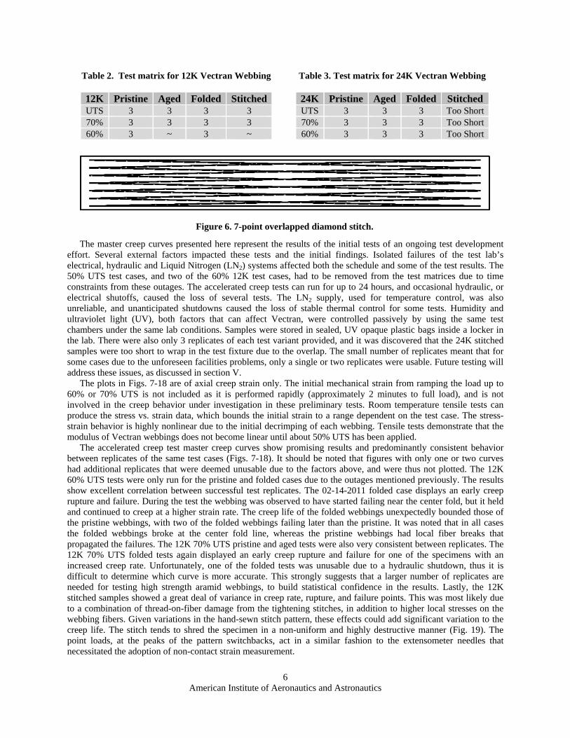
Stitched Two pristine webbing sections are stitched together over a 12 inch length using a 7-point diamond stitch (Fig.6). The same stitch is used on the EDU webbings.
American Institute of Aeronautics and Astronautics
6
The master creep curves presented here represent the results of the initial tests of an ongoing test development
effort. Several external factors impacted these tests and the initial findings. Isolated failures of the test lab’s electrical, hydraulic and Liquid Nitrogen (LN2) systems affected both the schedule and some of the test results. The 50% UTS test cases, and two of the 60% 12K test cases, had to be removed from the test matrices due to time constraints from these outages. The accelerated creep tests can run for up to 24 hours, and occasional hydraulic, or electrical shutoffs, caused the loss of several tests. The LN2 supply, used for temperature control, was also unreliable, and unanticipated shutdowns caused the loss of stable thermal control for some tests. Humidity and ultraviolet light (UV), both factors that can affect Vectran, were controlled passively by using the same test chambers under the same lab conditions. Samples were stored in sealed, UV opaque plastic bags inside a locker in the lab. There were also only 3 replicates of each test variant provided, and it was discovered that the 24K stitched samples were too short to wrap in the test fixture due to the overlap. The small number of replicates meant that for some cases due to the unforeseen facilities problems, only a single or two replicates were usable. Future testing will address these issues, as discussed in section V.
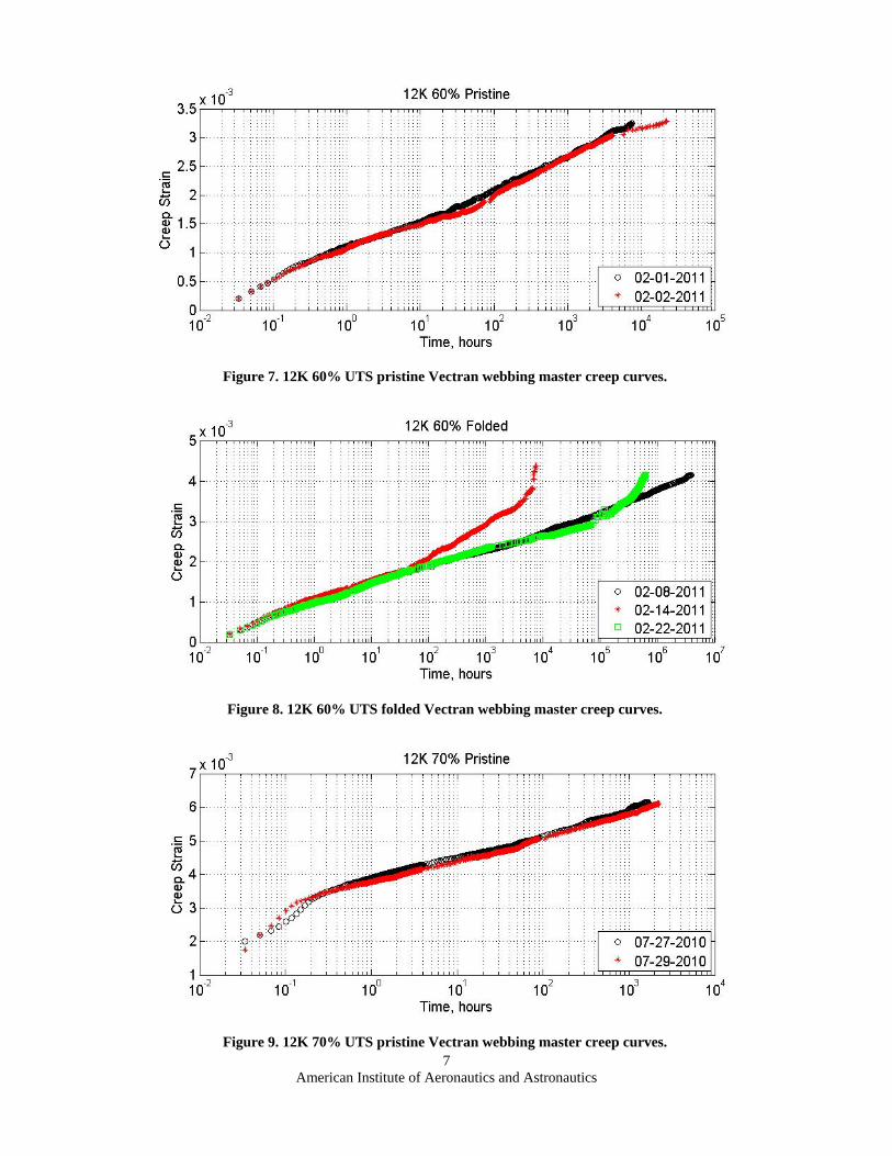
The plots in Figs. 7-18 are of axial creep strain only. The initial mechanical strain from ramping the load up to 60% or 70% UTS is not included as it is performed rapidly (approximately 2 minutes to full load), and is not involved in the creep behavior under investigation in these preliminary tests. Room temperature tensile tests can produce the stress vs. strain data, which bounds the initial strain to a range dependent on the test case. The stress-strain behavior is highly nonlinear due to the initial decrimping of each webbing. Tensile tests demonstrate that the modulus of Vectran webbings does not become linear until about 50% UTS has been applied.
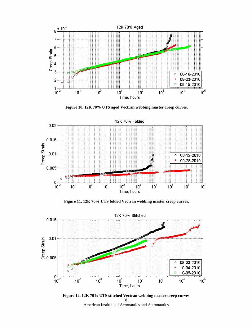
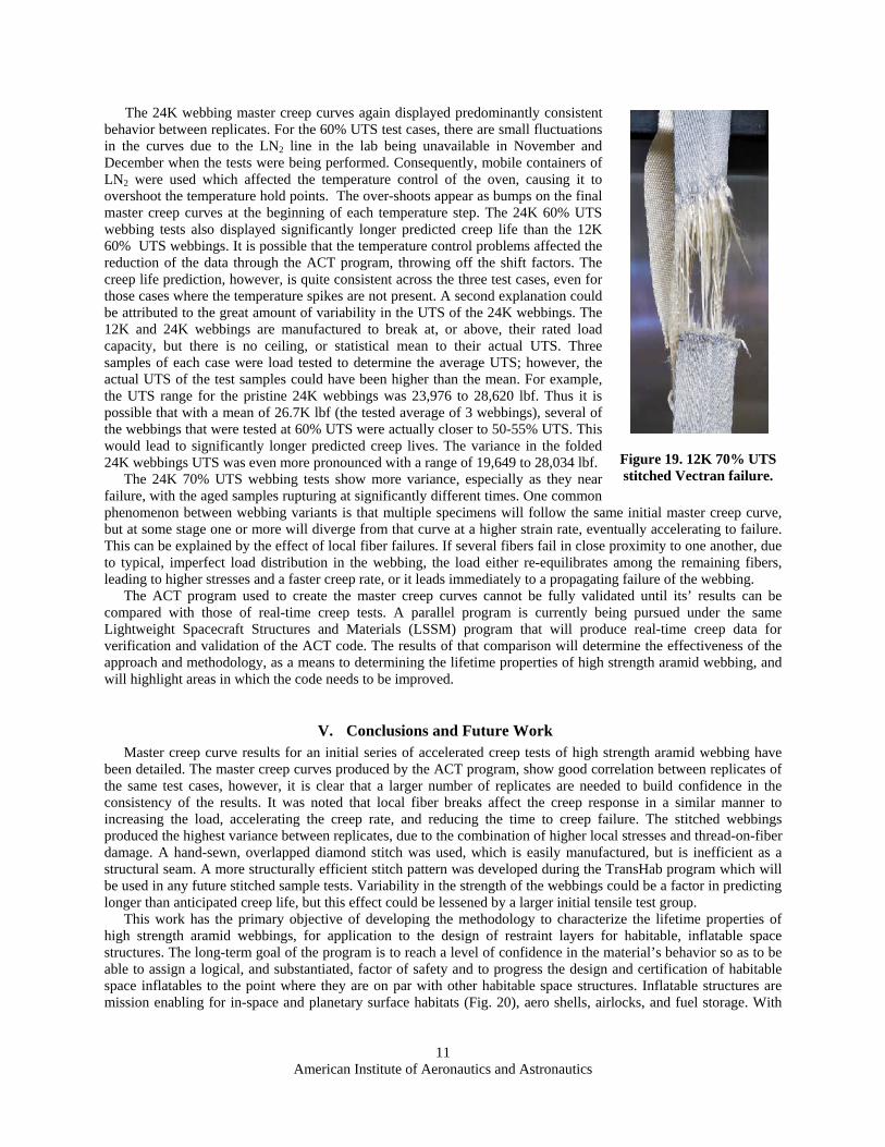
The accelerated creep test master creep curves show promising results and predominantly consistent behavior between replicates of the same test cases (Figs. 7-18). It should be noted that figures with only one or two curves had additional replicates that were deemed unusable due to the factors above, and were thus not plotted. The 12K 60% UTS tests were only run for the pristine and folded cases due to the outages mentioned previously. The results show excellent correlation between successful test replicates. The 02-14-2011 folded case displays an early creep rupture and failure. During the test the webbing was observed to have started failing near the center fold, but it held and continued to creep at a higher strain rate. The creep life of the folded webbings unexpectedly bounded those of the pristine webbings, with two of the folded webbings failing later than the pristine. It was noted that in all cases the folded webbings broke at the center fold line, whereas the pristine webbings had local fiber breaks that propagated the failures. The 12K 70% UTS pristine and aged tests were also very consistent between replicates. The 12K 70% UTS folded tests again displayed an early creep rupture and failure for one of the specimens with an increased creep rate. Unfortunately, one of the folded tests was unusable due to a hydraulic shutdown, thus it is difficult to determine which curve is more accurate. This strongly suggests that a larger number of replicates are needed for testing high strength aramid webbings, to build statistical confidence in the results. Lastly, the 12K stitched samples showed a great deal of variance in creep rate, rupture, and failure points. This was most likely due to a combination of thread-on-fiber damage from the tightening stitches, in addition to higher local stresses on the webbing fibers. Given variations in the hand-sewn stitch pattern, these effects could add significant variation to the creep life. The stitch tends to shred the specimen in a non-uniform and highly destructive manner (Fig. 19). The point loads, at the peaks of the pattern switchbacks, act in a similar fashion to the extensometer needles that necessitated the adoption of non-contact strain measurement.
Table 2. Test matrix for 12K Vectran Webbing
12K Pristine Aged Folded StitchedUTS 3 3 3 3 70% 3 3 3 3 60% 3 ~ 3 ~
Table 3. Test matrix for 24K Vectran Webbing
24K Pristine Aged Folded Stitched UTS 3 3 3 Too Short70% 3 3 3 Too Short60% 3 3 3 Too Short
Figure 6. 7-point overlapped diamond stitch.
American Institute of Aeronautics and Astronautics
7
Figure 7. 12K 60% UTS pristine Vectran webbing master creep curves.
Figure 8. 12K 60% UTS folded Vectran webbing master creep curves.
Figure 9. 12K 70% UTS pristine Vectran webbing master creep curves.
American Institute of Aeronautics and Astronautics
8
Figure 10. 12K 70% UTS aged Vectran webbing master creep curves.
Figure 11. 12K 70% UTS folded Vectran webbing master creep curves.
Figure 12. 12K 70% UTS stitched Vectran webbing master creep curves.
American Institute of Aeronautics and Astronautics
9
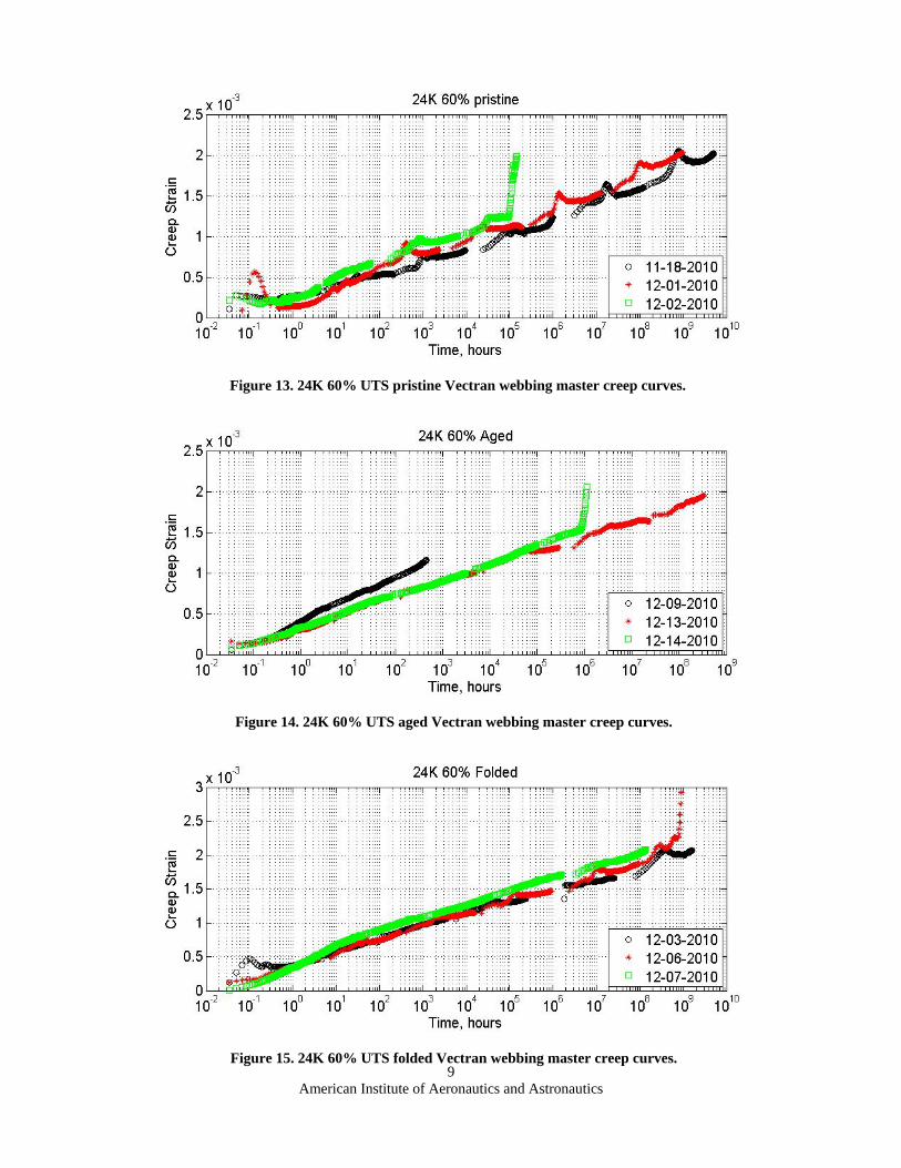
Figure 13. 24K 60% UTS pristine Vectran webbing master creep curves.
Figure 14. 24K 60% UTS aged Vectran webbing master creep curves.
Figure 15. 24K 60% UTS folded Vectran webbing master creep curves.
American Institute of Aeronautics and Astronautics
10
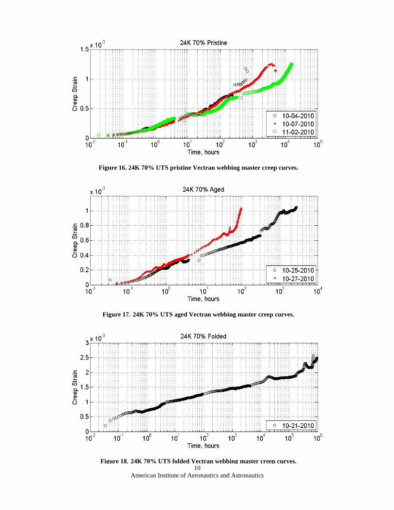
Figure 16. 24K 70% UTS pristine Vectran webbing master creep curves.
Figure 17. 24K 70% UTS aged Vectran webbing master creep curves.
Figure 18. 24K 70% UTS folded Vectran webbing master creep curves.
American Institute of Aeronautics and Astronautics
11
Figure 19. 12K 70% UTS stitched Vectran failure.
The 24K webbing master creep curves again displayed predominantly consistent behavior between replicates. For the 60% UTS test cases, there are small fluctuations in the curves due to the LN2 line in the lab being unavailable in November and December when the tests were being performed. Consequently, mobile containers of LN2 were used which affected the temperature control of the oven, causing it to overshoot the temperature hold points. The over-shoots appear as bumps on the final master creep curves at the beginning of each temperature step. The 24K 60% UTS webbing tests also displayed significantly longer predicted creep life than the 12K 60% UTS webbings. It is possible that the temperature control problems affected the reduction of the data through the ACT program, throwing off the shift factors. The creep life prediction, however, is quite consistent across the three test cases, even for those cases where the temperature spikes are not present. A second explanation could be attributed to the great amount of variability in the UTS of the 24K webbings. The 12K and 24K webbings are manufactured to break at, or above, their rated load capacity, but there is no ceiling, or statistical mean to their actual UTS. Three samples of each case were load tested to determine the average UTS; however, the actual UTS of the test samples could have been higher than the mean. For example, the UTS range for the pristine 24K webbings was 23,976 to 28,620 lbf. Thus it is possible that with a mean of 26.7K lbf (the tested average of 3 webbings), several of the webbings that were tested at 60% UTS were actually closer to 50-55% UTS. This would lead to significantly longer predicted creep lives. The variance in the folded 24K webbings UTS was even more pronounced with a range of 19,649 to 28,034 lbf.
The 24K 70% UTS webbing tests show more variance, especially as they near failure, with the aged samples rupturing at significantly different times. One common phenomenon between webbing variants is that multiple specimens will follow the same initial master creep curve, but at some stage one or more will diverge from that curve at a higher strain rate, eventually accelerating to failure. This can be explained by the effect of local fiber failures. If several fibers fail in close proximity to one another, due to typical, imperfect load distribution in the webbing, the load either re-equilibrates among the remaining fibers, leading to higher stresses and a faster creep rate, or it leads immediately to a propagating failure of the webbing.
The ACT program used to create the master creep curves cannot be fully validated until its’ results can be compared with those of real-time creep tests. A parallel program is currently being pursued under the same Lightweight Spacecraft Structures and Materials (LSSM) program that will produce real-time creep data for verification and validation of the ACT code. The results of that comparison will determine the effectiveness of the approach and methodology, as a means to determining the lifetime properties of high strength aramid webbing, and will highlight areas in which the code needs to be improved.
V. Conclusions and Future Work Master creep curve results for an initial series of accelerated creep tests of high strength aramid webbing have
been detailed. The master creep curves produced by the ACT program, show good correlation between replicates of the same test cases, however, it is clear that a larger number of replicates are needed to build confidence in the consistency of the results. It was noted that local fiber breaks affect the creep response in a similar manner to increasing the load, accelerating the creep rate, and reducing the time to creep failure. The stitched webbings produced the highest variance between replicates, due to the combination of higher local stresses and thread-on-fiber damage. A hand-sewn, overlapped diamond stitch was used, which is easily manufactured, but is inefficient as a structural seam. A more structurally efficient stitch pattern was developed during the TransHab program which will be used in any future stitched sample tests. Variability in the strength of the webbings could be a factor in predicting longer than anticipated creep life, but this effect could be lessened by a larger initial tensile test group.
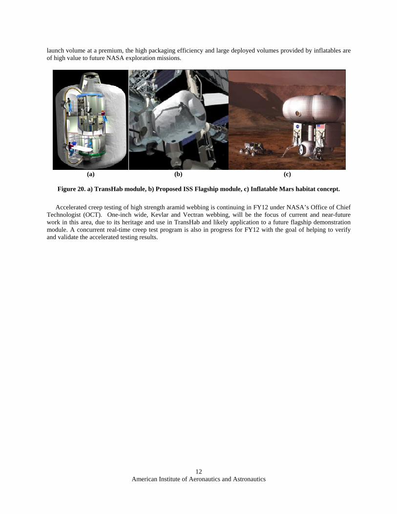
This work has the primary objective of developing the methodology to characterize the lifetime properties of high strength aramid webbings, for application to the design of restraint layers for habitable, inflatable space structures. The long-term goal of the program is to reach a level of confidence in the material’s behavior so as to be able to assign a logical, and substantiated, factor of safety and to progress the design and certification of habitable space inflatables to the point where they are on par with other habitable space structures. Inflatable structures are mission enabling for in-space and planetary surface habitats (Fig. 20), aero shells, airlocks, and fuel storage. With
American Institute of Aeronautics and Astronautics
12
launch volume at a premium, the high packaging efficiency and large deployed volumes provided by inflatables are of high value to future NASA exploration missions.
Accelerated creep testing of high strength aramid webbing is continuing in FY12 under NASA’s Office of Chief
Technologist (OCT). One-inch wide, Kevlar and Vectran webbing, will be the focus of current and near-future work in this area, due to its heritage and use in TransHab and likely application to a future flagship demonstration module. A concurrent real-time creep test program is also in progress for FY12 with the goal of helping to verify and validate the accelerated testing results.
(a) (b) (c)
Figure 20. a) TransHab module, b) Proposed ISS Flagship module, c) Inflatable Mars habitat concept.
American Institute of Aeronautics and Astronautics
13
Appendix
Figure A-1. MTS 55Kip load frames and grips for 12K and 24K creep testing
12K Webbing Test Facilities
24K Webbing Test Facilitites
Figure A-2. Photogrammetry Setup: 2x Flea2 cameras mounted on a Manfrotto tripod
American Institute of Aeronautics and Astronautics
14
Acknowledgments The authors wish to acknowledge Gary R. Spexarth and Gerry D. Valle of NASA’s Johnson Space Center for
allowing the reproduction of the images of the TransHab module and multilayer layup in Figs. 1 and 20. The originals can be found in reference 1. The authors would also like to recognize Pat Rawlings for the image of the inflatable Mars habitat concept in Fig. 20 (NASA copyright).
References
1Fuente, H., Raboin, J. L., Spexarth, G. R., and Valle, G. D., “Transhab: NASA’s Large-Scale Inflatable Spacecraft”, AIAA Structural Dynamic,s and Materials Conference, AIAA-2000-1822, Atlanta, GA, 2000.
2Kennedy, K. J., Raboin, J. L., Spexarth, G. R., and Valle, G. D., “Inflatable Habitats,” Gossamer Space Craft: Membrane and Inflatable Structures Technology for Space Structures, edited by C. Jenkins, Progress in Astronautics and Aeronautics, AIAA, Washington, DC, 2001, pp. 527-552.
3Cadogan, D., Scheir, C., Dixit, A., Ware, J., et al., "Intelligent Flexible Materials for Deployable Space Structures (InFlex)," SAE Technical Paper 2006-01-2065, 2006.
4Fette, R. B., and Sovinski, M. F., “Vectran Fiber Time-Dependent Behavior and Additional Static Loading Properties”, NASA TM-2004-212773, 2004.
5Giannopoulos, I. P., “Creep and Creep-Rupture Behavior of Aramid Fibres,” Ph.D Dissertation, Dept. of Engineering., University of Cambridge., Cambridge, England, 2009.
6Alwis, K. G. N. C., and Burgoyne, C. J., “Accelerated Creep Testing for Aramid Fibres using the Stepped Isothermal Method”, Journal of Material Science, Vol. 43, 2008, pp. 4789-4800.
7Greenwood, J.H., and Voskamp, W., “Predicting the Long-Term Strength of a Geogrid using the Stepped Isothermal Method”, Proc. of the 2nd Euro Geo, Italy, 2000, pp. 329-331.
8Thornton, J.S., Allen, S. R., Sandri, D., and Thomas, R. W., “The Stepped Isothermal Method for Time-Temperature Superposition and its Application to Creep Data on Polyester Yarn”, 6th International Conference on Geosynthetics, 1988, pp.699-706.
9Alwis, K. G. N. C., and Burgoyne, C. J., “Time-Temperature Superposition to Determine the Stress-Rupture of Aramid Fibres”, Applied Composite Materials, Vol. 13, 2006, pp. 249-264.
10Thornton, J.S., Allen, S. R., and Thomas. R. W., “Approaches for the Prediction of Long Term Viscoelastic Properties of Geosynthetics from Short Term Tests”, Geosynthetics’97 Conference, NAGS, Vol. 1, Issue 1, 1997, pp.277-291.
11Scarborough, S. E., et al., “Creep Testing of High Performance Materials for Inflatable Structures”, Society for the Advancement of Material and Process Engineering, Long Beach, CA, 2008.
12Zornberg, J. G., Byler, B. R., and Knudsen, J. W., “Creep of Geotextiles using Time-Temperature Superposition Methods”, Journal of Geotechnical and Geoenvironmental Engineering, Vol. 130, 2004, pp.1158-1168.
13“VIC-3D 2010 – Technology Overview”, Correlated Solutions, 2010. http://www.correlatedsolutions.com/ index.php/products/vic-3d-2010.