acceptancetestinghtls tb wgb2
TRANSCRIPT
426
Guide for Qualifying High Temperature Conductors for Use on Overhead Transmission Lines
Working Group B2.26
August 2010
1/44
Guide for Qualifying High Temperature Conductors for Use on Overhead
Transmission Lines
Working Group B2.26
Members
Tap Seppa (US)-Convener, Herve Deve co-chair (US), George Watt (CA), Bruno Didier (FR), Koichi Yonezawa (JP), Sven Hoffman (GB), Javier Iglesias (SP), Bente Brahe (DN), Sidney Ueda (BR), Jan Lundquist (SW), Dale Douglass (US) Copyright © 2010 “Ownership of a CIGRE publication, whether in paper form or on electronic support only infers right of use for personal purposes. Are prohibited, except if explicitly agreed by CIGRE, total or partial reproduction of the publication for use other than personal and transfer to a third party; hence circulation on any intranet or other company network is forbidden”.
Disclaimer notice “CIGRE gives no warranty or assurance about the contents of this publication, nor does it accept any responsibility, as to the accuracy or exhaustiveness of the information. All implied warranties and conditions are excluded to the maximum extent permitted by law”.
ISBN: 978-2-85873-114-5
2/44
Table of Contents
1.0 Scope and Purpose .............................................................................. 4
1.1 Scope............................................................................................................................ 5
1.2 Purpose........................................................................................................................ 5
2.0 Description of High Temperature Conductors ................................... 5
3.0 Strand Evaluation ................................................................................ 7
3.1 Strand Test Matrix .................................................................................................. 8
3.2 Strand Tensile Strength, Elongation and Density ............................................. 10
3.3 Strand Elastic Modulus ........................................................................................ 10
3.4 Strand Thermal Elongation ................................................................................. 11
3.5 Strand Fatigue Performance ............................................................................... 11
3.6 Strand Creep ......................................................................................................... 11
3.7 Strand Corrosion Resistance ............................................................................... 12
3.8 Strand Environmental Aging (moisture, heat, UV) ........................................... 13
3.9 Strand Brittle Fracture ......................................................................................... 13
3.10 Electrical Conductivity/Resistivity ..................................................................... 13
3.11 Resistance to Sustained High Temperature (core) and Heat Resistance, (aluminum) ............................................................................................................. 14
3.13 Glass Transition Temperature of Polymer Composites .................................... 15
3.15 Strand Thermal Cycling ...................................................................................... 16
4. Conductor Evaluation ....................................................................... 17
4.1 Class of Conductor Constructions ....................................................................... 17
4.2 Test Classification ................................................................................................. 18
4.3 Testing Protocols ................................................................................................... 18
4.4 Conductor Strength .............................................................................................. 20
4.5 Stress-strain response ......................................................................................... 20
4.6 Electrical Resistance ........................................................................................... 20
4.7 Creep .................................................................................................................... 21
4.8 Conductor Thermal Expansion ............................................................................ 21
4.9 Sheave Test ........................................................................................................... 22
4.10. Radial Crush ......................................................................................................... 23
4.11 Torsional Ductility ................................................................................................ 23
4.12 Sag and Temperature Performance .................................................................. 24
4.13 Aeolian Vibration ................................................................................................. 24
4.14 Ice Galloping ......................................................................................................... 25
4.15 Corrosion ............................................................................................................... 25
4.16 Fault Current Performance ................................................................................. 26
4.17 Temperature Cycle ............................................................................................... 26
4.19 Conductor Grease ................................................................................................. 28
3/44
5.0 Accessory Evaluation ......................................................................... 29
5.1 Test Matrix and Standards ................................................................................. 30
5.2 Dead-End and Splice Connectors ...................................................................... 31
5.3 Suspension Assemblies ....................................................................................... 32
5.4 Vibration Dampers ............................................................................................... 34
5.5 Spacers and Spacer Dampers .............................................................................. 34
5.6 Repair Systems ..................................................................................................... 35
5.7 Electrical Connectors ........................................................................................... 36
6.0 Qualification for Installation ....................................................... 36
6.1 Sheave ................................................................................................................... 37
6.2 Preparation & Handling ..................................................................................... 37
6.3 Stringing and sagging ........................................................................................... 37
6.4 Clipping & Terminating ..................................................................................... 38
7.0 Outdoor Testing ................................................................................. 39
7.1 Defining Field Test Goals .................................................................................... 40
7.2 Installation, measuring and monitoring of the conductor ................................ 40
7.3 Data analysis ......................................................................................................... 41
7.4 End of Field Test Laboratory Evaluation, Testing, and Documentation ......... 41
Informative Annex A – Bibliography ..................................................... 41
4/44
Guide for Qualifying High Temperature Conductors for Use on Overhead Transmission Lines
Abstract This Guide can be used to assist in the qualification of high temperature conductors. The purpose of this guide is to fill a need for standardization of performance and test requirements for high temperature conductors.
The introduction of novel conductor materials and constructions such as those used in high temperature, low-sag conductor (HTLS) systems, presents an urgent need for transmission line designers to be certain that they will perform as expected over the long life of the line in which they are installed. To accomplish this, these conductor systems require exhaustive testing before they can be accepted for normal use.
This guide provides general recommendations for methods and testing useful to qualify high temperature, bare conductors for use on electric overhead transmission lines. High temperature conductors are understood to be those conductors designed and intended for maximum operating temperatures in excess of 150°C. The guide includes recommendations for both indoor laboratory testing and outdoor testing of the complete HTLS stranded conductor system, including both conductor accessories installation tools such as sheaves and conductor grips. Where appropriate, reference is made to existing (or currently being developed) industry standards that have been found to be useful for the qualification of high temperature conductors.
This guide documents the collective knowledge, expertise and experience gained by the industry. The work for preparing this guide was carried out in cooperation with members of the IEEE Towers, Poles and Conductors Subcommittee 15.11.
1.0 Scope and Purpose
Overhead transmission lines are designed for a minimum life of 40 years. Many of the existing lines in use around the world are older than that. These lines are subject to the full force of nature during their life, including aeolian vibration, wind-induced galloping, corrosion, high tensile loads due to heavy ice and high wind, and occasional high current loadings that can produce high conductor temperatures. Under all conditions, throughout the life of the line, the sag of the conductors must be limited in order to maintain minimum electrical clearances.
Thus the introduction of novel materials and products such as high temperature, low-sag conductor (HTLS) systems, presents an urgent need for transmission line designers to be certain that they will perform as expected over the long life of the line in which they are installed. To accomplish this, these conductor systems require exhaustive testing before they can be accepted for normal use.
5/44
1.1 Scope
This guide provides general recommendations for methods and testing useful to qualify high temperature, bare conductors for use on electric overhead transmission lines. For the purposes of this guide, high temperature conductors are understood to be those conductors designed and intended for maximum operating temperatures in excess of 150°C. The guide includes recommendations for both indoor laboratory testing and outdoor testing of the complete HTLS stranded conductor system, including both conductor accessories installation tools such as sheaves and conductor grips. Where appropriate, reference is made to existing (or currently being developed) industry standards that have been found to be useful for the qualification of high temperature conductors.
This guide also provides general recommendations for the consideration of electrical and mechanical characteristics of the conductors.
1.2 Purpose
New materials are being developed for overhead transmission applications that are designed to operate at temperatures not traditionally considered for these applications. These new materials require testing to qualify their use on overhead transmission lines, to ensure that the characteristics of these materials are suitable for this application and will satisfy the desired performance and longevity requirements.
The purpose of this guide is to present, in one document, sufficient details on methods and testing to outline the basic considerations necessary for evaluating and qualifying high temperature conductors for use on electric overhead transmission lines. References are given in the bibliography in Annex A.
This Guide is not intended to supersede any established safety rules, codes, regulations, or practices associated with the use of overhead electrical conductors.
2.0 Description of High Temperature Conductors
This guide is targets the qualification of high temperature conductors using new materials or new constructions that differ from conventional steel reinforced ACSR conductors. Examples of new materials include INVAR steel, temperature resistant Al-Zr aluminum alloys, annealed aluminum, high strength steel, and both metal and polymer matrix composites. IEC 62004 provides a production specification for various zirconium-aluminum alloy wires. The designations A1 and A3 in IEC 62004 correspond to the more commonly used zirconium aluminum alloy designations TA and ZTA, respectively. Qualification tests are generally materials dependant; polymer materials are evaluated using different standards than metallic materials. Similarly fiber reinforced metal composites also require different testing standards than conventional metals. Finally, the materials response is a function of new operating conditions, e.g., higher temperatures that may not be addressed in existing test standards.
6/44
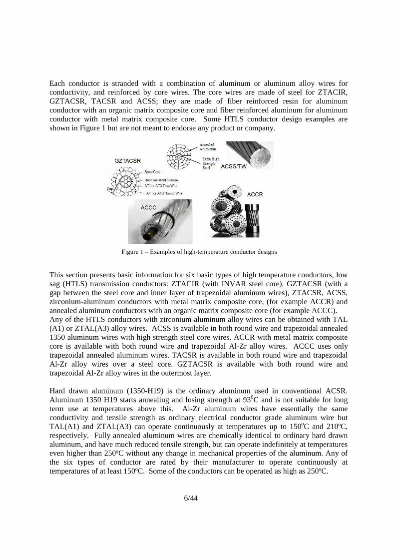
Each conductor is stranded with a combination of aluminum or aluminum alloy wires for conductivity, and reinforced by core wires. The core wires are made of steel for ZTACIR, GZTACSR, TACSR and ACSS; they are made of fiber reinforced resin for aluminum conductor with an organic matrix composite core and fiber reinforced aluminum for aluminum conductor with metal matrix composite core. Some HTLS conductor design examples are shown in Figure 1 but are not meant to endorse any product or company.
Figure 1 – Examples of high-temperature conductor designs
This section presents basic information for six basic types of high temperature conductors, low sag (HTLS) transmission conductors: ZTACIR (with INVAR steel core), GZTACSR (with a gap between the steel core and inner layer of trapezoidal aluminum wires), ZTACSR, ACSS, zirconium-aluminum conductors with metal matrix composite core, (for example ACCR) and annealed aluminum conductors with an organic matrix composite core (for example ACCC). Any of the HTLS conductors with zirconium-aluminum alloy wires can be obtained with TAL (A1) or ZTAL(A3) alloy wires. ACSS is available in both round wire and trapezoidal annealed 1350 aluminum wires with high strength steel core wires. ACCR with metal matrix composite core is available with both round wire and trapezoidal Al-Zr alloy wires. ACCC uses only trapezoidal annealed aluminum wires. TACSR is available in both round wire and trapezoidal Al-Zr alloy wires over a steel core. GZTACSR is available with both round wire and trapezoidal Al-Zr alloy wires in the outermost layer. Hard drawn aluminum (1350-H19) is the ordinary aluminum used in conventional ACSR. Aluminum 1350 H19 starts annealing and losing strength at 930C and is not suitable for long term use at temperatures above this. Al-Zr aluminum wires have essentially the same conductivity and tensile strength as ordinary electrical conductor grade aluminum wire but TAL(A1) and ZTAL(A3) can operate continuously at temperatures up to 150oC and 210ºC, respectively. Fully annealed aluminum wires are chemically identical to ordinary hard drawn aluminum, and have much reduced tensile strength, but can operate indefinitely at temperatures even higher than 250ºC without any change in mechanical properties of the aluminum. Any of the six types of conductor are rated by their manufacturer to operate continuously at temperatures of at least 150ºC. Some of the conductors can be operated as high as 250ºC.
7/44
Table 1 below summarizes the different classes of materials commonly or recently used in conductors. Iron-based strands Steel (Regular-, High-, Extra-high-, Ultra-high- strength) Coated Steel (galvanized, aluminum-clad, aluminum-5%mischmetal clad) Invar (typically Fe-Ni alloy – with coatings above) Aluminum Hard Drawn Pure Aluminum Annealed Pure Aluminum Heat-Resistant Aluminum (Aluminum-Zirconium Alloys). TAL (A1), ZTAL(A3) High Strength Aluminum Alloys (6201 etc) (Aluminum-Magnesium-Silicon Alloys) Aluminum composite (aluminum reinforced with fibers) Polymer Polymer matrix composites (resin with carbon fibers) Table 1. Constituent Materials used in HTLS Conductors.
3.0 Strand Evaluation
The constituent materials used in HTLS conductors vary dramatically as shown in Table 1. Some cores are common steel strands coated with zinc, zinc alloy, or aluminum. Other conductors utilize relatively new materials such as fiber reinforced aluminum composites or fiber reinforced polymer composites. The required tests and the test methods will differ depending on materials. All the strand materials used in the conductor should be fully evaluated before proceeding with the conductor evaluation. In many cases, basic performance issues and unsuitability of some materials is readily determined at the strand level thus avoiding costly conductor evaluation and field testing. The basic electrical, mechanical, chemical and thermal properties of the constituent strand materials should be evaluated before testing at the conductor level.
The basic material properties that control transmission line design are tensile strength, elastic modulus, density, coefficient of thermal expansion, conductivity and creep. Information on the aging (life-cycle) of the materials is important, justifying an evaluation of the response of the strands under the worst operating scenarios.
This section discusses and evaluates strand performance for overhead power transmission system applications. From this, important material attributes are identified. A basic description of test objectives, pass/fail criteria and test procedures are provided.
Some tests will naturally focus on one material of a non-homogenous conductor (typically the core strands). However it must be noted that the properties of one part of the conductor (core or outer) can affect the whole conductor due to interactions, so testing the whole conductor will always be important.
8/44
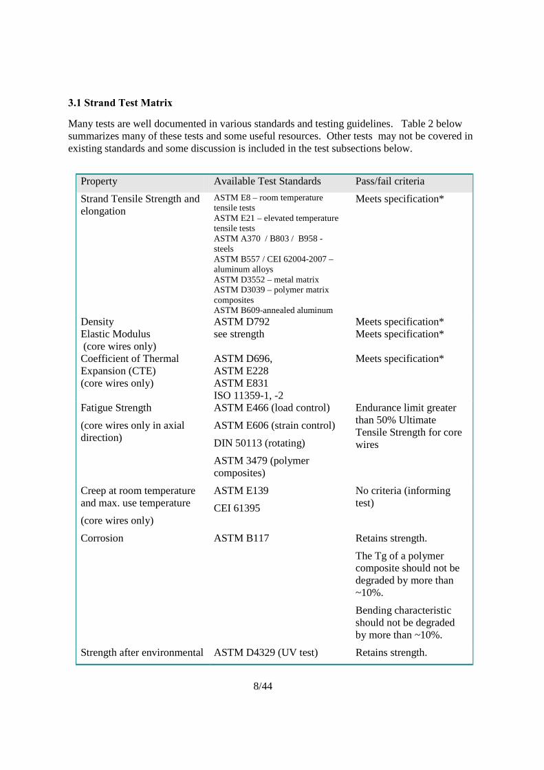
3.1 Strand Test Matrix
Many tests are well documented in various standards and testing guidelines. Table 2 below summarizes many of these tests and some useful resources. Other tests may not be covered in existing standards and some discussion is included in the test subsections below.
Property Available Test Standards Pass/fail criteria
Strand Tensile Strength and elongation
ASTM E8 – room temperature tensile tests ASTM E21 – elevated temperature tensile tests ASTM A370 / B803 / B958 - steels ASTM B557 / CEI 62004-2007 – aluminum alloys ASTM D3552 – metal matrix ASTM D3039 – polymer matrix composites ASTM B609-annealed aluminum
Meets specification*
Density ASTM D792 Meets specification* Elastic Modulus (core wires only)
see strength Meets specification*
Coefficient of Thermal Expansion (CTE) (core wires only)
ASTM D696, ASTM E228 ASTM E831 ISO 11359-1, -2
Meets specification*
Fatigue Strength
(core wires only in axial direction)
ASTM E466 (load control)
ASTM E606 (strain control)
DIN 50113 (rotating)
ASTM 3479 (polymer composites)
Endurance limit greater than 50% Ultimate Tensile Strength for core wires
Creep at room temperature and max. use temperature
(core wires only)
ASTM E139
CEI 61395
No criteria (informing test)
Corrosion ASTM B117 Retains strength.
The Tg of a polymer composite should not be degraded by more than ~10%.
Bending characteristic should not be degraded by more than ~10%.
Strength after environmental ASTM D4329 (UV test) Retains strength.
9/44
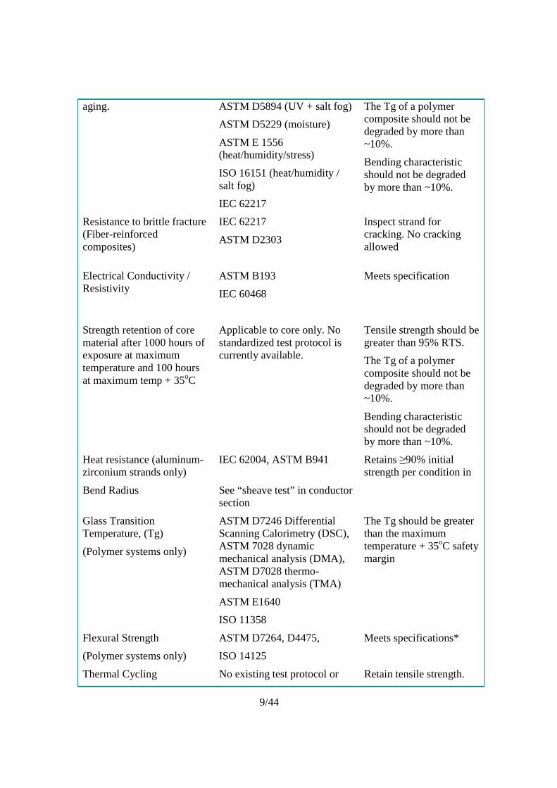
aging. ASTM D5894 (UV + salt fog)
ASTM D5229 (moisture)
ASTM E 1556 (heat/humidity/stress)
ISO 16151 (heat/humidity / salt fog)
IEC 62217
The Tg of a polymer composite should not be degraded by more than ~10%.
Bending characteristic should not be degraded by more than ~10%.
Resistance to brittle fracture (Fiber-reinforced composites)
IEC 62217
ASTM D2303
Inspect strand for cracking. No cracking allowed
Electrical Conductivity / Resistivity
ASTM B193
IEC 60468
Meets specification
Strength retention of core material after 1000 hours of exposure at maximum temperature and 100 hours at maximum temp + 35oC
Applicable to core only. No standardized test protocol is currently available.
Tensile strength should be greater than 95% RTS.
The Tg of a polymer composite should not be degraded by more than ~10%.
Bending characteristic should not be degraded by more than ~10%.
Heat resistance (aluminum-zirconium strands only)
IEC 62004, ASTM B941 Retains ≥90% initial strength per condition in
Bend Radius See “sheave test” in conductor section
Glass Transition Temperature, (Tg)
(Polymer systems only)
ASTM D7246 Differential Scanning Calorimetry (DSC), ASTM 7028 dynamic mechanical analysis (DMA), ASTM D7028 thermo-mechanical analysis (TMA)
ASTM E1640
ISO 11358
The Tg should be greater than the maximum temperature + 35oC safety margin
Flexural Strength
(Polymer systems only)
ASTM D7264, D4475,
ISO 14125
Meets specifications*
Thermal Cycling No existing test protocol or Retain tensile strength.
10/44
(Core wires only) standard The Tg of a polymer composite should not be degraded by more than ~10%.
Bending characteristic should not be degraded by more than ~10%.
Table 2. Tests for Evaluating HTLS Strands.
* If no standard exists, material has to respect manufacturer’s specification
3.2 Strand Tensile Strength, Elongation and Density
Design and Performance Issues
Strand tensile strength, density and elongation to failure are basic properties affecting line design tension and sag. They should be the first properties evaluated and compared to the manufacturer specifications. The strength should be measured at room temperature, low temperature (-30 C), and maximum operating temperature. The measured values should meet the manufacturer specifications.
Recommended Test Methods
Measuring the tensile strength of a material involves gripping two ends of a sample and pulling at a controlled rate until the material breaks or ruptures. For steels and aluminum alloys, the gripping and testing procedure is quite forgiving and accurate data is easily obtained. For metals, defined strain rates should be used as strength increases with increasing strain rates. With fiber reinforced composite materials there are additional requirements of specialized gripping and accurate alignment of the pulling grips in order to generate accurate data free from gripping and sample end effects. Density and elongation to failure are measured according to the standard tests listed in Table 2.
3.3 Strand Elastic Modulus
Design and Performance Issues
Stiffness is important to properly design and install conductors on overhead lines. High mechanical loads are typified by heavy ice and wind loading events, where a high elastic modulus results in minimal sag change. Conversely, low elastic modulus core materials can result in large amounts of sag under conditions of heavy mechanical load. The measured values should match the manufacturer specifications.
Recommended Test Method.
Measurement of the elastic modulus of a material follows the same experimental test set-up as the tensile strength, except that the sample strain is monitored (by strain gauge, extensometer). When stress and strain are reviewed against each other, there is usually a region of the data which exhibits a linear behavior. The slope of this region is typically used as the elastic modulus constant for the strand. For metals, the linear elastic modulus is usually below the
11/44
yield point of the material (often 0.2% strain for aluminum alloys). In some composite materials, the entire stress-strain data curve typically exhibits linear and elastic behavior.
3.4 Strand Thermal Elongation
Design and Performance Issues
The thermal elongation is defined by the coefficient of thermal expansion (CTE). The CTE models the conductor elongation with operating temperature. Typically for high temperature conductors, since the aluminum has a larger CTE than the core, the thermal elongation properties of the core control the maximum sag of the conductor. With heating, the aluminum will transfer its mechanical load to the core resulting in the core carrying most, if not all, of the mechanical load. The measured thermal elongation should meet the manufacturer’s specifications.
Recommended Test Methods
The thermal elongation is measured according to ASTM D696, ASTM E228, ASTM E381, or ISO 11359-1, -2
3.5 Strand Fatigue Performance
Design and Performance Issues
Fatigue resistance is important for enduring the adverse effects of aeolian vibration and galloping. Aeolian vibration is a low amplitude, high frequency process which directly relates to the high cycle fatigue resistance of the material. This phenomenon typically occurs in a range of 10-100 million cycles. Conversely, galloping is a high amplitude, low frequency event which relates to the low cycle fatigue resistance of the material. This phenomenon typically occurs in a range of 10-100 thousand cycles. Note that for conductors, the fatigue stress is actually an alternating bending stress, with the highest vibration amplitudes occurring in the outer layers of the conductor. Generally all materials lose strength with increasing fatigue cycles and strength loss is more rapid for increasing stress amplitudes. For common ferrous core materials and composites this is typically not a problem. Fatigue failures in conventional conductors are typically by fretting the aluminum layers at support locations (clamps, etc.) where the stresses concentrate due to the attachment hardware. The guideline is that the endurance limit for the core strands should equal or exceed 50% of the ultimate tensile strength. Testing at the conductor level in the suspension assembly is also needed to fully assess the vibration performance, see section 4.
Recommended Test Methods
Fatigue S-N (stress vs. number of cycles) curves should be generated at medium and high stresses according to ASTM E466 (load control), DIN 50113 (rotating), ASTM 3479 (polymer composites) test protocols.
3.6 Strand Creep
Design and Performance Issues
12/44
Creep is a time dependent permanent elongation of the conductor under a sustained mechanical load. Steel and fiber reinforced composite core strands typically have very low levels of creep, whereas aluminum and aluminum alloys typically exhibit a higher creep rate. It is important to validate that the creep rate in the core strand will stay within acceptable limits during use. A good reference value is to compare the creep rates with an ACSR or ACSS in the range of use temperature.
Recommended Test Method: ASTM E139 & CEI 61395
3.7 Strand Corrosion Resistance
Design and Performance Issues
To maintain adequate strength over the service life of the conductor, the conductor should exhibit good corrosion resistance to anticipated environmental corrosion processes. Steel cores typically use corrosion protection measures such as zinc (galvanized) coatings, aluminum cladding, or zinc- 5% aluminum-mischmetal coatings. Aluminum usually is the best material for use in typical corrosion environments as it exhibits good corrosion resistance to almost all corrosive environments. However, aluminium corrosion can occur in oxygen deficient cells below the upper strand layers in salt polluted environment. Coastal regions where humid salt atmospheres are found are more aggressive on most materials. Polluted environments such as industrial atmospheres can accelerate corrosion due to the acidic chemicals present.
In metal matrix composites, an additional corrosion concern requires evaluation. The possibility of galvanic (corrosion) coupling of the fiber and matrix constituents through contact with moisture may result in corrosion of the interfacial boundary between fiber and matrix. This should be evaluated. Additionally, any possible galvanic coupling between the core and the outer aluminum strands requires evaluation, as this process may accelerate deterioration.
Fiber reinforced polymer cores also require their own set of additional environmental evaluations. The issue of possible galvanic coupling between the fibers (particularly carbon fibers) and the outer aluminum strands also applies to these cores, this requiring corrosion testing. Aging of the polymer matrix due to exposure to the environment and its susceptibility to environmental conditions could reduce the structural integrity of the composite core, and potentially allow galvanic coupling between any exposed carbon fibers and the aluminum strands. Corrosion testing should be performed. It is therefore important to evaluate any changes in polymer properties during aging tests. This can be achieved by monitoring the flexural and compressive strength of the composite as well as the glass transition temperature (Tg) of the matrix. Undesirable aging of the matrix will manifest itself in significant fluctuation in one of those properties.
The tensile strand strength should not be degraded. In addition, polymer composites should be evaluated for changes in the glass transition temperature. The (Tg) drop should be less than 10% and any change in flexural and compressive strength should be less than 10%.
Recommended Test Methods
13/44
It is recommended to evaluate the corrosion resistance at the conductor level to fully evaluate the potential interaction between all the constituents, section 2. Corrosion tests are performed per ASTM B117.
3.8 Strand Environmental Aging (moisture, heat, UV)
Design and Performance Issues
This is a polymer aging issue and only applies to polymer constituents. Concerning polymer composite materials, it is important to evaluate aging under combined environmental conditions. Aging under one set of conditions can be very different than aging with multiple conditions combining exposure to heat, moisture, humidity and UV. Degradation of the polymer can be monitored by change in tensile and flexural strength, as well as a change in glass transition temperature “Tg.”
Recommended Test Methods
IEC 62217 was derived for testing polymer composite insulators, ASTM D4329 (UV test), ASTM D5894 (UV + salt fog), ASTM D5229 (moisture), ASTM E 1556 (heat/humidity/stress). Ideally, these would be combined into a single test using all of the environmental stress factors in combination.
3.9 Strand Brittle Fracture
Design and Performance Issues
This is a stress-corrosion phenomenon and applies mainly to glass reinforced polymer systems, although some susceptibility has been noted in carbon polymer systems. The evaluation examines the resistance of the material to a sustained stress in water or an acidic environment. For a transmission conductor, the source of the acid is either acid rain or acids generated from the interaction of electrical corona and humid air. Successful test methodologies have been developed for polymer insulators. The typical degradation process involves stress corrosion on the insulator surface which exposes surface fibers in the strength member and the increasing mechanical stresses with fiber loss accelerates fiber breakage leading to a sudden rupture of the strength member of the polymer insulator. The polymer composite strand should not exhibit any surface or internal cracking under combined stress and moisture.
Recommended Test Methods
Test should be performed according to ASTM D2303 or IEC 62217. IEEE document (Reference: M. Kuhl, FRP Rods for Brittle Fracture Resistant Composite Insulators, IEEE Transactions on Dielectrics and Electrical Insulators 2001, 8 (2), pp 182-190) may also be applied. At the end of the test, the sample is visually observed for damage and should retain 100% of its RTS with no degradation when subsequently pulled to failure.
3.10 Electrical Conductivity/Resistivity
Design and Performance Issues
14/44
This is typically a secondary concern for core materials, but a critical factor for the outer aluminum layers which provide the majority of the electrical conducting path. Fiber reinforced polymer composites are effectively insulators, precluding the need for a measurement.
Recommended Test Methods
ASTM B193 or IEC 60468
3.11 Resistance to Sustained High Temperature (core) and Heat Resistance, (aluminum)
Design and Performance Issues
It is important that all the materials (core and outer aluminum as well as any grease used) can resist high temperature exposure without appreciable changes in fundamental properties. Steel cores are typically limited by coating breakdown to either 200-250°C (galvanized) or 250-300°C (aluminum-clad and “zinc-5% aluminum-mischmetal alloy coated steel wire) due to reaction and breakdown of the protection layers. Temperature excursions arise from two sources. Firstly, by increasing the current, the temperature increases due to resistive heating. Secondly, during a fault current situation, very high currents run through the lines for up to two seconds until the circuit breakers open. During this time, the temperature increases very rapidly and can seriously degrade the strength if the temperature goes too high. Thus aging curves or predictor equations of the material need to be developed showing strength change versus time for various temperatures and durations of exposure.
Temperatures to be considered need to include the highest emergency operating temperature specified by the manufacturer for the conductor and for a temperature that is at least 35°C above this to investigate reliability to accidental overheating (zero wind condition, network overload, short-circuit condition, conductor thermal gradient).
Typically operators take into account a margin between maximum allowable temperature of the material and maximum operating temperature of the conductor. This margin should consider:
- temperature gradients along the conductor length and in the radial direction which can frequently exceed 15 – 30°C [25]
- New conductors have initially a lower emissivity that can lead to a 15°C rise over the rated temperature [25]
- In addition, with the weather parameters used for line rating there is a probability (typically less than 2%) that the conductor temperature will exceed the rated temperature by 15°C.
The tensile strength should not be reduced by more than ~5% over the initial rated strength. The strand coating (i.e., galvanic coating for steel) should not exhibit any cracking or flaking. In a polymer or metal matrix composite, the tensile and flexural strengths should also be evaluated after temperature exposure and not be degraded by more than 10% over the initial value. The glass transition temperature should not be degraded by more than 10 % over the initial value. The heat resistance of high temperature aluminum alloys should follow IEC standard 62004.
15/44
Recommended Test Methods
For all core materials, measure the tensile strength after 1 hr, 10 hrs, 100 hrs, and 1000 hrs (and more if required) at the maximum rated “emergency” core temperature (As discussed in section 3.13, the “emergency” core temperature should be at least 35oC higher than the normally specified conductor surface temperature to allow for radial temperature and axial temperature uncertainties over the life of the conductor). For polymer composites measure the tensile strength, flexure strength and Tg. The strand coating (i.e., galvanic coating for steel) should not exhibit any cracking or flaking. The (Tg) drop should be less than 10% and any change in flexural should be less than 10%. All core materials should retain ~95% of their RTS after exposure. Temperature resistant aluminum strands should be evaluated according to IEC 62004.
3.12 Bend Radius
Design and Performance Issues
Composite materials have a more limited ability to conform to a bend radius than conventional engineering metals and alloys such as steel and aluminum since they have a limited strain to failure and have no plasticity. Thus care needs to be taken in choosing the correct diameter installation sheaves (i.e. travellers), bullwheel-tensioners, and conductor reels, to prevent failure or overstressing. In addition, the conductors conform to a bend as they pass through a suspension clamp at a tower. Tensile stresses typically build up on the outer edge of a bend radius. In metal matrix composites the compression strength may be higher than the tensile strength. So the bend radius is limited by the tensile strength and strain. However, in unidirectional polymer composites the opposite may be true, where the tensile strength is typically much greater than the compressive strength. Therefore, the limiting bending case with a uni-directional polymer composite is typically on the compression face of the bend radius. The minimum bend radius must not exceed the manufacturer’s specifications.
Recommended Test Methods
The bend radius should be evaluated at the conductor level with an appropriate sheave test at different tension levels. The core wires should then be inspected for any sign of damage or cracking.
3.13 Glass Transition Temperature of Polymer Composites
Design Consideration
In a polymer (thermo-set) composite, the Tg is defined as the knee point of the curve in which the polymer matrix (resin system) begins to soften or change from a harder “glassy” state to a softer “rubbery” state. As the temperature approaches - or exceeds the Tg - the ability of the matrix to transfer loads between the load-bearing fibers decreases; As the temperature of the conductor subsequently cools, the ability of the resin to transfer loads between the load-bearing fibers returns. However, should the temperature of the conductor significantly exceed the Tg for extended periods of time, accelerated aging will occur and a reduction in ultimate strength can be expected. Therefore Tg is an interesting characteristic to measure in order to assess polymer aging. An initial test is required and results should be compared with Tg measurements after aging tests.
16/44
There is a finite probability that the actual core temperature will exceed the rated temperature over its lifetime. For example, temperature gradients along the conductor length and in the radial direction can frequently exceed 15 - 300C [25]. New conductors have initially a lower emissivity that can lead to a 150C rise over the rated temperature, [25]. In addition, with the weather parameters used for line rating there is a probability (typically less than 2%) that the conductor temperature will exceed the rated temperature by 150C.
The polymer should be monitored during the aging test to ensure that changes in polymer bonds due to moisture or other aging effects do not largely affect the Tg or otherwise degrade the conductor’s strength which could compromise the conductor’s integrity or reduce its service life. The Tg should not be degraded by more than 10% after various and/or combined accelerated thermal and environmental aging.
Recommended Test Methods
The Tg can be measured by Differential Scanning Calorimetry (DSC), Dynamic Mechanical Analysis (DMA), or Thermo-Mechanical Analysis (TMA). Once the method is chosen, it should be used consistently to ensure that any comparative values are based on the same measurement technique. Test sample preparation must also be accomplished in a uniform and consistent manner.
3.14 Flexural Strength of Polymer Composites
Design and Performance Issues
The flexural strength in polymer composites is governed in part by the matrix properties. The flexural strength of metals and metal matrix composites is directly related to the tensile strength therefore flexural strength evaluation in addition to tensile strength is not necessary for this class of materials. Degradation of the flexural strength after thermo-mechanical or environmental exposure is a good indicator of aging issues, similar to the glass transition temperature. In polymer composites, the initial bending characteristics should be compared with final characteristics measured after any aging test.
The flexural strength of polymer composite strand should not degrade by more than ~10% after thermal or environmental exposure. ~10 % is a recommended guideline based on aerospace and military standards.
Recommended Test Methods
ASTM D7264, ASTM D4475, or ISO 14125. Bending characteristics can be assessed with 3 or 4 points bending tests. The test setups and sample lengths vary between the various test protocols. Typically at least five samples are tested and an average value is used for comparison. Once the method is chosen, it has to be preserved for the entire test.
3.15 Strand Thermal Cycling
Design and Performance Issues
Thermal cycling is the alternating heating and cooling of a material. For monolithic materials like metals (steel and aluminum), there is little concern in regard to thermal fatigue from this
17/44
cycling. In fiber reinforced composite materials, there are two or more different materials present, each with a different coefficient of thermal expansion behavior, so thermal cycling induces alternating stress state. This may lead to void growth in some metal matrix composite systems, and to de-lamination damage, matrix aging or cracking in polymer matrix composite systems, all of which can lead to strength loss. The magnitude of the damage depends on the materials chosen and the duration and extent of the exposures, but the larger the difference in thermal expansion coefficient between the constituent materials and the larger the temperature excursion of the cycle, the greater the cycling thermal stresses become.
In metallic materials the tensile strength should not degrade by more than 5% after cycling. The strand coating (i.e., galvanic coating for steel) should not exhibit any cracking or flaking. For polymer composites the tensile strength and flexural strength should not degrade by more than 10%. The Tg should not change by more than 10% .
Recommended Test Methods
Cycle the individual strands between room temperature and maximum use temperature for 1000, 10000 and 100,000 cycles and measure the retained tensile strength. The (Tg) drop should be less than 10% and any change in flexural should be less than 10%. The retained strength should be preserved.
4. Conductor Evaluation
4.1 Class of Conductor Constructions
High temperature conductors and accessories must be designed to operate reliably in demanding conditions that combine high temperature operation under a broad spectrum of mechanical and electrical loads.
Chemical and environmental stability is essential, along with retention of mechanical and electrical properties over the life of the conductor. In addition, the conductor and accessories must resist a wide range of transient mechanical and thermal loads such as fault currents, lightning strikes, galloping events, and ice loading. Any new materials or designs should be methodically tested to evaluate their life cycle performance. Comprehensive testing also needs to include the terminations and other accessories; this is particularly important when the operating temperatures and performance are pushed to new limits.
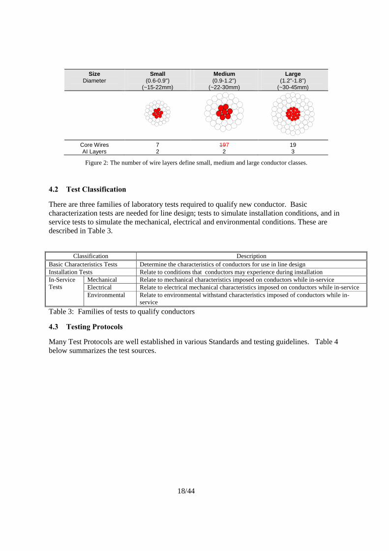
While at first glance conductors seem to be a simple combination of core and aluminum strands they are in fact a family of conductors where each differs by diameter, number of layers, shape of the strands, and the area fraction of the core relative to the overall cross sectional area. While it is not necessary to test all conductor constructions, a central foundation of data must be generated. It is necessary to manufacture, test, characterize, and demonstrate in field trials a critical subset of conductors. Thereafter extrapolation to other conductor diameters may be made, within the size and type class, with only the addition of limited performance data.
18/44
Size Diameter
Small (0.6-0.9")
(~15-22mm)
Medium (0.9-1.2")
(~22-30mm)
Large (1.2"-1.8")
(~30-45mm)
Core Wires AI Layers
7 2
197 2
19 3
Figure 2: The number of wire layers define small, medium and large conductor classes.
4.2 Test Classification
There are three families of laboratory tests required to qualify new conductor. Basic characterization tests are needed for line design; tests to simulate installation conditions, and in service tests to simulate the mechanical, electrical and environmental conditions. These are described in Table 3.
Classification Description Basic Characteristics Tests Determine the characteristics of conductors for use in line design Installation Tests Relate to conditions that conductors may experience during installation In-Service Tests
Mechanical Relate to mechanical characteristics imposed on conductors while in-service Electrical Relate to electrical mechanical characteristics imposed on conductors while in-service Environmental Relate to environmental withstand characteristics imposed of conductors while in-
service
Table 3: Families of tests to qualify conductors
4.3 Testing Protocols
Many Test Protocols are well established in various Standards and testing guidelines. Table 4 below summarizes the test sources.
19/44
Test Standards Modifications Pass/Fail criteria Basic
Breaking Strength –Epoxy Ends
ANSI C119.4 section 7.3.4, IEC 61284 section 11.5.1
None Meets strength specification
Stress-strain Curves – Epoxy Ends
Aluminum Association Guideline, IEC 61089 Annex B
None Test and record: derive polynomial coefficients
Electrical Resistance ASTM B193 IEC 60468
none Meets DC resistance specification
Creep (20°C) Aluminum Association Guideline, IEC 61395.
None Verify that creep of new conductor is less or equivalent than ACSR creep for conductor of same size and type. Derive creep rate equations and creep stress-strain equations.
Thermal Expansion none Meets specification Installation Sheave Test IEEE 1138 Annex D,
IEC 60794-1-2 section 20
See section 4.9 Conductor and core strands should remain undamaged after sheave test
Radial Crush EIA/TIA 455-41, IEC 60794-1-2 section 7
See section 4.10 Document outer strand damage, core strands should remain undamaged.
Torsional Ductility IEC 60794-1-2 section 11
Look for aluminum to be first to fail constituent under repeated increasing rotations
Aluminum must fail first, core strength >95% RBS after torsional failure of aluminum layers
In Service
Sag-temperature none Section 4.12 Validate sag up to maximum temperature. No reduction in strength after sag test.
Aeolian Vibration IEEE 1138 Annex B, IEC 60794-1-2 section 21
None Verify that conductor is undamaged after 100 million cycles Conductor should retain ~95% RTS
Galloping IEEE 1138 Annex C 8% RBS Verify that conductor is undamaged after 100,000 cycles
Corrosion ISO 9227:1990 standard / ASTM B117 / IEC 62217
None Measure weight loss. Conductor strands should meet strength specification. Tg should not degrade by more than ~10%. Polymer tensile and flexural strength. should not degrade by more than ~10%.
Fault Current IEEE 1138 Annex A5, IEC 60794-1-2 section 37
Increase fault, measure temperatures, look for onset of birdcaging.
Verify that conductor can accept fault currents equivalent to ACSR without damage
Temperature Cycle none Section 4.17 Verify that conductor retains ~95% of RTS strength
Cold Temperature Test
none Section 4.18 Full strength at low temperature
Conductor Grease IEC 61304 Does not dry or crack at high temperature
Table 4. Conductor Qualification
20/44
4.4 Conductor Strength
Design and Performance Issues
Conductor strength and weight directly impacts the amount of sag (D) and tension (H) in a overhead transmission conductor. Specifically,
D= w*S2/(8*H) Eq 1
where; S=span length w= weight per unit length
Thus (H/w) is directly related to specific tensile strength. Generally the higher the specific tensile strength, the lower the sag.
The conductor should meet the specified strength.
Recommended Test Method.
The purpose is the verification that the actual (ultimate) tensile strength of the conductor meets or exceeds the rated breaking tensile strength (RBS) specified by the supplier. Test methods may follow ANSI C119.4 section 7.3.4, and/or IEC 61284 section 11.5.1.
The test for metal matrix composites and polymer composites should follow the manufacturer’s recommendation for testing procedures, in particular gripping of the core and conductor.
4.5 Stress-strain response
Design and Performance Issues
The purpose of this test is to define the stress strain curve of the conductor. This curve allows designers to compute sag of the conductor. The measured stress-strain curve should be used to derive the polynomial coefficients. Recommended Test Methods
Test procedures are described in Aluminum Association Guide, Rev. 1999, “A Method of Stress-Strain Testing of Aluminum Conductors and ACSR and A Test Method for Determining the Long Time Creep of Aluminum Conductors in Overhead Lines”, and in IEC 61089 Annex B.
4.6 Electrical Resistance
Design and Performance Issues
Electric losses on the grid are mainly due to the electrical resistance. DC resistance at a specific temperature depends on aluminum area and its grade. This electrical resistance increases with the temperature.
21/44
The measured resistance should be less than or equal to the specified value. Recommended Test Methods
The DC electrical resistance and thus resistivity of the conductor will be measured and compared to the calculation derived from constituent properties. ASTM B193 & IEC 60468 provides a standard on measuring electrical resistance and resistivity.
4.7 Creep
Design and Performance Issues
The creep of conductors becomes important due to the inelastic nature of metal under everyday tensions over many years of operation. Typically the aluminum creeps and the sag permanently increases. Predictive knowledge of this increase becomes part of the design criteria for loading design conditions, since allowance is made for sag due to creep.
The creep should be compared to that of an equivalent size AAAC, ACSR, or other familiar conductor, with the creep of the new conductor being equivalent or less than familiar conductor creep. If the creep is notably different than a familiar conductor, it may be wise to pay additional attention to the sag after 10 year creep.
In addition, creep at high temperature (maximum operating temperature) should be measured to check that it is similar to room temperature creep. For simplicity, the core only may be measured at high temperature since almost the entire conductor load is typically carried by the core at these temperatures. The data generated at high temperature is not typically used in transmission design.
Recommended Test Methods
Aluminum Association Guide, Rev. 1999, “A Method of Stress-Strain Testing of Aluminum Conductors and ACSR and A Test Method for Determining the Long Time Creep of Aluminum Conductors in Overhead Lines” or IEC 61395 with modification to add creep measurements at the maximum use temperature under expected service loads. The conductor load at high temperature will typically be significantly lower than at room temperature due to thermal elongation. This behavior needs to be validated before selecting the load values for the creep tests at elevated temperature.
4.8 Conductor Thermal Expansion
Design and Performance Issues
The thermal expansion is needed to predict sag versus temperature. In non-homogeneous conductors, two regimes are defined in a plot of strain vs temperature, namely above and below a kneepoint (point where aluminum unloads). The slope of the line in these two regions is the rate of change of strain with temperature, which is the coefficient of thermal expansion (CTE). Two CTE’s will be measured, one above and one below the knee-point temperature.
The measured values should match the specified value.
Conductor Thermal Expansion: Recommended Test Methods
22/44
There is no test standard. A suggested procedure is as follows:
Terminate a conductor with resin ends. Place in a tensile testing frame with provision to monitor strain (strain gauges, extensometer). Pretension at a mechanical tension below yield point of aluminum (in order to avoid to have a knee point below room temperature) for a few hours to minimize creep and allow strand settling. Reset load to 10-20 % RBS and maintain throughout the test. The level of load chosen moves the position of the kneepoint. Thus a test at 10% RBS may have a kneepoint at a low temperature which creates a larger set of data above the kneepoint from which to evaluate the thermal expansion. Conversely, a higher load may have a kneepoint at a higher temperature which creates a larger set of data below the knee-point temperature from which to evaluate the thermal expansion.
Heat the conductor (e.g. via current). Heat slowly from 20°C to 50°C while measuring the strain change, and then hold at 50°C for 30 minutes and continue to measure strain. This is to stabilize the temperature. Then continue increasing the temperature slowly in 50°C increments followed by stabilization for 30 minutes. Proceed until the maximum temperature is reached. Follow the same procedure during cooling. At the end of the test, note any change in strain from the starting condition.
Plot the %strain vs temperature. Identify the two regimes above and below the knee-point temperature. Calculate the slopes in each regime. These may be done in two ways, one with a linear fit to the data that will represent an average CTE for that temperature range, and a second that would be second order (or higher) polynomial. This latter equation can then be differentiated with respect to temperature to give what is called the instantaneous CTE at a given temperature. CTE could then be plotted against temperature.
4.9 Sheave Test
Design and Performance Issues
Installation can lead to severe loading conditions. A sheave test is necessary to ensure that the conductor is not damaged during the stringing operation. The amount of stress imparted in the strands during stringing will be a function of the conductor size, strand diameter, materials, sheave geometry (diameter and groove size), angle over the sheave, applied tension and number of passes.
Composites are highly anisotropic, i.e, they have good tensile strength but lower shear, transverse and torsional strength. Their response under multi-axial stresses needs to be carefully evaluated under installation conditions. The selection of sheave diameter and groove radius will affect bending and crushing stresses. Some conductor grips can also damage composite cores under combined loading. Conductor pulling can induce torsional loading.
The sheave test is designed to show the conductor is robust for installation over stringing sheaves (pulleys), where it has to conform to the bend radius of the sheave. Indeed the conductor passes over multiple sheaves in a multi-span installation so bending fatigue and combined bending-tension loads are applied.
The sheave test has to demonstrate that the conductor remains undamaged after being subjected to multiple passes at selected tension levels and angles over the recommended sheaves. The core should be inspected and not damaged.
23/44
Recommended Test Methods
Standards IEEE 1138 Annex D and IEC 0794-1-2 section 20 may be adapted as a test to show robustness to this operation. The conductor is fixed at both ends, and then tension is applied with the conductor over a sheave (of suitable diameter) and at a desired angle. The sheave is then moved back and forth over the conductor or the conductor is moved over the sheave a specified number of times to simulate the conductor passing over the sheave. After this, the conductor is evaluated either by disassembly to constituent strands and inspection, or by a residual tension test.
4.10. Radial Crush
Design and Performance Issues
The intent of the Crush Test is to subject the high temperature conductor to simulated crushing or clamping forces that could occur during installation or maintenance (e.g. truck driving over the conductor). The conductor could be crushed to the extent of adversely affecting the tensile strength of the conductor. The core strands should remain undamaged after the crush test.
Recommended Test Methods
EIA/TIA 455-41 or IEC 60794-1-2 section 7 may be adapted as a test to show robustness to this operation. A short length of a sample is subject to a side crushing between two steel platens. The conductor is then stripped of aluminum wires and then the core wires tensile tested for residual strength. The core should retain its full strength. The damage (flattening, denting) of the outer aluminum strands is also noted.
4.11 Torsional Ductility
Design and Performance Issues
This is a test which provides insight into the ability of the conductor to withstand the torsional forces during installation. (i.e. stringing and sagging). The conductor and core should not be damaged.
Recommended Test Methods
IEC 60794-1-2 gives a test set-up to follow, but it is suggested this be extended. The conductor shall be tensioned to 20% of the conductor RBS. The conductor sample is rotated in the direction of the lay of the strands for one-half turn (180°). The conductor is then rotated one-half turn (180°) in the reverse direction to the lay of the strands. This constitutes one torsion cycle. This cycle is repeated a many times but with the rotation increasing by an extra one-half turn (180°) in each cycle (i.e. to 180°, 360°, 540°, 720°, 900° and so on). This continues until either the core or aluminum strands begin to break. This point is noted and then twist per unit length is calculated and reported. If the core is intact, the aluminum layers are stripped off and the core is tensile tested to failure and zero twist. The strength compared to the initial strength of the core is reported.
24/44
4.12 Sag and Temperature Performance
Design and Performance Issues
Validation of sag versus temperature is performed on a controlled test span. The test validates the sag-tension response over time and most importantly sag at elevated temperatures.
With this test it is possible to define the aluminum compression value used in design and check the thermal expansion. Different overload cycles may be applied and the conductor will withstand combined thermo-mechanical cycles and thus the test simulates multiple emergency conditions.
The measured tension and sag should match the predicted values at the maximum operating temperature. The tension and sag should remain predictable after multiple emergency cycles. The conductor strength should not be degraded after multiple thermal cycles. For polymer composites, additional validation is recommended to ensure that the flexural strengths have not degraded by more than 10% and the Tg has not changed by more than 10% .
Recommended Test Methods
There is no specific standard for this test. This is one example of a protocol (this test can be carried out in laboratory or on an outdoor span).
Heat the conductor from room temperature to the maximum operating temperature and back. Continuously measure the sag, tension, and temperature.
In outdoor: This test could be done during at least 2 weeks in 2 different periods of the year. For instance winter and summer seasons:
� During the weekend and the night, conductor is maintained at the maximum permanent temperature.
� Simulate about 10-1000 cycles between ambient temperature and maximum operating temperature. Time to reach the maximum operating temperature can be changed between the different tests in order to apply different current.
After the test: Check that the sag has not changed before and after the overload. Validate that the conductor retained at least 95% RBS. In addition for polymer core conductor, additional Tg and flexure tests can be performed.
4.13 Aeolian Vibration
Design and Performance Issues
Conductor and hardware must be designed to survive aeolian vibrations due to wind. Fatigue damage shall not occur on the metal components of the conductor or hardware at attachment locations. The purpose of this test is the verification of the mechanical integrity of the conductor and the supporting hardware when subjected to simulated vibration conditions.
The conductor should not exhibit any damage (broken strands, excessive fretting) and optionally be tested to demonstrate the conductor retains at least 95% RBS after 108 cycles.
Recommended Test Methods
25/44
IEEE 1138 Annex B or IEC 60794-1-2 section 21
An amplitude of one-third the conductor diameter under a tension of 25% RBS is suggested, with a break-over angle of 1-2°.
4.14 Ice Galloping
Design and Performance Issues
Conductor and hardware must be designed to survive ice galloping. This phenomenon can occur in areas that experience the combination of strong sustained winds and icing or wet snow formation on overhead line conductors. Fatigue or other damage shall not occur on the components of the conductor or hardware.
The conductor and suspension should be inspected and show no sign of damage after 100,000 cycles. The conductor strength may optionally be tested and should be least 95% RBS.
Recommended Test Methods
The intent of the Galloping Test is to subject the conductor and supporting hardware to high amplitude galloping motions per IEEE 1138 Annex C.
4.15 Corrosion
Design and Performance Issues
The objective of this test is to determine the effects of a controlled salt atmosphere on the conductor sample. A salt atmosphere is considered typically the most corrosive environment the conductor will experience, however, if more corrosive environments are anticipated, then appropriate tests within those simulated environments should be considered.
The conductor weight should be monitored, and any weight loss is an indicator of susceptibility to corrosion. Individual constituent strands from the conductor should meet their minimum strength specification after the test. For polymer composites the flexural and compressive strength should not drop by more than 10% and the Tg should not drop by more than 10%.
Recommended Test Methods
The test conductor samples are placed into a standard salt spray-testing box as defined by the ISO 9227:2006 standard or ASTM B117. Corrosion testing is an accelerated test that usually involves the use of an environmental chamber that delivers an environmental media at a controlled temperature and pH. A salt fog (salt spray) is the most common media although more aggressive environments that simulate polluted industrial environments are possible. Multiple test samples are placed in the chamber and progressively removed after increasing time increments up to 1000-2000 hours. The samples are cleaned and weighed to track weight loss due to corrosion, and then retained tensile strength of individual strands is measured to track critical property changes that may occur over time and exposure. A common test is to cycle salt fog, clean fog and dry periods as specified in IEC 62217 Annex C.
26/44
4.16 Fault Current Performance
Design and Performance Issues
Short circuits should not damage the integrity nor impair the functionality of any component of the conductor including its electrical, thermal, and mechanical performance. Fault current conditions can lead to transient temperatures in excess of 300°C causing permanent bird caging and possibly irreversible degradation of the core and/or the aluminum.
Fault current can be a result of a phase-to-tower or phase-to-phase short circuit. The end user will provide i) a description of short circuit fault current adequate for establishing the required I2t (I=current, t=time) requirement of the conductor, or ii) I2t as specified by the end user. Fault currents are large currents applied for very short times (0.2 to 2 sec commonly) before a circuit breaker eliminates the current. In this time, the temperature may rise rapidly and the conductor is subject to severe stresses.
The onset of bird caging will also be dependent on the materials. Conductors with a non-conductive core and low thermal expansion will exhibit a high temperature gradient and high differential elongation between the aluminum strand and the core. This can lead to permanent or temporary birdcaging at low short circuit levels.
The conductor and fittings should be inspected and show no sign of damage or permanent birdcaging at the specified short circuit level given by the user.
Recommended Test Methods
Standards IEEE 1138 section A5 and IEC 60794-1-2 section 37 may be adapted as templates to show robustness to fault currents. The conductor is tensioned to a predetermined load (10-25% RBS) and then current pulses are applied to the maximum conductor rating, with cooling to the initial temperature in between and constant temperature monitoring is used. Current pulses may be varied between short high current and long low current pulses depending on the target value of I2t desired. Thereafter, an optional residual tension test may be performed, or the conductor and fittings may be disassembled and inspected to look for signs of excessive wear, discoloration or other signs of breakdown. The conductor sample shall be visually inspected for birdcaging or other damage periodically throughout the test.
4.17 Temperature Cycle
Design and Performance Issues
The purpose of this test is verification of the degradation characteristic of metallic and non-metallic material when subjected to thermal cycling. Temperature cycling can create large internal stresses due to thermal expansion mismatch between constituents. For example: between the core wire and its protective coating, or between fibers and a matrix.
The conductor should retain at least 95% RBS after a minimum of 500 thermal cycles. In addition the wire should be inspected and show no sign of cracking or coating damage after thermal cycling. In polymer composites, the flexural strength should not degrade by more than 10% and the Tg should not degrade by more than 10% after thermal cycling.
27/44
Recommended Test Methods
A recommended thermal cycling test (combined cycling) is as follow:
- Mechanical tension, 20% RBS, marks on the conductor at the edge of the connector
- 100 cycles from room temperature up to maximum temperature specified by conductor manufacturer. Hold at maximum temperature +/- 2.5 o C for at least 5 min.
- Increase mechanical tension up to ~70% RBS at room temperature during and hold for 24 Hours. After 24 hours hold, release tension back to ~20% RBS
This cycling test will be repeated 5 times.
During the test, temperature of connectors, conductor and electrical resistance are recorded according to ANSI C 119.4 (Note this test can be carried out with epoxy or manufacturer recommended dead ends)
A breaking load test is applied at the end of the test. Conductor strength has to be higher than 95 % RBS.
Concerning polymer core conductor, it is recommended to make an Tg and bending tests on initial and aged conductor. The maximum test temperature have to be defined by manufacturer. At the end of the test the Tg and bending test will be performed. Final and initial values will be compared. The (Tg) drop should be less than 10 % and any change in flexural should be less than 10%.
4.18 Cold Temperature Test
Design and Performance Issues
Extreme cold can irreversibly affect composite conductors with large differentials in coefficient of thermal expansion by shedding excess load to the aluminum.
The conductor and fitting should reach at least 95% RBS at low temperature and not show any signs of damage. The conductor should not exhibit any sign of damage such as loose strands after the conductor has been subjected to cold temperature.
Recommended Test Methods
Load a section of conductor with a fitting to 20% RBS. Cool the conductor and fitting to -30 C and hold at temperature for at least one hour. Pull the conductor to failure at ambient temperature.
28/44
4.19 Conductor Grease
Design and Performance Issues
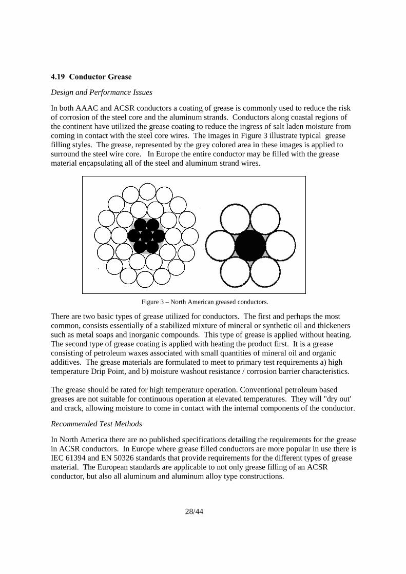
In both AAAC and ACSR conductors a coating of grease is commonly used to reduce the risk of corrosion of the steel core and the aluminum strands. Conductors along coastal regions of the continent have utilized the grease coating to reduce the ingress of salt laden moisture from coming in contact with the steel core wires. The images in Figure 3 illustrate typical grease filling styles. The grease, represented by the grey colored area in these images is applied to surround the steel wire core. In Europe the entire conductor may be filled with the grease material encapsulating all of the steel and aluminum strand wires.
Figure 3 – North American greased conductors.
There are two basic types of grease utilized for conductors. The first and perhaps the most common, consists essentially of a stabilized mixture of mineral or synthetic oil and thickeners such as metal soaps and inorganic compounds. This type of grease is applied without heating. The second type of grease coating is applied with heating the product first. It is a grease consisting of petroleum waxes associated with small quantities of mineral oil and organic additives. The grease materials are formulated to meet to primary test requirements a) high temperature Drip Point, and b) moisture washout resistance / corrosion barrier characteristics. The grease should be rated for high temperature operation. Conventional petroleum based greases are not suitable for continuous operation at elevated temperatures. They will "dry out' and crack, allowing moisture to come in contact with the internal components of the conductor.
Recommended Test Methods
In North America there are no published specifications detailing the requirements for the grease in ACSR conductors. In Europe where grease filled conductors are more popular in use there is IEC 61394 and EN 50326 standards that provide requirements for the different types of grease material. The European standards are applicable to not only grease filling of an ACSR conductor, but also all aluminum and aluminum alloy type constructions.
29/44
5.0 Accessory Evaluation
Suspension and dead-end hardware, some types of vibration damper hardware, spacers, and repair hardware for HTLS conductors are usually designed for a specific size and/or type of HTLS conductor. Hardware is generally not designed to accommodate a range of sizes of conductor. The hardware for HTLS conductor is commonly designed to keep the fitting cool when the conductor is running at high temperature. Also the materials should be selected to resist annealing or adverse aging in the expected range of operating temperature.
Factors that may influence the interaction of the hardware to HTLS conductor interfaces are as follows:
a) The materials chosen for the hardware should have material properties that are thermally stable for the operating temperatures
b) The accessory design should attempt to minimize the operating temperature experienced by the hardware.
c) The accessory should be designed and tested to ensure that the conductor retain its full performance with the accessories under normal and emergency loading conditions. This is particularly important when using new materials.
d) Contact between dissimilar materials may cause excessive corrosion in some environments. It is therefore recommended that hardware and other accessories connected electrically and mechanically to the conductor are compatible for the conductor being used.
30/44
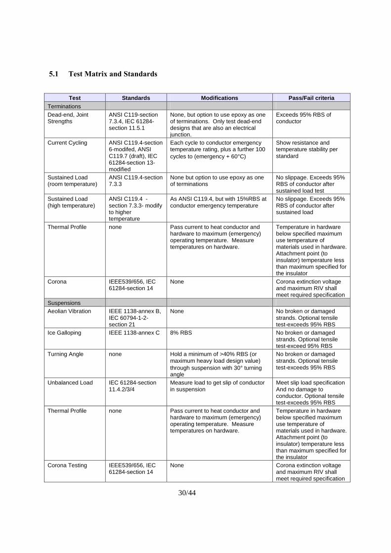
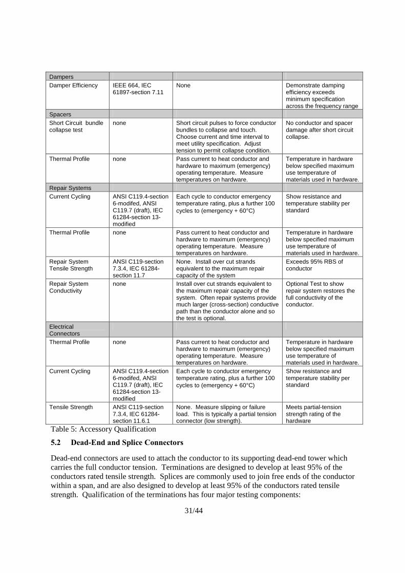
5.1 Test Matrix and Standards
Test Standards Modifications Pass/Fail criteria
Terminations Dead-end, Joint Strengths
ANSI C119-section 7.3.4, IEC 61284-section 11.5.1
None, but option to use epoxy as one of terminations. Only test dead-end designs that are also an electrical junction.
Exceeds 95% RBS of conductor
Current Cycling ANSI C119.4-section 6-modifed, ANSI C119.7 (draft), IEC 61284-section 13-modified
Each cycle to conductor emergency temperature rating, plus a further 100 cycles to (emergency + 60°C)
Show resistance and temperature stability per standard
Sustained Load (room temperature)
ANSI C119.4-section 7.3.3
None but option to use epoxy as one of terminations
No slippage. Exceeds 95% RBS of conductor after sustained load test
Sustained Load (high temperature)
ANSI C119.4 -section 7.3.3- modify to higher temperature
As ANSI C119.4, but with 15%RBS at conductor emergency temperature
No slippage. Exceeds 95% RBS of conductor after sustained load
Thermal Profile none Pass current to heat conductor and hardware to maximum (emergency) operating temperature. Measure temperatures on hardware.
Temperature in hardware below specified maximum use temperature of materials used in hardware. Attachment point (to insulator) temperature less than maximum specified for the insulator
Corona IEEE539/656, IEC 61284-section 14
None Corona extinction voltage and maximum RIV shall meet required specification
Suspensions Aeolian Vibration IEEE 1138-annex B,
IEC 60794-1-2-section 21
None No broken or damaged strands. Optional tensile test-exceeds 95% RBS
Ice Galloping IEEE 1138-annex C 8% RBS No broken or damaged strands. Optional tensile test-exceed 95% RBS
Turning Angle none Hold a minimum of >40% RBS (or maximum heavy load design value) through suspension with 30° turning angle
No broken or damaged strands. Optional tensile test-exceeds 95% RBS
Unbalanced Load IEC 61284-section 11.4.2/3/4
Measure load to get slip of conductor in suspension
Meet slip load specification And no damage to conductor. Optional tensile test-exceeds 95% RBS
Thermal Profile none Pass current to heat conductor and hardware to maximum (emergency) operating temperature. Measure temperatures on hardware.
Temperature in hardware below specified maximum use temperature of materials used in hardware. Attachment point (to insulator) temperature less than maximum specified for the insulator
Corona Testing IEEE539/656, IEC 61284-section 14
None Corona extinction voltage and maximum RIV shall meet required specification
31/44
Dampers Damper Efficiency IEEE 664, IEC
61897-section 7.11 None Demonstrate damping
efficiency exceeds minimum specification across the frequency range
Spacers Short Circuit bundle collapse test
none Short circuit pulses to force conductor bundles to collapse and touch. Choose current and time interval to meet utility specification. Adjust tension to permit collapse condition.
No conductor and spacer damage after short circuit collapse.
Thermal Profile none Pass current to heat conductor and hardware to maximum (emergency) operating temperature. Measure temperatures on hardware.
Temperature in hardware below specified maximum use temperature of materials used in hardware.
Repair Systems Current Cycling ANSI C119.4-section
6-modifed, ANSI C119.7 (draft), IEC 61284-section 13-modified
Each cycle to conductor emergency temperature rating, plus a further 100 cycles to (emergency + 60°C)
Show resistance and temperature stability per standard
Thermal Profile none Pass current to heat conductor and hardware to maximum (emergency) operating temperature. Measure temperatures on hardware.
Temperature in hardware below specified maximum use temperature of materials used in hardware.
Repair System Tensile Strength
ANSI C119-section 7.3.4, IEC 61284-section 11.7
None. Install over cut strands equivalent to the maximum repair capacity of the system
Exceeds 95% RBS of conductor
Repair System Conductivity
none Install over cut strands equivalent to the maximum repair capacity of the system. Often repair systems provide much larger (cross-section) conductive path than the conductor alone and so the test is optional.
Optional Test to show repair system restores the full conductivity of the conductor.
Electrical Connectors
Thermal Profile none Pass current to heat conductor and hardware to maximum (emergency) operating temperature. Measure temperatures on hardware.
Temperature in hardware below specified maximum use temperature of materials used in hardware.
Current Cycling ANSI C119.4-section 6-modifed, ANSI C119.7 (draft), IEC 61284-section 13-modified
Each cycle to conductor emergency temperature rating, plus a further 100 cycles to (emergency + 60°C)
Show resistance and temperature stability per standard
Tensile Strength ANSI C119-section 7.3.4, IEC 61284-section 11.6.1
None. Measure slipping or failure load. This is typically a partial tension connector (low strength).
Meets partial-tension strength rating of the hardware
Table 5: Accessory Qualification
5.2 Dead-End and Splice Connectors
Dead-end connectors are used to attach the conductor to its supporting dead-end tower which carries the full conductor tension. Terminations are designed to develop at least 95% of the conductors rated tensile strength. Splices are commonly used to join free ends of the conductor within a span, and are also designed to develop at least 95% of the conductors rated tensile strength. Qualification of the terminations has four major testing components:
32/44
a) Mechanical – verification of the tensile strength at room temperature, and that the termination is able to support > 95% RBS. In addition sustained loads at room and elevated temperatures are performed to test for possible slippage.
b) Thermal - the temperature profile of the terminations are measured to ensure cool running at elevated temperature and that attachment points to tower structures run cool.
c) Electrical Interface - the resistance to multiple heating and cooling cycles (current cycles) which exposes the termination to multiple thermal cycles and the electrical resistivity of the termination is monitored for signs of degradation and formation of hot-spots. During the heating and cooling cycles the electrical resistance and connector temperature is monitored and recorded. Plots of conductor and connector temperature and electrical resistance as a function of cycles are prepared to demonstrate stability during the heat cycling. Signs of any degradation and formation of hot-spots are identified. It should be noted the stability criteria are still evolving for high temperature conductors but that there are useful guidelines for typical size connectors (such as compression accessories). However, there are no established criteria for large, low resistance terminations such as helical rod accessories.
d) High Voltage – standard corona tests are run to ensure the hardware design is compatible with the intended voltage of use.
If the termination uses inhibitor compounds, the compound should be able to perform and be rated for the maximum use temperature. Conventional inhibitor compounds used for ACSR are typically not acceptable for high temperature conductor and fittings. Except if joints are designed to operate at traditional temperature. In this case diagnosis of joint should be adapted to detect overheating of the joint above traditional temperature. Generally, special high temperature compounds should be used.
5.3 Suspension Assemblies
Suspension clamps and assemblies are used to attach the conductor to a suspension tower, which primarily support the conductor vertical and transverse loads due to conductor weight and any wind or ice loads. For any conductor including those with composite cores, controlling bending stresses to acceptable limits is critically important. Suspension designs that either in-part or wholly use helically formed wire technology provide dependable results and are well suited for the challenges of the high temperature low sag conductors. The rod technology assists in dissipating heat, thus keep the suspension at a low temperature, it can protect soft annealed aluminum strands, and it can both ease the bending strains and the clamping shear limitations of anisotropic cores. Conductors based on purely metallic systems may use standard clamping systems that have been modified to account for high temperature operation.
Qualification of the suspension assemblies has four major components:
a) Mechanical – a turning angle test and an unbalanced load test.
Turning angle tests ensure the conductor can carry high mechanical loads (> 40% RBS or the maximum heavy load design requirement) through the maximum suspension angle for which the suspension is rated (e.g. 30°) without damage or strength reduction in the bending region. The conductor is suspended in a suspension, hanging from a test frame and configured so the conductor break-over angle is the test angle. A tensile load is then applied to the conductor
33/44
along its longitudinal axis. The load is raised to the target load and held for at least10 minutes. Then the conductor is unloaded and removed. Thereafter the conductor can either be strength tested to ensure strength retention, or disassembled and inspected strand by strand, with optional strand strength testing.
Unbalanced load tests simulate situations where neighboring spans experience very different loads, such as due to ice accumulation. Under such situations, some utilities have the requirement that the suspension needs to grip the conductor without slippage up to the unbalanced load capacity of the suspension structure, typically about 10-35% of the conductors rated breaking strength (is usually utility specified). With increasing load the desire is for the conductor to slip through the suspension and reduce the load imbalance across the tower.
b) Thermal - the temperature profile of the suspensions are measured to ensure cool running at elevated temperature and that attachment points to tower structures run cool.
Because the conductor operates at high temperature, it is important to characterize the temperature differences between conductor, the suspension assembly, and the supporting insulators. The temperature profile aids in verifying mechanical and thermal stability of the suspension assembly components and insulator end fittings from prolonged high-temperature operation. Attention should be paid to verifying that the temperatures experienced by the components are within the temperature capability of the materials used and that they will not age rapidly due to these temperatures. Materials would include any metallic structures of the suspension as well as any elastomeric components.
c) Motion Control - aeolian vibration and galloping tests.
Conductor motion tests involve both aeolian vibration and galloping. One of the principal causes of the breakdown of conductors is accumulation of fretting and fatigue damage due to high frequency aeolian vibrations, or high amplitude galloping. In these tests the goal is to check the endurance limit and to characterize any damage to the suspension hardware or conductor. Measurements are typically performed at suspension clamps as the adverse effects of aeolian vibration or galloping tend to be concentrated at the connecting hardware. Vibration testing is extremely difficult to perform well. Indeed a poor test typically leads to misleading “good” data rather than accurate data. The difficulty lies in controlling the node and anti-node positions precisely since these can drift with time and temperature during the test. Thus rigorous compensation feedback loops and constant monitoring are essential. A number of tests may be performed to illustrate resistance aeolian vibration damage, with 100 million cycles at a specified amplitude being a useful guideline for the endurance limit. Under galloping, 100,000 cycles is considered an adequate test. For both tests, visual inspections are made for signs of damage or wear in conductor strands and suspension assembly hardware. Testing configurations may follow the recommendations in IEEE 1138, Annex C and D, or IEC60794-1-2, section 21. d) High Voltage – standard corona tests are run to ensure the hardware design is compatible at the intended voltage of use
34/44
5.4 Vibration Dampers
The most common form of vibration is Aeolian vibration that occurs when wind passes over the conductor at constant speeds. Dampers are used as external devices mounted on the conductor to reduce the amplitudes of vibration, and thus reduce the accumulation of fatigue damage.
For each conductor construction, it is necessary to determine the appropriate damper that will maximize the vibration damping in the line. This is accomplished with a damper efficiency test. Multiple tests are usually run with the conductor tested in a vibrating mode, and different size dampers are evaluated. The damping performance is then monitored across a range of different frequencies, which represent different wind speeds. The damper that provides most appropriate damping performance across the required frequency range should be chosen, and that also meets the minimum specified efficiency criteria across the entire frequency range. Suitable test methods may be found in IEEE 664, and in IEC 61897-section 7.11.
Standards exist for the testing of dampers as individual hardware items (e.g. IEC 61897). The guideline here addresses the interaction of that hardware with HTLS conductors.
5.5 Spacers and Spacer Dampers
Spacers are used for bundled configurations. Spacer-dampers are also designed for use with bundle configurations and also have an additional function to reduce vibration amplitude during aeolian vibration.
The spacers should be designed to perform at high temperature. In particular the maximum operating temperature of the spacer should be evaluated and materials selected to prevent adverse aging. It should also be designed to survive short circuits without damage to the spacer or conductor.
Thus the minimum tests required are:
a) Thermal - the temperature profile of the spacer are measured to ensure cool running at elevated temperature.
The temperature profile aids in verifying mechanical and thermal stability of the spacer or spacer damper components during prolonged high-temperature operation. Attention should be paid to verifying that the temperatures experienced by the components are within the temperature capability of the materials used and that they will not age rapidly due to these temperatures. Materials would include any metallic structures of the spacer as well as any elastomeric components. Elastomers are often used within the spacer clamp and as a damping material within the spacer damper. Thus verifying that the temperature experienced at these points does not exceed the temperature capability of the elastomer is important.
b) Short circuit collapse test
When a short circuit (impulse) condition arises on a bundled configuration, and if the fault current is sufficiently high, the conductors within the bundle may be attracted to each other to the point where they touch (i.e. a collapsed condition). When the fault clears, the conductors with in the bundle return to their previous positions. The collapsed condition increases the mechanical tension in the conductors and also creates a region of bending at the clamps of the spacers/spacer dampers. This condition can be simulated by a short-circuit collapse test.
35/44
Standards exist for the testing of spacers and spacer dampers as individual hardware items (e.g. IEC 61854). The guideline here addresses the interaction of that hardware with HTLS conductors.
5.6 Repair Systems
Typical repair systems can include single aluminum sleeves that compress onto the conductor around a point of damage, or they can be a single layer of helical rods that wrap around the point of damage. The function of the repair is to restore the mechanical strength and the electrical conductivity around the damaged region. Repair systems usually just repair damaged aluminum strands. Different vendors have a range of different products that permit restoration of certain fractions of damaged strands (e.g. to repair 15%, 33%, 100% of the aluminum strands).
Thus the minimum tests required are:
a) Thermal - the temperature profile of the repair system is measured to ensure cool running at elevated temperature. Attention should be paid to verifying that the temperatures experienced by the components are within the temperature capability of the materials used and that they will not age rapidly due to these temperatures.
b) Mechanical – verification that repair of the maximum number of strands for which the repair system is rated, the resulting tensile strength at room temperature shows the repair is able to support > 95% RBS.
c) Electrical Interface - the resistance to multiple heating and cooling cycles (current cycles) which exposes the repair to multiple thermal cycles and the electrical resistivity of the repair is monitored for signs of degradation and formation of hot-spots. During the heating and cooling cycles the electrical resistance and connector temperature is monitored and recorded. Plots of conductor and connector temperature and electrical resistance as a function of cycles are prepared to demonstrate stability during the heat cycling. Signs of any degradation and formation of hot-spots are identified. It should be noted the stability criteria are still evolving for high temperature conductors but that there are useful guidelines for typical size repairs systems (such as compression accessories). However, there are no established criteria for large, low resistance repair systems such as helical rod accessories.
An optional extra test would be the measurement of resistance across the repair system compared with the same length of pristine conductor. The goal would be to ensure the repair system restores the full electrical conductivity of the electrical path. This is only suggested as an optional test because in many cases the repair systems provide so much extra conductive cross-section that the conductive path becomes much greater.
d) High Voltage – standard corona tests are run to ensure the hardware design is compatible at the intended voltage of use
36/44
5.7 Electrical Connectors
Electrical connectors are viewed as partial-tension connectors and are only required to support low mechanical tension loads, typically as part of a jumper string. Terminal hardware, jumper splices, and parallel-groove clamps are examples of electrical connectors.
Thus the minimum tests required are:
a) Thermal - the temperature profile of the terminations are measured to ensure cool running at elevated temperature. Attention should be paid to verifying that the temperatures experienced by the components are within the temperature capability of the materials used and that they will not age rapidly due to these temperatures.
b) Electrical Interface - the resistance to multiple heating and cooling cycles (current cycles) which exposes the connector to multiple thermal cycles and the electrical resistivity of the connector is monitored for signs of degradation and formation of hot-spots. During the heating and cooling cycles the electrical resistance and connector temperature is monitored and recorded. Plots of conductor and connector temperature and electrical resistance as a function of cycles are prepared to demonstrate stability during the heat cycling. Signs of any degradation and formation of hot-spots are identified.
c) Mechanical – verification of the tensile holding strength without slip at room temperature, and that the connector is able to at least support the specified minimum rating. Electrical connectors are commonly rated in the range 25-40% RBS depending on the manufacturer.
d) High Voltage – standard corona tests are run to ensure the hardware design is compatible at the intended voltage of use
6.0 Qualification for Installation
Installations can lead to some of the highest stresses a conductor will experience in service. A combination of tension, bending and torsional stresses are applied during stringing. Also compression forces and crush over conductor’s surface when clipping and installing accessories are of major importance. Hence, specific tests are required to make sure that the new conductor can be safely installed without suffering any significant damage that could affect its future performance. And what is more important, without causing any hazard to the personnel involved in the complete installation process.
Users may have different installation methods and procedures, depending on what they consider appropriate for their particular assets. The procedures and recommendations included in IEEE Std. 524 are widely followed all over the world by many users. However, they may be adapted or changed to consider special regions, environmental conditions, conductor sizes or designs, accuracy, safety requirements, etc. And, of course manufacturers’ recommendations during installation have to be carefully followed, in order to achieve the appropriate performance of each specific design. Therefore, the particular characteristics of every HTLS conductor, together with the special installation and maintenance practices of user’s crew/contractors, should be
37/44
taken into account when determining a set of tests to qualify the conductor and accessories. Although there are significant differences among the methods, typically, the installation process can be divided into three basic operations: preparation & handling, stringing & sagging, and clipping & terminating.
6.1 Sheave
The sheave test, section 4.9, is designed to show that the conductor is robust for installation over stringing sheaves (pulleys), where it has to conform to the bend radius of the sheave. Indeed the conductor passes over multiple sheaves in a multi-span installation so bending fatigue and combined bending-tension loads are applied. Standards IEEE 1138 / IEC 61396 may be adapted as a test to show robustness to this operation. The conductor is pulled to some tension over a sheave (of suitable diameter), with a deflection angle of 30° and fixed at both ends. The sheave is then moved back and forth over the conductor a specified number of times to simulate the conductor passing over the conductor. After this, the conductor is tested in tension to measure the residual tensile strength, and a general inspection of the constituents will take place to look for signs of damage.
6.2 Preparation & Handling
The most common installation methods use machines, techniques and tools that minimize the damage on the conductor, avoiding, for example dragging it across any surface during preparation, having a sufficient minimum reel diameter, or using rubber accessories to avoid scratches, etc.
However, there may be cases for which standard machinery cannot be used due to the inaccessibility (remote or protected areas), or which standard tools and techniques are inappropriate for the conductor due to the proximity of live circuits or any other reason. The use of special handling procedures must be carefully studied in coordination with the manufacturer. How the conductor behaves against scratches, impacts and crushes may be necessary, so the set of test required should include an assessment of this behaviour. Axial impact test and radial crush test can provide this information. Special conductor design may require other specific tests to evaluate potential damages when handling.
6.3 Stringing and sagging
Stringing processes are probably the most critical works involved in the installation. When carrying out these processes in a wrong way for a specific conductor design, important damages on the conductor may be caused, as well as hazardous situations in case of conductor failure.
The manufacturer will specify the minimum diameter of the tensioner bull-wheels and sheave diameters. In the stringing procedure, the dead end termination and splicing method will be
38/44
detailed; the use of anti-rotation/twist devices noted, the sagging procedure employed noted (tables, line of sight), the use of conductor grip during tensioning noted, dead-end procedures detailed, and suspension and damper installation procedures detailed. At the end a comprehensive document emerges governing the full installation practice.
Typically, bending of the conductors when passing through the travellers is one of the most common reasons of failure. Also damages on the conductor can be important, like permanent deformations or bearing. Therefore, sheave tests are essential to verify the mechanical integrity of the conductor when subjected to these installation stresses (mainly tension combined with bending). The stringing methods according to both the user’s practices and manufacturer’s recommendations should be carefully studied (pulling tensions, angles, etc.) to check that the test stresses are not exceeded, as well as the accessories’ characteristics (sheaves diameter, groove radius and material, etc.).
Another important issue is torsional force during stringing. It can cause important deformations to the conductor. To evaluate the effect of the combination of tension and torsional stresses on a conductor, a twist test may be required. Again the methods and particular practices of each case have to be studied to avoid damages, deformations, birdcaging, etc. Different conductor designs may need different test evaluations as the stringing methods may not be equal (gap-type conductors, composite core conductors, etc).
In many cases the use of HTLS conductor consists of reconductoring an existing overhead line. The methods to substitute the conductors are diverse, depending on the site, type of conductor, bundling, etc. For example, the new conductor can be strung using the existing conductor as a pilot line or other special methods can be used. In any case, all the accessories, like clamps, anti-rotating devices, etc. may subject the conductor to different stresses (compression, torsion…) and should be considered.
Also, some sagging methods and practices may be harmful to the conductor. All these practices must be well known and understood, in order to make sure that the conductor behaviour is previously tested. Techniques like pre-stressing or striking the conductor should be subjected to manufacturer’s recommendations to avoid damage on the conductor.
6.4 Clipping & Terminating
Conductor construction and material properties are basic for the whole installation process. Compression forces during clipping and accessories installation may cause unexpected damages on the conductor that may lead to failures, permanent deformations, bird-caging, etc.
Therefore, these stresses must be previously simulated and controlled according to the installation practices. Radial crush test, section 4.10, is important to asses this conductor
39/44
performance when subjected to axial compression in clamping operations. These tests should reflect the technique used for the specific conductor design.
7.0 Outdoor Testing
There are essentially two types of outdoor testing which can be useful in the process of qualifying and accepting new types of HTLS conductor systems. The two types of testing are distinguished by the length of the installation, the voltage of the line, and the control of the current through the conductor system:
• In an outdoor laboratory test, the test installation usually consists of one to three spans, the conductor system is not at high voltage, and the current through the conductor is easily controlled.
• In an operating line test, the installation usually consists of no more than a line section
(i.e. dead-end to dead-end) wherein the conductor is installed, clipped and sagged by line people rather than laboratory personnel, is operated at the full line voltage and the current through the line is usually only indirectly controllable by requesting outages and switching by operations personnel.
The objective of these two types of field testing is quite different: (1) The “outdoor laboratory test” span is useful in measuring the sag-tension and conductor temperature (with conventional thermocouples) under sustained high current conditions and naturally varying weather conditions; (2) The “operating line test” is useful in evaluating potential installation difficulties, corrosion and corona issues under outdoor conditions, and in testing proposed installation guidelines and maintenance rules. For most transmission utilities, planning and performing an “operating line test” is much easier and simpler than an “outdoor laboratory test”. In the latter case, a test area must be located, structures installed, a relatively small amount of HTLS conductor obtained, thermocouples installed, and a controllable high current power supply obtained, installed, and tested. In most cases, the utility may find it easier and cheaper to have such outdoor testing done at a test laboratory rather than on their own property. If not planned thoughtfully, either type of outdoor testing can fail to yield the information that the test was intended to produce. In particular, since operating transmission lines seldom run at high current levels except during system emergencies, an operating line test is unlikely to result in high conductor temperatures except for short unpredictable periods. Similarly, since an outdoor laboratory test is still a laboratory test, it will not yield useful information about handling problems nor will it fully test proposed installation procedures. If field tests are undertaken, the project should be carefully planned. Field test results may already be available from the manufacturer or from other users. As with laboratory test results,
40/44
field testing should reflect the unique interests and needs of the transmission owner. Project goals should be both achievable and complementary to existing field and laboratory test results.
For example, the environmental conditions experienced by the transmission owner may be unique (e.g. severe ice loads, corrosive seaside environment) in comparison to previous field tests or the previous tests may not have been sufficiently well thought out. The transmission line maintenance crews may want to explore the details of handling and terminating the conductor with their unique tools and procedures.
Alternatively, the typical transmission line candidate for reconductoring may be at a higher voltage, have lower phase to phase spacing, utilize higher everyday tension, or be in more mountainous terrain than other field tests of the same conductor.
7.1 Defining Field Test Goals
A guiding principal should be to avoid duplicating laboratory results. For example, loss of tensile strength at high temperature, for HTLS conductor, is best done in a laboratory setting. The control of conductor temperature, the determination of composite rated tensile strength, before and after high temperature exposure, is more easily and accurately done in a laboratory setting. The same is true of connector and termination tests. On the other hand, precise measurements of thermal elongation and sag at high temperature are very difficult with the short span lengths available in a laboratory.
When performing an “operating line test”, the conductor should be installed in typical terrain, with span lengths and installed sags close to those planned for complete line installations. It seems clear that the typical installation involves reconductoring a line section, typical of the most likely applications.
If a primary goal of the field test is to evaluate the corrosion resistance of the HTLS conductor, the time duration needs to be long enough to reach a reasonable conclusion about the rate of deterioration in the environment. If the primary goal of the field test is to verify the high temperature sag behavior of the HTLS conductor, then an “outdoor laboratory test”, where the line current can be controlled, should be considered.
If the primary goal of the field test is simply to determine that a full compression splice can be installed by the owner’s crews using the recommended tools, then the question should be raised as to whether this is not more easily done in an outdoor laboratory test environment at much lower cost.
7.2 Installation, measuring and monitoring of the conductor
An “operating line test” usually consists of three basic processes – installation (includes stringing, sagging, clipping, and terminating), periodic measurements made at the time of construction and afterward (sag surveying, visual inspection), and monitoring during the test period (sag or tension monitoring at 10 minute intervals, line current measurement, weather monitoring).
The conductor should be installed in a manner typical of the transmission owner but consistent with the manufacturer’s recommendations. Composite materials may require careful handling. If the point is to make HTLS conductor fail from rough handling, this is more easily and cheaply done in a laboratory setting.
41/44
Monitors should be evaluated prior to initiating the field test. In particular, vibration monitoring devices are notoriously difficult to install and unreliable in field test conditions. If the point of the field test is to evaluate the vibration level of the HTLS conductor in its typical setting, there is no use in installing the conductor unless the level of vibration can be measured.
A common purpose for the “outdoor laboratory testing” of HTLS conductor is to verify the sag behavior of the conductor at high temperatures. In such case, the field test should involve the installation of full line sections of the HTLS conductor, sag or tension monitors, and rigid dead-end structures. Short spans or test conductor are unlikely to prove anything. Small movements of dead-end structures can overshadow the reduced thermal elongation rate that is to be verified.
7.3 Data analysis
Data analysis should not be left to the end of either “outdoor laboratory tests” or “operating line tests”. Preliminary analysis of field data should be undertaken as the field test progresses. This allows the detection of malfunctioning instruments and the adjustment of the experimental plan to be sure that the study goals are met.
By far, the most difficult aspect of “outdoor laboratory testing” involves producing and controlling a line current that is high enough to raise the HTLS conductor temperature to levels near 200oC. For a 400 mm2 conductor this requires a current of at least 1600 amperes (300 MVA on a 110kV line). Since the conductor temperature rise depends on the square of current, a current of 800 amperes is unlikely to produce a conductor temperature of more than 80oC.
Even if the HTLS conductor temperature reaches temperatures in the vicinity of 200oC, the measurement of small changes in sag and tension usually requires a process of line calibration during which the conductor temperature is related to the sag and tension. Small structure attachment point movements can overwhelm the relatively small changes in sag that are to be verified.
7.4 End of Field Test Laboratory Evaluation, Testing, and Documentation
At the conclusion of field testing, certain destructive tests may be useful. These tests fall into two categories – long sample and short sample tests. Long sample tests require an intact sample of conductor, typically at least 8 meters long, with the length relationship between the core and outer layers preserved as much as possible. Short sample tests involve a sample of 3 meters or less where the conductor will be disassembled to allow inspection and testing of the inner layers and core.
Examples of possible long sample tests include stress-strain, composite tensile strength, and connector strength tests.
Examples of short sample tests include torsional and tensile tests on individual strands, visual inspection of inner strand surfaces looking for evidence of fretting or corrosion, inspection of strands at or near clamp points looking for evidence of fatigue.
Informative Annex A – Bibliography
This guide should be used in conjunction with the latest editions of the following standards.
42/44
Definition Standard
[1] ANSI/IEEE Std 100 Conductor Standards [2] ASTM B 416, “Standard Specification for Concentric-Lay-Stranded Aluminum-Clad
Steel Conductors” [3] ASTM B 549, “Standard Specification for Concentric-Lay-Stranded Aluminum
Conductors, Aluminum-Clad Steel Reinforced (ACSR/AW)” [4] IEC 61089 “Round Wire Concentric Lay Overhead Electrical Stranded Conductors” [5] IEC 61089-am1 “Amendment 1 - Round Wire Concentric Lay Overhead Electrical
Stranded Conductors” [6] IEC 62420 “Concentric lay stranded overhead electrical conductors containing one or
more gap(s)” [7] IEC 62219 “Overhead Electrical Conductors - Formed Wire, Concentric Lay, Stranded
Conductors” [8] ASTM B856 – Concentric lay –stranded aluminum conductors, coated steel supported
(ACSS) [9] ASTM B857 – Concentric lay –stranded aluminum conductors, coated steel supported
(ACSS/TW)
Metallic Wire Standards
[10] ASTM B 415, “Specification for Hard-Drawn Aluminum Clad Steel Wire” [11] ASTM B 502, “Standard Specification for Aluminum-Clad Steel Core Wire for
Aluminum Conductors, Aluminum-Clad Steel Reinforced” [12] ASTM B 398/B 398M, “Specification for Aluminum-Alloy 6201-T81 Wire for
Electrical Purposes” [13] ASTM B 941-05, “Standard Specification for Heat Resistant Aluminum-Zirconium
Alloy Wire for Electrical Purposes” [14] IEC 61232, “Aluminum-Clad Steel Wires for Electrical Purposes” [15] IEC 60104, “Aluminum-Magnesium-Silicon Alloy Wire for Overhead Line
Conductors” [16] IEC 62004, “Thermal Resistant Aluminum Alloy Wire for Overhead Line Conductor”” [17] ASTM B 230/B 230M, “Standard Specification for Aluminum 1350-H19 Wire for
Electrical Purposes” [18] IEC 60889, “Hard-Drawn Aluminum Wire for Overhead Line Conductors” [19] ASTM B 498, “Standard Specification for Zinc-Coated (Galvanized) Steel Core Wire
for Aluminum Conductors, Steel Reinforced (ACSR)” [20] IEC 60888, “Zinc-Coated Steel Wires for Stranded Conductors” [21] ASTM B803: High strength Zinc – 5% aluminum-Mishmetal alloy coated steel core
wire for aluminum and aluminum alloy conductors stele reinforced [22] ASTM B958 - 08 Standard Specification for Extra-High-Strength and Ultra-High-
Strength Class A Zinc–5% Aluminum-Mischmetal Alloy-Coated Steel Core Wire for Use in Overhead Electrical Conductors
43/44
[23] ASTM B609: Aluminum 1350 round wire, annealed and intermediate tempers for electrical purposes
Installation Standard [24] IEEE Std 524, “IEEE Guide to the Installation of Overhead Transmission Line
Conductors (ANSI)”
Packaging Standard [25] ANSI/AA 53 “Packaging Standards for Aluminum Conductor and ACSR”
Test Standards [26] ASTM E8, Standard Test Methods for Tension Testing of Metallic Materials [27] ASTM E21 - 09 Standard Test Methods for Elevated Temperature Tension Tests of
Metallic Materials [28] ASTM B117 - 09 Standard Practice for Operating Salt Spray (Fog) Apparatus [29] ASTM E139 - 06 Standard Test Methods for Conducting Creep, Creep-Rupture, and
Stress-Rupture Tests of Metallic Materials [30] ASTM B193 - 02(2008) Standard Test Method for Resistivity of Electrical Conductor
Materials [31] ASTM E228 - 06 Standard Test Method for Linear Thermal Expansion of Solid
Materials With a Push-Rod Dilatometer [32] ASTM A370 – 09 Standard Test Methods and Definitions for Mechanical Testing of
Steel Products [33] ASTM E466 - 07 Standard Practice for Conducting Force Controlled Constant
Amplitude Axial Fatigue Tests of Metallic Materials [34] ASTM B557 - 06 Standard Test Methods for Tension Testing Wrought and Cast
Aluminum- and Magnesium-Alloy Products [35] ASTM E606 - 04e1 Standard Practice for Strain-Controlled Fatigue Testing [36] ASTM D696 - 08 Standard Test Method for Coefficient of Linear Thermal Expansion
of Plastics Between -30°C and 30°C With a Vitreous Silica Dilatometer [37] ASTM D792 - 08 Standard Test Methods for Density and Specific Gravity (Relative
Density) of Plastics by Displacement [38] ASTM E831 - 06 Standard Test Method for Linear Thermal Expansion of Solid
Materials by Thermomechanical Analysis [39] ASTM E1556 - 08 Standard Specification for Epoxy Resin System for Composite Skin,
Honeycomb Sandwich Panel Repair [40] ASTM E1640 - 09 Standard Test Method for Assignment of the Glass Transition
Temperature By Dynamic Mechanical Analysis [41] ASTM D3039 / D3039M - 08 Standard Test Method for Tensile Properties of Polymer
Matrix Composite Materials [42] ASTM D3552 (2007) Standard Test Method for Tensile Properties of Fiber Reinforced
Metal Matrix Composites [43] ASTM D4329 - 05 Standard Practice for Fluorescent UV Exposure of Plastics [44] ASTM D4475 - 02(2008) Standard Test Method for Apparent Horizontal Shear
Strength of Pultruded Reinforced Plastic Rods By the Short-Beam Method
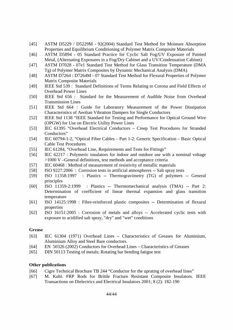
44/44
[45] ASTM D5229 / D5229M - 92(2004) Standard Test Method for Moisture Absorption Properties and Equilibrium Conditioning of Polymer Matrix Composite Materials
[46] ASTM D5894 - 05 Standard Practice for Cyclic Salt Fog/UV Exposure of Painted Metal, (Alternating Exposures in a Fog/Dry Cabinet and a UV/Condensation Cabinet)
[47] ASTM D7028 - 07e1 Standard Test Method for Glass Transition Temperature (DMA Tg) of Polymer Matrix Composites by Dynamic Mechanical Analysis (DMA)
[48] ASTM D7264 : D7264M - 07 Standard Test Method for Flexural Properties of Polymer Matrix Composite Materials
[49] IEEE Std 539 : Standard Definitions of Terms Relating to Corona and Field Effects of Overhead Power Lines
[50] IEEE Std 656 : Standard for the Measurement of Audible Noise from Overhead Transmission Lines
[51] IEEE Std 664 : Guide for Laboratory Measurement of the Power Dissipation Characteristics of Aeolian Vibration Dampers for Single Conductors
[52] IEEE Std 1138 “IEEE Standard for Testing and Performance for Optical Ground Wire (OPGW) for Use on Electric Utility Power Lines
[53] IEC 61395 “Overhead Electrical Conductors – Creep Test Procedures for Stranded Conductors”
[54] IEC 60794-1-2, “Optical Fiber Cables – Part 1-2: Generic Specification – Basic Optical Cable Test Procedures
[55] IEC 61284, “Overhead Line, Requirements and Tests for Fittings” [56] IEC 62217 : Polymeric insulators for indoor and outdoor use with a nominal voltage
>1000 V –General definitions, test methods and acceptance criteria [57] IEC 60468 : Method of measurement of resistivity of metallic materials [58] ISO 9227:2006 : Corrosion tests in artificial atmospheres -- Salt spray tests [59] ISO 11358:1997 : Plastics -- Thermogravimetry (TG) of polymers -- General
principles [60] ISO 11359-2:1999 : Plastics -- Thermomechanical analysis (TMA) -- Part 2:
Determination of coefficient of linear thermal expansion and glass transition temperature
[61] ISO 14125:1998 : Fibre-reinforced plastic composites -- Determination of flexural properties
[62] ISO 16151:2005 : Corrosion of metals and alloys -- Accelerated cyclic tests with exposure to acidified salt spray, "dry" and "wet" conditions
Grease [63] IEC 61304 (1971) Overhead Lines – Characteristics of Greases for Aluminium,
Aluminium Alloy and Steel Bare conductors. [64] EN 50326 (2002) Conductors for Overhead Lines – Characteristics of Greases [65] DIN 50113 Testing of metals; Rotating bar bending fatigue test
Other publications [66] Cigre Technical Brochure TB 244 “Conductor for the uprating of overhead lines” [67] M. Kuhl. FRP Rods for Brittle Fracture Resistant Composite Insulators. IEEE
Transactions on Dielectrics and Electrical Insulators 2001; 8 (2): 182-190