accesorios media tension elastimold
TRANSCRIPT

In this catalogue...
Power and High Voltage
Elastimold® / Fisher Pierce® Cable Accessories ......Section A
Homac® / Blackburn® Overhead Connectors ..........Section B
Homac® Underground Distribution ..........................Section C
Boreal® Flexible Braids.............................................Section D
Russellstoll® Electrical Interconnection Systems .....Section E
Alphanumerical Index ...............................................Section F

Elastimold®
Fisher Pierce® Cable Accessories
w w w . t n b . c a
Introduction . . . . . . . . . . . . . . . . . . . . . . . . . . . . . . . . . . . . . . . . . . . .A2
Ratings . . . . . . . . . . . . . . . . . . . . . . . . . . . . . . . . . . . . . . . . . . . .A3–A4
Standard Interfaces . . . . . . . . . . . . . . . . . . . . . . . . . . . . . . . . . . . . . .A5
200 A Loadbreak . . . . . . . . . . . . . . . . . . . . . . . . . . . . . . . . . . . . .A6–A9
200 A Deadbreak . . . . . . . . . . . . . . . . . . . . . . . . . . . . . . . . . . .A10–A11
600 Series Deadbreak . . . . . . . . . . . . . . . . . . . . . . . . . . . . . . .A12–A15
600 Series Deadbreak – Cam-Op™, Link-Op™ . . . . . . . . . . . . .A16–A17
600 Series Deadbreak – Stick-Op™, Window-Op™ . . . . . . . . . .A18–A19
600 Series Deadbreak – Cable Joints . . . . . . . . . . . . . . . . . . .A20–A21
Molded Multi-Point Junctions . . . . . . . . . . . . . . . . . . . . . . . . .A22–A23
PCJ™ Power Cable Joints . . . . . . . . . . . . . . . . . . . . . . . . . . . .A24–A25
Cable Terminations . . . . . . . . . . . . . . . . . . . . . . . . . . . . . . . . .A26–A29
Shield Adapters, Sealing and Grounding . . . . . . . . . . . . . . . . .A30–A31
Equipment Bushings . . . . . . . . . . . . . . . . . . . . . . . . . . . . . . . . . . . .A32
How to Specify Size-Sensitive Products . . . . . . . . . . . . . . . . . .A33–A34
AEIC and ICEA Cable Insulation Diameter . . . . . . . . . . . . . . . . .A35–A38
WX Size Tables . . . . . . . . . . . . . . . . . . . . . . . . . . . . . . . . . . . .A39–A41
Shrink-Fit Cable Joints . . . . . . . . . . . . . . . . . . . . . . . . . . . . . .A42–A43
Ranger2™ Terminations . . . . . . . . . . . . . . . . . . . . . . . . . . . . . .A44–A49
Faulted Circuit Indicators . . . . . . . . . . . . . . . . . . . . . . . . . . . . .A50–A57
Underground Distribution Switchgear . . . . . . . . . . . . . . . . . . .A58–A69
Molded Fuse Products . . . . . . . . . . . . . . . . . . . . . . . . . . . . . . .A70–A79
Surge Arresters . . . . . . . . . . . . . . . . . . . . . . . . . . . . . . . . . . . .A80–A85
Molded Vacuum Recloser . . . . . . . . . . . . . . . . . . . . . . . . . . . . .A86–A87
Table of Contents
A1

Elastimold® Cable Accessories
A2 w w w . t n b . c a
Separable Elbow Connectors and their related accessories are available in 200 A loadbreak, 200 A deadbreak and 600 A deadbreak styles. Rated for padmount,subsurface, vault, indoor, outdoor and other applications, units feature interchangeable interfaces which can be easily engaged or separated to provide a convenient method toconnect or disconnect cable and equipment in a distribution system.
Introduction
This section provides an easy-to-use, comprehensive listing of Elastimold® products for5 kV thru 35 kV underground power distribution systems. Included are separable elbowconnectors, cable joints, terminations and other cable accessory components. Thiscatalogue incorporates information relative to product application, ratings and selection.
The Thomas & Betts Elastimold® brand is recognized as the leading producer of premoldedcable accessory components worldwide. Utilizing specially formulated materials with 100%peroxide-cured insulation and shielding, Elastimold products represent the state-of-the-artin premolded process technology. Durable, quality construction and non-degrading, high-reliability, maintenance-free performance is assured when specifying Elastimold products.
Elastimold’s broad line of premolded products offers significant advantages over field-fabricated and other alternatives, including: 100% factory assurance testing prior todelivery and installation; simplified, single-piece construction with built-in insulating, shielding and sealing surfaces; ease of installation with no special skills or tools required;and compact, lightweight, durable designs for easy handling and application.
Elastimold Special Component Services Group provides custom products tailored to specific application requirements. Please contact the factory for further information regarding this service. For Surge Arresters see pages A80 to A85 and FusedElbows, see pages A70 to A79.
Cable Joints are available in permanently crimped or bolted (separable) connectorstyles. Permanently crimped units are rated the same as the cable they are connecting and are available for all applications including direct buried.
Cable Terminations are available in single-piece or modular designs. Rated for indoor,outdoor or padmount applications, units allow connection and transition from shielded underground cables to bare overhead conductors and live-front equipment.

Elastimold® Cable Accessories
A3w w w . t n b . c a
RatingsCertified Tests and PerformanceElastimold® Separable Connectors, Cable Joints, Cable Terminators and other cable accessory products have been designed and tested per applicable portions of IEEE, ANSI and other industry standards including:
• IEEE 386™ Standard For Separable Connectors
• IEEE 404™ Standard For Cable Joints and Splices
• IEEE 48™ Standard For Cable Terminations
• IEEE 592™ Standard For Exposed Semiconducting Shields
• ANSI C119.4 Standard For Copperand Aluminum Conductor Connectors
• AEIC CS8 Standards For XLPand EPR Insulated Cables
• ICEA S-94-649-2004 and S-97-682-2000 Standard for Cables Rated 5,000 – 46,000 V
Cable Joints and Terminations Ratings
Refer to the pages listed below for rating information:
• PCJ Cable Joints, page A24 • Cable Terminations, page A26 to A29
Separable Connector Ratings
Table 1 shows voltage and current ratings which apply to all Separable Connectors including 200 A Loadbreak, 200 A Deadbreak and 600 Series Deadbreak products. Table 2 shows switching and fault close ratings which only apply to 200 A Loadbreak Connectors.

Elastimold® Cable Accessories
A4 w w w . t n b . c a
Table 1 15 kV Class Ratings 25 kV Class Ratings 35 kV Class Ratings
• OPERATING VOLTAGEMaximum line-to-ground (See Application Info Note 1)
8.3 kV 15.2 kV 21.1 kV
• BIL Impulse withstand 1.2 x 50 microsecond wave 95 kV 125 kV 150 kV
• WITHSTAND VOLTAGEAC One MinuteDC Fifteen Minute
34 kV53 kV
40 kV78 kV
50 kV103 kV
• CORONA EXTINCTION LEVEL @ 3pC Sensitivity 11 kV 19 kV 26 kV
200 A ProductsContinuous Current:Symmetrical Momentary Current:
600 Series ProductsContinuous Current:Symmetrical Momentary Current:
200 A*10 kA sym, 10 cycle duration
600 and 900 A*25 kA sym, 10 cycle duration
Table 2 Loadmake/Loadbreak Switching Fault Close
15 kVClass Ratings
• 1ø and 3ø circuits 8.3 kV line to ground, 14.4 kV max. across open contacts.• 10 loadmake/break operations at 200 A max. with 70 to 80% lagging power factor.
1 fault close operation at 8.3 kV or 14.4 kV; 10,000 A, rms, sym. 10 cycles (0.17 sec.)1.3 max. asym factor applies to new or used mating parts (up to maximum designated switching operations.)
25 kVClass Ratings
• 1ø and 3ø circuits 15.2 kV line to ground, 26.3 kV max. across open contacts.• 10 loadmake/break operations at 200 A max. with 70 to 80% lagging power factor.
1 fault close operation at 15.2 kV or 26.3 kV; 10,000 A, rms, sym. 10 cycles (0.17 sec.)1.3 max. asym factor applies to new or used mating parts (up to maximum designated switching operations.)
35 kVClass Ratings
• 1ø and 3ø circuits 21.1 kV line to ground, 36.6 kV max. across open contacts.• 10 loadmake/break operations at 200 A max. with 70 to 80% lagging power factor.
1 fault close operation at 21.1 kV or 36.6 kV; 10,000 A, rms, sym. 10 cycles (0.17 sec.)1.3 max. asym factor applies to new or used mating parts (up to maximum designated switching operations.)
Application Information:
1. Loadbreak connectors are designed and rated for use on grounded WYE systems. For application on ungrounded WYE or delta systems,the next higher voltage class product is recommended. Examples: 5 kV ungrounded: use 15 kV class products; 15 kV ungrounded: use 25 kV class products; 25 kV ungrounded: use 35 kV class products.
2. Products are designed and constructed for all applications including padmount, subsurface, vault, indoor, outdoor, direct sunlight, direct buried and continuously submerged in water.
3. Products are designed and rated for ambient temperatures of -40°C to +65°C. It is recommended that loadbreak connectors be hotstick operated at -20°C to +65°C ambient temperature range and at altitudes not exceeding 6000 ft.
* Designed for 90°C maximum continuous operating temperature
RatingsCertified Tests and Performance (cont’d)

Elastimold® Cable Accessories
A5w w w . t n b . c a
Standard Interfaces
Standard Interfaces for Separable Connectors,Components and Equipment Bushings
ANSI/IEEE Standard 386 defines the specific interface dimensions that 200 A and 600 Series elbows, inserts, junctions, equipment bushingsand any mating components must conform to insure interchangeability. The table below provides information concerning the types of interfacessupplied by Elastimold for various applications and is useful to assure proper matching of components.
BushingInterface
VoltageClass
InterfaceDescription
Standard No.Figure No
200 A DEEPWELLEQUIPMENT BUSHING
15 kV, 25 kVand 35 kV
200 A BushingWell Interface
8.3 kV, 15.2 kV,21.1 kV
IEEE386-2001
Fig. 3
200 A LOADBREAK INSERT
15 kV 200 A Loadbreak
8.3 kV and8.3 kV/14.4 kV
IEEE386-2001
Fig. 5
200 A LOADBREAK INSERT
25 kV200 A Loadbreak
15.2 kV and15.2 kV/26.3 kV
IEEE386-2001
Fig. 7, Note 1
200 A LOADBREAK INSERT
35 kV
200 A LoadbreakInterface No. 2
21.1 kV and21.1 kV/36.6 kV
IEEE386-2001
Fig. 7, Note 1
200 A DEADBREAK INSERT
15 kV and 25 kV 200 A Deadbreak8.3 kV and 15.2 kV
IEEE386-2001
Fig. 4
600 SERIES EQUIPMENT BUSHING
15 kV and 25 kV600 A Deadbreak
Interface No.18.3 kV and 15.2 kV
IEEE386-2001
Fig. 11
600 SERIES EQUIPMENT BUSHING
35 kV600 A Deadbreak
Interface No.121.1 kV
IEEE386-2001
Fig. 13
1. Elastimold uses Fig. 7 interface for both 25 and 35 kV applications.
A
B
C
D
E
F
G
A
B
C
D
E
F
G

Elastimold® Cable Accessories
A6 w w w . t n b . c a
200 A Loadbreak
200 A loadbreak connectors and accessories provide a convenientmethod to connect/disconnect cable and equipment on powerdistribution systems. Loadbreak elbows include provisions forenergized operation using standard hotstick tools, allowingloadmake/break operation and a visible disconnect. Components canbe isolated with insulated caps, plugs and parking bushings.
Optional accessories allow system grounding, testing,bypass, lightning surge protection and current limiting fusing.Additional connecting points and taps can be provided by useof junctions or feed-thrus.
Ratings OverviewSee page A3–A4 for complete information including switchingand fault close ratings.
Current Ratings200 A Continuous10 kA sym., 10 Cycles
Voltage Ratings15 kV Class 8.3 kV Phase-to-Ground14.4 kV Phase-to-Phase95 kV BIL34 kV AC Withstand53 kV DC Withstand11 kV Corona Extinction25 kV Class15.2 kV Phase-to-Ground26.3 kV Phase-to-Phase125 kV BIL40 kV AC Withstand78 kV DC Withstand19 kV Corona Extinction35 kV Class21.1 kV Phase-to-Ground36.6 kV Phase-to-Phase150 kV BIL50 kV AC Withstand103 kV DC Withstand26 kV Corona Extinction
200 A LOADBREAK SEPARABLE CONNECTOR COMPONENTSCABLE TO EQUIPMENTCONNECTIONS
BUSHINGWELL
LOADBREAKBUSHING INSERT
EXTENDEDBUSHING INSERT
BUSHING WELLPLUG
LOADBREAKFEED-THRU INSERT
BOLTEDELBOWW/TAP
OPERATING ACCESSORIES
INSULATED PARKINGBUSHING
FEED THRU
PARKINGSTAND
GROUNDINGPLUG
LOADBREAK ELBOW CONNECTORWITH OR WITHOUT TEST POINT
REPLACEMENTELBOW
REPAIRELBOW
GROUNDINGELBOW
FUSED ELBOW
INSULATED CAP
INSULATED CAPWITH GROUND
ASSEMBLY TOOL
SEE PAGESA80 TO A85 FORSURGE ARRESTERAPPLICATIONS

Elastimold® Cable Accessories
A7w w w . t n b . c a
200 A Loadbreak
Illustration(not to scale) Description Voltage
ClassELASTIMOLDCat. No.
Notes
ElbowConnector
15 kV 165LR-W5XUse Tables W1 and X1 N2, 3, 4, 5
25 kV 275LR-W5XUse Tables W16 and X1 N2, 3, 4, 5
35 kV 375LR-W5XUse Tables W3 and X2 N2, 3, 5
ElbowConnector
w/ Test Point
15 kV 166LR-W5XUse Tables W1 and X1 N2, 3, 4, 5, 24
25 kV 276LR-W5XUse Tables W16 and X1 N2, 3, 4, 5, 24
35 kV 376LR-W5XUse Tables W3 and X2 N2, 3, 5, 24
Jacket SealElbow
Connector
15 kV 165LRJS-W5XUse Tables W1 and X1 N2, 19
25 kV 275LRJS-W5XUse Tables W16 and X1 N2, 19
Jacket SealElbow
Connectorw/ Test Point
15 kV 166LRJS-W5XUse Tables W1 and X1 N2, 19, 24
25 kV 276LRJS-W5XUse Tables W16 and X1 N2, 19, 24
Repair ElbowConnector
15 kV 167ELR-W5XUse Tables W5 and X1 N5, 10, 18
25 kV 273ELR-W5XUse Tables W5 and X1 N5, 10, 18
Repair ElbowConnector
w/ Test Point
15 kV 168ELR-W5XUse Tables W5 and X1 N5, 10, 18, 24
25 kV 274ELR-W5XUse Tables W5 and X1 N5, 10, 18, 24
ReplacementElbow
15 kV 167RLR-W5XUse Tables W4 and X1 N5, 11, 13
25 kV 273RLR-W5XUse Tables W2 and X1 N5, 11, 13
ReplacementElbow
w/ Test Point
15 kV 168RLR-W5XUse Tables W4 and X1 N5, 11, 13, 24
25 kV 274RLR-W5XUse Tables W2 and X1 N5, 11, 13, 24
Direct TestElbow
Connector
15 kV 167DLR-W5XUse Tables W4 and X1 N2, 5, 22
25 kV 273DLR-W5XUse Tables W2 and X1 N2, 5, 22
Direct TestRepair Elbow
Connector
15 kV 167DELR-W5XUse Tables W5 and X1 N5, 10, 18, 22
25 kV 273DELR-W5XUse Tables W5 and X1 N5, 10, 18, 22
Direct TestRepair Elbow
Connectorw/ Test Point
15 kV 168DELR-W5XUse Tables W5 and X1 N5, 10, 18, 22, 24
25 kV 274DELR-W5XUse Tables W5 and X1 N5, 10, 18, 22, 24
Fused Elbow(Full Range
Current Limiting)
15 kV25 kV
168FLR H-W0X274FLR H-W0XSee Product GuidePG-PC-H
Bolted Elboww/ Tap 15 kV 167LRT-W5X
Use Tables W4 and X1 N17
Bushing Insert
15 kV25 kV35 kV35 kV
1601A42701A43701A43701A3
N4, 8, 20N4, 8, 20N6, 21N8, 21
ExtendedBushing Insert
15 kV25 kV
1601EA42701EA4
N8, 20N8, 20
Feed-ThruInsert
15 kV25 kV35 kV
1602A3R2702A13702A1
N16N16N6, 16
Insulated Cap 15 kV 160DR N9
Insulated Capw/ Ground
15 kV15 kV25 kV35 kV
160DRG167DRG273DRG375DRG
N9N7, 9N7, 9N7, 9
N1. Copper lug for use on COPPER CONDUCTOR ONLY.N2. W5X indicates that the Cat. No. includes 02500X long
bi-metal compression lug as standard. For an all-copper lug, replace W5X with W2X in Table X1 to specify the all-copper 02702X lug.
N3. Also available as housing only. Specify: 165BLR-W; 275BLR-W; 375BLR-W; 166BLR-W; 276BLR-W; 376BLR-W.
N4. Also available as elbow/insert combination. Specify: 165A4-WX; 275A4-WX; 166A4-WX; 276A4-WX.
N5. Also available with 200ECS jacket seal included.Add - “S” suffix to Cat. No.
N6. Rated for single-phase applications only.N7. Equipped with insulated cuff.N8. Includes internal torquing feature using 200AT
Assembly Tool.N9. Also available without probe. Specify “A” suffix -
Example: 273DRGA.N10.Repair elbow has extended length contact and elbow
housing resulting in a net gain of 3-1/4 in. length.N11.Replacement elbow has extended length contact and
elbow housing resulting in a net gain of 8-7/8 in. length.
N12.Rated for 25 kV thru 35 kV applications.N13.Includes long bi-metal contact 00400X.N14.160CA Cable Size Adapter can only be used with
elbow Cat. No. 165LR/166LR C size only.N16.Fully rotatable for 360° positioning. Includes bail
assembly to secure feed-thru insert to bushing well.N17.Includes 02800X bi-metal contact.N18.Includes 02509X long bi-metal contact.N19.Includes built-in jacket seal. Also available as
housing only — specify: 165BLRJS-W, 166BLRJS-W,275BLRJS-W or 276LRJS-W. Also available as elbow/insert combination — specify: 165JSA4-W5X, 166JSA4-W5X, 275JSA4-W5X or 276JSA4-W5X.
N20. Includes a yellow seating indicator and vent ring.N21. Includes a black vent ring.N22. Direct Test Connectors, along with a 200TC-X series
meter adapter, a properly rated voltage meter and Hot-line Stick provides a means for direct conductor voltage testing.
N23. With stainless steel bracket.N24.Test Point Cap Cat# 156-7
Refer to the W and X tables on pages A39 to A41 for sizing to cable insulation diameter and conductor size.For cable shield adapters and jacket seals, see page A30.
Illustration(not to scale)
DescriptionVoltageClass
ELASTIMOLDCat. No. Notes
Insulated Capw/ Ground and
Test Point
15 kV 168DRG N725 kV 274DRG N735 kV 376DRG N7
Grounding Plug (1/0 AWG x 6’ Ground Lead)
15 kV 161GP25 kV 272GP
Grounding Elbow(1/0 AWG x 6’ Ground Lead)
15 kV 160GLR
25/35 kV 370GLR N12
Feed-Thru
15 kV 164FT25 kV 274FT35 kV 371FT N1635 kV 373FT
Feed-ThruVertical
15 kV 164FTV25 kV 274FTV35 kV 373FTV
Adjustable Bracket2-point Feed-Thru
15 kV 164FT2-AB N2325 kV 274FT2-AB N2335 kV 373FT2-AB N23
Adjustable Bracket3-point Feed-Thru
15 kV 164FT3-AB N2325 kV 274FT3-AB N2335 kV 373FT3-AB N23
Adjustable Bracket4-point Feed-Thru
15 kV 164FT4-AB N2325 kV 274FT4-AB N2335 kV 373FT4-AB N23
Feed-Thru Well 15/25 kV K1601WFT
Feed-Thru Well Vertical 15/25 kV K1601WFTV
Insulated Parking Bushing
15 kV 161SOP N2025 kV 272SOP N2035 kV 372SOP N2115 kV 164SOP N20, 2325 kV 274SOP N20, 23
Test Rod ALL 370TR
Bushing Well Plug15/25 kV 276BWP
35 kV M276BWPAssembly Tool ALL 200AT N8
CONTACTS, PROBES, PLUGS, CABLEADAPTERS AND JUNCTIONS CONTINUED ON PAGE A9.

Elastimold® Cable Accessories
A8 w w w . t n b . c a
200 A Loadbreak
See page A3–A4 for complete informationincluding switching and fault close ratings.
Current Ratings200 A Continuous10 kA sym., 10 Cycles
Voltage Ratings15 kV Class8.3 kV Phase-to-Ground14.4 kV Phase-to-Phase95 kV BIL34 kV AC Withstand53 kV DC Withstand11 kV Corona Extinction
25 kV Class15.2 kV Phase-to-Ground26.3 kV Phase-to-Phase125 kV BIL40 kV AC Withstand78 kV DC Withstand19 kV Corona Extinction35 kV Class21.1 kV Phase-to-Ground36.6 kV Phase-to-Phase150 kV BIL50 kV AC Withstand103 kV DC Withstand26 kV Corona Extinction
Ratings Overview
200 A LOADBREAK SEPARABLE CONNECTOR COMPONENTS
SEE PAGESA70 TO A 79 FOR
FUSEDELBOW SELECTION
SEE PAGESA80 TO A 85 FORSURGE ARRESTERAPPLICATIONS
CABLE TO CABLECONNECTIONS 4-POINT
JUNCTION3-POINTJUNCTION
2-POINTJUNCTION
LOADBREAKBUSHING INSERT
LOADBREAKBUSHING INSERT
LOADBREAKBUSHING INSERT
2 POINT WELLJUNCTION
3 POINT WELLJUNCTION
4 POINT WELLJUNCTION

Elastimold® Cable Accessories
A9w w w . t n b . c a
200 A Loadbreak
N1. Repair elbow has extended length contact and elbow housing resulting in a net gain of 3-1/4 in. length. N2. Copper lug for use on COPPER CONDUCTOR ONLY.N3. Replacement elbow has extended length contact and elbow housing resulting in a net gain of 8-7/8 in.length.N4. 160CA Cable Size Adapter can only be used with elbow part numbers 165LR/166LR C size only.N5. Also available as rubber only, without straps. Specify suffix “-4” in place of “-5” in the Cat. No.N6. Supplied with replaceable stud. Replacement stud available separately. Specify 1000-150.N7. Hardware packages, consisting of brackets and straps only, may be ordered separately by specifying “-6” in the
Cat. No. Example 164J4-6N8. Hardware package, consists of “U”-straps and back plate only, may be ordered separately by specifying
1601US-J2.N9. Hardware package, consists of “U”-straps and back plate only, may be ordered separately by specifying
1601US-J3.N10.Hardware package, consists of “U”-straps and back plate only, may be ordered separately by specifying
1601US-J4.N11.Hardware package, consists of “U”-straps and back plate only, may be ordered separately by specifying 271-68.N12.Hardware package, consists of “U”-straps and back plate only, may be ordered separately by specifying 271-61.N13.Hardware package, consists of “U”-straps and back plate only, may be ordered separately by specifying 271-70.N14.For use with Direct Test Connectors.
Illustration(not to scale) Description Voltage
ClassELASTIMOLDCat. No.
Notes
Contacts:Long Bi-MetalELR Bi-Metal
CopperLRT ContactRLR Contact
ALL15/25 kV02702X02800X15/25 kV
Use Table X102500X02509X02702X02800X00400X
N1N2
N3
Elbow Probe15 kV25 kV35 kV
166LRF274LRF375LRF
ElbowCable EntranceInsulating Plug
ALL 10EPWUse Table W6
Cable SizeAdapter 15 kV
160CA-WUse Table W6EB-FA Only
N4
Direct Voltage TestMeter Adapter for:HD Electric Meters
ALL
200TC-1 N14
Ross Meters 200TC-2 N14
Chance Meters 200TC-4 N14
2-Way WellJunction w/s.s. Bracket
15/25 kV K1601WJ2 N6
2-Way WellJunction w/“U” Straps
15/25 kV K1601WJ2-5 N5, 6, 11
3-Way WellJunction w/s.s. Bracket
15/25 kV K1601WJ3 N6
3-Way WellJunction w/“U” Straps
15/25 kV K1601WJ3-5 N5, 6, 12
4-Way WellJunction w/s.s. Bracket
15/25 kV K1601WJ4 N6
4-Way WellJunction w/“U” Straps
15/25 kV K1601WJ4-5 N5, 6, 13
Illustration(not to scale) Description Voltage
ClassELASTIMOLDCat. No.
Notes
2-Point Junctionwith/StainlessSteel bracket
15 kV25 kV35 kV
164J2274J2373J2
N7N7N7
2-Point Junctionw/“U”-straps
15 kV25 kV35 kV
164J2-5274J2-5373J2-5
N5, 8N5, 11N5, 11
3-Point Junctionwith/StainlessSteel bracket
15 kV25 kV35 kV
164J3274J3373J3
N7N7N7
3-Point Junctionw/“U”-straps
15 kV25 kV35 kV
164J3-5274J3-5373J3-5
N5, 9N5, 12N5, 12
4-Point Junctionwith/StainlessSteel bracket
15 kV25 kV35 kV
164J4274J4373J4
N7N7N7
4-Point Junctionw/“U”-straps
15 kV25 kV35 kV
164J4-5274J4-5373J4-5
N5, 10N5, 13N5, 13

Elastimold® Cable Accessories
A10 w w w . t n b . c a
200 A Deadbreak
200 A deadbreak connectors and accessories provide a quickdisconnect feature for cable and equipment connections on powerdistribution systems.
All deadbreak connectors must be DE-ENERGIZED before operatingand must be mechanically secured with bails when connected.Components can be isolated with insulated caps, plugs andparking bushings.
All deadbreak elbows are equipped with test points as standard.Optional accessories allow system grounding, bypass and lightningsurge protection. Additional connecting points and taps can beprovided by use of junctions or feed-thrus.
See page A3–A4 for complete information including switchingand fault close ratings.
Current Ratings200 A Continuous10 kA sym., 10 Cycles
Voltage Ratings15 kV Class 8.3 kV Phase-to-Ground14.4 kV Phase-to-Phase95 kV BIL34 kV AC Withstand53 kV DC Withstand11 kV Corona Extinction25 kV Class15.2 kV Phase-to-Ground26.3 kV Phase-to-Phase125 kV BIL40 kV AC Withstand78 kV DC Withstand19 kV Corona Extinction
Ratings Overview200 A DEADBREAK SEPARABLE CONNECTOR COMPONENTS
OPERATINGACCESSORIES
BUSHING PLUG WELL
CABLE TO EQUIPMENT
INSULATED CAP
EXCEPT FOR LOCKINGSPLICES ALL 200 DEADBREAK
PRODUCTS MUST BEMECHANICALLY SECURED
WITH A BAIL WHEN CONNECTED
CABLE TO CABLECONNECTIONS
STRAIGHT RECEPTACLE
BELOWCONNECTOR
BUSHINGINSERT
DEADBREAKFEED-THRU INSERT
INTEGRAL BUSHING
PARKINGSTAND
FEED THRU
TEE SPLICE
IN-LINE JUNCTION
STRAIGHT PLUG
INSULATED PLUG
GROUNDING PLUG
STAND-OFF PLUG
4-POINTJUNCTION
3-POINTJUNCTION
2-POINTJUNCTION
LOCKING“Y” SPLICE
LOCKING ANDREPAIR SPLICE
BUSHINGWELL
SEE PAGESA80 TO A 85 FORSURGE ARRESTERAPPLICATIONS

Elastimold® Cable Accessories
A11w w w . t n b . c a
Illustration(not to scale) Description Voltage
ClassELASTIMOLDCat. No.
Notes
Elbow Connectorw/ Test Point 15/25 kV 156LR-W5X
Use Tables W4 and X1 N1, 2
Direct TestElbow Connector 15/25 kV 156DLR-W5X
Use Tables W4 and X1 N1, 2, 22
Bail Assemblyfor 156LR Elbow 15/25 kV 150BA
Bushing Insert 15/25 kV BK1501A1 N3
Feed-thru Insert 15/25 kV K1502A1 N3, 4
Insulated Plug 15/25 kV K150DP N3
Insulated Cap 15/25 kV K150DR N3
Insulated ParkingBushing 15/25 kV K151SOP N3
Grounding Plug 15/25 kV 151GP N3
Feed-Thru 15/25 kV K1501FT N3, 6
2-Point Junction 15/25 kV K1501J2-U N3, 6
3-Point Junction 15/25 kV K1501J3-U N3, 6
4-Point Junction 15/25 kV K1501J4-U N3, 6
Elbow Probe 15/25 kV 156LRF
StraightReceptacle 15/25 kV K151SR-W0X
Use Tables W1 and X1 N3, 12, 13, 17, 18
Straight Plug 15/25 kV K151SP-W0XUse Tables W1 and X1 N3, 12, 13, 19
Tee Splice 15/25 kV K150T N3
In-Line Junction 15/25 kV K150S N3
Locking Splice/Repair Splice 15/25 kV K151LS-W0X
Use Tables W1A and X1N8, 9, 13, 15, 16,17, 20, 23
Locking “Y”Splice 15/25 kV K151LY-W0X
Use Tables W1A and X1 N8, 9, 13, 15, 17, 21
BAIL 15/25 kV 150TB1 N5
BAIL 15/25 kV 150TB2 N5
BAIL 15/25 kV 150TB3 N5
N1. Includes bail assembly.N2. W5X indicates that the Cat. No. includes a 02500X bi-metal compression lug, which is rated for either aluminum
or copper conductor, as standard. For an all-copper lug, replace W5X with W2X in Table X1 to specify the all-copper 02702X lug.
N3. Bails are required but not included. Order separately. Consult factory for bails not listed for a specific application.N4. Fully rotatable for 360º positioning. Includes bail assembly to secure feed-thru insert to bushing well. Elbows
bail assemblies are required but not included with the feed-thru insert.N5. Refer to factory for application details.N6. Center-to-center spacing equals 4 in.N7. Copper lug for copper cable only.N8. To order cable legs for different cable sizes, list each leg size “W” and “X”.
Example: K151LY-A1240-A1240-B1220. See Tables W1 and X1 for sizes.N9. To order locking contacts for K151LS and K151LY, order 01401X (Al) or 01402X (Cu) for plug contact.
Order 01301X (Al) or 01302X (Cu) for receptacle. See Table X1 for sizes.N10.For use with 156LR elbows.N11.For use with K151SR, K151SP, K151LS, K151LY receptacles, plugs and splices.N12.Also available as housing only. Specify K151BSP-W or K151BSR-W.N13.Also available in EB-FA sizes per table W6 by using 160CA cable adapter with C size plugs and receptacles.N14.160CA cable adapter can only be used with C size plugs and receptacles.N15.Bails are not required for locking splices.N16.When used as a repair splice, the assembled length allows 4 in. for cable replacement/repair.N17.Straight receptacles are also available with test point. Specify K152SR-W0X Cat. No.N18.W0X indicates that the Cat. No. includes a 01500X universal aluminum compression lug, which is rated for
either aluminum or copper, as standard. For an all-copper lug, replace W0X with W2X in Table X1 to specify the all-copper 01502X lug.
N19.W0X indicates that the Cat. No. includes a 01600X universal aluminum compression lug, which is rated for either aluminum or copper, as standard. For an all-copper lug, replace W0X with W2X in Table X1 to specify the all-copper 01602X lug.
N20.W0X indicates that the Cat. No. includes a 01400X universal aluminum compression lug, which is rated for either aluminum or copper, as standard. For an all-copper lug, replace W0X with W2X in Table X1 to specify the all-copper 01402X lug.
N21.W0X indicates that the Cat. No. includes a 01300X universal aluminum compression lug, which is rated for either aluminum or copper, as standard. For an all-copper lug, replace W0X with W2X in Table X1 to specify the all-copper 01302X lug.
N22.Direct Test Connectors, along with a 200TC-X series meter adapter, a properly rated voltage meter and Hot-line Stick provides a means for direct conductor voltage testing. See page A13 for meter adapters.
N23.Gains approximately 4 in. of repair length.
Refer to the W and X tables on pages A39 to A41 for sizing to cable insulation diameter and conductor size.For cable shield adapters and jacket seals, see page A30.
200 A Deadbreak
Illustration(not to scale) Description Voltage
ClassELASTIMOLDCat. No.
Notes
BAIL 15/25 kV 150TB4 N5
BAIL 15/25 kV 150TB5 N5
Contacts:Long Bi-Metal
Copper
15/25 kV15/25 kV
02500X02702X N7
ElbowCable EntranceInsulating Plug
15/25 kV 10EP-WUse Table W6
N10
Cable EntranceInsulating Plug 15/25 kV 152EA-W
Use Table W6N11
Cable SizeAdapter 15/25 KV
160CA-WUse Table W6EB-FA Only
N14

Elastimold® Cable Accessories
A12 w w w . t n b . c a
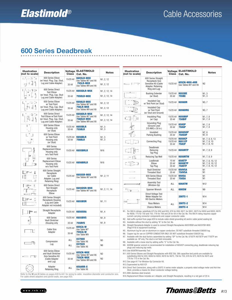
600 Series Deadbreak
600 Series deadbreak elbows, straight receptacles, junctions, vaultstretchers and accessories are used to connect equipment and cableon primary feeder and network circuits. Designs accommodate largeconductors and feature bolted connections and deadfront modularconstruction for maximum reliability, performance and versatility.
DE-ENERGIZED connectors can be quickly and easily connected anddisconnected using standard hand tools and equipment in accordancewith accepted operating practices. Optional accessories allow visibleexternal separation, by-pass, isolation, dead-ending, grounding, andtesting as well as adding taps, surge arresters and circuit protection.
Hotstick operable and separable joint systems are shownon pages A16 thru A21.
See page A3–A4 for complete information.
Current Ratings(Prefixes: 650, K650, K655, K656,750, 755, 756 and 03700)600 A Continuous25 kA sym., 10 cycles(Prefixes 675, K675, K676,775, 776 and 03702)900 A Continuous25 kA sym., 10 cycles
Note: 900 A ratings require copper cable and coppercurrent-carrying components.
VOLTAGE RATINGS15/25 kV Class (5 kV thru 28 kV)16.2 kV Phase-to-Ground28 kV Phase-to Phase140 kV BIL45 kV AC Withstand84 kV DC Withstand21.5 kV Corona Extinction35 kV Class21.1 kV Phase-to-Ground36.6 kV Phase-to-Phase150 kV BIL50 kV AC Withstand103 kV DC Withstand26 kV Corona Extinction
Note: Elastimold has increased the IEEE StandardProd uction and Design Test levels for 25 kV Classproducts to include 27 kV and 28 kV systems.
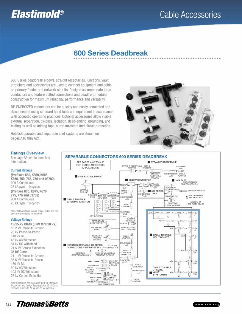
Ratings OverviewSEPARABLE CONNECTORS 600 SERIES DEADBREAK
CABLE TO CABLEUTILIZING-KITS
STRAIGHT RECEPTACLESEE PAGES A80 TO A 85FOR SURGE ARRESTERS
APPLICATIONS
ELBOW CONNECTOR
600 SERIESTAPS
CABLE TO EQUIPMENT
CABLE TO CABLE(UTILIZING JUNCTION)SEE PAGES A22 AND A23FOR ADDITIONALJUNCTIONS
INTEGRALBUSHING
THREADEDSTUD
BUSHINGEXTENDER
CONNECTINGPLUG
4 PT JUNCTION
3 PT JUNCTION
2 PT JUNCTION
OPERATINGACCESSORIES
GROUNDINGPLUG
INSULATEDPARKINGBUSHING
HOTSTICK OPERABLE 600 SERIESCONNECTORS – SEE PAGES A16-A19
STICK-OPSEE PAGES.A18 & A19
THREADEDCOMPRESSION LUG
STICK-OP LOADBREAKREDUCING TAP PLUG
LINK-OPSEE PAGESA16 & A17
LINK CONNECTORLINK-OP
CAM-OPLINK CONNECTOR
CAM-OPRETAINER SLEEVES
CAM-OPSEE PAGES A16 & A17
LINK-OPRETAINERSLEEVES
STRAIGHT RECEPTACLEADAPTER
BOLT &WASHERS
STRAIGHTRECEPTACLEHOUSING
RETAININGRING
CABLEADAPTER
200A TAPS200A DEADBREAK
SEE PAGES A10 & A11
DEADBREAKREDUCINGTAP PLUG
LOADBREAKELBOW TAP PLUG
REDUCING TAPWELL
SPANNER WRENCH
200 A DEADBREAKSEE PAGES A6 & A7
WINDOW-OPSEE PAGES A18 & A19
CABLE TO CABLEUTILIZINGVAULT STRETCHERS
L-4
L-3
L-2
L-1
VS2
VS3
VS4
COMPRESSIONLUG
CABLEADAPTER
COMPRESSIONLUG
VAULTSTRETCHERTHREADED
STUD
VAULTSTRETCHERCONNECTOR
COMPRESSIONLUG
CABLEADAPTER
INSULATED CAPWITH TEST POINT
BUSHINGEXTENDER
THREADEDSTUD
CABLEADAPTER
COMPRESSIONLUG
600SERIESELBOW
THREADEDSTUD
CONNECTINGPLUG
VOLTAGEDETECTION
CAPINSULATING
PLUG
SEE PAGE A14 & A15
SEE PAGE A14 & A15
Elastimold® Cable Accessories
A13w w w . t n b . c a
Illustration(not to scale) Description Voltage
ClassELASTIMOLDCat. No.
Notes
600 Series Elbow(w/ Insul. Plug, Cap, Stud,Lug and Cable Adapter)
15/25 kV
35 kV
K655LR-W0XUse Tables W7 and X6755LR-W0X
Use Tables W9 and X6
N1, 2, 12
N1, 2, 12
600 Series DirectTest Elbow
(w/ Insul. Plug, Cap, StudLug and Cable Adapter)
15/25 kV
35 kV
K655DLR-W0X
755DLR-W0X
N1, 2, 12, 14
N1, 2, 12, 14
600 Series Elboww/ Test Point
(w/ Insul. Plug, Cap, StudLug and Cable Adapter)
15/25 kV
35 kV
K656LR-W0XUse Tables W7 and X6756LR-W0XUse Tables W9 and X6
N1, 2, 12
N1, 2, 12
600 Series DirectTest Elbow w/Test Point
(w/ Insul. Plug, Cap, Stud,Lug and Cable Adapter)
15/25 kV
35 kV
K656DLR-W0XUse Tables W7 and X6756DLR-W0XUse Tables W9 and X6
N1, 2, 12, 14
N1, 2, 12, 14
600 Series ElbowHousing only
(w/ Stud)
15/25 kV35 kV
K655BLR755BLR
N1, 3N1, 3
600 Series Elboww/ Test PointHousing only
(w/ Stud)
15/25 kV35 kV
K656BLR756BLR
N1, 3N1, 3
600 SeriesReplacement Elbow
Housing only w/o Test Point
15/25 kV K655BRLR N16
600 SeriesReplacement Elbow
Housing only w/o Test Point
15/25 kV K656BRLR N16
600 Series StraightReceptacle(w/ Cable
Adapter, Lug andRetaining Ring)
15/25 kV K655SR-W0XUse Tables W7 and X6 N1 ,2, 11
600 Series DirectTest StraightReceptacle
Elbow
15/25 kV K655DSR-W0XUse Tables W7 and X6 N1, 2, 11, 14
600 Series StraightReceptacle Housing
(Lug and CableAdapter not included)
15/25 kV K655BSR N1, 11
Straight ReceptacleAdapter 15/25 kV K650SRA N1, 4
600 SeriesVault Stretcher(Housing only
15/25 kV
35 kV
K655BVS
755BVS
N1, 9
N1, 9
Cable SizeAdapter
15/25 kV
35 kV
655CA-WUse Table W7755CA-WUse Table W9
CompressionLug
ALL
ALL
03700XUse Table X603702XUse Table X6
N5
N6
600 Series Elbowand Vault StretcherSize Sensitive Kit(Cable Adapter
and Lug)
15/25 kV
35 kV
655CK-W0XUse Tables W7 and X6755CK-W0XUse Tables W9 and X6
N2
N2
AdapterRetaining Ring ALL 650ARR-X
Use Table X6
600 Series Deadbreak
Illustration(not to scale) Description Voltage
ClassELASTIMOLDCat. No.
Notes
600 Series StraightReceptacle Size
Sensitive Kit (CableAdapter, Retaining
Ring and Lug)
15/25 kV 655CK-W0X-ARRUse Tables W7 and X6 N2
Bushing Extender(w/ Stud)
15/25 kV35 kV
K655BE755BE
N1, 3N1, 3
Insulated Cap w/ Test Point (w/ Stud) 15/25 kV K656DR N3, 7
Insulated Capw/ Test Point
(w/ Stud and Ground)15/25 kV K656DRG N3, 7
Insulating Plug(w/ Cap)
15/25 kV35 kV
K650BIP750BIP
N1, 7, 8N1, 7, 8
Grounding Plug(Ground Lead
2/0 AWG x 30 in.)
15/25 kV35 kV
650GP750GP
N1, 7, 8N1, 7, 8
InsulatedParking Bushing
15/25 kV35 kV
K650SOP750SOP
N7, 8N7, 8
Connecting Plug15/25 kV15/25 kV
35 kV
K650CPK651CP750CP
N1, 7, 8, 9, 13N1, 7, 8, 10N1, 7, 8, 10
DeadbreakReducingTap Plug
15/25 kV K650RTP N1, 7, 8, 9
Reducing Tap Well 15/25 kV K650RTW N1, 7, 8, 9
LoadbreakElbow
Tap Plug
15 kV25 kV35 kV
650ETPK650ETP750ETP
N1, 7, 8, 10, 12N1, 7, 8, 10, 12N1, 7, 8, 10, 12
Vault StretcherThreaded Stud
15/25 kV35 kV
650VSA750VSA
N1N1
600 Series ElbowThreaded Stud
15/25 kV35 kV
650SA750SA
N1N1
Assembly Tool(Window-Op) ALL 600ATM N12
Spanner Wrench ALL 600SW N9
Direct Voltage TestMeter Adapter for:HD Electric Meters
ALL
200TC-1 N14
Ross Meters 200TC-2 N14
Chance Meters 200TC-4 N14
N1. For 900 A ratings, substitute 675 for 650 and 655; 676 for 656; K671 for K651; K675 for K650 and K655; K676 for K656; 775 for 750 and 755; 776 for 756 and 2X for 0X in the Cat. No. The 900 A rating requires copper current-carrying connector components and copper conductor cable.
N2. Add suffix symbol from page A29 to include cable shield grounding kit and/or cable jacket sealing kit.N3. Available without the stud by adding “N” to the Cat. No.N4. Straight Receptacle Adapter is used to connect Straight Receptacles K655YBSR and K655YSR-W0X
(Page A19) to equipment bushings.N5. Aluminum lug for use on aluminum or copper conductors. DO NOT substitute threaded 03600X lug.N6. Copper lug for use on COPPER CONDUCTOR ONLY. DO NOT substitute threaded 03602X lug.N7. Available with the stud factory-assembled by adding “SP” to the Cat. No. 675ETP, K675ETP and 775ETP are
available as -SP only. The stud is not field removable.N8. Available with a loose stud by adding suffix “S” to the Cat. No.N9. 600SW spanner wrench is recommended for installation of K650CP connecting plug, deadbreak reducing tap
plugs and reducing tap wells.N10.Use 600ATM Assembly Tool.N11.600 Series Elbows and Straight Receptacles with IEEE Std. 386 capacitive test points are available by
substituting 656 for 655; K656 for K655; K676 for K675; 756 for 755; 676 for 675; K676 for K675 and 776 for 775 in the Cat. No.
N12.See page A17 for Window-Op Connector Kit.N13.Superseded by K651CP.N14.Direct Test Connectors, along with a 200TC-X series meter adapter, a properly rated voltage meter and Hot-line
Stick; provides a means for direct conductor voltage testing.N15.With stainless steel bracket.N16.Replacement Elbow includes an I-Adapter, and Straight Receptacle, resulting in a net gain of 20 in.
Refer to the W and X tables on pages A39 to A41 for sizing to cable insulation diameter and conductor size.For cable shield adapters and jacket seals, see page A30.
Elastimold® Cable Accessories
A14 w w w . t n b . c a
600 Series Deadbreak
600 Series deadbreak elbows, straight receptacles, junctions, vaultstretchers and accessories are used to connect equipment and cableon primary feeder and network circuits. Designs accommodate largeconductors and feature bolted connections and deadfront modularconstruction for maximum reliability, performance and versatility.
DE-ENERGIZED connectors can be quickly and easily connected anddisconnected using standard hand tools and equipment in accordancewith accepted operating practices. Optional accessories allow visibleexternal separation, by-pass, isolation, dead-ending, grounding, andtesting as well as adding taps, surge arresters and circuit protection.
Hotstick operable and separable joint systems are shown on pages A16 thru A21.
See page A3–A4 for complete information.
Current Ratings(Prefixes: 650, K650, K655,K656, 750, 755, 756 and 03700)600 A Continuous25 kA sym., 10 cycles(Prefixes 675, K675, K676,775, 776 and 03702)900 A Continuous25 kA sym., 10 cycles
NOTE: 900 A ratings require copper cable and cop-per current-carrying components.
Voltage Ratings15/25 kV Class (5 kV thru 28 kV)16.2 kV Phase-to-Ground28 kV Phase-to-Phase140 kV BIL45 kV AC Withstand84 kV DC Withstand21.5 kV Corona Extinction35 kV Class21.1 kV Phase-to-Ground36.6 kV Phase-to-Phase150 kV BIL50 kV AC Withstand103 kV DC Withstand26 kV Corona Extinction
Note: Elastimold has increased the IEEE StandardProd uction and Design Test levels for 25 kV Classproducts to include 27 kV and 28 kV systems.
Ratings OverviewSEPARABLE CONNECTORS 600 SERIES DEADBREAK
CABLE TO CABLEUTILIZING-KITS
STRAIGHT RECEPTACLESEE PAGES A 80 TO A 85FOR SURGE ARRESTERS
APPLICATIONS
ELBOW CONNECTOR
600 SERIESTAPS
CABLE TO EQUIPMENT
CABLE TO CABLE(UTILIZING JUNCTION)
INTEGRALBUSHING
THREADEDSTUD
BUSHINGEXTENDER
CONNECTINGPLUG
4 PT JUNCTION
3 PT JUNCTION
2 PT JUNCTION
OPERATINGACCESSORIES
GROUNDINGPLUG
INSULATEDPARKINGBUSHING
HOTSTICK OPERABLE 600 SERIESCONNECTORS – SEE PAGES 14 - 17
STICK-OPSEE PAGES 16 & 17
THREADEDCOMPRESSION LUG
STICK-OP LOADBREAKREDUCING TAP PLUG
LINK-OPSEE PAGES14 & 15
LINK CONNECTORLINK-OP
CAM-OPLINK CONNECTOR
CAM-OPRETAINER SLEEVES
CAM-OPSEE PAGES 14 & 15
LINK-OPRETAINERSLEEVES
STRAIGHT RECEPTACLEADAPTER
BOLT &WASHERS
STRAIGHTRECEPTACLEHOUSING
RETAININGRING
CABLEADAPTER
200A TAPS200A DEADBREAKSEE PAGES 8 & 9
DEADBREAKREDUCING TAP
PLUG
LOADBREAKELBOW TAP PLUG
REDUCING TAPWELL
SPANNER WRENCH
200A DEADBREAKSEE PAGES 4 & 5
WINDOW-OPSEE PAGES 16 & 17
CABLE TO CABLEUTILIZINGVAULT STRETCHERS
L-4
L-3
L-2
L-1
VS2
VS3
VS4
COMPRESSIONLUG
CABLEADAPTER
COMPRESSIONLUG
VAULTSTRETCHER
THREADEDSTUD
VAULTSTRETCHERCONNECTOR
COMPRESSIONLUG
CABLEADAPTER
INSULATED CAPWITH TEST POINT
BUSHINGEXTENDER
THREADEDSTUD
CABLEADAPTER
COMPRESSIONLUG
600SERIESELBOW
THREADEDSTUD
CONNECTINGPLUG
VOLTAGEDETECTION
CAPINSULATING
PLUG

Elastimold® Cable Accessories
A15w w w . t n b . c a
Illustration(not to scale) Description Voltage
ClassELASTIMOLDCat. No.
Notes
2-Point Junction 15/25 kV35 kV
K650J2750J2
N1, 9, 10N1, 9, 10
3-Point Junction 15/25 kV35 kV
K650J3750J3
N1, 9, 10N1, 9, 10
4-Point Junction 15/25 kV35 kV
K650J4750J4
N1, 9, 10N1, 9, 10
1-wayL-Kit
15/25 kV35 kV
K655L1755L1
N1, 2, 3, 4N1, 2, 3, 4
2-wayL-Kit
15/25 kV35 kV
K655L2755L2
N1, 2, 3, 4, 5, 6, 7N1, 2, 3, 4, 5, 6, 7
2-wayVS-Kit
15/25 kV
35 kV
K655VSL2
755VSL2
N1, 2, 3
N1, 2, 3
3-wayL-Kit
15/25 kV
35 kV
K655L3
755L3
N1, 2, 3, 4, 5
N1, 2, 3, 4, 5
3-WayVS Kit
15/25 kV
35 kV
K655VSL3
755VSL3
N1, 2, 3, 5, 6, 7
N1, 2, 3, 5, 6, 7
4-WayL-Kit
15/25 kV35 kV
K655L4755L4
N1, 2, 3, 4, 5N1, 2, 3, 4, 5
4-WayVS-Kit
15/25 kV
35 kV
K655VSL4
755VSL4
N1, 2, 3, 5
N1, 2, 3, 5
Assembly Tool(Window-Op) ALL 600ATM N8
Spanner Wrench ALL 600SW N2
600 Series Deadbreak
N1. For 900 A ratings, substitute 675 for 650 and 655; 676 for 656; K675 for K650 and K655; K676 for K656; 775 for 750 and 755; 776 for 756 and 2X for 0X in the Cat. No. The 900 A rating requires copper current-carrying connector components and copper conductor cable.
N2. 600SW spanner wrench is recommended for installation of K650CP connecting plug, deadbreak reducing tap plugs and reducing tap wells.
N3. L-Kits and VS-Kits do not include cable adapters or compression lugs. These items must be ordered separately.N4. 600 Series Elbows and Straight Receptacles with IEEE Std. 386 capacitive test points are available by
substituting 656 for 655; K656 for K655; K676 for K675; 756 for 755; 676 for 675; K676 for K675 and 776 for 775 in the Cat. No.
N5. 600ATM is recommended for installing K651CP and 750CP.N6. Can be used as a repair joint. (Gains 3-1/2 in. of repair length)N7. Can be used as a reducing joint for different size cables.N8. See page A17 for Window-Op Connector Kit.N9. Rubber junction with stainless steel mounting plate and back plate.
Add “-U” for rubber junction with stainless steel mounting plate, back plate and adjustable mounting bracket.Add “-4” for rubber junction only.Add “-5” for rubber junction, stainless steel U-straps and back plate.
N10.Two - six-position multi-point junctions shown on pages A20 and A21.
VAULT STRETCHERProvides an alternate method of splicing and joining
various types and styles of cables using standard 600 Series components.
Refer to the W and X tables on pages A39 to A41 for sizing to cable insulation diameter and conductor size.For cable shield adapters and jacket seals, see page A30.

Elastimold® Cable Accessories
A16 w w w . t n b . c a
Elastimold® 600 Series Cam-Op™, and Link-Op™ deadbreakconnector systems incorporate provisions for hotstick operation ofDE-ENERGIZED primary feeder or network circuits. Configurations allowexternal visible break, testing, grounding and isolation. Retrofit kits allowupgrading existing equipment.
Cam-Op systems utilize pin and socket connectors. Link-Op connectorsare bolted and installed using torque controlled tools. Either system canbe retrofitted to existing equipment.
The Cam-Op and Link-Op connectors are unique, allowing all hotstickoperations to be completed without moving the cable, an importantconsideration when large, stiff cables prohibit movement.
The Cam-Op connector is easily installed or removed by hotstickoperation of the cam action disconnect lever.
See page A3–A4 for complete information.
Current Ratings600 and 900 A Continuous25 kA sym., 10 cycles
NOTE: 900 A ratings require copper cable and copper current-carrying components.
Voltage Ratings15 kV Class8.3 kV Phase-to-Ground14.4 kV Phase-to-Phase95 kV BIL34 kV AC Withstand53 kV DC Withstand11 kV Corona Extinction25 kV Class15.2 kV Phase-to-Ground26.3 kV Phase-to-Phase125 kV BIL40 kV AC Withstand78 kV DC Withstand19 kV Corona Extinction35 kV Class21.1 kV Phase-to-Ground36.6 kV Phase-to-Phase150 kV BIL50 kV AC Withstand103 kV DC Withstand26 kV Corona Extinction
CAM-OP™ and LINK-OP™ SYSTEM – 600 SERIES DEADBREAKRETROFIT COMPONENTS FOREXISTING EQUIPMENT W/OPROVISIONS FOR MOUNTABLEINSULATED BUSHING
CABLE TO EQUIPMENT
EQUIPMENTBUSHING
SEE PAGES A 80 TO A 85FOR SURGE ARRESTER
APPLICATIONS
600 Series Deadbreak – Cam-Op™, Link-Op™
CAM-OP
INSULATEDPARKINGBUSHING
OR
OR OR OR
OR
OR
OR
OR
ALIGNMENTBRACKET
LINK-OP
CAM-OP
LINK-OP
EQUIPMENTBUSHING
MOUNTABLE INSULATEDPARKING BUSHING
ALIGNMENTBRACKET
600 SERIESELBOW
CAM-OP
LINK-OP
RETAINERSLEEVES
LINK CONNECTOR
INSULATEDCAP
LOADBREAKELBOW CONNECTOR
ELBOWARRESTER
COMPRESSIONLUG
CABLEADAPTER
ELBOWARRESTER
LOADBREAKELBOW CONNECTOR
INSULATEDCAP
LINKCONNECTOR
CAM-OP LINK-OP
RETAINERSLEEVES
CABLEADAPTER
COMPRESSIONLUG
600 SERIESELBOW
600 SERIESELBOW
COMPRESSIONLUG
CABLEADAPTER
OPERATING TOOL
GROUNDINGELBOW
TEST RODCAM-OP
LINK-OP
LOADBREAKELBOW TAP LUG
CABLE TO CABLE CONNECTION
CAM-OP LINK-OP
2-POINT NSULATEDBUSHINGS
BUSHINGEXTENDER
Ratings Overview

Elastimold® Cable Accessories
A17w w w . t n b . c a
Illustration(not to scale) Description
VoltageClass
ELASTIMOLDCat. No.
Notes
CAM-OPCONNECTOR
KIT
15 kV
25 kV
35 kV
655LINK-C-LR-W0X-B-DRGUse Tables W7 and X6K655LINK-C-LR-W0X-B-DRGUse Tables W7 and X6755LINK-C-LR-W0X-B-DRGUse Tables W9 and X6
N1, 3, 11,13, 14, 18N1, 3, 11,13, 14, 18N1, 3, 11,13, 14, 18
LINK-OPCONNECTOR
KIT
15 kV
25 kV
35 kV
655LINK-B-LR-W0X-B-DRGUse Tables W7 and X6K655LINK-B-LR-W0X-B-DRGUse Tables W7 and X6755LINK-B-LR-W0X-B-DRGUse Tables W9 and X6
N2, 3, 11, 1213, 14, 18N2, 3, 11,13, 14, 18N2, 3, 11,13, 14, 18
MountableInsulatedBushing
25 kV35 kV
K650LBM-3750LBM-3
N3N3
RETROFITCAM-OP
CONNECTORKIT
15 kV
25 kV
35 kV
655LINK-C-LR-W0X-A-DRGUse Tables W7 and X6K655LINK-C-LR-W0X-A-DRGUse Tables W7 and X6755LINK-C-LR-W0X-A-DRGUse Tables W9 and X6
N5, 11, 1314, 18N5, 11, 1314, 18N5, 11, 1314, 18
RETROFITLINK-OP
CONNECTORKIT
15 kV
25 kV
35 kV
655LINK-B-LR-W0X-A-DRGUse Tables W7 and X6K655LINK-B-LR-W0X-A-DRGUse Tables W7 and X6755LINK-B-LR-W0X-A-DRGUse Tables W9 and X6
N6, 11, 12,13, 14, 18|N6, 11, 12,13, 14, 18N6, 11, 12,13, 14, 18
InsulatingPlug
25 kV35 kV
K650LB750LB
N4N4
CAM-OPAlignmentBracket
15 kV25 kV35 kV
650CABK650CAB750CAB
LINK-OPAlignment
Bracket (RetrofitLINK-OP Only)
ALLALL
650AB650ABV
N15N15
CompressionLug
ALL
ALL
03700XUse Table X603702XUse Table X6
N7
N8
CAM-OP andLINK-OP SizeSensitive Kit
(Cable Adapterand Lug)
15/25 kV
35 kV
655CK-W0XUse Tables W7 and X6755CK-W0XUse Tables W9 and X6
N13
N13
CAM-OPRetaining Sleeve ALL 650RSC N11
LINK-OPRetaining Sleeve ALL 650RS N11
CAM-OPCABLE JOINT
KIT
15 kV
25 kV
35 kV
655BI-LINK-C-LR-WOX-DRGUse Tables W7 and X6K655BI-LINK-C-LR-WOX-DRGUse Tables W7 and X6755BI-LINK-C-LR-WOX-DRGUse Tables W9 and X6
N9, 11, 1314, 18N9, 11, 1314, 18N9, 11, 1314, 18
LINK-OPCABLE JOINT
KIT
15 kV
25 kV
35 kV
655BI-LINK-B-LR-WOX-DRGUse Tables W7 and X6K655BI-LINK-B-LR-WOX-DRGUse Tables W7 and X6755BI-LINK-B-LR-WOX-DRGUse Tables W9 and X6
N10, 11, 12,13, 14, 18N10, 11, 12,13, 14, 18N10, 11, 12,13, 14, 18
600 Series Deadbreak – Cam-Op™, Link-Op™
Illustration(not to scale) Description
VoltageClass
ELASTIMOLDCat. No.
Notes
CAM-OPLoadbreakReducingTap Plugs
(Visi-Break)
15 kV25 kV35 kV
650LK-C-VBK650LK-C-VB750LK-C-VB
CAM-OPLINK
15 kV25 kV35 kV
650LK-CK650LK-C750LK-C
LINK-OPLoadbreakReducingTap Plug
15 kV25 kV35 kV
650LT-BK650LT-B750LT-B
N11
GroundingElbow
(1/0 AWG x 6’Ground Lead)
15 kV25 kV35 kV
160GLR370GLR370GLR
N19N19
Test Rod ALL 370TR
Assembly Tool ALL 600AT N11
Cam-OpOperating
Kit
15 kV25 kV35 kV
650CAM-OKK650CAM-OK750CAM-OK
N16N16N16
Link-OpOperating
Kit
15 kV25 kV35 kV
650LINK-OKK650LINK-OK750LINK-OK
N17N17N17
N1. Cam-Op connector kit includes: 1- Cam-Op link; 1- elbow housing; 1- cable adapter; 1-0370 style lug; 1- bushing extender; 2- retainer sleeves; 1- insulated cap; 1- mountable insulated bushing and 1- alignment bracket.
N2. Link-Op connector kit includes: 1- Link-Op link; 1- elbow housing; 1- cable adapter; 1-0370 style lug;1- bushing extender; 2- retainer sleeves; 2- insulated caps; and 1- mountable insulated bushing.
N3. Mountable insulated bushing included with Cam-Op and Link-Op connector kit. Requires 3 threaded studs on equipment faceplate for installation.
N4. Use with the Retrofit Cam-Op and Retrofit Link-Op connector kit.N5. Retrofit Cam-Op connector kit includes: 1- link; 1- elbow housing; 1- cable adapter; 1-0370 style lug;
1- bushing extender; 2- retainer sleeves; 1- insulated cap; 1- insulating plug; and 1- alignment bracket.N6. Retrofit Link-Op connector kit includes: 1- link; 1- elbow housing; 1- cable adapter; 1-0370 style lug;
1- bushing extender; 2- retainer sleeves; 2- insulated caps; 1- insulating plug; and 1- alignment bracket. N7. Aluminum lug for use on aluminum or copper conductors. DO NOT substitute threaded 03600X lug N8. Copper lug for use on COPPER CONDUCTOR ONLY. DO NOT substitute 03602X threaded lug.N9. Cam-Op Cable Joint Kit includes: 1- Cam-Op link; 1- Cam-Op BI-SOP; 2- elbow housings; 2- cable adapters; 2-
0370 style lugs; 2- retainer sleeves; 1- insulated cap.N10.Link-Op Cable Joint Kit includes: 1- Link-Op link; 1- Link-Op BI-SOP; 2- elbow housings; 2- cable adapters;
2- 0370 style lugs; 2- retainer sleeves; 2- insulated caps.N11.600AT assembly tool required for operation and/or installation of Link-Op. 600ATM is recommended
for installing Link-Op/Cam-Op retaining sleeves. N12.For 900 A ratings, substitute 675 for 650 and 655; 676 for 656; K675 for K650 and K655; K676 for K656; 775
for 750 and 755; 776 for 756 and 2X for 0X in the Cat. No. The 900 A rating requires copper current-carrying connector components and copper conductor cable.
N13.Add suffix symbol from page A29 to include cable shield grounding kit and/or cable jacket sealing kit.N14.To add elbows or arresters instead of insulating caps, replace the “DRG” with “LR-WX” for elbows (with test
point) or “ESA” for elbow arresters.N15.The 650ABV is required when the bushing horizontal spacing on the equipment or junctions is less than 5".N16.Cam-Op operating kit includes accessories that enable visible break, testing, isolation and grounding functions
to be performed. Kit includes: 3- Cam-Op loadbreak reducing tap plugs; 3- grounding elbows; 1- assembly tool; 1- test rod; 1- carry case; 1- lubricant; 1- instructions.
N17.Link-Op operating kit includes accessories that enable visible break, testing, isolation and grounding functions to be performed. Kit includes: 6- Link-Op loadbreak reducing tap plugs; 3- grounding elbows; 1- assembly tool; 1- test rod; 1- carry case; 1- lubricant; 1- instructions.
N18.600 Series Elbows and Straight Receptacles with IEEE Std. 386 capacitive test points are available by substituting 656 for 655; K656 for K655; K676 for K675; 756 for 755; 676 for 675; K676 for K675 and 776 for 775 in the Cat. No.
N19. Rated for both 25 kV and 35 kV applications.Refer to the W and X tables on pages A39 to A41 for sizing to cable insulation diameter and conductor size.For cable shield adapters and jacket seals, see page A30.
AB ABV

Elastimold® Cable Accessories
A18 w w w . t n b . c a
Elastimold® 600 Series Window-Op™ and Stick-Op™ deadbreakconnector systems incorporate provisions for hotstick operation ofDE-ENERGIZED primary feeder or network circuits.
The Window-Op and Stick-Op connectors allow direct testing andgrounding with no required cable movement.
Window-Op is ideal for equipment applications which include viewingwindows to provide an internal visible break that does not requirehotstick removal of the elbows.
Stick-Op provides an external visible break by hotstick removal ofthe elbow.
Window-Op and Stick-Op connectors are bolted and installed usingtorque controlled tools.
See page A3–A4 for complete information.
Current Ratings600 and 900 A Continuous25 kA sym., 10 cycles
NOTE: 900 A ratings require copper cable and copper current-carrying components.
ContinuousVoltage Ratings15 kV Class8.3 kV Phase-to-Ground14.4 kV Phase-to-Phase95 kV BIL34 kV AC Withstand53 kV DC Withstand11 kV Corona Extinction25 kV Class15.2 kV Phase-to-Ground26.3 kV Phase-to-Phase125 kV BIL40 kV AC Withstand78 kV DC Withstand19 kV Corona Extinction35 kV Class21.1 kV Phase-to-Ground36.6 kV Phase-to-Phase150 kV BIL50 kV AC Withstand103 kV DC Withstand26 kV Corona Extinction
STICK-OP™ and WINDOW-OP™ SYSTEM – 600 SERIES DEADBREAK
SEE PAGES A80 TO A 85FOR SURGE ARRESTER
APPLICATIONS
600 Series Deadbreak – Stick-Op™, Window-Op™
TEST ROD
INSULATEDCAP
BOLTED CONNECTIONLOADBREAK REDUCINGTAP PLUG
STICK-OP LRTPLOADBREAKTAP PLUG
INTEGRALBUSHING
WINDOW-OP ETPELBOW TAP PLUG
INSULATED CAP600 SERIESELBOW
THREADEDCOMPRESSION LUG
STICK-OPOR
COMPRESSION LUGWINDOW-OP
CABLE ADAPTER
STICK-OP600BD/200LB
BUSHING/ELBOWADAPTER
OPERATING ACCESSORIES
GROUNDINGPLUG
STAND-OFFPLUG ASSEMBLY TOOL
(WINDOW-OP)
ASSEMBLY TOOL(STICK-OP)
GROUNDINGELBOW
Ratings Overview

Elastimold® Cable Accessories
A19w w w . t n b . c a
Illustration(not to scale) Description
VoltageClass
ELASTIMOLDCat. No.
Notes
WINDOW-OPConnector Kit
15 kV
25 kV
35 kV
655ETP-W0X-DRGUse Tables W7 and X6K655ETP-W0X-DRGUse Tables W7 and X6755ETP-W0X-DRGUse Tables W9 and X6
N1, 4, 5, 613, 15
WINDOW-OPReplacementConnector Kit
15 kV
25 kV
655RETP
K655RETPN4, 5, 68, 13
STICK-OPConnector Kit
15 kV
25 kV
35 kV
655LRTP-W0X-DRGUse Tables W7 and X6K655LRTP-W0X-DRGUse Tables W7 and X6755LRTP-W0X-DRGUse Tables W9 and X6
N2 ,3, 4, 5,8, 13
STICK-OPReplacementConnector Kit
15 kV
25 kV
655RLRTP
K655RLRTPN3, 4, 58, 13, 16
WINDOW-OPLoadbreak
ElbowTap Plug
15 kV25 kV35 kV
650ETPK650ETP750ETP
N4, 15N4, 15N4, 15
STICK-OPLoadbreakReducingTap Plug
15 kV25 kV35 kV
650LRTPA3K650LRTPA2750LRTPA2
N3,4
STICK-OPBushingAdapter
15 kV25 kV35 kV
655BEA3K655BEA2755BEA2
N3,4
CompressionLug
WINDOW-OP
ALL
ALL
03700XUse Tables X603702XUse Tables X6
N6
N7
ThreadedCompression
LugSTICK-OP
ALL
ALL
03600XUse Tables X603602XUse Tables X6
N8
N9
WINDOW-OPSize Sensitive Kit(Cable Adapter
and Lug)
15/25 kV
35 kV
655CK-W0XUse Tables W7 and X6755CK-W0XUse Tables W9 and X6
N5
N5
STICK-OPSize Sensitive Kit(Cable Adapter
and Threaded Lug)
15/25 kV
35 kV
655TCK-W0XUse Tables W7 and X6755TCK-W0XUse Tables W9 and X6
N5
N5
Extraction Tool ALL 650ET N10
GroundingElbow
(1/0 AWG x 6’Ground Lead)
15 kV25 kV35 kV
160GLR370GLR370GLR
N14N14
Test Rod ALL 370TR
Assembly Tool(Stick-Op) ALL 600AT N3
Assembly Tool(Window-Op) ALL 600ATM N15
STICK-OpOperating
Kit
15 kV25 kV35 kV
650STICK-OKK650STICK-OK750STICK-OK
N11N11N11
WINDOW-OpOperating
Kit
15 kV25 kV35 kV
650WINDOW-OKK650WINDOW-OK750WINDOW-OK
N12N12N12
600 Series Deadbreak – Stick-Op™,Window-Op™
N1. Window-Op Kit includes: insulated cap; Window-Op reducing tap plug; 600 Series elbow housing; cable adapter;and 0370 style compression lug.
N2. Stick-Op Kit includes insulated cap; Stick-Op Loadbreak reducing tap plug; 600 A Elbow Housing; cable adapter;and threaded 0360 style compression lug.
N3. 600AT assembly tool required for operation and/or installation of Stick-Op.N4. For 900 A ratings, substitute 675 for 650 and 655; 676 for 656; K675 for K650 and K655; K676 for K656; 775
for 750 and 755; 776 for 756 and 2X for 0X in the Cat. No. The 900 A rating requires copper current-carrying connector components and copper conductor cable.
N5. Add suffix symbol from page A29 to include cable shield grounding kit and/or cable jacket sealing kit.N6. Aluminum lug for use on aluminum or copper conductors. DO NOT substitute threaded 03600X lug.N7. Copper lug for use on COPPER CONDUCTOR ONLY. DO NOT substitute 03602X threaded lug.N8. Threaded aluminum lug (Stick-Op only) for use on copper or aluminum conductors. DO NOT substitute
unthreaded 03700X lugs. DO NOT use with 675, 676, K675, K676, 775 or 776 Cat. NosN9. Threaded copper lug (Stick-Op only) for use on copper conductors only. DO NOT substitute unthreaded
03702X lugs.N10.Required to disassemble Stick-Op loadbreak reducing tap plug from the threaded compression lug and
600 Series elbow after the shear-pin is broken during assembly.N11.Stick-Op Operating Kit includes accessories that enable visible break direct testing, isolation, and grounding
functions to be performed. Kit includes: 3-insulated parking bushings; 3-grounding elbows; 3-600DB/200LB bushing/elbow adapters; 1-assembly tool; 1-test rod; 1-carry case; 1-lubricant; 1-instructions.
N12.Window-Op Operating Kit includes accessories that enable visible grounding and direct testing functions to be performed. Kit includes: 3-grounding elbows; 1-test rod; 1-carry case;1-lubricant; 1-instructions.
N13.600 Series Elbows and Straight Receptacles with IEEE Std. 386 capacitive test points are available by substituting 656 for 655; K656 for K655; K676 for K675; 756 for 755; 676 for 675; K676 for K675 and 776 for 775 in the Cat. Nos.
N14.Rated for both 25 kV and 35 kV applications.N15.600ATM assembly tool required for Window-Op assembly. 50 – 60 ft./lb. torque wrench required but
not included.N16.Replacement Elbow includes: insulated cap; reducing tap plug; 600 series elbow housing; I-Adapter;
straight receptacle, resulting in a net gain of 20 in. length vs. a standard elbow kit. Compression lugs and cable adapters are ordered separately.
Refer to the W and X tables on pages A39 to A41 for sizing to cable insulation diameter and conductor size.For cable shield adapters and jacket seals, see page A30.

Elastimold® Cable Accessories
A20 w w w . t n b . c a
600 Series Separable Cable Joints are available in 2, 3 and 4-wayversions and include a capacitive test point as standard. Units areinterchangeable, featuring bolted connections. Designs are compactand ideally suited for small vaults and manholes.
DE-ENERGIZED joints can be quickly and easily connected anddisconnected using standard hand tools and equipment in accordancewith accepted operating practices. Bus bars can be changed to add orremove cables from the joint.
Optional accessories include insulating and grounding caps and plugswhich allow visible external separation, by-pass, isolation,dead-ending, grounding and testing.
See page A3–A4 for complete information.
Current Ratings(Prefixes: 650, K650, K655, K656 and 03700)600 A Continuous25 kA sym., 10 cycles
Voltage Ratings15/25 kV Class (5 kV thru 28 kV)16.2 kV Phase-to-Ground28 kV Phase-to-Phase140 kV BIL45 kV AC Withstand84 kV DC Withstand21.5 kV Corona Extinction
Note: Elastimold has increased the IEEE StandardProd uction and Design Test levels for 25 kV Classproducts to include 27 kV and 28 kV systems.
SEPARABLE CABLE JOINTS – 600 SERIES DEADBREAK
600 Series Deadbreak – Cable Joints
4-WAY INSULATED BUS BARW/TEST POINT
INSULATED CAP WITH BAIL
B
SEPARABLE H-JOINT(4-WAY)
SEPARABLE WYE-JOINT(3-WAY)
SEPARABLE STRAIGHT-JOINT(2-WAY)
Note: The separable cable joints shown hereuse a special “Y” interace that may not be interchangeable with other 600 Series interfaces.
Dimension (in.)
A 4-1/4
B 37-1/8
C 8-1/8
D 3-7/8
OPERATING ACCESSORIES
GROUNDING CAP
GROUNDING PLUG
INSULATED PLUGW/TEST POINT AND CAP
3-WAY INSULATED BUS BARW/TEST POINT
2-WAY INSULATED BUS BARW/TEST POINT
STRAIGHT RECEPTACLE HOUSINGRETAININGRING
BOLT ANDWASHERS
CABLE ADAPTER
COMPRESSION LUG
Ratings Overview
A
C
D

Elastimold® Cable Accessories
A21w w w . t n b . c a
Illustration(not to scale) Description Voltage
ClassELASTIMOLDCat. No.
Notes
SeparableStraight Joint Pkg.
(2-way)w/ Test Point
15/25 kV K656I-W0XUse Tables W7 and X6 N1, 8
Basic Housing Pkg.Straight Jointw/ Test Point
15/25 kV K656I-HP N2 N2
SeparableWye Joint Pkg.
(3-Way)w/ Test Point
15/25 kV K656CY-W0XUse Tables W7 and X6 N1, 8
Basic Housing Pkg.Wye Joint
w/ Test point15/25 kV K656CY-HP N2 N2
Separable“H” Joint Pkg.
(4-Way)w/ Test Point
15/25 kV K656CH-W0XUse Tables W7 and X6 N1, 8
Basic Housing Pkg.“H” Joint
w/ Test Point15/25 kV K656CH-HP N2
2-WayInsulated Bus Bar
w/Test Point15/25 kV K656I-BUS N3
3-WayInsulated Bus Bar
w/Test Point 15/25 kV K656CY-BUS N3
4-WayInsulated Bus Bar
w/Test Point15/25 kV K656CH-BUS N3
StraightReceptacle 15/25 kV K655YSR-W0X
Use Tables W7 and X6 N4, 8
Direct Test StraightReceptacle Elbow 15/25 kV K655YDSR-W0X
Use Tables W7 and X6 N4, 8, 11
Direct Test StraightReceptacle Elbow
w/ Test Point15/25 kV
K656YDSR-W0XUse Tables W7 and X6 N4, 8, 11
StraightReceptacle
HousingOnly
15/25 kV K655YBSR N5, 10
Insulated Caw/ Bail 15/25 kV K655YDR
BailOnly 15/25 kV 650BA
Cable Adapter 15/25 kV 655CA-WUse Table W7
AdapterRetaining Ring 15/25 kV 650ARR -X
Use Table X6
Compression Lug 15/25 kV15/25 kV
03700X N703702X N9Use Table X6
N7N9
600 Series Deadbreak – Cable Joints
N1. Complete Joint Packages consisting of: insulated bus bar; straight receptacle housings, retaining rings, cable size adapters, lugs, bolts and washers.
N2. Housing Packages consisting of the following non-size sensitive components of the joint: insulated bus bar, straight receptacle housings, bolts and washers.
N3. Insulated bus bar only.N4. Straight Receptacle consisting of: straight receptacle housing, retaining ring, cable adapter, lug,
bolt and washers.N5. Straight receptacle housing consisting of: straight receptacle housing, bolt and washers.N6. Recommended for ease of assembly/disassembly of receptacles to Bus. 600 YADT is lever drive and
600RRT is screw drive.N7. Aluminum lug for use on aluminum or copper conductors. DO NOT substitute threaded 03600X lug.N8. Add suffix symbol from page A29 to include cable shield grounding kit and/or cable jacket sealing kit.N9. Copper lug for use with COPPER CONDUCTOR ONLY. DO NOT substitute threaded 03602X lug.N10.Available without the bolt and washers by adding “N” to the Cat. No.N11.Direct Test Connectors, along with a 200TC-X series meter adapter, a properly rated voltage meter and Hot-line
Stick; provides a means for direct conductor voltage testing. See page A13 for meter adapters.
Refer to the W and X tables on pages A39 to A41 for sizing to cable insulation diameter and conductor size.For cable shield adapters and jacket seals, see page A30.
Illustration(not to scale) Description Voltage
ClassELASTIMOLDCat. No.
Notes
600 SeriesStraight Receptacle
Size Sensitive(Cable Adapter,Retaining Ring
and Lug)
15/25 kV 655CK-W0X-ARRUse Tables W7 and X6 N8
Insulating Plug w/Test Point and Cap 15/25 kV K650YBIP
Grounding Plug(4/0 AWG x 6’Ground Lead)
15/25 kV 650YGP
Grounding Cap(4/0 AWG x 6’Ground Lead)
15/25 kV 650GYDR
Stainless SteelBolt and Washers 15/25 kV 650BAW
AssemblyDisassembly
ToolALL 600YADT-1 N6 N6
AssemblyDisassembly
ToolALL 600RR T N6 N6

Elastimold® Cable Accessories
A22 w w w . t n b . c a
Elastimold® multi-point junctions are available in 2, 3, 4, 5 or 6 pointconfigurations with 15, 25 or 35 kV ratings. Units feature modulardesign flexibility, allowing selection of any combination of 200 A deepwell or 600 A bushing interfaces located on standard 4 in. or optional 6 1/2 in. centers. The 6 1/2 in. center spacing is especiallywell suited for Distributed Switchgear applications including fusedelbow, MVI fault interrupter, MVS switch, etc.
Designs incorporate lightweight, damage resistant, EPDM moldedrubber construction and corrosion resistant 304 stainless steelmounting brackets. Junctions are maintenance-free, fully shielded,deadfront and submersible. Units are ideally suited for subsurface,padmount, indoor and outdoor vault applications.
Elastimold multi-point junctions provide a convenient method forconnecting, looping and tapping of 200 and 600 A elbows and otheraccessories at a common location where utilization of space, cabletraining, flexibility and operability are important.
See page A3–A4 for complete information.
Current Ratings600 A Continuous25 kA sym., 10 cyclesor with 200 A Bushing Well versions200 A Continuous10 kA sym., 10 cycles
Voltage Ratings15 kV Class8.3 kV Phase-to-Ground95 kV BIL34 kV AC Withstand53 kV DC Withstand11 kV Corona Extinction25 kV Class16.2 kV Phase-to-Ground140 kV BIL45 kV AC Withstand84 kV DC Withstand21.5 kV Corona Extinction35 kV Class21.1 kV Phase-to-Ground150 kV BIL50 kV AC Withstand103 kV DC Withstand26 kV Corona Extinction
DIMENSIONAL INFORMATION
Molded Multi-Point Junctions
A
J6-662266-25-SV
J6-622226-25
FIGURE 1: MULTI–POINT JUNCTIONS WITH 4 IN. INTERFACE SPACINGS. FIGURE 2: MULTI–POINT JUNCTIONS WITH 6-1/2 IN.INTERFACE SPACINGS.
B
9/16 IN. X 1 IN. MOUNTING HOLES
5-1/2 IN. 6-3/4 IN.
4 IN.TYP
5-1/4 IN.
GROUND LUGNAME PLATE
C
A
B
C 6-1/2 IN.TYP
GROUND LUGNAME PLATE
1-1/2 IN.
9/16 IN. X 1 IN. MOUNTING HOLES
5-1/2 IN.6-3/4 IN.
5-1/4 IN.
Type ofJunction
Figure 1 Figure 2
A B CNumber ofmounting holes
A B CNumber ofmounting holes
J2 15 7-1/2 6 6 19-1/2 10 8-1/4 6
J3 19 11-1/2 8 6 26 10 11-1/2 6
J4 24 15-1/2 10 6 32-1/2 23 9-1/4 8
J5 27 19-1/2 12 6 39 10 12 8
J6 31 23-1/2 9-3/8 8 45-1/2 36 8-1/4 10
OptionalTilt Mounting Adapter.
15º TO 60ºADJUSTABLE
ANGLE
Ratings Overview

Elastimold® Cable Accessories
A23w w w . t n b . c a
Installation(not to scale) Description Voltage
Class
Elastimold Cat. No.Notes
4 in. Spacing 6-1/2 in. Spacing
2- point Junction15 kV25 kV35 kV
J2 - __ __ - 15J2 - __ __ - 25J2 - __ __ - 35
J2 - __ __ - 15-SVJ2 - __ __ - 25-SVJ2 - __ __ - 35-SV
N1, 2
3- point Junction15 kV25 kV35 kV
J3 - __ __ __ - 15J3 - __ __ __ - 25J3 - __ __ __ - 35
J3 - __ __ __ - 15-SVJ3 - __ __ __ - 25-SVJ3 - __ __ __ - 35-SV
N1, 2
4- point Junction15 kV25 kV35 kV
J4 - __ __ __ __ - 15J4 - __ __ __ __ - 25J4 - __ __ __ __ - 35
J4 - __ __ __ __ - 15-SVJ4 - __ __ __ __ - 25-SVJ4 - __ __ __ __ - 35-SV
N1, 2
5- point Junction15 kV25 kV35 kV
J5 - __ __ __ __ __ - 15J5 - __ __ __ __ __ - 25J5 - __ __ __ __ __ - 35
J5 - __ __ __ __ __ - 15-SVJ5 - __ __ __ __ __ - 25-SVJ5 - __ __ __ __ __ - 35-SV
N1, 2
6- point Junction15 kV25 kV35 kV
J6 - __ __ __ __ __ __ - 15J6 - __ __ __ __ __ __ - 25J6 - __ __ __ __ __ __ - 35
J6 - __ __ __ __ __ __ - 15-SVJ6 - __ __ __ __ __ __ - 25-SVJ6 - __ __ __ __ __ __ - 35-SV
N1, 2
Base Catalogue Numbers
(J2-26-15 shown)
(J4-6226-15 shown)
(J3-626-35 shown)
(J5-62226-15 shown)
(J6-622226-15 shown)
ORDERING INFORMATIONTo specify and order Elastimold Multi-Point Junctions:1. Use Table 1 to construct a catalogue number describing the required junction.
Ordering Example A
To order a 4-point, 15 kV junction with 4 in. spacings and 600 Series interfaceson the outside ways and 200 A wells on the inside ways specify: Catalogue Number J4-6226-15
Ordering Example B
To order a 6-point, 25 kV junction with 6-1/2 in. spacings and 600 Series interfaces on the ways1, 3, 4, 6 and 200 A wells on the ways 2 and 5 specifiy: Catalogue Number J6-626626-25-SV
N1. The 6-1/2 in.wide spacing is necessary if the junction is to be used to connect with a single-phase MVS Molded Vacuum Switch or MVI Molded Vacuum Interrupter.N2. Also available with a shorter bracket by reducing the number of parking stands, see R, L, N above.
Table 1. Catalogue Number Construction
Number of Points
2 2 Points
3 3 Points
4 4 Points
5 5 Points
6 6 Points
Multi-PointJunction
J
Interface Identification *and Positioning
2 200 A Deepwell Interface
6 600 A Bushing Interface
B Blank Position
*When there is a 200 A Interface on one side of the junction and a 600 Series Interface on the other side, always start with the 200 A side.
Voltage Class
15 15 kV
25 25 kV
35 35 kV
Interface Spacing
Blank Standard spacing – 4 in. centers
SV Optional 6-1/2 in.centers
Options
Blank No tilt mounting bracket
TMA
Tilt Mounting Adapter. Bolts to the bottom of the standard mountingbracket to provide 15, 30, 45 or 60 degree adjustable angle mounting. (Two Tilt Mounting Adapters are required for each installation.)
L Left parking stand only
R Right parking stand only
N No parking stand
- - - -
Molded Multi-Point Junctions
Elastimold® multi-point junctions feature modular design flexibility that permits the specifier to determinethe positions of the bushing interfaces and bushing well positions.
Elastimold® Cable Accessories
A24 w w w . t n b . c a
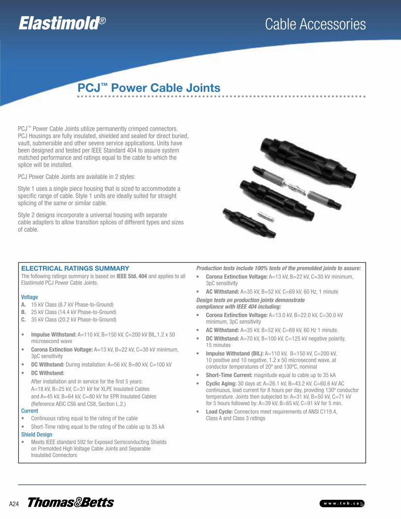
PCJ™ Power Cable Joints utilize permanently crimped connectors. PCJ Housings are fully in sulated, shielded and sealed for direct buried,vault, submersible and other severe service applications. Units havebeen designed and tested per IEEE Standard 404 to assure systemmatched performance and ratings equal to the cable to which thesplice will be installed.
PCJ Power Cable Joints are available in 2 styles:
Style 1 uses a single piece housing that is sized to accommodate aspecific range of cable. Style 1 units are ideally suited for straightsplicing of the same or similar cable.
Style 2 designs incorporate a universal housing with separatecable adapters to allow transition splices of different types and sizesof cable.
PCJ™ Power Cable Joints
ELECTRICAL RATINGS SUMMARYThe following ratings summary is based on IEEE Std. 404 and applies to allElastimold PCJ Power Cable Joints.
VoltageA. 15 kV Class (8.7 kV Phase-to-Ground)B. 25 kV Class (14.4 kV Phase-to-Ground)C. 35 kV Class (20.2 kV Phase-to-Ground)
• Impulse Withstand: A=110 kV, B=150 kV, C=200 kV BIL,1.2 x 50microsecond wave
• Corona Extinction Voltage: A=13 kV, B=22 kV, C=30 kV minimum,3pC sensitivity
• DC Withstand: During installation: A=56 kV, B=80 kV, C=100 kV
• DC Withstand:After installation and in service for the first 5 years: A=18 kV, B=25 kV, C=31 kV for XLPE Insulated Cables and A=45 kV, B=64 kV, C=80 kV for EPR Insulated Cables(Reference AEIC CS6 and CS8, Section L.2.)
Current• Continuous rating equal to the rating of the cable
• Short-Time rating equal to the rating of the cable up to 35 kAShield Design• Meets IEEE standard 592 for Exposed Semiconducting Shields
on Premolded High Voltage Cable Joints and SeparableInsulated Connectors
Production tests include 100% tests of the premolded joints to assure:• Corona Extinction Voltage: A=13 kV, B=22 kV, C=30 kV minimum,
3pC sensitivity
• AC Withstand: A=35 kV, B=52 kV, C=69 kV, 60 Hz, 1 minute
Design tests on production joints demonstratecompliance with IEEE 404 including:• Corona Extinction Voltage: A=13.0 kV, B=22.0 kV, C=30.0 kV
minimum, 3pC sensitivity
• AC Withstand: A=35 kV, B=52 kV, C=69 kV, 60 Hz 1 minute.
• DC Withstand: A=70 kV, B=100 kV, C=125 kV negative polarity,15 minutes
• Impulse Withstand (BIL): A=110 kV, B=150 kV, C=200 kV,10 positive and 10 negative, 1.2 x 50 microsecond wave, atconductor temperatures of 20º and 130ºC, nominal
• Short-Time Current: magnitude equal to cable up to 35 kA
• Cyclic Aging: 30 days at: A=26.1 kV, B=43.2 kV, C=60.6 kV AC continuous, load current for 8 hours per day, providing 130º conductor temperature. Joints then subjected to: A=31 kV, B=50 kV, C=71 kV for 5 hours followed by: A=39 kV, B=65 kV, C=91 kV for 5 min.
• Load Cycle: Connectors meet require ments of ANSI C119.4,Class A and Class 3 ratings

Elastimold® Cable Accessories
A25w w w . t n b . c a
1 5 P C J 1 W 1 X
Style 1Cat. No.
A B
(in.) (in.)
15PCJ1FX 10-1/4 1-3/4
15PCJ1GX 10-1/4 1-3/4
25PCJ1GX 14-3/8 2-7/16
15/25/35PCJ1HX 14-3/8 2-7/16
15/25/35PCJ1JX 14-3/8 2-7/16
15/25/35PCJ1KX 14-3/8 2-25/32
15/25/35PCJ1LX 14-3/8 2-25/32
15/25PCJ1LMX 14-3/8 2-25/32
15/25/35PCJ1MX 14-3/8 2-25/32
15/25/35PCJ1NX 15-3/4 3-3/16
15/25/35PCJ1PX 15-3/4 3-3/16
15/25/35PCJ1QX 15-3/4 3-3/16
Voltage
Class
Power
Cable
Joint
Insulation
Diameter
Conductor
Size Code
Style
Conductor
1 - Style 12 - Style 2
1 - Aluminum2 - Copper
W SIZING INFORMATION AND SELECTIONUse Table W8 for 15PCJUse Table W9 for 25PCJUse Table W10 for 35PCJ
X SIZING INFORMATION AND SELECTIONUse Table X7 for 15PCJ, 25PCJ and 35PCJ
DIMENSIONAL DATA
Style 2Cat. No.
A B
(in.) (in.)
15PCJ2FX 16-3/8 2-25/32
15/25PCJ2GX 16-3/8 2-25/32
15/25/35PCJ2HX 16-3/8 2-25/32
15/25/35PCJ2JX 16-3/8 2-25/32
15/25/35PCJ2KX 21 3-3/4
15/25/35PCJ2LX 21 3-3/4
15/25/35PCJ2MX 21 3-3/4
15/25/35PCJ2NX 21 3-3/4
15/25/35PCJ2PX 21 3-3/4
15/25/35PCJ2QX 21 3-3/4
DIMENSION BOUTSIDE DIA.
DIMENSION AOVERALL LENGTH
Description VoltageClass
ELASTIMOLDCat. No.
Notes
Power Cable Joint
Style 1
15 kV15 kV25 kV25 kV35 kV35 kV
15PCJ1W1X15PCJ1W2X25PCJ1W1X25PCJ1W2X35PCJ1W1X35PCJ1W2X
N1N2N1N2N1N2
Power Cable Joint
Style 2
15 kV15 kV25 kV25 kV35 kV35 kV
15PCJ2W1X15PCJ2W2X25PCJ2W1X25PCJ2W2X35PCJ2W1X35PCJ2W2X
N1N2N1N2N1N2
N1. Kit includes aluminum compression connector suitable for splicing aluminum conductor to aluminum conductor or aluminum conductor to copper conductor. An all-copper connector is required for copper-to-copper connections.
N2. Kit includes copper compression connector suitable for splicing copper conductors to copper conductor only. DO NOT use copper connectors on aluminum conductors.
Refer to the W and X tables on pages A39 to A41 for sizing to cable insulation diameter and conductor size. For cable shield adapters and jacket seals, see page A30.
ORDERING INFORMATION
PCJ Style 2with universal housing and separate cable adapters
that can be varied with the cable application.
PCJ™ Power Cable Joints
PCJ Style 1with single-piece housing

Elastimold® Cable Accessories
A26 w w w . t n b . c a
The following ratings summary is based on IEEE Std. 48 and applies to all the terminations on pages A26 thru A29. Elastimold terminations are designed for useon three-phase systems, either 3-wire or 4-wire and the single-phase laterals of thesesystems.
Voltage Ratings15 kV Class9.5 kV Phase-to-Ground110 kV BIL 1.2 x 50 microsecond waveAC Withstand:
50 kV 1 min. – dry35 kV 6 hr. – dry45 kV 10 sec. – wet
13 kV Corona Extinction25 kV Class16 kV Phase-to-Ground150 kV BIL 1.2 x 50 microsecond waveAC Withstand:
65 kV 1 min. – dry55 kV 6 hr. – dry60 kV 10 sec. – wet
21.5 kV Corona Extinction35 kV Class22 kV Phase-to-Ground200 kV BIL 1.2 x 50 microsecond waveAC Withstand:
90 kV 1 min. – dry75 kV 6 hr. – dry80 kV 10 sec. – wet
30 kV Corona Extinction
Electrical RatingsSummary
Cable Terminations
Elastimold® cable terminations are available in single piece or modulardesigns. Terminators allow connection and transition from shielded,underground cable to bare overhead conductors and live-frontequipment. Units are designed and rated per IEEE Standard 48 forriser pole, padmount, indoor and outdoor applications. PCT1, PCT2,16THG and 35MTG terminators provide sufficient creep, strike andweather sealing for class 1 outdoor service. PCT1 and PCT2 alsoinclude an integral cable jacket seal.
The 35MTGI terminators and 35MSC stress cones are rated for class2 and class 3 indoor service respectively. Optional mounting brackets,aerial lugs and equipment connectors are available as required.
TERMINATIONS
SINGLE PIECE TERMINATORS STRESS CONE MODULAR TERMINATORS
BRACKETS
PCT-1 PCT-2 16THG 16THGS 35MSC 35MSCI 35MTGI 35MTG
PB-1 16TB2 35MTB 1535AFB

Elastimold® Cable Accessories
A27w w w . t n b . c a
Cable Terminations
Refer to the W and X tables on pages A39 to A41 for sizing to cable insulation diameter and conductor size.For cable shield adapters and jacket seals, see page A30.
Illustration(not to scale) Description
VoltageClass
ELASTIMOLDCat. No. Notes
Single-PieceTerminator(Class 1)
15 kV
25 kV
PCT1-1X-4Use Table X9PCT2-1X-4Use Table X9
N12, 14,15, 22N12, 14,N15, 23
Housingonly
15 kV25 kV
PCT1-4PCT2-4
N13,22N13,23
Single-PieceTerminator(Class 1)
15/25 kV 16THG-W0X-4Use Tables W12 and X8
N2, 1415
Housingonly 15/25 kV 16THGH-W
Use Table W12
Single-PieceTerminator
for solidconductor only
(Class 1)
15/25 kV 16THGS-WXUse Tables W12 and X4 N3
Stress Cone(Class 3) ALL 35MSC-W
Use Table W11 N17
Stress Conew/Grd. Strap ALL 35MSCI-W
Use Table W11 N17
Modulesonly ALL 35MG-W
Use Table W13 N11, 16
ModularTerminator(Class 1)
15 kV
25 kV
35 kV
35MTG-WX-4-CAUse Tables W13 and X335MTG-WX-8-CAUse Tables W13 and X335MTG-WX-10-CAUse Tables W13 and X3
N2, 11
N2, 5, 11
N2, 6, 11
ModularTerminator(Class 2)w/o Rain
Cap
15 kV
25 kV
35 kV
35MTGI-W-4Use Table W1335MTGI-W-6Use Table W1335MTGI-W-8Use Table W13
N11
N11
N7, 11
Rod Contactfor PCT 15/25 kV 00700X
Use Table X9N1, 14,15
Rod Contactfor 16THG 15/25 kV 16TCA-X
Use Table X8 N2, 8
Solid ConductorPackage
for 16THGS15/25 kV 16CAS-X
Use Table X4 N3, 9
3/4 in.-16Threaded
Rod for MTGALL 35MTGA-WX-1
Use Tables W13 and X3N2, 10, 1118, 25
1 in.-14 ThreadedRod for MTG ALL 35MTGA-WX-2
Use Tables W13 and X3AN2, 10, 1119, 25
Two-Hole Spadefor MTG ALL 35MTGA-WX-3
Use Tables W13 and X3N4, 10, 1120, 25
Two-Hole Spadefor PCT ALL 01000X
Use Table X9 N1
One-Hole Spadefor PCT ALL 01100X
Use Table X9 N1
Universal Rodfor MTG ALL 35MTGA-WX-4
Use Tables W13 and X3N2, 10, 1121, 25
Aerial Lugsfor MTG
Threaded Rod(Two-hole spade
or bare wire)
ALL 35AL-A N10, 24
N1. Use with PCT1 or PCT2 Terminators.N2. Includes contact rod, ground strap and rain cap.N3. Includes crimp ring, ground strap and rain cap.N4. Includes spade contact, ground strap and rain cap.N5. For KA thru PB sizes use 35MTG-WX-6-CA.N6. For KA thru PB sizes use 35MTG-WX-8-CA.N7. For KA thru PB sizes use 35MTGI-W-6.N8. Use with 16THG Terminators.N9. Use with 16THGS Terminators.N10.Use with 35MTG Terminators.N11.Refer to page A26 for detailed ordering instructions.N12.Includes rod contact as standard. Specify suffix “-3” in place of “-4” for two-hole spade lug. Specify suffix “-5”
in place of “-4” for one-hole spade lug.N13.Specify suffix “-3” or “-5” in place of “-4” for two-hole spade lug housing or one- hole spade style housing.N14.Use 1X for an aluminum rod contact for aluminum conductors only.N15.Substitute 0X for 1X for a universal aluminum rod contact for aluminum or copper conductors.N16.Available in sizes from GA thru PB and are supplied qty. 2 per package.N17.Available in sizes EB thru PB.N18.For conductors from 1/0 thru 350 kcmil.N19.For conductors from 400 kcmil thru 1000 kcmil.N20.For conductors from #2 to 1000 kcmil.N21.For conductors from #6 thru 4/0.N22.Use for insulation dia. range from .640 in. thru 1.070 in.N23.Use for insulation dia. range from .830 in. thru 1.180 in.N24.Select symbol for “A” from aerial lug ordering information on page A28.N25.W13 Table provides sizing for rain cap. X10 Table provides sizing for connectors.

Elastimold® Cable Accessories
A28 w w w . t n b . c a
Cable Terminations
35MTG - W X - N - C A
Use Table W13, below
ORDERING INSTRUCTIONS FOR MODULAR TERMINATORS
I - IndoorBlank = Outdoor
Use Table X3 or Table X3A
RecommendedNumber of Modules
NOTE: Applicable table and available sizes depend upon connector style. Reference Connector Style Selection Chart and notes A through D.
Connector Style Selection Chart
Description Available forConductor
Sizes
Symbol Notes
3/4 in.-16Threaded
Rod
1/0 thru350 kcmil
-1 A
1 in.-14Threaded
Rod
400 thru1000 kcmil
-2 B
2-HoleSpade
#2 thru1000 kcmil
-3 C
UniversalRod
#6 thru 4/0 -4 D
Aerial Lugs forThreaded RodConnectors Only
Type Connector Symbol
Bare Wire 3/4 in.-16Rod
-11
2-Hole Spade 3/4 in.-16Rod
-12
Bare Wire 1 in-14Rod
-21
2-Hole Spade 1 in-14Rod
-22
NOTES:A. Available for 1/0 through 350 conductor sizes only. Use Table X3 for size selection.B. Available for 400 through 1000 conductor sizes only. Use Table X3A for size selection.C. Available for #2 through 1000 conductor sizes only. Use Table X3 for size selection.D. Available for #6 through 4/0 conductor sizes only. Use Table X3 for size selection.
Table W13USE FORFOLLOWINGPRODUCTS35MTG35MTGI
Cable insulationDiameter in (in.)
Symbolfor WMin. Max.
0.775 0.885 GA
0.825 0.935 GAB
0.875 0.985 GB
0.930 1.040 GH
0.980 1.115 HA
1.040 1.175 HAB
1.095 1.240 HB
1.160 1.305 HJ
1.220 1.375 JA
1.285 1.395 JAB
1.355 1.520 JB
1.485 1.595 KA
1.530 1.640 KAB
1.575 1.685 KB
1.665 1.785 PA
1.755 1.875 PB
Table X3AUSE FORFOLLOWINGPRODUCTS35MTG
FOR USEWITH STYLE-2CONNECTORSONLY.
SEE NOTES BFOR APPLICATIONINFORMATION
ConductorSIZE AWGor kcmil
Symbol for X
Strand./Compr.
Compt./Solid
400 400 –
450 450 400
500 500 450
550 550 500
600 600 500
650-700 650 550
750 750 600
800 750 650
1000 1000 –
Table X3USE FORFOLLOWINGPRODUCTS35MTG
FOR USE WITHSTYLE-1,-3, and -4CONNECTORSONLY.
SEE NOTES A,C, and D FORAPPLICATIONINFORMATION
ConductorSIZE AWGor kcmil
Symbol for X
Strand./Compr.
Compt./Solid
#6 5 –
#5 4 5
#4 3 4
#3 2 3
#2 1 2
#1 0 1
1/0 10 0
2/0 20 10
3/0 30 20
4/0 40 30
250 250 40
300 300 250
350 350 300
400 400 350
450 450 –
500 500 400
550 550 450
600 600 500
650 650 550
700 750 600
750 750 650
800 800 750
900 900 800
1000 1000 900
GA-JB KA-PB
15 kV 4 4
25 kV 8 8
35 kV 10 10

Elastimold® Cable Accessories
A29w w w . t n b . c a
Cable Terminations
Illustration(not to scale) Description
VoltageClass
ELASTIMOLDCat. No. Notes
PCTPositioning
BracketALL PB-1 N1, 12
16THG Bracket ALL 16TB-2 N6
Bracketfor crossarm
16THGALL 16TB-3 N6
Bracketfor riser pole
mounting16THG
ALL 16TB-4 N6
Bracketfor tri-mounting
16THGALL 16TB-5 N6
KELLUMSGRIP
Bracket
ALLALLALLALL
35MTB1-A35MTB1-B35MTB1-C35MTB1-D
N1, 2, 6, 7N1, 3, 6, 7N1, 4, 6, 7N1, 5, 6, 7
KELLUMSBracket
for crossarmmounting
ALLALLALLALL
35MTB3-A35MTB3-B35MTB3-C35MTB3-D
N1, 2, 6, 7N1, 3, 6, 7N1, 4, 6, 7N1, 5, 6, 7
Bracket(for riser pole
mounting)
ALLALLALLALL
35MTB4-A35MTB4-B35MTB4-C35MTB4-D
N1, 2, 6, 7N1, 3, 6, 7N1, 4, 6, 7N1, 5, 6, 7
KELLUMSBracket
for tri-mounting
ALLALLALLALL
35MTB5-A35MTB5-B35MTB5-C35MTB5-D
N1, 2, 6, 7N1, 3, 6, 7N1, 4, 6, 7N1, 5, 6, 7
ALUMA FORMBracket ALL 1535AFB-1 N1, 6 ,7, 13
ALUMA FORMBracket
for Crossarmmounting
ALL 1535AFB-3 N1, 6, 7, 13
ALUMA FORMBracket
for riser-polemounting
ALL 1535AFB-4 N1, 6, 7, 13
ALUMA FORMBracket
for tri-mountingALL 1535AFB-5 N1, 6, 7, 13
N1. Use with PCT-1 or PCT-2 Terminators.N2. Fits overall cable O.D. from 1.195 in. to 1.625 in.N3. Fits overall cable O.D. from 0.925 in. to 1.335 in.N4. Fits overall cable O.D. from 0.890 in. to 1.185 in.N5. Fits overall cable O.D. from 1.500 in. to 2.000 in.N6. Use with 16THG and 16THGS Terminators.N7. Use with MTG, MTG1 and MSC Terminators.N8. For conductors from 1/0 thru 350 kcmil.N9. For conductors from 400 kcmil thru 1000 kcmil.N10.For conductors from #2 to 1000 kcmil.N11.For conductors from #6 thru 4/0.N12.Fits overall cable O.D. from 0.750 in. to 1.625 in.N13.Fits overall cable O.D. from 0.750 in. to 2.000 in.
TERMINATIONS
Refer to the W and X tables on pages A39 to A41 for sizing to cable insulation diameter and conductor size.For cable shield adapters and jacket seals, see page A30.

Elastimold® Cable Accessories
A30 w w w . t n b . c a
Shield Adapters, Sealing and Grounding
Elastimold cable terminations are available in single piece or modular designs.Terminators allow connection and transition from shielded, underground cable to bareoverhead conductors and live-front equipment. Units are designed and rated per IEEEStandard 48 for riser pole, padmount, indoor and outdoor applications. PCT1, PCT2,16THG and 35MTG terminators provide sufficient creep, strike and weather sealing forclass 1 outdoor service. PCT1 and PCT2 also include an integral cable jacket seal.
The 35MTGI terminators and 35MSC stress cones are rated for class 2 and class 3 indoorservice respectively. Optional mounting brackets, aerial lugs and equipment connectorsare available as required.
CABLE ENTRANCE DETAIL
600/200ECS
INSULATIONEPDM RUBBER
MOLDED SHIELDCONDUCTIVE EPDM RUBBER
600/200ECSG1-2 21MA 20MA 600/200
ECSG2-2600/200ECSG3 10 TL 10 TL
NONEREQUIRED
CONDUCTOR
INSULATION
EXTRUDED SHIELD
CONCENTRICNEUTRAL WIRES
OUTER JACKET
CABLESHIELDTYPES
JACKETEDCONCENTRICNEUTRALCABLE
CONCENTRICNEUTRALCABLE
DRAINWIRE
SHIELDEDCABLE
COPPERTAPE
SHIELDEDCABLE
LEADJACKETEDCABLE
UNSHIELDCABLE
CONDUCTOR
INSULATION
EXTRUDED SHIELD
CONCENTRICNEUTRAL WIRES
CONDUCTOR
INSULATION
EXTRUDED SHIELD
DRAIN WIRES
OUTER JACKET
CONDUCTOR
INSULATION
EXTRUDED SHIELD
COPPER SHIELD
OUTER JACKET
CONDUCTOR
INSULATION
EXTRUDED SHIELD
OUTER JACKET
CONDUCTOR
INSULATION
EXTRUDEDCONDUCTIVEJACKET
DRAIN WIRES
20MA10TL 21MA ECS
CABLE SHIELD ADAPTERS
CableInsulation Dia.
10TL 20MA 21MA
(in.) (in.) (in.)
min. 0.495 0.530 0.530
max. 1.875 1.780 1.780
JACKET SEALS
JacketO.D.
200ECS 600ECS
(in.) (in.)
min. 0.80 1.28
max. 1.50 2.30

Elastimold® Cable Accessories
A31w w w . t n b . c a
Shield Adapters, Sealing and Grounding
N1. To order the kits as separate items, use the Cat. Nos shown in the table.Example: To order a cold shrinkable tube as a separate item, use the Cat. No. 200ECS.To order the kits as components of other items, add the suffix to the end of the Cat. No. Example: To order a cold shrinkable jacket seal as a component of an elbow kit, use the Cat. No. 166LR-A5200-S.
N2. Only use this suffix with Cat. Nos that designate a “W” housing size. Sizing the main component will also size the suffix adapter.
N3. Size range 0.80 in. to 1.50 in. jacket diameters. Maximum installed diameter is approx. 02 in.N4. Size range 1.28 in. to 2.30 in. jacket diameters. Maximum installed diameter is approx. 2.75 in.N5. Voltage rating equal to Elastimold product being used.N6. Copper rod size is no. 6 for sizes FA thru HA and no. 2 for sizes HAB thru JB.N7. Braid is equivalent to no. 6 copper rod for sizes FA thru HA and no. 2 copper rod for sizes HAB thru JB.
Illustration(not to scale) Description ELASTIMOLD
Cat. No. Suffix Notes
Cold ShrinkableJacket Seal 200ECS -S N1, 3
Cold ShrinkableJacket Seal 600ECS -S N1, 4
Metallic TapeShield Adapter
20MA-WUse Table W14for sizing
-0MA N1, 2, 5, 6
Wire ShieldAdapter
21MA-WUse Table W14for sizing
-1MA N1, 2, 5, 6
ShieldAdapter
10TL-WUse Table W15for sizing
-TL N1, 2
Cold Shrinkable Sealw/ Copper Rod andCrimp Connector
200ECSG1-2 -SG1 N1 ,3 ,5, 6
Cold Shrinkable Sealw/ Copper Rod andCrimp Connector
600ECSG1-2 -SG1 N1, 4, 5, 6
Cold Shrinkable Sealw/ Copper Rod and
Constant ForceSpring
200ECSG2-2 -SG2 N1, 3, 5, 6
Cold Shrinkable Sealw/ Copper Rod and
Constant ForceSpring
600ECSG2-2 -SG2 N1, 4, 5, 6
Cold Shrinkable Sealw/ Copper Braid and
Constant ForceSpring
200ECSG3 -SG3 N1, 3, 5, 7
Cold Shrinkable Sealw/ Copper Braid and
Constant ForceSpring
600ECSG3 -SG3 N1, 4, 5, 7
Table W14USE FOR20MA21MA
Insulation
Symbolfor W
(in.)
Min. Max.
0.530 0.680 E
0.640 0.820 F
0.760 0.950 G
0.850 1.050 H
0.980 1.180 J
1.090 1.310 K
1.180 1.465 L
1.370 1.630 M
1.515 1.780 N
Table W15USE FOR10TL
Insulation
Symbolfor W
(in.)
Min. Max.
0.495 0.585 EB
0.525 0.635 EF
0.575 0.585 FA
0.625 0.735 FAB
0.675 0.785 FB
0.725 0.835 FG
0.775 0.885 GA
0.825 0.935 GAB
0.875 0.985 GB
0.930 1.040 GH
0.980 1.115 HA
1.040 1.175 HAB
1.095 1.240 HB
1.160 1.305 HJ
1.220 1.375 JA
1.285 1.395 JAB
1.355 1.520 JB
1.485 1.595 KA
1.530 1.640 KAB
1.575 1.685 KB
1.755 1.875 PB
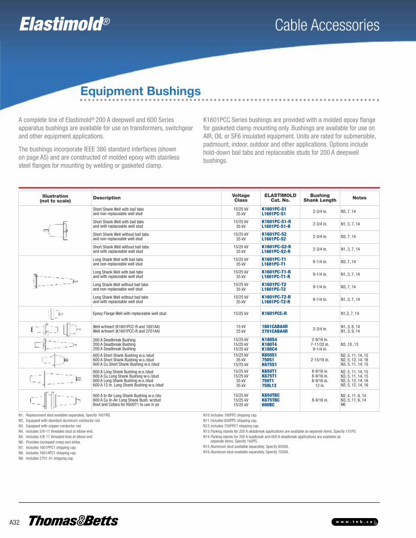
Elastimold® Cable Accessories
A32 w w w . t n b . c a
Equipment Bushings
A complete line of Elastimold® 200 A deep well and 600 Seriesapparatus bushings are available for use on transformers, switchgearand other equipment applications.
The bushings incorporate IEEE 386 standard interfaces (shown on page A5) and are constructed of molded epoxy with stainless steel flanges for mounting by welding or gasketed clamp.
K1601PCC Series bushings are provided with a molded epoxy flangefor gasketed clamp mounting only. Bushings are available for use onAIR, OIL or SF6 insulated equipment. Units are rated for submersible,padmount, indoor, outdoor and other applications. Options includehold-down bail tabs and replaceable studs for 200 A deepwell bushings.
N1. Replacement stud available separately. Specify 1601RS.N2. Equipped with standard aluminum conductor rod.N3. Equipped with copper conductor rod.N4. Includes 5/8-11 threaded stud at elbow end.N5. Includes 5/8-11 threaded hole at elbow end.N6. Provides increased creep and strike.N7. Includes 1601PPC1 shipping cap.N8. Includes 1601APC1 shipping cap.N9. Includes 2701-41 shipping cap.
N10.Includes 180PPC shipping cap.N11.Includes 650PPC shipping cap.N12.Includes 750PPC1 shipping cap.N13.Parking stands for 200 A deadbreak applications are available as separate items. Specify 151PS.N14.Parking stands for 200 A loadbreak and 600 A deadbreak applications are available as
separate items. Specify 160PS.N15.Aluminum stud available separately. Specify 650SA.N16.Aluminum stud available separately. Specify 750SA.
Illustration(not to scale)
Description VoltageClass
ELASTIMOLDCat. No.
BushingShank Length Notes
Short Shank Well with bail tabsand non-replaceable well stud
15/25 kV35 kV
K1601PC-S1L1601PC-S1 2-3/4 in. N3, 7, 14
Short Shank Well with bail tabsand with replaceable well stud
15/25 kV35 kV
K1601PC-S1-RL1601PC-S1-R 2-3/4 in. N1, 3, 7, 14
Short Shank Well without bail tabsand non-replaceable well stud
15/25 kV35 kV
K1601PC-S2L1601PC-S2 2-3/4 in. N3, 7, 14
Short Shank Well without bail tabsand with replaceable well stud
15/25 kV35 kV
K1601PC-S2-RL1601PC-S2-R 2-3/4 in. N1, 3, 7, 14
Long Shank Well with bail tabsand non-replaceable well stud
15/25 kV35 kV
K1601PC-T1L1601PC-T1 9-1/4 in. N3, 7, 14
Long Shank Well with bail tabsand with replaceable well stud
15/25 kV35 kV
K1601PC-T1-RL1601PC-T1-R 9-1/4 in. N1, 3, 7, 14
Long Shank Well without bail tabsand non-replaceable well stud
15/25 kV35 kV
K1601PC-T2L1601PC-T2 9-1/4 in. N3, 7, 14
Long Shank Well without bail tabsand with replaceable well stud
15/25 kV35 kV
K1601PC-T2-RL1601PC-T2-R 9-1/4 in. N1, 3, 7, 14
Epoxy Flange Well with replaceable well stud 15/25 kV K1601PCC-R N1,3, 7, 14
Well w/Insert (K1601PCC-R and 1601A4)Well w/Insert (K1601PCC-R and 2701A4)
15 kV25 kV
1601CABA4R2701CABA4R 2-3/4 in. N1, 3, 8, 14
N1, 3, 9, 14
200 A Deadbreak Bushing200 A Deadbreak Bushing200 A Deadbreak Bushing
15/25 kV15/25 kV15/25 kV
K180S4K180T4K180C4
2-9/16 in.7-11/32 in.9-1/4 in.
N3 ,10 ,13
600 A Short Shank Bushing w.o./stud600 A Short Shank Bushing w.o./stud600 A Cu Short Shank Bushing w.o./stud
15/25 kV35 kV
15/25 kV
K650S1750S1K675S1
2-15/16 in.N2, 5, 11, 14, 15N2, 5, 12, 14, 16N3, 5, 11, 14, 15
600 A Long Shank Bushing w.o./stud600 A Cu Long Shank Bushing w.o./stud600 A Long Shank Bushing w.o./stud600 A 12 in. Long Shank Bushing w.o./stud
15/25 kV15/25 kV
35 kV35 kV
K650T1K675T1750T1750L12
8-9/16 in.8-9/16 in.8-9/16 in.
12 in.
N2, 5, 11, 14, 15N3, 5, 11, 14, 15N2, 5, 12, 14, 16N2, 5, 12, 14, 16
600 A In-Air Long Shank Bushing w.o./stu600 A Cu In-Air Long Shank Bush. w/studBoot and Collars for K600T1 to use in air
15/25 kV15/25 kV15/25 kV
K650TBCK675TBC600BC
8-9/16 in.N2, 4, 11, 6, 14N3, 5, 11, 6, 14N6

Elastimold® Cable Accessories
A33w w w . t n b . c a
How to Specify Size-Sensitive Products
Ordering ExamplesAEICTo complete the information required to order a K655LR-W0X elbowfor use on standard AEIC 1000 kcmil compressed strandingaluminum 25 kV cable with .260 inch thick insulation wall:
A. Determine that the insulation diameter (for AEIC cable inthe table on pages A35-A37) is 1.645 – 1.770 in.
B. For this elbow, the Cat. No. selection chart on page A13 indicates to use table W7 for elbow sizing and table X6 for connector sizing.
C. From table W7 the symbol for W is N.D.From table X6 the symbol for X is 410.E. The completed Cat. No. therefore is K655LR-N0410.
ICEATo complete the information required to order a K655LR-W0X elbowfor use on standard ICEA 1000 kcmil compressed stranding aluminum25 kV cable with .260 inch thick insulation wall:
A. Determine that the insulation diameter (for ICEA cable inthe table on pages A35-A37) is 1.645 – 1.740 in.
B. For this elbow, the Cat. No. selection chart on page A13indicates to use table W7 for elbow sizing and table X6 forconnector sizing.
C. From table W7 the symbol for W is N.D.From table X6 the symbol for X is 410.E. The completed Cat. No. therefore is K655LR-N0410.
PN
Elastimold Elbows, cable joints and terminations are designed for application on XLP, EPR and other solid dielectric insulated power cables.These components are constructed of molded elastomer and rely on an interference fit with the cable insulation diameter in order to maintainproper dielectric strength, creep path integrity and a water seal. Elastimold components are available in a wide range of sizes in order toaccommodate a variety of cable insulation diameters.
Selection of size-sensitive components requires determining the cable insulation diameter.This can be done in several ways:
A. Refer to the cable manufacturer’s spec sheet for dimensions.B. Measure the cable.C. If the cable conforms to AEIC or ICEA standards and is:
1. 15 kV, 175 mil wall thickness, use the table on page A35.2. 15 kV, 220 mil wall thickness, use the table on page A36.3. 25 kV, 260 mil wall thickness, use the table on page A36.4. 35 kV, 345 mil wall thickness, use the table on page A37.
After the cable insulation diameter minimum and maximum has been determined:
1. Locate the W table indicated in the Cat. No. selection chart.2. Complete the ordering information by selecting and inserting the symbol (given in the W table) into the Cat. No.
— — — -WX- ——
“W”CABLE
INSULATIONDIAMETER
Determines Size of Molded Rubber Part
“W”INSULATIONDIAMETER
INSULATION DIAMETER SELECTION GUIDE

Elastimold® Cable Accessories
A34 w w w . t n b . c a
How to Specify Size-Sensitive Products
Elastimold® elbows, cable joints and terminations are furnished with crimp stylecable connectors. As standard, these connectors are constructed with a tin-plated aluminum barrel filled with an oxide inhibitor. Most aluminum barrel connectors areuniversal and are designed for use on either aluminum or copper conductor cable.
When specified, all copper crimp style connectors can be furnished. These connectors are only for use on copper conductor cable and are not for use with aluminum conductor cables. Bi-metallic connectors are constructed with a coppertop and an aluminum barrel. Bi-metal connectors can be used on either aluminum orcopper conductor cable and are furnished as standard with 200 A Loadbreak Elbows,200 A Deadbreak Elbows, and PCT, 16 THG or MTG terminators with rod connectors.
Aluminum connectors used in PCJ Cable Joints are rated as follows:• Aluminum conductor to aluminum conductor, cable rated• Aluminum conductor to copper conductor, cable rated equal to the
aluminum cable
Copper connectors used in PCJ Cable Joints are rated as follows: • Copper conductor to copper conductor, cable rated
Selection and ordering the proper crimp connector requires determining information relative to the cable conductor as follows:A. Conductor size in AWG or kcmilB. Conductor type (stranded, compressed, compact or solid)C. Conductor material (aluminum or copper)
After the cable conductor information has been determined:1. Locate the X table indicated in the Cat. No. selection chart.2. Complete the ordering information by selecting and inserting the symbol
(given in the X table) into the Cat. No.
See the Ordering Example on page A33 for further information.
PN — — — -WX- ——
“X”CABLE
CONDUCTOR
Determines Crimp Connector Size
“X”CABLE
CONDUCTOR
PN——— -WX-——
CABLE SHIELDAND JACKET
Determines RequiredAccessories (if any)• Cable Shield Adaptors• Cable Grounding Kits• Cable Jacket Seal
“SUFFIX”
Reference Pages A30 and A31for application, selection and
ordering information.
CONNECTOR SELECTION GUIDE

Elastimold® Cable Accessories
A35w w w . t n b . c a
AEIC and ICEA Cable InsulationDiameter15 kV 100% – 175 mil Insulation (0.175 in.)15 kV 133% – 220 mil Insulation (0.220 in.)25 kV 100% – 260 mil Insulation (0.260 in.)35 kV 100% – 345 mil Insulation (0.345 in.)
AEIC CS8-06Specification for Extruded Dielectric,
Shielded Power Cable Rated 5 - 46 kV
AEIC-Calulated Diameters - Solid and Compressed Stranding from Tables C-4 and C-6 and Compact Stranding from Tables C-5 and C-7
ANSI/ICEA S-94-649-2004 and S-97-682-2000Standard for Concentric Neutral Cables and
Utility Shielded Power Cables Rated 5 - 46 kVICEA-Concentric Stranding Table C-3, Compressed Stranding
Table C-4, Compact Stranding Table C-5
ICEA Abbreviated, for additional cables please refer to the standard.
WALL
W = Insulation Diameter (Conductor + 2 X Conductor Shield + 2 X wall)
15 kV Cable (100% level, 175 mil)
Aluminumand CopperConductor
Size
IndustryStandard
Solid Conductor Stranded Conductor Compressed Conductor Compact Conductor
Diameter (in.)Over Insulation
Diameter (in.)Over Insulation
Diameter (in.)Over Insulation
Diameter (in.)Over Insulation
Min. Max. Min. Max. Min. Max. Min. Max.
#2AEIC 0.610 0.700 – – 0.635 0.725 0.620 0.710
ICEA 0.610 0.695 0.645 0.730 0.635 0.720 0.620 0.705
#1AEIC 0.645 0.730 – – 0.675 0.765 0.655 0.740
ICEA 0.645 0.725 0.685 0.770 0.675 0.760 0.655 0.735
1/0AEIC 0.680 0.770 – – 0.715 0.805 0.690 0.775
ICEA 0.680 0.760 0.725 0.810 0.715 0.800 0.690 0.775
2/0AEIC – – – – 0.760 0.850 0.730 0.815
ICEA – – 0.775 0.855 0.760 0.845 0.730 0.815
3/0AEIC – – – – 0.810 0.900 0.775 0.865
ICEA – – 0.825 0.905 0.810 0.895 0.775 0.860
4/0AEIC – – – – 0.865 0.955 0.830 0.915
ICEA – – 0.880 0.965 0.865 0.950 0.830 0.910
250AEIC – – – – – – – –
ICEA – – 0.935 1.020 0.920 1.005 0.880 0.965
350AEIC – – – – 1.025 1.115 0.980 1.065
ICEA – – 1.045 1.130 1.025 1.110 0.980 1.065
500AEIC – – – – 1.150 1.245 1.100 1.185
ICEA – – 1.175 1.260 1.150 1.235 1.100 1.185
750AEIC – – – – 1.340 1.440 1.280 1.370
ICEA – – 1.370 1.455 1.340 1.425 1.280 1.365
1000AEIC – – – – 1.485 1.590 1.430 1.520
ICEA – – 1.520 1.610 1.485 1.575 1.430 1.515
ICEA NOTE: Diameters specified in the above table are different than specified by AEIC CS8-00.Consult your Regional Sales Office for proper selection of accessories. Diameters to be measured in accordance with 9.6.

Elastimold® Cable Accessories
A36 w w w . t n b . c a
AEIC and ICEA Cable Insulation Diameter
15 kV Cable (133% level, 220 mil)
Aluminumand CopperConductor
Size
Industry Standard
Solid Conductor Stranded Conductor Compressed Conductor Compact ConductorDiameter (in.)Over Insulation
Diameter (in.)Over Insulation
Diameter (in.)Over Insulation
Diameter (in.)Over Insulation
Min. Max. Min. Max. Min. Max. Min. Max.
#2AEIC 0.700 0.790 – – 0.725 0.815 0.710 0.800
ICEA 0.700 0.790 0.735 0.825 0.725 0.815 0.710 0.800
#1AEIC 0.735 0.820 – – 0.765 0.855 0.745 0.830
ICEA 0.735 0.820 0.775 0.865 0.765 0.855 0.745 0.830
1/0AEIC 0.770 0.860 – – 0.805 0.895 0.780 0.865
ICEA 0.770 0.855 0.815 0.905 0.805 0.895 0.780 0.865
2/0AEIC – – – – 0.850 0.940 0.820 0.905
ICEA – – 0.865 0.950 0.850 0.935 0.820 0.905
3/0AEIC – – – – 0.900 0.990 0.865 0.955
ICEA – – 0.915 1.000 0.900 0.985 0.865 0.955
4/0AEIC – – – – 0.955 1.045 0.920 1.005
ICEA – – 0.970 1.060 0.955 1.045 0.920 1.005
250AEIC – – – – – – – –
ICEA – – 1.025 1.115 1.010 1.100 0.970 1.060
350AEIC – – – – 1.115 1.205 1.070 1.155
ICEA – – 1.135 1.220 1.115 1.200 1.070 1.155
500AEIC – – – – 1.240 1.335 1.190 1.275
ICEA – – 1.265 1.355 1.240 1.330 1.190 1.275
750AEIC – – – – 1.430 1.530 1.370 1.460
ICEA – – 1.460 1.550 1.430 1.520 1.370 1.460
1000AEIC – – – – 1.575 1.680 1.520 1.610
ICEA – – 1.610 1.705 1.575 1.670 1.520 1.610
25 kV Cable (100% level, 260 mil)
Aluminumand CopperConductor
Size
Industry Standard
Solid Conductor Stranded Conductor Compressed Conductor Compact ConductorDiameter (in.)Over Insulation
Diameter (in.)Over Insulation
Diameter (in.)Over Insulation
Diameter (in.)Over Insulation
Min. Max. Min. Max. Min. Max. Min. Max.
#1AEIC 0.805 0.900 – – 0.835 0.935 0.815 0.910
ICEA 0.805 0.895 0.845 0.935 0.835 0.925 0.815 0.905
1/0AEIC 0.840 0.940 – – 0.875 0.975 0.850 0.945
ICEA 0.840 0.930 0.885 0.980 0.875 0.965 0.850 0.940
2/0AEIC – – – – 0.920 1.020 0.890 0.985
ICEA – – 0.935 1.025 0.920 1.010 0.890 0.980
3/0AEIC – – – – 0.970 1.070 0.935 1.035
ICEA – – 0.985 1.075 0.970 1.060 0.935 1.030
4/0AEIC – – – – 1.025 1.125 0.990 1.085
ICEA – – 1.040 1.135 1.025 1.115 0.990 1.080
250AEIC – – – – – – – –
ICEA – – 1.095 1.190 1.080 1.175 1.040 1.135
350AEIC – – – – 1.185 1.295 1.140 1.245
ICEA – – 1.205 1.295 1.185 1.275 1.140 1.230
500AEIC – – – – 1.310 1.425 1.260 1.365
ICEA – – 1.335 1.430 1.310 1.405 1.260 1.350
750AEIC – – – – 1.500 1.620 1.440 1.550
ICEA – – 1.530 1.625 1.500 1.595 1.440 1.535
1000AEIC – – – – 1.645 1.770 1.590 1.700
ICEA – – 1.680 1.775 1.645 1.740 1.590 1.685
ICEA NOTE: Diameters specified in the above table are different than specified by AEIC CS8-00.Consult your Regional Sales Office for proper selection of accessories. Diameters to be measured in accordance with 9.6.

Elastimold® Cable Accessories
A37w w w . t n b . c a
AEIC and ICEA Cable Insulation Diameter
35 kV Cable (100% level, 345 mil)
Aluminumand CopperConductor
SizeIndustryStandard
Solid Conductor Stranded Conductor Compressed Conductor Compact Conductor
Diameter (in.)Over Insulation
Diameter (in.)Over Insulation
Diameter (in.)Over Insulation
Diameter (in.)Over Insulation
Min. Max. Min. Max. Min. Max. Min. Max.
1/0AEIC 1.010 1.110 – – 1.045 1.145 1.020 1.115
ICEA 1.010 1.110 1.055 1.155 1.045 1.145 1.020 1.120
2/0AEIC – – – – 1.090 1.190 1.060 1.155
ICEA – – 1.105 1.200 1.090 1.190 1.060 1.160
3/0AEIC – – – – 1.140 1.240 1.105 1.205
ICEA – – 1.155 1.255 1.140 1.240 1.105 1.205
4/0AEIC – – – – 1.195 1.295 1.160 1.255
ICEA – – 1.210 1.310 1.195 1.295 1.160 1.260
250AEIC – – – – – – – –
ICEA – – 1.265 1.370 1.250 1.350 1.210 1.315
350AEIC – – – – 1.355 1.470 1.310 1.420
ICEA – – 1.375 1.475 1.355 1.455 1.310 1.410
500AEIC – – – – 1.480 1.600 1.430 1.540
ICEA – – 1.505 1.605 1.480 1.580 1.430 1.530
750AEIC – – – – 1.670 1.795 1.610 1.725
ICEA – – 1.700 1.800 1.670 1.770 1.610 1.710
1000AEIC – – – – 1.815 1.945 1.760 1.875
ICEA – – 1.850 1.955 1.815 1.920 1.760 1.865ICEA NOTE: Diameters specified in the above table are different than specified by AEIC CS8-00.Consult your Regional Sales Office for proper selection of accessories. Diameters to be measured in accordance with 9.6.
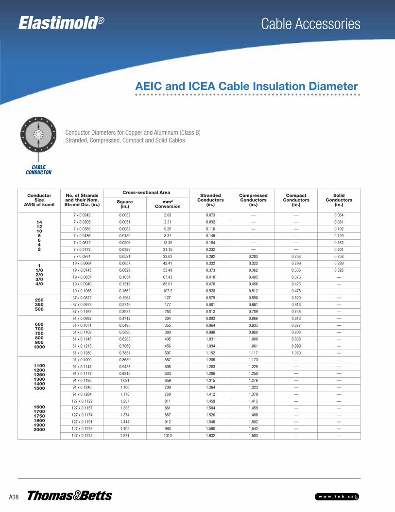
Elastimold® Cable Accessories
A38 w w w . t n b . c a
AEIC and ICEA Cable Insulation Diameter
Conductor Diameters for Copper and Aluminum (Class B)Stranded, Compressed, Compact and Solid Cables
CABLECONDUCTOR
ConductorSize
AWG of kcmil
No. of Strandsand their Nom.Strand Dia. (in.)
Cross-sectional AreaStranded
Conductors(in.)
CompressedConductors
(in.)
CompactConductors
(in.)
SolidConductors
(in.)Square(in.)
mm2
Conversion
1412108642
7 x 0.0242 0.0032 2.08 0.073 — — 0.064
7 x 0.0305 0.0051 3.31 0.092 — — 0.081
7 x 0.0385 0.0082 5.26 0.116 — — 0.102
7 x 0.0486 0.0130 8.37 0.146 — — 0.129
7 x 0.0612 0.0206 13.30 0.184 — — 0.162
7 x 0.0772 0.0328 21.15 0.232 — — 0.204
7 x 0.0974 0.0521 33.62 0.292 0.283 0.268 0.258
11/02/03/04/0
19 x 0.0664 0.0657 42.41 0.332 0.322 0.299 0.289
19 x 0.0745 0.0829 53.49 0.373 0.362 0.336 0.325
19 x 0.0837 0.1054 67.43 0.418 0.405 0.376 —
19 x 0.0940 0.1318 85.01 0.470 0.456 0.423 —
19 x 0.1055 0.1662 107.2 0.528 0.512 0.475 —
250350500
37 x 0.0822 0.1964 127 0.575 0.558 0.520 —
37 x 0.0973 0.2749 177 0.681 0.661 0.616 —
37 x 0.1162 0.3924 253 0.813 0.789 0.736 —
6007007508009001000
61 x 0.0992 0.4712 304 0.893 0.866 0.813 —
61 x 0.1071 0.5498 355 0.964 0.935 0.877 —
61 x 0.1109 0.5890 380 0.998 0.968 0.908 —
61 x 0.1145 0.6283 405 1.031 1.000 0.938 —
61 x 0.1215 0.7069 456 1.094 1.061 0.999 —
61 x 0.1280 0.7854 507 1.152 1.117 1.060 —
110012001250130014001500
91 x 0.1099 0.8639 557 1.209 1.173 — —
91 x 0.1148 0.9425 608 1.263 1.225 — —
91 x 0.1172 0.9818 633 1.289 1.250 — —
91 x 0.1195 1.021 659 1.315 1.276 — —
91 x 0.1240 1.100 709 1.364 1.323 — —
91 x 0.1284 1.178 760 1.412 1.370 — —
160017001750180019002000
127 x 0.1122 1.257 811 1.459 1.415 — —
127 x 0.1157 1.335 861 1.504 1.459 — —
127 x 0.1174 1.374 887 1.526 1.480 — —
127 x 0.1191 1.414 912 1.548 1.502 — —
127 x 0.1223 1.492 963 1.590 1.542 — —
127 x 0.1225 1.571 1010 1.632 1.583 — —

Elastimold® Cable Accessories
A39w w w . t n b . c a
Table W1USE FORFOLLOWINGPRODUCTS151SP/SR151LS/LY165/166LR165/166LRJS
Cable InsulationDiameter (in.)
Symbolfor WMin. Max.
0.575 0.740 A
0.635 0.905 B
0.805 1.060 C
0.890 1.220 D
Table W2USE FORFOLLOWINGPRODUCTS273RLR274RLR
Cable InsulationDiameter (in.)
Symbolfor WMin. Max.
0.760 0.950 G
0.850 1.050 H
0.980 1.180 J
1.090 1.310 K
Table W3USE FORFOLLOWINGPRODUCTS375RLR376RLR
Cable InsulationDiameter (in.)
Symbolfor WMin. Max.
0.850 1.050 H
0.980 1.180 J
1.090 1.310 K
1.235 1.465 L
Table W4USE FORFOLLOWINGPRODUCTS156LR167/168RLR167LRT
Cable InsulationDiameter (in.) Symbol
for WMin. Max.
0.640 0.820 F
0.760 0.950 G
0.850 1.050 H
0.980 1.180 J
1.090 1.310 K
Table W5USE FORFOLLOWINGPRODUCTS167/168ELR273/274ELR
Cable InsulationDiameter (in.)
Symbolfor WMin. Max.
0.665 0.895 6689
0.740 0.950 7495
0.880 1.100 88110
1.090 1.310 K
Table W7USE FORFOLLOWINGPRODUCTSK656I/CY/CHK655/656LRK655/656SR655/656LINKK655/656LINK655/656ETPK655/656ETP655/656RTPK655/656LRTP655/656BI-LINKK655/656BI-LINK655CA/CK/TCK
Cable InsulationDiameter (in.)
Symbolfor WMin. Max.
0.640 0.820 F
0.760 0.950 G
0.850 1.050 H
0.980 1.180 J
1.090 1.310 K
1.180 1.465 L
1.280 1.430 LM
1.370 1.630 M
1.515 1.780 N
1.725 1.935 P
Table W8USE FORFOLLOWINGPRODUCTS15PCJ-115PCJ-2
Cable InsulationDiameter (in.) Symbol
for WMin. Max.
0.640 0.820 F
0.760 0.950 G
0.850 1.050 H
0.980 1.180 J
1.090 1.310 K
1.180 1.465 L
1.280 1.430 LM
1.370 1.630 M
1.515 1.780 N
1.725 1.935 P
1.900 2.120 Q
Table W9USE FORFOLLOWINGPRODUCTS25PCJ-125PCJ-2755/756LR755/756LINK755/756ETP755/756LRTP755/756BI-LINK755CA/CK/TCK
Cable InsulationDiameter (in.)
Symbolfor WMin. Max.
0.760 .950 G0.850 1.050 H
0.980 1.180 J
1.090 1.310 K
1.180 1.465 L
1.280 1.430 LM
1.370 1.630 M
1.515 1.780 N
1.725 1.935 P
1.900 2.120 Q
Table W6USE FORFOLLOWINGPRODUCTS10EP152EA160CA*(*EB-FA Only)
Cable InsulationDiameter (in.) Symbol
for WMin. Max.
0.495 0.585 EB
0.525 0.635 EF
0.575 0.685 FA
0.625 0.735 FAB
0.675 0.785 FB
0.725 0.835 FG
0.775 0.885 GA
0.825 0.935 GAB
0.875 0.985 GB Please see page A28for Table W13 and page A31 for Tables W14 and W15.
WX Size Tables
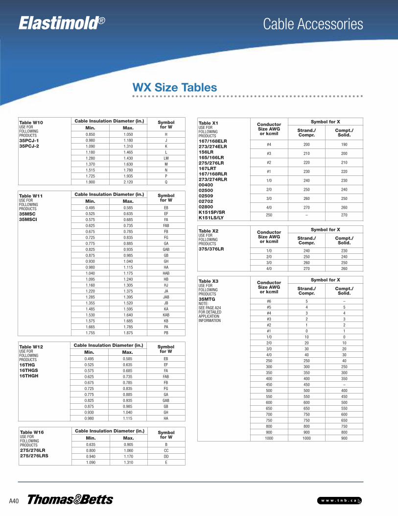
Elastimold® Cable Accessories
A40 w w w . t n b . c a
WX Size Tables
Table X1USE FORFOLLOWINGPRODUCTS167/168ELR273/274ELR156LR165/166LR275/276LR167LRT167/168RLR273/274RLR0040002500025090270202800K151SP/SRK151LS/LY
ConductorSize AWGor kcmil
Symbol for X
Strand./Compr.
Compt./Solid.
#4 200 190
#3 210 200
#2 220 210
#1 230 220
1/0 240 230
2/0 250 240
3/0 260 250
4/0 270 260
250 – 270
Table X2USE FORFOLLOWINGPRODUCTS375/376LR
ConductorSize AWGor kcmil
Symbol for X
Strand./Compr.
Compt./Solid.
1/0 240 2302/0 250 2403/0 260 2504/0 270 260
Table X3USE FORFOLLOWINGPRODUCTS35MTGNOTE:SEE PAGE A24FOR DETAILEDAPPLICATIONINFORMATION
ConductorSize AWGor kcmil
Symbol for X
Strand./Compr.
Compt./Solid.
#6 5 –#5 4 5#4 3 4#3 2 3#2 1 2#1 0 11/0 10 02/0 20 103/0 30 204/0 40 30250 250 40300 300 250350 350 300400 400 350450 450 –500 500 400550 550 450600 600 500650 650 550700 750 600750 750 650800 800 750900 900 8001000 1000 900
Table W12USE FORFOLLOWINGPRODUCTS16THG16THGS16THGH
Cable Insulation Diameter (in.) Symbolfor WMin. Max.
0.495 0.585 EB0.525 0.635 EF0.575 0.685 FA0.625 0.735 FAB0.675 0.785 FB0.725 0.835 FG0.775 0.885 GA0.825 0.935 GAB0.875 0.985 GB0.930 1.040 GH0.980 1.115 HA
Table W10USE FORFOLLOWINGPRODUCTS35PCJ-135PCJ-2
Cable Insulation Diameter (in.) Symbolfor WMin. Max.
0.850 1.050 H0.980 1.180 J1.090 1.310 K1.180 1.465 L1.280 1.430 LM1.370 1.630 M1.515 1.780 N1.725 1.935 P1.900 2.120 Q
Table W11USE FORFOLLOWINGPRODUCTS35MSC35MSCI
Cable Insulation Diameter (in.) Symbolfor WMin. Max.
0.495 0.585 EB0.525 0.635 EF0.575 0.685 FA0.625 0.735 FAB0.675 0.785 FB0.725 0.835 FG0.775 0.885 GA0.825 0.935 GAB0.875 0.985 GB0.930 1.040 GH0.980 1.115 HA1.040 1.175 HAB1.095 1.240 HB1.160 1.305 HJ1.220 1.375 JA1.285 1.395 JAB1.355 1.520 JB1.485 1.595 KA1.530 1.640 KAB1.575 1.685 KB1.665 1.785 PA1.755 1.875 PB
Table W16USE FORFOLLOWINGPRODUCTS275/276LR275/276LRS
Cable Insulation Diameter (in.) Symbolfor WMin. Max.
0.635 0.905 B0.800 1.060 CC0.940 1.170 DD1.090 1.310 E
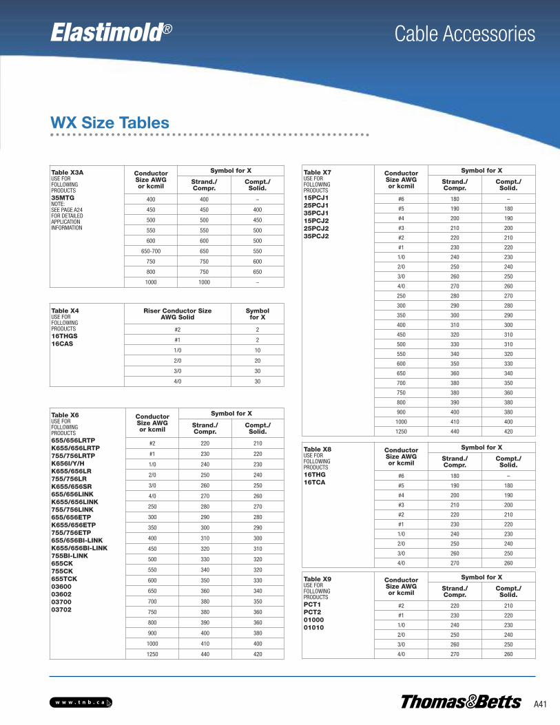
Elastimold® Cable Accessories
A41w w w . t n b . c a
WX Size Tables
Table X3AUSE FORFOLLOWINGPRODUCTS35MTGNOTE:SEE PAGE A24FOR DETAILEDAPPLICATIONINFORMATION
ConductorSize AWGor kcmil
Symbol for X
Strand./Compr.
Compt./Solid.
400 400 –
450 450 400
500 500 450
550 550 500
600 600 500
650-700 650 550
750 750 600
800 750 650
1000 1000 –
Table X4USE FORFOLLOWINGPRODUCTS16THGS16CAS
Riser Conductor SizeAWG Solid
Symbolfor X
#2 2
#1 2
1/0 10
2/0 20
3/0 30
4/0 30
Table X6USE FORFOLLOWINGPRODUCTS655/656LRTPK655/656LRTP755/756LRTPK656I/Y/HK655/656LR755/756LRK655/656SR655/656LINKK655/656LINK755/756LINK655/656ETPK655/656ETP755/756ETP655/656BI-LINKK655/656BI-LINK755BI-LINK655CK755CK655TCK03600036020370003702
ConductorSize AWGor kcmil
Symbol for X
Strand./Compr.
Compt./Solid.
#2 220 210
#1 230 220
1/0 240 230
2/0 250 240
3/0 260 250
4/0 270 260
250 280 270
300 290 280
350 300 290
400 310 300
450 320 310
500 330 320
550 340 320
600 350 330
650 360 340
700 380 350
750 380 360
800 390 360
900 400 380
1000 410 400
1250 440 420
Table X7USE FORFOLLOWINGPRODUCTS15PCJ125PCJ135PCJ115PCJ225PCJ235PCJ2
ConductorSize AWGor kcmil
Symbol for X
Strand./Compr.
Compt./Solid.
#6 180 –
#5 190 180
#4 200 190
#3 210 200
#2 220 210
#1 230 220
1/0 240 230
2/0 250 240
3/0 260 250
4/0 270 260
250 280 270
300 290 280
350 300 290
400 310 300
450 320 310
500 330 310
550 340 320
600 350 330
650 360 340
700 380 350
750 380 360
800 390 380
900 400 380
1000 410 400
1250 440 420
Table X8USE FORFOLLOWINGPRODUCTS16THG16TCA
ConductorSize AWGor kcmil
Symbol for X
Strand./Compr.
Compt./Solid.
#6 180 –
#5 190 180
#4 200 190
#3 210 200
#2 220 210
#1 230 220
1/0 240 230
2/0 250 240
3/0 260 250
4/0 270 260
Table X9USE FORFOLLOWINGPRODUCTSPCT1PCT20100001010
ConductorSize AWGor kcmil
Symbol for X
Strand./Compr.
Compt./Solid.
#2 220 210
#1 230 220
1/0 240 230
2/0 250 240
3/0 260 250
4/0 270 260

Elastimold® Cable Accessories
A42 w w w . t n b . c a
Shrink-Fit Cable Joints
The Faster, Easier Way to Splice Medium-Voltage Cables inDirect-Burial, Underground or Overhead Applications.Features
• Automatic core removal without ripcords or heat required for installation
• High-quality molded EPDM elastomer housing withstands the elements in harsh direct-burial, vault, manhole and overhead applications
• Four sizes support a wide range of cable and conductor sizes
• IEEE 404 rated shrink-fit cable joint
Typical Applications
• Direct Burial• Handhole/Pullbox• Manhole• Vault• Overhead
For over 50 years, the Elastimold® brand has been associated with reliable, high-quality, pre-molded power cable splices that are designed to stand the rigors of the toughest utility applications. These products provide a cost-effective method to splice medium voltage cablesusing a “push-on” motion, and allowing cable neutrals to be solidly connected across the bodyof the splice without the use of any external braids. For those who prefer a more range-takingsolution without the use of any physical force to install, the only options available have beencumbersome heat-shrink products that require multiple steps and the use of an open flame thatmay not result in uniform cable coverage, or over-designed cold-shrink products that either useawkward, entangling ripcords or expensive braid/jacket combinations that do not offer the abilityto solidly connect neutrals across the splice.
Now there’s a faster and easier way to splice medium-voltage cables — one that combines allof the convenience and flexibility of a pre-molded splice, with the range-taking ease of installation offered in a cold- or heat-shrink product, but without the use of ripcords, heat or excessive force. Introducing, the NEW Elastimold® Shrink-Fit Cable Joints from Thomas & Betts!
The Shrink-Fit Cable Joints are made of the same molded EPDM elastomer as our other Elastimold® cable accessories. This high-performance material offers more durability than silicone for direct burial. The joints feature a four-piece plastic support core, which is placed overthe cable for installation of the splice. The support core is then easily removed with the suppliedtool, allowing the elastomer joint to contour over the spliced cable for a uniform seal every time.
Each Elastimold® Shrink-Fit Cable Joint covers a wide range of cable sizes, features an insulated, semi-conductive shield and can be used with either a standard aluminum or optionalcopper compression splice. Optional kits are available for neutral, shielding and jacket restoration.
SFJ115Shrink-Fit Cable Joint
SFJ415Shrink-Fit Cable Joint
Disposable four-piece plastic support core

Elastimold® Cable Accessories
A43w w w . t n b . c a
Shrink-Fit Cable Joints
Installation Sequence
Place Elastimold® Shrink-FitJoint in position.
Install connector. Cut fastening straps. Automatic coredetachment begins.
Crimp grounding wires.Last core piece detaches.Core automatically detachesfrom second end.
Core pushes itself towards theends of the Shrink-Fit Joint.
Volt Class 15 kV 25/28 kV 35 kVMax. Phase-to-Ground Operating Voltage 8.7 kV 14.4 kV 20.2 kV
BIL Impulse Withstand (1.2 x 50μsec. wave) 110 kV 150 kV 200 kV
Corona Extinction Level @ 3.0 pC Sensitivity 13 kV 22 kV 30 kV
DC Withstand during Installation 56 kV 80 kV 100 kV
DC Withstand up to 5 yrs.* — XLPE Insulation 18 kV 25 kV 31 kV
DC Withstand up to 5 yrs.* — EPR Insulation 45 kV 64 kV 80 kV
AC Withstand at 60 Hz for 60 sec. 35 kV 52 kV 69 kV
Continuous Current Equal to that of cable
Short-Term Current Equal to that of cable up to 35 kA
*Reference: AEC CS6 and CS8, section L.2.
Ratings
CableJoint Size
D(in.)
L(in.)
1 1.85 11
2 2.12 16
3 2.4 18
4 2.6 18
Dimensions
CableJoint Size
Min.(in.)
Max.(in.)
Min.(mm)
Max.(mm)
1 0.620 0.780 15.75 19.81
2 0.815 0.920 20.70 23.37
3 0.935 1.190 23.75 30.23
4 1.210 1.760 30.73 44.70
Insulation Range
How to construct a catalogue number for an Elastimold® Shrink-Fit Cable Joint:
S F J
Voltage Rating
15 11 kV
25 25/28 kV
35 35 kV
Connector Type
C Crimp
Conductor
1 Aluminum
2 Copper
Cable Joint Size
SizeCode
Wall Thickness
(mils)
Min. Conductor
Size*
Max. Conductor
Size*15 kV
1
175
#2 AWG 3/0 AWG2 4/0 AWG 250 kcmil3 350 kcmil 600 kcmil4 700 kcmil 1000 kcmil1
220
#2 AWG 1/0 AWG2 2/0 AWG 4/0 AWG3 250 kcmil 500 kcmil4 600 kcmil 1000 kcmil
25/28 kV2
260#1 AWG 2/0 AWG
3 3/0 AWG 350 kcmil4 500 kcmil 1000 kcmil
35 kV3
3451/0 AWG 4/0 AWG
4 250 kcmil 1000 kcmil
Connector Size
XCode
Conductor Size (AWG or Kcmil)
Stranded/Compressed
Solid/Compact
210 – #2 AWG220 #2 AWG #1 AWG230 #1 AWG 1/0 AWG240 1/0 AWG 2/0 AWG250 2/0 AWG 3/0 AWG260 3/0 AWG 4/0 AWG270 4/0 AWG 250 kcmil280 250 kcmil 300 kcmil290 300 kcmil 350 kcmil300 350 kcmil 400 kcmil310 400 kcmil 500 kcmil330 500 kcmil 650 kcmil360 650 kcmil 750 kcmil380 750 kcmil 900 kcmil400 900 kcmil 1000 kcmil410 1000 kcmil –
* Based on the minimum compact AEIC and ICEA cable insulation diameters.Note: Each kit contains shrink-fit housing on removable core, splice connector, lubricant, installation instructions and crimp chart. For ordering information on optional neutral, shielding and jacket restoration kits, please contact your RegionalSales Office.

Elastimold® Cable Accessories
A44 w w w . t n b . c a
Ranger2™ Terminations
OverviewElastimold® Ranger2TM Terminations are specifically designed for use on 15 thru 35 kV, XLP orEPR insulated, underground power distribution cable systems. Units allow proper transition andconnection of the underground cable system to bare overhead conductors and live front equipment. Applications include indoor, outdoor, riser pole, padmounted and other live front orweather exposed installations. Designs use advanced silicone rubber insulating materials to provide necessary creep, strike, weather sealing and contamination resistance, assuring properperformance in the most severe conditions. The grey color blends in with outdoor environments.
Ranger2 Terminations support a wide application range with only three sizes required to cover#2 AWG through 1250 kcmil cables. The single-piece 15 kV and 25 kV shrink-fit design makesinstallation effortless, and the two-piece 35 kV design facilitates easier core removal. Simply position the terminator on the prepared cable and remove the center core. Units are compactand lightweight, allowing installation in restricted spaces and free-hanging applications.
Silicone Polymer Housings
The R2T and R2IT terminations are manufactured using an optimized weather-resistant silicone formulation. The housing offers superior cablesealing and voltage withstand characteristics. Elastimold terminations meet or exceed all requirements of IEEE Standard 48 for Class 1 outdooror Class 2 indoor terminations. Unit tests include voltage withstand wet and dry, before and after load cycling on units installed on maximumconductor sized cable.
Kit Contents
Every R2T and R2IT comes complete with housing and stress tubepreassembled on the core, ready for installation. Easy-to-read installation instructions will take you from cable preparation throughinstallation. All kits include a tube of silicone grease, two plasticgloves and one strip of self-fusing silicone tape. Outdoor kits alsoinclude mastic for sealing. Metallic Tape (M) kits include a groundingadapter for Tape Shield, Wire Shield and UniShield cables. LC Shield(L) kits include a high ampacity grounding adapter for LongitudinallyCorrugated Shield, Tape Shield and Wire over Tape Shield cables.
Stress Relief
The R2T and R2IT terminations provide electric stress control for the cable by means of a flexible tube with a high permittivity dielectricconstant. The stress-relief tube is preassembled on the core under the polymer housing. As the core is removed, the stress-relief tube and housing shrink onto the cable at the same time, in exactly the right position. No secondary operations are required during installation. The electrical fields are refracted through the high dielectric constant tube and housing as shown.
Installation
Standard cable preparation techniques are used for all R2T, Elastimold Ranger2 Outdoor Terminations, and R2IT, Elastimold Ranger2 Indoor Terminations. The Elastimold shrink-fit terminations are assembled on a removable core. After the termination is placed onto the preparedcable, the core is removed by pulling on the end. The housing then collapses onto the prepared cable. Memory of the material provides the interface solid dielectric and sealing properties required to meet the electrical ratings and prevent the ingress of moisture.
Stress ReliefVoltage Stress
Terminal Housing Terminal Stress Relief
Cable Insulation Conductor
Cable Semi-Conductor1
2
3
4
5
1
2
3
4
5

Elastimold® Cable Accessories
A45w w w . t n b . c a
Ranger2™ Terminations
Overview
Features Benefits/Descriptions
Silicone Polymer Housing Superior memory and weathering characteristics
Shrink-Fit Housing Uses common installation procedures and cable preparation dimensions. Field-removable center core allows for easy installation.
Three Different Shed Designs for Superior Weathering• Four sheds for 15 kV outdoor model• Six sheds for 25/28 kV outdoor model• Eight sheds for 35 kV outdoor model
Wide Range Three sizes cover entire cable range from #2 AWG to 1250 kcmil. Units accommodate popular XLP and EPR cable types and shield constructions.
Integral Hi-K Voltage Stress-Control Tube Provides uniform voltage grading over the length of the termination. Eliminates damaging voltage stress concentrations at the cable insulation shield edge. Thick wall construction securely maintains critical interface pressure for consistent long term reliability and performance.
Pull-Down Tabs for Easy Installation of Built-In Jacket Seal Accommodates CN, JCN, Tape, Wire or LC shielded cable construction
Lightweight, Compact Design Installs in restricted spaces. Permits application where free hanging is desired.
Dark Grey Molded Silicone InsulatorBlends well into outdoor environments. Utilizes specially formulated silicone materials with improved UV stability, track, erosion and weather resistance. Outdoor styles feature large diameter, multi-shed profile with extra creep and strike for enhanced performance under the worst environmental conditions.
Optional Connectors Connector with copper stem, one-hole and two-hole spade connector
Optional Cable and Support Bracket Three sizes, ranging from 0.80 in. – 1.95 in. O.D.
Typical Installation on Jacketed Concentric Neutral (JCN) Cable
IEEE 48 Standard for indoor and outdoor cable terminations
ANSI C119.4 Standard for cable connectors for aluminum and copper conductors
AEIC CS8-06 and ANSI/ICEA S-94-649-2004and S-97-682-2000 Standards for XLP and EPR insulated cables
Elastimold Ranger2 Terminations have been designed and tested per applicable portions of ANSI, IEEE, AEIC, ICEA and other industry standards.
Certified
Connector
Grey MoldedSilicone Insulator Built-In Cable
Entrance Seal Cable Jacket
Concentric Neutral Wires
MasticCableShield
Hi-K VoltageStress-Control Tube
CableInsulation
SiliconeTape Seal
Ratings Indoor Outdoor Outdoor OutdoorTermination Catalogue Series R2IT15 R2T15 R2T28 R2T35Sizes Available* 1, 2, 4 1, 2, 4 2, 4 2, 4Voltage Rating (kV) 15 15 25/28 35Max. Design Voltage to Ground (kV) 9.5 9.5 16 22Corona Extinction Voltage (kV) (≤3 p.c.) (Partial Discharge) 13 13 22 30
Insulation Withstand Voltage:
Lightning Impulse (BIL Dry 110 Withstand) (kV Crest) 110 110 150 20010 Sec. Wet (60 Hz) (kV) — 45 60 801 Minute Dry (60 Hz) (kV) 50 50 65 905 Hour Dry (60 Hz) (kV) 36 35 55 75DC Withstand 15 Min. Dry (kV) 75 75 105 140
Ratings
Dimensions Indoor Outdoor Outdoor OutdoorTermination Catalogue Series R2IT15 R2T15 R2T28 R2T35Sizes Available* 1, 2, 4 1, 2, 4 2, 4 2, 4Voltage Rating (kV) 15 15 25/28 35Number of Sheds 0 4 6 8Minimum Strike Distance in. (mm)
8.4 (213)11.6 (295) 14.5 (368) 16.8 (427)
Creepage Distance in. (mm) 15.0 (381) 22.8 (579) 30.0 (762)
Dimensions
IEEE 48 Classification Outdoor = Class 1A, Indoor = Class 2Ambient Temperature Range -30ºC to 65ºCPower System Frequency 48 to 62 HzAltitude Range 3 300 ft. max.Mounting Free hanging or optional bracket
Application Information
* See page A46 for cable insulation diameter ranges. * See page A46 for cable insulation diameter ranges.

Elastimold® Cable Accessories
A46 w w w . t n b . c a
Ranger2TM Terminations Base Catalogue Numbers
The R2T and R2IT termination design couples shrink-fit technology and Elastimold’s pull-down jacket seal feature to provide a termination linethat covers the widest range of applications with the fewest number of models. Three sizes cover 0.64 in. (16 mm) to 2.10 in. (53 mm) insulation diameter cables (#2 AWG through 1250 kcmil).
The R2T housings are designed for maximum performance in all field conditions with superior creepage and strike distances for long-term service. Insulating silicone sleeves are also available when more creepage is required or when wildlife protection is needed to insulate theconnectors. Contact your Thomas & Betts Sales Representative for further information.
kVClass Type
Cable Range(InsulationDiameter)
Cat. No.
(in.) mmConcentric Neutral and Jacketed Concentric
Neutral Cable
Tape Shield, Wire Shield and UniShield Cable
LC Shield, Wire over TapeShield and Tape Shield Cable
15 Indoor
0.64 to1.12
16.3 to 28.4 R2IT15J1 R2IT15M1 R2IT15L1
0.84 to1.38
21.3 to 35.1 R2IT15J2 R2IT15M2 R2IT15L2
1.30 to2.10
33.0 to 53.3 R2IT15J4 R2IT15M4 R2IT15L4
15 Outdoor
0.64 to1.12
16.3 to 28.4 R2T15J1 R2T15M1 R2T15L1
0.84 to1.38
21.3 to 35.1 R2T15J2 R2T15M2 R2T15L2
1.30 to2.10
33.0 to 53.3 R2T15J4 R2T15M4 R2T15L4
25/28 Outdoor
0.84 to1.38
20.3 to 35.1 R2T28J2 R2T28M2 R2T28L2
1.30 to2.10
33.0 to 53.3 R2T28J4 R2T28M4 R2T28L4
35 Outdoor
0.84 to1.38
20.3 to 35.1 R2T35J2 R2T35M2 R2T35L2
1.30 to2.10
33.0 to 53.3 R2T35J4 R2T35M4 R2T35L4

Elastimold® Cable Accessories
A47w w w . t n b . c a
Ranger2TM Terminations Accessories Connector Options
Type Material Conductor Conductor Size Connector Prefix*
Stem CompressionConnector Aluminum
Aluminum or Copper
#2 through 4/0(34–107 mm2)
T0
Aluminum Only T1
One-HoleSpade Connector Tinned Aluminum Aluminum or Copper #2 through 500 kcmil
(34–253 mm2) H0
Two-HoleSpade Connector Tinned Aluminum Aluminum or Copper #2 through 1250 kcmil
(34–633 mm2) N0
* See page A48 for conductor code.
Cable Support Bracket OptionsRanger2 Terminations are compact, lightweight and frequently allow use of free-hanging mounting methods. Optional cable support brackets are available if required.
Optional Cable Support Brackets
Type Cable Range (in.)(Overall O.D.) Cat. No. Suffix No.
Single Clamp 0.80–1.25 (20–32 mm) JB-1 B1
Single Clamp 1.10–1.50 (28–38 mm) JB-2 B2
Double Clamp 1.45–1.95 (37–50 mm) JB-3 B3

Elastimold® Cable Accessories
A48 w w w . t n b . c a
How to construct a catalogue number for Ranger2 Terminations:
Housing Only
Type
Outdoor R2T
Indoor R2IT
ConductorCode
Stranded orCompressed
Compact orSolid
210 – #2220 #2 #1230 #1 1/0240 1/0 2/0250 2/0 3/0260 3/0 4/0270 4/0 250280 250 300290 300 350300 350 400310 400 500330 500 600360 650 750380 750 900400 900 1000410 1000 –440 1250 –
Ranger2TM Terminations Ordering Information
–
Add a connector – Add a cable support bracket
XXX XX X X XX XXX
–
– XX
kV Code
15 kV 15
25/28 kV 28
35 kV 35
Cable Type
J Concentric Neutral/JacketedConcentric Neutral
M Tape Shield/Wire Shield/UniShield
L LC Shield Tape Shield/WireOver Tape Shield
Insulation Range
1 0.64 in.–1.12 in. (16 mm–28 mm) (15 kV only)
2 0.84 in.–1.38 (21 mm–35 mm)(15 kV, 25 kV, 35 kV)
4 1.30 in.–2.10 in. (33 mm–53 mm)15 kV, 25 kV, 35 kV)
Connector Type
T0 Universal Aluminum Barrel for AL or CUconductor w/Copper Wire Lead #2–4/0
T1 Aluminum Barrel for AL conductor onlyw/Copper Wire Lead #2–4/0
H0 Aluminum 1-Hole Spade #2–750 kcmil
N0 Aluminum 2-Hole Spade #2–1250 kcmil
Cable Mounting Bracket
B1 0.80–1.25 (20–32)
B2 1.10–1.50 (28–38)
B2 1.45–1.95 (37–50)
Connector only
Step 1. Selectthe TerminationHousing:A. Select Outdoor or
Indoor housing styleB. Select applicable
voltage classC. Select neutral/
shield typeD.Select the size
based on the cableinsulation diameter*
Step 2. Select theConnector:E. Select desired
connectorF. Select connector code
based on conductor size and conductor type
Step 3. Select theCable SupportBracket:G. Select cable support
bracket based on theoverall O.D. of the cable
Connector Option
Cable SupportBracket Option
* To help in selecting the proper terminator, ICEA and AEIC standard dimensions for XLP and EPR cables are shown in pages A35 to A37.

Elastimold® Cable Accessories
A49w w w . t n b . c a
Ranger2TM Terminations Installation
Typical Installation of Elastimold Shrink-Fit Terminations (R2T — Outdoor and R2IT — Indoor)
5. Apply a liberal bead of silicone lubricant to the semi-conshield step.
6. Pull the loose end of the core cord untilthe core is even with the end of the termination housing.
7. Position the terminator onto the cable.
8. Shrink into place by unwinding the removable core.
9. Apply silicone lubricant to skirt and mastic area.
10.Fold down the skirt over the mastic to seal the cable entrance.
11.Seal the top of the terminator at the connector area with silicone tape.
12.Attach the neutral wires or optional ground braid to the system ground per local code. Install the optional cable support bracket if required.
1. Train the cable into position and cut to length. Using standard practices, cut back the cable jacket, metallic shield, semi-conductive shield and cable insulation, exposing the conductor.
2. Finish preparing the metallic shield. For concentric neutral or jacketed concentric neutral cables, bend back the neutral wires and seal with mastic strips and vinyl tape.
For metallic tape, drain wire, UniShield or LC Shield cables: install the ground braid using the constant force spring and seal with mastic strips and vinyl tape.
3. Clean the exposed conductor, install and crimp the connector.
4. Use mastic and vinyl tape to fill any gap or step between the connector and the cableinsulation. Clean the cable.
1 2 3 4 5 6
8
7
9
10 11 12

Fisher Pierce® Cable Accessories
A50 w w w . t n b . c a
Faulted Circuit Indicators
Series 1548 Overhead FCIs
FCIs with Radio Transmitters
Series 1548 radio FCIs can signal faults to handheld receivers, radio receivers and theSmartLink™ Series 5000 cellular remote terminal unit (RTU) systems integrated with SCADA and web-based reporting systems. Status, alarms and other event notifications can beintegrated into SCADA systems, as well as sent to customer-designated personnel via e-mail,pager or text message. Having precise fault information reduces outage duration, improvessystem reliability and lowers operation costs.
Reliable fault indication for single-phase overhead applications
Trip/Reset Tool AT2186-10Manual trip/reset test for both permanent and temporary fault indication using hotstick-mountablereset tool.
Swipe Here
Trip Logic Adaptive or fixed current trip with inrush restraint logic. Adaptive triplogic eliminates the need for trip-rating selection or revision with changing load.
Reset Logic Automatic reset with return of load current and/or time reset ofpermanent fault indication. Automatic time reset for temporary fault indication.Manual trip test and reset capabilities using hotstick-mountable trip/reset tool.
Fault Indication Visual indication choices of LED, 5-LED Array, Flag or StrobeLight. Highly viewable 360º indication (Strobe or LED). Radio fault reporting capability also available.
Mounting Hotstick mounting with automatic torque limiting.
Replaceable Lithium Battery Offers 10-year, maintenance-free service life.(Note that Flag model has non-replaceable battery).
Supports a Wide Range of Conductors Mounts on conductors with diametersfrom 0.14 in. to 1.20 in. (3.56 mm to 30.48 mm).
Optional Features Available Options include temporary/permanent fault indication, instantaneous recloser coordination feature and backfeed restraintusing a delay-trip scheme (requires protective device to pass two cycles minimum of fault current before closing).
Technical Specifications
Fault Registration: Red, high-intensity LED with choice of hard-wired or fiber optic cableremote mounting or audible intermittent beeper signalTrip current: Factory preset to customer specifications within range of 50 A and 100 A to 1,500 A in 100 A incrementsTrip Current Accuracy: ±10% of trip rating (calibrated using 1 in. dia. cable for 400 Atrip or less or 2.0 in. dia. cable for greater than 400 A trip)Trip Response Speed: Consult trip curves (coordinated to properly applied link, expulsion, power and current-limiting fuses)Reset Time: 4 hrs., 2 hrs., 1 hr., manual trip/reset standardOverload Capacity: Capable of withstanding 25,000 A for 10 cyclesContinuous Load Current: Rated at 1,000 A max.Temperature Range: -40°C to 85°CSubmersibility: Tested to 30 ft.Operating Battery Life: 800 hrs. for LED indication, 160 hrs. for audible indication, both with 10-yr. life at 20°C Battery: Long-life lithium cellCable Ranges: 0.63 in. (16 mm) to 1.58 in. (40 mm); 1.58 in. (40 mm) to 2.36 in. (60 mm); 2.36 in. (60 mm) to 3.55 in. (90 mm)Remote Fiber Optic Options: Permanent or removable (10 ft. standard, 30 ft. max.)Certifications: Complies with ANSI/IEEEE 495-1986

Fisher Pierce® Cable Accessories
A51w w w . t n b . c a
Faulted Circuit Indicators
Underground/Padmount Faulted Circuit IndicatorsSeries 1541/42/43 Automatic Time Reset FCIsThe following diagram shows how to construct a catalogue number for Series 1541/1542/1543 FCIs. Not all combinations are possible; consult your Regional Sales Office for ordering assistance.
Indicates field that must be filled in to complete order.
NOTE: Availability of selected configuration will be verified at quotation time.
5 4
Basic Model
1541 Single-Phase
1542 Two-Phase
1543 Three-Phase
Indication/Battery Options
H LED, non-replaceable battery, hotstick mounted
R LED, replaceable battery, hotstick mounted
A Audible alarm indication, replaceable battery, hotstick mounted
Inrush Restraint
F Inrush time overcurrent(dual curve) standard
N Non-inrush delay
1 B
Trip Point
0.5 50 A
0.6 60 A
1 100 A
2 200 A
3 300 A
4 400 A
4.5 450 A
5 500 A
6 600 A
8 800 A
10 1000 A
12 1200 A
15 1500 A
Cable Clamp Size
S Small 0.63 in.–1.58 in. cable dia.
M Medium 1.58 in.–2.36 in. cable dia.
L Large 2.36 in.–3.55 in. cable dia.
Display Options
R Remote LED
TIntegral LED or audible alarm (always selected with code “A” or “H” under
Indication/Battery Options)
E Remote LED, fiber optic cable
F Remote LED, removable fiber optic cable
Length of Remote LED Cable
N Not applicable when code “T” is selected under Display Options
10 Remote LED, removable fiber optic cable
Reset Time Delay After Fault Occurrence
A 4-hr. automatic reset time delay
B 2-hr. automatic reset time delay
C 1-hr. automatic reset time delay

Cable Accessories
A52 w w w . t n b . c a
Faulted Circuit Indicators
Test Point Fault Indicators TPM SeriesMount directly to any IEEE 386 standard capacitive test point.Test Point Mounted Fault Indicators consist of a solid-state current sensor connected to a faulted-circuit display, providing a clear visual means for quickly locating faulted cables andequipment on underground distribution systems. Designs incorporate advanced circuit logic andmonitoring system protection operation to prevent the indicator from tripping unless an overcurrent condition is followed by a loss of system voltage. Trip and reset operations are automatic, and for versatility and convenience, the same indicator may be used for 5 kV thru 35 kV applications.
AccQTrip™ Logic Circuitry Prevents false indications in voltage-reset units due to inrush currents, cold load pickup and overloading.
High/Low Trip-Setting Selection Requires no minimum load current and no load surveys.
Internal Magnetic Shielding Prevents adjacent phase effects.
1 msec. Trip Response Coordinates with current-limiting fuses, as well as other protection devices.
Magnetically Latched Flag Prevents flag indication from changing state due to shock or vibration.
Test Point Mounting Mounts directly to 200 and 600 A elbows, splices and other cable accessoriesequipped with IEEE 386 standard capacitive test points.
Built-In Pulling Eye Enables safe, easy hotstick installation and removal from test points.
Durable Construction Enclosed in a rugged, yet lightweight and compact, sealed, impact- and corrosion resistant Lexan housing with EPDM molded-rubber test point mounting boot.
Basic Operation
A faulted circuit produces an associated magnetic field, which closes a reed switch in the indicator, resulting in a tripped display. Trip responseoccurs in .001 seconds (1 msec.), allowing the fault indicator to properly coordinate with all types of circuit-protection schemes, including current limiting fuses. To eliminate confusing false trips, voltage-reset indicators are equipped with inrush, backfeed, overload and cold-loadpick-up restraint circuitry. Current sensors feature internal shielding to prevent inadvertent tripping when located in close proximity to adjacentphases, such as in junction-mounted applications.
Fisher Pierce®
Trip Point VS. Cable DiameterTime/current Curve for TPMVF, VL, VOL,TL

Cable Accessories
A53w w w . t n b . c a
Faulted Circuit Indicators
Test Point Fault Indicators TPM Series
Cat. No. Description
TPMTL-[ _ ] Time Reset with LED Display (auto-resets to normal after 4 hrs.; may also be manually reset using an FTT test tool)
TPMVF-[ _ ] Voltage Reset with Flag Display (auto-resets to normal after system voltage restoration; reset requires 5 kV min. voltage with time required for reset proportional to system voltage)
TPMVL-[ _ ] Voltage Reset with LED Display (auto-resets to normal after system voltage restoration; reset requires 5 kV min. voltage with time required for reset proportional to system voltage)
TPMVOL-[ _ ] Voltage Operated, Time Reset, LED Display (auto-resets after 4 hrs.; longer time resets available upon request)
Cat. No. Suffix Description
-LT For 200 A. All fused taps use LOW trip rating. For URD applications, use LOW trip rating.
-HT For 600 A. For URD applications, use HIGH trip rating.
NOTE: For overhead bulk feeder applications, use HIGH or LOW trip ratings (whichever is greater than the minimum pickup setting of the related protection device).AccQTrip™ and AccQClamp™ are trademarks of Quality Indications, Inc.
(all dimensions (in.) with millimeter equivalents in parentheses)
Test Point
Pulling Eyefor HotstickInstallationand Removal
Faulted Circuit Display
Test Point Mounting Plug
3-7/8(98)
1-1/8(29)
1-3/8(35)
2-1/4(57)
3-1/4(83)
Fisher Pierce®

Cable Accessories
A54 w w w . t n b . c a
Fisher Pierce®
Faulted Circuit Indicators
Overhead Line Fault Indicators OLM SeriesLocate faulted circuits and equipment on overhead distribution systems
Self-powered Fisher Pierce® Series OLM Overhead Line Fault Indicators consist of a solid-statecurrent sensor connected to a faulted circuit display. Advanced circuit logic monitors system protection operation and prevents indicator tripping unless an overcurrent condition is followed bya loss of system voltage. Trip and reset operations are automatic, and the same indicator may beused for 5 kV thru 35 kV line-to-ground applications. These compact, sealed and corrosion-resistant units are designed for direct installation to an overhead line using a spring-loaded, over-center toggle clamp. Equipped with retainer pads to prevent slip and twist, theclamp positions the conductor at a constant distance from the current sensor, maintaining trip accuracy over the entire conductor diameter range of .4 in. to 2.2 in.
Basic Operation
A faulted circuit produces a magnetic field, which closes a reed switch in the indicator and causesa tripped display. A trip response time of .001 seconds enables the indicator to properly coordinatewith all circuit-protection schemes, including current-limiting fuses. To eliminate confusing falsetrips, indicators feature inrush, overload and cold-load pickup restraint circuitry as standard. Internal shielding of current sensors prevents inadvertent tripping when in close proximity to adjacent phases.
AccQTrip™ Logic Circuitry In voltage reset units preventsfalse indications due to inrush currents, cold load pickupand overloading.
AccQClamp™ Mounting Provision Universal one-size-fits-all design automatically adjusts.
High/Low Trip Setting Selection No minimum load currentrequirement and no load surveys needed.
Trip Response of .001 Seconds Coordinates with current-limiting fuses, as well as other protection devices.
Internal Magnetic Shielding Prevents adjacent phase effects.
Magnetically Latched Flag Indication Flag indication willnot change states due to shock or vibration.
Lightweight Enclosure Compact and sealed.
Trip Point VS. Cable DiameterTime/current Curve for OLMVF, VL, VOL,TL
3-7/8(98)
1-1/8(29)1-1/8(29)
4-1/4(108)
4-1/4(108)Open2-1/4(57)
5-5/8(143)open
2-3/8(60)Open

Cable Accessories
A55w w w . t n b . c a
Faulted Circuit Indicators
Fisher Pierce®
Overhead Line Fault Indicators OLM Series
Cat. No. Description Reset Operation
OLMTL Time Reset with LED Display Indicator auto-resets to normal after a four hour time duration. indicator may also be manually reset using an FTT test tool.
OLMVF Voltage Reset with Flag Display Indicator auto-resets to normal after system voltage restoration. Reset requires 5 kV minimum voltage to operate. Reset operation time is proportional to system voltage.
OLMVL Voltage Reset with LED Display Example: at 15 kV, reset occurs 30 seconds after system voltage restoration.
OLMVOL Voltage Operated, Time Reset, LED Display Indicator auto-resets after a four hour time duration. Longer time resets are available upon request.
Cat. No. Suffix Description
LT All fused taps use LOW trip rating. For 600 A Overhead applications, use LOW trip rating.
HT For 600 A Overhead applications, use HIGH trip rating.
Accessories for Series TPM, VCM and OLM Fault IndicatorsFO-Cable06Remote Fiber Optic Indicator for Underground Fault Indicators with LED Display can be extended to the outside of enclosures and/or vaults for ease of access and fault location. All the hardware for mounting the remoteend of the cable to the enclosure is included. The display has a large reflective bolt to enhance visibility.
FTT (Field Test Tool)Permits field testing and reset of fault indicators and provides assurance that theindicator is properly functioning. The test tool is lightweight, portable and incorporates a built-in magnet which operates the indicator trip and resetfunctions. The unit is equipped with provisions for hotstick handlingand operation.
Cat. No. Description
FTT Field Test Tool, overall dimensions 2 in. wide x 3 in. high x 5⁄8 in. deep
FO-CABLE06 Remote Fiber Optic Indicator for UFI

Cable Accessories
A56 w w w . t n b . c a
Faulted Circuit Indicators
Fisher Pierce®
Voltage Flash Rate
5 kv 20
10 kv 40
15 kv 70
20 kv 100
Voltage Flash Rate
25 kV 140
30 kV 160
35 kV 180
2 (51)
1-3/4(44)
3-1/4(44)
3/8(10)
The V2 Voltage Indicator consists of a self-powered voltage sensor connected to a neon light thatflashes when energized. Simply plug it into any IEEE 836 standard capacitive test point to determine the energized status of underground distribution circuits. Because the flash rate is proportional to the phase-to-phase system voltage, as indicated in the chart, one V2 model supports a wide range of applications – from 5 to 35 kV.
Test Point V2 Voltage IndicatorEasy way to visually determine the energized status of underground distribution circuits
Test Point
Pulling Eye for Hotstick Installation and RemovalEPDM Molded
Rubber Housing
(all dimensions in inches with millimeter equivalents in parentheses)
Flashing NeonLight IndicatesEnergized Status
Test PointMounting Plug

Cable Accessories
A57w w w . t n b . c a
Elastimold®
Wide Application Range Single model supports applications from 5 kV to 35 kV.
Easy to Read Flash rate per minute indicates systemvoltage (see chart).
IEEE 386 Test Interface Mounts to 200 and 600 A elbows, splices and other cable accessory components equipped with IEEE 386 capacitive test points.
Rugged Construction Molded EPDM-rubber housing forshielded, sealed and corrosion-resistant construction.
Built-In Pulling Eye Enables safe, easy hotstick installation and removal from test point.
20-Year Neon Bulb Yields long, maintenance-free service life.
Testable with V2-TB Easily tested for confirmation ofproper operation with the V2-TB voltage indicator testbox.
Cat. No. Description
V2 Voltage Indicator with Neon Display
V2-TB Voltage Indicator Test Box
V2-TB Test Box for easy field testing of V2 Voltage IndicatorsIf the V2 Neon Voltage Indicator indicates a power failure in an underground distribution circuit, you’ll want to ensure that it’s actually the circuit that’s failed and not the V2 itself. For fast, simple assurance, field test the V2 with the compact, portable V2-TB Voltage Indicator Test Box, powered by replaceable C batteries.
Faulted Circuit Indicators
Test Point V2 Voltage Indicator (cont’d)
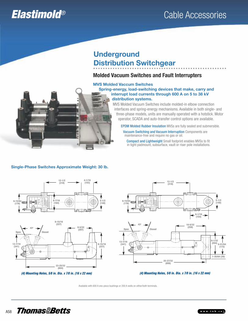
Elastimold® Cable Accessories
A58 w w w . t n b . c a
MVS Molded Vaccum SwitchesSpring-energy, load-switching devices that make, carry and
interrupt load currents through 600 A on 5 to 38 kV distribution systems.MVS Molded Vacuum Switches include molded-in elbow connection interfaces and spring-energy mechanisms. Available in both single- andthree-phase models, units are manually operated with a hotstick. Motoroperator, SCADA and auto-transfer control options are available.
EPDM Molded Rubber Insulation MVSs are fully sealed and submersible.
Vacuum Switching and Vacuum Interruption Components are maintenance-free and require no gas or oil.
Compact and Lightweight Small footprint enables MVSs to fit in tight padmount, subsurface, vault or riser pole installations.
Single-Phase Switches Approximate Weight: 30 lb.
12-1/2(318)
4-1/16(103)
5-1/2(140)
6-7/16(164)
6-15/64(176)
6-15/64(176)
12-1/2(318)
5-1/2(140)
6-1/16(154)
13-7/16(341)
43o
Open Closed
10-5/32(258)
8-1/32(204) 6-51/64
(173)
1-35/64 (39)
25-27/32(656)
23-25/32(604)
8-5/32(207)
8-15/16(227)
8-15/16(227)
43o
Open Closed
13-7/16(341)
(4) Mounting Holes, 5⁄8 in. Dia. x 7⁄8 in. (16 x 22 mm) (4) Mounting Holes, 5⁄8 in. Dia. x 7⁄8 in. (16 x 22 mm)
Available with 600 A one-piece bushings or 200 A wells on either/both terminals.
Molded Vacuum Switches and Fault Interrupters
UndergroundDistribution Switchgear

Elastimold® Cable Accessories
w w w . t n b . c a
UndergroundDistribution Switchgear
Maximum Design Voltage (kV) 15.5 27 38
Frequency (Hz) 50/60 50/60 50/60
BIL Impulse (kV) 95 125 150
One-Minute AC Withstand (kV) 35 60 70
Fifteen-Minute DC Withstand (kV) 53 78 103
Load Interrupting & Loop Switching (Amp) 600 600 600
Transformer Magnetizing Interrupting (Amp) 21 21 21
Capacitor or Cable Charging Interrupting (Amp) 40 40 40
Asymmetrical Momentary and 3-Operation Fault Close (Amp) 20 20 20
Symmetrical One-Second Rating (Amp) 12,5 12,5 12,5
Continuous Current (Amp) 600 600 600
Eight-Hour Overload Current (Amp) 900 900 900
Ratings Application Information• Construction: Submersible, corrosion resistant, fully shielded• Ambient Temperature Range: -40°C to 65°C
Certified TestsMVS loadbreak switches have been designed and tested per applicable portions of IEEE, ANSI, NEMA and other industry standards, including:IEEE C37.74 Standard for Subsurface, Vault and Padmounted Load-Interrupting SwitchesIEEE 386 Standard for Separable Connectors and Bushing InterfacesIEC 265 International Standards for Load-Interrupting SwitchesANSI C57.12.28 Standard for Padmount Enclosures
ClosedPosition
OperatingHandle
Patented Silicone Rubber DiaphragmSeparates Line and Ground Potential
Cable Connection Bushings
Spring Operating Mechanism Containedwithin 304 Stainless Steel Housing
Insulated DriveRod Assembly
Molded EPDM RubberInsulation and Shielding
Molded Vacuum Switches and Fault InterruptersThree-Phase SwitchesApproximate Weight: 135 lb.
18-1⁄2 in.(483 mm)
26 in.(660 mm)
14 in.(356 mm)
21 in.(533 mm)
18 in.(470 mm)
19 in.(483 mm)
9-1⁄2 in.(241 mm)
5-1⁄2 in.(140 mm)
Available with 600 A one-piece bushings or 200 A wells on either/both terminals.
5-1⁄2 in.(140 mm)
Vacuum InterrupterContact System
43oOpenPosition
A59

Elastimold® Cable Accessories
A60 w w w . t n b . c a
MVI Molded Vacuum Fault Interrupters
UndergroundDistribution Switchgear
Make, carry and automatically interrupt currents through 25,000 Asymmetrical on 5 to 38 kV distribution systemsMVI Molded Vacuum Fault Interrupters include molded-in elbow connection interfacesand tripfree mechanisms. They are available in single- and three-phase models. Unitsare self-powered and include current-sensing and electronic control.
UndergroundDistribution Switchgear
Combines Vacuum Interrupters, Programmable, Electronic, Self-Powered Controls and EPDM Rubber InsulationComponents provide compact, lightweight and submersible overcurrent protection.Field Programmable with a Wide Range of Time-Current Characteristic (TCC) Curves and Trip Settings TCC curves provide predictable tripping for ease of coordination with upstream and/or downstream protective devices.Control Monitors the Circuit ConditionWhen the programmed parameters are exceeded, a signal is sent to the tripping mechanism.Motor Operators and Controls AvailableEnable radial feeders or loops to be reconfigured, either manually or via SCADA.
200 A Wells
600 A Bushings
Front View Single-Phase
600 A T Elbow Interface
Conforms to ANSI Std. 386
6-1⁄4 in. (156 mm)
GroundLug
Programmable Control & Current Transformer
Open/ ResetClosed/Tripped
600 A BushingInterfaces
9-1⁄2 in.(241 mm)
2-57⁄64 in. (73 mm)
Well Interface AcceptsStandard Bushing Inserts
5-1⁄2 in. (140 mm)
30-5⁄8 in. (778 mm)
29-1⁄8 in.(740 mm)
12-1⁄2 in. (318 mm)
8-61⁄64 in. (227 mm)
5-27⁄32 in.(148 mm)
8-61⁄64 in.(227 mm)
8-15⁄16 in.(227 mm)
Front View Three-Phase
19 in..(483 mm)Mounting
32-7⁄8 in.(156 mm)
18-1⁄2 in. (470 mm)Mounting
14-3⁄32 in.(358 mm)Mounting
17-45⁄64 in. (277 mm)
10-57⁄64 in.(277 mm)
5-1⁄2 in. (140 mm)
LockingFeatures
Alternate Handle Position;Handle may be Repositioned in 60° Increments
5-1⁄2 in.(140 mm)
600 SeriesElbow Interfaces

Elastimold® Cable Accessories
A61w w w . t n b . c a
Voltage Class (kV) 15.5 15.5 15.5 27 35 35
Maximum Design Voltage (kV) 17 17 15.5 29 38 38
Frequency (Hz) 50/60 50/60 50/60 50/60 50/60 50/60
BIL Impulse Withstand (kV) 95 95 95 125 150 150
One-Minute AC Withstand (kV) 35 35 35 60 70 70
Five-Minute DC Withstand (kV) 53 53 53 78 103 103
Continuous Current (A) 600 600 600 600 600 600
Load Interrupting and Loop Switching (A) 600 600 600 600 600 600
Transformer Magnetizing Interrupting (A) 21 21 21 21 21 21
Capacitor or Cable Charging Interrupting (A) 40 40 40 40 40 40
Symmetrical/Asymmetrical Interrupting Capability (kA) 12.5/20 16/25.6 20/32 12.5/20 12.5/20 25/40
Current Sensor Ratio 1,000:1 1,000:1 1,000:1 1,000:1 1,000:1 1,000:1
Ratings
Application Information• Meets ANSI C37.60 requirements• Ambient Temperature Range: -40°C to 65°C
Certified TestsMVI Molded Vacuum Fault Interrupters have been designed and tested per applicableportions of IEEE, ANSI, NEMA and other industry standards, including:ANSI C37.60 Standard for Fault InterruptersIEEE 386 Standard for Separable Connectors and Bushing InterfacesANSI C57.12.28 Standard for Padmounted Enclosures
PositiveContactPosition
Operating Handle
Control Module (1-Phase)Sensing Module (3-Phase)
Patented Silicone Rubber DiaphragmSeparates Line and Ground Potential
Cable Connection Bushings
Spring OperatingMechanismwith Tripping
Insulated DriveRod Assembly
Molded EPDM RubberInsulation and Shielding Vacuum Fault Interrupter
Contact System
UndergroundDistribution Switchgear
MVI Molded Vacuum Fault Interrupters

Elastimold® Cable Accessories
A62 w w w . t n b . c a
Internal Control
This control is integral to the unit (no separate control box). It is accessible via a compu-ter connection to view or modify settings. This control is used on ganged three-phase orsingle-phase MVI interrupters. Phase and ground trip, as well as inrush restraint, areavailable. The E-Set software enables the user to connect to the internal control, eitherin the shop or in the field, to program or change settings. An MVI-STP-USB program-ming connector is required to connect between the PC and the MVI. With a computerconnected to the MVI control, the user can view real-time currents, the number of over-current protection operations, current magnitude of the last trip and the phase/groundfault targets. This is the standard control option.
External Control with Single-/Three-Phase Trip Selection (Style 10 and 310)
This control is mounted externally to the mechanism and provides the ability to selectTCCs by setting DIP switches on the front panel. Each phase can be assigned a differentminimum trip setting by means of manual rotary switches. This control is used on one,two or three single-phase MVI mechanisms.
External Control with Phase and Ground Trip (Style 20 and 320)
This control is mounted externally to the mechanism and provides the ability to selectphase minimum trip (one for all three phases), time delay for phase tripping, ground tripas a percent of phase minimum trip and ground trip delay by means of manual rotaryswitches. This control may be used on ganged three-phase or three single-phase MVImechanisms.
NOTE: E-Set can be downloaded from www.elastimoldswitchgear.com
Choose from five electronic control options to interrupt faults
Molded Vacuum Interrupters are provided with self-powered electronic control packages requiring no batteries or external power. Depending onthe application, five electronic control options are available for the MVI — see below and on following page.
Molded Vacuum Switches and Fault Interrupters
UndergroundDistribution Switchgear
Include Self-Powered Electronic Control Packages No batteries or external power are required. Controls send a signal to the vacuum interrupters to trip openand interrupt the fault when an overcurrent condition is detected.Field-Selectable Fuse or Relay Curves and Trip Settings One device for many protection schemes.

Elastimold® Cable Accessories
A63w w w . t n b . c a
UndergroundDistribution Switchgear
Molded Vacuum Switches and Fault Interrupters
External Control with Three-Phase Trip Only (Style 30 and 330)
This control is mounted externally to the mechanism and provides the ability to selectphase minimum trip (one for all three phases) by means of a manual rotary switch. Italso has an RS-232 port for connection to a PC to view the last trip data. This control isused on ganged three-phase or three single-phase MVI mechanisms.
External Control with Selectable Single-/Three-PhaseTrip Function (80 and 380 Control)This control is mounted externally to the mechanism of the interrupter and provides theability to select between a single-phase trip and a three-phase trip. The 80 and 380Control can be used with one three-phase interrupter or with three single-phase inter-rupters. For three-phase applications, the ground trip function can be blocked from thefront panel. Manual trip and reset target buttons are also located on the front panel. Thiscontrol uses the E-Set software, which enables programming via a computer using theMVI-STP-USB adapter. E-Set features custom TCC curves and provides access to thelast fault event information, as well as real-time current per phase.
Curve Reference No. Curve No. Curve Type
Relay Curves (minimum trip 30–600A)
MVI-TCC-01 1 E Slow
MVI-TCC-02 2 E Standard
MVI-TCC-03 3 Oil Fuse Cutout
MVI-TCC-04 4 K
MVI-TCC-05 5 Kearney QA
MVI-TCC-06 6 Cooper EF
MVI-TCC-07 7 Cooper NX-C
MVI-TCC-08 8 CO-11-1
MVI-TCC-09 9 CO-11-2
MVI-TCC-10 10 T
MVI-TCC-11 11 CO-9-1
MVI-TCC-12 12 CO-9-2
MVI-TCC-13 13 Cooper 280ARX
MVI-TCC-14 14 F
MVI-TCC-16 16 Kearney KS
MVI-TCC-17 17 GE Relay
MVI-TCC-18–23 18–23 CO-8-1–CO-8-6
MVI-TCC-24–27 24–27 CO-9-3–CO-9-6
MVI-TCC-28–31 28–31 CO-11-3–CO-11-6
Curve Reference No. Curve No. Curve Type
Fuse Curves (minimum trip 10–200A)
MVI-TCC-54 54 E Slow
MVI-TCC-55 55 E Standard
MVI-TCC-56 56 Oil Fuse Cutout
MVI-TCC-57 57 K
MVI-TCC-58 58 Kearney QA
MVI-TCC-59 59 Cooper NX-C
MVI-TCC-60 60 T

Elastimold® Cable Accessories
A64 w w w . t n b . c a
The following diagram shows how to construct a catalogue number for Molded Vacuum Switches and Interrupters. Catalogue numbers areshown below.
EXAMPLE: The catalogue number for a Molded Vacuum Interrupter on a three-phase, 27 kV system, with 600 A terminal and parking stands between bushings is MVI3-21-27-66-PS.
Indicates field that must be filled in to complete order.
Note: Availability of selected configuration will be verified at quotation time.
Switch Type
R Riser Pole
N Network
Blank Subsurface
Device
S Switch
I Interrupter
M V S U F F I X
End Interface
2 200 A Bushing Well
6 600 A Bushing
2 1
Phases
1 Single-Phase
3 Three-Phase
Voltage Class
15 15.0 kV
27 27.0 kV
38 38.0 kV
Interface
E 600 A T Body
R End Interface Rotated 180°
AB Air Bushings (for Riser Pole)
Main Interface
2 200 A Bushing Well
6 600 A Bushing
Cat. No. Suffix Description20 External 20 Control with Phase and Ground Trip (to be used on ganged three-phase MVI mechanism)30 External 30 Control with Three-Phase Trip Only (to be used on ganged three-phase MVI mechanism)80 External 80 Control with Selectable Single-/Three-Phase Trip Function (to be used on ganged three-phase MVI mechanism)110 External 10 Control with Single Trip Selection (to be used on one single-phase MVI mechanism)310 External 10 Control with Single-/Three-Phase Trip Selection (to be used on three single-phase MVI mechanisms)320 External 20 Control with Phase and Ground Trip (to be used on three single-phase MVI mechanisms)330 External 30 Control with Three-Phase Trip Only (to be used on three single-phase MVI mechanisms)380 External 80 Control with Selectable Single-/Three-Phase Trip Function (to be used on three single-phase mechanismsMO120A 120VAC Motor Operator and Controller for MVS3 or MVI3 UnitsMO12D 12–24VDC Motor Operator and Controller for MVS3 or MVI3 UnitsPS Parking Stand for MVS or MVI (between bushings for single- or three-phase units)MPS Parking Stand for MVS3, MVI3 or RMVI3 on Mechanism CoverPS6 Double Parking Stand for MVS3, MVI3 or RMVI3 (between bushings and on mechanism cover)BT Bail Tab Plate Installed for Three-Phase Units OnlyP Customer Settings to be Programmed at the Factory
Leave suffix blank for internal (self-contained) control.
Controls and Accessories
Cat. No. Description Width in. (mm) Height in. (mm) Depth in. (mm) Weight lb. (kg) Diagram
Single-Phase Vacuum Switches
MVS1-21-15-XX 15 kV 2-Way 1-Phase Switch
6 (152) 24 (610)
14 (356)
30 (14)MVS1-21-15-6EX 15 kV 2-Way 1-Phase Switch — Elbow Interface 15 (381)
MVS1-21-27-XX 25 kV 2-Way 1-Phase Switch 14 (356)
MVS1-21-27-6EX 25 kV 2-Way 1-Phase Switch — Elbow Interface 15 (381)
MVS1-21-38-XX 35 kV 2-Way 1-Phase Switch 14 (356)
Three-Phase Vacuum Switches
MVS3-21-15-XX 15 kV 2-Way 3-Phase Switch
21 (533) 26 (660) 19 (483) 135 (61)MVS3-21-27-XX 25 kV 2-Way 3-Phase Switch
MVS3-21-38-XX 35 kV 2-Way 3-Phase Switch
MVS Molded Vacuum Switches
* Height includes handle. ** 3-Phase Vacuum Switches are motor-ready.
*
*
**
Underground Distribution Switchgear
Molded Vacuum Switches and Fault Interrupters

Elastimold® Cable Accessories
A65w w w . t n b . c a
Underground Distribution Switchgear
MVI Molded Vacuum Interrupters***
Cat. No. Description Width in. (mm)
Height in. (mm)
Depth in. (mm)
Weight lb. (kg) Diagram
Riser Pole (Three-Phase Installations Only)
RMVI3-21-15-6ABX-YY 15kV 2-Way 3-Phase Interrupter with Air Bushings on Top Terminals 30 (762) 45 (1,143) 25 (635) 150 (68)
RMVI3-21-27-6ABX-YY 25kV 2-Way 3-Phase Interrupter with Air Bushings on Top Terminals 30 (762) 45 (1,143) 25 (635) 150 (68)
RMVI3-21-38-6ABX-YY 38kV 2-Way 3-Phase Interrupter with Air Bushings on Top Terminals 30 (762) 45 (1,143) 25 (635) 150 (68)
RMVI1-21-15-6ABX-3YY 15kV 2-Way 3-Phase Interrupter with Air Bushings on Top Terminals, 1-Phase Trip Selectable 30 (762) 45 (1,143) 25 (635) 150 (68)
RMVI1-21-27-6ABX-3YY 27kV 2-Way 3-Phase Interrupter with Air Bushings on Top Terminals, 1-Phase Trip Selectable 30 (762) 45 (1,143) 25 (635) 150 (68)
RMVI1-21-38-6ABX-3YY 38kV 2-Way 3-Phase Interrupter with Air Bushings on Top Terminals, 1-Phase Trip Selectable 30 (762) 45 (1,143) 25 (635) 150 (68)
Subsurface Single-Phase Vacuum Switches
MVI1-21-15-XX 15kV 2-Way 1-Phase Interrupter 6 (152) 31 (787) 9 (229) 45 (20)
MVI1-21-15-6EX 15kV 2-Way 1-Phase Interrupter, Elbow Interface 6 (152) 31 (787) 11 (279) 45 (20)
MVI1-21-27-XX 27kV 2-Way 1-Phase Interrupter 6 (152) 31 (787) 9 (229) 45 (20)
MVI1-21-27-6EX 27kV 2-Way 1-Phase Interrupter, Elbow Interface 6 (152) 31 (787) 11 (279) 45 (20)
MVI1-21-38-XX 38kV 2-Way 1-Phase Interrupter 6 (152) 31 (787) 9 (229) 45 (20)
MVI1-21-38-6EX 38kV 2-Way 1-Phase Interrupter, Elbow Interface 6 (152) 31 (787) 11 (279) 45 (20)
Subsurface Three-Phase Vacuum Switches
MVI1-21-15-XX-3YY 15kV 2-Way 3-Phase Interrupter, 1-Phase Trip Selectable Ext. Control 20 (508) 31 (787) 9 (229) 145 (66)
MVI1-21-27-XX-3YY 27kV 2-Way 3-Phase Interrupter, 1-Phase Trip Selectable Ext. Control 20 (508) 31 (787) 9 (229) 145 (66)
MVI1-21-38-XX-3YY 38kV 2-Way 3-Phase Interrupter, 1-Phase Trip Selectable Ext. Control 20 (508) 31 (787) 9 (229) 145 (66)
MVI3-21-15-XX-YY 15kV 2-Way 3-Phase Interrupter 20 (508) 33 (838) 10 (254) 145 (66)
MVI3-21-27-XX-YY 27kV 2-Way 3-Phase Interrupter 20 (508) 33 (838) 10 (254) 145 (66)
MVI3-21-38-XX-YY 38kV 2-Way 3-Phase Interrupter 20 (508) 33 (838) 10 (254) 145 (66)
***Air bushings on top terminal.
Cat. No. DescriptionMVI-STP-USB Adapter for Connection between MVI Units with Internal Control and a Computer for Programming/Viewing SettingsMV1PMB Pole-Mounting Bracket for 1-Phase Units OnlyMV3PMB Pole-Mounting Bracket for 3-Phase Units OnlyMV3HPMB Horizontal Pole-Mounting Bracket for 3-Phase Units OnlyMV13PMB Pole-Mounting Bracket for Three 1-Phase Units Only35AL-11 Connector Bare Wire Type 3⁄4"–16 Rod for Riser Pole Units Qty. of 1 Needed per Phase35AL-12 Connector 2-Hole Spade Type 3⁄4"–16 Rod for Riser Pole Units Qty. of 1 Needed per PhaseMVI-TESTER Tester for Electric Control Style 80
Accessories (order separately)
Weights and dimensions are approximate.X = 6 for 600A or 2 for 200A or 6E for 600A T interface.Y = 10, 20, 30, 80 for different electronic controls.Leave blank for internal (self-contained) control.
Accessories should be added as suffix to the main catalog number unless otherwise noted.Other configurations are available. Please consult your local representative on configurations not shown here.The 3-Phase Vacuum Interrupters are motor-ready.

Elastimold® Cable Accessories
A66 w w w . t n b . c a
Multi-way vault and padmount units are built using MVS, MVI and MCAN modules as required bythe application. These are mounted onto the ES multi-way common bus system and assembledon a free-standing, floor-mounted frame. At this stage, the product is ready to be used in vaultinstallations.
For padmount installations, a double-sided, drop-over, painted, mild steel enclosure is provided.Munsell Green 7GY 3.29/1.5 is the standard enclosure color. Other colors are available upon re-quest. Painted stainless steel or fiberglass enclosures are available as options.
Multi-Way Unit Construction
Vault-Style UnitCommon Bus Assembly
Top Lifts Up for Ease of Operation
Internal Electronic Control and Current-Sensing Device (3-Phase MVI andExternal Controls alsoavailable)
200A Wells (shown);600A Bushings available
MVI Mechanism on 1-Phase Protection Tap(3-Phase also available)
Ground Rod
Parking Stand
Padmount Unit: Tap (Load) Side
* Also available with a fiberglass enclosure.
Mild or Stainless Steel Enclosures available*
Internal Electronic Control and Current-Sensing Device (3-Phase MVI and External Controlsalso available)
Underground Distribution Switchgear
Multi-Way Switchgear and Transfer Packages

Elastimold® Cable Accessories
A67w w w . t n b . c a
Underground Distribution Switchgear
Multi-Way Switchgear and Transfer PackagesThe following diagram shows how to construct a catalogue number for Multi-Way Switchgear or Transfer Packages. Catalogue number areshown on page A61 for the most common configurations.
EXAMPLE: The catalogue number for an auto-transfer package for padmount installation on a 3-phase, 27 kV system, with two MVI protectedtaps, 600 A terminals and standard mild steel enclosure is ATD324-AAPP-6666.
Switch Type
AT Auto Transfer
ES Multi-Way Switch
Custom padmount enclosure dimensions are available.Parking stands are standard on padmount units.Consult your Regional Sales Office on multi-way configurations that include 38kV MVIs.3-Phase MVS and MVI are motor-ready. Auto-transfer ways 1 and 2 are always “A.”
Type
V Vault
S Subsurface
D Double-Side Padmount
P Single-Side Padmount
Phases
1 1-Phase
3 3-Phase
Voltage Class
1 15.0 kV
2 27.0 kV
3 38.0 kV
Number of Ways
2 2-Way
3 3-Way
4 4-Way
Components by Way
A 3-Phase Switch Motor Operator Auto Transfer
B Solid Tap/Direct Bus Connection (600 A or 200 A)
C 3-Phase MVI Fault Interrupter, 20 Control
D 3-Phase MVI Fault Interrupter, 30 Control
J 1-Phase Fault Interrupter
K 1-Phase Fault Interrupter, 10 Control
L 1-Phase Fault Interrupter, 80 Control
M 1-Phase Fault Interrupter, 20 Control
N 1-Phase Fault Interrupter, 30 Control
O 3-Phase MVI Fault Interrupter, 80 Control
P 3-Phase MVI Fault Interrupter
Q 3-Phase MVS Switch with UAD Control
R 3-Phase MVI Fault Interrupter Motor Operator, 12–24VDC
S 1-Phase MVS Switch
T 3-Phase MVS Switch
U 3-Phase MVS with 12–24VDC Motor
V 3-Phase MVS with 120VAC Motor
W 3-Phase MVI Fault Interrupter Motor Operator, 120VAC
Z 3-Phase MVI Fault Interrupter with UAD Control
Enclosure Material
Blank Mild Steel
S Stainless Steel
Cabinet DepthPadmount
Blank 54 in.
Interface by Way
2 200 A Bushing Well
6 600 A Bushing
Example: ATD324-AAPP-6666
Way 1
Way 3
Way 2
Way 4
A
P
A
P
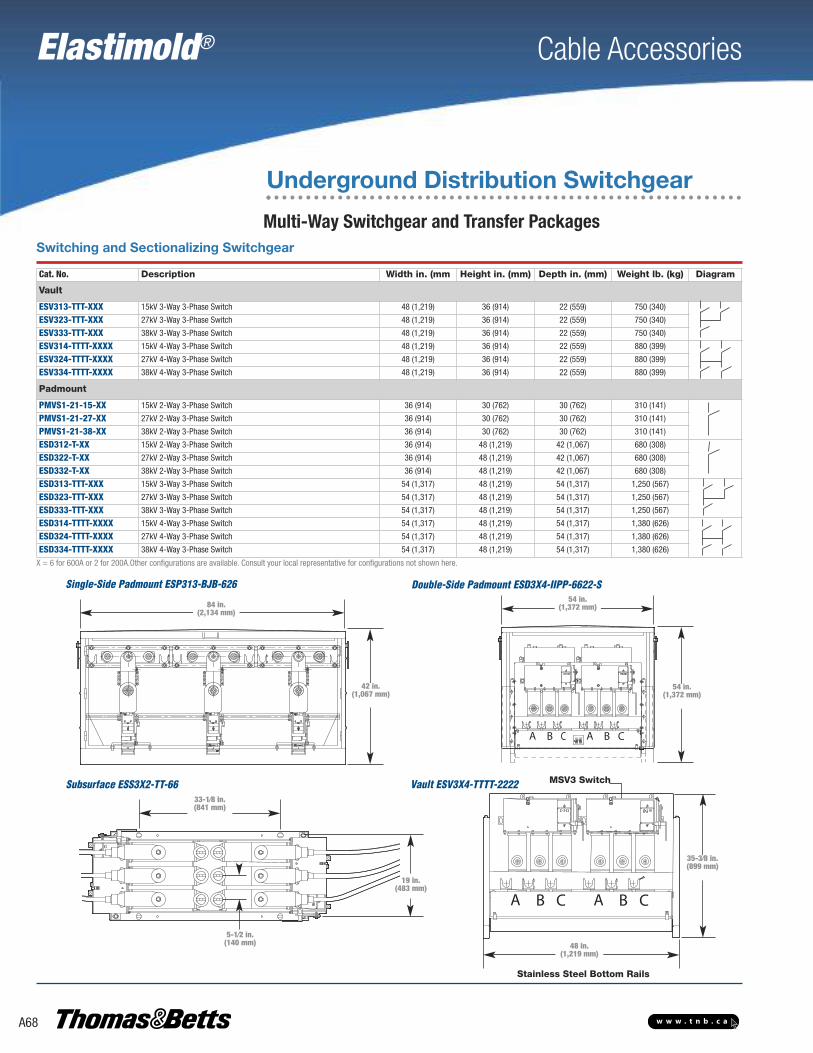
Single-Side Padmount ESP313-BJB-626
Subsurface ESS3X2-TT-66 MSV3 Switch
Stainless Steel Bottom Rails
5-1⁄2 in.(140 mm)
84 in.(2,134 mm)
42 in.(1,067 mm)
54 in.(1,372 mm)
54 in.(1,372 mm)
33-1⁄8 in.(841 mm)
19 in.(483 mm)
35-3⁄8 in.(899 mm)
48 in.(1,219 mm)
Vault ESV3X4-TTTT-2222
Cable Accessories
A68 w w w . t n b . c a
Elastimold®
Underground Distribution Switchgear
Multi-Way Switchgear and Transfer Packages
X = 6 for 600A or 2 for 200A.Other configurations are available. Consult your local representative for configurations not shown here.
Cat. No. Description Width in. (mm Height in. (mm) Depth in. (mm) Weight lb. (kg) Diagram
Vault
ESV313-TTT-XXX 15kV 3-Way 3-Phase Switch 48 (1,219) 36 (914) 22 (559) 750 (340)
ESV323-TTT-XXX 27kV 3-Way 3-Phase Switch 48 (1,219) 36 (914) 22 (559) 750 (340)
ESV333-TTT-XXX 38kV 3-Way 3-Phase Switch 48 (1,219) 36 (914) 22 (559) 750 (340)
ESV314-TTTT-XXXX 15kV 4-Way 3-Phase Switch 48 (1,219) 36 (914) 22 (559) 880 (399)
ESV324-TTTT-XXXX 27kV 4-Way 3-Phase Switch 48 (1,219) 36 (914) 22 (559) 880 (399)
ESV334-TTTT-XXXX 38kV 4-Way 3-Phase Switch 48 (1,219) 36 (914) 22 (559) 880 (399)
Padmount
PMVS1-21-15-XX 15kV 2-Way 3-Phase Switch 36 (914) 30 (762) 30 (762) 310 (141)
PMVS1-21-27-XX 27kV 2-Way 3-Phase Switch 36 (914) 30 (762) 30 (762) 310 (141)
PMVS1-21-38-XX 38kV 2-Way 3-Phase Switch 36 (914) 30 (762) 30 (762) 310 (141)
ESD312-T-XX 15kV 2-Way 3-Phase Switch 36 (914) 48 (1,219) 42 (1,067) 680 (308)
ESD322-T-XX 27kV 2-Way 3-Phase Switch 36 (914) 48 (1,219) 42 (1,067) 680 (308)
ESD332-T-XX 38kV 2-Way 3-Phase Switch 36 (914) 48 (1,219) 42 (1,067) 680 (308)
ESD313-TTT-XXX 15kV 3-Way 3-Phase Switch 54 (1,317) 48 (1,219) 54 (1,317) 1,250 (567)
ESD323-TTT-XXX 27kV 3-Way 3-Phase Switch 54 (1,317) 48 (1,219) 54 (1,317) 1,250 (567)
ESD333-TTT-XXX 38kV 3-Way 3-Phase Switch 54 (1,317) 48 (1,219) 54 (1,317) 1,250 (567)
ESD314-TTTT-XXXX 15kV 4-Way 3-Phase Switch 54 (1,317) 48 (1,219) 54 (1,317) 1,380 (626)
ESD324-TTTT-XXXX 27kV 4-Way 3-Phase Switch 54 (1,317) 48 (1,219) 54 (1,317) 1,380 (626)
ESD334-TTTT-XXXX 38kV 4-Way 3-Phase Switch 54 (1,317) 48 (1,219) 54 (1,317) 1,380 (626)
Double-Side Padmount ESD3X4-IIPP-6622-S
Switching and Sectionalizing Switchgear

Cable Accessories
A69w w w . t n b . c a
Elastimold®
Multi-Way Switchgear and Transfer Packages
Cat. No. Description Width in. (mm) Height in. (mm) Depth in. (mm) Weight lb. (kg) Diagram
Vault
ESV313-TPP-XXX 15 kV 3-Way 3-Phase (1) Source Switch, (2) Vacuum Interrupter Taps
40 (1,016) 48 (1,219) 22 (559)
660 (299)ESV323-TPP-XXX 27 kV 3-Way 3-Phase (1) Source Switch, (2) Vacuum Interrupter Taps
ESV313-TTP-XXX 15 kV 3-Way 3-Phase (2) Source Switches, (1) Vacuum Interrupter Tap
ESV323-TTP-XXX 27 kV 3-Way 3-Phase (2) Source Switches, (1) Vacuum Interrupter Tap
ESV314-TPPP-XXXX 15 kV 4-Way 3-Phase (1) Source Switch, (3) Vacuum Interrupter Taps
880 (399)
ESV324-TPPP-XXXX 27 kV 4-Way 3-Phase (1) Source Switch, (3) Vacuum Interrupter Taps
ESV314-TTPP-XXXX 15 kV 4-Way 3-Phase (2) Source Switches, (2) Vacuum Interrupter Taps
ESV324-TTPP-XXXX 27 kV 4-Way 3-Phase (2) Source Switches, (2) Vacuum Interrupter Taps
ESV314-TTTP-XXXX 15 kV 4-way 3-Phase (3) Source Switches, (1) Vacuum Interrupter Tap
ESV324-TTTP-XXXX 27 kV 4-Way 3-Phase (3) Source Switches, (1) Vacuum Interrupter Tap
Padmount
PMVI1-21-15-XX 15 kV 2-Way 1-Phase Interrupter
36 (914) 30 (762)
30 (762)
310 (141)PMVI1-21-27-XX 27 kV 2-Way 1-Phase Interrupter
PMVI1-21-38-XX 38 kV 2-Way 1-Phase Interrupter
PMVI1-21-15-XX-3YY 15 kV 2-Way 3-Phase Interrupter 1-Phase Trip Selectable Ext. Control
48 (1,219) 42 (1,067)
680 (308)
PMVI1-21-27-XX-3YY 27 kV 2-Way 3-Phase Interrupter 1-Phase Trip Selectable Ext. Control
PMVI1-21-38-XX-3YY 38 kV 2-Way 3-Phase Interrupter 1-Phase Trip Selectable Ext. Control
ESD312-P-XX 15 kV 2-Way 3-Phase (1) Vacuum Interrupter Tap
36 (914)
48 (1,219)
42 (1,067)ESD322-P-XX 27 kV 2-Way 3-Phase (1) Vacuum Interrupter Tap
ESD332-P-XX 38 kV 2-Way 3-Phase (1) Vacuum Interrupter Tap
ESD313-TPP-XXX 15 kV 3-Way 3-Phase (1) Source Switch, (2) Vacuum Interrupter Taps54 (1,372) 54 (1,372) 1,160 (526)
ESD323-TPP-XXX 27 kV 3-Way 3-Phase (1) Source Switch, (2) Vacuum Interrupter Taps
ESD333-TPP-XXX 38 kV 3-Way 3-Phase (1) Source Switch, (2) Vacuum Interrupter Taps 72 (1,829) 54 (1,372) 72 (1,829) 1,500 (680)
ESD313-TTP-XXX 15 kV 3-Way 3-Phase (2) Source Switches, (1) Vacuum Interrupter Tap54 (1,372) 48 (1,219) 54 (1,372) 1,160 (526)
ESD323-TTP-XXX 27 kV 3-Way 3-Phase (2) Source Switches, (1) Vacuum Interrupter Tap
ESD333-TTP-XXX 38 kV 3-Way 3-Phase (2) Source Switches, (1) Vacuum Interrupter Tap 72 (1,829) 54 (1,372) 72 (1,829) 1,500 (680)
ESD314-TPPP-XXXX 15 kV 4-Way 3-Phase (1) Source Switch, (3) Vacuum Interrupter Taps54 (1,372) 48 (1,219) 54 (1,372) 1,380 (626)
ESD324-TPPP-XXXX 27 kV 4-Way 3-Phase (1) Source Switch, (3) Vacuum Interrupter Taps
ESD334-TPPP-XXXX 38 kV 4-Way 3-Phase (1) Source Switch, (3) Vacuum Interrupter Taps 72 (1,829) 54 (1,372) 72 (1,829) 1,500 (680)
ESD314-TTPP-XXXX 15 kV 4-Way 3-Phase (2) Source Switches, (2) Vacuum Interrupter Taps54 (1,372) 48 (1,219) 54 (1,372) 1,380 (626)
ESD324-TTPP-XXXX 27 kV 4-Way 3-Phase (2) Source Switches, (2) Vacuum Interrupter Taps
ESD334-TTPP-XXXX 38 kV 4-Way 3-Phase (2) Source Switches, (2) Vacuum Interrupter Taps 72 (1,829) 54 (1,372) 72 (1,829) 1,500 (680)
ESD314-TTTP-XXXX 15 kV 4-Way 3-Phase (3) Source Switches, (1) Vacuum Interrupter Tap54 (1,372) 48 (1,219) 54 (1,372) 1,380 (626)
ESD324-TTTP-XXXX 27 kV 4-Way 3-Phase (3) Source Switches, (1) Vacuum Interrupter Tap
ESD334-TTTP-XXXX 38 kV 4-Way 3-Phase (3) Source Switches, (1) Vacuum Interrupter Tap 72 (1,829) 54 (1,372) 72 (1,829) 1,500 (680)
X = 6 for 600 A or 2 for 200 A.YY = 10, 20, 30, 80 for different electronic controls.Consult your Regional Sales Office on 38 kV multi-way configurations.
Underground Distribution Switchgear
Overcurrent Protection Switchgear

Cable Accessories
A70 w w w . t n b . c a
Elastimold®
Molded Fuse Products
The fastest, most cost-effective way to improve a distribution system’s reliability
Fused Elbows
Replace existing 200 A tap elbows with Elastimold® Fused Elbows to protect light-duty underground distribution systems, including sub-loops, radial taps, junctions, transformers and other equipment.
Elastimold® Fused Elbows provide full-range current-limiting fusing with 50 kA interrupting capability. They are rated for 5 kV ungrounded to 28 kV grounded Wye. Plus they provide 15/25 kV hotstick-operable, loadbreak elbow switching.
Combined Full-Range Current-Limiting Fusing 15/25 kV Hotstick-Operable, Loadbreak Elbow Switching Quickly improve the distribution system’s reliability without the expense of adding a separate piece of switchgear or replacing existing sectionalizing cabinets.
High Fault Close Rating Current-limiting fuses improve the fault close rating of the elbow (10 kA) to that of the fuse, thereby reducing the risk of component damage or personnel injury.
EPDM Molded Rubber Deadfront Construction Elbows are fully sealed and submersible, and they insulate, shield and eliminate exposed live parts.
Two-Piece Housing Enables easy fuse replacement.
Application Information• Construction: Submersible, non-venting, deadfront,
corrosion resistant• Ambient Temperature Range: -30°C to 65°C
Certified TestsElastimold® Fused Elbows have been designed and tested per applicable portions of IEEE, ANSI and other industry standards, including:ANSI C37.40 Standard for Current-Limiting Fuse Service ConditionsANSI C37.41 Standard for Current-Limiting Fuse Design and TestingANSI C37.47 Standard for Current-Limiting Fuse Ratings and SpecificationsIEEE 386 Standard for Separable Connectors
Ratings
System Voltage Class (kV) 15 25* 25/28*
Nominal Fuse Voltage (kV) 8.3 15.5 17.2
Rated Maximum Fuse Voltage (kV) 8.8/10 15.5 17.2
Frequency (Hz) 50/60 50/60 50/60
BIL Impulse Withstand (kV) 95 125 140
One-Minute AC Withstand (kV) 34 40 45
Fifteen-Minute DC Withstand (kV) 53 78 78
Corona Extinction (kV) 11 19 21.5
Symmetrical Interrupting Capability (Amp) 50,000 50,000 50,000
Current Rating (Amp) 3–80 6–20 3–45
* The 15.5 kV L-G rated fuse requires 75% grounded load to be applied on a 25 kV system.The 17.2 kV L-G rated fuse requires at least 75% grounded load to be applied on a 28 kV system.
Fuses are only suitable for the system voltage class shown if the recovery voltage across the fuse will not exceed its rated maximum voltage. For three-phase applications, this generally requires that protected transformers be gndY–gndY and have at least 50% grounded load. Fuse replacement requiresthe elbow to be de-energized.
Lower ElbowHalf
Hose Clamp
Crimp Lug
Fuse
Probe Lug
Upper ElbowHalfProbe
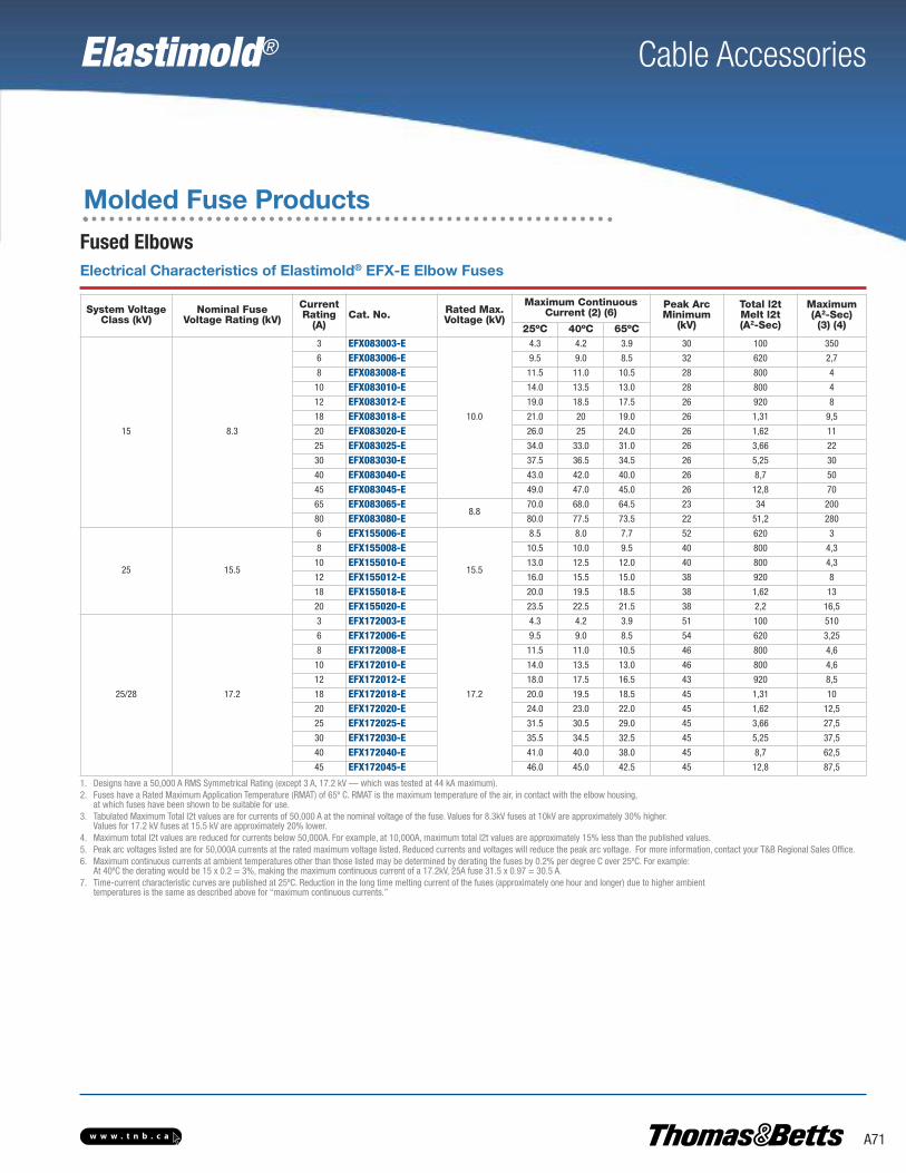
Cable Accessories
A71w w w . t n b . c a
Elastimold®
Molded Fuse Products
Fused Elbows
1. Designs have a 50,000 A RMS Symmetrical Rating (except 3 A, 17.2 kV — which was tested at 44 kA maximum).2. Fuses have a Rated Maximum Application Temperature (RMAT) of 65º C. RMAT is the maximum temperature of the air, in contact with the elbow housing,
at which fuses have been shown to be suitable for use.3. Tabulated Maximum Total I2t values are for currents of 50,000 A at the nominal voltage of the fuse. Values for 8.3kV fuses at 10kV are approximately 30% higher.
Values for 17.2 kV fuses at 15.5 kV are approximately 20% lower. 4. Maximum total I2t values are reduced for currents below 50,000A. For example, at 10,000A, maximum total I2t values are approximately 15% less than the published values.5. Peak arc voltages listed are for 50,000A currents at the rated maximum voltage listed. Reduced currents and voltages will reduce the peak arc voltage. For more information, contact your T&B Regional Sales Office.6. Maximum continuous currents at ambient temperatures other than those listed may be determined by derating the fuses by 0.2% per degree C over 25ºC. For example:
At 40ºC the derating would be 15 x 0.2 = 3%, making the maximum continuous current of a 17.2kV, 25A fuse 31.5 x 0.97 = 30.5 A.7. Time-current characteristic curves are published at 25ºC. Reduction in the long time melting current of the fuses (approximately one hour and longer) due to higher ambient
temperatures is the same as described above for “maximum continuous currents.”
System Voltage Class (kV)
Nominal Fuse Voltage Rating (kV)
Current Rating(A)
Cat. No. Rated Max.Voltage (kV)
Maximum Continuous Current (2) (6)
Peak ArcMinimum
(kV)
Total l2t Melt l2t(A2-Sec)
Maximum(A2-Sec)(3) (4)25ºC 40ºC 65ºC
15 8.3
3 EFX083003-E
10.0
4.3 4.2 3.9 30 100 350
6 EFX083006-E 9.5 9.0 8.5 32 620 2,7
8 EFX083008-E 11.5 11.0 10.5 28 800 4
10 EFX083010-E 14.0 13.5 13.0 28 800 4
12 EFX083012-E 19.0 18.5 17.5 26 920 8
18 EFX083018-E 21.0 20 19.0 26 1,31 9,5
20 EFX083020-E 26.0 25 24.0 26 1,62 11
25 EFX083025-E 34.0 33.0 31.0 26 3,66 22
30 EFX083030-E 37.5 36.5 34.5 26 5,25 30
40 EFX083040-E 43.0 42.0 40.0 26 8,7 50
45 EFX083045-E 49.0 47.0 45.0 26 12,8 70
65 EFX083065-E8.8
70.0 68.0 64.5 23 34 200
80 EFX083080-E 80.0 77.5 73.5 22 51,2 280
25 15.5
6 EFX155006-E
15.5
8.5 8.0 7.7 52 620 3
8 EFX155008-E 10.5 10.0 9.5 40 800 4,3
10 EFX155010-E 13.0 12.5 12.0 40 800 4,3
12 EFX155012-E 16.0 15.5 15.0 38 920 8
18 EFX155018-E 20.0 19.5 18.5 38 1,62 13
20 EFX155020-E 23.5 22.5 21.5 38 2,2 16,5
25/28 17.2
3 EFX172003-E
17.2
4.3 4.2 3.9 51 100 510
6 EFX172006-E 9.5 9.0 8.5 54 620 3,25
8 EFX172008-E 11.5 11.0 10.5 46 800 4,6
10 EFX172010-E 14.0 13.5 13.0 46 800 4,6
12 EFX172012-E 18.0 17.5 16.5 43 920 8,5
18 EFX172018-E 20.0 19.5 18.5 45 1,31 10
20 EFX172020-E 24.0 23.0 22.0 45 1,62 12,5
25 EFX172025-E 31.5 30.5 29.0 45 3,66 27,5
30 EFX172030-E 35.5 34.5 32.5 45 5,25 37,5
40 EFX172040-E 41.0 40.0 38.0 45 8,7 62,5
45 EFX172045-E 46.0 45.0 42.5 45 12,8 87,5
Electrical Characteristics of Elastimold® EFX-E Elbow Fuses

Cable Accessories
A72 w w w . t n b . c a
Elastimold®
Molded Fuse Products
Fused Elbows
1. Column A = 140–200% of transformer rating and Column B = 200–300% of transformer rating.2. Ratings in parenthesis are 17.2 kV fuses.3. 8.3 kV, 3–45 A fuses and 15.5 kV, 6–20A fuses are used in the small (size 1) elbow housing; 8.3 kV, 65–80 A fuses and 17.2 kV, 3–45 A fuses are used in the large (size 3) elbow fuse housing.4. Recommended fuses meet inrush criteria of 12 times transformer full-load current for 0.1 second and 25 times transformer full-load current for 0.01 second.
Fuses also meet cold-load pickup criteria of 6 times transformer full-load current for 1 second and 3 times transformer full-load current for 10 seconds.
a. Fuse allows greater than 300% of transformer rating.
Recommended Elastimold® EFX-E Elbow Fuse at 40ºC Ambient Temperature
Recommended Fuse Current Ratings (Amperes)
Fuse Voltage 8.3 kV 15.5 kV (17.2 kV)
1-PhaseTransformer
kVA
Transformer 1-Phase Voltage Rating (kV), Phase to Ground
2.4 4.16 4.8 7.2 7.62 12 14.4 16A B A B A B A B A B A B A B A B
10 — 6 — 6a — 3 — 3 — 3 — 6a — 6a — (3a)
15 — 10 — 6 — 6a — 3 — 3 — 6a — 6a — (3a)
25 12 20 — 8 — 8 — 6 — 6 — 6a — 6a — -3
37.5 20 25 — 12 — 12 — 8 — 6 — 6 — 6a — (6a)
50 25 40 18 20 12 20 10 12 — 10 — 6 — 6 — (6a)
75 45 65 20 30 20 25 12 20 12 18 — 10 — 8 — -8
100 65 80 30 45 25 40 18 25 18 25 12 18 10 12 — -10
167 — — 65 80 45 65 25 45 25 45 18 -25 18 20 -12 -20
250 — — 80 — 80 — 45 65 45 65 -25 -45 20 -30 -20 -30
333 — — — — — — 65 — 80 — -40 — -30 -45 -25 -45
500 — — — — — — — — — — — — -45 — -45 —
Recommended Elastimold® EFX-E Elbow Fuse at 40ºC Ambient Temperature
Recommended Fuse Current Ratings (Amperes)
Fuse Voltage 8.3 kV 15.5 kV (17.2 kV)
1-PhaseTransformer
kVA
Transformer 1-Phase Voltage Rating (kV), Phase to Ground
2.4 4.16 4.8 7.2–7.96 8.32 12.47 13.2–14.4 20.8 22.9–24.9A B A B A B A B A B A B A B A B A B
15 — 6 — 3 — 3 — 3a — 3a — 6a — 6a — 6a — (3a)
22.5 — 8 — 6a — 6a — 3 — 3 — 6a — 6a — 6a — (3a)
30 10 12 — 6 — 6 — 6a — 3 — 6a — 6a — 6a — (3a)
45 12 20 — 10 — 8 — 6 — 6a — 6a — 6a — 6a — (3a)
75 20 30 12 20 — 12 — 8 — 8 — 6 — 6 — 6a — -3
100 30 45 18 25 18 20 — 12 — 10 — 8 — 8 — 6a — (6a)
112.5 40 65 20 25 18 25 — 12 — 12 — 8 — 8 — 6 — (6a)
150 45 80 25 40 20 30 18 20 12 20 10 12 10 12 — 6 — -6
200 65 80 40 65 30 45 20 25 18 25 12 18 12 18 8 10 — -8
225 80 — 45 65 40 65 20 30 20 25 12 20 12 18 8 10 — -10
300 — — 65 80 45 80 30 45 25 40 18 25 18 25 12 18 — -12
500 — — — — 80 — 65 80 45 80 30 45 30 45 18 -25 -18 -25
750 — — — — — — 80 — 80 — 45 65 45 — -25 -45 -25 -40
1 — — — — — — — — — — 80 — — — -40 — -40 —

Cable Accessories
A73w w w . t n b . c a
Elastimold®
Molded Fuse Products
Full-Range Molded Current-Limiting FusesThe following diagram shows how to construct a catalogue number for Fuse Housings and Full-Range Current-Limiting Fuses.
Indicates field that must be filled in to complete order.
Voltage Rating
083 8.3 kV
155 15.5 kV
172 17.2 kV
Amperage Rating
003 8.3/17.2 kV 3 A
006 8.3/15.5/17.2 kV 6 A
008 8.3/15.5/17.2 kV 8 A
010 8.3/15.5/17.2 kV 10 A
012 8.3/15.5/17.2 kV 12 A
018 8.3/15.5/17.2 kV 18 A
020 8.3/15.5/17.2 kV 20 A
025 8.3/17.2 kV 25 A
030 8.3/17.2 kV 30 A
040 8.3/17.2 kV 40 A
045 8.3/17.2 kV 45 A
065 8.3 kV 65 A
080 8.3 kV 80 A
E F X E8.3 kV (3–45 A)/15.5 kV (6–20 A) Fuse
8.3 kV (65–80 A)/17.2 kV (3–45 A) Fuse
All dimensions rounded up to the nearest eighth inch.
13-1/2 in.(343 mm)
9-1/4 in.(235 mm)
2-1/4 in.(54 mm)
2-1/4 in.(54 mm)
Indicates field that must be filled in to complete order.
Nominal FuseVoltage Rating
168 8.3 kV
274 15.5 kV
274 17.2 kV
Conductor Size
180 6 –
190 – 4
200 4 –
210 – 2
220 2 1
230 1 1/0
240 1/0 2/0
250 2/0 3/0
260 3/0 4/0
270 4/0 –
Fuse Test Port
A Two Direct Test Ports
Blank Two Capacitive Test Points
Housing
1 Small
3 Large**
Cable Insulation Diameter (in.)
A 0.575 in.–0.740 in. 15–19 mm
B 0.635 in.–0.905 in. 16–23 mm
C 0.805 in.–1.060 in. 20–27 mm
D 0.890 in.–1.220 in. 25–31 mm
F L R Ø
* Small Housing is used with 8.3kV (3–45A) and 15.5kV (6–20A) rated fuses.** Large Housing is used with 8.3kV (65A and 80A) and 17.2kV (3–45A) rated fuses.
1. All dimensions rounded up to the nearest eighth inch.2. Also available with direct test port.3. Dimensions with Direct Test Port units are 10-1⁄4 in. (260 mm) or 10-5⁄8 in. (270 mm).4. 168FLR3 uses a large housing with a 15 kV, 200 A elbow interface.
168FLR1 274FLR1 168FLR3274FLR3
6-1⁄4 in.(159 mm)
10-5⁄8 in.(270 mm)
6-1⁄4 in.(159 mm)
10-5⁄8 in.(270 mm)
9-1⁄4 in.(235 mm)
A
10-5⁄8 in.(270 mm)
10-1⁄2 in.(270 mm)
A = 8-7⁄8 in. (225 mm)A = 9-1⁄4 in. (235 mm)
8-7⁄8 in.(225 mm)

Cable Accessories
A74 w w w . t n b . c a
Elastimold®
Molded Fuse Products
Full-Range Molded Current-Limiting Fuses
Application InformationConstruction: Submersible, non-venting, deadfront, corrosion resistantAmbient Temperature Range: • -30°C to 65°C for 6–50 A fuses;• -30°C to 40°C for >50 A fuses.
Certified TestsElastimold® Molded Current-Limiting Fuses have been designed andtested per applicable portions of IEEE, ANSI, NEMA and other industrystandards, including:ANSI C37.40 Standard for Current-Limiting Fuse Service ConditionsANSI C37.41 Standard for Current-Limiting Fuse Design and TestingANSI C37.47 Standard for Current-Limiting Fuse Ratings and SpecificationsANSI/IEEE 386 Standard for Separable Connectors and Bushing Interfaces
Ratings
System Voltage Class (kV) 5 15 25/28* 35
Rated Maximum Fuse Voltage (kV) 5.5 8.3/10** 15.5/17.2** 23
Frequency (Hz) 50/60 50/60 50/60 50/60
BIL Impulse Withstand (kV) 60 95 125/140 150
One-Minute AC Withstand (kV) 34 34 40–45 50
Fifteen-Minute DC Withstand (kV) 53 53 78 103
Corona Extinction (kV) 11 11 19/21.5 26
Symmetrical Interrupting Capability (A) 50 50 50 50
Current Rating (A) 80–180 10–115 10–100 10–50
* 15.5 kV L-G rated fuses require 75 % grounded load to be applied on a 25 kV system.** 17.2 kV L-G rated fuses require at least 75 % grounded load to be applied on a 28 kV system.
Fuse replacement requires the MCLF to be de-energized.Fuses are only suitable for the system voltage class shown if the recovery voltage across the fuse will notexceed its rated maximum voltage. For three-phase applications, this generally requires that protectedtransformers be gndY-gndY and have at least 50 % grounded load.
Interchangeable Molded Rubber End Fittings
Assembled Fuse Unit
Replaceable Molded Rubber Current-Limiting Fuse
Assembled Fuse Unit with Optional Wall-Mounting Bracket

Elastimold® Cable Accessories
A75w w w . t n b . c a
Molded Fuse Products
Full-Range Molded Current-Limiting Fuses
1. Designs have a 50,000 A all U/CERMSs Symmetrical Rating.2. 10–50 A fuses have a Rated Maximum Application Temperature of 65°C, and 65–180 A fuses have a Rated Maximum Application Temperature of 40°C.
(RMAT is the maximum temperature of the air in contact with the MCLF housing at which the fuses have been shown suitable for use.)3. Tabulated Maximum Total I2t values are for currents of 50,000 A at the nominal voltage of the fuse. Fuses that have a Rated Maximum Voltage higher than their Nominal Voltage Rating will
have a higher I2t let-through when applied at voltages up to these higher values. For example, Maximum Total I2t values are increased by approximately 30% when 8.3 kV fuses are applied at 10kV and approximately 25% when 15.5kV fuses are used at 17.2 kV.
4. Maximum total l2t values are reduced for currents below 50,000 A. For example, at 10,000 A, l2t values are approximately 15% less than the published values.5. Peak arc voltages quoted are for 50,000A currents at the rated maximum voltage listed. Reduced currents and voltages will reduce the peak arc voltage. Consult the factory for further information.6. Maximum continuous currents at higher ambient temperatures may be determined by derating the fuses by 0.2% per degree C over 25° C.
For example: At 40°C, the derating would be 15 x 0.2 = 3%, making the maximum continuous current of a 20 A fuse 23.0 x 0.97 = 22 A.
Electrical Characteristics of Encapsulated Fuses Used in MCLF
Nominal Fuse Voltage Rating
(kV)
CurrentRating(A)
FuseCatalogueNumber
RatedMaximumVoltage(kV)
MaximumContinuousCurrent(2) (6)
Peak ArcTotal l2t (kV) (5)
Minimum Melt l2t(A2–Sec)
Maximum Totall2t
(A2–Sec)(3) (4)
25°C 40°C
5.5
80 M05CLF080
5.5
86 84
15
22,100 110,000
100 M05CLF100 108 105 56,700 280,000
125 M05CLF125 137 133 109,200 530,000
150 M05CLF150 159 154 176,000 860,000
180 M05CLF180 185 180 259,000 1,270,000
8.3
10 M15CLF010
10.0
14 13 28 800,000 4,000
20 M15CLF020 23 22
26
1,620 11,000
30 M15CLF030 35 33 5,250 30,000
40 M15CLF040 43 41 8,700 50,000
50 M15CLF050 51 47 12,800 70,000
65 M15CLF065
8.3
73 71
25
25,200 100,000
80 M15CLF080 87 84 47,000 185,000
100 M15CLF100 106 103 78,300 330,000
115 M15CLF115 120 116 115,150 480,000
15.5
10 M25CLF010
17.2
14 13 46 800,000 3,700
20 M25CLF020 23 22
45
1,620 10,000
30 M25CLF030 35 33 5,250 30,000
40 M25CLF040 43 41 8,700 50,000
50 M25CLF050 47 45 12,800 70,000
65 M25CLF06515.5
68 66
40
25,200 110,000
80 M25CLF080 88 84 54,400 255,000
100 M25CLF100 100 100 80,000 380,000
23.0
10 M35CLF010
23.0
14 13 61 800,000 4,800
20 M35CLF020 23 22
60
1,620 13,000
30 M35CLF030 35 33 5,250 38,000
40 M35CLF040 41 40 8,700 61,000
50 M35CLF050 47 46 12,800 82,000
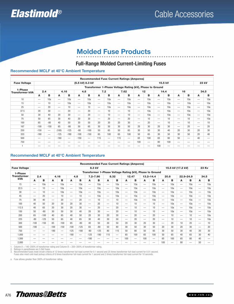
Elastimold® Cable Accessories
A76 w w w . t n b . c a
Molded Fuse Products
Full-Range Molded Current-Limiting FusesRecommended MCLF at 40°C Ambient Temperature
Recommended Fuse Current Ratings (Amperes)
Fuse Voltage (5.5 kV) 8.3 kV 15.5 kV 23 kV
1-PhaseTransformer kVA
Transformer 1-Phase Voltage Rating (kV), Phase to Ground
2.4 4.16 4.8 7.2 7.62 12 14.4 16 34.5A B A B A B A B A B A B A B A B A B
10 — 10a — 10a — 10a — 10a — 10a — 10a — 10a — 10a — 10a
15 — 10 — 10a — 10a — 10a — 10a — 10a — 10a — 10a — 10a
25 — 20 — 10 — 10 — 10a — 10a — 10a — 10a — 10a — 10a
37.5 20 30 — 20 — 20 — 10 — 10 — 10a — 10a — 10a — 10a
50 30 40 20 30 — 20 — 10 — 10 — 10a — 10a — 10a — 10a
75 50 65 30 40 20 30 — 20 — 20 — 10 — 10 — 10 — 10a
100 65 -80 40 50 30 50 20 30 20 30 — 20 — 10 — 10 — 10
167 -100 -150 65 -80 50 65 30 50 30 50 20 30 20 30 — 20 — 20
250 -150 — (100) -125 -80 -100 50 65 50 65 30 50 30 40 20 30 20 30
333 -180 — -125 -180 -100 -150 65 100 65 100 50 65 30 50 30 50 20 40
500 — — -180 — -150 — 115 — 115 — 65 100 65 80 50 — 40 —
750 — — — — — — — — — — 100 — 80 100 — — — —
1 — — — — — — — — — — — — 100 — — — — —
1. Column A = 140–200% of transformer rating and Column B = 200–300% of transformer rating.2. Ratings in parentheses are 5.5kV fuses.3. Recommended fuses meet inrush criteria of 12 times transformer full-load current for 0.1 second and 25 times transformer full-load current for 0.01 second.
Fuses also meet cold-load pickup criteria of 6 times transformer full-load current for 1 second and 3 times transformer full-load current for 10 seconds.
a. Fuse allows greater than 300% of transformer rating.
Recommended Fuse Current Ratings (Amperes)
Fuse Voltage 8.3 kV 15.5 kV (17.2 kV) 23 Kv
1-PhaseTransformer
kVA
Transformer 1-Phase Voltage Rating (kV), Phase to Ground
2.4 4.16 4.8 7.2–7.96 8.32 12.47 13.2–14.4 20.8 22.9–24.9 34.5A B A B A B A B A B A B A B A B A B A B
15 — 10a — 10a — 10a — 10a — 10a — 10a — 10a — 10a — 10a — 10a
22.5 — 10 — 10a — 10a — 10a — 10a — 10a — 10a — 10a — 10a — 10a
30 — 10 — 10a — 10a — 10a — 10a — 10a — 10a — 10a — 10a — 10a
45 — 20 — 10 — 10 — 10a — 10a — 10a — 10a — 10a — 10a — 10a
75 30 40 — 20 — 20 — 10 — 10 — 10a — 10a — 10a — 10a — 10a
100 40 50 20 30 20 30 — 20 — 10 — 10 — 10 — 10a — 10a — 10a
112.5 40 65 20 30 20 30 — 20 — 20 — 10 — 10 — 10a — 10a — 10a
150 50 -80 30 50 30 40 20 30 — 20 — 10 — 10 — 10a — 10a — 10a
200 65 -100 40 65 40 50 20 30 20 30 — 20 — 20 — 10 — 10 — 10a
225 -80 -125 50 65 40 65 30 40 30 50 — 20 — 20 — 10 — 10 — 10a
300 -100 -150 65 -100 65 -80 40 50 30 50 20 30 20 30 — 20 10 20 — 10
500 -180 — -100 -150 -100 -125 65 -80 50 80 30 50 30 50 20 30 20 30 — 20
750 — — -180 — -125 -180 -80 -125 80 115 50 80 50 65 30 50 30 40 20 30
1,000 — — — — -180 — -125 -180 115 — 65 100 65 100 50 65 40 65 30 40
1,500 — — — — — — -180 — — — 100 — 100 — 65 100 65 80 40 —
2,000 — — — — — — — — — — — — — — 100 — 80 — 50 —
Recommended MCLF at 40°C Ambient Temperature

Elastimold® Cable Accessories
A77w w w . t n b . c a
Molded Fuse Products
Full-Range Molded Current-Limiting Fuses
Approx. Weight 30 lb. (13.6 kg)
16-5⁄8 in." (422mm)
19-1⁄2 in. (343 mm)
5-1⁄8 in.(130 mm)
8-3⁄16 in.(208 mm)
8-3⁄16 in.(208 mm)
9-3⁄16 in.(233 mm)
4 in.(102 mm)
16-5⁄8 in. (422 mm)
16-5⁄8 in. (422 mm)
23-5⁄8 in. (343 mm)
27-5⁄8 in. (702 mm)
5-1⁄8 in.(130 mm)
5-1⁄8 in.(130 mm)
4 in.(102 mm)
4 in.(102 mm)
16-5⁄8 in. (422 mm)
19-5⁄8 in. (498 mm)
5-1⁄8 in.(130 mm)
9/16 in.(233 mm)
Model 22
Model 222
Model 2222
Model 66
Model 6E2
Approx. Weight 35 lb. (15.9 kg)
Approx. Weight 30 lb. (13.6 kg)
Approx. Weight 40 lb. (18.1 kg)
Approx. Weight 30 lb. (13.6 kg)
Lifting Eye
9⁄16 in. (14 mm) x 1 in.(25 mm) Mounting Slots on 5-1⁄2 in. (140 mm) Centers
2-3⁄4 in.(70 mm)
3⁄4 in. (19 mm)11-1⁄8 in.(283 mm) 6-3⁄8 in.
(162 mm)
18-5⁄8 in.(473 mm)
22-1⁄2 in.(572 mm)
5-1⁄8 in.(130 mm)

Elastimold® Cable Accessories
A78 w w w . t n b . c a
Molded Fuse Products
Full-Range Molded Current-Limiting Fuses
Other models are available such as 26.
11-1⁄8 in.(283 mm)
9⁄16 in. (14 mm) x 1 in. (25 mm) Mounting Slots on
5-1⁄2 in. (140 mm) Centers
Lifting Eye
5-1⁄8 in.(130 mm)
2-3⁄4 in.(70 mm)
6-3⁄8 in.(162 mm)
22-1⁄2 in.(572 mm)
18-5⁄8 in.(473mm)
1⁄2 in.(13 mm)
Model 6E6
Approx. Weight 30 lb. (13.6kg)
The following diagram shows how to construct a catalog number for a Molded Current-Limiting Fuse:
Indicates field that must be filled in to complete order.
See page A75 for additional options.
See page A75 for additional options.
See outline drawings preceding this chart for additional details.
Voltage Class
5 5.0 kV
15 15.0 kV
25 25.0 kV
35 35.0 kV
Amperes
5 kV 15 kV 25 kV 35 kV
10 — 10 10 10
20 — 20 20 20
30 — 30 30 30
50 — 40 40 40
65 — 50 50 50
80 — 65 65 —
100 80 80 80 —
115 100 100 100 —
125 — 115 — —
150 125 — — —
200 150 — — —
Mounting Brackets
WMB Wall Mounting Bracket with Parking Stands andBolted Style Hold Down Straps (HDS)
WMBQ Wall Mounting Bracket with Parking Stands andQuick Release Style Hold Down Straps (QRS)
M C L F
Bushings
22 200 A Bushing Wells both ends
222 200 A Bushing Well on one end and two 200 A Bushing Wells on the other end
2222 Two 200 A Bushing Wells on both ends
66 600 A Bushings on both ends
6E2 600 A Elbow Connector on one end and a 600 A Bushing onthe other end; this arrangement is not available at 35 kV 6E6
See page A79 for additional options.

Elastimold® Cable Accessories
A79w w w . t n b . c a
15 to 60˚
Approx. Weight 8 lb. (3.6 kg) 9/16 in. (14 mm) x 1 in. (25 mm)Mounting Slots
6-3/4 in.(171 mm)
Optional WMB Mounting Bracket with AdjustableParking Stands for Vertical Mounting and Fuse Hold-Down Strips
Optional — TMA Universal Tilt Mounting
5-1/2 in.(140 mm)
Mounting Options
29-3/4 in. (756 mm)
32-3/4 in. (832 mm)
Option No. DescriptionHDS Bolted-Style Hold-Down Strap (Qty: 1 required per end fitting)QRS Quick-Release Style Hold-Down Strap (Qty: 1 required per end fitting)WMB Wall-Mounting Bracket with Parking Stands and Bolted-Style Hold-Down StrapsWMBQ Wall-Mounting Bracket with Parking Stands and Quick-Release Style Hold-Down StrapsSMB Support Mounting Bracket for use with Models 6E2 or 6E6 end-fitting arrangements includes Bolted-Style Hold-Down StrapTMA-EM Tilt Mounting Adapter bolts to bottom of Wall-Mounting Bracket WMB or WMBQ to enable up to 60º angle mounting (Qty: 2 required per installation)
Optional Fuse Mountings
Option No. Description System Voltage Class IEEE 386-1995 Interface ReferenceEF2 200 A Bushing Well End Fitting 5, 15, 25, 35 Figure 3
EF22 Double 200 A Bushing Well End Fitting 5, 15, 25, 35 Figure 3
EF6 600 A Bushing End Fitting 5, 15, 25, 35 Figures 11 and 13EF6E 600 A Elbow Connector End Fitting 5, 15, 25 Figure 11
End Fitting Catalogue Numbers
Option No. DescriptionMCLF-ADT Hex Wrench for set screw removal and replacement when disassembling end fittings. Supplied as standard with replacement fuses.
Assembly/Disassembly Tool
3/8 in. (10 mm)Sq. Drive
3/16 in. (5 mm) Hex
Other Options
Molded Fuse Products
Full-Range Molded Current-Limiting Fuses
The option number may be added as a suffix to the MCLF catalogue number.
EF6E is equipped with a standard through-hole spade lug (Type 03700).Use this table only if end fittings are to be ordered and shipped separately from the fuse. See pages A77-A78 for assembled units.

Elastimold® Cable Accessories
A80 w w w . t n b . c a
Surge Arresters
Metal Oxide Varistor (MOV) Surge ArrestersFully shielded, fully submersible for convenient energized connection with 200 A loadbreak or deadbreak components up to 35 kV
Voltage surges that exceed the BIL rating of the distribution system components will cause damage to the installed equipment. To protect against these surges, overhead surge arresters are
widely used. Their application is understood since overhead lines and equipment aredirectly affected by voltage surges (e.g. lightning). However, the use of overhead
arresters alone will not guarantee proper protection of the insulation inthe underground portion of an electrical distribution system. The
let through surge from the riser pole arresters into the underground systems could be enough to cause damage tothe aging equipment insulation.
Elastimold® MOV Surge Arresters provide high-voltage lightning and switching surge protection of transformers,
cable, equipment and other components typically located onunderground power distribution systems. Proper placement,
voltage selection and coordination with riser pole arresters minimize damaging surge voltages by improving protective margins.
Typical applications include installing an arrester at the end of a radial system or at both ends of an open point on a loop system. Additional arresters can be added at strategic locations upstream from the end pointfor optimum protection.
Metal Oxide Varistor (MOV) Surge Arresters are available in three styles:Elbow (ESA), Parking Stand (PSA) and Bushing (BSA). The PSA and BSA
arresters permit direct connection, eliminating the need for additional accessories. ESA Elbow Arresters are also available with a 200 A deadbreak
interface for mating with other deadbreak accessories.
The following page highlights the different installation options using Bushing and Parking StandArresters where Elbow Arresters are normally used. Using BSAs and PSAs will contribute to saving space inside transformers and improving operability.
IEEE 386 Interfaces; IEEE C62.11 Provide convenient energizedconnection with other 200 A loadbreak or deadbreak components.EPDM Molded Rubber Construction Fully shielded and fully submersible for a variety of applications.Compact Size Enables installation in your existing cabinetry, saving you money.Three Styles of Arresters Available Surge arresters fit your application and are easy to install.Direct Connection on PSA and BSA Versions Eliminates the needfor additional accessories, saving even more money.#4 AWG Ground Lead Tethered to the Jacket Withstands 10,000 A for 10 cycles without fusing. Controls end plug when ejected, preventing uncontrolled trajectory. Maintains the housingshield ground connection after failure.
Ratings
High Current, Short Duration All MOV Arresters withstand two discharges of 40 kA crest
Low Current, Long Duration All MOV Arresters withstand 20 surges of 75 A/2,000 microseconds duration
Duty Cycle Test
All MOV Arresters withstand 22 operations of 5 kA crest at 8 x20 microseconds duration while energized at rated voltage for the initial 20 operations and at maximum continuous operating voltage (MCOV) for the final two operations
Following each of the preceding tests, MOV Arresters demonstrate thermal recovery at MCOV.
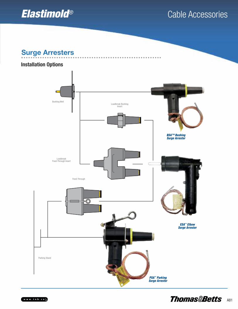
Elastimold® Cable Accessories
A81w w w . t n b . c a
Surge Arresters
Installation Options
PSA™ ParkingSurge Arrester
BSA™ Bushing Surge Arrester
Loadbreak BushingInsert
LoadbreakFeed-Through Insert
Parking Stand
Feed-Through
Bushing Well
ESA™ Elbow Surge Arrester

Elastimold® Cable Accessories
A82 w w w . t n b . c a
Surge Arresters
Loop-Feed Circuit (Type 2 Transformer)
This is one approach usingelbow arresters only. (One ofthe elbow arresters could be mounted on the H1Abushing if operating procedures permit.)
This approach is best for increasing operability and reducing transformerovercrowding. The bushing arrester enables the source cable to be positioned on H1A, which conforms with some operating practices. A bushing arrester mounted on H1A can be directed downward without interference. Potential interference between an elbow arrester on H1B and acable parked on P is eliminated. The bushing arrester requires significantlyless space than an elbow arrester used with a feed-through insert. Operability is enhanced because the open point can be closed by moving theparked cable to H1B without removing an arrester.
An additional margin of protection may be gained byadding an arrester at the next transformer upstream oneach side of the open point. This application is depen-dent on the system voltage and condition of the cable.
If an additional arrester is added in the circuit, it canbe an elbow arrester in combination with a feed-through insert or it can be a bushing arrester. Use of abushing arrester will reduce transformer faceplateovercrowding.
Other configurations are possible, such as specifying a bushing arrester on every transformer. This enables the open point to be quickly and ea-sily moved to any point in the circuit while maintaining the surge protection (without moving all of the portable surge arresters). The externallymounted bushing arrester provides the surge protection benefits without the negative factors of an under-oil arrester.
* Transformers must be specified with bushing wells.
This approach can reduceovercrowding (by eliminating the feed-through device). Thisis desirable in a mini-padtransformer.
Bushing Arrester and Parking Stand Arrester*
Additional Margin of Protection
Other Configurations
Elbow Arrester andParking Stand Arrester
Two Elbow Arresters and a Feed-Through
OR
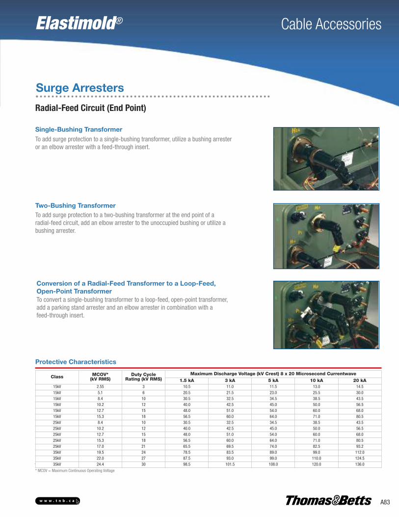
Elastimold® Cable Accessories
A83w w w . t n b . c a
Surge Arresters
Radial-Feed Circuit (End Point)
To add surge protection to a single-bushing transformer, utilize a bushing arresteror an elbow arrester with a feed-through insert.
Single-Bushing Transformer
To add surge protection to a two-bushing transformer at the end point of a radial-feed circuit, add an elbow arrester to the unoccupied bushing or utilize abushing arrester.
To convert a single-bushing transformer to a loop-feed, open-point transformer,add a parking stand arrester and an elbow arrester in combination with a feed-through insert.
Two-Bushing Transformer
Conversion of a Radial-Feed Transformer to a Loop-Feed, Open-Point Transformer
Class MCOV*(kV RMS)
Duty CycleRating (kV RMS)
Maximum Discharge Voltage (kV Crest) 8 x 20 Microsecond Currentwave1.5 kA 3 kA 5 kA 10 kA 20 kA
15kV 2.55 3 10.5 11.0 11.5 13.0 14.515kV 5.1 6 20.5 21.5 23.0 25.5 30.015kV 8.4 10 30.5 32.5 34.5 38.5 43.515kV 10.2 12 40.0 42.5 45.0 50.0 56.515kV 12.7 15 48.0 51.0 54.0 60.0 68.015kV 15.3 18 56.5 60.0 64.0 71.0 80.525kV 8.4 10 30.5 32.5 34.5 38.5 43.525kV 10.2 12 40.0 42.5 45.0 50.0 56.525kV 12.7 15 48.0 51.0 54.0 60.0 68.025kV 15.3 18 56.5 60.0 64.0 71.0 80.525kV 17.0 21 65.5 69.5 74.0 82.5 93.235kV 19.5 24 78.5 83.5 89.0 99.0 112.035kV 22.0 27 87.5 93.0 99.0 110.0 124.535kV 24.4 30 98.5 101.5 108.0 120.0 136.0
Protective Characteristics
* MCOV = Maximum Continuous Operating Voltage

Elastimold® Cable Accessories
A84 w w w . t n b . c a
Surge Arresters
MOV Surge ArrestersTo specify and order an MOV Surge Arrester:
1) Determine the appropriate Maximum Continuous Operating Voltage (MCOV) for your system voltage using the Arrester Application Table below.
2) Specify the appropriate Elastimold® catalogue number from the Selection Chart.
15 kVClass
System Line-to-LineVoltage kVrms MCOV* kV RMS
Nominal Maximum
SolidlyGrounded NeutralCircuits
3-Wire UngroundedCircuits
2.40 2.54 2.55 2.554.16 4.40 2.55 5.104.80 5.08 5.10 5.106.90 7.26 5.10 8.408.32 8.80 5.10 8.40
12.47 13.20 8.40 15.3013.20 13.97 8.40 15.3013.80 14.50 8.40** 15.3013.80 14.50 10.20 15.30
25 kVClass
6.90 7.26 5.10 8.408.32 8.80 5.10 8.40
12.47 13.20 8.40 15.3013.20 13.97 8.40 15.3013.80 14.50 8.40** 15.3013.80 14.50 10.20 15.3020.78 22.00 12.70 —20.78 22.00 15.30** —23.00 24.34 15.30 —24.94 26.40 15.30 —24.94 26.40 17.00** —28.00 29.80 17.00 —
Arrester Application Table
Cat. No. Description VoltageClass
MCOVkV RMS Picture
167BSA-3
BSA Bushing Surge Ar-rester (includes assembly
tool) See Notes 1–4
15kV
2.55
167BSA-6 5.10
167BSA-10 8.40
167BSA-12 10.20
167BSA-15 12.70
167BSA-18 15.30
273BSA-10
25kV
8.40
273BSA-12 10.20
273BSA-15 12.70
273BSA-18 15.30
273BSA-21 17.00
167ESA-3
ESA Elbow Surge ArresterSee Notes 1, 2, 5
15kV
2.55
167ESA-6 5.10
167ESA-10 8.40
167ESA-12 10.20
167ESA-15 12.70
167ESA-18 15.30
273ESA-10
25kV
8.40
273ESA-12 10.20
273ESA-15 12.70
273ESA-18 15.30
273ESA-21 17.00
167PSA-3
PSA Parking Stand Arrester See Notes 1–3
15 kV
2.55
167PSA-6 5.10
167PSA-10 8.40
167PSA-12 10.20
167PSA-15 12.70
167PSA-18 15.30
273PSA-10
25kV
8.40
273PSA-12 10.20
273PSA-15 12.70
273PSA-18 15.30
273PSA-21 17.00
Selection Chart
* MCOV = Maximum Continuous Operating Voltage.** Preferred arrester MCOV for this system voltage.
1. Elastimold® PSA and BSA Arresters are equipped with a fully rated 200 A switching and fault-close loadbreak bushing.2. Elastimold® Arresters use high-strength, silver epoxy-bonded MOV blocks and shunted spring connections
for the best circuit connection.3. A 36 in. 4 AWG ground lead is provided with each unit.4. BSA installed by turning internal hex bolt (accessed through the 200A bushing interface) with a 5⁄16" hex wrench and
bent-wire torque wrench supplied with each unit.5. For 15 kV and 25 kV class deadbreak system Elbow Arresters, use catalog number 156ESA with the appropriate duty cycle rating.
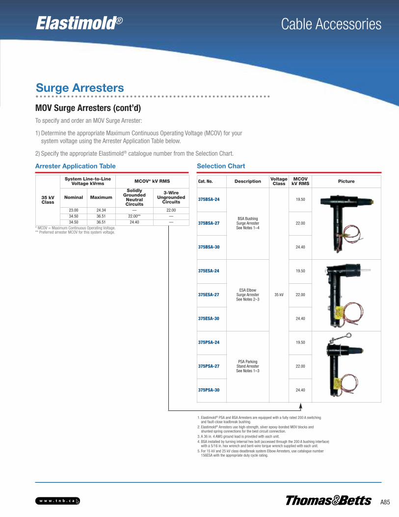
Elastimold® Cable Accessories
A85w w w . t n b . c a
To specify and order an MOV Surge Arrester:
1) Determine the appropriate Maximum Continuous Operating Voltage (MCOV) for your system voltage using the Arrester Application Table below.
2) Specify the appropriate Elastimold® catalogue number from the Selection Chart.
35 kVClass
System Line-to-LineVoltage kVrms MCOV* kV RMS
Nominal Maximum
SolidlyGrounded NeutralCircuits
3-Wire UngroundedCircuits
23.00 24.34 — 22.0034.50 36.51 22.00** —34.50 36.51 24.40 —
Arrester Application Table
Cat. No. Description VoltageClass
MCOVkV RMS Picture
375BSA-24
BSA Bushing Surge Arrester See Notes 1–4
35 kV
19.50
375BSA-27 22.00
375BSA-30 24.40
375ESA-24
ESA Elbow Surge Arrester See Notes 2–3
19.50
375ESA-27 22.00
375ESA-30 24.40
375PSA-24
PSA Parking Stand ArresterSee Notes 1–3
19.50
375PSA-27 22.00
375PSA-30 24.40
Selection Chart
1. Elastimold® PSA and BSA Arresters are equipped with a fully rated 200 A switching and fault-close loadbreak bushing.
2. Elastimold® Arresters use high-strength, silver epoxy-bonded MOV blocks and shunted spring connections for the best circuit connection.
3. A 36 in. 4 AWG ground lead is provided with each unit.4. BSA installed by turning internal hex bolt (accessed through the 200 A bushing interface)
with a 5/16 in. hex wrench and bent-wire torque wrench supplied with each unit.5. For 15 kV and 25 kV class deadbreak system Elbow Arresters, use catalogue number
156ESA with the appropriate duty cycle rating.
Surge Arresters
MOV Surge Arresters (cont’d)
* MCOV = Maximum Continuous Operating Voltage.** Preferred arrester MCOV for this system voltage.

Elastimold® Cable Accessories
A86 w w w . t n b . c a
Molded Vacuum Recloser
The Elastimold® Recloser, in either single-phase or threephaseconfigurations, is fully compatible with SEL® ControlsSmart, Light and Flexible
The Elastimold® Recloser is world-class, by design. It responds to every hardware requirementthat utilities want.
Smart – Our recloser is Smart Grid ready with three integral load-side voltage sensors and provision to addsource-side voltage sensors, if desired. It was designed to be fully compatible with the industry’s No. 1 name in controls, Schweitzer Engineering Laboratories.
Light – The three-phase Elastimold® Recloser weighs 33% less than existing typical units. The simplicity ofthe mechanism design, and the compactness of the encapsulated components, contribute to making theElastimold® Recloser easier to move and install.
Flexible – The Elastimold® Recloser is modular, so field upgrades and retrofits are easy and fast. The singlephase recloser has a pole rotation mounting bracket for easier installation.
Made with Your Needs in Mind – We designed the Elastimold® Recloser only after extensive talks withelectric utilities. Its features, from easier-to-see open/close indicators to the many robust extra features thatwe consider “standard”, are there because of you.
Side Silicone Terminal
Magnetic Actuator
Current Transformer
Vacuum Bottle
Pull Rod Assembly
Position Indicator
Load Side Voltage Sensor
Upper Cover
Lower Cover
Bottom Silicone Sheds
Solid Dielectric Diaphragm
Main Body EPDMInsulation
Top Silicone Sheds
Solid Dielectric Insulation
Lifting Rings
Highly-Visible360° Indicators
Current & VoltageSensors
Integrated PoleMounting Bracket
Manual Tripping Lever
Recloser Operation
The Elastimold® Molded Vacuum Recloser (MVR) operates electrically byenergizing a magnetic actuator system with a completely sealed housing. Each pole contains a vacuum interrupter sealed in solid dielectric insulation for mechanical and high dielectric strength.
An open-closed position indicator provides a 360-degree view. An external manual trip assembly is located on the side; when in the downposition, it maintains the recloser in a lockout position until it is manuallyrestored. All electrical control connections are made through a sealedsingle-environment control cable connector on the side.
The combination of the molded vacuum recloser with microprocessorcontrols accurately detects a wide range of line disturbances and provides reliable, high-speed isolation for adverse conditions.

Elastimold® Cable Accessories
A87w w w . t n b . c a
Molded Vacuum Recloser
Catalogue Numbering SystemIndicates field that must be filled in to complete order.
M V R
Interrupting Rating
12 25 kV
— Future
Phases
1 Single-Phase
3 Three-Phase Voltage Class
15 15.0 kV
27 27.0 kV
38 38.0 kVSource-Side Voltage Sensing
N No
1 One Voltage Sensor
3 Three Voltage Sensors
Cat. No. Description3188D0120G1 Three-phase Line Side Arrester Frame
3188D0121G1 Three-phase Load Side Arrester Frame
3188C0122G1 Single-phase Line Side Arrester Frame
3188C0123G1 Single-phase Load Side Arrester Frame
3070A1191P1 Wildlife Protector Top Bushing (one per phase)
3070A1190P1 Wildlife Protector Side Bushing (one per phase)
3188C0075G1 Source-side Voltage Sensors (one per phase)
3188D0119G1 Substation Mounting Frame
3188B0126G1 NEMA 2-hole pad
3180A0661P1 NEMA 4-hole pad
3070B0913G1 Aerial Lug
1548FH-ANC3JNAA Fisher Pierce® Overhead Faulted Circuit Indicator – Adaptive TripTM; 4 hr automatic reset time with current reset override (60 sec. after restoration of power), five ultra-bright LEDs for increase visibility display
1548FH-ANC3XNA1 Fisher Pierce® Overhead Faulted Circuit Indicator – Adaptive TripTM; 4 hr automatic reset time with current reset override (60 sec. after restoration of power), with 4 hr temporary fault reset time, temporary fault indication option, four red and one amber LED
Accessories
Control Model
1 SEL-351R, SEL-351R Falcon™ (14-pin)
2 SEL-651R (32-pin)
3 SEL-351RS Kestrel® (single-phase only)
S e q u e n t i a l N u m b e r s *
Sequential Numbers*
Control, Cable Length and Other Accessories
Ratings and Specifications
15 kV 27 kV 38 kV*
Nominal System Voltage (kV RMS) 14.4 25 35
Rated Maximum Voltage (kV RMS) 17.1 29.3 38
Nominal Frequency (Hz) 50 or 60 50 or 60 50 or 60
Phase Spacing on Three-Phase Units (Inches) 15.5 15.5 15.5
BIL (kV) 150 150 170
Power Frequency Withstand — Dry (kV) 50 50 70
Power Frequency Withstand — Wet (kV) 45 45 60
Continuous Current (A RMS) 800 800 800
Eight (8) Hour Overload Current (A RMS) 960 960 960
CT Ratio 1,000 to 1 1,000 to 1 1,000 to 1
15 kV 27 kV 38 kV*
Interrupting Current (kA RMS Symmetrical) 12.5 12.5 12.5
Making Current (kA Asymmetrical Peak) 32.5 32.5 32.5
Creepage Distances (Inches — Line to Ground) 41.5 41.5 41.5
Arc-Extinction Medium Vacuum Vacuum Vacuum
Insulation Medium EPDM/Silicon Rubber EPDM/Silicon Rubber EPDM/Silicon Rubber
Mechanical Operations 10,000 10,000 10,000
Operating Temperatures –40°C to 65°C –40°C to 65°C –40°C to 65°C
Voltage Sensor Accuracy (Load/Line) 3% / 1% 3% / 1% 3% / 1%
CT Accuracy Class 1 Class 1 Class 1
Weight (Single–Phase/Three-Phase) 57 lb. / 208 lb. 57 lb. / 208 lb. 58 lb. / 211 lb.
* Single phase 38 kV units are rated for use on grounded systems only. Three-phase 38 kV units can be used for single-phase tripping on grounded systems only.For ungrounded systems, three-phase tripping is required.
* Consult your T&B sales representative forcomplete catalogue number configuration.
SEL is a registered trademark of SchweitzerEngineering Laboratories, Inc.