access control sipass quick startup manual - … · building technologies fire safety &...
TRANSCRIPT

Building Technologies Fire Safety & Security Products
Access Control
SiPass® integrated
Quick Startup Manual

Liefermöglichkeiten und technische Änderungen vorbehalten. Data and design subject to change without notice. / Supply subject to availability. © 2010 Copyright by Siemens Building Technologies Fire & Security Products GmbH & Co. oHG
Wir behalten uns alle Rechte an diesem Dokument und an dem in ihm dargestellten Gegenstand vor. Der Empfänger erkennt diese Rechte an und wird dieses Dokument nicht ohne unsere vorgängige schriftliche Ermächtigung ganz oder teilweise Dritten zugänglich machen oder außerhalb des Zweckes verwenden, zu dem es ihm übergeben worden ist.
We reserve all rights in this document and in the subject thereof. By acceptance of the document the recipient acknowledges these rights and undertakes not to publish the document nor the subject thereof in full or in part, nor to make them available to any third party without our prior express written authorization, nor to use it for any purpose other than for which it was delivered to him.

3
Siemens Building Technologies
Fire Safety & Security Products 11.2009
Contents
1 Introduction .............................................................................................7 1.1 Quick Start-up Overview ...........................................................................7 1.2 Equipment Checklist .................................................................................8 1.2.1 SiPass integrated Installation License ......................................................8 1.2.2 SiPass integrated DVD .............................................................................8 1.2.3 Windows Network .....................................................................................8 1.2.4 Computer Requirements...........................................................................9 1.2.5 Microsoft SQL Server..............................................................................10 1.2.6 ACC Controllers ......................................................................................10 1.2.7 Local SiPass integrated Devices ............................................................10
2 Hardware Preparation...........................................................................12 2.1 Powering ACCs and Devices..................................................................12 2.2 Configuring the ACC ...............................................................................12 2.3 Connecting Devices ................................................................................14
3 ACC and FLN Field Service Tool .........................................................15 3.1 Installation ...............................................................................................15 3.2 Downloading Firmware and Testing Devices .........................................15 3.3 Configuring the FLN Bus.........................................................................15 3.4 Detecting Devices on an FLN Bus ..........................................................16 3.5 Selecting an Image File to Download .....................................................16 3.6 Downloading an Image File to a Single Device ......................................17 3.7 Performing a Batch Download ................................................................17
4 Software Installation.............................................................................18 4.1 Microsoft SQL Server 2008 Installation ..................................................18 4.2 SiPass integrated Installation..................................................................19 4.3 To configure SiPass integrated server settings ......................................20 4.4 Installing SiPass integrated Remote Clients...........................................22
5 SiPass integrated Configuration .........................................................23 5.1 Operators and Operator Groups .............................................................23 5.1.1 Creating an Operator Group ...................................................................23 5.1.2 Creating an Operator ..............................................................................24 5.2 Time Schedules ......................................................................................25 5.2.1 Creating Time Schedules........................................................................25 5.3 Components............................................................................................25 5.3.1 Creating Units .........................................................................................25 5.3.2 Creating FLNs .........................................................................................26 5.3.3 Creating Devices.....................................................................................26 5.3.4 FLN Configuration ...................................................................................27 5.4 Access Privileges....................................................................................27 5.4.1 Creating Access Levels ..........................................................................27 5.4.2 Creating Access Groups .........................................................................28 5.5 Workgroups.............................................................................................28 5.5.1 Creating Workgroups ..............................................................................28 5.6 Credential Profiles...................................................................................29 5.6.1 Adding and Deleting Credential Profiles .................................................29 5.7 Cardholders.............................................................................................29 5.7.1 Creating Cardholders ..............................................................................29 5.8 Assigning Access Privileges ...................................................................30 5.8.1 Assigning Access to a Cardholder ..........................................................30 5.8.2 Assigning Access to Cardholders from a Workgroup .............................31

4
Siemens Building Technologies
Fire Safety & Security Products 11.2009
6 Keyword index.......................................................................................33

5
Siemens Building Technologies
Fire Safety & Security Products 11.2009


7
Siemens Building Technologies
Fire Safety & Security Products 11.2009
1 Introduction
Congratulations on choosing the SiPass® integrated access control and security solution. This manual provides a brief overview to quickly setting up and configur-ing the SiPass integrated system for operation.
SiPass integrated is a feature rich application designed for mid to high-end building environments. This manual does not explain each and every parameter provided by the system. Instead this manual explains how to get the most out of your new system (both hardware and software) in as short amount of time as possible. In fact, it is anticipated that you can configure and begin operating a SiPass inte-grated system with up to 20 doors, and 100 cardholders within 8 hours, using this guide as a reference tool. Of course, the location of doors and the accessibility of wiring these doors may be responsible for extending the time required.
Before you begin, it is assumed that your knowledge of PCs (including the latest Windows Operating System) and networking of these PCs is at an intermediate level or higher. After all, SiPass integrated is a fully networked solution that does require the configuration of IP addresses for both its hardware and software com-ponents.
1.1 Quick Start-up Overview
The following list provides an overview of each step you must take in order to get your SiPass integrated system up and running from the ground up:
1. Gather all the items in the equipment checklist.
2. Set up an ACC.
3. Connect devices to the ACC.
4. Install SQL Server on the SiPass integrated Server PC.
5. Install SiPass integrated Server and Client.
6. Configure DCOM security and firewalls.
7. Install SiPass integrated remote clients.
8. Create an operator and operator group in SiPass integrated.
9. Create Time schedules.
10. Create your hardware components in SiPass integrated.
11. Create access levels and access groups.
12. Create Workgroups.
13. Create Cardholders.
14. Assign access to cardholders.

8
Siemens Building Technologies
Fire Safety & Security Products 11.2009
1.2 Equipment Checklist
Listed below is the basic equipment required for a successful installation of SiPass integrated.
� SiPass integrated installation license
� SiPass integrated Software DVD
� PC (compatible with the latest Windows Operating System) that meets the Si-Pass integrated Server requirements
� Microsoft SQL Server on CD (if not already installed)
� ACC Controller
� Windows Network
� Local SiPass integrated Devices (Reader Interfaces / Input Modules etc).
Field Level Network Devices can be installed using the ACC and FLN Field Ser-vice Tool. For further information on how to use this tool, please refer Section 5 of this Quick Start Manual.
� Input Devices (e.g. PIR, Exit Switch, duress button)
� Output Devices (e.g. Horn, siren, strobe light)
� Compatible readers (e.g. Wiegand output)
� Door Locks
� Peripheral devices and drivers if required (e.g. card printer)
1.2.1 SiPass integrated Installation License
When you purchase your SiPass integrated software package, you will be provided with a license that activates the appropriate features in your software. This license is required for the installation of the system on a PC and includes the name of the site at which the installation will take place.
If this installation is for demonstration purposes, you can enter a serial number of DEMO (case sensitive) during the install process to unlock a demonstration li-cense.
1.2.2 SiPass integrated DVD
When ordering your SiPass integrated system, you can also order a SiPass inte-grated DVD. This contains the program files required for installation along with other tools that may be necessary to assist you when installing the system.
1.2.3 Windows Network
The SiPass integrated Server, SiPass integrated Client Workstation and the ACC all communicate using TCP/IP. Therefore, they must all be configured on the same network. Since SiPass integrated supports the Windows operating environment, this must be a Windows network. This can either be a Windows domain or a work-group type network environment.
9
Siemens Building Technologies
Fire Safety & Security Products 11.2009
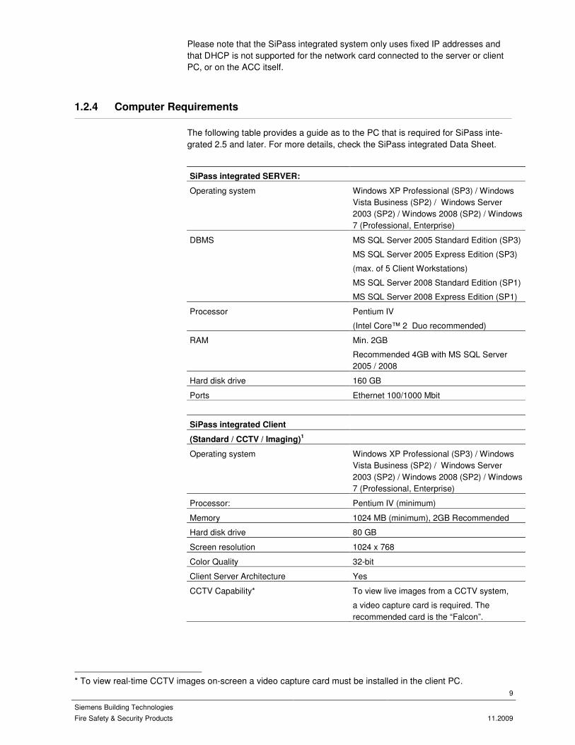
Please note that the SiPass integrated system only uses fixed IP addresses and that DHCP is not supported for the network card connected to the server or client PC, or on the ACC itself.
1.2.4 Computer Requirements
The following table provides a guide as to the PC that is required for SiPass inte-grated 2.5 and later. For more details, check the SiPass integrated Data Sheet.
SiPass integrated SERVER:
Operating system Windows XP Professional (SP3) / Windows Vista Business (SP2) / Windows Server 2003 (SP2) / Windows 2008 (SP2) / Windows 7 (Professional, Enterprise)
DBMS MS SQL Server 2005 Standard Edition (SP3)
MS SQL Server 2005 Express Edition (SP3)
(max. of 5 Client Workstations)
MS SQL Server 2008 Standard Edition (SP1)
MS SQL Server 2008 Express Edition (SP1)
Processor Pentium IV
(Intel Core™ 2 Duo recommended) RAM Min. 2GB
Recommended 4GB with MS SQL Server 2005 / 2008
Hard disk drive 160 GB
Ports Ethernet 100/1000 Mbit
SiPass integrated Client
(Standard / CCTV / Imaging)1
Operating system Windows XP Professional (SP3) / Windows Vista Business (SP2) / Windows Server 2003 (SP2) / Windows 2008 (SP2) / Windows 7 (Professional, Enterprise)
Processor: Pentium IV (minimum)
Memory 1024 MB (minimum), 2GB Recommended Hard disk drive 80 GB
Screen resolution 1024 x 768
Color Quality 32-bit
Client Server Architecture Yes
CCTV Capability* To view live images from a CCTV system,
a video capture card is required. The recommended card is the “Falcon”.
* To view real-time CCTV images on-screen a video capture card must be installed in the client PC.

10
Siemens Building Technologies
Fire Safety & Security Products 11.2009
1.2.5 Microsoft SQL Server
SiPass integrated requires Microsoft SQL Server for its database management. Please ensure you have a supported version available on CD or installed on your Server PC.
SQL 2008 SP1 SQL 2008 Ex-
press SP1 SQL 2005 (SP3 or later)
SQL 2005 Ex-press
SiPass
Integrated 2.50
Yes
Yes
Yes Yes
Please note:
There are limitations on SQL Express. Please refer to the SiPass integrated Instal-lation Manual for more details.
1.2.6 ACC Controllers
Advanced Central Controllers (ACCs) are at the heart of the SiPass integrated ac-cess control and security system. The ACC makes most decisions within the ac-cess control system and reports all activity to the SiPass integrated server.
The ACC is an IP based device and therefore sits on the same network as the software and communicates with the server using TCP/IP.
Please note that the correct version of firmware required to operate the ACC comes on the SiPass integrated software DVD. However, it would be prudent to check with your local field support representative to see if an updated firmware version for the ACC is available.
1.2.7 Local SiPass integrated Devices
SiPass integrated supports a number of local devices. These devices are used to connect the physical components such as card readers, door locks, etc., to the system. Each device connects to an ACC, which provides six communications channels (called FLNs) for use with devices.
The following table provides a list of devices that can be connected to an ACC:
Device Description
SRI (ADS52x0) Single Reader Interface (ACC Protocol)
DRI (ADD51x0) Dual Reader Interface (ACC Protocol)
ERI (ADE5300) Eight Reader Interface (ACC Protocol)
IPM (AFI5100) Input Module (ACC Protocol)
OPM (AF05100) Output Module (ACC Protocol)
8IO (AF05200) Eight Input / Output Module (ACC Protocol)
DC12 Dual Reader Interface (ENTRO protocol)
DC22 Dual Reader Interface (ENTRO protocol)
DC800 Dual Reader Interface (ENTRO protocol)
PD30/PD40 Single Reader + Door Lock (ENTRO protocol)

11
Siemens Building Technologies
Fire Safety & Security Products 11.2009
Device Description
IOR6 Input/Output Module (ENTRO protocol)
ATI5100 Intrusion Arming Terminal

12
Siemens Building Technologies
Fire Safety & Security Products 11.2009
2 Hardware Preparation
The first step in installing your SiPass integrated system is to configure your hard-ware. The Advanced Central Controller (ACC) is at the core of the system. This chapter explains how to set up the ACC and supported devices.
The following steps will need to be done to get an ACC with devices up and run-ning:
� Connect power to the ACC and devices
� Connect to the ACC via HyperTerminal or Telnet
� Set the Unit name, IP address and host IP Address
� Download ACC Firmware
� Connect devices to the ACC via the FLNs
2.1 Powering ACCs and Devices
The power needs of the ACC and FLN Devices is as follows:
� The ACC requires a 24V DC supply with 500mA to run. The cable length be-tween the power source and the ACC should not exceed 3m.
� FLN Devices require 24V or 12V.
Please refer the relevant hardware manuals for more details.
To power the ACC and its devices, simply connect the positive, negative and earth wires from the supply with the matching terminal on the board.
2.2 Configuring the ACC
Before using an ACC with SiPass integrated, it is important to change the factory default values to match your network and download appropriate firmware. More de-tails on these procedures are available in the ACC Hardware manual.
There are two ways to initially configure an ACC:
� Connect a diagnostic cable from a COM port on a PC to the DIAG port on the ACC.
� Connect to the ACC with Telnet. (this may require some modifications to the network settings on your PC)
To configure an ACC:
1. Create a connection to the ACC:
– With HyperTerminal using a baud rate of 9600.
– With Telnet: the ACC has an IP of 192.168.1.250 and a subnet mask of 255.255.255.0
13
Siemens Building Technologies
Fire Safety & Security Products 11.2009
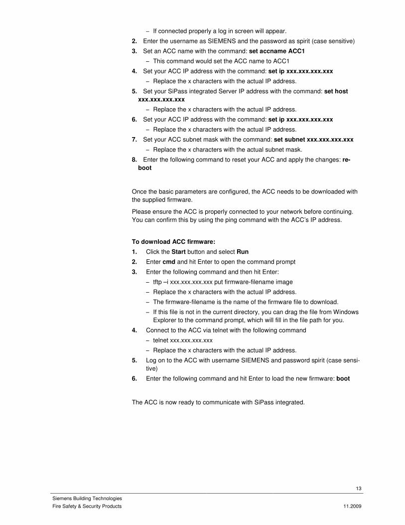
– If connected properly a log in screen will appear.
2. Enter the username as SIEMENS and the password as spirit (case sensitive)
3. Set an ACC name with the command: set accname ACC1
– This command would set the ACC name to ACC1
4. Set your ACC IP address with the command: set ip xxx.xxx.xxx.xxx
– Replace the x characters with the actual IP address.
5. Set your SiPass integrated Server IP address with the command: set host
xxx.xxx.xxx.xxx
– Replace the x characters with the actual IP address.
6. Set your ACC IP address with the command: set ip xxx.xxx.xxx.xxx
– Replace the x characters with the actual IP address.
7. Set your ACC subnet mask with the command: set subnet xxx.xxx.xxx.xxx
– Replace the x characters with the actual subnet mask.
8. Enter the following command to reset your ACC and apply the changes: re-
boot
Once the basic parameters are configured, the ACC needs to be downloaded with the supplied firmware.
Please ensure the ACC is properly connected to your network before continuing. You can confirm this by using the ping command with the ACC’s IP address.
To download ACC firmware:
1. Click the Start button and select Run
2. Enter cmd and hit Enter to open the command prompt
3. Enter the following command and then hit Enter:
– tftp –i xxx.xxx.xxx.xxx put firmware-filename image
– Replace the x characters with the actual IP address.
– The firmware-filename is the name of the firmware file to download.
– If this file is not in the current directory, you can drag the file from Windows Explorer to the command prompt, which will fill in the file path for you.
4. Connect to the ACC via telnet with the following command
– telnet xxx.xxx.xxx.xxx
– Replace the x characters with the actual IP address.
5. Log on to the ACC with username SIEMENS and password spirit (case sensi-tive)
6. Enter the following command and hit Enter to load the new firmware: boot
The ACC is now ready to communicate with SiPass integrated.

14
Siemens Building Technologies
Fire Safety & Security Products 11.2009
2.3 Connecting Devices
Devices connect to the ACC via the 6 FLNs, which all use the RS-485 protocol.
The maximum recommended load rating for an FLN is 16. This number is calcu-lated by adding up the load rating for each attached device. For example, an SRI has a load rating of 1 and a DRI has a rating of 2. Therefore, you could have up to 16 SRIs or 8 DRIs on a single FLN without any problems.
It is recommended that these devices are connected using a daisy-chain wiring configuration, with splices in the comms cable made at or near each local device. The maximum wiring distance for any FLN channel is approximately 1000m (3280.84 ‘). If the wiring run must extend beyond this distance, an RS-485 signal booster will be required to ensure that the quality of the communications signal is maintained.
To connect local devices to an FLN channel of the ACC:
1. Connect the active (positive) wire of the FLN bus line to the + connection of an FLN port - terminal connector.
2. Connect the neutral (negative) wire of the FLN bus line to the - connection of the same FLN port - terminal connector.
3. Connect the cable shield to the S connection of the same FLN port - terminal connector.
4. Connect each required local device to the FLN bus line, ensuring that the connection is made in a Daisy Chain orientation. Refer to each local device User’s Guide for more information about wiring these devices to the FLN channel.

15
Siemens Building Technologies
Fire Safety & Security Products 11.2009
3 ACC and FLN Field Service Tool
The FLN Field Service Tool has been designed to assist in the installation of Field Level Network devices for use with the SiPass integrated Access Control and Se-curity System. This includes:
� Dual Reader Interfaces (DRI)
� Single Reader Interfaces (SRI)
� Eight Reader Interface (ERI)
� Output Point Modules (OPM)
� Input Point Modules (IPM)
� Intrusion Arming Terminal (IAT-010)
3.1 Installation
Installation can be performed by launching the FLN Field Service Tool’s Setup.exe file. This action will install the Visual C++ 2005 redistributable package automati-cally. On machines that do not have the .NET Framework 2.0, it should install the .NET 2.0 automatically.
3.2 Downloading Firmware and Testing Devices
Devices must be connected to a COM Port on a PC running the Field Service Tool via a RS232 – RS485 Bus converter.
The process to download firmware and test devices is as follows:
1. Configure the FLN Bus.
2. Select an image file for download.
3. Detect all devices on the FLN Bus.
4. Download firmware to a device.
5. Configure the device.
3.3 Configuring the FLN Bus
The process of configuring the FLN Bus is as follows:
1. Open the ACC and FLN Field Service Tool dialog.
2. Select FLN Bus on the left hand tree menu of the dialog. The FLN Bus infor-mation will be displayed on the adjacent panel on the right.

16
Siemens Building Technologies
Fire Safety & Security Products 11.2009
3. From the Communication Port drop down menu, select the COM port on the PC to which the FLN bus is connected.
4. Select the Settings button from the toolbar of this dialog.
5. Select the Advanced tab.
6. Tick the following checkboxes that apply:
– NT Series RIMs
– This option must be selected if you have NT Series RIM devices connected to the FLN bus. Otherwise, they will not be detected.
– Check IDs above 64
– Select this option if any unit IDs for connected devices are greater than 64. Most devices will have an ID less than 64.
– Upgrade Only if Image Newer
– If this option is selected during global downloads, the FLN tool will not download firmware to any device with a version equal, or newer than the selected version.
7. Click Apply.
8. Click OK.
3.4 Detecting Devices on an FLN Bus
1. Ensure that the FLN bus has been configured.
2. Select the Search button.
The field service tool will detect all the RIM devices connected to the FLN bus. Any units found will be displayed in the tree view under the FLN bus.
3.5 Selecting an Image File to Download
The process for selecting an image file to download is as follows:
1. Ensure that the FLN bus has been configured, and all the connected devices have been detected.
2. Select the Settings button. The Settings dialog will appear. The Global tab will be open by default.
3. Select the tab corresponding to the device you want to select a firmware im-age file for.
4. Select the Browse button. Use the Open dialog to search for the firmware image file you want to download.
5. Select Open.
6. Select OK.
7. Repeat steps 3-6 for each device type that you will be configuring for the FLN tool.
8. Click Apply.
17
Siemens Building Technologies
Fire Safety & Security Products 11.2009
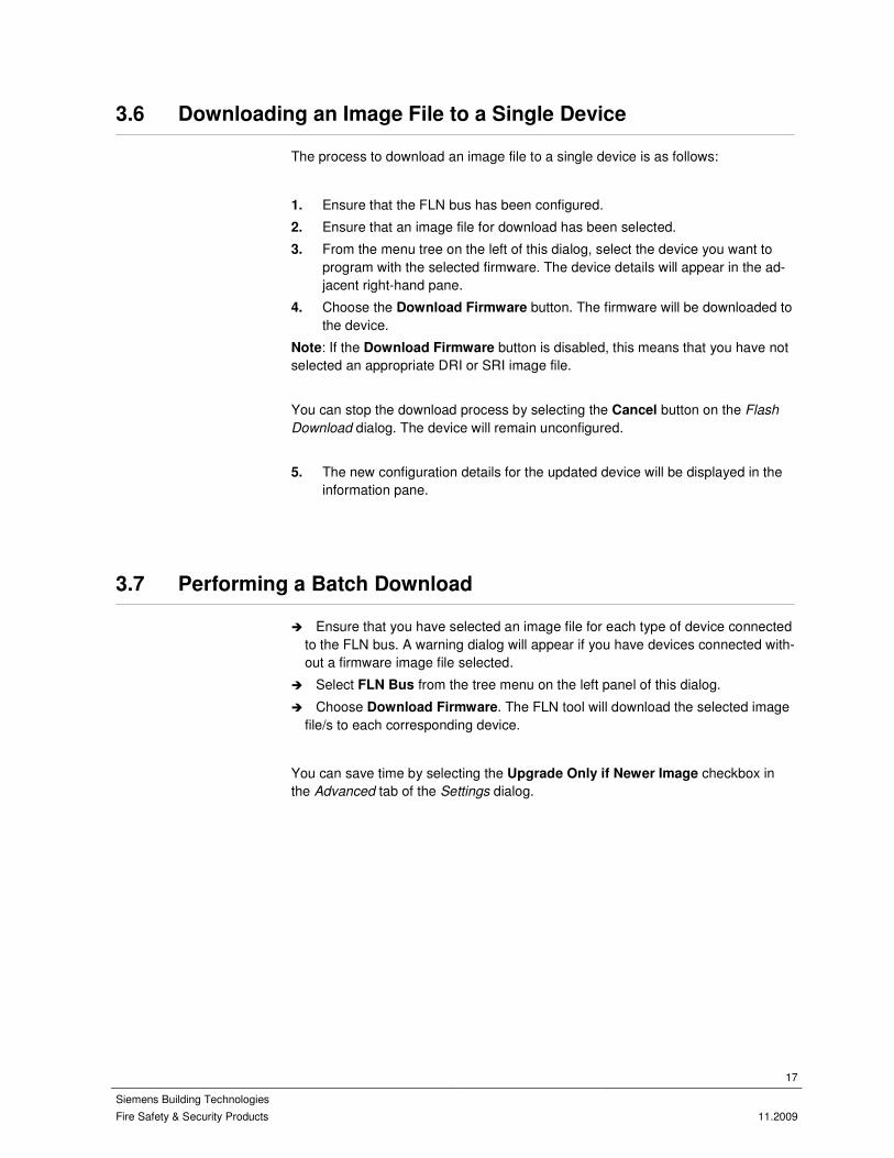
3.6 Downloading an Image File to a Single Device
The process to download an image file to a single device is as follows:
1. Ensure that the FLN bus has been configured.
2. Ensure that an image file for download has been selected.
3. From the menu tree on the left of this dialog, select the device you want to program with the selected firmware. The device details will appear in the ad-jacent right-hand pane.
4. Choose the Download Firmware button. The firmware will be downloaded to the device.
Note: If the Download Firmware button is disabled, this means that you have not selected an appropriate DRI or SRI image file.
You can stop the download process by selecting the Cancel button on the Flash
Download dialog. The device will remain unconfigured.
5. The new configuration details for the updated device will be displayed in the information pane.
3.7 Performing a Batch Download
� Ensure that you have selected an image file for each type of device connected to the FLN bus. A warning dialog will appear if you have devices connected with-out a firmware image file selected.
� Select FLN Bus from the tree menu on the left panel of this dialog.
� Choose Download Firmware. The FLN tool will download the selected image file/s to each corresponding device.
You can save time by selecting the Upgrade Only if Newer Image checkbox in the Advanced tab of the Settings dialog.

18
Siemens Building Technologies
Fire Safety & Security Products 11.2009
4 Software Installation
The next step involves installing the SiPass integrated software and pre-requisites.
The installation should occur in this order:
� Install Microsoft SQL Server
� Install SiPass integrated Server and Client
� Configure firewalls and DCOM security
� Install SiPass integrated remote clients (Please refer to the SiPass integrated Installation Manual)
4.1 Microsoft SQL Server 2008 Installation
This section briefly explains how to install Microsoft SQL Server 2008.
Microsoft SQL Server 2008 is the newest Microsoft SQL Server version. It has nu-merous new features that improve server management and application downtime.
To install SQL Server 2008:
1. Run the Microsoft SQL Server 2008 Setup from the CD.
2. The SQL Server Installation Centre dialog will be displayed. On the left panel, click Installation.
3. Next, select New SQL Server stand-alone installation or add features to an existing installation from the right panel of the dialog.
4. The SQL Server 2008 Setup dialog is displayed next. This dialog displays the Setup Support Rules that identifies problems that might occur when SQL Server Setup support files are installed. When the operation is complete, click OK.
5. In the next dialog, select the Enter the product key: option.
6. Enter a product key in the field provided in this dialog. Click Next.
7. The next dialog displays the License Terms. Read this and tick the I accept
the license terms and click Next. A dialog to Setup Support Files will be dis-played.
8. Click Install to continue. The prerequisites for SQL 2008 will be installed.
9. Click Next to continue the setup after the prerequisites are installed. The Fea-ture Selection dialog will appear next.
10. Select the features you wish to install:
– We recommend clicking Database Engine Services, Client Tools Con-nectivity and Management Tools - Basic.
– To select a different installation path click the ... button of the Shared feature directory: field to select a path for each component that you are installing.
11. Click Next to navigate to the Instance Configuration dialog.
12. Select the Default instance option.
13. Click Next if you pass the System Configuration Check.
– The IIS Feature Requirement is not needed for SiPass integrated.
19
Siemens Building Technologies
Fire Safety & Security Products 11.2009
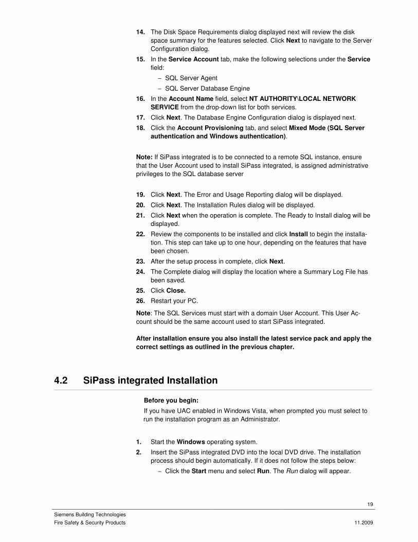
14. The Disk Space Requirements dialog displayed next will review the disk space summary for the features selected. Click Next to navigate to the Server Configuration dialog.
15. In the Service Account tab, make the following selections under the Service
field:
– SQL Server Agent
– SQL Server Database Engine
16. In the Account Name field, select NT AUTHORITY\LOCAL NETWORK
SERVICE from the drop-down list for both services.
17. Click Next. The Database Engine Configuration dialog is displayed next.
18. Click the Account Provisioning tab, and select Mixed Mode (SQL Server
authentication and Windows authentication).
Note: If SiPass integrated is to be connected to a remote SQL instance, ensure that the User Account used to install SiPass integrated, is assigned administrative privileges to the SQL database server
19. Click Next. The Error and Usage Reporting dialog will be displayed.
20. Click Next. The Installation Rules dialog will be displayed.
21. Click Next when the operation is complete. The Ready to Install dialog will be displayed.
22. Review the components to be installed and click Install to begin the installa-tion. This step can take up to one hour, depending on the features that have been chosen.
23. After the setup process in complete, click Next.
24. The Complete dialog will display the location where a Summary Log File has been saved.
25. Click Close.
26. Restart your PC.
Note: The SQL Services must start with a domain User Account. This User Ac-count should be the same account used to start SiPass integrated.
After installation ensure you also install the latest service pack and apply the
correct settings as outlined in the previous chapter.
4.2 SiPass integrated Installation
Before you begin:
If you have UAC enabled in Windows Vista, when prompted you must select to run the installation program as an Administrator.
1. Start the Windows operating system.
2. Insert the SiPass integrated DVD into the local DVD drive. The installation process should begin automatically. If it does not follow the steps below:
– Click the Start menu and select Run. The Run dialog will appear.

20
Siemens Building Technologies
Fire Safety & Security Products 11.2009
– Type d:\Setup.exe to start the install procedure, where “d” indicates the drive letter for you DVD ROM drive. Click the OK button to start the in-staller
3. The SiPass integrated Installation screen will appear. The pre-installation pro-gram allows you to perform tasks such as reading the Release Notes. Follow the instructions and proceed to the SiPass integrated install. The Welcome to
SiPass dialog will appear.
4. Click Next >. The SiPass integrated License Agreement dialog will appear.
5. Select the ‘I accept the license agreement’ option to enable the Next but-ton, once you have read and understood the terms of the end user license agreement.
6. Click Next. The Hardware Type dialog will appear.
7. Select the SiPass integrated platform that you wish to install by checking the option that corresponds to your license.
8. Click the Next > button. The License Options dialog will appear.
9. Complete the fields in the License Options dialog, according to the details that appear on your Validity Check form issued with your License Key.
10. Click Next. A new License Options dialog will appear.
11. Enter the details into each field according to your license.
12. Click Next. The Select Installation Type dialog will appear.
13. Select the type of installation you want (Custom / Typical / Complete).
– The Select Features dialog will appear if you have chosen the Custom installation. If you have chosen a Typical or Complete installation, pro-ceed to step 19.
14. Select which features are to be installed by clicking on the hard drive icon for a particular feature and selecting “Will be installed on the local hard drive”
from the drop down menu.
15. Specify the destination for the SiPass software by choosing Browse.
16. Click Next. You will be asked to supply a name for each CCTV Bus that you are installing.
– The Bus Name dialog will appear for each type of CCTV Bus you are in-stalling. If you purchased multiple buss licenses of the same type, enter the names on a separate line by pressing CTRL + Enter for a carriage return.
17. Enter a suitable password into the Password field, and re-enter the same password into the Confirm Password field.
18. Click Next. You will be prompted to confirm that you want to continue the in-stallation “Ready to Install Application”.
19. Click Next >. The installation will proceed and the installation progress indica-tor will appear. When completed, the Setup Complete dialog will appear.
20. Click Finish.
4.3 To configure SiPass integrated server settings
Before you begin:
Ensure that you have already created your SiPass integrated Group in Windows, which contains the Windows user accounts that will be running SiPass integrated.

21
Siemens Building Technologies
Fire Safety & Security Products 11.2009
1. If you are running Windows Vista, click the Start button, enter comexp.msc into the search bar and hit the Enter key. Proceed to step 5.
2. If you are running Windows XP or Windows 2003 Server, click the Windows Start menu and select Settings > Control Panel. The Control Panel window will appear.
3. Double click Administrative Tools.
4. Double click Components Services.
5. Double click the Component Services icon.
6. Double click Computers.
7. Right click on the My Computer icon and choose Properties.
8. Select the COM Security tab.
9. Click the Edit Limits button for Access Permissions.
10. Click Add.
11. Enter your SiPass Group and click OK.
12. Tick Remote Access for your SiPass Group.
13. Click OK.
14. Click the Edit Limits button for the Launch and Activation Permissions.
15. Click Add.
16. Enter your SiPass Group and click OK.
17. Tick Remote Activation for your SiPass Group.
18. Click OK.
19. Double click the My Computer icon.
20. Double click DCOM Config.
21. Right click on the advaNTage Server icon and select Properties.
22. Select the Security tab.
23. Select Customize from the Launch and Activation Permissions section and click Edit.
24. Click Add.
25. Enter your SiPass Group and click OK.
26. Tick Remote Activation for your SiPass Group.
27. Click OK.
28. Select Customize from the Access Permissions section and click Edit.
29. Click Add.
30. Enter your SiPass Group and click OK.
31. Tick Remote Access for your SiPass Group.
32. Click OK.
33. Click OK again.
34. Close the open dialogs.
35. Ensure that the Windows Firewall has been disabled.
NOTE
The Local Security Policy setting for ‘Network Access: Sharing and security model for local accounts’ must be set to Classic. The DCOM Configuration folder can be found in the Tools folder, which is available on the Installation CD.
You will need to restart your SiPass integrated Server before these changes take effect.

22
Siemens Building Technologies
Fire Safety & Security Products 11.2009
4.4 Installing SiPass integrated Remote Clients
To install a SiPass integrated Client:
1. Follow the procedure To Perform a SiPass integrated Installation, to step 8.
2. Fill in the License Options dialog with the same details as the original installa-tion.
– Click Next to continue.
3. Complete the second License Options dialog with the same details as the original installation.
– Click Next to continue.
4. Select Custom and click Next to continue to the Select Features dialog.
5. Select only the Client option(s) you are installing.
– For more details please refer to the Installation Manual
6. Ensure other items in the dialog are marked with a red cross, described as “Entire feature will be unavailable”.
Stop!
Ensure that the SiPass integrated Server option is marked as described above, so that the server will NOT be installed.
7. Click Next. The SiPass Server dialog will appear, if you are installing the Cli-ent on a PC other than the SiPass integrated Server PC.
8. Enter the name of the PC where the SiPass integrated Server has been in-stalled into the Type Server Computer Name field.
9. Click Next. The Ready to Install dialog will appear.
10. Click Next. The SiPass integrated Client installation will proceed and the pro-gress indicator will appear. After completion, the Setup Complete dialog will appear.
11. Click Finish. The new SiPass integrated client has now been installed.

23
Siemens Building Technologies
Fire Safety & Security Products 11.2009
5 SiPass integrated Configuration
This section involves configuring your SiPass integrated system. It covers the fol-lowing areas:
� Creating operators and operator groups
� Creating time schedules
� Creating your hardware components
� Creating access levels and groups
� Creating workgroups
� Creating cardholders
� Assigning access groups to cardholders
5.1 Operators and Operator Groups
Operators are responsible for maintaining the system Database, and monitoring the site. They must have access to system information, but there may be occa-sions where you wish to impose limits on what an operator can change.
5.1.1 Creating an Operator Group
To create an Operator Group:
1. Select Operator Group from the Program toolbar to display the Operator
Group dialog.
2. Complete the fields in the General section under Navigation.
– If some operator group options are changed, any operator who belongs to that group and is currently using a Client must log off and then log back on before the changes will take effect.
3. Select Cardholder Fields to assign some or all of the cardholder fields to this operator group. For example you might not want one operator group to be able to view cardholder PINs.
– Once a field is selected you can double click it to change the privilege from [v] (View) to [e] (Edit)
4. Select System Functions to assign some or all of the system functions to this operator group. For example you need to add the Cardholders System Func-tion if you want this operator group to modify cardholder records.
– Select a function and click Add to add just the one, or click Add All to add them all at the same time
5. Select the level of privilege, by double-clicking on the system function, to change the privilege level.
– c (Create). Allows members of the group to create, delete and view Database records.
– v (View).
Allows members of the operator group to view the records only.

24
Siemens Building Technologies
Fire Safety & Security Products 11.2009
– e (Edit).
Allows members of the group to view and modify existing Database re-cords.
6. Select Audit Trail Reports if your operator group has access to reporting functions.
– Select the Audit Trail Reports over which the operator has control.
7. Select Device Group to assign device groups to your operator group. These are like a point group but for devices. The operator group requires access to a device via a Device Group to view and modify the device.
8. Select FLN Group to assign FLN groups to your operator group. These are like a point group but for FLNs. The operator group requires access to an FLN via a FLN Group to view and modify it.
9. Select Holidays to assign your system defined Holidays to an operator group. Operators can only view and modify holidays that they have privileges to.
10. Select Site Plan to assign site plans to your operator group. This defines which site plans they can view and modify.
11. Select Point Groups to assign point groups to your operator group. Please note this will affect the points an operator can see.
12. Select SiPass Explorer Items to assign appropriate privileges for individual SiPass Explorer items to your operator group.
13. Select Time Period to assign specific time periods to your operator group.
14. Select Unit Group to assign Unit groups to your operator group. These are like a point group but for Units. The operator group requires access to a Unit via a Unit Group to view and modify it.
15. Select Work Groups to assign Work Groups to your operator group.
16. Select the work groups over which the operator has control. Please note that only those cardholders that belong to the assigned work groups can be ad-ministered by the Operator. Any audit trail entries (including reports) relating to cardholders that do not belong to these assigned work groups will not ap-pear when the Operator is logged on.
– If no workgroups are assigned to an operator group, that operator group will be unable to create cardholder records. Also, no card accesses will be visible to that operator from the Audit Trail.
17. Select Component Group to assign Component Groups to your operator group.
18. Click Save to complete creating the operator group.
5.1.2 Creating an Operator
Adding an operator to the system:
1. Select Operator from the Program menu.
2. Complete the operator’s identification details.
– Complete the automatic logon details if required.
3. Complete the operator’s access details.
4. Click Save to save the operator’s record.

25
Siemens Building Technologies
Fire Safety & Security Products 11.2009
5.2 Time Schedules
Time Schedules define when certain events should occur at your site. For exam-ple, cardholders can be denied access after business hours by creating a Time Schedule that gives them access during office hours only.
5.2.1 Creating Time Schedules
To create a Time Schedule:
1. Select Time Schedule from the Program menu. The Time Schedule dialog will appear.
2. Enter a unique name identifying the Time Schedule in the Time Schedule
field.
– You can enter up to 40 characters, in any combination of upper and lower case letters, and numbers.
3. Define the time intervals that will make up the Time Schedule.
– Select a Day Type first then enter appropriate Start and Stop times
– Click Add to add the time interval to the Defined Time Intervals list.
4. Click Save. The Time Schedule will be saved in the system.
5.3 Components
The SiPass integrated system monitors and reports vital information regarding events that occur at your site. Before SiPass integrated can do this, the system must be programmed with details about the layout and the hardware structure of the site.
5.3.1 Creating Units
To create an ACC:
5. Select Components from the System menu. The Components dialog will ap-pear.
6. Select the Server in the left hand pane.
7. Select the ACC Controllers communications channel.
8. Click the New Unit button. A new ACC will appear connected to the comms channel and a new tab will be available.
9. Enter the name of the ACC unit into the Unit Name field. This name must ex-actly match the name used when configuring your ACC.
10. Select the correct time zone for your ACC’s region from the Time Zone drop-down box.
11. Select the alarm definition that will apply to this ACC from the Alarm Defini-
tion drop-down box.
12. Select a Backup mode for ACC database.

26
Siemens Building Technologies
Fire Safety & Security Products 11.2009
13. Enter the serial number of the ACC into the Serial Number field.
– The serial number will have been issued with the ACC unit (should be printed on the sticker on the ACC).
– The Unit No. will be automatically assigned.
14. Select the appropriate operation options, as described in the User Manual.
– These options do not need to be modified for most installations.
15. Click the Save button. The ACC details will be saved in the system.
5.3.2 Creating FLNs
To create an FLN:
1. Select Components from the System menu. The Components dialog will ap-pear.
2. Select the Server in the left hand pane.
3. Select the ACC Controllers communications channel.
4. Select the ACC to which you want to configure an FLN connection.
5. Click the New FLN button. A new FLN will appear connected to the unit and a new tab will be available.
6. Enter a name for the FLN into the Name field.
7. Select the number of the FLN Connection from the Number drop-down box.
8. Select which kind of FLN you wish to add from the Type drop down box.
9. Click the Save button. The details for the FLN connection will be saved in the system.
5.3.3 Creating Devices
To create a Device:
1. Select Components from the System menu. The Components dialog will ap-pear.
2. Select the Server in the left hand pane.
3. Select the ACC Controllers communications channel.
4. Select the ACC to which you want to add a new device.
5. Select the FLN to which the Device will be connected.
6. Click the New Device button. A menu will appear showing a list of device types.
7. Select the device type you want to add. A series of tabs will become available according to the device selected.
8. Enter a meaningful name for the device into the Name field.
9. Select the alarm definition that will apply to this device from the Alarm Defini-
tion drop-down box.
– A default device number will automatically be assigned in the Device Number field. You can change this by entering a new number into the field.
10. Tick the Second Reader checkbox, if you want to enable both card readers on a DRI (DRI devices only).
27
Siemens Building Technologies
Fire Safety & Security Products 11.2009
– Select the Door Set configuration for the reader.
11. Click the Save button. The device details will be saved in the system.
5.3.4 FLN Configuration
An alternative way to add devices and FLNs to the system is to discover them with the FLN Configuration dialog. This dialog also allows you to download new firm-ware to FLN devices and modify their configuration.
More details are available in the User Manual:
To discover devices:
1. Select FLN Configuration from the System menu.
2. Expand the tree on the left hand side of the dialog by clicking the plus symbol until your ACC is visible.
3. Right click your ACC and select Search Range. The system will discover any unsaved devices that are communicating to the ACC, and highlight them in blue.
4. Select a discovered device, click Save New Device and click Yes to confirm the save.
– Before saving you can also change the device name and other attributes.
5. Repeat step 4 for all discovered devices.
6. Click Close to close the dialog.
5.4 Access Privileges
The level of access a cardholder has to various points at your site is determined by the access control privileges that they have been assigned. Cardholder access control is achieved by:
� Creating time schedules � Creating access levels
� Creating access groups
� Assigning access groups to cardholders and workgroups
5.4.1 Creating Access Levels
To create Access Levels:
1. Select Access Level from the Program menu. The Access Level dialog will appear.
2. Enter a name for the Access Level into the Name field.

28
Siemens Building Technologies
Fire Safety & Security Products 11.2009
3. Select the Time Schedule, for which the selected resources will be available, from the Time Schedule drop down list.
– The Copy button can be used to create a new Access level based on one that already exists.
– The Time Schedule button allows you to modify the Time Schedules.
– The Point Group button allows you to modify the point groups.
4. Select the resource type you are adding from the Type drop down box.
5. Select the resource in the bottom list that you want to add to the Access Level and click Add to add it
6. Repeat for every resource that you want to add to the access level.
7. Click the Save button. The Access Level record will be saved in the system.
5.4.2 Creating Access Groups
To create Access Groups:
1. Select Access Group from the Program menu. The Access Group dialog will appear.
2. Enter a name for the Access Group into the Access Group Name field. A list of Access Levels will appear in the Available Access Levels list.
3. Select the access level you want in the Access Group and use the Add button to move them to the Selected Access Levels list.
4. Repeat for every access level you want to add to the group.
5. Click the Save button. The Access Group record will be saved in the system.
5.5 Workgroups
Work groups are logical groups to which selected cardholders belong. Generally, cardholders whose jobs are the same or similar will belong to the same work group.
5.5.1 Creating Workgroups
To create a Work Group:
1. Select Work Group from the Operation menu.
2. Complete the Work Group identification details.
3. Tick the Partition Group checkbox to create a partition work group. Or else, leave it unchecked to create a non-partitioned work group.
4. Select the group type.
5. Define the access control details.
– This step can be skipped; there is more information in the following section.
6. Complete the Primary Contact details. This is for the purpose of establishing a first-line contact person within the work group.

29
Siemens Building Technologies
Fire Safety & Security Products 11.2009
7. Complete the Secondary Contact details. This is for the purpose of estab-lishing a second-line contact person within the work group. As per primary contact details.
8. Click Save to save your changes to the work group.
5.6 Credential Profiles
The Credential Profile gives collections of Workgroups the flexibility to use different card formats for access control and security. Cardholders can be configured with multiple cards of different Credential Profiles.
5.6.1 Adding and Deleting Credential Profiles
To add or delete a Credential Profile:
1. Select Program > Credential Profile from the main toolbar.
2. To add a card, click the Add button on the dialog that appear. A new row will be added to this dialog.
3. Select the cell under Name. The field can be edited by typing into it.
4. Select the cell under PIN Mode. This field can be edited by making a selec-tion from the cell’s drop-down list.
5. Select the cell under PIN Digits. This field can be edited by typing into it.
6. Select the cell under In Use. This field will change depending on whether the Credential Profile has been assigned to a card. When assigned, it will display as Yes. If not, it will display as No.
7. To delete a Credential Profile, select the appropriate profile row and click De-
lete.
Note: Operators can also access the Cardholder’s Credential Profile dialog from the Advanced tab of the Cardholder dialog. Click the Credential Profile button on this tab to display the dialog. If more than one card configured to the cardholder has the same credential profile, only one of them will be valid.
5.7 Cardholders
Adding a cardholder to the system includes assigning the cardholder a card num-ber, and collecting their access and personal details.
5.7.1 Creating Cardholders
To create a Cardholder:
1. Select Cardholder from the Operation menu to display the Cardholder dialog.
2. Complete the cardholder’s identification details.
3. First Name, Last Name and Workgroup are required.
30
Siemens Building Technologies
Fire Safety & Security Products 11.2009
4. Complete the cardholder’s access control privileges.
– This step can be skipped; there is more information in the following section.
5. Click the Advanced tab. Complete the fields under this tab. To assign a card-holder to a non-partition group, select the Workgroups button.
Note: A cardholder can belong to multiple non-partition groups. But, he/she can belong to only one Partition Group.
The Card section of this tab can be used to configure multiple cards for a card-holder.
1. Click the Personal tab.
2. Complete the fields under the Personal tab.
3. Click the Vehicle tab.
4. Complete the fields under the Vehicle tab.
5. Click the Imaging tab.
6. Click the Import button to display the Windows Open dialog.
7. Select the desired image file from those displayed in the list. The image will be displayed in the left-hand panel of the dialog.
8. Crop and position the image in the template.
9. Click the Tracking tab. The Card Trace checkbox allows all the valid card transactions performed by the cardholder to appear in the Audit Trail.
10. Select the Forgive Card button to exempt a cardholder from the Anti-Passback violation.
11. Click the Control tab. The operator can configure Access Privileges for spe-cific cards using the fields in this dialog.
12. Click Save.
Note: An operator with the required privileges can design and create Custom Tabs for both the Cardholder and Visitor dialogs using the Custom Pages feature of the SiPass Explorer tool.
5.8 Assigning Access Privileges
Access privileges can be assigned to cardholders one at a time or assigned to a workgroup so that each member of the workgroup inherits the access. Both meth-ods are explained in this section.
5.8.1 Assigning Access to a Cardholder
To assign access to a Cardholder:
1. Select Cardholder from the Operation menu. The Cardholder dialog will ap-pear.
2. Find or create the cardholder record whose access privileges you want to modify.
3. Click on the Define Access Privileges button. The Define Access dialog will appear.

31
Siemens Building Technologies
Fire Safety & Security Products 11.2009
4. Select from the Available Access Groups list the access group you want to grant to this cardholder.
– The Access Level button opens the Access Level dialog, which allows you to view and modify access level details.
5. Click OK. You will be returned to the Cardholder dialog and the Access Group you selected will be displayed in the Access Control field.
6. Click Save to save the cardholder’s record in the system.
5.8.2 Assigning Access to Cardholders from a Workgroup
To assign access to a Workgroup:
1. Select Workgroup from the Operation menu. The Workgroup dialog will ap-pear.
2. Find or create the workgroup record that you want to change.
3. Click on the Define Access Control Privileges button. The Define Access
dialog will appear.
4. Select from the Available Access Groups list the access group you want to grant to this workgroup.
– The Access Level button opens the Access Level dialog, which allows you to view and modify access level details.
– The Access Group button opens the Access Group dialog, which allows you to view and modify access group details.
5. Click OK. You will be returned to the Work Group dialog.
6. Click Save to save the workgroup’s record in the system.

32
Siemens Building Technologies
Fire Safety & Security Products 11.2009

Keyword index
33
Siemens Building Technologies
Fire Safety & Security Products 11.2009
6 Keyword index
A ACC
Adding to system, 26
Access Control Privileges, 28 Access Groups, 29 Access Levels, 28
C Cardholder
Details, 31
Vehicle Details, 31
Components, 26 Contact
Primary, 29
Secondary, 30
D Daisy-chain, 14 DCOM, 7 Define Access Group, 31 Devices
Adding to system, 27
Discovering, 28
E Equipment Checklist, 8
F FLNs
Adding to system, 27
G Groups
Work, 25
I Installing SiPass
Additional clients, 23
Server and client, 19
Introduction, 7
O Operator Group Privileges
Audit Trail Reports, 25
Operator Maintenance, 24 Operators, 24 Overview, 7
P Personal Details, 31 Primary Contact, 29 Privilege Level, 24
S Secondary Contact, 30 Summary, 7
T Time Schedules, 26
V Vehicle Details, 31 Vehicle Tab, 31
W Work Groups, 25, 29

Issued by Siemens Building Technologies Fire & Security Products GmbH & Co. oHG D-76181 Karlsruhe
www.buildingtechnologies.siemens.com/
© 2010 Copyright by Siemens Building Technologies
Fire & Security Products GmbH & Co. oHG
Data and design subject to change without notice. Supply subject to availability.
Document no. A6V10265103
Edition 19. 11.2009