accessories and protection devices for on-load tap-changers
TRANSCRIPT
Accessories and protection devices for on-load tap-changersAssortment guide
1ZSC000562-AAD en, Rev. 1

Original instruction
The information provided in this document is intended to be general and does not cover all possible applications. Any specific application not covered should be referred directly to ABB or its authorized representative.
ABB makes no warranty or representation and assumes no liability for the accuracy of the information in this document or for the use of such information. All information in this document is subject to change without notice.
This document must not be copied without our written permission, and the contents thereof must not be imparted to a third party nor be used for any unauthorized purpose. Contravention will be prosecuted.
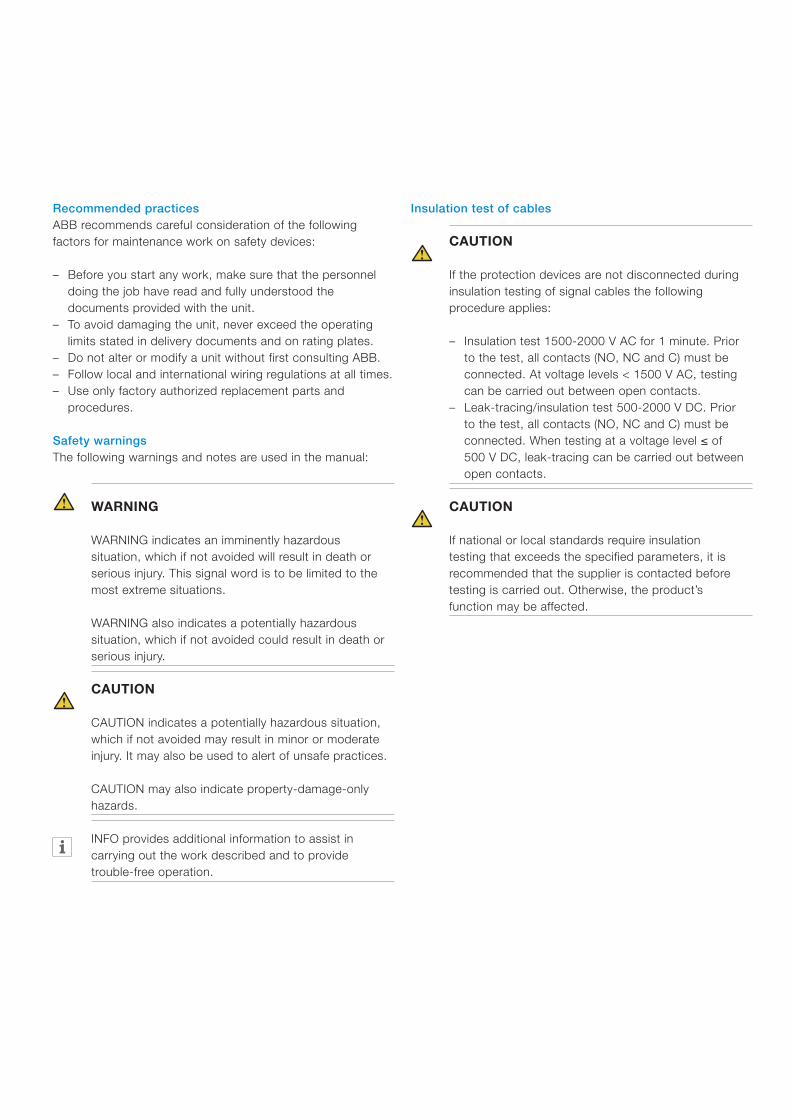
Recommended practicesABB recommends careful consideration of the following factors for maintenance work on safety devices:
– Before you start any work, make sure that the personnel doing the job have read and fully understood the documents provided with the unit.
– To avoid damaging the unit, never exceed the operating limits stated in delivery documents and on rating plates.
– Do not alter or modify a unit without first consulting ABB. – Follow local and international wiring regulations at all times. – Use only factory authorized replacement parts and
procedures.
Safety warningsThe following warnings and notes are used in the manual:
WARNING
WARNING indicates an imminently hazardous situation, which if not avoided will result in death or serious injury. This signal word is to be limited to the most extreme situations.
WARNING also indicates a potentially hazardous situation, which if not avoided could result in death or serious injury.
CAUTION
CAUTION indicates a potentially hazardous situation, which if not avoided may result in minor or moderate injury. It may also be used to alert of unsafe practices.
CAUTION may also indicate property-damage-only hazards.
INFO provides additional information to assist in carrying out the work described and to provide trouble-free operation.
Insulation test of cables
CAUTION
If the protection devices are not disconnected during insulation testing of signal cables the following procedure applies:
– Insulation test 1500-2000 V AC for 1 minute. Prior to the test, all contacts (NO, NC and C) must be connected. At voltage levels < 1500 V AC, testing can be carried out between open contacts.
– Leak-tracing/insulation test 500-2000 V DC. Prior to the test, all contacts (NO, NC and C) must be connected. When testing at a voltage level ≤ of 500 V DC, leak-tracing can be carried out between open contacts.
CAUTION
If national or local standards require insulation testing that exceeds the specified parameters, it is recommended that the supplier is contacted before testing is carried out. Otherwise, the product’s function may be affected.

Content1. Introduction ..........................................................................................................................5
1.1 Position of the sensors on tap-changers, type UBB ......................................................61.2 Position of the sensors on tap-changers, type VUBB ....................................................61.3 Position of the sensors on tap-changers, type UZ .........................................................71.4 Position of the sensors on tap-changers, type UC ........................................................81.5 Position of the sensors on tap-changers, type VUC ......................................................8
2. Pressure relay .......................................................................................................................102.1 General .........................................................................................................................102.2 Ratings .........................................................................................................................102.3 Before work ..................................................................................................................102.4 Installation .....................................................................................................................112.5 Check at commissioning ...............................................................................................12
2.5.1 Insulation test .........................................................................................................122.5.2 Function testing ......................................................................................................12
2.6 Service and trouble-shooting ........................................................................................132.7 Replacing the pressure relay .........................................................................................14
3. Oil flow relay .........................................................................................................................153.1 General .........................................................................................................................153.2 Ratings .........................................................................................................................153.3 Before work ..................................................................................................................153.4 Installation .....................................................................................................................163.5 Check at commissioning ...............................................................................................16
3.5.1 Insulation test .........................................................................................................163.5.2 Function testing ......................................................................................................17
3.6 Service and trouble-shooting ........................................................................................173.7 Replacing oil flow relay ..................................................................................................17
4. Pressure relief device (PRD) ..................................................................................................184.1 General .........................................................................................................................184.2 Ratings .........................................................................................................................184.3 Before work ..................................................................................................................184.4 Installation .....................................................................................................................194.5 Check at commissioning ...............................................................................................19
4.5.1 Insulation test .........................................................................................................194.5.2 Function test ..........................................................................................................19
4. 6 Trouble-shooting ..........................................................................................................194.7 Replacing .....................................................................................................................19
5. Oil level indicator ...................................................................................................................205.1 General .........................................................................................................................205.2 Ratings .........................................................................................................................205.3 Before work ..................................................................................................................205.4 Installation .....................................................................................................................205.5 Check at commissioning ...............................................................................................21

1ZSC000562-AAD en, Rev. 1 | Accessories and protection devices, Assortment guide 5
Standard IEC 60214-1 requires that at least one protection device is supplied with the tap-changer. The device must detect any faults related to the tap-changer as quickly as possible. Sensors detect faults by reacting to high pressure pulses or oil flows that are created in the event of internal failure in the tap-changer.
Fig. 1 schematically shows the position of the sensors on the tap-changer in relation to the transformer and expansion tank.
Oil conservator
Transformer cover
Tap-changer
Shaft
Bevel gear
Transformer tank
Shaft
Motor-drive mechanism
Oil flow relay
Pressure relay
Pressure relief device
Fig. 1. Main parts, on-load tap-changer type UC.
1. Introduction
If the transformer is painted after the sensors are installed, all ventilation holes on the sensors must be protected.
All sensors are supplied based on the selection made on the order form.
The sensors are designated their own position on each tap-changer. Figs. 2-8 show where the sensors are to be placed on the relevant tap-changer type.

6 Accessories and protection devices, Assortment guide | 1ZSC000562-AAD en, Rev. 1
Air release valve transformer
Pressure relief device
Flange (B) air release valves
Flange (A) pressure relay
Flange (C) pressure relay
Flange for temperature relay or temperature sensor TEC
Window, position indicator
Flange (B) temperature switch
Flange (A) connection to oil conservator
Flange for pressure relief device (when ordered)
Drain valve
Valve for oil filling, draining and filtration
Flange (C)
Drive shaft connection
Earthing terminal
1.1 Position of the sensors on tap-changers, type UBBFig. 2 shows the top section on tap-changer type UBB where the respective position of the sensors are marked. Alternative positions apply to positions A, B and C.
Fig. 2. Top section of tap-changer type UBB.
Fig. 3. Top section of tap-changer type VUBB.
1.2 Position of the sensors on tap-changers, type VUBBFig. 3 shows the top section on tap-changer type VUBB where the respective position of the sensors are marked. Alternative positions apply to positions A, B and C.
1ZSC000562-AAD en, Rev. 1 | Accessories and protection devices, Assortment guide 7
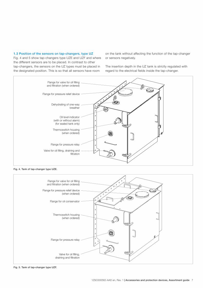
Flange for valve for oil filling and filtration (when ordered)
Flange for pressure relief device
Dehydrating of one-way breather
Oil level indicator (with or without alarm)
(for sealed tank only)
Thermoswitch housing (when ordered)
Flange for pressure relay
Flange for valve for oil filling and filtration (when ordered)
Flange for pressure relief device (when ordered)
Flange for oil conservator
Thermoswitch housing (when ordered)
Flange for pressure relay
Valve for oil filling, draining and filtration
Valve for oil filling, draining and filtration
Fig. 4. Tank of tap-changer type UZE.
Fig. 5. Tank of tap-changer type UZF.
1.3 Position of the sensors on tap-changers, type UZFig. 4 and 5 show tap-changers type UZE and UZF and where the different sensors are to be placed. In contrast to other tap-changers, the sensors on the UZ types must be placed in the designated position. This is so that all sensors have room
on the tank without affecting the function of the tap-changer or sensors negatively.
The insertion depth in the UZ tank is strictly regulated with regard to the electrical fields inside the tap-changer.

8 Accessories and protection devices, Assortment guide | 1ZSC000562-AAD en, Rev. 1
1.4 Position of the sensors on tap-changers, type UCFig. 6, 7 and 8 show top section on tap-changer type UC and the position of the sensors. Alternative positions apply to flanges A, B and C.
Pressure relief device (optional)
Flange (A) temperature relay or air release valve (optional)
Oil filling R1”, oil drain valve and oil filtration (or optionally
1” NPT)
Flange (B) pressure relay
Flange (C) air release valve OLTC
Air release valve transformer
Fig. 6. Top section of tap-changer type UCG and VUCG.
1.5 Position of the sensors on tap-changers, type VUCFig. 6 and 7 show top section on tap-changer type VUC and the position of the sensors. Alternative positions apply to flanges A, B and C.

1ZSC000562-AAD en, Rev. 1 | Accessories and protection devices, Assortment guide 9
Flange (A) temperature relay or air release valve (optional)
Oil filling R1", oil drain valve and oil filtration (or optionally
1" NPT)
Earthing terminal M12 To be grounded by user
Flange (B) pressure relay
Flange (C) connection to oil conservator
Air release valve transformer
Fig. 7. Top section of tap-changer type UCL and VUCL.
Fig. 8. Top section of tap-changer type UCC/UCD.
Flange for pressure relief device (optional)
Oil filling R1", oil drain valve and oil filtration (or optionally
1" NPT)
Air release valve transformer
Flange for pressure relief device
Flange to oil conservator
Air release valve tap-changer
Pressure relay

10 Accessories and protection devices, Assortment guide | 1ZSC000562-AAD en, Rev. 1
2.1 GeneralABB on-load tap-changers are supplied with a pressure relay as standard. If connected correctly, the pressure relay trips the transformer main circuit breakers in the event of excessive overpressure inside the tap-changer.
It is recommended to connect the pressure relay in the trip circuit of the power supply during testing of the transformer.
2.2 RatingsAuxiliary power 5 A at 125 V AC resistive 3 A at 250 V AC resistive 0.6 A at 125 V DC resistive 0.15 A at 125 V DC, L/R = 40 msTemperature Ambient -40 °C to 80 °C
2.3 Before work
WARNING
Before any work is carried out on the tap-changer: Make sure that the transformer is disconnected and earthing is properly carried out. Obtain a signed certificate from the engineer in charge.
Fig. 9. Pressure relay. Original fit to the left and retrofit part to the right.
WARNING
Disconnect all power sources before any work is carried out. Check that the power is disconnected by using a voltmeter.
WARNING
Do not take the transformer into service after a pressure relay trip without carrying out a careful inspection of the tap-changer. An authorized service technician must check all moving contacts and transition resistors as well as other vital parts. Disregarding this instruction may cause severe damage to the tap-changer and the transformer.
CAUTION
The pressure relay is a calibrated safety instrument. It must be handled with care at all times.
2. Pressure relay

1ZSC000562-AAD en, Rev. 1 | Accessories and protection devices, Assortment guide 11
2.4 Installation1. Check that the pressure relay is properly fitted to the quick
coupling. If not, secure the pressure relay by applying 25 Nm to the coupling.
2. Check that the relay setting corresponds with tap-changer type and the height of the conservator according to Table 1.
Make sure the tap-changer is not filled with oil before removing the flange.
3. Remove the cover from the flange at the indicated position (Figs. 2-8) and install the pressure relay. Make sure that the gasket is correctly fitted.
4. Remove the top cover from the pressure relay by unscrewing the two screws on the top cover. The screws are secured and stay in place if the cover is turned upside down.
5. Connect the cables to the bottom row on the terminal block. Fig. 10.
6. Perform commissioning check described in section 2.5.
Table 1. Set-point of the pressure relay.
Tap-changer type Set-point
50 kPa 100 kPa 150 kPa 200 kPa
UZ
Vert
ical
dis
tanc
e to
cons
erva
tor
tank
H < 4 m 4 m < H < 7 m
VUBB H < 7 m
UB H < 7 m 7 m < H < 12 m 12 m < H < 17 m
VUC H < 7 m
UC H < 7 m 7 m < H < 14 m
UC GSU 1) H < 4 m 4 m < H < 7 m 2)
1) GSU = Generator Step Up application.2) GSU Transformer with converter tank above ≥ 7 m please contact ABB.
Fig. 10. Installation.
Terminal block
Quick coupling
Top cover

12 Accessories and protection devices, Assortment guide | 1ZSC000562-AAD en, Rev. 1
Fig. 11. Test mode.
Valve handle in test
position
Test tap, R 1/8’’
2.5 Check at commissioning
WARNING
Before any work is started, make sure the power is disconnected.
Tools – Screwdriver 5 mm and 10 mm – Buzzer – 500 V DC power unit/insulation tester
2.5.1 Insulation test
CAUTION
If the protection devices are not disconnected during insulation testing of signal cables the following procedure applies:
– Insulation test 1500-2000 V AC for 1 minute. Prior to the test, all contacts (NO, NC and C) must be connected. At voltage levels < 1500 V AC, testing can be carried out between open contacts.
– Leak-tracing/insulation testing 500-2000 V DC. Prior to the test, all contacts (NO, NC and C) must be connected. When testing at a voltage level ≤ of 500 V DC, leak-tracing can be carried out between open contacts.
CAUTION
If national or local standards require testing that exceeds the specified parameters, it is recommended that ABB is consulted before testing is carried out. Otherwise, the product’s function may be affected.
The leakage current test is performed to verify that there is sufficient insulation to earth. All contacts NO, NC and C must be connected during the test. The test must not be performed between each contact to earth.
1. Connect all inputs and outputs (NO, NC and C). 2. Then power with 500 V DC for a maximum of 1 minute. 3. If the pressure relay shows the result < 100 MΩ it must be
replaced. See chapter 2.7.4. If no faults are indicated, continue with the function test.
2.5.2 Function testing
When function testing the pressure relay, observe caution when the pressure relay’s valve is set to test mode, as there is a risk that a small amount of oil will flow out of the valve.
1. Turn the handle on the valve 90° to the test position. See Fig. 11.
2. Connect an air pump with manometer to the test tap on the pressure relay. The air pump must be able to generate the pressure that the pressure relay is set to.

1ZSC000562-AAD en, Rev. 1 | Accessories and protection devices, Assortment guide 13
PRESSURE RELAY
P>
C
NO
NO
NC
NC
C
62
61
64
63
66
65
Fig. 13.
Fig. 12. Terminal output.
Valve handle in service position
3. Connect a buzzer to the terminal outputs according to Fig. 12. Test one output at a time. - output 61 (NO) with 62 (C) carry out point 4 and 5 - output 63 (NC) with 62 (C) carry out point 4 and 5 - output 64 (NO) with 65 (C) carry out point 4 and 5 - output 66 (NC) with 65 (C) carry out point 4 and 5
4. Apply the pressure shown by the pressure relay setting and register whether the switch gives a signal or not. Permitted deviation ± 10 %.
5. Note whether the signal disappears/recurs (NO or NC) when the pressure drops below the setting level. See Table 1.
6. If the pressure relay acts correctly, connect the cables from the control cabinet and reinstall the cover on the pressure relay. Ensure that all gaskets are correctly positioned.
7. Remove the air pump and refit the cover to the test output.
8. Set the valve handle back to service position. Fig. 13.9. Switch on the power.
2.6 Service and trouble-shootingIf the pressure relay has tripped, the tap-changer and/or transformer must be inspected thoroughly. Any faults must be repaired before the transformer resumes operation.
If both tap-changer and transformer work correctly, test the pressure relay according to chapter 2.5.2.

14 Accessories and protection devices, Assortment guide | 1ZSC000562-AAD en, Rev. 1
2.7 Replacing the pressure relay
CAUTION
It is not permitted to replace the microswitch or in any other way change the pressure relay settings. If the preset settings are in any way manipulated, this will impair the function of the pressure relay.
If the pressure relay fails to pass the insulation test and/or the function test, the pressure relay must be replaced. This is done without dismounting the valve, and only the pressure relay is replaced.
Tools required – Spanner (30 mm) – Screwdriver 5 mm and 10 mm
Spare parts required – Pressure relay – O-ring (17.1 x 1.6 mm)
WARNING
Be aware of the risk of slipping caused by oil spillage, when working on the transformer cover.
1. Set the three-way valve handle in test position (se Fig. 11)2. Disconnect the cable from the bottom row of the terminal
connection and open the cable gland. Pull the cable out through the cable gland.
3. Loosen the quick coupling and remove the pressure relay and the old O-ring inside the quick coupling.
4. Fit the new O-ring (17.1 x 1.6 mm) delivered together with the new pressure relay.
5. Mount the new pressure relay. Tightening torque approximately 20-25 Nm. The cable gland should point 180° opposite the valve handle.
6. Connect the cables.7. Tighten the cable gland, max 4-5 Nm.8. Carry out the test procedure according to section 2.5.2.
Fig. 14. Cable routing.
Bottom row, terminal connection
Cable gland
Fig. 15. Replacement of pressure relay.
New O-ring

1ZSC000562-AAD en, Rev. 1 | Accessories and protection devices, Assortment guide 15
3.1 GeneralThe tap-changer may be equipped with an oil flow relay. In the event of overpressure that will cause oil flow to the conservator, the oil flow relay responds with a signal that trips the transformer main circuit breakers or gives an alarm.
3.2 RatingsVoltageAC 230 VDC 24 V to 220 V
CurrentAC 2 A cos j > 0.5DC 2 A, t = L/R < 40 ms
3.3 Before work
WARNING
Before any work is carried out on the tap-changer: Make sure that the transformer is disconnected and earthing is properly carried out. Obtain a signed certificate from the engineer in charge.
WARNING
Disconnect all power sources before any work is carried out. Check that the power is disconnected by using a voltmeter.
WARNING
Do not take the transformer into service after an oil flow relay trip without carrying out a careful inspection of the tap-changer. An authorized service technician should carry out an inspection of all moving contacts and transition resistors as well as other vital parts. Disregarding this instruction may cause severe damage to the tap-changer and the transformer.
CAUTION
The oil flow relay is a calibrated safety instrument. It must be handled with care and protected against mechanical damage.
Fig. 16. Oil flow relay.
3. Oil flow relay

16 Accessories and protection devices, Assortment guide | 1ZSC000562-AAD en, Rev. 1
3.5 Check at commissioning
WARNING
Before any work is started, make sure the power is disconnected.
Tools – Spanner – 500 V DC power unit/insulation tester – Buzzer
3.5.1 Insulation testThe leakage current test is performed to verify that there is sufficient insulation to earth. The test must be performed with all contacts NO, NC and C connected.
1. Start by unscrewing the screws on the cover and removing the cover. If the test is performed from inside the control room, the cover for the oil flow relay does not need to be removed.
2. Connect all inputs and outputs (NO, NC and C).3. Then power with 500 VDC for a maximum of 1 minute. 4. If the oil flow relay shows the result < 100 MΩ it must be
replaced, see section 3.7.5. If no faults are indicated, continue with function test 3.5.2.
Fig. 17. Close up of flow direction arrow
Flow direction
3.4 Installation
CAUTION
Never connect two or more tap-changers to the same oil flow relay as this can cause false trip signals.
CAUTION
Pipes must be routed so that oil cannot flow between tap-changers without first passing the conservator.
The transformer manufacturer arranges the pipe routing between the conservator and tap-changer device on which the oil flow relay is to be placed.
Pipe bends must be avoided as far as is possible to obtain a free flow and prevent air bubbles in the system.
1. The oil flow relay must be positioned on the pipe up to the conservator, as close to the tap-changer as possible.
2. The angle of the pipe and oil flow relay up to the conservator must be between 2° and 4° to prevent gas bubbles getting stuck in the pipe.
3. Note the arrows that indicate the direction of flow of the oil flow relay; the arrow should point towards the conservator. See Fig. 17.
4. Make sure that the transport protection on the flanges are removed before the relay is installed on the pipes.
5. Connect the signal cable through the cable gland and connect to the terminal. Tighten the cable union to 4-5 Nm.
6. The cable gland that is not used must be sealed with a plug.

1ZSC000562-AAD en, Rev. 1 | Accessories and protection devices, Assortment guide 17
3.5.2 Function testingThe test is performed to ensure that the relay works as it should before the transformer is energized.
1. Remove the cover from the oil flow relay.2. Unscrew the plug for the test button. See Fig. 18. 3. Connect a buzzer to the terminal outputs according to
the description. Test one output at a time. Repeat the test procedure until all NO / NC contacts have been tested individually.
4. Depress the test button. Note that the signal is correct for the connection made.
5. When all signals function as they should, mount the cover and the plug back into place.
6. Then energize the oil flow relay.7. If the oil flow relay is defective, it must be replaced.
Continue with chapter 3.7.
3.6 Service and trouble-shootingTrouble-shooting the oil flow relay is carried out in the same way as when commissioning according to chapter 3.5.
CAUTION
If the transformer is operated after the oil flow relay has deployed, without opening the tap-changer and making a thorough inspection of the active part and rectifying any faults, this can cause serious damage to the tap-changer and transformer.
3.7 Replacing oil flow relayTools – Oil container/oil drum – Pump with connection to drain cock on the tap-changer. – Spanners for disassembling the switch with.
Procedure
CAUTION
Note the risk of slipping as oil can leak out from the pipe and onto the transformer cover.
CAUTION
Note that the direction of flow must be from the tap-changer to the expansion tank. See the arrow on the switch.
Fig. 18. Test button.
Unscrew the plug.Push the test button.
1. Close the shut-off valve on the pipe to the conservator.2. Drain oil through the designated valve on the tap-changer.
When the oil level has dropped below the oil flow relay, stop draining. It is not necessary to drain the entire tap-changer of oil.
3. Then unscrew the oil flow relay and install the new relay. All gaskets should be replaced. Check that all gaskets are correctly positioned and that all transport protection is removed.
4. Perform tests on the new relay according to chapter 3.5. Wait to perform point 6 until the oil has been pumped back in.
5. Once the new relay has been tested according to 3.5 and no faults have been detected, the amount of oil that was drained from the tap-changer must be refilled. Follow the instructions in the respective tap-changer’s installation instructions.
6. After the oil has been pumped back, check that the oil flow relay is in operating mode.

18 Accessories and protection devices, Assortment guide | 1ZSC000562-AAD en, Rev. 1
4.1 GeneralThe tap-changer may be equipped with a pressure relief device (PRD). In the event of overpressure the pressure relief device lets oil and gas out (to avoid rupture of the compartment), and gives an alarm signal. The pressure relief device is not intended to be the sole protective device on the tap-changer, but should be used together with a pressure relay and/or oil flow relay.
4.2 RatingsVoltage:AC 230 VDC 24 V to 220 V
Current:AC 2 A, cos j > 0.5DC 2 A, t = L/R < 40 ms
4.3 Before work
WARNING
Before any work is carried out on the tap-changer: Make sure that the transformer is disconnected and earthing is properly carried out. Obtain a signed certificate from the engineer in charge.
WARNING
Disconnect all power sources before any work is carried out. Check that the power is disconnected by using a voltmeter.
WARNING
Do not take the transformer into service after a pressure relief alarm without carrying out a careful inspection of the tap-changer. An authorized service technician should carry out an inspection of all moving contacts and transition resistors as well as other vital parts before re-commissioning the transformer. Disregarding this instruction may cause severe damage to the tap-changer and transformer.
CAUTION
The pressure relief device is a calibrated instrument. It must be handled with care and protected against mechanical damage.
Fig. 19. Pressure relief device 50M.
Fig. 20. Pressure relief device 50T.
4. Pressure relief device (PRD)

1ZSC000562-AAD en, Rev. 1 | Accessories and protection devices, Assortment guide 19
4.4 Installation
WARNING
Be aware of the risk of slipping caused by oil spillage, when working on the transformer cover.
1. Remove the protective cover or any previous relief device from the designated place on the tap-changer. See Figs. 2-8.
2. Install the pressure relief device and ensure that the gasket is correctly positioned.
3. Connect the cable to the junction box.
4.5 Check at commissioning
WARNING
Before any work is started, make sure the power is disconnected.
Tools – Screwdriver 5 mm – 500 V DC Power unit/Megger – Buzzer/Multimeter
4.5.1 Insulation testThe leakage current test is performed to verify that there is sufficient insulation to earth. The test must be performed with all contacts NO, NC and C connected.
1. Bridge all inputs and outputs (NO, NC and C). 2. Then power with 500 V DC for a maximum of 1 minute. 3. If the pressure relief device shows the result < 100 MΩ it must be
replaced, see section 4.3.4. If no faults are indicated, continue with function test 4.5.2.
4.5.2 Function test1. Connect a buzzer or multimeter to one input/output at a
time.2. Press the trigger.3. Note that the signal you get is correct based on the
connection diagram.4. Repeat the test procedure until all inputs and outputs have
been tested individually.5. When all signals function as they should, fit the cover for
the terminal terminals back into place.6. If the pressure relief device is defective, it must be
replaced. Continue with section 4.3.
4. 6 Trouble-shooting
If the pressure relief device has deployed, the indication pin must be in the raised position.
Follow the instructions in chapter 4.5.2.
4.7 Replacing 1. If the pressure relief device is deemed faulty, it must be
replaced. When replacing the pressure relief device, follow the description in chapter 4.3 and 4.5.
2. A faulty device must be returned to ABB.

20 Accessories and protection devices, Assortment guide | 1ZSC000562-AAD en, Rev. 1
5.1 GeneralThe oil level indicator is used as a supplement to other sensors, primarily on tap-changer type UZ.
5.2 RatingsAC 15 A at 125 V, 250 V and 480 VDC 0.5 A at 125 V, non-inductiveDC 0.25 A at 250 V, non-inductive
5.3 Before work
WARNING
Before any work is carried out on the tap-changer: Make sure that the transformer is disconnected and earthing is properly carried out. Obtain a signed certificate from the engineer in charge.
WARNING
Disconnect all power sources before any work is carried out. Check that the power is disconnected by using a voltmeter.
CAUTION
The oil level indicator is a calibrated monitoring instrument. It must be handled with care and protected against mechanical damage.
5.4 Installation1. Install the oil level indicator in the designated place
according to chapter 1.2. Note the insertion depth on the float when installing on
tap-changer type UZ.3. Connect the signal cables to the terminal box.4. Check the function by carefully moving the float up and
down according to Fig. 21.
Fig. 21.
5. Oil level indicator

1ZSC000562-AAD en, Rev. 1 | Accessories and protection devices, Assortment guide 21
OIL LEVEL INDICATOR
Signal atmin oil level
Signal atmax oil level
mC
NO
NO
NC
NC
C
1
2
5
3
6
4
5.5 Check at commissioning
WARNING
Before any work is started, make sure the power is disconnected.
Tools – Screwdriver 5 mm – 500 V DC Power unit/Megger – Buzzer/Multimeter
5.5.1 Insulation testThe leakage current test is performed to verify that there is sufficient insulation to earth. The test must be performed with all contacts NO, NC and C connected.
1. Connect all inputs and outputs (NO, NC and C). 2. Then power with 500 V DC for a maximum of 1 minute. 3. If the oil level indicator shows the result < 100 MΩ it must
be replaced.
Fig. 22.


Contact us
© C
opyr
ight
201
4 A
BB
, A
ll rig
hts
rese
rved
.
1ZS
C00
0562
-AA
D e
n, R
ev.
1, 2
014-
08-3
0ABB AB ComponentsSE-771 80 Ludvika, Sweden Phone: +46 240 78 20 00 Fax: +46 240 121 57 E-Mail: [email protected] www.abb.com/electricalcomponents