accordo family display audio processor - … · accordo™ family display audio processor data...
TRANSCRIPT

For further information contact your local STMicroelectronics sales office.
November 2016 DocID030009 Rev 1 1/20
STA1295
Accordo™ family Display Audio Processor
Data brief
Features
Core and infrastructure
– ARM Dual Core CortexA7 up to 650MHz, with NEON instructions
– Memory organization
– L1 Cache: 32K instruction, 32K data
– 256KB L2 Cache
– 700KB embedded SRAM
– 16/32 bit DDR3 Controller at 667MHz
– Serial QIO NOR interface
– 16bit Parallel NAND Controller
– 32-bit watchdog timer
– 16-channels DMA
– 8x 32-bit free running times/counters
– 4x 16-bit extended function timer (EFT) with input capture/output compare and PWM
– Real time clock (RTC) with fraction readout
Audio Subsystem
– Sound processing DSP (450MIPS)
– 6 stereo Channels Hardware sample rate converter
– 6x Audio DAC with 100 dB SNR
– 6x Rx/Tx Audio interfaces (I2S/ multi-channel ports, with SPI mode)
– 1x 98dB Stereo ADC for AUX IN/Tuner with internal switching logic (for 2 sources); SNR
– 2x differential Mono ADC for Voice/Tel-IN with internal switching logic; 105dB SNR
Media Interfaces
– 3x secure-digital multimedia memory card Interface
– 2x USB 2.0 Dual Role with integrated PHY; charger function supported
– 1x RMII/RGMII Ethernet AVB MAC
– SPDIF with CDROM block decoder support
Display Subsystem
– Multi-layer TFT dRGB Controller: up to 1080p
– Resistive Touch screen controller
– Video Input port, ITU-601/656
– 3D Graphics acceleration (GLES2.0)
– 2D graphics BitBlt/Blend engine
– H264 / Multi-Format Video Decoder
Embedded Secure vehicle interface microcontroller
– Dedicated Cortex M3 core
– 256KB Isolated embedded memory
– Secured NOR interface
– 3x CAN port, supporting FD CAN
I/O Interfaces
– 1x x8 channels 12-bits ADC
– 6 channel ADC for DC detection
– 3x I2C multi-master/slave interfaces
– 4x UART Controller
– 3x Synchronous Serial Port (SSP/SPI)
– 5x 32-bit GPIO ports
– JTAG based in-circuit emulator (ICE) with Embedded Trace Module
Operating Conditions
– VDD: 1.14V - 1.26V
– VDDIO: 3.3V ±10%
– DDR3 VDDQ 1.35
– ±5%;
– VDDIOON: 3.3V ±10%,
– Ambient temp range: -40/+85°C–
www.st.com

Contents STA1295
2/20 DocID030009 Rev 1
Contents
1 Description . . . . . . . . . . . . . . . . . . . . . . . . . . . . . . . . . . . . . . . . . . . . . . . . . 6
2 System description . . . . . . . . . . . . . . . . . . . . . . . . . . . . . . . . . . . . . . . . . . 7
2.1 Application processor . . . . . . . . . . . . . . . . . . . . . . . . . . . . . . . . . . . . . . . . 7
2.2 Memory architecture . . . . . . . . . . . . . . . . . . . . . . . . . . . . . . . . . . . . . . . . . . 7
2.2.1 Embedded memory . . . . . . . . . . . . . . . . . . . . . . . . . . . . . . . . . . . . . . . . . 7
2.2.2 DDR Controller . . . . . . . . . . . . . . . . . . . . . . . . . . . . . . . . . . . . . . . . . . . . 7
2.2.3 SQI NOR interface . . . . . . . . . . . . . . . . . . . . . . . . . . . . . . . . . . . . . . . . . . 7
2.2.4 Parallel memory interface . . . . . . . . . . . . . . . . . . . . . . . . . . . . . . . . . . . . 7
2.3 SD/MMC . . . . . . . . . . . . . . . . . . . . . . . . . . . . . . . . . . . . . . . . . . . . . . . . . . . 8
2.4 USB . . . . . . . . . . . . . . . . . . . . . . . . . . . . . . . . . . . . . . . . . . . . . . . . . . . . . . 8
2.5 Display controller . . . . . . . . . . . . . . . . . . . . . . . . . . . . . . . . . . . . . . . . . . . . 8
2.6 Touch Screen Controller . . . . . . . . . . . . . . . . . . . . . . . . . . . . . . . . . . . . . . . 9
2.7 Video Input Port . . . . . . . . . . . . . . . . . . . . . . . . . . . . . . . . . . . . . . . . . . . . . 9
2.8 3D Graphics Engine . . . . . . . . . . . . . . . . . . . . . . . . . . . . . . . . . . . . . . . . . . 9
2.9 2D Smart Graphics Accelerator . . . . . . . . . . . . . . . . . . . . . . . . . . . . . . . . 10
2.10 Multi-Format video decoder . . . . . . . . . . . . . . . . . . . . . . . . . . . . . . . . . . . 10
2.11 Sound subsystem . . . . . . . . . . . . . . . . . . . . . . . . . . . . . . . . . . . . . . . . . . . .11
2.11.1 Audio interfaces . . . . . . . . . . . . . . . . . . . . . . . . . . . . . . . . . . . . . . . . . . . 11
2.11.2 Routing and Sample Rate Converter . . . . . . . . . . . . . . . . . . . . . . . . . . . 12
2.11.3 Sound DSP . . . . . . . . . . . . . . . . . . . . . . . . . . . . . . . . . . . . . . . . . . . . . . 12
2.12 Ethernet MAC Controller . . . . . . . . . . . . . . . . . . . . . . . . . . . . . . . . . . . . . 13
2.13 System DMA . . . . . . . . . . . . . . . . . . . . . . . . . . . . . . . . . . . . . . . . . . . . . . 13
2.14 Secure CAN subsystem . . . . . . . . . . . . . . . . . . . . . . . . . . . . . . . . . . . . . 13
2.15 Crypto Accelerator Engine . . . . . . . . . . . . . . . . . . . . . . . . . . . . . . . . . . . . 14
2.16 General Purpose ADC . . . . . . . . . . . . . . . . . . . . . . . . . . . . . . . . . . . . . . . 14
2.17 GPIOs . . . . . . . . . . . . . . . . . . . . . . . . . . . . . . . . . . . . . . . . . . . . . . . . . . . 14
2.18 Generic Interfaces . . . . . . . . . . . . . . . . . . . . . . . . . . . . . . . . . . . . . . . . . . 14
2.18.1 4x UARTS . . . . . . . . . . . . . . . . . . . . . . . . . . . . . . . . . . . . . . . . . . . . . . . 14
2.18.2 3xI2C : . . . . . . . . . . . . . . . . . . . . . . . . . . . . . . . . . . . . . . . . . . . . . . . . . . 15
2.18.3 3xSSP/SPI ports supporting: . . . . . . . . . . . . . . . . . . . . . . . . . . . . . . . . . 15
2.19 Input Capture / Output compare . . . . . . . . . . . . . . . . . . . . . . . . . . . . . . . . 15

DocID030009 Rev 1 3/20
STA1295 Contents
3
2.20 Watchdog and timers . . . . . . . . . . . . . . . . . . . . . . . . . . . . . . . . . . . . . . . . 15
2.20.1 CortexR4 has: . . . . . . . . . . . . . . . . . . . . . . . . . . . . . . . . . . . . . . . . . . . . 15
2.20.2 CortexM3 has: . . . . . . . . . . . . . . . . . . . . . . . . . . . . . . . . . . . . . . . . . . . . 15
3 STA1295 Package information . . . . . . . . . . . . . . . . . . . . . . . . . . . . . . . . 16
3.1 Mechanical specification . . . . . . . . . . . . . . . . . . . . . . . . . . . . . . . . . . . . . 16
4 Order codes . . . . . . . . . . . . . . . . . . . . . . . . . . . . . . . . . . . . . . . . . . . . . . . 18
5 Revision history . . . . . . . . . . . . . . . . . . . . . . . . . . . . . . . . . . . . . . . . . . . 19

List of tables STA1295
4/20 DocID030009 Rev 1
List of tables
Table 1. LFBGA mechanical specification . . . . . . . . . . . . . . . . . . . . . . . . . . . . . . . . . . . . . . . . . . . . 16Table 2. LFBGA Package dimensions . . . . . . . . . . . . . . . . . . . . . . . . . . . . . . . . . . . . . . . . . . . . . . . 17Table 3. Device summary . . . . . . . . . . . . . . . . . . . . . . . . . . . . . . . . . . . . . . . . . . . . . . . . . . . . . . . . . 18Table 4. Document revision history . . . . . . . . . . . . . . . . . . . . . . . . . . . . . . . . . . . . . . . . . . . . . . . . . 19
DocID030009 Rev 1 5/20
STA1295 List of figures
5
List of figures
Figure 1. STA1295 overview . . . . . . . . . . . . . . . . . . . . . . . . . . . . . . . . . . . . . . . . . . . . . . . . . . . . . . . . 6Figure 2. STA1295 Sound subsystem . . . . . . . . . . . . . . . . . . . . . . . . . . . . . . . . . . . . . . . . . . . . . . . . 11

Description STA1295
6/20 DocID030009 Rev 1
1 Description
STA1295 is a fully automotive, power efficient System-On-Chip, targeting cost effective processing solution for modern Display Audio Systems. It features :
A powerful DualCortexA7 processor
A high performance 3D GPU engine
A multiformat video decoder engine
Multi-layer multi-format display controller
Digital Sound Processor
A complete set of standard connectivity interfaces
as well as a dedicated ARM – Cortex M3 controller for real-time CAN / Vehicle Interface Processing.
Figure 1. STA1295 overview
DocID030009 Rev 1 7/20
STA1295 System description
18
2 System description
2.1 Application processor
STA1295 processing capability relies on an ARM Dual Cortex-A7 running at up to 650MHz, delivering 2500+DMIPS with minimal heat dissipation requirements. The application processor has 32KB of instruction cache and 32KB of data cache, as well as 256KB of L2 cache for high throughput and low latency tasks. The dual core implementation is equipped with a dedicated PLL and power domain, in order to achieve best thermal/MIPS performance compromise in all application scenarios. The application processor is connected to the system via an efficient bus matrix infrastructure, implementing flexible QoS and trust zone features.
2.2 Memory architecture
2.2.1 Embedded memory
STA1295 embeds 700KB of 64bits SRAM memory clocked at 200MHz, which can be used for secure data storage.The whole embedded memory is also cacheable and can be accessed by DMA.
2.2.2 DDR Controller
DDR controller supports DDR3 JEDEC interface 16 or 32 bits wide, clocked at up to 667MHz, allowing an optimal solution for throughput intensive applications.
Such memory is cacheable, and can be accessed by DMA, and is flexibly configurable as secure/non-secure.
2.2.3 SQI NOR interface
The SQIO controller allows interfacing Serial Quad I/O flash memories up to 133MHz (SDR)
Main features are:
Direct flash memory access
Fast memory access through
page buffer (256 bytes)
Programmable single or quad I/O flash interface
SQI memory space can be partitioned in order to reserve a portion of the NOR device to the Secure CAN Subsystem.
2.2.4 Parallel memory interface
FSMC static memory controller, provides a generic 16-bits parallel interface suitable to connect SRAM and NAND devices. This peripheral allows execution in-place from SRAMs, as well as DMA accesses. Such interface can be used to store boot code into NAND.
System description STA1295
8/20 DocID030009 Rev 1
2.3 SD/MMC
STA1295 is equipped with 3 SDMMC controllers, which allow interfacing to either mass storage devices, or to WiFi modems.
Two interfaces implement the following specification:
eMMC - MultiMedia Card 4.4
– 26/52 MHz
– 1,4,8 bit of data
SD/SDIO 3.0
– 4 bit interface
– SDSC/SDHC/SDXC limited to 50MHz SDR freq.
Both interfaces can be used in conjunction with DMA to efficiently implement data transfer with minimal CPU load for handling interrupts.
A third controller, with dedicated DMA engine implementing :
eMMC - MultiMedia Card 4.51
– 26/52 MHz
– 1,4,8 bit of data
SD/SDIO 3.0
– 4 bit interface
– SDSC/SDHC/SDXC up to SDR50.
2.4 USB
STA1295 has two Dual role USB HS controllers, both with embedded PHY, allowing to efficiently connect to mass storage devices, as well as portable devices (phones, pads). Along with USB connectivity, STA1295 fully supports USB charger specification, implementing DCP protocol specification to provide high current to connected DP devices. The controller supports HS 480-Mbps using an EHCI Host Controller, as well as FS and LS modes through an integrated OHCI interface.
USB controller implements a bootable interface, useful for production flashing, as well as to debug system post production.
2.5 Display controller
Display controller works simultaneously on Multiple layers (up to 4), allowing an on-the-fly blending composition scheme from multiple frame buffers. Each buffer can have a different color format, and with each buffer user can specify cropping regions (windowing). A typical usage example is for blending a complex HMI rendered with 3D engine, on top of a video frame buffer and a rear-view camera buffer.
The controller can handle two symmetric display panels (only in WVGA mode), sharing the same data lane, with two separate frame buffer contents.
Video overlay
Supported color formats:
– RGB565, ARGB8888, YUV422, YUV 420 PLANAR
DocID030009 Rev 1 9/20
STA1295 System description
18
Gamma Correction (Using independent look-up tables for R,G,B)
Dithering
Configurable alpha blending modes, with either buffer alpha or constant alpha
2.6 Touch Screen Controller
Embedded 10-bit resistive touch screen controller allows to control 7-inches display touch screens.
2.7 Video Input Port
The Video Input Port (VIP) allows to grab images from external devices, supporting parallel CCIR-656 interface up to 54 MHz. Both embedded synchronization and external synchronization are supported. VIP supports both interlaced or progressive modes.
The VIP is synchronized with display controller to prevent tearing effects, and is used in conjunction with SGA to implement on the fly YUV->RGB color conversion and bilinear interpolated re-scaling.
2.8 3D Graphics Engine
STA1295 comes with a powerful 3D, allowing smooth HMI rendering with impressive transition effects quality, as well as Navigation and instrument clusters rendering. The 3D engine is based on a unified shader architecture, based on an ultrathreaded SIMD processor that performs as both vertex shader and fragment shader with IEEE 32bit floating point full precision. When used as a vertex shader it performs geometry transformations and lighting computations. When used as a fragment shader it applies texture data and computes color values for each pixel.
Open GL ES 2.0 / 1.1 compliance, including extensions; OpenVG 1.1
IEEE 32-bit floating-point pipeline
Ultra-threaded, unified vertex and fragment (pixel) shaders
Low bandwidth at both high and low data rates
Low CPU loading
Up to 12 programmable elements per vertex
Dependent texture operation with high-performance
Alpha blending
Depth and stencil compare
Point sampling, bi-linear sampling, tri-linear filtering, and cubic textures
Resolve and FastClear
8k x 8k texture size and 8k x 8k rendering target
Vertex DMA streams
With a performance of up to:
Vertex rate: 120M/sec
Pixel Rate: 240M/se
System description STA1295
10/20 DocID030009 Rev 1
2.9 2D Smart Graphics Accelerator
The aim of the Smart Graphic Accelerator (SGA) is to provide an efficient 2D primitive drawing tool that breaks down the MIPS and power consumption related to bit blitting and composition tasks
2D-Graphics features:
2D Rendering Speed: up to 208MPixel/s
Pixel, Line, Filled Triangle, Filled Rectangle primitives
Line-Stippling, Filling Pattern
Flat and Gradient colour fill (in triangle & rectangles)
Video Overlay features:
BitBlitting on Rectangle, Triangle shapes
Image Resizing (Bilinear Interpolation Filter or Sub/OverSampling)
Image Rotation (with any angle)
Colour Conversion (YUV-to-RGB or RGB-to-YUV, 16-235 clamping possible)
Transparency extraction (exact Colour Keying or Colour Cube (triple interval)
Colour Swap with Colour Keying
AlphaBlending of 3 sources to a destination, ROP boolean operations
Dithering operator
2.10 Multi-Format video decoder
The embedded video decoder is capable of decoding the following formats, with minimal CPU load:
H.264 Baseline, Main and High Profiles, levels 1 -4.1
SVC Scalable Baseline and High Profiles, Base Layer only
MPEG-4 Simple and Advanced Simple Profiles, levels 0 –5*
H.263 Profile 0, levels 10 –70
Sorenson Spark–WMV9 / VC-1 Simple, Main and Advanced Profile, levels 0 -3
MPEG-1&2 Main Profile, levels low, med and high–RealVideo8/9/10
DivX®3/4/5/6 support –Home Theatre Profile Qualification
On2 VP6, VP7 and VP8, Versions0-3
AVS JizhunProfile–JPEG, all common sampling formats
Along with video decoding features, the video decoder also implements video post processing functionality such as:
Re-scaling, with high quality filtering
Color conversion
Gamma correction
Dithering
Image cropping
Digital Zoom
DocID030009 Rev 1 11/20
STA1295 System description
18
Horizontal/vertical flip
2.11 Sound subsystem
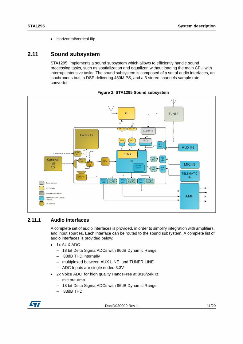
STA1295 implements a sound subsystem which allows to efficiently handle sound processing tasks, such as spatialization and equalizer, without loading the main CPU with interrupt intensive tasks. The sound subsystem is composed of a set of audio interfaces, an isochronous bus, a DSP delivering 450MIPS, and a 3 stereo channels sample rate converter.
Figure 2. STA1295 Sound subsystem
2.11.1 Audio interfaces
A complete set of audio interfaces is provided, in order to simplify integration with amplifiers, and input sources. Each interface can be routed to the sound subsystem. A complete list of audio interfaces is provided below:
1x AUX ADC
– 18 bit Delta Sigma ADCs with 96dB Dynamic Range
– 83dB THD internally
– multiplexed between AUX LINE and TUNER LINE
– ADC Inputs are single ended 3.3V
2x Voice ADC for high quality HandsFree at 8/16/24kHz:
– mic pre-amp
– 18 bit Delta Sigma ADCs with 96dB Dynamic Range
– 83dB THD
System description STA1295
12/20 DocID030009 Rev 1
– ADC is shared among Voice and TEL-IN lines with embedded multiplexer
– Both Voice and Tel-In lines are differential inputs.
3x Stereo DAC delivering:
– 100dB Dynamic Range unweighted
– 90dB THD
– DAC outputs are single ended 3.3V.
3x i2s IN
3x i2s OUT
1x MSP IN/OUT, TDM capable
1x SPDIF IN for CD/CDROM input with Hardware Block Decoder for CDROM error correction.
2.11.2 Routing and Sample Rate Converter
Each audio interface can be routed in both directions (IN/OUT) through sample rate converters, which allow normalizing the sampling rate to the sound processing engine. The audio routing infrastructure is designed to deliver high quality sample rate conversion on multiple channels, allowing simultaneous audio streams, such as BlueTooth Hands Free and audio media playback, to be handled without CPU load.
In order to generate multiple sampling rate audio frequencies, a dedicated fractional PLL is also provided. This PLL also allows an efficient implementation of iPOD playback, by dynamically adjusting the reconstructed audio sampling rate without CPU overload.
2.11.3 Sound DSP
STA1295 is equipped with three (3) 150MIPS 24-bit fixed point Harvard architecture DSPs (for a total of 450MIPS) dedicated to sound processing, fully integrated with the sound subsystem with a specific isochronous bus. DSPs are provided with an integrated sound processing library implementing effects like Gain, Balancing and Equalizer.
STA1295 is equipped with 2 DSPs configured as:
– 6 k x 32 bit program PRAM
– 4 k x 24 bit data XRAM
– 4 k x 24 bit data YRAM
And a third DSP configured as:
– 8k x 32 bit program PRAM
– 32k x 24 bit data XRAM
– 16k x 24 bit data YRAM
Each DSP is connected to other DSPs and audio peripherals by means of a programmable isochronous bus infrastructure which guarantees a controlled throughput and latency for all audio transfers.
DocID030009 Rev 1 13/20
STA1295 System description
18
2.12 Ethernet MAC Controller
Connection to Ethernet infrastructure is supported by the ETH MAC, which can be connected to an external phy with either RGMII or RMII interfaces. Ethernet MAC also implements AVB features, and is compatible with the following standards:
IEEE 1588-2008 for precision networked clock synchronization
IEEE 802.1AS-2011 and 802.1-Qav-2009 for Audio Video (AV) traffic
RGMII/RTBI specification version 2.6 from HP/Marvell
RMII specification version 1.2 from RMII consortium
MAC controller has separate channels or queues for AV data transfer in 100 Mbps and 1000 Mbps modes with single Tx/Rx FIFOs for all selected queues.
2.13 System DMA
DMA is designed to efficiently perform memory to memory, and memory to peripherals transfers, offloading such tasks from the processor, thus reducing interrupt handling load. DMA provides 16 independent channels which can be dynamically assigned to different data-path. Complex Scatter/gather transfers can be implemented by programming specific DMA command linked lists.
2.14 Secure CAN subsystem
STA1295 allows isolating critical code from main application by implementing a dedicated subsystem based on ARM Cortex-M3, along with:
256KB dedicated embedded SRAM
Interrupt controller
timers
CAN controller, implementing CAN and FD-CAN.
Dedicated GPIOs
Dedicated Wakeup lines
Back-up RAM in always on domain
Local RTC
Secure OTP, user programmable
All of the above can be completely isolated from the rest of the system. This subsystem can be dedicated to implement secure features, such as boot authentication, as well as interrupt intensive tasks to offload main CPU. The secure subsystem communicates with the application running on CortexR4 using a Hardware Mailbox interrupt based mechanism.
System description STA1295
14/20 DocID030009 Rev 1
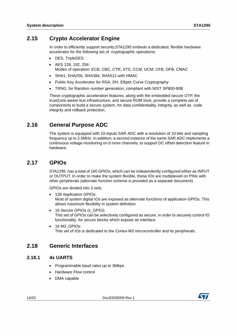
2.15 Crypto Accelerator Engine
In order to efficiently support security,STA1295 embeds a dedicated, flexible hardware accelerator for the following set of cryptographic operations:
DES, TripleDES
AES 128, 192, 256: Modes of operation: ECB, CBC, CTR, XTS, CCM, GCM, CFB, OFB, CMAC
SHA1, SHA256, SHA384, SHA512 with HMAC
Public Key Accelerator for RSA, DH, Elliptic Curve Cryptography
TRNG, for Random number generation, compliant with NIST SP800-90B
These cryptographic acceleration features, along with the embedded secure OTP, the trustZone aware bus infrastructure, and secure ROM boot, provide a complete set of components to build a secure system, for data confidentiality, integrity, as well as code integrity and rollback protection.
2.16 General Purpose ADC
The system is equipped with 10-inputs SAR ADC with a resolution of 10-bits and sampling frequency up to 2.5MHz. In addition, a second instance of the same SAR ADC implements a continuous voltage monitoring on 6 more channels, to support DC offset detection feature in hardware.
2.17 GPIOs
STA1295 has a total of 160 GPIOs, which can be independently configured either as INPUT or OUTPUT. In order to make the system flexible, these IOs are multiplexed on PINs with other peripherals (alternate function scheme is provided as a separate document).
GPIOs are divided into 3 sets:
128 Application GPIOs:Most of system digital IOs are exposed as alternate functions of application GPIOs. This allows maximum flexibility in system definition
16 Secure GPIOs (s_GPIO):This set of GPIOs can be selectively configured as secure, in order to securely control IO functionality, for secure blocks which expose an interface
16 M3_GPIOs:This set of IOs is dedicated to the Cortex-M3 microcontroller and its peripherals.
2.18 Generic Interfaces
2.18.1 4x UARTS
Programmable baud rates up to 3Mbps
Hardware Flow control
DMA capable

DocID030009 Rev 1 15/20
STA1295 System description
18
2.18.2 3xI2C :
Master/slave modes in multi-master environment
Multiple baud rates supported: 100/400/1000/3400Kbits/s
DMA capable
2.18.3 3xSSP/SPI ports supporting:
Motorola SPI-compatible interface
Texas Instrument synchronous serial interface
National Semiconductor Microwire interface
Unidirectional interface
DMA capable
2.19 Input Capture / Output compare
4 EFT (Enhanced Function timers) implement a very flexible input capture and output compare feature set. Each EFT block can provide 2 Input capture and 2 output PWM lines. EFT are based on 16-bit counters with dedicated pre-scaler.
2.20 Watchdog and timers
2.20.1 CortexR4 has:
2x MTU timers each providing access to four programmable 32-bit Free-Running decrementing Counters (FRCs)
1x Watchdog (WDT) unit that provides a way to recover from software crashes.
1x RTC counter clocked with 32KHz Oscillator.
2.20.2 CortexM3 has:
1x MTU timers providing access to four programmable 32-bit Free-Running decrementing Counters (FRCs)
1x Watchdog (WDT) unit that provides a way to recover from software crashes.

STA1295 Package information STA1295
16/20 DocID030009 Rev 1
3 STA1295 Package information
In order to meet environmental requirements, ST offers these devices in different grades of ECOPACK® packages, depending on their level of environmental compliance. ECOPACK® specifications, grade definitions and product status are available at: www.st.com. ECOPACK® is an ST trademark.
3.1 Mechanical specification
Table 1. LFBGA mechanical specification

DocID030009 Rev 1 17/20
STA1295 STA1295 Package information
18
Table 2. LFBGA Package dimensions

Order codes STA1295
18/20 DocID030009 Rev 1
4 Order codes
Table 3. Device summary
Order code Package Packing
STA1295
LFBGA
19x19x1.7mm
0.8mm pitch
Tray

DocID030009 Rev 1 19/20
STA1295 Revision history
19
5 Revision history
Table 4. Document revision history
Date Revision Changes
09-Nov-2016 1 Initial release.
STA1295
20/20 DocID030009 Rev 1
IMPORTANT NOTICE – PLEASE READ CAREFULLY
STMicroelectronics NV and its subsidiaries (“ST”) reserve the right to make changes, corrections, enhancements, modifications, and improvements to ST products and/or to this document at any time without notice. Purchasers should obtain the latest relevant information on ST products before placing orders. ST products are sold pursuant to ST’s terms and conditions of sale in place at the time of order acknowledgement.
Purchasers are solely responsible for the choice, selection, and use of ST products and ST assumes no liability for application assistance or the design of Purchasers’ products.
No license, express or implied, to any intellectual property right is granted by ST herein.
Resale of ST products with provisions different from the information set forth herein shall void any warranty granted by ST for such product.
ST and the ST logo are trademarks of ST. All other product or service names are the property of their respective owners.
Information in this document supersedes and replaces information previously supplied in any prior versions of this document.
© 2016 STMicroelectronics – All rights reserved