accuracy and precision of zero-echo-time, single- and
TRANSCRIPT
ORIGINAL RESEARCH Open Access
Accuracy and precision of zero-echo-time,single- and multi-atlas attenuationcorrection for dynamic [11C]PE2I PET-MRbrain imagingJoão M. Sousa1*† , Lieuwe Appel1,2†, Inés Merida3, Rolf A. Heckemann4, Nicolas Costes3, Mathias Engström5,Stergios Papadimitriou6, Dag Nyholm6,7, Håkan Ahlström1,2, Alexander Hammers8 and Mark Lubberink1,9
* Correspondence: [email protected]†João M. Sousa and Lieuwe Appelcontributed equally to this work.1Department of Surgical Sciences,Uppsala University, Uppsala,SwedenFull list of author information isavailable at the end of the article
Abstract
Background: A valid photon attenuation correction (AC) method is instrumental forobtaining quantitatively correct PET images. Integrated PET/MR systems provide nodirect information on attenuation, and novel methods for MR-based AC (MRAC) arestill under investigation. Evaluations of various AC methods have mainly focused onstatic brain PET acquisitions. In this study, we determined the validity of three MRACmethods in a dynamic PET/MR study of the brain.
Methods: Nine participants underwent dynamic brain PET/MR scanning using thedopamine transporter radioligand [11C]PE2I. Three MRAC methods were evaluated:single-atlas (Atlas), multi-atlas (MaxProb) and zero-echo-time (ZTE). The 68Ge-transmission data from a previous stand-alone PET scan was used as referencemethod. Parametric relative delivery (R1) images and binding potential (BPND) mapswere generated using cerebellar grey matter as reference region. Evaluation wasbased on bias in MRAC maps, accuracy and precision of [11C]PE2I BPND and R1estimates, and [11C]PE2I time-activity curves. BPND was examined for striatal regionsand R1 in clusters of regions across the brain.
Results: For BPND, ZTE-MRAC showed the highest accuracy (bias < 2%) in striatalregions. Atlas-MRAC exhibited a significant bias in caudate nucleus (− 12%) whileMaxProb-MRAC revealed a substantial, non-significant bias in the putamen (9%). R1estimates had a marginal bias for all MRAC methods (− 1.0–3.2%). MaxProb-MRACshowed the largest intersubject variability for both R1 and BPND. Standardized uptakevalues (SUV) of striatal regions displayed the strongest average bias for ZTE-MRAC (~10%), although constant over time and with the smallest intersubject variability.Atlas-MRAC had highest variation in bias over time (+10 to − 10%), followed byMaxProb-MRAC (+5 to − 5%), but MaxProb showed the lowest mean bias. For thecerebellum, MaxProb-MRAC showed the highest variability while bias was constantover time for Atlas- and ZTE-MRAC.
(Continued on next page)
© The Author(s). 2020 Open Access This article is licensed under a Creative Commons Attribution 4.0 International License, whichpermits use, sharing, adaptation, distribution and reproduction in any medium or format, as long as you give appropriate credit to theoriginal author(s) and the source, provide a link to the Creative Commons licence, and indicate if changes were made. The images orother third party material in this article are included in the article's Creative Commons licence, unless indicated otherwise in a creditline to the material. If material is not included in the article's Creative Commons licence and your intended use is not permitted bystatutory regulation or exceeds the permitted use, you will need to obtain permission directly from the copyright holder. To view acopy of this licence, visit http://creativecommons.org/licenses/by/4.0/.
EJNMMI PhysicsSousa et al. EJNMMI Physics (2020) 7:77 https://doi.org/10.1186/s40658-020-00347-2

(Continued from previous page)
Conclusions: Both Maxprob- and ZTE-MRAC performed better than Atlas-MRACwhen using a 68Ge transmission scan as reference method. Overall, ZTE-MRACshowed the highest precision and accuracy in outcome parameters of dynamic[11C]PE2I PET analysis with use of kinetic modelling.
Keywords: MRAC, ZTE, Atlas, MaxProb, Dopamine transporter, Binding potential, rCBF
IntroductionIn positron emission tomography (PET), photon attenuation correction (AC) is a
prerequisite for obtaining dependable images and quantifications. Photon attenuation is
the largest correction required in PET imaging as photon attenuation is inhomogen-
eous across tissues [1]. The amount of attenuation depends on spatially varying elec-
tron density. PET AC routines therefore require knowledge about the spatial
distribution of attenuation coefficients within the field of view (FOV) of the scanner,
represented as an attenuation map whose voxel values denote linear attenuation
coefficients [2–4].
Stand-alone PET systems are most often equipped with rotating 68Ge/68Ga transmis-
sion sources [5, 6]. This method is usually regarded as the gold standard for AC [7] as
it measures 511 keV photon attenuation directly, however not without some drawbacks
like noise and poor resolution. In PET/computed tomography (CT) systems, AC is
based on low-dose CT scanning [8], with CT images converted from Hounsfield units
to linear attenuation coefficients at 511 keV to obtain a suitable AC map for PET cor-
rection [9].
Integrated PET/magnetic resonance imaging (MRI) systems offer new opportunities
and challenges. Neurological disorders are key applications with a long clinical tradition
of combining functional information from nuclear medicine images with structural in-
formation from magnetic resonance imaging (MRI) to allow adequate quantification
across the brain. However, MRI provides no direct information on electron density that
can be used for AC [10, 11]. Instead, MRI can supply proton density, but its correlation
with gamma photon attenuation is highly nonlinear: the bone, in particular, has low
proton density and high electron density [12, 13]. Additional efforts are needed to de-
termine which AC method can be implemented as a routine in an image reconstruction
process.
Several approaches have been reported for MR-based attenuation correction (MRAC)
of PET brain data. Initially, a Dixon-based approach was implemented for PET MRAC.
This method is based on segmentation into tissue classes (i.e. air, lung, fat and soft tis-
sue) to which fixed attenuation coefficients are assigned [14–16]. As the Dixon-based
approach is primarily intended for whole-body PET-MR, the skull is not considered. As
a consequence, this MRAC method is a source of a substantial bias in brain studies, es-
pecially for cortical regions [17–19]. In parallel, various atlas-based MRAC approaches
were developed and evaluated. In this broad class of methods, a single atlas [20, 21] or
multiple atlases [22, 23] are applied to incorporate the bone in the MRAC map. As no
direct relationship exists between MRI and CT [3], various statistical methods have
been applied to convert MR intensities to a pseudo-CT with Hounsfield units for dis-
crimination of soft tissue, air and bone [24]. Generally, atlas-based MRAC methods
Sousa et al. EJNMMI Physics (2020) 7:77 Page 2 of 22

improve accuracy by including the skull and seem to perform within acceptable
quantitative limits [11, 25]. Most recently, segmentation of a zero-echo-time (ZTE)
MRI sequence [12, 26, 27] has been suggested for MRAC. With some resemblance
to ultrashort echo time (UTE) [28] and more recently RESOLUTE [29], ZTE was
designed to obtain signal from cortical bone with both lower acoustic noise and
reduced sensitivity to gradient fidelity artefacts [26, 30, 31]. As such, ZTE could be
used to incorporate the bone in a MRAC map [10, 12, 26]. Several clinical evalua-
tions demonstrated for static PET-data acquisitions that ZTE-based MRAC accom-
plished quantification with smaller errors than a single-atlas approach, both with
CT-AC [10, 32–37] or 68Ge-AC as reference [38]. Another rapidly emerging field
is the use of neural-networks to incorporate the bone in MRAC [39–42] but these
approaches are not considered here.
Until now, evaluations of various MRAC methods have mainly focused on static brain
PET, showing merely the tracer uptake or target-to-reference ratios. In an independent
multi-centre study where eleven MRAC methods were applied to a large cohort data
set of static fluorodeoxyglucose (FDG) PET/MR data, the average performance in PET
tracer uptake was generally within ± 5% of CT-AC [25]. However, dynamic brain PET
holds the compelling promise of in vivo functional imaging, i.e. following physiological
processes over time, or obtaining quantitative measures by means of tracer kinetic
modelling. Several recent studies have reported results for dynamic PET data using two
scanners, MRAC methods and radiotracers as well as different kinetic modelling ap-
proaches depending on the tracer kinetics [43–46]. To date, no study has compared the
multi-atlas method maximum probability algorithm (MaxProb) [43], favoured by Lade-
foged et al. [25], the single-atlas method and ZTE using the gold standard 68Ge-AC as
a reference, in a dynamic setting. MaxProb-MRAC builds on a database of brain MR/
CT image pairs and an application of a novel maximum probability method. In a
dynamic setting with the serotonergic 1a tracer [18F]MPPF, an acceptable amount of
bias in the estimated binding potential (BPND) was seen using CT-AC as reference.
In this study, we used 11C-labelled PE2I (N-(3-iodoprop-2E-enyl)-2β-carbomethoxy-
3β-(4-methyl-phenyl) nortropane), a radiotracer with high affinity to dopamine trans-
porters (DAT), especially in the striatum [47]. Kinetic modelling of dynamic [11C]PE2I
imaging data is able to determine both BPND, proportional to DAT availability, and
relative delivery (R1) reflecting relative cerebral blood flow, from one single brain scan
[48, 49]. These quantitative outcome measures are particularly important for the differ-
ential diagnosis in patients with Parkinsonism [50] and used in clinical routine at our
centre. Despite the promising evaluation reports of novel MRAC methods, it is still
unclear how these approaches might perform in a dynamic dataset with a specific
dopamine tracer and use of a kinetic modelling approach.
The aim of this study was to determine the validity of three different MRAC methods
in a setting with a dynamic [11C]PE2I PET brain scan on a PET-MR system, using68Ge-transmission AC as a reference method. We evaluated (1) a single-atlas method
(Atlas-MRAC) [11], (2) an MR sequence-based method (ZTE-MRAC) [12, 26, 27] and
(3) a multiple-atlas method (MaxProb-MRAC) [43, 51] in a dynamic [11C]PE2I PET
dataset acquired on an integrated digital time-of-flight PET-MR system. Individual
transmission scans acquired on a stand-alone PET system were used as the reference
method (68Ge-MRAC), directly measuring attenuation at 511 keV.
Sousa et al. EJNMMI Physics (2020) 7:77 Page 3 of 22

MethodsParticipants and data acquisition
The participants and data acquisition have previously been described [38]. This study
was approved by the Regional Board of Medical Ethics in Uppsala as well as the Radi-
ation Ethics Committee of Uppsala University Hospital, and all participants consented
in writing to take part in the study before inclusion. The study comprised nine patients
with Parkinsonism (5 females, 4 males; median age 72 years, range 49–82). Previously,
each participant had undergone a 10-min transmission scan using three rotating 68Ge
rod sources on an ECAT Exact HR+ scanner (Siemens, Knoxville, USA), prior to injec-
tion of any radioactivity. Participants then underwent a dynamic brain PET scan using11C-PE2I on a 3-T time-of-flight (TOF) PET/MR (SIGNA PET/MR, GE Healthcare,
Waukesha, USA) system.
An 80-min PET scan was acquired in list mode, starting simultaneously with intra-
venous bolus administration of 5MBq/kg [11C]PE2I using an infusion pump, and di-
vided into 22 time frames of increasing duration (4 × 60s, 2 × 120 s, 4 × 180 s, 12 ×
300 s). Relevant MR sequences were acquired during the first five minutes of the
[11C]PE2I PET scan to avoid misalignment due to head movements. Three MR
sequences were acquired during the [11C]PE2I PET scan: (1) a T1w 3D LAVA Flex that
was later used for Atlas-MRAC (duration 18 s, 1 number of excitations (NEX), FOV
500mm, slice thickness 5.2 mm, overlap 2.6 mm, matrix 256 × 256 and 5° flip angle);
(2) a proton-density ZTE sequence (duration 153 s, 4 NEX, FOV 260mm, slice thick-
ness 1.4 mm, no slice gap, matrix 192 × 192, flip angle 0.8°); and (3) a 3D T1w brain
volume imaging sequence that was later used for definition of regions of interest and as
the target for MaxProb-MRAC registration (gradient-echo, duration 272 s, 1 NEX, FOV
250mm, slice thickness 1 mm, matrix 256 × 256, flip angle 12°, TI 450 ms).
Generation of MR attenuation correction maps
For each participant, the following MR attenuation correction maps (MRAC) were
produced:
Atlas-MRAC—The single-atlas-based method [11, 20] consisted of three steps: (1)
application of a Hessian matrix to enhance bone structures in the T1w image, (2)
pseudo-CT generation by registration of the enhanced image to a head atlas based on
CT scans of 50 participants, and (3) standard energy conversion and resampling of the
pseudo-CT, resulting in an AC map with dimensions of 128 × 128 × 89 voxels (4.68 ×
4.68 × 2.78 mm). This method was vendor-provided (software version MP26) as a
standard application for our PET/MR system when the study was initiated.
ZTE-MRAC—In this procedure, an intensity equalization to a ZTE image was
followed by logarithmic image rescaling to enhance bone tissue. Next, a mask was used
to isolate the brain data, thus removing bed and coil information. A sequence of
thresholding operations was then applied to the subject’s brain image to segment the
bone and air regions by fitting a Gaussian to the main image histogram peaks.
Remaining internal air compartments were further segmented by means of histogram
thresholding. ZTE bone voxels are assigned continuous attenuation coefficients using a
ZTE-intensity HU calibration curve as described in [10, 12, 26, 33]. Finally, the resulting
MRAC image was co-registered and resampled to the subjects’ individual Atlas-MRAC by
Sousa et al. EJNMMI Physics (2020) 7:77 Page 4 of 22

applying 6-parameter rigid-body registration creating the ZTE-MRAC map. This method
is also a vendor-implemented process (GE PET Reconstruction Toolbox MP26), but
during data acquisition still under development [12, 26, 27].
MaxProb-MRAC—This method utilized a database of 40 corresponding MR and
CT images [43, 51]. Processing steps were executed using an in-house MATLAB
pipeline (MATLAB R2017a, Mathworks Inc., Natick, MA, USA). Each MR image
from the database was paired with the participant’s high-resolution T1w image,
and masking was applied to both images to reduce extraneous image information.
In the following registration steps, the masked MR image pair was aligned by
means of affine registration followed by non-rigid registration using normalized
mutual information as the similarity measure (register github.com/BioMedIA/
MIRTK). Subsequently, the transformation matrices acquired from the non-rigid
registration of MR images were applied to the corresponding CT images, yielding a
database of co-registered MR/CT image pairs. In the next step, the co-registered
CTs were segmented into three tissue classes defined by intensity thresholds (air: <
− 500 HU, soft tissue: − 500–300 HU, bone: > 300 HU [20]. Each voxel tissue class
of the target subject space was then assigned to a tissue class by majority voting of
tissue class labels across the registered CT database. Finally, a voxel-wise pseudo-
CT was generated by averaging CT Hounsfield values of atlases belonging to the
majority class for the corresponding voxel. A bilinear energy conversion [52] was
performed as the last step of attenuation map computation. The resulting MRAC
image was rigidly co-registered and resampled to the participant’s individual Atlas-
MRAC. Thereafter, the MaxProb-MRAC image was completed by adding, from the
Atlas-MRAC map, the neck information missing due to differences in axial FOV
between the images retrieved from the MR/CT database (216 mm) and the PET/
MR scanner (250 mm).68Ge-AC—Attenuation maps were reconstructed from the 68Ge transmission scan
using ordered subset expectation maximisation (OSEM) with 6 iterations, 8 subsets and
a 4 mm Hanning post-filter, dimensions 128 × 128 × 63 voxels (5.15 × 5.15 × 2.43
mm). Thereafter, a mask was applied to strip the AC map from the bed and head sup-
port as well as noise surrounding the head, followed by rigid co-registration and resam-
pling to the participant’s individual Atlas-MRAC map. As the axial FOV differed
between the stand-alone PET (155 mm) and PET/MR scanner (250 mm), the 68Ge-AC
map was completed with the corresponding information concerning the neck and top
of the head from the Atlas-MRAC map.
As a common step for all generated MRAC maps, coil and bed AC map templates
were then incorporated, applying an in-house MATLAB pipeline (MATLAB R2017a,
Mathworks Inc., Natick, MA, USA).
Image reconstruction
The dynamic [11C]PE2I PET data were reconstructed using time-of-flight OSEM
with 2 iterations, 28 subsets, 5 mm Gaussian post-filter, 128 × 128 reconstruction
matrix and 300 mm FOV. MRAC was performed in four ways as described in the
previous section. Further, all appropriate corrections for quantitative image recon-
struction were applied.
Sousa et al. EJNMMI Physics (2020) 7:77 Page 5 of 22

[11C]PE2I image analysis
The methodology and validation for voxel-level analysis of dynamic [11C]PE2I scans
have been previously reported [48, 49].
Following this approach, the reconstructed [11C]PE2I PET images were realigned to
correct for interframe patient movements using an early (0–3 min) [11C]PE2I summed
image as reference using an in-house MATLAB 2018 script. Interframe motion was es-
timated in this way for the PET images corrected for AC using 68Ge-AC, and the same
transformation were applied to the other three dynamic data sets. Subsequently, the
same summed image was used for co-registration of the 3D T1w MRI scan based on a
6-parameter rigid transformation, to achieve positional alignment. Then, MR images
were segmented into grey matter, white matter, and cerebrospinal fluid using Statistical
Parametric Mapping (SPM12; Wellcome Trust Center for Neuroimaging, University
College London, UK). Grey matter volumes of interest (VOI) were established on the
T1w structural MR images using an automated probabilistic template as implemented
in the PVElab software [53] for cortical and limbic regions. For striatal regions, MAPE
R [54], a technique optimized for segmentation of atrophic brains, was used to achieve
a more accurate delineation. All VOIs were projected over the dynamic scans to
generate time-activity curves (TACs).
Parametric images were generated from the [11C]PE2I scan using receptor parametric
mapping (RPM) with cerebellar grey matter as a reference region [55]. RPM is an im-
plementation of the simplified reference tissue model, SRTM [56], with a set of prede-
fined basis functions to linearize the model and estimate voxel-wise R1 and BPND that
can be applied to [11C]PE2I. The parametric [11C]PE2I BPND images demonstrate spe-
cific binding of [11C]PE2I to DAT directly proportional to DAT density (availability)
and therefore mainly show the deep grey matter of the striatum. The parametric
[11C]PE2I R1 images display relative cerebral blood flow, which reveals overall brain
functional activity. This procedure was repeated for all four [11C]PE2I PET data sets.
Finally, the grey matter VOIs on the co-registered MR images were projected on the
various parametric [11C]PE2I R1 and BPND images from all four datasets.
Volumes of interest
Quantification of BPND was evaluated separately for the caudate nucleus and putamen
as well as for the whole dorsal striatum (volume-weighted average of the putamen and
caudate). These regions normally have high DAT availability, but a pronounced
reduction is often observed in persons with Parkinsonism [49].
Evaluation of the quantification of R1 was based on four clusters of VOIs across the
brain: anterior cortical regions (cingulate, frontal gyrus), posterior cortical regions (occipi-
tal cortex, parietal cortex, somatosensory-motor cortex), dorsal striatal regions (caudate
nucleus, putamen) and limbic regions (amygdala, hippocampus, hypothalamus, thalamus)
[49]. In addition, whole-brain grey matter (WB) was determined as an overall measure.
Evaluation of MRAC maps
All participants’ MRAC maps were converted to MNI space using SPM12. Mean
MRAC images for all four methods were calculated, and bias compared to 68Ge-AC
was calculated at the voxel level as follows:
Sousa et al. EJNMMI Physics (2020) 7:77 Page 6 of 22
Biasi ¼ MRACi −68GeAC ð1Þ
where i refers to the three MRAC methods being compared to 68Ge-AC.
Attenuation maps were assessed on soft tissue and bone compartments. A large VOI
was drawn over the 68Ge-AC map soft tissue and copied to the other AC methods. A
bone mask was created by simple segmentation of the ZTE map followed by 2-pixel
erosion to reduce the probability of coinciding with other tissues. The bone mask was
then transferred to all other AC methods. Mean bias values were calculated for both
soft tissue and bone.
Evaluation of [11C]PE2I BPND and R1 estimates
[11C]PE2I BPND and R1 images for each subject were converted to MNI space using
SPM12. Mean [11C]PE2I BPND and R1 images for all four methods were calculated, and
bias (Eq. 1) compared to 68Ge was calculated at the voxel level for the defined VOIs.
For quantitative assessment, we used relative differences (% bias; see Eq. 2) in BPND
and R1 as a measure of accuracy, while standard deviation of the bias was taken as a
measure of precision.
Biasi %ð Þ ¼ PETMRACi − PET 68Ge − AC
PET 68Ge − AC� 100 ð2Þ
with i referring to the three evaluated MRAC methods.
Correlation analysis (Spearman) and Deming regression were used to assess the
degree of agreement between BPND and R1 values obtained using each of the evaluated
MRAC methods and the reference method (68Ge-AC).
Statistical analysis was performed using GraphPad Prism 6 (GraphPad Software, La
Jolla, CA, USA). Significant differences in bias (p < 0.05) between each evaluated
MRAC method and 68Ge-AC as reference method were assessed using a Friedman test
with post-hoc tests (comparison to 68Ge-AC) and Dunn’s correction.
Evaluation of time-activity curves
Previous reports indicate that effects of attenuation correction on uptake over time can
be inhomogeneous [29, 43, 44, 57] and may potentially affect the accuracy and preci-
sion of the parameters estimated by kinetic modelling. We therefore examined relative
bias and its SD in [11C]PE2I standardized uptake values (SUV) over time. This was
done for striatal regions with a high DAT density and the reference region (cerebellum)
used after implementation of Atlas-, ZTE- and MaxProb-MRAC.
ResultsMRAC maps
The MRAC maps for 68Ge, Atlas, ZTE and MaxProb of a representative subject are
presented in Fig. 1. Each MRAC map exhibited distinct qualitative features mainly
inherent to how the maps were generated. The 68Ge-AC map displayed images with
heterogeneous signal in the soft tissue due to noise as a result of low-count statistics.
The ZTE-MRAC map based on MRI methodology had the highest resolution, although
the sinus regions are not well defined. The Atlas- and MaxProb-MRAC maps were
Sousa et al. EJNMMI Physics (2020) 7:77 Page 7 of 22
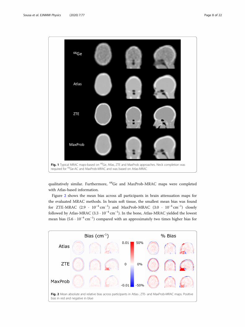
qualitatively similar. Furthermore, 68Ge and MaxProb-MRAC maps were completed
with Atlas-based information.
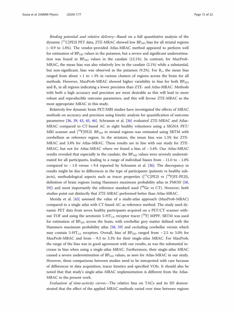
Figure 2 shows the mean bias across all participants in brain attenuation maps for
the evaluated MRAC methods. In brain soft tissue, the smallest mean bias was found
for ZTE-MRAC (2.9 · 10−4 cm−1) and MaxProb-MRAC (3.0 · 10−4 cm−1) closely
followed by Atlas-MRAC (3.3 · 10−4 cm−1). In the bone, Atlas-MRAC yielded the lowest
mean bias (5.6 · 10−4 cm−1) compared with an approximately two times higher bias for
Fig. 1 Typical MRAC maps-based on 68Ge, Atlas, ZTE and MaxProb approaches. Neck completion wasrequired for 68Ge-AC and MaxProb-MRAC and was based on Atlas-MRAC
Fig. 2 Mean absolute and relative bias across participants in Atlas-, ZTE- and MaxProb-MRAC maps. Positivebias in red and negative in blue
Sousa et al. EJNMMI Physics (2020) 7:77 Page 8 of 22

MaxProb-MRAC (13 · 10−4 cm−1) and three times higher bias for ZTE-MRAC (18 ·
10−4 cm−1). In the sinus region, an evident bias was detected in all maps where the
highest overestimation was noticed for ZTE-MRAC.
Binding potential
Mean parametric BPND images were similar for all MRAC methods (Fig. 3a). Mean bias
images of BPND displayed an obvious negative bias in the striatum in case of Atlas-
MRAC while these images pointed to a relatively small striatal bias for ZTE- and
MaxProb-MRAC (Fig. 3b). Various bias patterns between MRAC methods were found
for extrastriatal regions but this might also be due to low DAT density (see Fig. 3b).
The relative bias of the striatal BPND estimates is presented in Fig. 4a. Atlas-MRAC
resulted in a substantial negative relative bias for the caudate and the entire striatum,
but only a small bias for the putamen. For ZTE, a minor relative bias in BPND with a
low variability was observed for the putamen and striatum, whereas a greater variability
between participants was noted for the caudate. For all regions, MaxProb showed con-
siderable variability with both positive and negative bias percentages. There was no ob-
vious relationship between the magnitude of the reference values (BPND based on 68Ge-
AC) and bias percentages.
The Deming regression lines demonstrated a high degree of agreement for ZTE- and
MaxProb-MRAC compared to the reference method in all brain regions (Fig. 4b). In
contrast, the regression lines for Atlas-MRAC exhibited a deviation from the identity
line, indicating a negative bias compared to the reference method.
Table 1 lists quantitative values related to accuracy (% bias) and precision (SD of %
bias) for estimated BPND values as well as measures of consistency between evaluated
and reference MRAC (correlations, regression parameters). ZTE-MRAC results showed
little bias for all regions (< 2%) with a generally high precision. The highest bias was
found for Atlas-MRAC in the caudate (approximately − 12%) which differed
Fig. 3 a Mean BPND images using 68Ge- and Atlas-, ZTE- and MaxProb-MRAC showing striatal DAT density.b Mean bias images of BPND illustrating voxel-wise differences in BPND between each MRAC methodand 68Ge-MRAC
Sousa et al. EJNMMI Physics (2020) 7:77 Page 9 of 22

significantly from 68Ge-AC (p < 0.05). MaxProb also showed a relatively large mean
bias in the putamen (about 9%) but did not deviate significantly from 68Ge-MRAC.
MaxProb-MRAC showed the lowest precision in all regions. Only the bias obtained for
the caudate with the Atlas approach was statistically significant.
In general, strong correlations with 68Ge-AC were established for all three evaluated
MRAC- methods in all regions (r ≥ 0.95).
Estimated BPND values and relative bias for the evaluated MRAC methods are
illustrated with boxplots in Fig. 5. The median BPND of the investigated brain regions
differed only modestly within regions (Fig. 5a). The relative bias was low for ZTE-
MRAC while MaxProb-MRAC showed the lowest precision indicated by the size of the
boxes and bars (Fig. 5b).
Fig. 4 a Relative differences in BPND (% bias) plots of BPND when comparing Atlas-, ZTE- or MaxProb-MRACto 68Ge-AC (gold standard) for striatal brain regions. b Relationship between BPND using various MRACmethods and 68Ge-AC as reference, where solid lines represent Deming regressions and dashedline identity
Table 1 BPND–mean % bias and precision (SD of % bias) as well as correlation coefficient (r) forstriatal regions when comparing Atlas-, ZTE- and MaxProb-MRAC against 68Ge-AC. Additionally, theslope and intercept of Deming regression lines are given
Brain region MRAC % bias SD r Slope Intercept
CN Atlas − 12.09* 5.36 0.98 0.88 − 0.01
ZTE − 0.85 7.41 0.95 1.07 − 0.18
MaxProb 2.11 13.24 0.98 0.98 0.06
PUT Atlas 0.52 6.04 1.00 0.97 0.07
ZTE 1.83 3.81 0.95 1.02 − 0.02
MaxProb 9.19 10.78 1.00 0.98 0.29
STR Atlas − 5.43 3.31 0.98 0.94 0.00
ZTE 0.30 3.95 0.97 1.05 − 0.11
MaxProb 5.48 10.62 1.00 0.99 0.17
CN caudate nucleus, PUT putamen, STR striatum*p value < 0.05. Friedman test with post-hoc tests (comparison to 68Ge-AC) and Dunn’s correction
Sousa et al. EJNMMI Physics (2020) 7:77 Page 10 of 22

Relative delivery
Mean parametric R1 images, representing relative cerebral blood flow and overall brain activ-
ity, are presented in Fig. 6a and show similar patterns for all four MRAC methods. Mean bias
images of R1 indicated mostly a positive bias throughout the brain regardless of the MRAC
method used (Fig. 6b). Further, these images pointed to a distinct positive bias in the anterior
part of the brain for Atlas-MRAC and especially MaxProb-MRAC. Negative bias was evident
in the posterior part of the brain for Atlas-MRAC and to a lesser degree for ZTE.
The relative bias of R1 estimates for various clusters of brain regions is displayed in
Fig. 7a. Generally, the relative bias of R1 was within a range of −/+ 5%. However, for all
brain clusters, the variability was greater for MaxProb-MRAC compared to the other
MRAC methods. R1 estimates of WB had a small bias and variability for all MRAC
methods. The individual regional R1 bias values were generally in the range of − 5 to
15%. Striatal R1 estimates contained mainly a positive bias, while the other regions
contained both positive and negative % bias.
Strong and similar relationships were found between the R1 estimates from the inves-
tigated MRAC methods and the reference method (Fig. 7b). All Deming regression
lines were close to the line of identity, displaying a high degree of agreement.
Fig. 5 Boxplots for estimated BPND (a) and % bias (b) in BPND when comparing Atlas-, ZTE- or MaxProb-MRAC to 68Ge-AC for the caudate (CN), putamen (PUT), and entire striatum (STR). Bars and whiskersrepresent median and first and third quartile. * p value < 0.05
Fig. 6 a Mean parametric R1 images using 68Ge- and Atlas-, ZTE- and MaxProb-MRAC. b Mean bias imagesof R1 illustrating voxel-wise differences in R1 between each MRAC method and 68Ge-AC
Sousa et al. EJNMMI Physics (2020) 7:77 Page 11 of 22

The outcome of the evaluation of R1 estimates (accuracy, precision and degree of
agreement) is given for various clusters of brain regions in Table 2. For all investigated
MRAC methods, the mean bias percentages were low and within a range of − 1.0 to +
3.5%. A modest negative mean bias was found for posterior cortical regions using Atlas-
or ZTE-MRAC, whereas all other mean bias values were positive. Based on the SD of
the mean bias percentages, ZTE-MRAC showed the highest precision and MaxProb-
MRAC the lowest precision, which was consistent for most clusters of brain regions.
High correlations between the evaluated MRAC methods and the reference method
were attained for all brain regions (0.92–1.00).
Fig. 7 a Relative differences in R1 (% bias) plots of R1 when comparing Atlas-, ZTE- or MaxProb-MRAC to68Ge-AC as gold standard for different clusters of brain regions. b Relationship between R1 values derivedusing various MRAC methods and 68Ge-AC as reference, where solid lines represent Deming regressionsand dashed line identity
Table 2 R1 mean % bias, precision (SD of % bias) and correlation coefficient (r) for all clusters ofbrain regions when comparing Atlas-, ZTE- and MaxProb-MRAC against 68Ge-MRAC. Additionally,slope and intercept of Deming regression lines are given
Brain region MRAC % bias SD r Slope Intercept
WB Atlas 0.44 1.67 0.98 1.12 -0.10
ZTE 0.99 1.21 1.00 0.94 0.06
MaxProb 1.37 2.69 0.93 1.11 -0.08
ACR Atlas 1.54* 2.85 0.98 1.10 -0.07
ZTE 1.14 2.49 0.97 1.06 -0.04
MaxProb 2.85* 4.12 0.96 1.07 -0.03
PCR Atlas -0.95 2.91 0.97 1.05 -0.05
ZTE -0.51 1.47 0.99 0.99 0.00
MaxProb 1.14 4.38 0.92 1.06 -0.04
STR Atlas 2.44* 2.53 0.99 0.99 0.03
ZTE 2.71* 2.06 0.99 0.99 0.03
MaxProb 3.17* 3.67 0.98 1.01 0.02
LR Atlas 2.29* 3.26 0.97 1.03 -0.01
ZTE 3.09* 3.33 0.97 1.00 0.02
MaxProb 0.35 3.94 0.98 1.06 -0.04
ACR anterior cortical regions, PCR posterior cortical regions, STR striatal regions, LR limbic regions, WB whole brain*p value < 0.05. Friedman test with post-hoc tests (comparison to 68Ge-AC) and Dunn’s correction
Sousa et al. EJNMMI Physics (2020) 7:77 Page 12 of 22

Boxplots for estimated R1 values and relative bias are given for all MRAC methods
used in Fig. 8. Only minor differences in median and the variability of R1 estimates
were found between the four MRAC methods within each brain cluster (Fig. 8a).
Significant differences in relative bias were noted in the striatum for all three MRAC
methods relative to 68Ge-MRAC, in anterior cortical regions for Atlas- and MaxProb-
MRAC and in limbic regions for Atlas and ZTE, Table 2 and Fig. 8b.
Evaluation of time-activity curves
Figure 9 shows the bias and its SD over time in SUV for the three evaluated
MRAC methods compared to 68Ge-MRAC, in striatal regions and cerebellum.
Particularly, in the caudate, the biases on TACs had variable shapes: a strong and
slightly decreasing bias over time for ZTE-MRAC (+ 10% to7%), a relatively low
bias for MaxProb-MRAC (+ 5 to − 5%) for MaxProb-MRAC and a strong and
highly variable bias over time for Atlas-MRAC (+ 10 to − 7%). In cerebellum, a
consistent bias over time was found for both Atlas- and ZTE-MRAC but not for
MaxProb-MRAC. Intersubject variability was smallest for ZTE-MRAC and largest
for MaxProb-MRAC in all considered regions.
DiscussionSignificance
This study evaluated bias in estimated attenuation maps as well as accuracy, precision
and degree of agreement of [11C]PE2I BPND and R1 estimates for three different MRAC
methods using a 68Ge transmission scan as reference method. The main differences
with most other reported MRAC evaluation studies are three-fold: (1) use of individual68Ge-transmission AC maps with a direct measurement of 511 keV AC as reference
method in contrast to CT-AC, (2) acquisition of dynamic data instead of static data
and (3) quantification based on a kinetic modelling approach versus SUV. Reliable
MRAC methods are prerequisites for both dynamic PET/MR imaging in research and
clinical practice using dynamic [11C]PE2I PET examinations for differential diagnosis in
patients with Parkinsonism [49].
Fig. 8 Estimated R1 (a) and % bias (b) using Atlas-, ZTE- or MaxProb-MRAC compared to 68Ge-AC fordifferent clusters of brain regions. Bars and whiskers are median, first and third quartile. ACR anterior corticalregions, PCR posterior cortical regions, STR striatal regions, LR limbic regions, WB whole brain. *pvalue < 0.05
Sousa et al. EJNMMI Physics (2020) 7:77 Page 13 of 22

Results
MRAC maps—The evaluation of attenuation maps did not reveal any MRAC approach
being obviously superior. ZTE- and MaxProb-MRAC agreed best with 68Ge-AC in
brain soft tissue. In the bone, Atlas-MRAC showed the lowest and ZTE-MRAC the
highest bias. While absolute differences were small in soft tissue (less than 10%), they
were larger in the bone (up to 16%), with Atlas-AC showing the lowest and ZTE-
MRAC the highest bias. The bias in the bone may in part be due to the spatial
resolution of the different AC images, with the skull being more smoothed in the Atlas-
and 68Ge-AC images than in the Maxprob- and ZTE-AC images. Since the bone VOI
was based on ZTE, it inherently showed lower AC values in Atlas and 68Ge-AC maps.
For BPND in striatal regions, mean bias across AC methods ranged from about − 12
to + 9%. For R1, the mean bias ranged from about + 1 to + 3% in various clusters of
regions across the brain for all methods. Values within limits of −/+ 5% are generally
regarded as acceptable. Importantly, differences in accuracy and precision between
MRAC data sets can in part be explained by differences in shapes of the time-activity
curves and their SDs.
Fig. 9 Relative bias and standard deviation on time-activity curves for striatal regions with high binding of[11C]PE2I (caudate nucleus, putamen and whole striatum) and cerebellum with negligible binding whichwas used as a reference region
Sousa et al. EJNMMI Physics (2020) 7:77 Page 14 of 22
Binding potential and relative delivery—Based on a full quantitative analysis of the
dynamic [11C]PE2I PET data, ZTE-MRAC showed low BPND bias for all striatal regions
(− 0.9 to 1.8%). The vendor-provided Atlas-MRAC method appeared to perform well
for estimation of BPND values in the putamen, but a severe and significant underestima-
tion was found in BPND values in the caudate (12.1%). In contrast, for MaxProb-
MRAC, the mean bias was also relatively low in the caudate (2.1%) while a substantial,
but non-significant, bias was observed in the putamen (9.2%). For R1, the mean bias
ranged from about + 1 to + 3% in various clusters of regions across the brain for all
methods. However, MaxProb-MRAC showed higher variability in bias for both BPND
and R1 in all regions indicating a lower precision than ZTE- and Atlas-MRAC. Methods
with both a high accuracy and precision are most desirable as this will lead to more
robust and reproducible outcome parameters, and this will favour ZTE-MRAC as the
most appropriate MRAC in this study.
Relatively few dynamic brain PET/MRI studies have investigated the effects of MRAC
methods on accuracy and precision using kinetic analysis for quantification of outcome
parameters [36, 39, 43, 45, 46]. Schramm et al. [36] evaluated ZTE-MRAC and Atlas-
MRAC compared to CT-based AC in eight healthy volunteers using a SIGNA PET/
MRI scanner and [18F]PE2I. BPND in striatal regions was estimated using SRTM with
cerebellum as reference region. In the striatum, the mean bias was 1.5% for ZTE-
MRAC and 3.8% for Atlas-MRAC. These results are in line with our study for ZTE-
MRAC, but not for Atlas-MRAC where we found a bias of − 5.4%. Our Atlas-MRAC
results revealed that especially in the caudate, the BPND values were severely underesti-
mated for all participants, leading to a range of individual biases from − 11.0 to − 1.0%
compared to − 1.0 versus + 9.4 reported by Schramm et al. [36]. The discrepancy in
results might be due to differences in the type of participants (patients vs healthy sub-
jects), methodological aspects such as tracer properties ([11C]PE2I vs [18F]FE-PE2I),
definition of brain regions (using Hammers maximum probability atlas in PMOD [58,
59]) and most importantly the reference standard used (68Ge vs CT). However, both
studies point out distinctly that ZTE-MRAC performed better than Atlas-MRAC.
Merida et al. [43] assessed the value of a multi-atlas approach (MaxProb-MRAC)
compared to a single atlas with CT-based AC as reference method. The study used dy-
namic PET data from seven healthy participants acquired on a PET/CT scanner with-
out TOF and using the serotonin 5-HT1A receptor tracer [18F] MPPF. SRTM was used
for estimation of BPND across the brain, with cerebellar grey matter defined with the
Hammers maximum probability atlas [58, 59] and excluding cerebellar vermis which
may contain 5-HT1A receptors. Overall, bias of BPND ranged from − 2.5 to 5.0% for
MaxProb-MRAC and from − 9.3 to 3.3% for their single-atlas MRAC. For MaxProb,
the range of the bias was in good agreement with our results, as was the substantial in-
crease in bias when using a single-atlas MRAC. Furthermore, their single-atlas MRAC
caused a severe underestimation of BPND values, as seen for Atlas-MRAC in our study.
However, these comparisons between studies need to be interpreted with care because
of differences in data acquisition, tracer kinetics and specified VOIs. It should also be
noted that that study’s single-atlas MRAC implementation is different from the Atlas-
MRAC in the present work.
Evaluation of time-activity curves—The relative bias on TACs and its SD demon-
strated that the effect of the applied MRAC methods varied over time between regions
Sousa et al. EJNMMI Physics (2020) 7:77 Page 15 of 22

and methods, especially in the caudate and consequently striatum. These findings are
in line with the hypothesis that various MRAC methods are affected differently by the
radioactivity distribution in the brain at different time points [43, 44, 57]. For example,
for MaxProb, the bias curves for the cerebellum and striatum have similar shapes, and
bias in the resulting BPND is low (2.1%). On the other hand, relative bias on TACs in
the putamen and cerebellum have different shapes, resulting in a larger bias in BPND
for the putamen (9.2%) despite the bias for the putamen in the TACs themselves being
much lower than that of the other two methods. Similarly, for ZTE, substantial but
constant biases over time were found (around 10% for the striatum and 5% for the
cerebellum). These quantification errors are then compensated when using cerebellum
as the reference region in kinetic modelling, and even when using SUV ratios with
target region over the cerebellum. It is noteworthy that the constant-but-high biases on
ZTE TACs could have even a higher impact when kinetic modelling is performed with
an arterial input functions as the error compensation between two regions may not
take place. In that case, MaxProb-MRAC may be the optimal method because of its
lower absolute bias. Scatter correction might also contribute to the bias; however, pre-
vious reports [43, 60, 61] indicate errors produced by incorrect attenuation correction
to be more significant.
Implications—Based on our comparisons and evaluation of the results, we suggest
that the choice of MRAC method may depend on the aim of the PET examinations,
tracer and quantification method. The aim of the study determines the requested ac-
curacy and precision of the quantification method. When considering absolute values
in quantitative evaluation models, MaxProb’s low absolute bias may be particularly im-
portant. For ratio or reference region-based methods, ZTE’s consistent bias over time
with a low variability will be advantageous, despite a higher absolute bias compared to
MaxProb-MRAC. In case of participants with an abnormal anatomy, e.g. post-trauma
or post-operative patients, subjects-specific acquisition-based methods like ZTE-MRAC
should be preferred. In contrast to stand-alone PET and PET/CT systems, it seems to
be difficult to develop a standard MRAC routine for AC in integrated PET/MR systems
suitable for all circumstances and tracers. Instead, the choice of MRAC method for a
specific investigation might be based on balancing the pros and cons of each approach.
Methodological considerations
There are some methodological considerations which need to be addressed as they
might affect comparisons between MRAC methods and other studies. First, we used68Ge-transmission AC maps with a direct voxel-wise measurement of AC, whereas CT-
AC requires a conversion from Hounsfield units to 511 keV attenuation coefficients.
Hence, the 68Ge-AC attenuation maps can be regarded as the true reference standard
for AC. A comparison of 68Ge-AC and CT-AC demonstrated slightly higher radioactiv-
ity concentrations in PET images corrected with CT-AC: however, this increase is
consistent and significant [8]. This bias should be noted when making comparisons
across different imaging modalities.
In our previous study with static [11C]PE2I PET data [38], the effect of different AC
values was investigated. The AC of 0.097 cm−1 measured for soft tissue for 68Ge-MRAC
is modestly lower than that for the other investigated MRAC methods, i.e. 0.100 cm−1.
Sousa et al. EJNMMI Physics (2020) 7:77 Page 16 of 22

The latter value was the same as used in clinical practice for CT-AC. In the present
study, outcome parameters were normalized to the cerebellum, but we cannot exclude
entirely a possible bias on BPND and R1 estimates due to differences in AC values.
AC of sinus regions is vulnerable to misclassification of tissue types and inaccurate
registrations of templates/atlas as they are composed of the bone, soft tissue, and air [3,
32]. In theory, biased AC in sinus regions could therefore have affected the accuracy of
the estimated R1 and BPND values in various regions. However, we believe this effect is
modest. Accurate registration of templates/atlases might also be hampered by the diffi-
culty of matching skull boundaries in sinus regions. Furthermore, the interindividual
variability is large for sinus regions. Inaccurate registrations might confound parameter
estimations, particularly in subcortical regions. The issues dealing with sinus segmenta-
tion have been addressed by the manufacturer [32, 62] but after the completion of the
data acquisition in this work.
Like 68Ge-transmission AC maps, ZTE-MRAC is based on an individual scan in con-
trast to single- and multiple-atlas MRAC approaches. One advantage of a specific AC
map for every individual is that it does not depend on a priori anatomical information
and assumptions [10, 36]. Multiple atlases are expected being more reliable than a single
atlas, as shown earlier by Merida et al. [43] and also found in our comparison of Atlas-
and MaxProb-MRAC. However, methods based on an individual scan are likely to be suit-
able even for patients with an abnormal brain anatomy (e.g. brain cyst or hydrocephalus)
or after surgery (e.g. patients with epilepsy surgery or traumatic brain injury).
MRI acquisitions are prone to susceptibility artefacts when the patient owns metallic
implants, which could impact the performance of ZTE. However, Chiba et al. [31] re-
ported that the magnetic susceptibility is minimal for ZTE, even at high magnetic fields
(7 T MRI), due to the extremely short echo time. Hence, the risk for disturbing arte-
facts would be negligible. In our study, we had no patients with metallic implants as it
was an exclusion criterion.
Finally, the vendor-provided ZTE- and Atlas-MRAC are under continuous develop-
ment and reflected the state of the art at the time when the study was conducted. The
version of ZTE-MRAC as used in the present work (MP26) is commercially available
with small modifications mainly in terms of image resolution [27], but further develop-
ments have already been proposed [40] and may be implemented in forthcoming
upgrades.
Limitations
A limitation related to the design was that the results were based on data from only
nine patients with Parkinsonism and this might have affected the robustness of our re-
sults. Some patients had even severe atrophy. In this case, MaxProb-MRAC may mis-
label cerebral spinal fluid as the bone, which could cause a positive bias in the
cerebellum as a result of inaccurate bone estimation [19], but this positive bias was not
observed in our results. It might have been beneficial to study a healthy cohort in
addition to the patient cohort, as effects of MRAC method and disease were entangled
in the current design.
In the analysis, we had to deal with differences in axial FOV between scanners, and
the MRAC maps for 68Ge and MaxProb were completed with corresponding
Sousa et al. EJNMMI Physics (2020) 7:77 Page 17 of 22

information from the Atlas-AC map. Consequently, the lines of response associated
with the added parts might have introduced a bias towards Atlas-MRAC, though more
in regions outside than inside the brain. Head movements during the entire dynamic
[11C]PE2I PET scan might also have affected the results as MRI sequences for AC are
acquired during the first five minutes. Frame by frame motion correction was applied
post reconstruction using identical transformation parameters for all four dynamic
datasets, and thus, any remaining movement-induced errors should be the same for all
four AC methods. However, the AC maps could be not corrected for any motion-
induced errors, and the consequences might differ between AC methods.
Despite these limitations, this study provides important information on the accuracy
and precision of four MRAC methods in a clinical setting with use of dynamic data.
Future developments
For the future development of MRAC methods in dynamic brain PET, it will be im-
portant to consider diverse neurological applications in larger patient cohorts with spe-
cific tracers. The current data did not allow subgrouping based on, e.g. the magnitude
of accuracy and precision, subtypes of Parkinsonian disorders. Application to more
complex cases will show whether the developed MRAC methods are likely to perform
well in clinical practice. For example, differential diagnosis of Parkinsonian disorders
might be extremely challenging at an early stage due to the difficulty of distinguishing
typical Parkinson’s disease and the atypical subtypes, and the confounding effect of
comorbidity with other neurodegenerative and chronic diseases (e.g. dementia and
diabetes). For this, it is essential that quantitative values are accurate and precise.
Another promising direction is the further development of an individual mapping of
linear attenuation coefficients, as suggested by Visvikis et al. [3]. Like CT-AC, most of
the reported MRAC methods disregarded possible heterogeneity in tissue by using AC
maps with fixed values assigned to a limited number of tissue types. More detailed at-
tenuation maps may be developed by optimizing the simultaneous acquired informa-
tion from MRI and PET combined with templates/atlas and machine learning [39, 40,
42, 45, 63].
ConclusionsZTE-MRAC showed a high accuracy and precision for both BPND and R1 estimates.
MaxProb-MRAC had statistically a similar accuracy, but a lower precision than ZTE-
MRAC. Differences in accuracy and precision between MRAC methods were in part
explained by differences in activity concentration bias over time. MaxProb-MRAC
showed the lowest absolute bias over time which might be important when considering
absolute activity concentration or SUV values in quantitative evaluation models. On
the other hand, ZTE’s higher but consistent bias over time in target and reference
regions seemed to be most advantageous for quantification using ratio or reference
region-based evaluations.
AbbreviationsAC: Attenuation correction; BPND: Binding potential (non-displaceable); CT: Computer tomography; DAT: Dopaminetransporter; FDG: Fluorodeoxyglucose; FOV: Field of view; MaxProb: Maximum probability algorithm; MRAC: MR-basedattenuation correction; MRI: Magnetic resonance imaging; NEX: Number of excitations; OSEM: Ordered subsetexpectation maximisation; PET: Positron emission tomography; R1: Relative delivery; RPM: Receptor parametric
Sousa et al. EJNMMI Physics (2020) 7:77 Page 18 of 22

mapping; SRTM: Simplified reference tissue model; T: Tesla; TOF: Time of flight; UTE: Ultrashort echo time; VOI: Volumeof interest; ZTE: Zero echo time; 3D: Three-dimensional
AcknowledgementsThe authors would like to express their gratitude to Anders Lundberg and Marie Åhlman, Uppsala University, for theimage acquisition and support with data handling, and to the patients for participation in this study. Further, wewould like to thank Dr. Gaspar Delso and Dr. Florian Wiesinger, GE Healthcare, Waukesha, for software support.
Authors’ contributionsML, LA and HA did the concept, design and ethical application. SP, DN and LA recruited the patients. JMS, LA and MLare responsible for the acquisition of data. JMS, ME, ML, IM, NC and RAH did the data analysis. JMS, IM, ML, LA and AHinterpreted the data. JMS, IM, LA and ML did the draft of the manuscript. All authors reviewed the manuscript. Theauthors read and approved the final manuscript.
FundingThis work was supported by the Swedish Research Council, grant no. 2011-6269 and the Regional Medical Trainingand Research Agreement (Avtal om Läkarutbildning och Forskning, ALF) between Uppsala County and UppsalaUniversity Hospital. Open Access funding provided by Uppsala University.
Availability of data and materialsJoão M. Sousa ([email protected]) is the corresponding author for the data used in this manuscript.
Ethics approval and consent to participateAll procedures performed in studies involving human participants were in accordance with the ethical standards ofthe institutional and/or national research committee and with the 1964 Helsinki Declaration and its later amendmentsor comparable ethical standards. Informed consent was obtained from all individual participants included in the study.
Consent for publicationNot applicable.
Competing interestsME is an employee of GE Healthcare. HA and ML receive research support and speaker fees from GE Healthcare. Theother authors declare that they have no competing interest.
Author details1Department of Surgical Sciences, Uppsala University, Uppsala, Sweden. 2Medical Imaging Centre, Uppsala UniversityHospital, Uppsala, Sweden. 3CERMEP, Lyon, France. 4Department of Radiation Physics, Sahlgrenska Academy, Universityof Gothenburg, Gothenburg, Sweden. 5GE Healthcare, Waukesha, USA. 6Department of Neurology, Uppsala UniversityHospital, Uppsala, Sweden. 7Department of Neurosciences, Uppsala University, Uppsala, Sweden. 8King’s CollegeLondon & Guy’s and St Thomas’ PET Centre, King’s College, London, UK. 9Medical Physics, Uppsala University Hospital,Uppsala, Sweden.
Received: 15 July 2020 Accepted: 9 December 2020
References1. Chen Y, An H. Attenuation correction of PET/MR imaging. Magn Reson Imaging Clin N Am. 2017;25:245–55 Available
from: http://www.ncbi.nlm.nih.gov/pubmed/28390526. NIH Public Access.2. Keereman V, Mollet P, Berker Y, Schulz V, Vandenberghe S. Challenges and current methods for attenuation correction
in PET/MR. Magn Reson Mater Physics, Biol Med. 2013;26:81–98 Available from: http://link.springer.com/10.1007/s10334-012-0334-7.
3. Visvikis D, Monnier F, Bert J, Hatt M, Fayad H. PET/MR attenuation correction: where have we come from and where arewe going? Eur J Nucl Med Mol Imaging. 2014;41:1172–5 Available from: http://link.springer.com/10.1007/s00259-014-2748-0. Springer Berlin Heidelberg.
4. Bezrukov I, Mantlik F, Schmidt H, Schölkopf B, Pichler BJ. MR-based PET attenuation correction for PET/MR Imaging.Semin Nucl Med. 2013;43:45–59 Available from: http://linkinghub.elsevier.com/retrieve/pii/S0001299812000785. ElsevierInc.
5. Carson RE, Daube-Witherspoon ME, Green MV. A method for postinjection PET transmission measurements with arotating source. J Nucl Med. 1988;29:1558–67. Available from: http://www.ncbi.nlm.nih.gov/pubmed/3261786.
6. Bailey DL. Transmission scanning in emission tomography. Eur J Nucl Med Mol Imaging. 1998;25:774–87. Available from:http://link.springer.com/10.1007/s002590050282.
7. Eldib M, Bini J, Faul DD, Oesingmann N, Tsoumpas C, Fayad ZA. Attenuation correction for magnetic resonance coils incombined PET/MR imaging. PET Clin. 2016;11:151–60. Available from: https://linkinghub.elsevier.com/retrieve/pii/S1556859815001170. W.B. Saunders.
8. Nakamoto Y, Osman M, Cohade C, Marshall LT, Links JM, Kohlmyer S, et al. PET/CT: comparison of quantitative traceruptake between germanium and CT transmission attenuation-corrected images. J Nucl Med. 2002;43:1137–43. Availablefrom: http://www.ncbi.nlm.nih.gov/pubmed/12215550. Society of Nuclear Medicine.
9. Mackewn JE, Stirling J, Jeljeli S, Gould SM, Johnstone RI, Merida I, et al. Practical issues and limitations of brainattenuation correction on a simultaneous PET-MR scanner. EJNMMI Phys. 2020;7:24 Available from: https://ejnmmiphys.springeropen.com/articles/10.1186/s40658-020-00295-x.
Sousa et al. EJNMMI Physics (2020) 7:77 Page 19 of 22

10. Sekine T, ter Voert EEGW, Warnock G, Buck A, Huellner M, Veit-Haibach P, et al. Clinical evaluation of zero-echo-timeattenuation correction for brain 18F-FDG PET/MRI: comparison with atlas attenuation correction. J Nucl Med. 2016;57:1927–32Available from: https://www.ncbi.nlm.nih.gov/pubmed/27339875%5Cn. http://jnm.snmjournals.org/content/57/12/1927.full.pdf.
11. Sekine T, Buck A, Delso G, ter Voert EEGW, Huellner M, Veit-Haibach P, et al. Evaluation of atlas-based attenuation correctionfor integrated PET/MR in human brain: application of a head atlas and comparison to true CT-based attenuation correction.J Nucl Med. 2016;57:215–20 Available from: http://jnm.snmjournals.org/cgi/doi/10.2967/jnumed.115.159228.
12. Wiesinger F, Sacolick LI, Menini A, Kaushik SS, Ahn S, Veit-Haibach P, et al. Zero TE MR bone imaging in the head. MagnReson Med. 2016;75:107–14. Available from. https://doi.org/10.1002/mrm.25545.
13. Du J, Borden K, Diaz E, Bydder M. Imaging of metallic implant using 3D ultrashort echo time (3D UTE) pulse sequence.Proc Intl Soc Mag Reson Med. 2010;18:132.
14. Martinez-Moller A, Souvatzoglou M, Delso G, Bundschuh RA, Chefd’hotel C, Ziegler SI, et al. Tissue classification as apotential approach for attenuation correction in whole-body PET/MRI: evaluation with PET/CT Data. J Nucl Med. 2009;50:520–6 Available from: http://jnm.snmjournals.org/cgi/doi/10.2967/jnumed.108.054726.
15. Beyer T, Lassen ML, Boellaard R, Delso G, Yaqub M, Sattler B, et al. Investigating the state-of-the-art in whole-body MR-based attenuation correction: an intra-individual, inter-system, inventory study on three clinical PET/MR systems. MagnReson Mater Physics, Biol Med. 2016;29:75–87. Available from: http://link.springer.com/10.1007/s10334-015-0505-4.Springer Berlin Heidelberg.
16. Teuho J, Torrado-Carvajal A, Herzog H, Anazodo U, Klén R, Iida H, et al. Magnetic resonance-based attenuationcorrection and scatter correction in neurological positron emission tomography/magnetic resonance imaging—currentstatus with emerging applications. Front Phys. 2020;7:243.
17. Keereman V, Van Holen R, Mollet P, Vandenberghe S. The effect of errors in segmented attenuation maps on PETquantification. Med Phys. 2011;38:6010–6019. Available from: https://doi.org/10.1118/1.3651640. American Association ofPhysicists in Medicine.
18. Dickson JC, O’Meara C, Barnes A. A comparison of CT- and MR-based attenuation correction in neurological PET. Eur JNucl Med Mol Imaging. 2014;41:1176–89. Available from: http://link.springer.com/10.1007/s00259-013-2652-z. SpringerBerlin Heidelberg.
19. Andersen FL, Ladefoged CN, Beyer T, Keller SH, Hansen AE, Højgaard L, et al. Combined PET/MR imaging in neurology: MR-based attenuation correction implies a strong spatial bias when ignoring bone. Neuroimage. 2014;84:206–16 Elsevier Inc.
20. Wollenweber SD, Ambwani S, Delso G, Lonn AHR, Mullick R, Wiesinger F, et al. Evaluation of an atlas-based PET headattenuation correction using PET/CT & MR patient data. IEEE Trans Nucl Sci. 2013;60:3383–90 Available from: http://ieeexplore.ieee.org/document/6583257/.
21. Koesters T, Friedman KP, Fenchel M, Zhan Y, Hermosillo G, Babb J, et al. Dixon Sequence with superimposed model-based bone compartment provides highly accurate PET/MR attenuation correction of the brain. J Nucl Med. 2016;57:918–24. Available from: http://www.ncbi.nlm.nih.gov/pubmed/26837338. Society of Nuclear Medicine.
22. Burgos N, Cardoso MJ, Thielemans K, Modat M, Pedemonte S, Dickson J, et al. Attenuation correction synthesis forhybrid PET-MR scanners: application to brain studies. IEEE Trans Med Imaging. 2014;33:2332–41. Available from: http://ieeexplore.ieee.org/lpdocs/epic03/wrapper.htm?arnumber=6858020.
23. Burgos N, Cardoso MJ, Thielemans K, Modat M, Dickson J, Schott JM, et al. Multi-contrast attenuation map synthesis forPET/MR scanners: assessment on FDG and Florbetapir PET tracers. Eur J Nucl Med Mol Imaging. 2015;42:1447–58.Available from: http://link.springer.com/10.1007/s00259-015-3082-x. Springer Berlin Heidelberg.
24. Huynh T, Gao Y, Kang J, Wang L, Zhang P, Lian J, et al. Estimating CT image from MRI data using structured randomforest and auto-context model. IEEE Trans Med Imaging. 2016;35:174–83. Available from: http://www.ncbi.nlm.nih.gov/pubmed/26241970. NIH Public Access.
25. Ladefoged CN, Law I, Anazodo U, St. Lawrence K, Izquierdo-Garcia D, Catana C, et al. A multi-centre evaluation of elevenclinically feasible brain PET/MRI attenuation correction techniques using a large cohort of patients. Neuroimage. 2017;147:346–59. Available from: http://linkinghub.elsevier.com/retrieve/pii/S1053811916307170.
26. Delso G, Wiesinger F, Carl M, McKinnon G, Khalighi M, ter Voert E, et al. ZTE-based clinical bone imaging for PET/MR. JNucl Med. 2015;56:1806. Available from: http://jnm.snmjournals.org/cgi/content/short/56/supplement_3/1806. Society ofNuclear Medicine.
27. Wiesinger F, Bylund M, Yang J, Kaushik S, Shanbhag D, Ahn S, et al. Zero TE-based pseudo-CT image conversion in thehead and its application in PET/MR attenuation correction and MR-guided radiation therapy planning. Magn ResonMed. 2018;80:1440–51. Available from:. https://doi.org/10.1002/mrm.27134.
28. Delso G, Carl MC, Wiesinger F, Sacolick L, Huellner M, Kuhn F, et al. Evaluation of 2D and 3D UTE for PET/MR attenuationcorrection in the head. J Nucl Med. 2013;54:2108 Available from: http://jnm.snmjournals.org/content/54/supplement_2/2108.short.
29. Ladefoged CN, Benoit D, Law I, Holm S, Kjær A, HØjgaard L, et al. Region specific optimization of continuous linearattenuation coefficients based on UTE (RESOLUTE): application to PET/MR brain imaging. Phys Med Biol. 2015;60:8047–65. Available from: http://stacks.iop.org/0031-9155/60/i=20/a=8047?key=crossref.734635890123afb79cc9eb94d2b0cd10.IOP Publishing.
30. Larson PEZ, Han M, Krug R, Jakary A, Nelson SJ, Vigneron DB, et al. Ultrashort echo time and zero-echo-time MRI at 7 T.Magn Reson Mater Physics, Biol Med. 2016;29:359–70 NIH Public Access; Available from: http://www.ncbi.nlm.nih.gov/pubmed/26702940.
31. Chiba Y, Murakami H, Sasaki M, Endo H, Yamabe D, Kinno D, et al. Quantification of metal-induced susceptibility artifactsassociated with ultrahigh-field magnetic resonance imaging of spinal implants. JOR spine. 2019;2:e1064 Available from:https://onlinelibrary.wiley.com/doi/abs/10.1002/jsp2.1064.
32. Yang J, Wiesinger F, Kaushik S, Shanbhag D, Hope TA, Larson PEZ, et al. Evaluation of sinus/edge-corrected zero-echo-
time–based attenuation correction in brain PET/MRI. J Nucl Med. 2017;58:1873–9. Available from: http://jnm.snmjournals.org/content/early/2017/05/03/jnumed.116.188268.full.pdf.
33. Delso G, Wiesinger F, Sacolick LI, Kaushik SS, Shanbhag DD, Hullner M, et al. Clinical evaluation of zero-echo-time MRimaging for the segmentation of the skull. J Nucl Med. 2015;56:417–22 Available from: http://jnm.snmjournals.org/cgi/doi/10.2967/jnumed.114.149997.
Sousa et al. EJNMMI Physics (2020) 7:77 Page 20 of 22

34. Khalife M, Fernandez B, Nioche C, Soussan M, Buvat I, Brulon V. Exploring the relation between MR ZTE intensity andtissue density: application to MR attenuation correction in PET/MR. In: 2016 IEEE Nuclear Science Symposium, MedicalImaging Conference and Room-Temperature Semiconductor Detector Workshop: IEEE; 2016. p. 1–4. Available from:http://ieeexplore.ieee.org/document/8069588/.
35. Khalifé M, Fernandez B, Jaubert O, Soussan M, Brulon V, Buvat I, et al. Subject-specific bone attenuation correction forbrain PET/MR: can ZTE-MRI substitute CT scan accurately? Phys Med Biol. 2017;62:7814–32 Available from: http://stacks.iop.org/0031-9155/62/i=19/a=7814?key=crossref.eadca1ee04a8c704ffada57c864b9f19.
36. Schramm G, Koole M, Willekens SMA, Rezaei A, Van Weehaeghe D, Delso G. et al, Regional accuracy of ZTE-basedattenuation correction in static and dynamic brain PET/MR. 2018;211. Available from: http://arxiv.org/abs/1806.03481.Front Phys. 2019;7:211.
37. Sgard B, Khalifé M, Bouchut A, Fernandez B, Soret M, Giron A, et al. ZTE MR-based attenuation correction in brain FDG-PET/MR: performance in patients with cognitive impairment. Eur Radiol. 2020;30:1770–9. Available from: http://link.springer.com/10.1007/s00330-019-06514-z. Springer Berlin Heidelberg.
38. Sousa JM, Appel L, Engström M, Papadimitriou S, Nyholm D, Larsson E-M, et al. Evaluation of zero-echo-time attenuationcorrection for integrated PET/MR brain imaging—comparison to head atlas and 68Ge-transmission-based attenuationcorrection. EJNMMI Phys. 2018;5:20 Available from: https://ejnmmiphys.springeropen.com/articles/10.1186/s40658-018-0220-0.
39. Spuhler KD, Gardus J, Gao Y, DeLorenzo C, Parsey R, Huang C. Synthesis of patient-specific transmission data for PETattenuation correction for PET/MRI neuroimaging using a convolutional neural network. J Nucl Med. 2019;60:555–60.
40. Blanc-Durand P, Khalife M, Sgard B, Kaushik S, Soret M, Tiss A, et al. Attenuation correction using 3D deep convolutionalneural network for brain 18F-FDG PET/MR: Comparison with Atlas, ZTE and CT based attenuation correction. GinsbergSD, editor. PLoS One. 2019;14:1–12. Available from: https://dx.plos.org/10.1371/journal.pone.0223141.
41. Gong K, Yang J, Kim K, El Fakhri G, Seo Y, Li Q. Attenuation correction for brain PET imaging using deep neural networkbased on Dixon and ZTE MR images. Phys Med Biol. 2018;63(12).
42. Ladefoged CN, Marner L, Hindsholm A, Law I, Højgaard L, Andersen FL. Deep learning based attenuation correction ofPET/MRI in pediatric brain tumor patients: evaluation in a clinical setting. Front Neurosci. 2018;12:1005 Available from:https://www.frontiersin.org/article/10.3389/fnins.2018.01005/full.
43. Mérida I, Reilhac A, Redouté J, Heckemann RA, Costes N, Hammers A. Multi-atlas attenuation correction supports fullquantification of static and dynamic brain PET data in PET-MR. Phys Med Biol. 2017;62:2834–58.
44. Mansur A, Newbould R, Searle GE, Redstone C, Gunn RN, Hallett WA. PET-MR Attenuation correction in dynamic brainPET Using [ 11 C]Cimbi-36: a direct comparison with PET-CT. IEEE Trans Radiat Plasma Med Sci. 2018;2:483–9. Availablefrom: https://ieeexplore.ieee.org/document/8402147/.
45. Rischka L, Gryglewski G, Berroterán-Infante N, Rausch I, James GM, Klöbl M, et al. Attenuation correction approaches forserotonin transporter quantification with PET/MRI. Front Physiol. 2019;10:1–11 Available from: https://www.frontiersin.org/article/10.3389/fphys.2019.01422/full.
46. Cabello J, Avram M, Brandl F, Mustafa M, Scherr M, Leucht C, et al. Impact of non-uniform attenuation correction in adynamic [18F]-FDOPA brain PET/MRI study. EJNMMI Res. 2019;9:77. Available from: https://ejnmmires.springeropen.com/articles/10.1186/s13550-019-0547-0. SpringerOpen.
47. Emond P, Guilloteau D, Chalon S. PE2I: A radiopharmaceutical for in vivo exploration of the dopamine transporter. CNSDrug Rev. 2008;14:47–64. Available from: http://doi.wiley.com/10.1111/j.1527-3458.2007.00033.x. Blackwell Publishing Inc.
48. Jonasson M, Appel L, Engman J, Frick A, Nyholm D, Askmark H, et al. Validation of parametric methods for [11C]PE2Ipositron emission tomography. Neuroimage. 2013;74:172–8 Available from: http://linkinghub.elsevier.com/retrieve/pii/S1053811913001493.
49. Appel L, Jonasson M, Danfors T, Nyholm D, Askmark H, Lubberink M, et al. Use of 11C-PE2I PET in differential diagnosisof Parkinsonian disorders. J Nucl Med. 2015;56:234–42 Available from: http://jnm.snmjournals.org/cgi/doi/10.2967/jnumed.114.148619.
50. Brooks DJ. Molecular imaging of dopamine transporters. Ageing Res Rev. 2016;30:114–21. Available from: https://linkinghub.elsevier.com/retrieve/pii/S156816371530043X. Elsevier Ireland Ltd.
51. Merida I, Costes N, Heckemann R, Hammers A. Pseudo-CT generation in brain MR-PET attenuation correction: comparison ofseveral multi-atlas methods. EJNMMI Phys. 2015;2:A29. Available from. https://doi.org/10.1186/2197-7364-2-S1-A29.
52. Carney JPJ, Townsend DW, Rappoport V, Bendriem B. Method for transforming CT images for attenuation correction inPET/CT imaging. Med Phys. 2006;33:976–83.
53. Svarer C, Madsen K, Hasselbalch SG, Pinborg LH, Haugbøl S, Frøkjær VG, et al. MR-based automatic delineation ofvolumes of interest in human brain PET images using probability maps. Neuroimage. 2005;24:969–79. Available from:http://www.ncbi.nlm.nih.gov/pubmed/15670674.
54. Heckemann RA, Keihaninejad S, Aljabar P, Rueckert D, Hajnal JV, Hammers A. Improving intersubject image registrationusing tissue-class information benefits robustness and accuracy of multi-atlas based anatomical segmentation.Neuroimage. 2010;51:221–7 Available from: https://linkinghub.elsevier.com/retrieve/pii/S1053811910000947.
55. Gunn RN, Lammertsma AA, Hume SP, Cunningham VJ. Parametric imaging of ligand-receptor binding in PET using asimplified reference region model. Neuroimage. 1997;6:279–87 Available from: https://linkinghub.elsevier.com/retrieve/pii/S1053811997903037.
56. Lammertsma AA, Hume SP. Simplified reference tissue model for PET receptor studies. Neuroimage. 1996;4:153–8Available from: http://linkinghub.elsevier.com/retrieve/pii/S105381199690066X.
57. Lassen ML, Muzik O, Beyer T, Hacker M, Ladefoged CN, Cal-González J, et al. Reproducibility of quantitative brainimaging using a PET-only and a combined PET/MR system. Front Neurosci. 2017;11:396. Available from: http://journal.frontiersin.org/article/10.3389/fnins.2017.00396/full. Frontiers Media S.A.
58. Hammers A, Allom R, Koepp MJ, Free SL, Myers R, Lemieux L, et al. Three-dimensional maximum probability atlas of thehuman brain, with particular reference to the temporal lobe. Hum Brain Mapp. 2003;19:224–47. Available from: https://onlinelibrary.wiley.com/doi/full/10.1002/hbm.10123. John Wiley & Sons, Ltd.
59. Gousias IS, Rueckert D, Heckemann RA, Dyet LE, Boardman JP, Edwards AD, et al. Automatic segmentation of brain MRIsof 2-year-olds into 83 regions of interest. Neuroimage. 2008;40:672–84. Available from: https://pubmed.ncbi.nlm.nih.gov/18234511/. Neuroimage.
Sousa et al. EJNMMI Physics (2020) 7:77 Page 21 of 22

60. Burgos N, Thielemans K, Cardoso MJ, Markiewicz P, Jiao J, Dickson J, et al. Effect of scatter correction when comparingattenuation maps: application to brain PET/MR. In: 2014 IEEE Nuclear Science Symposium and Medical ImagingConference (NSS/MIC) 2014; 2016.
61. Teuho J, Saunavaara V, Tolvanen T, Tuokkola T, Karlsson A, Tuisku J, et al. Quantitative evaluation of 2 scatter-correctiontechniques for 18F-FDG brain PET/MRI in regard to MR-based attenuation correction. J Nucl Med. 2017;58:1691–8.
62. Delso G, Kemp B, Kaushik S, Wiesinger F, Sekine T. Improving PET/MR brain quantitation with template-enhanced ZTE.Neuroimage. 2018;181:403–13 Available from: https://linkinghub.elsevier.com/retrieve/pii/S105381191830644X.
63. Kläser K, Varsavsky T, Markiewicz P, Vercauteren T, Atkinson D, Thielemans K, et al. Improved MR to CT synthesis for PET/MR attenuation correction using imitation learning; 2019. p. 13–21. Available from: http://link.springer.com/10.1007/978-3-030-32778-1_2.
Publisher’s NoteSpringer Nature remains neutral with regard to jurisdictional claims in published maps and institutional affiliations.
Sousa et al. EJNMMI Physics (2020) 7:77 Page 22 of 22