accuvote-os 1.94 hardware guide -...
TRANSCRIPT

AccuVote-OS
AccuVote-OS 1.94 Hardware Guide
Revision 1.2 September 18, 2002

© Diebold Election Systems, Inc. 2002 AccuVote-OS Hardware Guide ii
Copyright
AccuVote-OS 1.94 Hardware Guide Copyright © Diebold Election Systems, Inc. and Diebold Election Systems Inc., 2002 [All Rights Reserved]
This documentation contains proprietary, trade secret information and is the property of Diebold Election Systems, Inc. and/or Diebold Elections Systems Inc. The information contained herein may not be disclosed, used, transferred or copied, in whole or in part, without the express prior written consent of Diebold Election Systems, Inc. and/or Diebold Elections Systems Inc.
Diebold Election Systems Inc. 1611 Wilmeth Road McKinney, Texas USA 750610-8250
Diebold Election Systems Inc. 1200 W. 73rd Street, Suite 350 Vancouver, B.C. Canada V6P 3G5
Disclaimer NO WARRANTIES OF ANY NATURE ARE EXTENDED BY THIS DOCUMENT.
Any product and related material disclosed herein are only furnished pursuant and subject to the terms and conditions of a duly executed license or agreement to purchase or lease equipment. The only warranties made by Diebold Election Systems, Inc., and/or Diebold Election Systems Inc. if any, with respect to the products described are set forth in such license or agreement. Neither Diebold Election Systems, Inc., nor Diebold Election Systems, Inc. accepts any financial or other responsibility that may result from your use of the information in this document or software material, including direct, indirect, special, or consequential damages. You should be very careful to ensure that the use of this information and/or software material compiles with the laws, rules, and regulations of the jurisdictions with respect to which it is used. The information contained herein is subject to change without notice.
Part number: 733-2311

© Diebold Election Systems, Inc. 2002 AccuVote-OS Hardware Guide iii
Table of Contents 1. About this Guide ...................................................................................................................... 1
1.1. Who this Guide is for ................................................................................................. 1 1.1.1. What this guide tells you.................................................................................. 1 1.1.2. GEMS overview............................................................................................... 3
1.2. Special conventions .................................................................................................. 3 1.3. Related guides .......................................................................................................... 4
2. How the Unit Works................................................................................................................. 5 2.1. Inside the AccuVote-OS............................................................................................ 5
2.1.1. Ballot reader electronics.................................................................................. 5 2.1.2. Ballot reader motor .......................................................................................... 7 2.1.3. Reader DMA interface..................................................................................... 7 2.1.4. Power supply ................................................................................................... 7 2.1.5. Battery ............................................................................................................. 8 2.1.6. V25 CPU.......................................................................................................... 8 2.1.7. Devices on the CPU ........................................................................................ 8 2.1.8. ROM memory .................................................................................................. 9 2.1.9. RAM memory................................................................................................... 9 2.1.10. 32Kb/64Kb/128Kb memory card interface ...................................................... 9 2.1.11. LCD module interface.................................................................................... 10 2.1.12. Printer interface ............................................................................................. 10 2.1.13. RS-232 serial interface.................................................................................. 10 2.1.14. Ballot deflector............................................................................................... 10 2.1.15. Modems......................................................................................................... 11
3. How the Software Works....................................................................................................... 12 3.1. Power-on modes ..................................................................................................... 12
3.1.1. Pre-Election Mode......................................................................................... 12 3.1.2. Election Mode................................................................................................ 13 3.1.3. Count Ballots module .................................................................................... 13 3.1.4. Post-Election Mode ....................................................................................... 14
4. Maintenance and Repair ....................................................................................................... 16 4.1. Election maintenance.............................................................................................. 16
4.1.1. Pre-Election Maintenance ............................................................................. 16 4.1.2. Election day ................................................................................................... 16 4.1.3. Post-election Maintenance ............................................................................ 17
4.2. Repair ...................................................................................................................... 17

© Diebold Election Systems, Inc. 2002 AccuVote-OS Hardware Guide iv
4.2.1. Removing the cover....................................................................................... 18 4.2.2. Replacing the cover....................................................................................... 18 4.2.3. Removing the card reader assembly............................................................. 18 4.2.4. Installing the card reader assembly............................................................... 19 4.2.5. Removing the CPU board.............................................................................. 19 4.2.6. Installing the CPU board................................................................................ 21 4.2.7. Removing the battery .................................................................................... 22 4.2.8. Installing the battery ...................................................................................... 24 4.2.9. Removing the power supply .......................................................................... 24 4.2.10. Installing the power supply ............................................................................ 25 4.2.11. Removing the LCD module ........................................................................... 26 4.2.12. Installing the LCD module ............................................................................. 26 4.2.13. Removing the printer ..................................................................................... 26 4.2.14. Installing the printer ....................................................................................... 27 4.2.15. Removing the ROM chips.............................................................................. 27 4.2.16. Installing the ROM chips................................................................................ 28 4.2.17. Removing the RAM chips.............................................................................. 28 4.2.18. Installing the RAM chips ................................................................................ 28 4.2.19. Removing the SmartWatch ROM chip .......................................................... 29 4.2.20. Installing the SmartWatch ROM chip ............................................................ 29 4.2.21. Removing the modem ................................................................................... 29 4.2.22. Installing the modem ..................................................................................... 30 4.2.23. Removing the ballot deflector........................................................................ 31 4.2.24. Installing the ballot deflector .......................................................................... 31 4.2.25. Removing the ballot deflector motor.............................................................. 32 4.2.26. Installing the ballot deflector motor................................................................ 32 4.2.27. Removing the ballot deflector cable .............................................................. 33 4.2.28. Installing the ballot deflector cable ................................................................ 33
5. Diagnostics Mode .................................................................................................................. 35 5.1. Definitions................................................................................................................ 35
5.1.1. Diagnostics mode prompts............................................................................ 35 5.1.2. Setting the system clock................................................................................ 36 5.1.3. Setting the date ............................................................................................. 37 5.1.4. Setting the time.............................................................................................. 38 5.1.5. Testing the LCD............................................................................................. 39 5.1.6. Testing the system memory .......................................................................... 39 5.1.7. Testing the memory card............................................................................... 40

© Diebold Election Systems, Inc. 2002 AccuVote-OS Hardware Guide v
5.1.8. Continuous testing......................................................................................... 40 5.1.9. Card test failure ............................................................................................. 41 5.1.10. Testing the printer.......................................................................................... 41 5.1.11. Testing the main serial port ........................................................................... 42 5.1.12. Test is unsuccessful ...................................................................................... 43 5.1.13. Testing the auxiliary serial port...................................................................... 43 5.1.14. Test is unsuccessful ...................................................................................... 44 5.1.15. Testing the ballot deflector ............................................................................ 45 5.1.16. Testing the ballot reader................................................................................ 45 5.1.17. Performing the Ballot Reader Test ................................................................ 46 5.1.18. Diagnostic ballots .......................................................................................... 48 5.1.19. Displaying data on a terminal ........................................................................ 48 5.1.20. Recirculating ballots ...................................................................................... 48 5.1.21. Printing the Reader Diagnostics Test report in Recirculation Mode ............. 49 5.1.22. Ballot sorting.................................................................................................. 49 5.1.23. Reader Diagnostics Test report..................................................................... 51 5.1.24. Printing the Reader Diagnostics Test report ................................................. 52
6. Parts List................................................................................................................................ 53 6.1. AccuVote-OS unit parts list ..................................................................................... 53 6.2. Ballot box unit parts list ........................................................................................... 55
7. Unit Specifications ................................................................................................................. 57 7.1. Mechanical .............................................................................................................. 57 7.2. Electrical.................................................................................................................. 57
7.2.1. Communications............................................................................................ 57 7.2.2. External connections ..................................................................................... 57 7.2.3. Operating environment.................................................................................. 57 7.2.4. Storage environment ..................................................................................... 58 7.2.5. Transportation environment .......................................................................... 58 7.2.6. Ballot cards.................................................................................................... 58
Appendix A: ROM Labels.............................................................................................................. 59 Appendix B: RS-232 Pin Definitions ............................................................................................. 60 Appendix C: Definitions................................................................................................................. 62
© Diebold Election Systems, Inc. 2002 AccuVote-OS Hardware Guide vi
Table of Figures Figure 2-1: The AccuVote-OS..........................................................................................................5 Figure 2-2: Battery ...........................................................................................................................8 Figure 4-1: The AccuVote-OS........................................................................................................18 Figure 4-2: Battery terminals..........................................................................................................23 Figure 4-3: Battery compartment ...................................................................................................23

© Diebold Election Systems, Inc. 2002 AccuVote-OS Hardware Guide vii
Document History
Document Number Date Remarks
733-2311 Sept 18, 2002 Reformatted document.


About this Guide
© Diebold Election Systems, Inc. 2002 AccuVote-OS Hardware Guide 1
1. About this Guide
1.1. Who this Guide is for The AccuVote-OS Hardware Guide is designed for service technicians or any AccuVote-OS user who needs to install or replace AccuVote-OS components. The guide may be used in conjunction with the AccuVote-OS Precinct Count User’s Guide.
1.1.1. What this guide tells you Each of the AccuVote-OS Hardware Guide topics is listed below with the chapter number the topic is found in:
Chapter 2 How the unit works This chapter reviews all AccuVote-OS components, including:
• card reader electronics
• power supply
• CPU board
• Read Only Memory
• Random Access Memory
• memory card interface
• Liquid Crystal Display
• printer interface
• serial interace
• ballot deflector
• modem
Chapter 3 How the software works This chapter describes the functioning of AccuVote-OS firmware in the three election modes as well as the communications protocol.
Chapter 4 Maintenance and Repair AccuVote-OS pre-election, election day and post-election maintenance requirements are explained, as well as the installation and removal of the following AccuVote-OS components:
• unit cover
• card reader assembly
• CPU board
• battery
• power supply
• LCD module
• printer
• ROM chips

About this Guide
© Diebold Election Systems, Inc. 2002 AccuVote-OS Hardware Guide 2
• RAM chips
• SmartWatch ROM chip
• modem
• ballot deflector
Chapter 5 Diagnostics Mode Diagnostics Mode is used to set the system clock as well as thoroughly test the:
• LCD
• system memory
• memory card
• printer
• main serial port
• auxiliary serial port
• ballot deflector
• ballot reader
Chapter 6 Parts List The part list number for every AccuVote-OS
• upgrade kit
• assembly
• mounting hardware kit
• integrated circuit
• cable
• test ballot cards
as well as the ballot box deflector and ballot box hardware mounting kits are listed in this chapter.
Chapter 7 Unit Specifications Technical specifications are provided for all of the following AccuVote-OS functional areas:
• mechanical
• electrical
• communications
• external connections
• operating environment
• storage environment
• ballot cards
• supplies
Appendices: Appendix A: ROM Labels
ROM label encoding is explained in this appendix.

About this Guide
© Diebold Election Systems, Inc. 2002 AccuVote-OS Hardware Guide 3
Appendix B: RS-232 Pin Definitions
The functions of each of the serial interface pins is explained in this appendix.
1.1.2. GEMS overview The GEMS consists of:
• GEMS software
• AccuVote-OS or AccuVote-TS units
• memory cards used by AccuVote-OS or AccuVote-TS units
• AccuFeeds for the processing of large volumes of absentee or early voting ballots
• ballot boxes installed with AccuVote-OS units
• documentation
GEMS provides a full range of functions necessary for preparing and conducting an election, including:
• defining jurisdictional information
• defining race and candidate information
• creating ballot artwork
• creating and printing election results reports
• tailoring AccuVote-OS acceptance parameters
• running a test election
• running a live election
• generating audit information
• defining system administration parameters
The AccuVote-OS optically scans paper ballots, maintaining a running tally on its memory card until an AccuVote Ender card is processed at election close. This card electronically locks the unit and automatically generates a report of the voting center’s election results. Absentee ballots may optionally be counted after polling ballots at each precinct. Additional results reports can be printed on the AccuVote-OS once the election has been closed.
The AccuVote-OS memory card is initially programmed with all voting center and ballot information. The memory card is loaded with the voting center’s election results while ballots are counted. Election results may be transmitted to election central using GEMS. GEMS provides current consolidated election results and statistics, both online and in printed form as results are received.
Large volumes of absentee or early voting ballots may be centrally counted on AccuVote-OS units. These units do not require memory cards, ballot results being directly updated to the GEMS precinct counters.
Ballots counted on polling AccuVote-OS units automatically drop into one of two compartments in the ballot box, depending on the ballot selection criteria specified in GEMS. The AccuVote-OS is sealed into the ballot box on election day and all ballot box compartments are locked.
1.2. Special conventions To help you understand how to read this guide, here are some conventions we follow in the documentation:

About this Guide
© Diebold Election Systems, Inc. 2002 AccuVote-OS Hardware Guide 4
All references to titles and sections of the Diebold Election Systems documentation series are printed in Italics. For example: GEMS User’s Guide.
Text to be entered, either in GEMS or on ballots, is printed in italics. Italics are also used where terminology is being defined.
For example: Challenged ballots are ballots which have been cast by challenged voters ...
AccuVote-OS messages are printed in capital letters, in shaded boxes. For example:
PRINT ZERO TOTALS?
1.3. Related guides Other Diebold Election Systems product documentation includes:
• AccuVote-OS Precinct Count User’s Guide
• GEMS User’s Guide
• AccuVote-TS Hardware Guide
• Ballot Station User’s Guide
• Voter Card Encoder User’s Guide
• VCProgrammer User’s Guide

How the Unit Works
© Diebold Election Systems, Inc. 2002 AccuVote-OS Hardware Guide 5
2. How the Unit Works
This section provides a detailed look at the AccuVote-OS and its components.
2.1. Inside the AccuVote-OS
Figure 2-1: The AccuVote-OS
The AccuVote-OS ballot processing unit consists of the following components, as illustrated in Figure
2-1:
• ballot reader
• CPU board
• Read Only Memory (ROM)
• Random Access Memory (RAM)
• memory card interface
• Liquid Crystal Display (LCD)
• printer
• power supply
• optional modem
2.1.1. Ballot reader electronics The ballot reader processes ballots 8½” wide and either 11”, 14” or 18” in length. Both ballot sides are read simultaneously by visible light sensors, in either one of two orientations. The electronic circuitry of the ballot reader comprises two sets of printed circuit boards, one set above the moving ballot and the other set below. The two sets of circuit board are identical except for connectors and motor drive circuitry on the lower circuit board.

How the Unit Works
© Diebold Election Systems, Inc. 2002 AccuVote-OS Hardware Guide 6
The boards on each side of the reader scan thirty-four columns on each ballot side. All voting marks are aligned with these columns. The column positions are indicated by diagnostic marks at the top of the ballots and ballot card ID marks at the bottom of ballots. Ballots are drawn through the ballot reader assembly by means of a rubber pinch-roller drive system.
The ballot reader is connected by a twenty-conductor ribbon cable to the CPU board’s P20. Control, status, and data signals are sent along this cable. The ballot reader is powered by a three wire cable from the power supply. This provides a 5 volt DC logic supply and a 14 volt DC motor supply.
2.1.1.1. Scanning the timing marks
The columns on each ballot card are spaced ¼” on-center and the two outside columns carry only timing marks, while the thirty-two inside columns carry all potential voting positions.
The scanning of each timing mark and voting mark position is done using visible light emitting diodes and silicon photodiodes in a special configuration which monitors the diffuse reflectance of the ballot surface. The red-orange emitters are Aluminum Indium Gallium Phosphide (AlInGaP) and have a peak wavelength of 621 nanometers.
The optical elements are placed behind a quartz rod lens that concentrates the illumination and detection along the scan direction of the ballot. The quartz rod lens also serves as a dust shield to minimize the collection of paper dust on the optical sensors.
2.1.1.2. White levels
Each voting channel establishes a reflectance reference level during the first ¼” of ballot travel under each side of the sensor. This calibration is accomplished by measuring the leading edge reflectance of the ballot. The reference level is stored for each voting channel. As the ballot is scanned, the reflectance is measured and compared to a threshold percentage of the reference level. Areas of the ballot with reflectance below the threshold are reported as a logic high in the data sequence.
2.1.1.3. Powering the infrared emitters
The visible emitter portions of the reflective sensors are powered by a multiplexed constant current source to provide a reliable and power efficient illumination source. The voting channel emitters are energized one at a time only when a ballot is being scanned.
2.1.1.4. Ballot reader to CPU transmission
The data derived from the scanning of the columns of voting marks are transmitted to the CPU board in serial fashion:
• six ID bits for the upper reader board
• the left hand timing bit from the upper reader board
• thirty-two voting bits (left to right) of the upper board
• the right-hand timing bit from the upper reader board
• six ID bits for the lower reader board
• the left hand timing bit from the lower reader board
• thirty-two voting bits (left to right) of the lower board
• the right-hand timing bit from the lower reader board
In the data sequence given above, it is important to note that the two sides of the ballot are read in opposite directions, in the normal visual sense of reading a ballot. Even though both reader

How the Unit Works
© Diebold Election Systems, Inc. 2002 AccuVote-OS Hardware Guide 7
boards scan from left to right, the left side of the upper reader board is looking at the visual left side of a ballot which was inserted top-first. At the same time, the left side of the lower reader board is looking at the visual right side of the reverse face of the same ballot.
2.1.2. Ballot reader motor The motor is connected to the lower reader board by a two-pin connector. The two-wire connection, the twenty-conductor ribbon cable connecting the reader to the CPU and the three-wire power supply cable are the only wiring devices associated with the reader. This allows for simple servicing.
The motor shaft has a pulley to provide motion to two larger pulleys. An O-ring provides enough friction to drive the two larger pulleys, which are attached to two separate drive shafts. Each drive shaft has a rubber roller to move the ballot within the reader assembly.
2.1.3. Reader DMA interface The ballot reader is connected to P20 on the CPU board via a twenty-conductor flat ribbon cable. This cable provides motor control, high-speed serial data transfer, control signals, and status signals between the reader and the CPU. As a ballot card is scanned by the reader, data is transferred into the CPU's memory via a Direct Memory Access (DMA) channel, eight bits at a time for a total of ten bytes of data per scan line. The CPU program analyzes the data in memory to locate the marks on the ballot.
2.1.4. Power supply The AccuVote-OS is powered with a switching 5 and 14 volt power supply which also provides filtering and transient suppression to improve system performance. The AccuVote-OS is supplied with a battery to backup the power supply in the event of an AC power failure.
The reader is powered from the 14 volt DC and 5 volt DC output of the power supply via a three-wire connector to the reader’s P3.
The CPU board is powered from the 14 volt DC output of the power supply via a four-wire connector to the CPU board’s P4, while a 5 volt linear regulator on the CPU board uses the 14 volt DC supply to generate the 5 volt supply needed for the operation of the CPU logic circuits.
The power supply also provides two additional input signals, one for AC power fail detection and the other for low battery detection. Both of these are fed into the CPU where programmed action is taken if either condition arises.

How the Unit Works
© Diebold Election Systems, Inc. 2002 AccuVote-OS Hardware Guide 8
2.1.5. Battery
Figure 2-2: Battery
A battery sustains power to allow normal operation without AC power. Battery placement is illustrated in Figure 2-2. A battery will operate for up to two hours.
An AccuVote-OS installed with a battery will reject a ballot being read at the time of the power interruption, but will allow refeeding of the ballot and continued operation under battery power.
2.1.6. V25 CPU The AccuVote-OS is run with an NEC V-25 single chip microcomputer. Information gathered by the ballot reader is transferred by means of a high speed serial input connection to an image buffer in the CPU board’s RAM. The CPU program analyzes the data in the memory buffer to locate the marks on the ballot.
2.1.7. Devices on the CPU The CPU board includes:
• the ballot reader interface
• the CPU
• ROM chips
• RAM chips
• the memory card interface
• LCD interface
• internal printer interface
• RS-232 serial interfaces
• ballot deflector/feeder controller
• SmartWatch ROM chip (Clock Chip)
• power monitoring interface

How the Unit Works
© Diebold Election Systems, Inc. 2002 AccuVote-OS Hardware Guide 9
• external button interface
The parallel I/O lines are used to control or monitor the ballot reader interface, power monitoring interface, ballot deflector/feeder controller, internal printer control, and external button interface.
Only one of the two DMA channels is used to transfer the reader data to the CPU board’s RAM.
Both serial I/O channels are used, one for direct serial communication and one for the internal modem communications.
Note that the ballot reader interface is discussed in Reader DMA interface above.
2.1.8. ROM memory Each AccuVote-OS is operated by the program (firmware) stored on EPROM chips. AccuVote-OS units use either two ROM chips if they are used for precinct polling or only one ROM chip for central counting mode. ROM chips are non-volatile memory devices. Note that all information concerning your jurisdiction, election and ballots is stored on the memory card and not on the ROM chips.
Firmware is upgraded by replacing ROM sets and are reflected by ROM release numbers such 1.94. For a detailed look at the format of the ROM labeling system, see Appendix A: ROM Labels. The following is a brief description of the label fields.
• a release number of the form n.nmx (ie. 1.94) where n.n identifies the host software level that supports this release, m is a major variation of the firmware that requires distinct host level support, and x is the incremental release letter,
• the release type as one of General Release (Rel), Beta (Beta), Alpha (Alpha), or Test (Test) where General is a general release, Beta is a controlled release, Alpha is a pre-release, and Test has test code enabled and is undergoing pre-release testing,
• the application as one of Precinct Counter (PC), Central Counter (CC), or Diagnostics Test (DT),
• the base language which currently is one of American English (AE) or Canadian French (CF),
• the EPROM checksum in a four digit hexadecimal (e.g. B35D) used to verify the correctness of the code on the ROM,
• the ROM socket location (A or B) that the chip resides in, and
• the date the release was made in the international format YY-MM-DD.
Prior to release 1.92o, labels lacked the release type, the application, and the base language sections and therefore each variation required a separate release number.
2.1.9. RAM memory The volatile memory used while the program is running is provided by two static RAM chips. RAM capacity can be achieved using two 32Kb, 64Kb, or 128Kb chips or combination of chip sizes depending on the configuration of your AccuVote-OS unit. The RAM stores temporary results of program execution and other variables prior to storage in the non-volatile external memory card.
2.1.10. 32Kb/64Kb/128Kb memory card interface Memory cards are used to store precinct, ballot and election results information for each voting center. Memory cards are only required for precinct polling and not for central count AccuVote-OS units.

How the Unit Works
© Diebold Election Systems, Inc. 2002 AccuVote-OS Hardware Guide 10
The memory card interface accepts 32Kb and optionally 64Kb and 128Kb credit-card sized EPSON memory cards. A memory card has forty terminals covered by a spring-loaded shutter which is automatically pushed back upon insertion into the memory card interface. These terminals fit into the interface’s forty-pin socket. Since the memory card is connected to a live system, protection resistors have been added in series with the socket in order to prevent possible damage from a short circuit on one of the pins, causing an operational failure on the CPU.
The average life of the battery in the 32Kb RAM card is about 10 years. The average battery life for the 64Kb RAM card is approximately 8.5 years. The average battery life for the 128Kb RAM card is about 5.7 years.
2.1.11. LCD module interface The AccuVote-OS features a two by sixteen character LCD (Liquid Crystal Display) unit with an intelligent on-board controller. It is used to display messages and prompts in which each of a memory’s card’s election modes as well a diagnostic and setup information. LCD prompts are synchronized with responses provided on the Acc-Vote and buttons, which are mounted directly on the CPU board and protrude out the front of the enclosure below the LCD.
The LCD is connected by a fourteen-conductor ribbon cable to the CPU board’s P14.
2.1.12. Printer interface Each AccuVote-OS contains a light-weight, seven wire dot matrix M-180 Series EPSON printer controlled directly by the CPU, which prints twenty-four columns on 2¼” wide paper. Both the ink cartridge and paper roll are easily replaceable using procedures described in the section titled Pre-Election maintenance in Chapter 23: Maintenance in the AccuVote-OS Precinct Count User’s Guide.
The printer is mounted above the CPU board on a small metal bracket and is connected P15 on the board via a fifteen-conductor flat ribbon cable. All timing and dot matrix information is controlled by the CPU's program. The printer motor is powered by a 5-volt DC regulator which is switched on and off by the CPU via a TIP32 transistor. Parallel drivers provide dynamic braking of the motor whenever the motor power is turned off.
Data to be printed is output via CPU I/O port 0 in the active low state. A strobed hex inverter is used to pulse the data to the 5 volt printer solenoids which require 3 amps of current when energized. The solenoids are powered from the 14 volt DC supply, which is set up to emulate the energy usage required by the solenoids.
2.1.13. RS-232 serial interface A full duplex serial channel, configured as Data Terminal Equipment (DTE), is provided for communication with a host computer. The interface requires a flat ribbon cable from the CPU board’s P10 to a DB9-M (male) connector, which constitutes the main serial port at the rear of the enclosure. An RS232C cable with a nine pin female connector is used to connect the main serial port to the host computer.
2.1.14. Ballot deflector A device for deflecting write-in or blank ballots into the alternate compartment in the ballot box is driven directly from connector P3 on the CPU board.
The deflector motor is driven with 14 volts DC power. Two FET transistors control the motor. One transistor controls the relay that switches the direction that the deflector moves while the other transistor toggles the motor power on and off.

How the Unit Works
© Diebold Election Systems, Inc. 2002 AccuVote-OS Hardware Guide 11
2.1.15. Modems The AccuVote-OS modem allows you to program memory cards and transmit election results to the host computer using the GEMS feature.
The modem is connected to the CPU board with a serial interface. Power is supplied by means of a connection to the CPU board, which is in turn connected to the power supply. The Line and Phone jacks at the rear of the AccuVote-OS are connected to the modem by means of RJ-11 cables. Line is used to connect the modem to a phone line — the Phone jack may be optionally used to connect the modem to a telephone handset, although normally it should be loaded with a dummy phone plug.
Each modem is pocket-sized, transmits data at a rate of 2400 baud and weighs approximately 4 oz. Modems are set by default to transmit an eight bit character, with no parity, and one stop bit.

How the Software Works
© Diebold Election Systems, Inc. 2002 AccuVote-OS Hardware Guide 12
3. How the Software Works
This chapter discusses the operation of the AccuVote-OS firmware, or software dedicated to AccuVote-OS operation. The following sections are included in this chapter:
• Power-On Modes
• Pre-Election Mode
• Election Mode
• Post-Election Mode
• communications protocol
The majority of the software within the AccuVote-OS ballot processing unit has been written in Turbo C — where necessary, 8086 assembly code has been used and interfaced to Turbo C as external procedures. The software has been designed using a single-tasking processing control structure with multiple interrupt driven real time background tasks. Each of the election modes above are implemented as dead-end loops that never return once entered.
To exit from the dead-end loops, it is necessary to turn off the power to the ballot processing unit, then turn it on again. This method of operation has been implemented, since the AccuVote-OS is used in different modes in different locations, requiring powering off and on before and after transport.
The AccuVote-OS adopts the election mode determined by the first memory card installed after the unit is powered on. In order to install a memory card with a different mode, the AccuVote-OS must be powered off and on again.
3.1. Power-on modes Diagnostics Mode is accessed by powering the AccuVote-OS on while pressing the YES and NO
buttons. Diagnostics Mode is used to set the AccuVote-OS clock and test all internal components of the AccuVote-OS, and should only be used by trained service personnel.
Setup Mode is entered if only the Setup button is depressed when powering the AccuVote-OS on. Setup Mode is used to: electronically attach the AccuFeed change the phone number on one or more memory cards redirect output devices
If neither the YES and NO buttons are depressed when powering on, the unit goes through limited power-on tests, and then checks the status of the memory card installed. If the unit has not been loaded with a memory card , the LCD will prompt you to install one. The AccuVote-OS unit reads the card to determine its status once a memory card is installed. Depending on the memory card status, the unit will enter either one of Pre-Election, Election, or Post-Election modes.
For more information on Setup Mode, refer to Chapter 20: Setup Mode in the AccuVote-OS Precinct Count User’s Guide.
3.1.1. Pre-Election Mode The AccuVote-OS enters Pre-Election Mode either when a memory card is uninitialized, before having been programmed, or after being programmed, but before being set to Election Mode.
The program follows an endless loop involving the following 4 modules:
• Preload: Memory cards are tested, initialized and programmed.

How the Software Works
© Diebold Election Systems, Inc. 2002 AccuVote-OS Hardware Guide 13
• Pre-Test: All voting positions on the ballot cards are tested with this module.
• Pre-upload: Ballot count test results are transmitted to the host computer.
• A memory card is set to Election Mode and a Zero Totals report is printed for certification purposes.
Once all the memory cards have been set to Election Mode, the power to the unit is powered off. Supervisor Functions are also available in Pre-Election Mode, and include the following functions:
• changing setup parameters
• duplicating the memory card
• clearing the memory card
3.1.2. Election Mode A memory card may be set to Election Mode once it has been programmed in Pre-Election Mode. Normally, the AccuVote-OS is set to Election Mode once the Public Accuracy Test has been completed and the memory card sealed into the AccuVote-OS. The AccuVote-OS is powered on at the polling place on election day, at which point the Election Zero report is printed, confirming that all voting center counters are zero before the unit is set to ballot counting mode.
After powering the unit on, the program checks to see if the memory card is in the middle of an election. If it is, the program enters the Count Ballots module and continues counting ballots, otherwise the program executes the Show Ballots module, which is used to print a Zero Totals Report to confirm that all counters have been set to zero.
3.1.3. Count Ballots module The Count Ballots module runs while election day ballot counting takes place. The deflector is positioned for each ballot as needed. Each ballot is either accepted or rejected according to the criteria established in the Set AccuVote Parameters screen in GEMS. A message identifying the rejection condition is displayed on the LCD if the ballot is returned.
3.1.3.1. Separating ballots into the alternate ballot box compartment
Write-in ballots are dropped into the alternate ballot box compartment if the Keep write-in ballots in a separate compartment flag in Set AccuVote Parameters has been set to yes. Similarly, blank ballots are also dropped into the alternate ballot box compartment if Separate blank ballots from marked ballots in Set Election Parameters has been set to Yes.
3.1.3.2. Closing the polls on the AccuVote-OS
The AccuVote-OS is electronically locked at the end of election day by feeding and AccuVote-OS Ender Card into the ballot reader while pressing the YES and NO buttons.
If absentee ballots are to be counted at the precinct, an Absentee Count card is fed into the AccuVote-OS while pressing the YES and NO buttons and after the polls close, followed by the absentee ballots for the voting center. Once absentee ballots have been read, the AccuVote-OS ender card is fed into the reader while pressing the YES and NO buttons.
Once the AccuVote-OS has been electronically locked, the program exits the Count Ballots module and prints the Election Results report using the Print Totals module. You may move the ballot deflector if the AccuVote-OS is installed on a ballot box without a rear door for removing ballots.
The unit is now set to Post-Election Mode, and may be powered off before transmitting election results to the host computer.

How the Software Works
© Diebold Election Systems, Inc. 2002 AccuVote-OS Hardware Guide 14
3.1.4. Post-Election Mode Once the AccuVote-OS has been electronically locked at the end of election day in Election Mode, the memory card is set to Post-Election Mode. Post-Election Mode is used to:
• transmit election results to the host computer
• print the additional copies of the Election Totals report
• audit the memory card
• perform Supervisor Functions
• Supervisor Functions in Post-Election Mode allow you to
• change setup parameters
• duplicate the memory card
• resume counting ballots
• reset the memory card to Pre-Election Mode
• clear the memory card
3.1.4.1. Auditing the memory card
The program verifies whether or not election results have already been transmitted to the host computer. If results have already been transmitted, the program enters the Do Audit module which is used to print the memory card audit report. Once the memory card’s audit history is printed, the memory card is tagged as audited.
3.1.4.2. Transmitting election results to the host computer
The AccuVote-OS enters the Send Data module in Post-Election Mode before election results transmission. The AccuVote-OS is carried from its polling place location to the RJ-11 phone jack from which transmission using GEMS is performed once it has been electronically locked and powered off. Results are transmitted to the host computer and the memory card is marked as being uploaded.
If election results are being transmitted at election central, an AccuVote-OS is connected to the host computer using a direct serial connection. Each of the memory cards is loaded into the unit and results transmitted. Once results for all memory cards have been transmitted, the unit may be powered off.
3.1.4.3. Supervisor Functions
Duplicating a memory card in Supervisor Functions creates a memory card copy identical to the original, including all election results. Setting a memory card to Resume Counting Mode effectively places it in Ballot Counting Mode in Election Mode.
Resetting the memory card to Pre-Election Mode clears all election results but does not clear voting center and ballot information programmed onto the memory card in Pre-Election Mode. Clearing the memory card, on the other hand, causes all information to be removed from the memory card.
3.1.4.4. Communications protocol
The communications protocol is used for programming memory cards and transmitting election results to the host computer. The protocol is carried over the serial channel at 9,600 baud for direct communications and 2400 baud for internal modem communications (GEMS). The AccuVote-OS unit displays Communications Error messages and allows a transmission retry if

How the Software Works
© Diebold Election Systems, Inc. 2002 AccuVote-OS Hardware Guide 15
an incorrect response is detected in transmission. For a list of transmission error messages, see the AccuVote-OS Precinct Count User’s Guide.

Maintenance and Repair
© Diebold Election Systems, Inc. 2002 AccuVote-OS Hardware Guide 16
4. Maintenance and Repair
This chapter describes AccuVote-OS maintenance and repair issues. It includes a general description of AccuVote-OS maintenance required during the different stages of the election management process as well as descriptions of the installation and removal of all components of the AccuVote-OS.
4.1. Election maintenance The topic of election maintenance is subdivided into:
• pre-election maintenance
• election day
• post-election maintenance
4.1.1. Pre-Election Maintenance The following pre-election maintenance should be performed on each AccuVote-OS:
• the printer paper and ribbon should be checked
• the battery should be charged
• a full system test of the unit should be conducted with Diagnostics Mode, as described in Chapter 5: Diagnostics Mode in this guide
Pre-election maintenance is described in detail in Chapter 24: Maintenance in the AccuVote-OS Precinct Count User’s Guide.
4.1.2. Election day Election day troubleshooting in Chapter 25: Election Day in the AccuVote-OS Precinct Count User’s Guide describes several common problems that may arise on election day accompanied by detailed resolution procedures.
Contingency procedures should be developed to replace faulty AccuVote-OS units with tested replacements on election day, when timing is critical. If an AccuVote-OS fails on election day, it should be powered off and on again and the unit should be replaced if the apparent failure persists. Refer to the sections titled AccuVote-OS failure and Resolving AccuVote-OS failure in Chapter 25: Election Day in the AccuVote-OS Precinct Count User’s Guide for more information.
Memory card failure may be resolved using one of the following options:
• replacing the memory card with a memory card master if the election is being run with memory card copies
• replacing the memory card with a newly programmed memory card
• replacing the entire voting center unit, including the AccuVote-OS, memory card and ballot box
• replacing the AccuVote-OS and memory card only
• manually counting ballots for the remainder of election day
The first 4 options are described in detail in the section titled Resolving memory card failure in Chapter 25: Election Day in the AccuVote-OS Precinct Count User’s Guide.

Maintenance and Repair
© Diebold Election Systems, Inc. 2002 AccuVote-OS Hardware Guide 17
4.1.3. Post-election Maintenance When the election is over the AccuVote-OS batteries should be recharged and the units cleaned and stored. For more information on AccuVote-OS and ballot box storage, refer to the section titled Storage in Chapter 24: Maintenance in the AccuVote-OS Precinct Count User’s Guide.
4.2. Repair This chapter includes procedures for removal and replacement of the following AccuVote-OS components:
• removing and replacing the unit cover
• removing and installing the card reader assembly
• removing and installing the CPU board
• removing and installing the battery
• removing and installing the power supply
• removing and installing the LCD module
• removing and installing the printer
• removing and installing the ROM chips
• removing and installing the RAM chips
• removing and installing the SmartWatch ROM chip
• removing and installing the modem
• removing and installing the ballot deflector
• removing and installing the ballot deflector motor
• removing and installing the ballot deflector cable
The AccuVote-OS must be powered off before installing or removing AccuVote-OS components. The battery should be removed in order to prevent possible damage to components in the event the power switch is accidentally turned on.
Ensure that these operations are performed in a static, electrically controlled environment. For example, use a conductive and grounded work surface when removing and installing components.

Maintenance and Repair
© Diebold Election Systems, Inc. 2002 AccuVote-OS Hardware Guide 18
Figure 4-1: The AccuVote-OS
4.2.1. Removing the cover Ensure that all external cables are disconnected from the unit and the unit is powered off before removing the cover.
1) Position the unit on a work surface that provides access to the sides, front and rear of the unit.
Using a Phillips (+) screwdriver, remove the four screws on the sides of the unit and the one screw from the rear of the unit illustrated above.
2) With the front panel facing you, raise the AccuVote-OS cover and place it on its back immediately behind the AccuVote-OS. Ensure that there is enough slack in the card reader's ribbon cable and the three-wire power supply cable to prevent damage to connections. The card reader’s ribbon cable and the three-wire power supply cable should not be detached at this time.
4.2.2. Replacing the cover Ensure that all external cables are disconnected from the unit and the unit is powered off before replacing the cover.
1) Place the unit cover face down, behind the back of the base of the AccuVote-OS.
2) Check that all internal cables, including the card reader’s ribbon cable and the three-wire power supply cable, are connected. Ensure that the internal cables are clear from being pinched or damaged by the installation of the unit cover.
3) Lower the unit cover so that the lip on the rear and sides of the cover will sit inside the edge of the unit chassis.
4) Replace the four screws on the sides of the unit and the one screw at the rear of the unit. Refer to Figure 5-1.
5) Reconnect all external cables that were disconnected before removing the AccuVote-OS cover.
4.2.3. Removing the card reader assembly Ensure that all external cables are disconnected from the unit and the unit is powered off before removing the card reader assembly.

Maintenance and Repair
© Diebold Election Systems, Inc. 2002 AccuVote-OS Hardware Guide 19
1) Remove the unit cover using the procedure previously described in Removing the cover and position it face down on the work surface, behind the AccuVote-OS base. Note that in this orientation, the ballot reader is located at the bottom, right hand corner of the AccuVote-OS lid.
2) Note the orientation of the three-wire power cable connector. Remove the three-wire power cable connector from the card reader by gripping the connector and pulling outwards.
3) Remove the ribbon cable from the reader by placing 2 fingers on the locking eject levers on either side of the ribbon cable connector and pushing outward. This will release the ribbon cable connector from the header.
Perform this activity with the connectors on both ends of the ballot reader ribbon cable.
4) Using a Phillips (+) screwdriver, remove the four screws from the corners of the reader assembly. The screw in the top, right-hand corner of the assembly should be left in the ballot reader, since easy removal and installation of the screw is prevented by the ballot reader motor.
5) Remove the reader assembly by lifting it up from the cover.
6) Set the reader aside on a piece of foam or other static discharge safety material, with the connector facing up.
4.2.4. Installing the card reader assembly Ensure that all external cables are disconnected from the unit and the unit is powered off before installing the reader.
1) Lower the reader assembly into place with the cover oriented as previously described in Removing the card reader assembly. Use the position of the motor as a guide to orienting the assembly. The reader motor should be oriented to the top right of the reader mounting area.
2) Ensure that the reader assembly housing is properly aligned with the slots in the cover, then press the reader assembly firmly against the mounting surfaces.
3) Replace the screws in the corners of the reader assembly — the screw in the top, right hand corner should already be present on the ballot reader. Gently tighten the screws — do not over tighten.
4) Connect the ribbon cable to the reader. Press the connector on one end of the ribbon cable into the header on the AccuVote-OS base and the connector on the other end of the ribbon cable into the header on the reader. The locking eject levers on both sides of the headers should snap into place once the connectors have been installed.
The polarization tabs on the sides of the connectors should fit into the polarization slots on the sides of the headers. Select the ribbon cable connector for the AccuVote-OS reader header that causes the ribbon cable to travel towards the center of the lid when connected, rather than towards the outside of the lid.
5) Connect the three-wire power cable to the reader using the previously noted orientation.
6) Reinstall the AccuVote-OS cover using the procedure previously described in Replacing the cover.
4.2.5. Removing the CPU board Ensure that all external cables are disconnected from the unit and the unit is powered off before removing the CPU board Also, ensure that no memory cards are installed into the CPU board.
1) Remove the unit cover using the procedure previously described in Removing the cover and position it face down on the work surface, behind the AccuVote-OS base.
2) Remove the paper from the printer feeding mechanism by turning the printer thumb wheel counterclockwise.

Maintenance and Repair
© Diebold Election Systems, Inc. 2002 AccuVote-OS Hardware Guide 20
3) The following cables are connected to the top of the CPU board, in left-to-right order:
• static discharge strap
• four-wire power supply cable
• three-wire deflector connector cable
• main serial port cable
• modem serial port cable
• two-wire modem power cable
• ballot reader serial cable
• static discharge strap
Note that it is not necessary to remove the ribbon cables connecting the LCD and the printer assembly to the CPU board.
4) Grip the four-wire power supply connector next to the printer assembly and remove from the CPU board.
5) Grip the three-wire deflector connector cable connector to the right hand side of the four-wire power supply cable and remove from the CPU board.
6) Place two fingers on both lock eject levers on either side of the main serial port connector and push outwards in order to release the connector from the header located on the CPU board. The main serial port connector is located to the right hand side of the three-wire deflector connector cable.
7) Place two fingers on both lock eject levers on either side of the modem serial port connector and push outwards in order to release the connector from the header located on the CPU board. The modem serial port connector is located to the right hand side of the main serial port header.
The modem serial cable need only be removed if a modem is installed in the AccuVote-OS.
8) Grip the two-wire modem power connector located between the modem serial cable and the ballot reader connector and remove from the CPU board. The two-wire modem power cable need be removed only if a modem is installed in the AccuVote-OS.
9) Place two fingers on both lock eject levers on either side of the ballot reader serial cable connector and push outwards in order to release the connector from the header on the CPU board. The ballot reader serial connector is located in the right hand corner of the CPU board.
10) There are two static ground connectors located on the CPU board. One is located between the printer assembly and the four-wire power supply connector and the other is located on the right hand side of the CPU board. Grip each static ground connector and pull outwards in order to remove it from the CPU board.
11) Remove the AccuVote-OS and button pads by pushing out on the button pads from the inside of the chassis, using a small, flat blade (—) screwdriver.
12) Using a ¼” nut driver, remove each of the six nuts connecting the CPU to the chassis. Do not remove the nuts connecting either the memory card cover or the printer/LCD bracket to the CPU board. After the nuts have been removed, remove the lock washers and the nylon washers remaining on the screws by either pulling them upwards or by carefully rotating these washers counterclockwise on the screws. Use a fine flat blade (—) screwdriver for assistance in removing the less easily accessible washers.
13) Gently lift the CPU board from the rear, sliding it upwards and back. This will prevent damage to the front panel pushbutton posts. Pay particular attention to the front, right hand portion of the CPU board, as it may be blocked by the right hand memory card security plate post.

Maintenance and Repair
© Diebold Election Systems, Inc. 2002 AccuVote-OS Hardware Guide 21
14) Place the nuts, washers and AccuVote-OS buttons in a secure location. Ensure that the six nylon washers underneath the CPU board on the standoffs are all present and not stuck to the underside of the CPU board.
4.2.6. Installing the CPU board Ensure that all external cables are disconnected from the unit and the unit is powered off before installing the CPU board. No memory card should be loaded into the AccuVote-OS before installing the CPU board.
1) Ensure that six nylon washers are in place on the standoffs before installing the CPU board. Ensure that the standoffs are tight on the chassis. Tighten any loose standoff by using a ¼” nut driver on the standoff and a Philips (+) screwdriver on the screw head on the bottom of the chassis.
2) With the front edge of the board angled downward, slide the board into place, making sure the pushbutton posts are properly aligned with their holes in the chassis. Clear any of the wires blocking the installation of the CPU board assembly.
3) Lower the CPU board onto the standoffs and secure in place, in the following order:
• the nylon washers
• the lock washers
• the nuts
Push the washers down over the threads or rotate the washers clockwise as you install them. Using a ¼” nut driver, tighten each of the six nuts in order to connect the CPU board to the chassis.
4) Replace the AccuVote-OS and button pads on the pushbutton posts, ensuring that the pads have freedom of movement in the chassis holes, and that they do not stick. Push these in from the chassis exterior.
If the pushbutton pads do not have freedom of movement, remove the pads and gently align the pushbutton posts towards the center of the chassis holes. The pushbutton posts should be aligned with care as their connection to the CPU board may become damaged if excessive force is applied.
5) The following cables must be reconnected to the CPU board:
• static discharge strap
• four-wire power supply cable
• three-wire deflector connector cable
• main serial port cable
• modem serial port cable
• two-wire modem power cable
• ballot reader serial cable
• static discharge straps
Before reconnecting the ribbon cables ensure that all locking eject levers are splayed outwards.
6) Plug the four-wire power supply connector into the male connector next to the printer assembly on the CPU board.
7) Plug the three-wire deflector connector cable connector into the male connector on the right hand side of the four-wire power supply cable.

Maintenance and Repair
© Diebold Election Systems, Inc. 2002 AccuVote-OS Hardware Guide 22
8) Press the main serial port connector into the header located on the right hand side of the deflector connector cable.
The connector should be oriented so that the ribbon cable travels towards the back of the chassis, rather than the front of the chassis. The locking eject levers on both sides of the headers should snap into place once the connector has been installed.
9) Press the modem serial port connector into the header located on the right hand side of the main serial port cable. Installation of the modem serial port connector is unnecessary if no modem is installed in the AccuVote-OS.
The connector should be oriented so that the ribbon cable travels towards the back of the chassis, rather than the front of the chassis. The locking eject levers on both sides of the headers should snap into place once the connector has been installed.
10) Plug the two-wire modem power connector cable into the male connector located between the modem serial port cable and the ballot reader cable header.
11) Press the ballot reader serial cable connector into the header located in the right hand corner of the CPU board.
The connector should be oriented so that the ribbon cable travels towards the back of the chassis, rather than the front of the chassis. The locking eject levers on both sides of the headers should snap into place once the connector has been installed.
12) Reconnect the two static ground connectors located on the CPU board. One is located between the printer assembly and the four-wire power supply connector and the other is located on the right hand side of the CPU board.
13) Reinsert the paper into the printer by folding the last ½” of the paper roll upward and feeding it into the printer’s paper entrance slot — turn the thumb wheel clockwise in order to feed the paper through the printer ribbon.
14) Reinstall the AccuVote-OS cover using the procedure previously described in Replacing the cover.
4.2.7. Removing the battery Ensure that the unit is powered off before removing the battery and the power cord is disconnected from the unit. The position of battery terminals is illustrated in Figure 5-2 — red is positive, black is negative.

Maintenance and Repair
© Diebold Election Systems, Inc. 2002 AccuVote-OS Hardware Guide 23
Figure 4-2: Battery terminals
1) Remove the printer cover and position the unit so that you are facing the front panel.
2) Using a flat blade (—) screwdriver, loosen the two screws holding the battery compartment’s cover plate in place, located on either side of the back of the paper roll.
Note that these screws cannot be removed completely from the cover plate.
3) Raise the cover plate slightly and slide it towards the front of the unit until the tabs at the rear of the cover plate are clear of the power supply housing. Make sure that the flanges with the screws clear the paper roll holder.
4) Rotate the top of the cover plate toward the front of the unit, and lift it up to clear the paper roll holder. Set the cover plate aside.
5) Make a note of the battery’s orientation, then disconnect the spade lug connectors from the terminals on the battery and remove the battery from its housing. See Figure 5-3.
Figure 4-3: Battery compartment

Maintenance and Repair
© Diebold Election Systems, Inc. 2002 AccuVote-OS Hardware Guide 24
Do not pull on the wire when disconnecting the spade lug connectors from the battery’s terminals — pull only on the connector. Pulling on the connector using a side-to-side tugging motion may ease removal. A pair of needle nose pliers may supply a better grip on the connector — do not pull with too tight of a grip in order not to damage the connector.
4.2.8. Installing the battery Ensure that the unit is powered off and is disconnected from the power cord before attempting to install the battery.
1) Place the battery into its housing in the orientation noted during removal. Make sure that the wires are clear from being pinched by the battery.
2) Plug the spade lug connectors into the appropriate terminals on the battery.
3) Position the cover plate with the screws lined up above the flanges behind the paper holder, then lower the back of the cover. Make sure that the wires are clear from being pinched by the cover plate.
4) With the cover plate in position, slide the tabs into their slots in the housing and tighten the two screws to secure the plate to the chassis.
5) In case a fold of paper from the paper roll has been pinched by the battery cover plate, loosen the two screws on the battery cover plate, clear the paper from under the cover plate, and tighten the two screws again.
6) Replace the printer cover.
4.2.9. Removing the power supply The power supply consists of the following components:
• primary power supply area
• secondary power supply area
• battery
The primary power supply area houses the high voltage AC and the secondary power supply area houses the low voltage AC and DC power. The battery provides a backup power source in case of AC power failure. The primary power supply area is behind the battery compartment. The primary power supply housing and secondary power supply housing are welded together and completely enclosed with protective covers.
Before attempting this procedure, ensure that all external cables have been disconnected from the unit, and the AccuVote-OS has been powered off.
1) Prepare the work surface with a thick, soft, non-abrasive layer of material such as foam, in an area large enough for the chassis. This precaution is to prevent any damage to the LCD, printer, or connectors.
2) Remove the cover using the procedure previously described in Removing the cover. Position the chassis with its front panel facing you.
3) You need to disconnect the following cables:
• the three-wire power supply cable connecting the power supply with the card reader
• the four-wire power supply cable connecting the power supply with the CPU board
• the two static ground cables connecting the power supply to the CPU board
• the card reader ribbon cable connecting the card reader to the CPU board

Maintenance and Repair
© Diebold Election Systems, Inc. 2002 AccuVote-OS Hardware Guide 25
4) Grip the three-wire power supply cable connector located below the motor on the card reader and remove from the card reader.
5) Grip the four-wire power supply cable connector next to the printer assembly and remove from the CPU board.
6) Grip the static ground cable connectors located between the printer assembly and the four-wire power supply header on the right hand side of the CPU board and remove from the CPU board.
7) Place two fingers on both lock eject levers on either side of the card reader ribbon cable connector located on the CPU board and push outwards in order to release the cable from the CPU board.
Once you have removed the cables, place the unit cover to one side.
8) Position the chassis face down on the protective material with the front panel facing you. Make sure that the LCD display and the printer are protected and will not be damaged.
9) Using a Phillips (+) screwdriver, remove the eight screws securing the power supply housing assembly onto the unit chassis.
10) Lift the chassis up in order to remove from the power supply housing assembly and set it aside, face up, ensuring that no power supply wires remain tangled in the chassis.
4.2.10. Installing the power supply Before attempting this procedure, ensure that all external cables have been disconnected, and the AccuVote-OS has been powered off.
1) Prepare your work surface with a thick, soft, non-abrasive layer of material such as foam, in an area large enough for the chassis. This precaution is to prevent any damage to the LCD, printer, or connectors.
2) Place the power supply housing assembly face down on your work surface, with the battery compartment facing towards you.
3) With the chassis positioned face down, and its front panel facing you, gently lower it onto the power supply housing assembly, making sure that the LCD and printer will not be damaged.
4) Position the chassis so that the chassis mounting holes for the power supply housing assembly are properly aligned with the mounting holes in the power supply.
5) Using a Phillips (+) screwdriver, replace the eight screws to secure the housing assembly to the chassis. The screws may be replaced in any order.
6) Position the unit chassis face up, with the front panel facing you.
7) Position the unit cover face down, behind the unit chassis.
8) Plug the three-wire power supply connector into the male connector below the motor on the card reader.
9) Plug the four-wire power supply connector into the male connector next to the printer assembly on the CPU board.
10) Press the ballot reader serial cable connector into the header located in the right hand corner of the CPU board.
The connector should be oriented so that the ribbon cable travels towards the back of the chassis, rather than the front of the chassis. The locking eject levers on both sides of the header should snap into place once the connector has been installed.
11) Reconnect the two static ground connectors located on the CPU board.
12) Replace the unit cover using the procedure previously described in Replacing the cover.

Maintenance and Repair
© Diebold Election Systems, Inc. 2002 AccuVote-OS Hardware Guide 26
4.2.11. Removing the LCD module Before attempting this procedure, ensure that all external cables are disconnected from the unit and the AccuVote-OS is powered off.
1) Remove the cover using the procedure previously described in Removing the cover. Position the chassis with its front panel facing you.
2) Grip the ribbon cable connector on the left side of the LCD and remove it.
3) Using a small Phillips (+) screwdriver, loosen the two screws on one side of the LCD but do not remove them.
4) Remove the remaining two screws on the other side of the LCD.
5) Gently free the LCD from its mounts. Place the LCD on a piece of conductive foam or other static discharge safety material.
4.2.12. Installing the LCD module Before attempting this procedure, ensure that all external cables are disconnected from the unit and the AccuVote-OS is powered off.
1) Place the LCD in position with the ribbon cable connector on the left hand side.
2) Slide the LCD under the two screw heads that are still threaded on one side of the LCD.
3) Thread the two remaining screws previously removed into the standoffs on the other side of the LCD.
4) Using a small Phillips (+) screwdriver, tighten all four screws on the LCD.
5) Press the ribbon cable connector onto the header on the left hand side of the LCD.
6) Carefully fold any slack cable from the LCD module under the sheet metal frame on which the LCD is mounted.
7) Gently clean the LCD glass with isopropyl alcohol on a soft cloth.
8) Replace the unit cover using the procedure previously described in Replacing the cover.
4.2.13. Removing the printer Before attempting this procedure, ensure that all external cables are disconnected from the unit and the AccuVote-OS is powered off.
1) Remove the cover using the procedure previously described in Removing the cover. Position the chassis with its front panel facing you.
2) Remove the paper from the printer by turning the printer thumb wheel counterclockwise until the paper is completely removed from the printer.
3) Gently push on the end of the printer ribbon casing marked with the word PUSH, opposite the thumb wheel, in order to remove the printer ribbon. Note the orientation of the printer ribbon before removing.
4) Loosen and remove the screw located in the far right hand corner of the printer, under the printer ribbon, used to connect the printer to the metal frame. Use a small Philips (+) screwdriver.
5) Loosen but do not remove the two screws on the side of the printer facing you using a small Philips (+) screwdriver.
6) Slide the printer assembly backwards and out of the metal frame on which the assembly is mounted.

Maintenance and Repair
© Diebold Election Systems, Inc. 2002 AccuVote-OS Hardware Guide 27
The printer ribbon cable is soldered to the bottom of the printer and attached to the CPU board by means of a connector. The ribbon cable connector is accessible through the cavity in the metal frame once the printer is detached.
7) Carefully insert a small flat blade (—) screwdriver into the cavity, to one side of the connector and pry upwards. Then insert the screwdriver into the cavity on the other side of the connector and pry upwards.
8) Repeat this activity several times until the connector is sufficiently loosened to remove by hand. Remove the printer assembly from the CPU board.
4.2.14. Installing the printer Before attempting this procedure, ensure that all external cables have been disconnected and the AccuVote-OS is powered off.
1) Feed the printer ribbon cable connector into the metal frame cavity. Locate the cable connector onto the header on the CPU board so that the ribbon cable travels towards the rear of the chassis.
2) Press the connector down, ensuring that it attaches firmly to the header. Verify that the connector is properly in place and not shifted over by one pin.
3) Slide the printer onto the metal frame so that the printer ribbon cable fits into the underlying cavity and the two tabs at the front of the printer fit under the heads of the screws on the mounts.
4) Replace the single screw that was positioned under the right side of the ribbon.
5) Using a Phillips (+) screwdriver, tighten the three screws.
6) Snap the printer ribbon into place in the orientation noted previously in Removing the printer.
7) Fold the leading ½” of paper upward and feed into the printer ribbon. Advance the paper in the assembly by turning the printer thumb wheel clockwise.
8) Replace the unit cover using the procedure previously described in Replacing the cover.
4.2.15. Removing the ROM chips ROM chips contain the version of firmware being used by the unit. The AccuVote-OS firmware is upgraded by replacing existing ROM chips with new ones.
There are two ROM chips on the CPU board:
• ROM A, installed in the ROM A socket
• ROM B, installed in the EXP ROM B socket, on top of the SmartWatch ROM chip
Appendix A: ROM Labels in this guide provides a precise description of ROM labeling.
Before attempting this procedure, ensure that all external cables have been disconnected and the unit is powered off.
1) Remove the cover using the procedure previously described in Removing the cover. Position the chassis with its front panel facing you.
2) Using an integrated circuit chip pulling tool, gently pry up both ends of the ROM A chip and the ROM B chip.
3) Once the chips are loosened from the CPU board, lift the chips up and out of the unit. Ensure that the SmartWatch ROM chip, which is attached to the EXP ROM B socket and to which ROM B is attached, remains properly in place as ROM B is removed.

Maintenance and Repair
© Diebold Election Systems, Inc. 2002 AccuVote-OS Hardware Guide 28
4.2.16. Installing the ROM chips Before attempting this procedure, ensure that all external cables have been disconnected and the unit is powered off.
1) With the cover removed, position the chassis with the front panel facing you.
2) Orient ROM A chip with the notch on the chip facing toward the rear of the AccuVote-OS unit (in the same orientation as the rest of the chips in the unit).
3) Line up the flat end of ROM A with the end of the ROM A socket facing you. Note that the ROM chips should be installed in the same orientation and position as the neighboring RAM chips.
It is usually easiest to set one row of pins in place and then set the chip down so the other row of pins fit into place. Then gently but firmly push the ROM A chip into the socket.
Carefully verify that the pins on the chips are seated properly and are not bent under the chip or splayed outside of the ROM socket.
4) Install ROM B in the SmartWatch chip using steps 2 and 3.
5) Replace the unit cover using the procedure previously described in Replacing the cover.
4.2.17. Removing the RAM chips The RAM chips in the AccuVote-OS are used to provide run-time storage as firmware programs are being processed. The AccuVote-OS is loaded with two of these chips:
• RAM, installed in the slot marked RAM
• EXP RAM, installed in the slot marked EXP RAM
Before attempting the following procedure, ensure that all external cables have been disconnected and the unit is powered off.
1) Remove the cover using the procedure previously described in Removing the cover. Position the chassis with its front panel facing you.
2) Use an integrated circuit chip pulling tool to gently pry up both ends of the RAM and EXP RAM chips.
3) Once the chips are loosened from the CPU board, lift the chips up and out of the unit.
4.2.18. Installing the RAM chips Before attempting this procedure, ensure that all external cables have been disconnected and the unit has been powered off.
1) Remove the cover using the procedure previously described in Removing the cover. Position the chassis with its front panel facing you.
2) Orient the RAM chip with the notch on the chip facing toward the rear of the AccuVote-OS unit (in the same orientation as the rest of the chips in the unit).
3) Line up the flat end of the RAM chip with the end of the RAM socket facing you. Note that the RAM chips should be installed in the same orientation and position as the neighboring ROM chips.
It is usually easiest to set one row of pins in place and then set the chip down so the other row of pins fit into place. Then gently but firmly push the RAM chip into the socket.
Carefully verify that the pins on the chips are seated properly and are not bent under the chip or splayed outside of the RAM socket.

Maintenance and Repair
© Diebold Election Systems, Inc. 2002 AccuVote-OS Hardware Guide 29
4) Install EXP RAM in the EXP RAM socket using steps 2 and 3.
5) Replace the unit cover using the procedure previously described in Replacing the cover.
4.2.19. Removing the SmartWatch ROM chip The SmartWatch ROM chip is a small clock chip capable of time- and date-stamping AccuVote-OS reports.
Before attempting this procedure, ensure that all external cables have been disconnected from the unit and the unit is powered off.
1) Remove the cover using the procedure previously described in Removing the cover. Position the chassis with its front panel facing you.
2) Remove the EXP ROM B chip using the instructions provided in the section titled Removing the ROM chips.
3) Use an integrated circuit chip pulling tool to gently pry up both ends of the SmartWatch ROM chip.
4) Once the chip is loosened from the CPU board, lift the chip up and out of the unit.
4.2.20. Installing the SmartWatch ROM chip The SmartWatch ROM chip is a small clock chip capable of time- and date-stamping AccuVote-OS reports. Once installed, the time and date must be set in Diagnostics Mode. Refer to the procedure titled Setting the system clock in Chapter 5: Diagnostics Mode in this guide.
Before attempting this procedure, ensure that all external cables have been disconnected and the unit is powered off.
1) Remove the cover using the procedure previously described in Removing the cover. Position the chassis with its front panel facing you.
2) Line up the flat end of the SmartWatch ROM with the end of the EXP ROM B socket facing you. Note that the SmartWatch ROM should be installed in the same orientation and position as the ROM chips. Push the chip into the socket.
3) Replace the EXP ROM B chip using the procedure described in Installing the ROM chips.
4) Replace the unit cover using the procedure previously described in Replacing the cover.
4.2.21. Removing the modem An AccuVote-OS may be installed with a modem used to program memory cards and transmit election results with GEMS. The modem is used to communicate memory card information and election results at 2400 baud over telephone lines.
Before attempting this procedure, ensure that all external cables have been disconnected and the unit is powered off.
Remove the cover using the procedure previously described in Removing the cover. Position the chassis with its front panel facing you.
1) Place two fingers on both lock eject levers located on either side of the modem serial port connector and press outwards in order to release the connector from the header on the CPU board.
2) On the right hand side of the modem you will see the following three cables, in the following front to back sequence:
• Phone

Maintenance and Repair
© Diebold Election Systems, Inc. 2002 AccuVote-OS Hardware Guide 30
• Line
• two-wire modem power
3) Detach the Phone cable plug from the jack on the modem in the same manner you would detach a standard RJ-11 telephone plug.
4) Detach the Line cable plug from the jack on the modem in the same manner you would detach a standard RJ-11 telephone plug.
5) Detach the two-wire modem power cable connector from the modem by pulling the connector outwards from the modem.
6) Firmly grip the modem and pull out of the AccuVote-OS. Alternatively, you may use a flat blade (—) screwdriver to pry the modem away from the chassis. The modem is attached to the bottom of the chassis using double-sided adhesive tape, which should be carefully peeled off from the bottom of the modem and the chassis. Clean any remaining material from the adhesive tape using isopropyl alcohol.
7) Disconnect the modem serial interface connector from the modem.
8) Power the modem off.
9) If the AccuVote-OS is to be powered up without the modem ensure that the two-wire modem power cable connector barrel is not touching any conductive surfaces, including the inside surface of the chassis as it is covered with a conductive coating. We recommend removing the two-wire modem power cable connector from the CPU board.
4.2.22. Installing the modem An AccuVote-OS may be installed with a modem used to program memory cards and transmit election results with GEMS. The modem is used to communicate memory card information and election results at 2400 baud over telephone lines.
Before attempting this procedure, ensure that all external cables have been disconnected and the unit is powered off.
1) Before installing the modem in the AccuVote-OS chassis, you must ensure that no residual adhesive tape remains on either the bottom of the modem or the AccuVote-OS chassis. Clean any remaining material from the adhesive tape using isopropyl alcohol.
2) Connect the modem serial interface connector to the modem before installing the modem.
3) A replacement modem comes with the two-sided adhesive mounting tape already on the bottom of the modem. Note that this tape may be easily repositioned within 24 hours of application. Firmly press the modem into the space provided for the modem in the AccuVote-OS chassis.
When mounting the modem into the chassis, position it so that the body of the modem is up against the power supply housing and the front of the modem — as opposed to the modem serial interface connector — is flush with the front of the of the power supply housing. The main serial port ribbon cable should travel partially under the power supply side of the modem but not interfere with the two-sided mounting tape on the modem.
4) Press the modem serial port connector into the modem serial port header on the CPU board. The lock eject levers should click into place once the connector has been installed.
5) Three cables need to be attached to the right hand side of the modem, in the following front to back sequence:
• Phone
• Line

Maintenance and Repair
© Diebold Election Systems, Inc. 2002 AccuVote-OS Hardware Guide 31
• two-wire modem power
6) Press the Phone cable plug into the Phone jack on the modem.
7) Press the Line cable plug into the Line jack on the modem.
8) If the two-wire modem power cable connector has been removed, you must reconnect the cable to pin P2 on the CPU board. Plug the connector on the other end of the cable into the power jack on the modem.
9) Power the modem on before replacing the AccuVote-OS cover.
10) Replace the unit cover using the procedure previously described in Replacing the cover.
4.2.23. Removing the ballot deflector The AccuVote-OS must be removed from the ballot box in order to remove the ballot deflector.
1) Unlock the ballot box lid.
2) Lift the lid and prop it up on the lift arm by inserting the end of the arm into the notch in the lid of the ballot box.
3) Use a stubby Phillips screwdriver (+) to loosen the two set screws on the motor coupler. The motor coupler is located at the end of the ballot deflector and connects the deflector to the motor.
4) Grasp the end of the ballot deflector with each hand holding the end of each deflector flap, the thumbs propped against the deflector motor housing. Push against the deflector motor housing with your thumbs as the remaining fingers grip the deflector flaps in order to release the motor coupler from the motor shaft.
The front of the ballot box may flex as a result of this action.
5) Angle the deflector up slightly and move it toward the rear of the ballot box until the pivot pin at the front of the ballot box is withdrawn from the pivot socket.
6) When the deflector is completely free, lift the deflector out of the ballot box.
7) Remove the lift arm from the ballot box lid and close and lock the ballot box.
4.2.24. Installing the ballot deflector The AccuVote-OS should not be installed in the ballot box before installing the ballot deflector. After the deflector is in position, an AccuVote-OS can be installed into the ballot box in order to verify ballot deflector alignment in Diagnostics Mode.
Exercise caution while working inside the ballot box with an AccuVote-OS installed in the ballot box lid. If you knock the lift arm free the lid will drop on to you with the weight of both the lid and the AccuVote-OS.
1) Unlock the top lid of the ballot box.
2) Open the lid and prop it up on the lift arm by inserting the end of the arm into the notch in the lid of the ballot box.
3) Lower the deflector into the ballot box and orient it with the pivot pin toward the front of the ballot box.
4) Tilt the deflector so that the motor coupler is slightly raised above the motor shaft at the back of the ballot box.
5) Insert the pivot pin into the pivot socket at the front of the ballot box.
6) Press the deflector towards the front of the ballot box until the motor coupler clears the end of the motor shaft at the back of the ballot box.

Maintenance and Repair
© Diebold Election Systems, Inc. 2002 AccuVote-OS Hardware Guide 32
7) Insert the motor shaft into the motor coupler and release the ballot deflector. This should allow the motor coupler to slide completely over the motor shaft and away from the front of the ballot box.
8) Position the left side of the deflector so that it is in near vertical alignment with the divider separating the right and left bins of the ballot box.
9) While holding the deflector in this position, use a stubby Phillips screwdriver (+) to lightly tighten one of the set screws that secure the motor coupler to the motor shaft.
10) Using the procedure described in Testing the ballot deflector in Chapter 5: Diagnostics Mode in this guide, verify that the left and right bin open positions correspond to those displayed on the LCD. Monitor the AccuVote-OS LCD on the open ballot box lid as the deflector is shifted from left to right open position and back again.
The deflector should operator symmetrically around an imaginary center line drawn through the motor coupler from the top to the bottom of the ballot box.
11) If the deflector is not shifting properly to the positions indicated on the LCD, adjust the deflector by loosening the lightly tightened set screw, repositioning the deflector and lightly tighten the screw. Repeat step 10.
12) When the deflector is properly positioned, install the second screw on the motor coupler. Firmly tighten both set screws.
13) Remove the lift arm from the ballot box lid and close and lock the ballot box.
4.2.25. Removing the ballot deflector motor The AccuVote-OS should not be installed in the ballot box while removing the ballot deflector motor.
Unlock and open the ballot box lid and support on the ballot box lift arm.
1) Remove the ballot box deflector using the procedure previously described in Removing the ballot deflector.
2) Note that the ballot box deflector connects to the ballot box motor shaft at the back of the ballot box. The ballot box deflector motor is concealed behind a plastic motor mount bracket that extends across the ballot box. The ballot box deflector cable connects the deflector connector on the ballot box lid to the ballot box deflector motor.
Detach the ballot box deflector cable from the ballot box deflector motor cable.
3) Using a Philips (+) screwdriver, loosen and remove all six screws holding the ballot box deflector motor onto the plastic motor mount bracket. You must grip the motor firmly against the plastic motor mount bracket in order to remove the screws. Cradle the motor in your hand as you are removing the last of the screws in order to prevent the motor from dropping into the ballot box.
4) Remove the motor from the plastic motor mount bracket once it has been freed from the motor mount bracket.
5) Remove the lift arm from the ballot box lid and close and lock the ballot box.
4.2.26. Installing the ballot deflector motor The AccuVote-OS should not be installed in the ballot box while installing the ballot deflector motor.
Unlock and open the ballot box lid and support on the ballot box lift arm.

Maintenance and Repair
© Diebold Election Systems, Inc. 2002 AccuVote-OS Hardware Guide 33
1) Position the ballot box deflector motor housing against the inside wall of the plastic motor mount bracket so that all six screw holes in the mount bracket line up with those of the motor.
2) Grip the motor tightly against the plastic motor mount bracket with one hand while inserting a screw into the housing using a Philips (+) screwdriver.
3) Once the first screw is place, replace the remaining five screws using the Philips (+) screwdriver. Grip the motor firmly against the plastic motor mount bracket in order to fully tighten the screws. Do not over tighten as you may strip the threads in the motor case.
4) Reconnect the deflector motor cable with the deflector cable.
5) Install the ballot box deflector using the procedure previously described in Installing the ballot deflector.
6) Once the ballot deflector has been installed, remove the lift arm from the ballot box lid and close and lock the ballot box.
4.2.27. Removing the ballot deflector cable The AccuVote-OS should not be installed in the ballot box while removing the ballot deflector cable.
1) Unlock and remove the security plate from the ballot box entry slot. Do not place in the security plate recess on the ballot box lid as it may fall off once the lid has been opened.
2) Open the ballot box lid and support it on the lift arm.
Note that the deflector cable is attached to the ballot box lid by means of a bracket on the lower right hand side of the ballot box entry slot. Two screws hold this plate into place. These screws are connected to nuts which are visible on the right hand side of the area between the security plate recess and the ballot box deflector inside the ballot box lid.
Detach each of these screws using a Philips (+) screwdriver in one hand to remove the screw and a 5/16” nut driver so keep the corresponding nut in place.
3) Inside the ballot box, detach the ballot box deflector cable from the deflector motor cable.
4) Cut the tie strap that holds the deflector cable onto the plastic motor mount bracket.
5) Cut the tie strap attaching the deflector cable onto the power cord tube.
5) Cut the tie attaching the deflector cable onto the right hand side of the ballot box chute.
7) Once the ballot box deflector cable has been freed, thread it around the power cord tube, between the chute and the ballot box lid and out of the deflector connector hole on top of the lid.
8) Remove the lift arm from the ballot box lid and close and lock the ballot box.
9) Replace and lock the security plate into the ballot entry slot.
4.2.28. Installing the ballot deflector cable The AccuVote-OS should not be installed in the ballot box while installing the ballot deflector cable.
1) If it is in place, unlock and remove the security plate from the ballot box entry slot. Do not place in the security plate recess on the ballot box lid as it may fall off once the lid has been opened.
2) Open the ballot box lid and support it on the lift arm.
3) Thread the ballot box deflector cable through the cavity on the lower right hand side of the entry slot on the ballot box lid, so that the end of the cable attached to the deflector connector bracket remains outside the ballot box lid.

Maintenance and Repair
© Diebold Election Systems, Inc. 2002 AccuVote-OS Hardware Guide 34
4) Thread the deflector cable between the ballot chute and the ballot box lid, behind the power cord tube and down towards the deflector motor.
5) Pull the cable tight and connect to the deflector motor cable.
6) Position the deflector connector bracket with the screw holes lining up with those in the ballot box lid. Insert the screws using a Philips (+) screwdriver.
7) Thread the nuts onto these screws on the inside of the ballot box lid. Tighten the nuts by fixing the screws with the Philips (+) screwdriver in one hand and a 5/16” nut driver in the other.
8) Attach the cable with a tie strap to the right hand side of the ballot deflector.
9) Attach the cable with a tie strap to the power cord tube.
10) Attach the cable with a tie strap to the motor mount bracket.
11) Once the deflector cable is in place, replace and lock the security plate into the ballot entry slot.
12) Remove the lift arm from the ballot box lid and close and lock the ballot box.

Diagnostics Mode
© Diebold Election Systems, Inc. 2002 AccuVote-OS Hardware Guide 35
5. Diagnostics Mode
Diagnostics Mode is used to set the AccuVote-OS clock and test all internal components of the AccuVote-OS.
Diagnostics Mode is accessed by powering the AccuVote- OS on while pressing the YES and the NO buttons.
The Memory Card Test is the only function in Diagnostics Mode requiring a memory card.
In case any of the AccuVote-OS components experience a failure you are not able to resolve contact your Diebold Elections Systems representative for service.
5.1. Definitions The following terms used in this chapter may be unfamiliar:
Ballot Reader: The mechanism housed in the AccuVote-OS through which ballots pass. 34 sensors on each of the upper and lower sides of the ballot reader scan all possible voting positions on each ballot.
Channel: A column of voting positions on a ballot scanned by a particular sensor in the ballot reader.
Idler side: The upper side of the two-sided ballot reader.
Driver side: The lower side of the two-sided ballot reader.
Loopback connector: A plug that fits into the COMM. PORT jack at the back of the AccuVote-OS, causing transmissions sent out over the main serial port to be directed back to the AccuVote-OS.
5.1.1. Diagnostics mode prompts This section lists all of the Diagnostic Mode prompts. In order to view all prompts, power the AccuVote-OS on while pressing the YES and NO buttons.
appears briefly, followed by
Press NO after each prompt to view the next one. The first prompt will be redisplayed once you have reached the end of the list.
DIGNOSTICS TEST MODE
SET SYSTEM CLOCK ?
TEST LCD DISPLAY ?

Diagnostics Mode
© Diebold Election Systems, Inc. 2002 AccuVote-OS Hardware Guide 36
5.1.2. Setting the system clock The system clock keeps the date and time and does not require that the AccuVote-OS be powered on in order to operate. Set the system clock to the correct time on election day, taking into account any time zone and daylight savings time changes.
The Set System Clock prompt does not appear if a SmartWatch ROM chip is not installed or if a SmartWatch ROM chip is installed but is not working.
Setting the system clock involves setting both the date and the time. Setting the date consists of setting the:
• month
• day
• year
and setting the time consists of setting the:
• hour
• minutes
• seconds
The NO button is used for incrementing— the number in question will increment each time the button is pressed. If the number disappears while you are incrementing, release the button and wait for the number flash on. You can proceed with incrementing the number or accept it.
Once a number is correct, press YES in order to continue.
1) Press YES in response to
TEST SYSTEM MEMORY ?
TEST AUXILIARY SERIAL PORT ? TEST BALLOT DEFLECTOR ?
TEST BALLOT READER ?

Diagnostics Mode
© Diebold Election Systems, Inc. 2002 AccuVote-OS Hardware Guide 37
5.1.3. Setting the date 2) Press No in response to:
In order to change the date, otherwise press YES in order to indicate that the date is correct and continue with step 7 in Setting the time. Note that the date is displayed in mm/dd/yy format.
3) Continue with the following prompt if your pressed NO in 2.
Press YES if the month is represented by the 2 flashing digits is correct, otherwise press NO until the desired month number is reached. The month will continue with 1 after reaching 12. Press YES in order to continue once the correct month has been specified.
4) Press YES if the day represented by the 2 flashing digits is correct, otherwise press NO until the desired day number is reached. The day will continue with 1 after reaching 31.
5) Press YES in order to continue once the correct day has been specified.
Press YES if the year represented by the 2 flashing digits is correct, otherwise press NO until the desired year number is reached. The year will continue with 1 after reaching 99. Press YES in order to continue once the correct year has been specified.
6) Once the year has been accepted,
I
SET SYSTEM CLOCK ?
Date: 01/05/96 IS DATE OK ?
Date: 01/05/96 IS MONTH OK ?
Date: 01/05/96 IS DAY OK ?
Date: 01/05/96 IS YEAR OK ?
Date: 01/05/96 IS DATE OK ?

Diagnostics Mode
© Diebold Election Systems, Inc. 2002 AccuVote-OS Hardware Guide 38
is redisplayed. Press YES if the date is correct and continue to step 7, otherwise press NO in order to repeat the date correction and continue with step 3.
5.1.4. Setting the time 7) Press No in response to
in order to change the time, otherwise, press YES in order to indicate that the time is correct and continue with the section titled Testing the LCD. Not that the time is displayed in hh:mm:ss format.
Is displayed if you pressed NO in 7.
8) Press YES if the hour represented by the 2 flashing digits is correct, otherwise press NO until the desired hour is displayed.
The hour will restart at 0 after reaching 23. Press YES in order to continue on the correct hour has been specified.
9) Press YES if the minute represented by the 2 flashing digits is correct, otherwise pres NO until the desired minute is reached. The minute counter will restart at 0 after reaching 59. Press YES in order to continue once the correct minute has been specified.
Press YES if the second is represented by the 2 flashing digits is correct, otherwise press NO until the desired second is reached. The second will restart at 0 after reaching 59. Press YES in order to continue once the correct second has been specified. Note that the second will change at regular intervals as it is being changed.
11) Once the second has been accepted,
TIME: 14:10:08 IS TIME OK ?
TIME: 14:10:08 IS HOUR OK ?
TIME: 14:10:08 IS MINUTE OK ?
TIME: 14:10:08 IS SECOND OK ?
TIME: 14:10:08 IS TIME OK ?

Diagnostics Mode
© Diebold Election Systems, Inc. 2002 AccuVote-OS Hardware Guide 39
is redisplayed. Press YES if the time is correct, otherwise press NO in order to repeat the time correction and continue with step 8.
5.1.5. Testing the LCD Press YES in response to
in order to test the LCD. This test displays all characters possible on the LCD. All characters
excluding numbers are displayed on the upper and lower lines on the LCD.
The test is successful if all characters are displayed properly in all positions. Press YES in order repeat the test, otherwise, press NO.
5.1.6. Testing the system memory The System Memory Test involves writing data to the AccuVote-OS memory and reading it back again. The test is successful only if the data read is identical to the data initially written to memory.
Pressing YES in response to
causes
and
to be displayed after the memory has been successfully tested. Press YES in order to repeat the test, otherwise press NO.
If the memory test is unsuccessful,
TEST LCD DISPLAY ?
0123456789 REPEAT TEST ?
TEST SYSTEM MEMORY ?
TESTING SYSTEM MEMORY
MEMORY PASSED REPEAT TEST?

Diagnostics Mode
© Diebold Election Systems, Inc. 2002 AccuVote-OS Hardware Guide 40
is displayed on the AccuVote-OS LCD.
5.1.7. Testing the memory card Testing the memory card involves writing data to the memory card and reading it back again. The test is successful only if the data read is identical to the data initially written to the memory card.
Note that testing a memory card causes the memory card contents to be erased.
Press YES in response to
If no memory card is loaded,
is displayed. Load the memory card you wish to test.
is displayed while the memory card is being tested.
5.1.8. Continuous testing
is displayed once the Memory Card Test is complete. 64K and 128K are displayed in the LCD message in case of 64K and 128K memory cards.
If you press YES in response to this message, the Memory Card Test will be repeated indefinitely until you press the NO button.
In order to initiate continuous testing, press the YES button.
MEMORY FAILED REPEAT TEST?
TEST MEMORY CARD ?
INSERT MEMORY CARD TO TEST
TESTING MEMORY CARD
32K CARD OKAY TEST CONTINUOUS?

Diagnostics Mode
© Diebold Election Systems, Inc. 2002 AccuVote-OS Hardware Guide 41
is displayed, where 99 indicates that the AccuVote-OS is performing the 99th memory card test. This number is incremented continuously for each test repetition until you terminate continuous testing.
Once the test is terminated,
is displayed. Press YES in order to continue testing, otherwise press NO in order to continue in Diagnostics Mode. This message is also displayed when you press NO in response to the previous Continuous Testing prompt.
5.1.9. Card test failure
is displayed if the Memory Card Test failed. Press YES in order to repeat the test, otherwise press NO. If the memory card has been programmed with a version of data that may be valid for
another AccuVote-OS release,
is displayed on the AccuVote-OS LCD. Press YES if you wish to clear the programmed memory card, otherwise press NO to return to the Test Another Memory Card prompt.
5.1.10. Testing the printer A subset of the standard character set is printed in continuous form on the AccuVote-OS printer until each character has been printed in each horizontal position on the printer tape.
Press YES in response to
TEST #: 99 PRESS NO TO STOP
TEST ANOTHER MEMORY CARD?
CARD TEST FAILED TEST ANOTHER?
TEST PRINTER ?
CARDPROGRAMMED CLEAR?

Diagnostics Mode
© Diebold Election Systems, Inc. 2002 AccuVote-OS Hardware Guide 42
is displayed while the Print Test is in progress. When the printer test has finished,
is displayed. Press either the YES button if you wish to repeat the test, or press the NO button in order to terminate the test.
You may also terminate the printer test by powering the AccuVote-OS off and on again while pressing the YES and NO buttons in order to return to Diagnostic Mode.
5.1.11. Testing the main serial port The main serial port is used for direct memory card programming and election results transmission to the host computer. In order to test the main serial port, a loopback connector must be attached to the COMM. PORT jack at the back of the AccuVote-OS.
Press YES in response to
When
is displayed, connect the loopback connector to the COMM PORT jack at the back of the AccuVote-OS. Press either the YES or the NO button in order to begin testing. Testing starts at
and rapidly increases to
as 128 test transmissions are sent and received over the main serial port. If all are successful,
TESTING PRINTER
REPEAT TEST ?
TEST MAIN SERIAL PORT ?
CONNECT LOOPBACK PRESS ANY BUTTON
TESTING 1
TESTING 128

Diagnostics Mode
© Diebold Election Systems, Inc. 2002 AccuVote-OS Hardware Guide 43
is displayed. Press NO if you wish to repeat the test, otherwise, press.
5.1.12. Test is unsuccessful
is displayed if nothing is received back over the main serial port. Check that the loopback connector is properly installed.
Failure of the main serial port test is indicated with the display of
Where s=1 represents an example of a value transmitted and r=-1 an example of a value received in the test, Pressing either YES or NO brings up:
Press YES in order to repeat the test, otherwise, press NO.
5.1.13. Testing the auxiliary serial port The auxiliary serial port is used for memory card programming and election results transmission using GEMS. This test is performed on the AccuVote-OS’s internal modem. The modem is automatically set to loopback mode before testing is performed and it is not necessary to use an external loopback connector.
Press YES in response to
is displayed, followed by
SER. PORT PASSED REPEAT TEST?
TESTING: NN
FAILS=1 R=-1 PRESS ANY BUTTON
SER.PORT FAILED REPEAT TEST?
TEST AUXILIARY SERIAL PORT ?
SETTING MODEM LOOPBACK MODE

Diagnostics Mode
© Diebold Election Systems, Inc. 2002 AccuVote-OS Hardware Guide 44
which rapidly increases to
as 128 test transmissions are sent and received over the auxiliary serial port. If all are successful,
and
are displayed. If you wish to repeat this test, press NO, otherwise, press YES.
5.1.14. Test is unsuccessful The modem is not working properly if
is displayed and will fail if you continue.
The test has failed if
Is displayed, where s=1 represents an example of a value transmitted and r=-1 an example of a value received in the test. Pressing either YES or NO brings up
TESTING 1
TESTING 128
RESETTING MODEM NORMAL MODE
SER. PORT PASSED REPEAT TEST?
MODEM INIT FAIL CONTINUE TEST?
FAIL s=1 R=-1 PRESS ANY BUTTON
SER. PORT FAILED REPEAT TEST?

Diagnostics Mode
© Diebold Election Systems, Inc. 2002 AccuVote-OS Hardware Guide 45
Press YES in order to repeat the test, otherwise, press NO.
5.1.15. Testing the ballot deflector The following procedure may be used to test the ballot deflector:
1) Install the AccuVote-OS in a ballot box according to Setting up the AccuVote-OS for ballot processing in Chapter 6: Setting up the AccuVote-OS in the AccuVote-OS Precinct Count User’s Guide.
2) Leave the retaining door of the ballot box lid open. Do not push the AccuVote-OS all the way to the back of the ballot box lid in order to allow access to the unit’s power switch.
3) Power the machine on while pressing the YES and NO buttons in order to enter Diagnostics Mode. Slide the unit to the back of the ballot box lid.
4) Advance to the Ballot Deflector test by pressing NO 7 times, until reaching
5) Pressing YES will display
followed by
in succession as the AccuVote-OS electronically shifts the deflector from one bin to the other.
6) Close and lock the retaining door.
7) Open the ballot box lid and support it on the ballot box lift arm.
8) Observe that the deflector rotates correctly from one side to the other, corresponding to the bins indicated on the AccuVote-OS LCD.
9) Once you are satisfied that the deflector is working, close and lock the ballot box lid. Unlock and open the retaining door, and depress the NO button for several moments. This will terminate the ballot detector test.
5.1.16. Testing the ballot reader Each ballot passing through the ballot reader is scanned by 34 sensors on the idler side and 34 sensors on the driver side of the reader. The idler side reads the upper face and the driver side reads the lower face of the ballot. Each column of voting positions on a ballot is read by exactly one sensor — the first and last sensors on each side read timing marks only. The intersection of each of the remaining second to thirty third columns with each timing mark on the side of the ballot represents all the possible voting positions on a ballot.
TEST BALLOT DEFLECTOR ?
OPENING RIGHT BIN
OPENING LEFT BIN

Diagnostics Mode
© Diebold Election Systems, Inc. 2002 AccuVote-OS Hardware Guide 46
The Reader Diagnostics Test report summarizes voting positions by channel for all ballots read in the test. A log of the voting positions marked may also be displayed or printed to an external serial device using the Display Data on Terminal.
The Reader Diagnostics Test should be performed using Diagnostic ballots only, although Ballot Reader Test results using live election ballots will not show any recognizable errors. Election ballots should preferably be tested in Pre-Election Mode.
If you use election ballots, they may be from any election, any precinct and of any size. However, all ballot cards used in each test must be of the same length. The first ballot card read determines the length to be accepted in the test and any cards following that do not correspond in length will be rejected.
The ballot reader may be tested in Diagnostics Mode either by:
• feeding ballots with the AccuFeed
• feeding ballots by hand
• recirculating a ballot
5.1.17. Performing the Ballot Reader Test 1) Press YES in response to
2) The next message displayed is
3) Press NO if you are not using the AccuFeed and continue with step 3. Normally, the AccuFeed is not used in the Reader Diagnostics Test.
For more information on using the AccuFeed in the Reader Diagnostics Test refer to the section titled Operating the AccuFeed with the AccuVote-OS in Diagnostics Mode in Chapter 22: AccuFeed Operation in the AccuVote-OS Precinct Count User’s Guide for a procedure describing ballot testing with the AccuFeed.
3) The next option is ballot recirculation. Press YES in response to
since it is recommended that you perform the Reader Diagnostics Test in this mode. Note that this prompt does not appear if you are in AccuFeed mode, since it is not possible to recirculate ballots with the AccuFeed in use.
Proceed to the section titled Recirculating ballots below if you have chosen YES in response to this prompt.
4) If you have chosen not to recirculate a Diagnostic ballot, you are given the option of selectively assigning ballots to the alternate ballot box compartment using the
TEST BALLOT READER ?
TEST WITH AUTO FEEDER?
RECIRCULATE BALLOTS ?

Diagnostics Mode
© Diebold Election Systems, Inc. 2002 AccuVote-OS Hardware Guide 47
Option. Press YES if you wish to use this feature and proceed to the section titled Ballot sorting below, otherwise, press NO and continue with step 5. Note that this prompt does not appear when the AccuFeed is in use, since it is not possible to use the ballot box and the AccuFeed at the same time.
5) It is possible to display Diagnostics information on an ASCII terminal but is appropriate only for technical staff.
Press NO in response to
Proceed to the section titled Displaying the data on a terminal below if you have in fact chosen YES in response to this prompt.
6)
is displayed as the ballot box deflector is initialized, followed by
which indicates that the ballot reader is ready to accept hand fed ballots. Although you should preferably recirculate a Diagnostic ballot, hand feeding ballots allows you to simulate actual ballot handling in order to verify that ballots feed properly out of the ballot reader.
7)
is displayed once the first ballot card is read. CARDS READ increments for each of the cards successfully read and NOT READ increments for each of the ballot cards unsuccessfully read. Note that ballot cards differing in length from the first card read in the test will be considered unsuccessfully read.
Press YES while a ballot is being scanned in order to print the Reader Diagnostics Test report. If you are displaying results on a terminal, keep the YES button depressed as long as
SORT BALLOTS?
DISPLAY DATA ON TERMINAL?
OPENING RIGHT BIN
INSERT BALLOT IN READER
CARDS READ: 0 NOT READ: 0

Diagnostics Mode
© Diebold Election Systems, Inc. 2002 AccuVote-OS Hardware Guide 48
is displayed on the LCD.
8) Press NO in order to end the Reader Diagnostic test.
5.1.18. Diagnostic ballots Diebold Election Systems provides Diagnostic ballots to be used for the Reader Diagnostics Test. These ballots feature a full grid of blank voting ovals in all possible voting positions on the oval side of the card and 1/32” wide horizontal lines connecting all of the timing marks on the marked side of the card. Unmarked diagnostic ballots should register 100% of voting positions marked on the marked side and 4.87% of voting positions marked in each column on the oval side, provided the top and bottom rows are fully marked on the oval side.
Diagnostic ballots come in several different styles, each style being pre-printed with the necessary card ID and timing marks.
The Reader Diagnostics Test report is valid only for Diagnostic ballots.
5.1.19. Displaying data on a terminal In some cases technical staff may wish to display information from the Reader Diagnostics Test on an external display device with a RS232 serial port. Note that this feature is for technical staff only.
In order to use this feature, the COMM. PORT jack at the back of the AccuVote-OS should be plugged into the external display device by means of an RS232 serial cable. Configure the port on the external device for 9600 baud and 8-bit, no-parity transmission.
Ballot markings are displayed on the terminal in two groups of 32-column rows, each row corresponding to the possible voting positions on a ballot. The display is coded as follows:
0: blank voting position
1: mark in voting position
?: undefined mark in voting position
The left-hand group of 32 column rows represents the idler side of the ballot reader and the right-hand 32 columns represent the driver side of the ballot.
is displayed on the AccuVote-OS as the results of each ballot card are transmitted to the terminal.
5.1.20. Recirculating ballots It is recommended that you perform the Reader Diagnostics Test using ballot recirculation, since it is not necessary to use more than one marked Diagnostic ballot in order to test the ballot reader’s sensors. The ballot may be also easily retrieved from the ballot reader instead of being removed from the ballot box if the AccuVote-OS is installed in the ballot box.
1) If you wish to recirculate ballots, press YES in response to
DISPLAYING CARD MATRIX...
DISPLAYING CARD MATRIX...

Diagnostics Mode
© Diebold Election Systems, Inc. 2002 AccuVote-OS Hardware Guide 49
2)
is displayed as the ballot deflector is initialized, followed by
3) Once you have inserted the Diagnostic ballot you wish to recirculate
is displayed — CARDS READ is incremented each time the ballot is successfully scanned and NOT READ is incremented each time the ballot is unsuccessfully scanned.
Ballot recirculation is terminated by pressing the NO button. You may also pause the test by firmly gripping and removing the ballot as it is returned by the reader. Reinsert the ballot in the same orientation in order to continue the test. If the ballot is flipped, the printer test results will be invalid.
5.1.21. Printing the Reader Diagnostics Test report in Recirculation Mode Pressing the YES button will cause the Reader Diagnostics Test report to be printed. The ballot stops recirculating while the report is printed and continues after the report has printed. Printing the report causes the ballot counters to be reset. The report is also automatically printed when the total number of cards read or the total number of cards not read reaches 500
Printing the report on every ballot pass provides straightforward results — the marked ballot side scored with horizontal lines should report 100% in each column and the blank, oval side of the ballot should report 4.87% in each column, provided that the top and bottom rows of the ballot are fully marked on the oval side. The timing mark channels will report 100% on both sides. Recirculate the Diagnostic ballot facing both up and down. Any inconsistency in results indicates a possible problem sensor in the given column.
5.1.22. Ballot sorting This test may be performed in order to verify that the ballot deflector functions properly without feeding blank or write-in ballots.
1) Install the AccuVote-OS in the ballot box according to Setting up the AccuVote-OS for ballot processing in Chapter 6: Setting up the AccuVote-OS in the AccuVote-OS Precinct Count User’s
RECIRCULATE BALLOTS ?
OPENING RIGHT BIN
INSERT BALLOT IN READER
CARDS READ: 1 NOT READ: 0
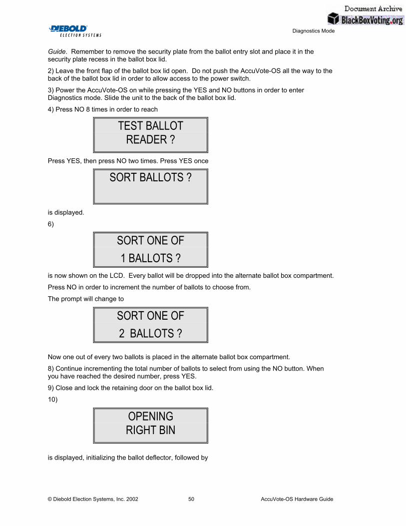
Diagnostics Mode
© Diebold Election Systems, Inc. 2002 AccuVote-OS Hardware Guide 50
Guide. Remember to remove the security plate from the ballot entry slot and place it in the security plate recess in the ballot box lid.
2) Leave the front flap of the ballot box lid open. Do not push the AccuVote-OS all the way to the back of the ballot box lid in order to allow access to the power switch.
3) Power the AccuVote-OS on while pressing the YES and NO buttons in order to enter Diagnostics mode. Slide the unit to the back of the ballot box lid.
4) Press NO 8 times in order to reach
Press YES, then press NO two times. Press YES once
is displayed.
6)
is now shown on the LCD. Every ballot will be dropped into the alternate ballot box compartment.
Press NO in order to increment the number of ballots to choose from.
The prompt will change to
Now one out of every two ballots is placed in the alternate ballot box compartment.
8) Continue incrementing the total number of ballots to select from using the NO button. When you have reached the desired number, press YES.
9) Close and lock the retaining door on the ballot box lid.
10)
is displayed, initializing the ballot deflector, followed by
TEST BALLOT READER ?
SORT BALLOTS ?
SORT ONE OF 1 BALLOTS ?
SORT ONE OF 2 BALLOTS ?
OPENING RIGHT BIN

Diagnostics Mode
© Diebold Election Systems, Inc. 2002 AccuVote-OS Hardware Guide 51
Feed the test deck of ballots into the AccuVote-OS. Note that the total sort amount includes ballots unsuccessfully read.
The number of ballots scanned is recorded in the following LCD message:
In this example, 10 ballots have been read and no ballots have been fed into the unit that have not been read. The symbol in the bottom left hand corner of the LCD indicates that ballots are being separated in the ballot box.
11) Unlock and open the retaining door once you have finished reading ballots. Press NO in order to terminate ballot counting on the AccuVote-OS.
12) If the ballot box being used has a back door, open the door and remove ballots from both compartments. If you are not using a ballot box with a rear door, close and lock the retaining door and unlock and open the ballot box lid, supporting the lid with the lift arm. Carefully remove ballots from both compartments, then close and lock the ballot box lid.
The number of ballots in the main compartment should compare with the number of ballots in the alternate compartment according to the specified factor.
13) If you wish to repeat the test for a different selection amount, repeat this procedure starting with step 4.
5.1.23. Reader Diagnostics Test report The Reader Diagnostics Test report provides a summary of voting positions marked on ballots on the idler and driver sides of the ballot reader for all ballots read in the Reader Diagnostics Test. The report includes:
• time
• date
• card length, in rows
• number of cards read in the test
• number of cards not processed
• number of ballots with an odd-length (an odd number of rows)
• number of voting positions with long marks
• number of voting positions with undefined marks
The body of the report lists the percentage of voting positions marked on all ballots in each channel. These figures are separated for the idler and the driver sides of the ballot reader.
Note that the statistics printed are based on the total number of ballots tested. Each ballot pass is averaged with previous ballot passes to produce the percentages printed in the report.
INSERT BALLOT IN READER
CARDS READ: 10 NOT READ: 0

Diagnostics Mode
© Diebold Election Systems, Inc. 2002 AccuVote-OS Hardware Guide 52
The Reader Diagnostics Test report is based on 8 channel readings only if you are using the AccuFeed — channels 1, 8, 9, 16, 17, 24, 25 and 32.
5.1.24. Printing the Reader Diagnostics Test report The Reader Diagnostics Test report is printed by pressing YES while the ballot is being scanned. The report is automatically printed when 500 ballots have been read. Not that the report is only valid for Diagnostic ballots.
appears on the LCD as the report is printed. Once the report has been printed, CARDS READ and NOT READ are reset to zero.
PRINTING READER TEST COUNTERS

Parts List
© Diebold Election Systems, Inc. 2002 AccuVote-OS Hardware Guide 53
6. Parts List
The Parts List provides the part numbers, part names and a brief description of parts. Be sure to have this information handy when ordering replacement parts.
6.1. AccuVote-OS unit parts list Part # Part Name and Description
312-2112 Modem Upgrade Kit This kit includes the modem, the modem power and serial cables, a new I/O Bracket with the phone and line jacks, deflector cable and main serial cable already attached. This kit also includes the modem mounting hardware.
411-2716 CPU Board Assembly (board with metalwork) Replacement mother board, fully populated except for the LCD and the printer. The Printer/LCD Mounting Bracket and Memory Card Cover are included. This part does not include the CPU board mounting hardware (453-1111).
411-3716 CPU Board Assembly (complete) Replacement mother board, fully populated including the LCD, the printer, and the metalwork. This part does not include the CPU board mounting hardware (453-1111).
421-2332 Power Supply Assembly
Replacement 120 volt AC switching power supply for the AccuVote-OS Unit. This part does not include the power supply mounting hardware (453-4111).
442-1111 Infra-red Reader Assembly
AccuVote-OS reader fully assembled including the reader motor. The mounting screws (453-2111) and reader interface cable (541-2311) are not included.
442-5111 Visible Light Reader Assembly
AccuVote-OS reader fully assembled including the reader motor. The mounting screws (453-2111) and reader interface cable (541-2311) are not included.
450-1111 Enclosure Assembly
Accu-Vote enclosure assembly including the memory card security plate and the label set. It does not include serial number label. The mounting screws (453-4111) for the internal components are not included.
452-1111 Internal I/O Cables Assembly (non-modem unit) Serial and deflector internal cables attached to an I/O bracket. This part does not include the I/O bracket mounting hardware (453-4111).
452-2111 Internal I/O Cables Assembly (modem unit)

Parts List
© Diebold Election Systems, Inc. 2002 AccuVote-OS Hardware Guide 54
Serial cable, deflector internal cable, and modem cables attached to an I/O bracket. This part does not include the I/O bracket mounting hardware (453-4111).
453-1111 CPU Board Mounting Hardware Kit This kit consists of screws, standoffs, washers and nuts required for mounting the CPU board to the AccuVote-OS enclosure.
453-2111 Reader Mounting Hardware Kit This kit consists of screws required for mounting the reader to the AccuVote-OS enclosure.
453-3111 Printer/LCD Mounting Hardware Kit This kit consists of screws required for mounting the printer and LCD to the printer/LCD bracket.
453-4111 Enclosure Mounting Hardware Kit This kit consists of screws required for mounting the power supply, paper roll holder, and I/O bracket to the AccuVote-OS enclosure. It also includes the screws required to attach together the AccuVote-OS enclosure’s lid and chassis.
453-4121 Memory Card Security Plate Mounting Hardware Kit This kit consists of screws and Ny-lok nuts required to mount the memory card security plate to the AccuVote-OS enclosure.
454-2111 Paper Roll Assembly
This assembly consists of the paper roll holder and paper roll shaft. This part does not include the mounting hardware (453-3111).
461-1111 LCD Assembly
LCD module with right angle connector. This part does not include the mounting hardware (453-3111).
471-1111 Printer Assembly
The internal printer mechanism with fifteen-conductor ribbon cable attached. Mounting screws not included. This part does not include the mounting hardware (453-3111).
510-1112 Internal Modem
This is the internal 2400 baud pocket modem that is installed into the AccuVote-OS. The mounting hardware is included with this part. There are no cables included.
512-4111 32K x 8 RAM IC
32Kb Static RAM chip.
512-4131 128K x 8 RAM IC
128KB Static RAM chip.
521-2111 Memory Card Security Plate
This part mounts onto the AccuVote-OS’s enclosure. It limits access to the memory card after it has been inserted. This part does not include the mounting hardware (453-4121).
541-0111 Loopback Connector

Parts List
© Diebold Election Systems, Inc. 2002 AccuVote-OS Hardware Guide 55
This connector is used for testing the main serial port of the AccuVote-OS unit.
541-1111 Internal Modem Power Cable (2400) This is the special cable that powers the modem from a connection on the CPU board.
541-1121 Internal Modem Power Cable (1440) This is the special cable that powers the modem from a connection on the CPU board.
541-2211 LCD Interface Cable
This fourteen-conductor ribbon cable connects the LCD to the CPU board.
541-2311 Reader Interface Cable
This twenty-conductor ribbon cable connects the reader to the CPU board.
621-3311 Diagnostic Test Ballot Cards (Type 3) A package of twenty-five special cards for use in testing whether the Accu-Vote unit is reading all of the potential voting positions on the ballot cards.
621-6111 Demonstration Test Ballot Cards
A package of twenty-five demonstration ballots for use in testing whether the Accu-Vote unit is reading marks on ballot cards during a test election. These ballots can be used with a test memory card (641-2111) loaded with the demonstration ballot card data.
641-2111 Test Memory Card
A memory card containing pre-loaded data that is recognizable by the Accu-Vote ballot processing unit. This memory card is used to test whether or not a problem exists in a test election mode using the demonstration test ballot cards (621-6111)
721-1111 ROM Set (64K x 8) 64KB EPROM chip(s). This chip(s) would be programmed with the firmware.
6.2. Ballot box unit parts list Part # Part Name and Description 445-1111 Deflector Motor Mounting Hardware Kit This motor moves the ballot deflector. This part has a cabling harness
attached to it which connects to the ballot box cable. This part does not include the mounting hardware (453-7111).
453-7111 Deflector Motor Mounting Hardware Kit This kit consists of screws for mounting the ballot box deflector motor to the motor mount bracket and two plastic tie straps for anchoring the slack cable.
453-7121 Ballot Box Cable Mounting Hardware Kit

Parts List
© Diebold Election Systems, Inc. 2002 AccuVote-OS Hardware Guide 56
This kit consists of screws, nuts, and plastic tie straps required for mounting the ballot box cable.
533-2113 Deflector A gate inside the ballot box, which may be used to deflect either blank ballots or ballots containing write-in votes into a separate compartment in the ballot box. This component includes the motor coupler and set screws.
542-1121 Ballot Box Cable
This cable has the ballot box deflector connector and bracket on one end and the ballot box motor interface connector on the other end. This part does not include the mounting hardware (453-7121).

Unit Specifications
© Diebold Election Systems, Inc. 2002 AccuVote-OS Hardware Guide 57
7. Unit Specifications
This chapter covers the mechanical and electrical specifications of the AccuVote-OS ballot processing unit.
7.1. Mechanical Size: 16" x 14" x 3"
Weight: 15 lbs.
7.2. Electrical Power Supply Input: 120 VAC, 60/50 Hz @ 0.3 A
Power Supply Output Capacity: 14.8 volts DC @ 2.5 A
5.0 volts DC @ 1.0 A
Operating Current: 0.3 A nominal @ 14VDC (idle)
2.4 A peak @ 14VDC (printing)
Deflector Motor Current: 0.3 A nominal @ 14 VDC
7.2.1. Communications Modulation: RS-232C
Protocol: XON/XOFF
Baud Rate: 9, 600
Data Bits: 8
Parity: None
Stop Bits: 1
Pin Definition: See Appendix B
7.2.2. External connections Power Input: 120 VAC, 50/60 Hz,
suitable for Belden 17250 cable
Communications: DB9-M 9-pin plug (DTE)
7.2.3. Operating environment
Temperature: +40° F to +100° F
+5° C to +38° C
Humidity: 30% to 90% non-condensing
Vibration: 0.25 G

Unit Specifications
© Diebold Election Systems, Inc. 2002 AccuVote-OS Hardware Guide 58
7.2.4. Storage environment Temperature: +5E F to +104E F
-15E C to +40E C
Humidity: 5% to 95% non-condensing
Vibration: 2.0 G
7.2.5. Transportation environment Temperature: +5E F to +122E F
-15E C to +50E C
Humidity: 5% to 95% non-condensing
Vibration: 2.0 G
7.2.6. Ballot cards Length: 11, 14, 18 in. (+ 0.060 in. - 0.000 in.)
Width: 8.50 in. (+ 0.030 in. - 0.020 in.)
Thickness: 7 point (0.0070 in. to 0.0085 in. ± 0.0005 in.)
Weight: Nominal 90 lb. Index stock
For more information on ballot cards, see the document entitled AccuVote-OS Ballot Specifications
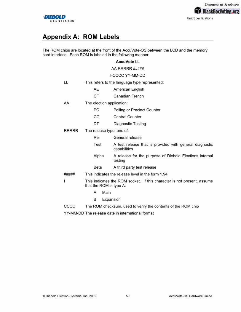
Unit Specifications
© Diebold Election Systems, Inc. 2002 AccuVote-OS Hardware Guide 59
Appendix A: ROM Labels
The ROM chips are located at the front of the AccuVote-OS between the LCD and the memory card interface. Each ROM is labeled in the following manner:
AccuVote LL
AA RRRRR #####
I-CCCC YY-MM-DD
LL This refers to the language type represented:
AE American English
CF Canadian French
AA The election application:
PC Polling or Precinct Counter
CC Central Counter
DT Diagnostic Testing
RRRRR The release type, one of:
Rel General release
Test A test release that is provided with general diagnostic capabilities
Alpha A release for the purpose of Diebold Elections internal testing
Beta A third party test release
##### This indicates the release level in the form 1.94
I This indicates the ROM socket. If this character is not present, assume that the ROM is type A.
A Main
B Expansion
CCCC The ROM checksum, used to verify the contents of the ROM chip
YY-MM-DD The release date in international format

Unit Specifications
© Diebold Election Systems, Inc. 2002 AccuVote-OS Hardware Guide 60
Appendix B: RS-232 Pin Definitions
The following table defines the signals and corresponding pins on the rear DB9-M serial connector which is wired as a DTE. This table represents a complete definition of all the pin assignments for the connector.
Note that not all of these pins are used by the AccuVote-OS ballot processing unit.
DB9-M
PIN NO.
SIGNAL NAME
SIGNAL
FUNCTION
SIGNAL
DIRECTION
USED BY
ACCUVOTE-OS?
1
DCD
Data Carrier Detect
From Host
N
2
RXD
Receive Data
From Host
Y
3
TXD
Transmit Data
To Host
Y
4
DTR
Data Terminal Ready
To Host
N
5
GND
Signal Ground
Both
Y
6
DSR
Data Set Ready
From Host
N
7
RTS
Request to Send
To Host
N
8
CTS
Clear to Send
From Host
N
9
RI
Ring Indicator
From Host
N

Unit Specifications
© Diebold Election Systems, Inc. 2002 AccuVote-OS Hardware Guide 61
Adapter cable The following table defines the signals and corresponding pins on the DB9-F to DB25-M external adapter cable (Diebold PN 192-1121):
SIGNAL NAME
SIGNAL
FUNCTION
DB9-F
PIN NO.
DB25-M
PIN NO.
DCD
Data Carrier Detect
1
8
RXD
Receive Data
2
3
TXD
Transmit Data
3
2
DTR
Data Terminal Ready
4
20
GND
Signal Ground
5
7
DSR
Data Set Ready
6
6
RTS
Request to Send
7
4
CTS
Clear to Send
8
5
RI
Ring Indicator
9
22

Unit Specifications
© Diebold Election Systems, Inc. 2002 AccuVote-OS Hardware Guide 62
Appendix C: Definitions
Listed below are definitions for some of the more technical terms included in this manual. They appear in alphabetical order.
Absentee Count card A special card that when inserted in the AccuVote-OS unit, signals the unit to
begin reading absentee ballots. Any ballot inserted after this card will be read as an absentee ballot.
AccuVote-OS ballot processing unit A unit, the size of a laptop computer, that uses mark-sense technology to read both sides of a ballot simultaneously. All ballot information is stored on a removable, 32Kb, 64Kb, or 128Kb memory card.
ACK code Shortened form of Acknowledge Character.
Audit Report A record of the processes performed, and/or the changes made to the system's data.
Ballot Box The sealed box used to secure voted ballots and carry them from the precinct
to the central vote counter. This box is also used to house the AccuVote-OS ballot processing unit during the ballot-counting process.
Ballot Card A single piece of paper on which is printed race and candidate information for the voters to vote on. Each ballot type is made up of one or more physical ballot cards.
Ballot Deflector A gate located inside the ballot box, which is activated by the AccuVote-OS
ballot processing unit. When signalled, the deflector moves to direct the ballot into the appropriate storage slot within the ballot box.
Blank Voting Blank voting is when a voter does not vote for any candidates in the race.
Card Identification Marks These are small black boxes that appear along the width of the ballot card opposite the diagnostic marks on both the front and back of the ballot card.
The ID marks identify the card sequence, card number, precinct number, ender mark, election type and election date.
CPU (Central Processing Unit) The part of a computer where commands are received, decoded, and carried out. Every computer has a CPU.
Delimiter A special character used to separate parts of data such as strings of characters.

Unit Specifications
© Diebold Election Systems, Inc. 2002 AccuVote-OS Hardware Guide 63
Diagnostic marks The small black boxes set at regular intervals across the width of both the top front and top back of the printed ballot card.
Download To transfer data from the central computer down to the AccuVote-OS memory cards.
Downloaded Text Text in the Precinct Summary Total that can be customized to meet your jurisdiction's requirements.
Ender Card A special card that when inserted in the AccuVote-OS ballot processing unit, signals the end of the election. The AccuVote-OS unit responds by printing a Totals Report, and electronically locking the ballot reader to prevent further ballot processing.
Host Computer A large, central computer to which the AccuVote-OS ballot processing unit is connected.
Interface The liaison between the computer and the user, by way of handling information in different formats.
Landscape Landscape is a horizontal orientation in which the long end of the card is the top, and the narrow ends are the sides.
LCD (Liquid Crystal Display) An alphanumeric display, like that on a digital clock. A liquid crystal is sealed between polarizers and glass, and when activated by external light, it forms characters.
LF code Shortened form of Line Feed.
Loop A sequence of program commands that are executed repeatedly.
Mark-Sensing The reading of (voting) marks by way of scanning with an optical scanner.
Memory card A small card used in the AccuVote-OS ballot processing unit to store precinct information and to record ballot results.
Override To force the AccuVote-OS unit to accept a rejected ballot card, such as an
overvoted card, by pressing the YES button while the card is being read.
Overvoting Overvoting is when a voter votes for more candidates than he/she is eligible to vote for in a race.

Unit Specifications
© Diebold Election Systems, Inc. 2002 AccuVote-OS Hardware Guide 64
Port The connector on a host computer where a terminal (printer, AccuVote-OS unit, or other such device) is connected, and by means of which information can be transferred.
Portrait Portrait is a vertical orientation in which the narrow end of the card is the top, and the long ends are the sides.
Protocol A set of parameters governing the communication and transfer of information between the host computer and the AccuVote-OS ballot processing unit.
RAM (Random Access Memory) A type of memory that can be accessed directly without having to follow a particular path of storage locations.
ROM (Read-Only Memory) A type of memory chip that can be read but cannot be written on or altered.
RTS code An abbreviation for Request to Send.
Test Cards
Two test cards are available for testing the AccuVote-OS unit. The marked test card test that the ballot reader is reading all the marks that it should. The blank test card tests that the ballot reader isn't reading extraneous marks.
Timing Marks
Small black boxes set at regular intervals down the outside edges of the length of the printed ballot card. All voting boxes that are printed on the ballot must be aligned with the timing marks (and the diagnostic marks) so that the AccuVote-OS ballot processing unit can recognize each race and candidate for ballot-counting.
Totals Report The Totals Report lists all the vote counts currently recorded for the present election. Depending on when it is printed, the Totals Report can have any of seven titles: Zero Totals Report, Test Zero Totals Report, Test Results Report, Test Totals Report, Election Zero Totals Report, Election Results Report, or Election Totals Report.
Undervoting Undervoting is when the voter votes for fewer candidates than he/she is eligible to vote for in a race.
Upload To transfer data from the AccuVote-OS memory cards up to the central computer.
Voting mark The mark on the ballot created by a voter selecting his preferred candidate.

Unit Specifications
© Diebold Election Systems, Inc. 2002 AccuVote-OS Hardware Guide 65
Workstation A computer monitor and keyboard, with associated software, which has a direct line of communication with the central computer.
Write-Ins Write-ins are the blank lines on the ballot where the voter writes the name of a candidate that was not nominated to run in this race.