acd 10,1c4 - nasa · acd 10,1c4 contractor: ... scc t ion page foreword ... testing has been...
TRANSCRIPT
ACD 10,1C4
Contractor:
ROLLER-GEAR DRIVE DEVELOPMENT
February 1971
FINAL REPORT Contract No. NAS8-26213
General Electric Company Avionic Controls Department P.OoBox 5000 Binghamton, New York 13902
Contracting Officer : National Aeronautics and Space Administration Marshall Space Flight Center Huntsville, Alabama
Prepared by: Ro Bo Serninski Go F, Auclair
w - - -- 2 (E?
https://ntrs.nasa.gov/search.jsp?R=19710010387 2018-07-28T22:55:07+00:00Z
TABLE OF CONTENTS
Scc t ion Page
FOREWORD ................................. 1 INTRODUCTION AND SUMMARY ...................
Introduction ............................... Suniniary ................................
2 TECHNICAL DISCUSSION OF ROLLER-GEAR DRIVE ...... Overview and Theory of Operation ................ Roller-Gear Drive Description .................. Manufacturing and Design Modifications ............ Design Requirements ........................
3 ROLLER-GEAR DRIVE EVALUATION . . . . . . Unitweight ............................... Motor Back EMF grid Alignment ................. Breakaway Friction ......................... Running Friction ........................... Backlash and Torsional Stiffness ................. Output Torque versus Input Command ............. Roller-Gear Transmission Efficiency .............
4 CONCLUSIONS AND RECOMMENDATIONS ............. Conclusions .............................. Recommendations ...........................
DEFINITION OF TERMS ......................... APPENDM A . DRAWING STRUCTURE ............... REFERENCES ................................
iii
1
1 1
5
5 8
10 13
15
15 16 16 16 18 18 21
26
26 26
27
28
29
i
LIST OF ILLUSTRATIONS
Figure
1
2
3
4
5
6
7
8
9
Roller-Gear Drive ............................. Basic Roller-Gear Drive Concept ................... Roller.Gears ................................. Roller-Gear Drive Design ........................ Measured Roller-Gear . Gear Running Friction .......... Measured Roller-Gear Drive Output ................. Measured Roller-Gear Drive Loaded Friction ........... Measured Roller-Gear Transmission Efficiency .........
Measured Transmission Torque . Rotational Deflection . . . .
Page
2
6
7 11
17
19
20 24
25
ii
FOREWORD
This report was prepared by the General Electric Company's Avionic Controls De- partment, Binghamton, New York, on Contract NAS8-26213 administered under the
direction of the National Aeronautics and Space Administration, Marshall Space Flight Center.
This is the final report for this contract and covers the work performed on Change Order No. 1, namely the design, fabrication and test of a roller-gear drive "test fixture". This work WBS performed during the period of October 1970 through February 1971. An earlier interim report was issued which covered the design, fabrication and testing of two 5 ft-lb brushless dc motors developed on this contract during the period of June 1970 through November 1970.
The development of the roller-gear drive was a group effort. Dr. A. L. Nasvytis, inventer of the roller-gear concept, providee consultation service to General Electric and furnished the fundamental design and related analyses. The principle General Electric contributors were: R. B. Seminski, Project Engineer, who provided the
overall mechanical layout and design; J. B. Robinson, Drafting Designer; and P. S.
Schriebmaier, Assembly and Test. The Program Manager was G. F. Auclair.
iii

Section 1
INTRODUCTION AND SUMMARY
INTRODUCTION
This report summarizes the work performed on contract NAS8-26213 through February 19, 1971. This report mainly covers the design, fabrication, and test of a research model roller-gear drive assembly whic; mission driben by a n integrally mounted brushless dc motor. The development of the brushless dc motor was described in an earlier interim report on this contract (Reference 1).
msists of a roller-gear trans-
The roller-gear drive was chosen for development because of its potential usefulness in a wide range of applications, both as power drives and as precision servo drives. The advantages of the roller-gear transmission, compared to conventional gear trans- missions, is summarized in Table 1.
SUMMARY
The roller-gear drive developed on this contract has demonstrated the basic per- formance capability of the roller-gear transmission approach. Although only limited testing has been conducted to date, the drive compactness, low weight and high ef- f iciency have been demonstrated.
Figure 1 shows photographs of the roller-gear drive. Table 2 summarizes the as- sembly characteristics in the mode I power drive configuration (no rol lers on output ring gear).
Further development of the roller-gear drive is desirable. Complete testing of the
present unit in both the mode I power drive configuration and the mode II servo drive configuration should be performed. Design, fabrication and test of several units for specific applications is required to fully evaluate the effectiveness and applicability of the roller-gear drive.
1
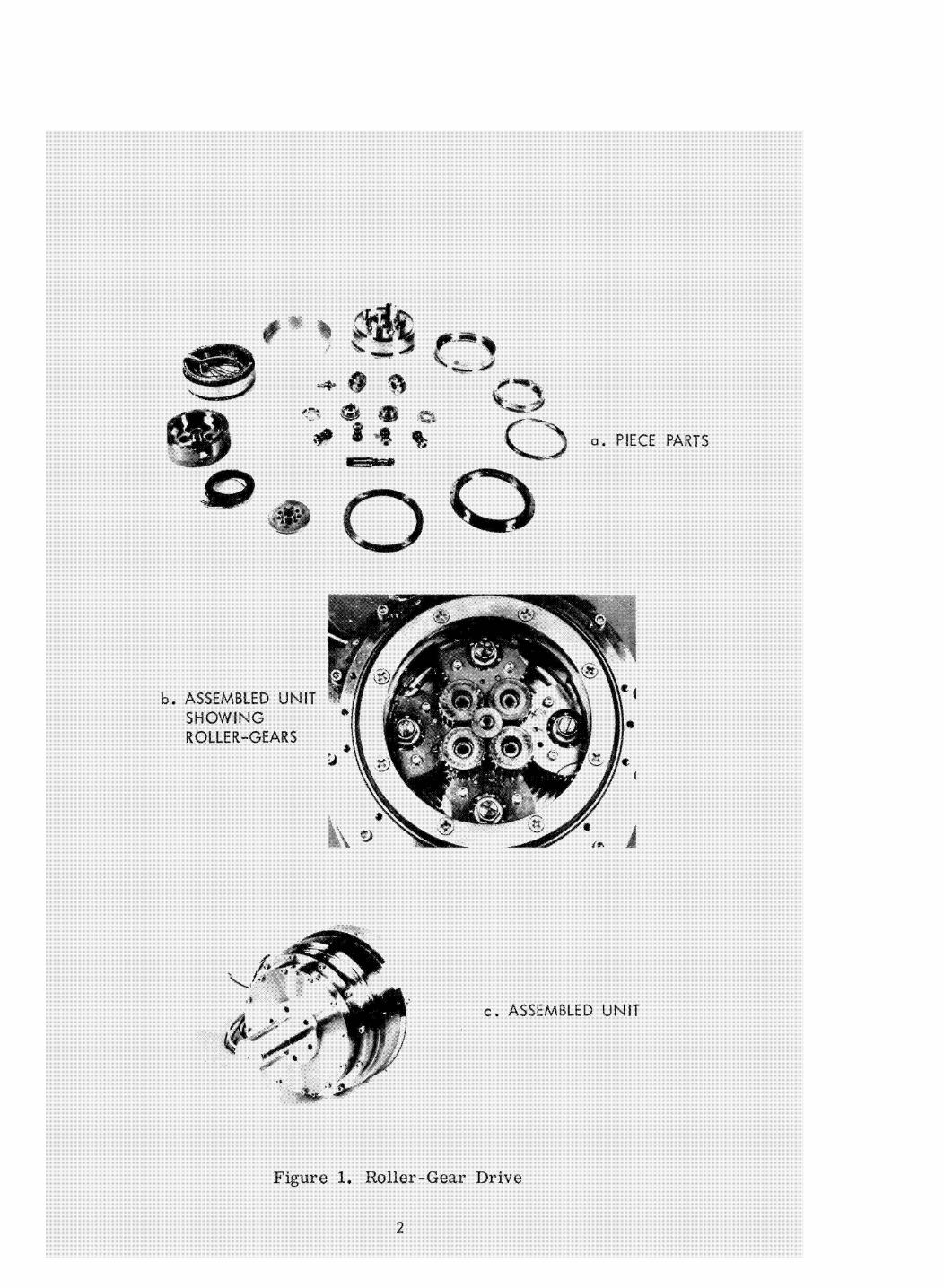
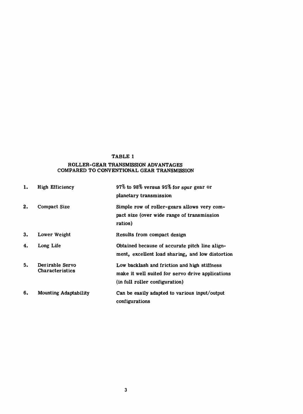
TABLE 1
ROLLER-GEAR TRANSMISSION ADVANTAGES COMPARED TO CONVENTIONAL GEAR TRANSMISSION
1. High Efficiency
2. Compact Size
97% to 98% versus 95% for spur gear or planetary transmiss ion
Simple row of roller-gears allows very com- pact size (over wide range of transmission ratios)
3. Lower Weight Results from compact design
4. Long Life
5. Desirable Servo Characteristics
Obtained because of accurate pitch line align- ment, excellent load sharing, and low distortion
Low backlash and friction and high stiffness make it well suited for servo drive applications (in full roller configuration)
6. Mounting Adaptability Can be easily adapted to various input/output configurations
3

TABLE 2
ROLLER-G EAR DRIVE CHARACTERISTICS
Rated Output Torque Gear Ratio Weight - gears
- case - motor
Total Size Transmission Efficiency Breakaway Friction (output) Backlash* Torsional Stiffness Design Life (90% reliability)
78
15.125
2 . 8
4 . 4
6 .6
13.8
6.5 Dia x 4.4
97.7
0.2
3.2
48,000
> 10,000
* Note 1 - in mode I operation, no rol lers on output ring gear
ft-lb -- lbs
lbs lbs lbs inches percent ft-lb
arc minutes f t - lb/r adian hours
- with full roller configuration (mode II), near zero backlash is expected
Note 2 - see reference 1 for characteristics of brushless dc motor
4

Section 2
TECHNICAL DISCUSSION OF ROT LER-GEAR DRIVE
OVERVIEW AND THEORY OF OPERATION
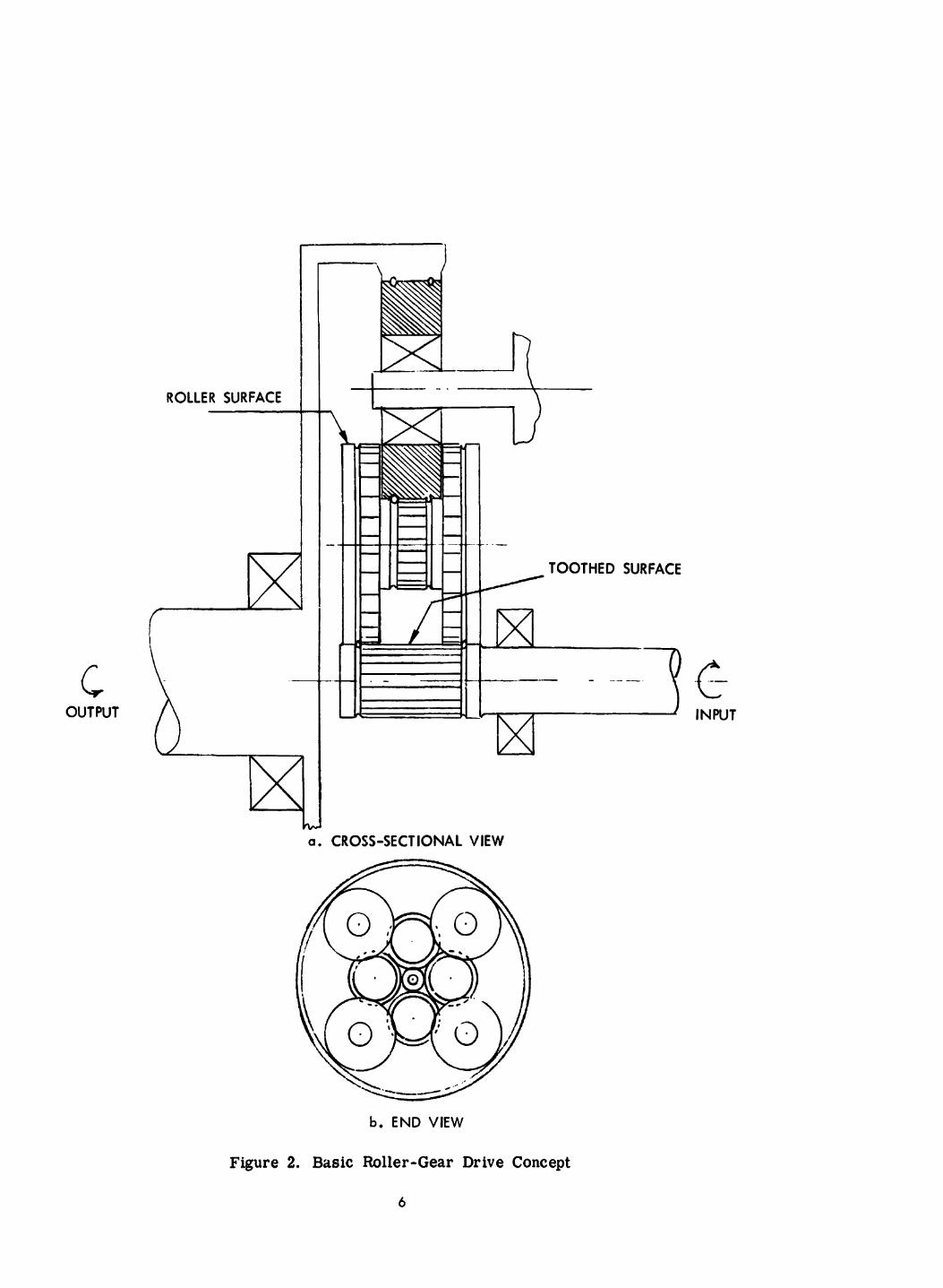
The roller-gear transmission concept evoived from work performed at TRW, Accessories Division, Cleveland, Ohio, in the mid-l960’s, and is mairl’y the product of ideas conceived by Dr. A. L. Nasvytis, who P e n worked for TRW (see references 2 and 3). The roller-gear approach evolved from the roller-friction drive, and basically consists of a roller-friction drive with gears mounted on all rolling contacts. The basic roller-gear concept is illustrated in Figure 2. The roller-gear elements fabricated on this contract are shown in Figure 3.
The roller-gear drive retains many of the advantages of the roller-friction drive while eliminating the high preload requirements of the roller-friction drive. In ef-
fect, the gears now transmit the high torque loads while the rollers act as integral bearings supporting the gears, transmitting low torque loads, and overall, providing stable gear alignment and resultant high efficiency.
Basically, the drive employs the planetary principk, i. e., sun planet a d ring gear arrangement. By combining the pure roller drive concept with planetary gears, more than one planet row can be employed thus increasing the torque capability of the simple planetary drive.
The additional planet components permit sharing the load of each gear element at more than one contact point for a greater utilization of the teeth at any respective gear. This results in a greater packaging density with lower size and weight.
In theory, the rollers act as bearings to guide and define the rotational path of the gear elements. The resultant friction drive torque of 10 to 25% is a secondary effect inherent in this design approach. Each gear possesses rollers with a rolling diameter equal to the operating pitch diameter of the gears.
5
c
ROLLER SURFACE
\. OUTPUT
a. CROSS-SECTIONAL VIEW
b. END VIEW
Figure 2. Basic Roller-Gear Drive Concept
6


In comparison to a conventional spin gear or planetary transmission, the roller-gear drive renders advantages summarl; t earlier in Table 1 due to the following:
U
I
I
m
Smaller elements Efficient suppart system Hlgfi reduction ratio capability Less weight Longer Me Parallel zlignment due to roller contact on pitch line High efficiency &e t3 near perfect t0~t.h contact and lower total number of contacts Good load distribution Low vibration
Several rollei -gear drives have been built. and evaluated in power drive applications, mainly for helicopter drives, with excellent results (references 2 and 3). These have been in the 500 horsepower, 50,000 rpm (input) range. Currently, five units are being fabricated by Sikorsky Aircraft for evaluation on their helicopters.
Roller-gear drives appear well suited for servo drive applications as well as power drive applications, As a servo drive, it potentially has the desirable characteristics of low backlash, low Iriction, and high stiffness. To date, however,there has been no known effort to develop and evaluate a roller-gear drive unit for servo applications.
DESIGN REQUIREMENTS
Table 3 lists the design requirements that were defined as design goals by General Electric for the roller-gear tra!!mission.
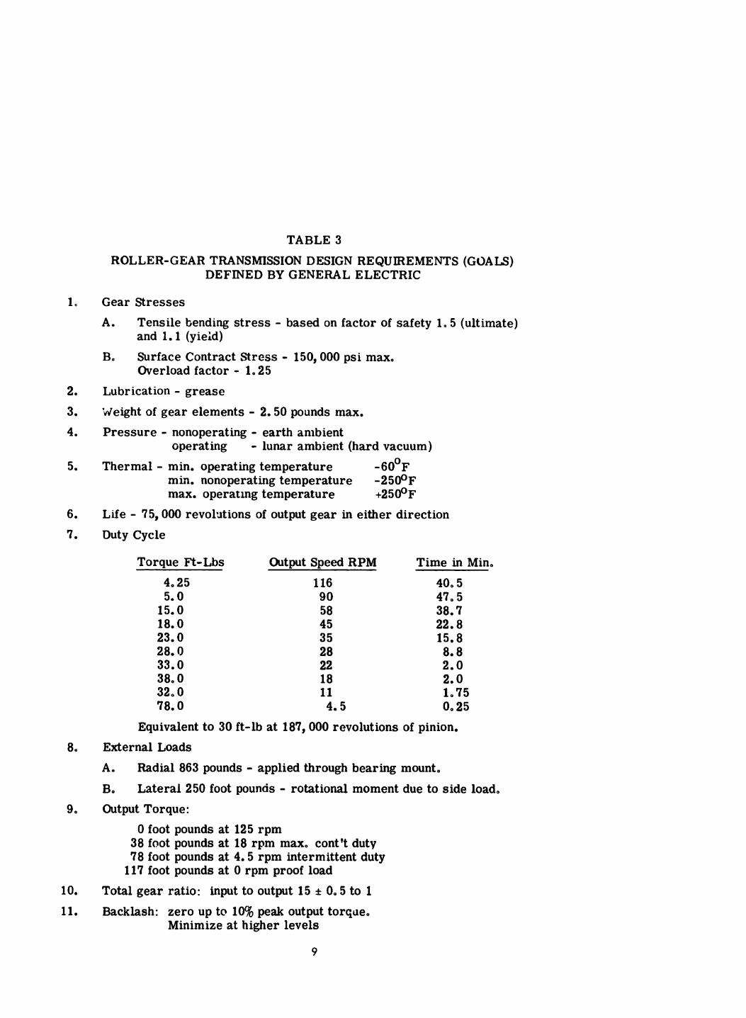
TABLE 3
ROLLER-GEAR TRANSMISSION DESIGN REQUIREMENTS (GOALS) DEFINED BY GENERAL ELECTRIC
1.
2. 3. 4.
60
80
90
10. 11.
Gear Stresses A.
B.
Tensile bending stress - based on factor of safety 1.5 (ultimate) and 1.1 (yieid) Surface Contract Stress - 150,000 psi max. Overload factor - 1.25
Lubrication - grease 'deight of gear elements - 2.50 pounds max. Pressure - nonoperating - earth anibient
Thermal - min. operating temperature operating
min. nonoperating temperature -250°F max. operatmg temperature +250°F
- lunar ambient (hard vacuum) -60°F
Life - 75,000 revohtions of output gear in either direction Duty Cycle
Torque Ft-Lbs 4,25 5.0 15.0 18.0 23.0 28.0 33.0 38,O 32.0 78.0
Output Speed RPM 116 90 58 45 35 28 22 18 11 4. 5
Time in Min. 40,s 47.5 38.7 22.8 15.8 80 8 2.0 2.0 1,75 0.25
Equivalent to 30 ft-lb at 187,000 revolutions of pinion. External Loads A,
Be Output Torque:
Radial 863 pounds - applied through bearing mount. Lateral 250 foot pounds - rotational moment due to side load,
0 foot pounds at 125 rpm 38 foot pounds at 18 rpm max. cont't duty 78 foot pounds at 4.5 rpm intermittent duty 117 foot pounds at 0 rpm proof load
Total gear ratio: input to output 15 f 0.5 to 1 Backlash: zero up to 10% peak output torque.
Minimize at higher levels
9
The unit was to have performance and interface requirements that would make it su i t -
able for use in the wheel drive assembly in a Ltlnar Roving Vehicle. At the same time, this program was considered as an advanced technology type where the concepts developed would be us able in other applications. Hence, the roller-gear assembly was designed ta allow its evaluation also as a servo drive unit, such as the control moment gyro (CMG) gimbal drive unit.
ROLLER-GEAR DRIVE DESCRIPTIilN
Figure 4 illustrates the configuration employed for th js roller-gear drive application. Pinion w w a drives gear vxlw (xl/yl planet assembly) which is on a common shaft
with gear "y The gear "ylW drives "x It which in turn drives the ring gear C. 1 ' 2 Gears "x2" have fixed center of rotation defined by ball bearings mounted on canti- levered shafts connected to the main housing.
The drive assembly is divided into two main parts consisting of the motor and trans- mission which are separated by a vertical plate which forms the main structural element cf the housing. Extensions from this plate provide mounting for the torquer stator, Hall resolver stator, and transmission bearkgs.
Four cantilevered stub shafts with duplex bearings pick up the second row planets so that the reaction torque of the transmission can be transferred to the fixed frame. The output bearings are mouirted on an extension of the main housing to place the output of the transmission on the opposite side of the input.
Large diameter duplex torque tube bearings are employed to resist moment and thrust loads produced at the wheel of the vehicle. This bearing installation is s imilar to that presently employed with the General Motor spur gear drive for the Lunar Roving Vehicle.
A cantilevered sun gear shaf t supports the torquer rotors with the gear rol lers pro- viding the bearing action,
10

8
II - 1
I 1 1
Precision gears are employed having a tooth-to-tooth composite tolerance of 0.0002 '' and a total composite tolerance of 0.0008". These are nitrided and ground from Nitralloy 135M material. Rollers of AlSl 52100 bearing steel are finish-ground after a shrink fit installation of the gears.
The transmission is lubricated with Anderol 79349 grease with a n initial light coating of Anderol 401D oil. This is a mace qualified lubrication system. However, other greases and oils could be employed if dictated by mission requirements.
Titanium is employed for the main housing providing an operating capability at 250°F miriimizing differential thermal expansion effects and weight.
The drive is designed to operate in two different modes; one a power application and the other a servo application.
MODE I - POWER APPLICATION, WHEEL DRIVE
The drive is primarily designed with performance and interface characteristics suitable for the wheel drive application on the Lunar Roving Vehicle. Rollers are re- quired to define the axes of rotation on only the sun and planet gears. The output ring gear is supported by the output bearings eliminating the need for an output roller and minimizing weight and complexity. This permits backlash in the ring gear meshes which is permissible.
Preload must be created to insure all planet and sun rol lers are in contwt. This is provided by placing the 2nd row planet ball bearing centers in a position to obtain a bearing radial load of 10 to 20 lbs. This is accomplished by making the bearing mounting diameters of the planet shafts 0.001 inch eccentric relative to the housing mounting diameter. Effectively the gear centers are adjusted at assembly through the cranking action supplied by the bearing shafts.
12
MODE II - SERVO APPLICATION, GIMBAL DRIVE
The roller-gear drive has also been designed with the capability of incorporating output rollers on each side of the output ring gear. Shrink rings are doweled to each side of the ring gear so that their rollmg surfaces mate with the 2nd row planet rollers with preload provided by an interference fit. This removes all backlash in the output torque range up to 20% of peak rated torque. When torque is applied during the transition stage from traction to gear drive, the displacement is a combination of creep, torsional wind-up and sliding action. This operating mode of the roller- gear drive wi l l allow evaluation of the unit for precision servo drive applications, such as a CMG gimbal drive.
Additional design details and calculations for the roller-gear transmission are given in references 4 and 5.
MANUFACTURING AND DESIGN MODIFICATIONS
As expected in an advanced technology development program such as this, several design modifications were defined during the assembly and test of the roller-gear drive unit. Two of these should be mentioned:
a. Input shaft bearing. A s can be seen in Figure 4a, the input shaft (to which the motor is mounted) is totally aligned by the rol lers on the roller- gear elements. It was originally plamed to inchde a bearing on the in- put shaft, but subsequent deslgn considerations indicated that it was not necessary.
During assembly of the roller-gear drive it was noted that the input shaft
radial stiffnesa was not sufficient to prevent the motor rotor from pulling to one side within the stator (due to magnetic forces) and consequently rubbing against the stator. Further design evaluation indicated that this could indeed occur with the desired roller-preload values, and that an input shaft bearing would greatly improve this stiffness and allow satis- factory performance.
13
Hence, in the present roller-gear drive, an input shaft bearing has been added on the outside of the motor (mounted to the transmission cover). In any future design, this bearing should be incorporated on the inside of
the motor (on the plate separating the motor and transmission compart- ments) to provide better design integrity and ease of assembly.
b. Roller-gear electron-beam welding. The manufacture of the first raw roller-gears required an electron-beam welding cycle. In the manufacture of the present roller-gears, some hairline cracks on the inside diameter of the roller-gears was noted after electron-beam welding. These cracks were in a low stress area and the roller-gears were deemed acceptable for use in this development model roller-gear drive (manufacture of new gears would have resulted in considerable schedule slippage). No effect on performance was expected or measured by the use of these gears, but it is possible that they could reduce the life of this roller-gear drive unit (because of fatigue failure) . Modified fabrication procedures have been defined to eliminate the occur- rence of cracks in future roller-gears. These include:
I Added base material in area of electron-beam weld
I Immediate stress-relief heat treat cjcle following electron- beam weld
I Better definition of optimum electron-beam welder settings (by several sample test runs).
14
Section 3 ROLLER-GEAR DRIVE EVALUATION
Limited evaluation tests of the roller-gear drive were performed prior to delivery to NASA. These consisted of functional tests to determine the basic drive parameters, and were performed in the mode I power drive configuration (no output ring gear) only. It is highly recommended that testing in the mode II servo drive configuration be performed at some future date.
The evaluation tests performed indicate the excellent characteristics achievable with the roller-gear drive. In particular, very low breakaway and running friction and
very high efficiency were obtained in this very compact and low welght assembly.
The following paragraphs briefly describe the tests performed and the resulcs. For tests requiring brushless dc motor drive electronics, the breadboard electronics developed on contract NAS8-25085 were employed.
UNIT WEIGHT
The measured roller-gear drive unit weight and weight breakdown is given in Table 4.
TABLE 4
MEASURED ROLLER-GEAR DRNE WEIGHT
Roller-gear elements (including bearings) 2.8 lbs
rn Brushless dc motor (with Hall resolver and 6.6 mounting hubs)
Unit housing 4 .4 - Total Weight (without output stub shaft used for testing) 13.8 lbs
15
MOTOR BACK EMF AND ALIGNMENT
After assembly of the roller-ge;r drive with the No. 1 brushless dc motor, the motor back-emf was checked to be nominal, and then the motor and Hall resolver aligned. (See reference 1 for brushless dc motor details.)
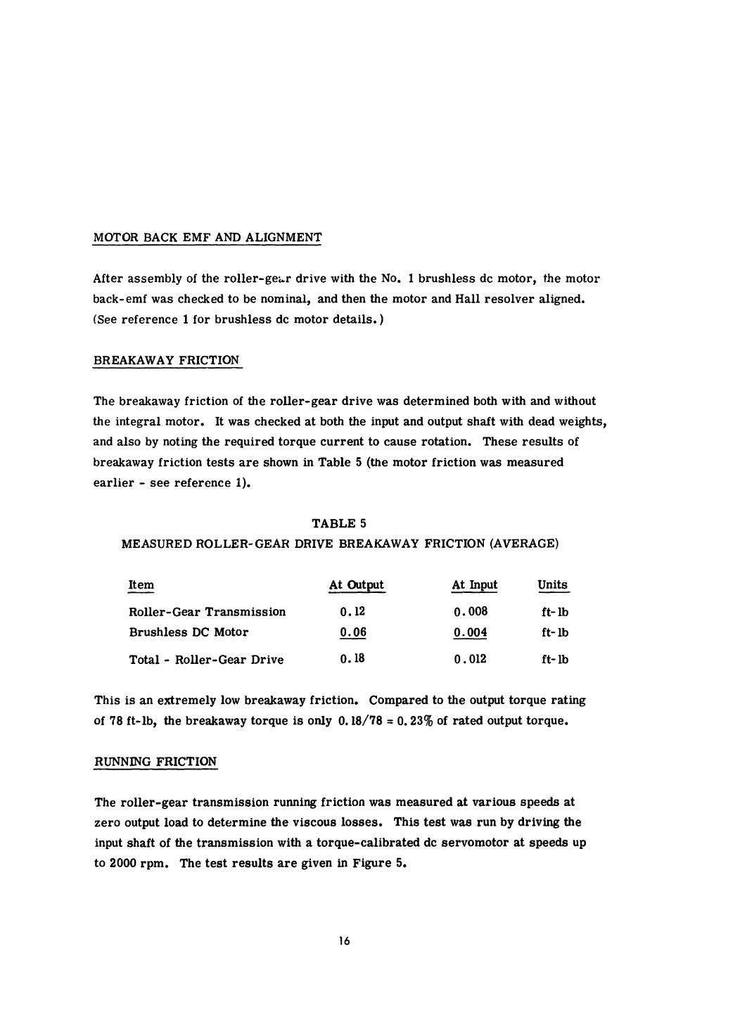
BREAKAWAY FRICTION
The breakaway friction of the roller-gear drive was determined both with and without the integral motor. It was checked at both the input and output shaft with dead weights, and also by noting the required torque current to cause rotation. These results of
breakaway friction tests are shown in Table 5 (the motor friction was measured earlier - see reference 1).
TABLE 5
MEASURED ROLLER- GEAR DRIVE BREAKAWAY FRICTION (AVERAGE)
It em At Output At Input Units - Roller- Gear Transmission 0.12 0.008 ft- lb Brushless DC Motor - 0.06 0.004 ft- lb
Total - Roller-Gear Drive 0.18 0.012 ft- lb
This is an extremely low breakaway friction. Compared to the output torque rating of 78 ft-lb, the breakaway torque is only 0.18/78 = 0.23% of rated output torque.
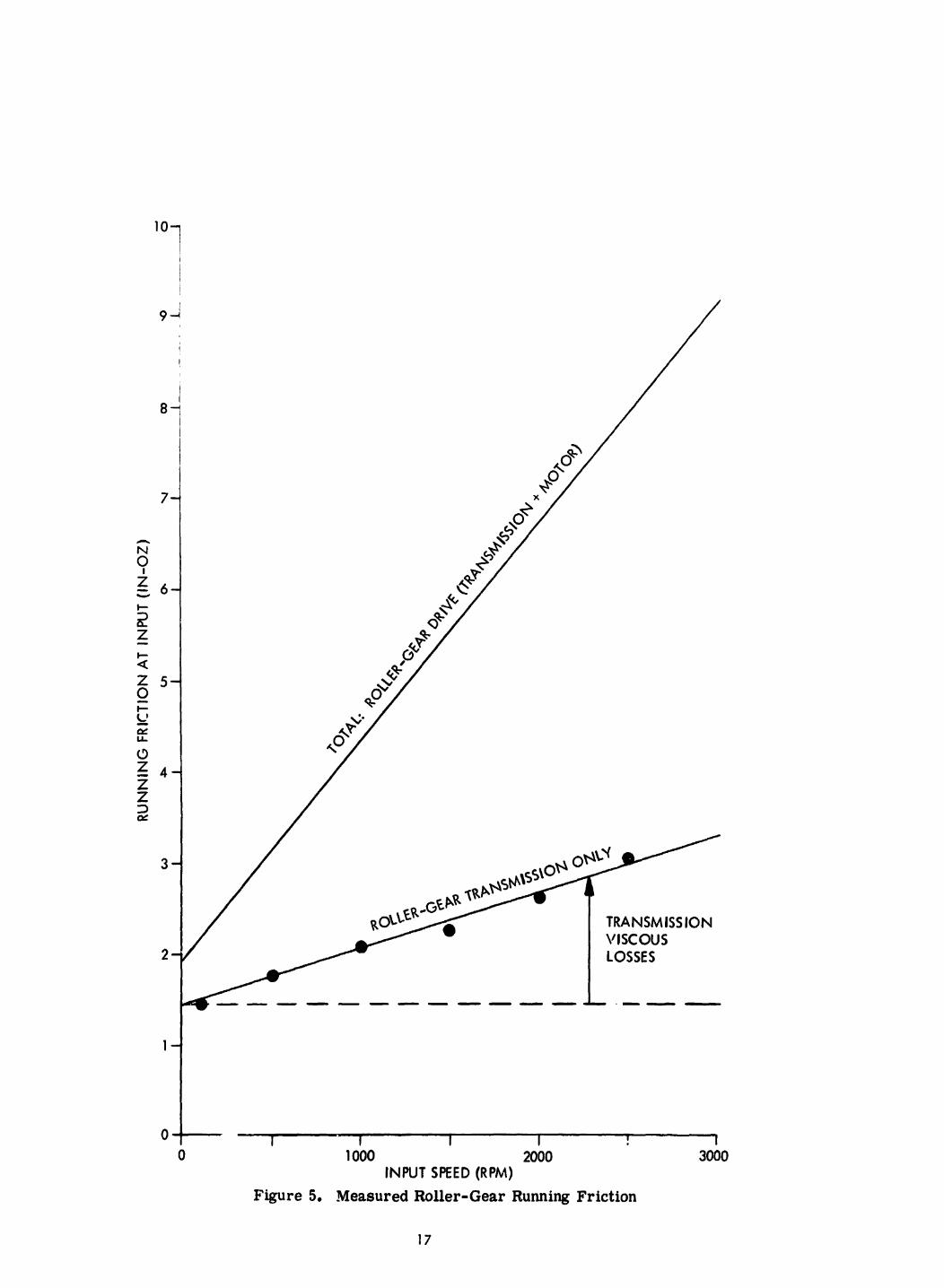
RUNNING FRICTION
The roller-gear transmission running friction was measured at various speeds at zero output load to determine the viscous losses. This test was run by driving the input shaft of the transmission with a torque-calibrated dc servomotor at speeds up to 2000 rpm. The test results are given in Figure 5.
16
'Ol
i i 9 4
I I
0 1000 2000 INPUT SPEED (RPM)
Figure 5. Measured Roller-Gear Running Friction
3000
17

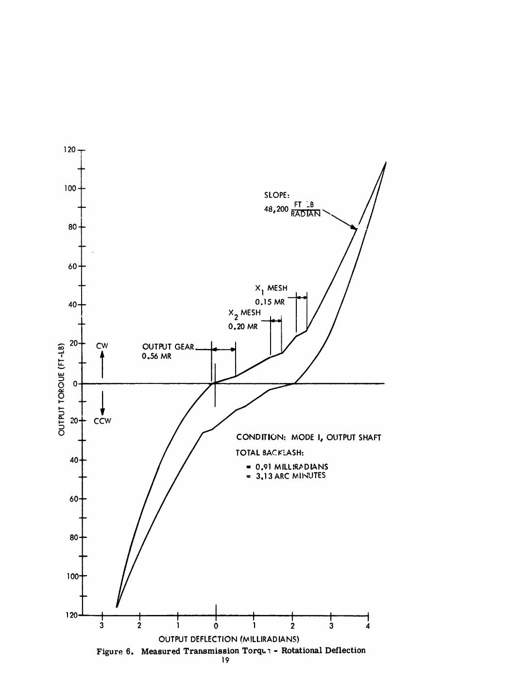
BACKLASH AND TORSIONAL STIFFNESS
The backlash and torsional stiffness of the roller-gear transmission was measured in a transmission test stand, The input shaft was securely locked to the transmission housing, while the output shaft was loaded to various torque levels and the output shaft
rotational deflection noted. The unit was tested up to 115 ft-lbs in both a clockwise and a counterclockwise direction. The test run was continuous to assure a valid hysteresis loop,
The measured transmission torque-deflection curve is shown in Figure 6; the back-
lash and stiffness values determined from this curve are summarized in Table 6,
TABLE 6
ROLLER-GEAR TRANSMISSION BACKLASH AND TORSIONAL STIFFNESS (MODE I)
(At Output)
Backlash Torsional (at 80 ft-lb output)
3.2 arc min 48,200 ft-lb/radian
I OUTPUT TORQUE VERSUS INPUT COMMAND
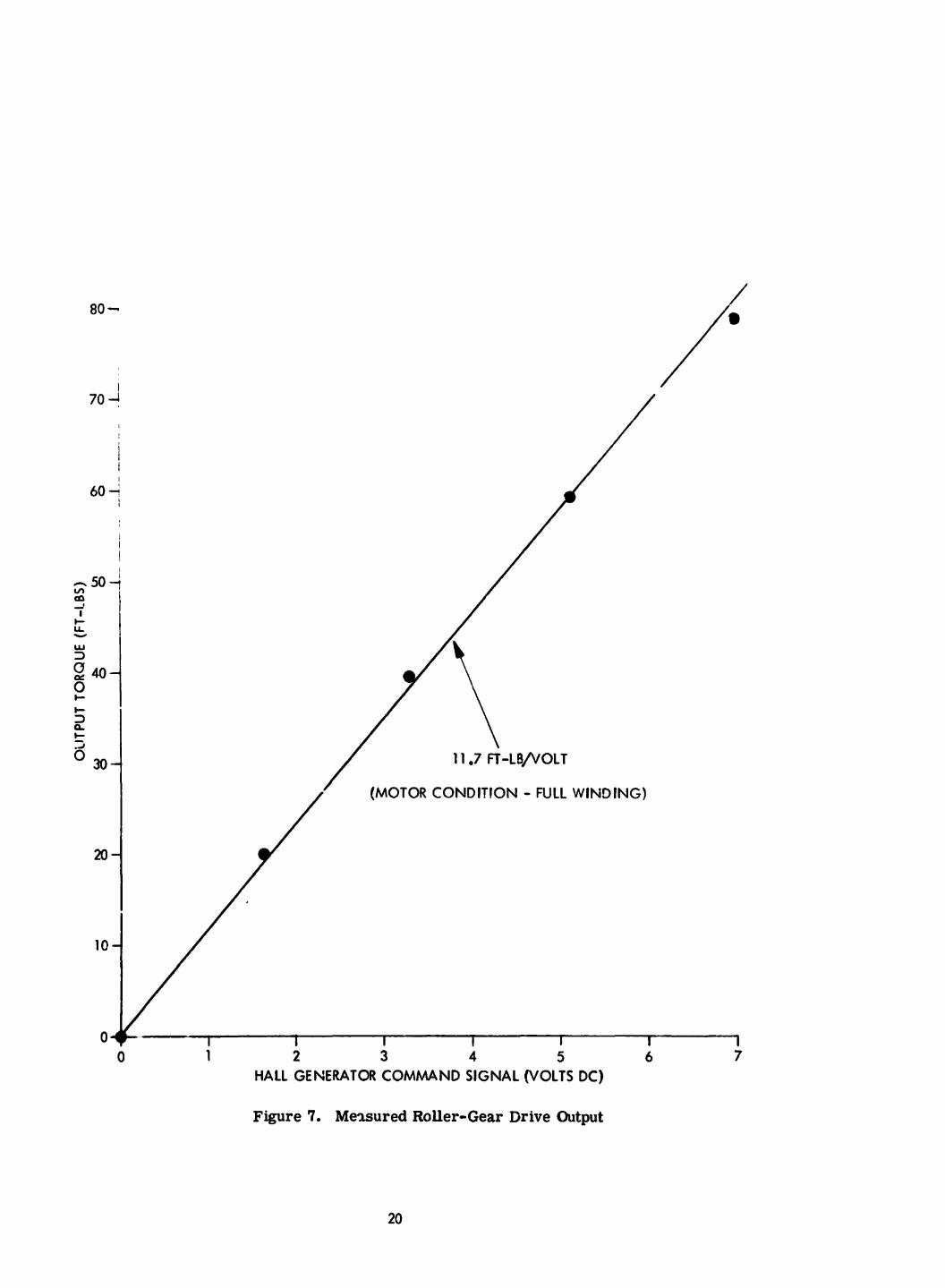
A check was made of output torque versus input command signal by connecting the brushless dc motor to the electronics and loading the output with a given torque. Al l data was taken at lo^ (10 rpm) to zero speed. The test results are shown in Figure 7. The torque versus input is lifrear up to 80 ft-lb, with a gain of 11.7 ft-lb/ volt (the electsonics gain was deliberately set up to provide f u l l output torque for about 7 volts input).
18
1 2 0 T
80 - i
I I I 1 I I 1 0 1 2 3 4 5 6 7
HALL GENERATOR COMMAND SIGNAL (VOLTS DC)
Figure 7. Mewured Ftoller-Gear Drive Output
20

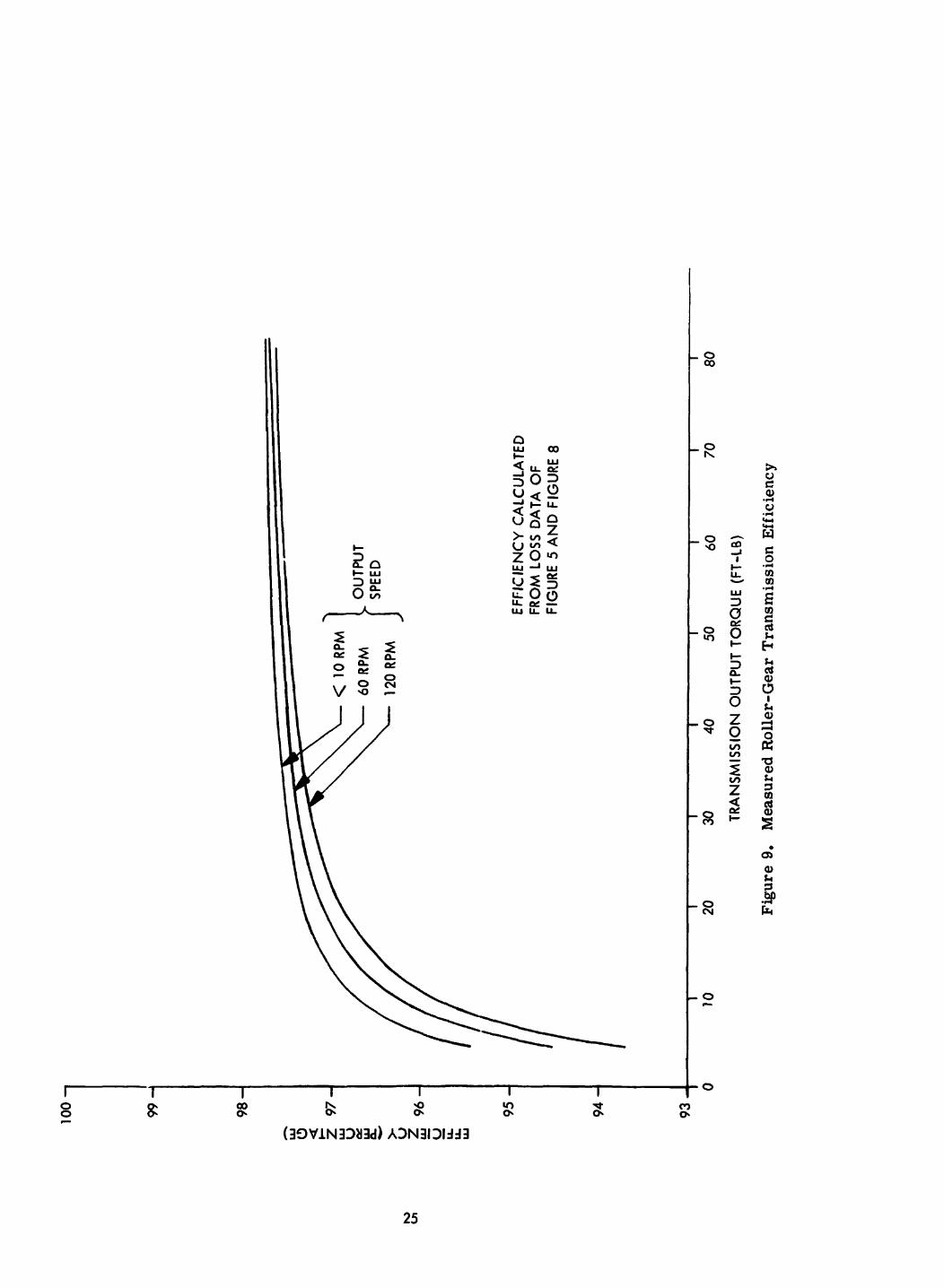
ROLLER-G EAR TRANSMISSION EFFICIENCY
The very high efficiency of the roller-gear transmission makes it difficult to ac- curately measure efficiency by the standard power-out/power-in method. General Electric has devised a unique method to accurately measure gear train efficiency at low speeds by directly measuring the transmission losses. This test was performed on the roller-gear transmission to determine low speed efficiency. The efficiency at higher speeds was then calculated by adding in the earlier measured transmission
viscous losses (Figure 5). It is felt that his results in quite accurate efficiency values, since the efficiency changes little in this design speed range (0-120 rpm at output ) . The low speed transmission efficiency consists basically of measuring the transmis- sion friction at various output torques. This is done by producing an output torsional load by applying b fixed weight to a moment a r m attached to the transmission output shaft. F'or a n g l ~ near the horizontal plane, the applied torque is effectively constant and dependent on the welght applied at the er.d of the moment arm. A torque command sufficient to raise the weights at a slow rate is applied. As the weight passes through the horizonb.1 plane, the input signal voltage required is recorded. The command signal is then aecreased so that the drive assembly output is slightly less t h a the applied torque permitting the weights to back-drive the transmission. The signal voltage is again reccrded as the arm passes through the horizontal position.
Now note that the output torque in the above two conditions is given by:
I When raisirg weghts T = Tw +Tf r I When lowering we@ts Tg = T w - T f
Where:
- - T
- TQ - = torque due to weights T
- -
output torque when raising weights
output torque when lowering weights r
W
roller-gear drive friction torque Tf 21
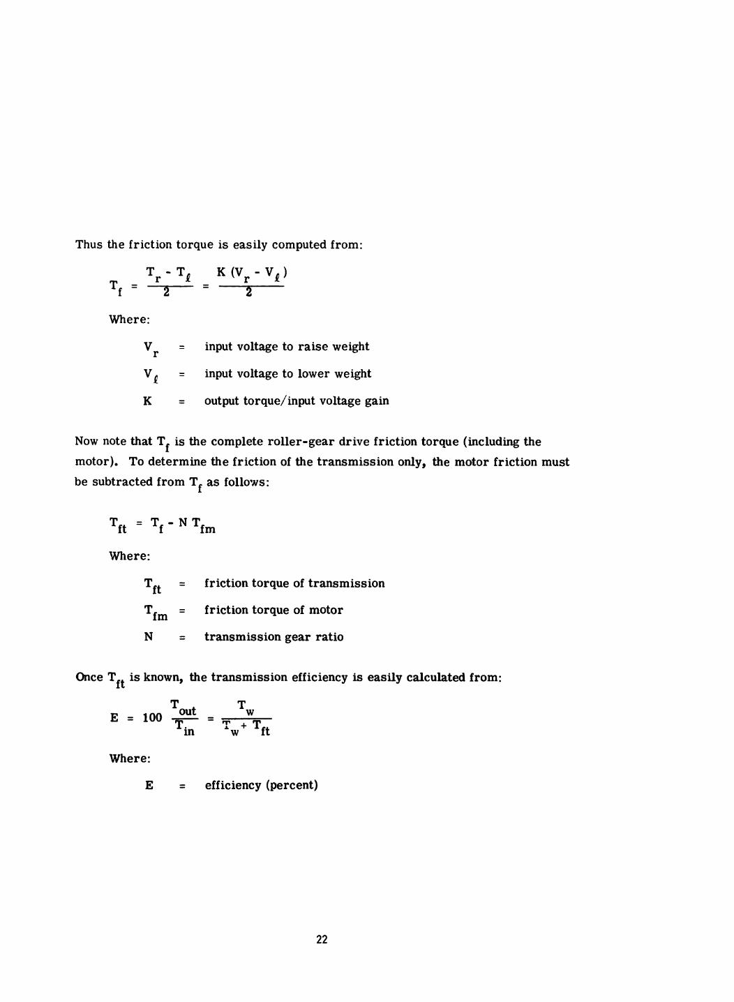
Thus the friction torque is easily computed from:
Where:
input voltage to raise weight V
Vi = input voltage to lower weight
K = output torque/input voltage gain
= r
Now note that T is the complete roller-gear drive friction torque (including the f motor). To determine the friction of the transmission only, the motor friction must be subtracted from Tf as follows:
fm Tft = Tf - N T
Where:
Tft = friction torque of transmission
= friction torque of motor 'fin N = transmission gear ratio
Once T is known, the transmission efficiency is easily calculated from: ft r n m
1 W out -
in Tw+ Tft
1
E = 100 - - T
Where:
E = efficiency (percent)
22
By repeating the above for various values of weights, the transmission loaded friction and hence the transmissiop efficiency is determined at various output torques.
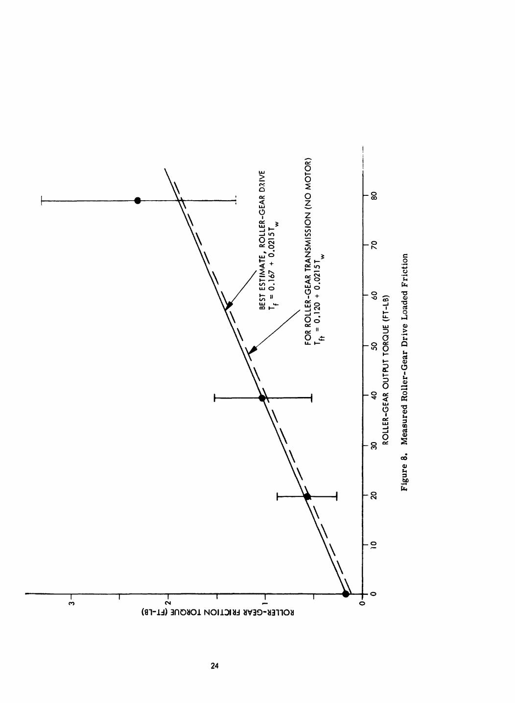
The above test was performed on the roller-gear drive for steps of applied torque up to 80 ft-lbs, and the results are shown in Figures 8 and 9. Figure 8 shows the measured loaded friction for the complete roller-gear drive (transmission plus motor) and for the transmission only. Figure 9 shows the low speed transmission efficiency as calculated from the measured loaded friction data. The estimated high speed efficiency is also calculated by including the transmission viscous losses measured earlier (see Figure 5).
The very high efficiency of the roller-gear transmission is obvious from Figure 9.
23
+ 0- Y
w 3 0
m o - 0
+
24
0 0 c
25
Section 4
CONCLUSIONS AND RECOMMENDATIONS
CONCLUSIONS
The roller-gear drive developed on this contract has demonstrated the basic per- formance capability of the roller-gear transmission and provided an indication of its potential usefulness. Very high efficiency and very low friction characteristics have been demonstrated in a compact, low weight unit.
The roller-gear drive consisting of a roller-gear transmission driven by a brushless dc motor appears to be an excellent configuration, and should provide excellent characteristics for a wide-range of power drive and servo drive applications.
Further development and testing is required of the roller-gear transmission to verify its capability and determine its long t e rm stability and life.
RECOMMENDATIONS
It is recommended:
1. That further testing of the roller-gear drive developed on this contract be performed. Tests should definitely be performed to determine characteristics in the mode 11 servo drive configuration. Added tests in the mode I power drive configuration should also be performed.
2. That development of a roller-gear drive for a specific application be per- formed, with several units being fabricated and extensively tested. Two possible applications are: a) as a wheel power drive for electric-driven vehicles, and b) as a CMG gimbal servo drive.
26
DEFINITION OF TERMS
For the purposes of this report, the following definitions apply:
1. Roller-Gear Drive - refers to the complete unit consisting of the roller- gear transmission drive by the brushless dc motor.
2. Roller-Gear Transmission - refers to the roller-gear reduction unit (roller-gear drive without the motor).
3. Brushless DC Motor - refers to the 5 ft-lb brushless dc motor developed on this contract (GE drawing 113D9398).
27
APPENDIX A DRAWING STRUCTURE
The roller-gear drive developed on this contract is defined by GE Drawing 184F792, Assembly - Torque and Transmission, and the associated parts list.
The above drawings do not reflect the extra bearing added at the input shaft to increase in?ut shaft stiffness (see Section 2). This modification is defined in GE sketch SK PLS-021571, Housiw and Shaft Assembly. This sketch has been included in the drawing data package.
Drawing 184F796, Fixture - Transmission, which defines test fixture pieces used to test the roller-gear drive has also been included in the drawing data package.
28
REFERENCES
1. Hertzendorf, B. H., "Interim Report - Brushless DC Motor", contract No. NAS8-26213, November 1970 (GE Report No. ACD 10,056)
2. Kasvytis, A. L., and Bauer, J. E., "Parametric Study on the Roller-Gear Reduction Drive", June 1965 (TRW Report ER-5637 on USA AVLABS Technical Report 64-29)
3. Nasvytis, A. L., "Multiroller Planetary Friction Drives", SAE Paper 660763, October 1966
4. Seminski, R. B., "Roller-Gear Drive Design", November 1970 (GE Unit Memo 70-91-23)
5. Seminski, R. B., "Roller-Gear Drive Analysis and Data prepared by A. L. Sasvytis", December 1970 (GE Unit Memo 70-91-33)
29