acd lab manual
TRANSCRIPT
7/27/2019 Acd Lab Manual
http://slidepdf.com/reader/full/acd-lab-manual 1/31
EXP NO : 1
Study of Riveted Joints
INTRODUCTION :
Riveted joints are universally used in various engineering structures such asbridges, ships, aircrafts, boilers and cranes etc., In case or riveting, the holes are
made in the plates which are to be connected and rivets are inserted into the holes
of the plates. The rivets are generally made of steel. The rivets are hammered for
permanent fastenings. Recently, however welding has replaced the latter consumes
more manual and labour input.
TERMINOLOGY :
PITCH (P) : The distance between the centers of adjacent rivets measured on a
row.
BACK PITCH OR TRANSVERSE PITCH (P): The distance between two adjacent in
the same plot. It varies from 0.5 to 2.5 times the rivet diameter.
DIAGONAL PITCH(Pd ) : The distance between the centers of rivet and nearest
edge of the plate.
GUAGE LINE : The line of the rivets parallel to the direction of stress is called
gauge line.
GAUGE DISTANCE : The distance between two consecutive rivets is the gauge
distance.
REPEATING SECTION : A group of rivets whose pattern repeats itself along the
length of the joint is referred to as repeating section.
NOMINAL DIAMETER : The diameter of the cold rivet measured before driving is
referred as nominal diameter.
EDGE DISTANCE : The distance of the edge of the member or the cover plates
from extreme rivet hole is edge distance.
TYPES OF RIVETED JOINTS :
The two types of joints are :
• Lap joint
• Butt joint
7/27/2019 Acd Lab Manual
http://slidepdf.com/reader/full/acd-lab-manual 2/31
LAP JOINT :
When the ends of the plate overlap each other, the joint is known as lap joint. Thelap joints are classified as :
• Single riveted lap joint
• Double riveted lap joint
• Triple riveted lap joint
In case of the lap joints, if the joint is made by only one row of rivets
used for connecting two plates, it is known as the single riveted lap joint. A joint
with two rows of rivets used for the connection is known as double riveted lap joint,
whereas a joint with three rows of rivets used for connecting two plates is known as
triple riveted lap joint.
BUTT JOINT :
In case of butt joint, the edges of the two plates to be joined together butt
against each other and a cover plate is placed either on one side or on both the
sides of the two main plates.
In case of the butt joint atleast two rows of rivets on each side of the joint are
required.
The butt joints are classified as
• Single riveted butt joint
• Double riveted butt joint
• Triple riveted butt joint
In case of a single riveted butt joint, one row of rivets is used on each side of
the joint. Hence in the total, there are two rows of rivets used on each side of the
joint and hence in total, three or four rows of rivets are in a double riveted butt
joint. In case of a triple riveted butt joint, three rows of rivets are used on each side
of the joint.
In addition to the above, the following are also the types of riveted joints :
• Chain riveted joints
• Zig-zag riveted joints
• Diamond riveted joints
7/27/2019 Acd Lab Manual
http://slidepdf.com/reader/full/acd-lab-manual 3/31
CHAIN RIVETED JOINTS :
A chain riveted joint is that in which every rivet of a row is opposite to other
rivet of the other row.
ZIG-ZAG RIVETED JOINTS :
A zig-zag riveted joints is that in which the spacing of the rivets is staggered
in such a way that every rivet is in the middles of two rivets of the opposite row.
ADVANTAGES :
• Riveted joint is the only method of making permanent connections of alloys
like aluminium for which so far there is no reliable method of power welding.
• Riveted Joints damp the vibration of structures.
DISADVANTAGES :
• More material is required due to large weight of rivets.
• 3.5%-4% of the weight of the structure is riveted joint while that of welded
joint is 1%-1.5% of the structure.
• Higher labour input (layout, punching ar drilling holes)
• Riveting process is more complicated and less productive than welding.
7/27/2019 Acd Lab Manual
http://slidepdf.com/reader/full/acd-lab-manual 4/31
EXP. No. 2
STUDY OF TYPICAL WING STRUCTURE
WING STRUCTURE :
A wing is a surface used to produce lift and therefore flight, for travel in theair or another gaseous medium. The wing shape is usually an airfoil. The first use of the word was for the foremost limbs of birds, but has been extended to include thewings of insects, bats and pterosaurs and also man-made devices.
A wing is a device for generating lift. Its aerodynamic quality , expressed as aLift-to-drag ratio, can be up to 60 on some gliders. This means that a significantly
smaller thrust force can be applied to propel the wing through the air in order toobtain a specified lift.
Uses :
A common use of wings is in flight, using forward motion to create verticallift, but wings are also used to produce down force, as in racecars. A sail boat moves by using sails and a keel like vertical wings to produce lift (in the horizontalplane).
Terms related to aircraft wings
• Leading edge: the front edge of the wing• Trailing edge: the back edge of the wing
• Span: distance from wing tip to wing tip
• Chord: distance from wing leading edge to wing trailing edge, usuallymeasured parallel to the long axis of the fuselage
• Aspect ratio: ratio of span to standard mean chord
• Aerofoil (or Airfoil in US English): the shape of the top and bottom surfaceswhen viewed as cross sections cut from leading edge to trailing edge.
• Sweep angle: the angle between the perpendicular to the design centerline of the wing in the wing plane, and either the leading edge or ¼ chord line.
• Twist: gradual change of the airfoil (aerodynamic twist ) and/or angle of incidence of the wing cross-sections (geometrical twist ) along the span.
Design features :
Aero plane wings may feature some of the following:
7/27/2019 Acd Lab Manual
http://slidepdf.com/reader/full/acd-lab-manual 5/31
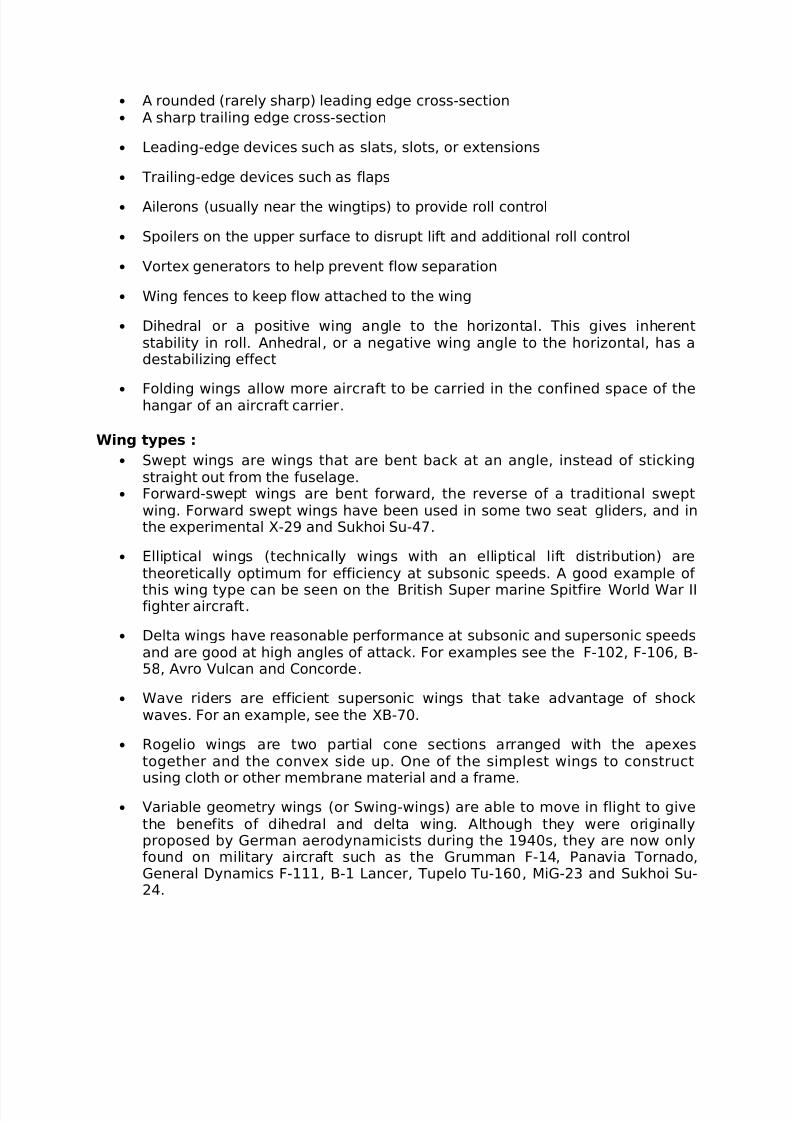
• A rounded (rarely sharp) leading edge cross-section• A sharp trailing edge cross-section
• Leading-edge devices such as slats, slots, or extensions
• Trailing-edge devices such as flaps
• Ailerons (usually near the wingtips) to provide roll control
• Spoilers on the upper surface to disrupt lift and additional roll control
• Vortex generators to help prevent flow separation
• Wing fences to keep flow attached to the wing
• Dihedral or a positive wing angle to the horizontal. This gives inherentstability in roll. Anhedral, or a negative wing angle to the horizontal, has adestabilizing effect
•
Folding wings allow more aircraft to be carried in the confined space of thehangar of an aircraft carrier.
Wing types :
• Swept wings are wings that are bent back at an angle, instead of stickingstraight out from the fuselage.
• Forward-swept wings are bent forward, the reverse of a traditional sweptwing. Forward swept wings have been used in some two seat gliders, and inthe experimental X-29 and Sukhoi Su-47.
• Elliptical wings (technically wings with an elliptical lift distribution) aretheoretically optimum for efficiency at subsonic speeds. A good example of
this wing type can be seen on the British Super marine Spitfire World War II fighter aircraft.
• Delta wings have reasonable performance at subsonic and supersonic speedsand are good at high angles of attack. For examples see the F-102, F-106, B-58, Avro Vulcan and Concorde.
• Wave riders are efficient supersonic wings that take advantage of shockwaves. For an example, see the XB-70.
• Rogelio wings are two partial cone sections arranged with the apexestogether and the convex side up. One of the simplest wings to constructusing cloth or other membrane material and a frame.
• Variable geometry wings (or Swing-wings) are able to move in flight to givethe benefits of dihedral and delta wing. Although they were originallyproposed by German aerodynamicists during the 1940s, they are now onlyfound on military aircraft such as the Grumman F-14, Panavia Tornado,General Dynamics F-111, B-1 Lancer, Tupelo Tu-160, MiG-23 and Sukhoi Su-24.
7/27/2019 Acd Lab Manual
http://slidepdf.com/reader/full/acd-lab-manual 6/31
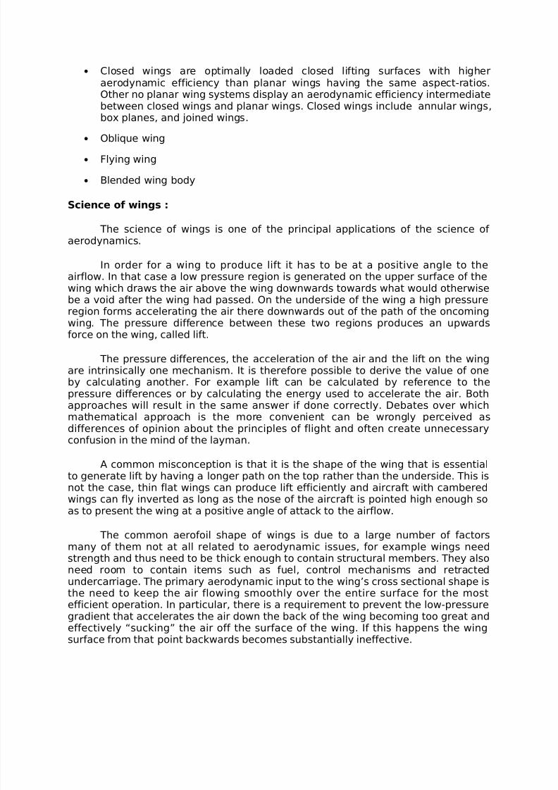
• Closed wings are optimally loaded closed lifting surfaces with higheraerodynamic efficiency than planar wings having the same aspect-ratios.Other no planar wing systems display an aerodynamic efficiency intermediatebetween closed wings and planar wings. Closed wings include annular wings,box planes, and joined wings.
• Oblique wing
• Flying wing
• Blended wing body
Science of wings :
The science of wings is one of the principal applications of the science of aerodynamics.
In order for a wing to produce lift it has to be at a positive angle to the
airflow. In that case a low pressure region is generated on the upper surface of thewing which draws the air above the wing downwards towards what would otherwisebe a void after the wing had passed. On the underside of the wing a high pressureregion forms accelerating the air there downwards out of the path of the oncomingwing. The pressure difference between these two regions produces an upwardsforce on the wing, called lift.
The pressure differences, the acceleration of the air and the lift on the wingare intrinsically one mechanism. It is therefore possible to derive the value of oneby calculating another. For example lift can be calculated by reference to thepressure differences or by calculating the energy used to accelerate the air. Bothapproaches will result in the same answer if done correctly. Debates over which
mathematical approach is the more convenient can be wrongly perceived asdifferences of opinion about the principles of flight and often create unnecessaryconfusion in the mind of the layman.
A common misconception is that it is the shape of the wing that is essentialto generate lift by having a longer path on the top rather than the underside. This isnot the case, thin flat wings can produce lift efficiently and aircraft with camberedwings can fly inverted as long as the nose of the aircraft is pointed high enough soas to present the wing at a positive angle of attack to the airflow.
The common aerofoil shape of wings is due to a large number of factorsmany of them not at all related to aerodynamic issues, for example wings needstrength and thus need to be thick enough to contain structural members. They alsoneed room to contain items such as fuel, control mechanisms and retractedundercarriage. The primary aerodynamic input to the wing’s cross sectional shape isthe need to keep the air flowing smoothly over the entire surface for the mostefficient operation. In particular, there is a requirement to prevent the low-pressuregradient that accelerates the air down the back of the wing becoming too great andeffectively “sucking” the air off the surface of the wing. If this happens the wingsurface from that point backwards becomes substantially ineffective.
7/27/2019 Acd Lab Manual
http://slidepdf.com/reader/full/acd-lab-manual 7/31
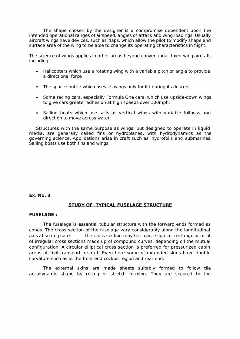
The shape chosen by the designer is a compromise dependent upon theintended operational ranges of airspeed, angles of attack and wing loadings. Usuallyaircraft wings have devices, such as flaps, which allow the pilot to modify shape andsurface area of the wing to be able to change its operating characteristics in flight.
The science of wings applies in other areas beyond conventional fixed-wing aircraft,
including:
• Helicopters which use a rotating wing with a variable pitch or angle to providea directional force
• The space shuttle which uses its wings only for lift during its descent
• Some racing cars, especially Formula One cars, which use upside-down wingsto give cars greater adhesion at high speeds over 100mph.
• Sailing boats which use sails as vertical wings with variable fullness and
direction to move across water.
Structures with the same purpose as wings, but designed to operate in liquidmedia, are generally called fins or hydroplanes, with hydrodynamics as thegoverning science. Applications arise in craft such as hydrofoils and submarines.Sailing boats use both fins and wings.
Ex. No. 3
STUDY OF TYPICAL FUSELAGE STRUCTURE
FUSELAGE :
The fuselage is essential tubular structure with the forward ends formed as
cones. The cross section of the fuselage vary considerably along the longitudinal
axis at some places the cross section may Circular, elliptical, rectangular or atof irregular cross sections made up of compound curves, depending oil the mutual
configuration. A circular elliptical cross section is preferred for pressurized cabin
areas of civil transport aircraft. Even here some of extended skins have double
curvature such as at the front end cockpit region and rear end.
The external skins are made sheets suitably formed to follow tile
aerodynamic shape by rolling or stretch forming. They are secured to the
7/27/2019 Acd Lab Manual
http://slidepdf.com/reader/full/acd-lab-manual 8/31
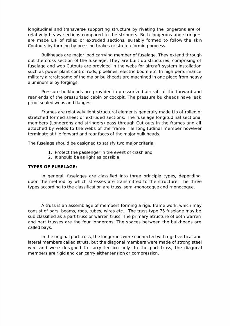
longitudinal and transverse supporting structure by riveting the longerons are of'
relatively heavy sections compared to the stringers. Both longerons and stringers
are made LIP of rolled or extruded sections, suitably formed to follow the skin
Contours by forming by pressing brakes or stretch forming process.
Bulkheads are major load carrying member of fuselage. They extend throughout the cross section of the fuselage. They are built up structures, comprising of
fuselage and web Cutouts are provided in the webs for aircraft system Installation
such as power plant control rods, pipelines, electric boom etc. In high performance
military aircraft some of the ma or bulkheads are machined in one piece from heavy
aluminum alloy forgings.
Pressure bulkheads are provided in pressurized aircraft at the forward and
rear ends of the pressurized cabin or cockpit. The pressure bulkheads have leak
proof sealed webs and flanges.
Frames are relatively light structural elements generally made Lip of rolled or
stretched formed sheet or extruded sections. The fuselage longitudinal sectional
members (Longerons and stringers) pass through Cut outs in the frames and all
attached by welds to the webs of the frame Tile longitudinal member however
terminate at tile forward and rear faces of the major bulk heads.
The fuselage should be designed to satisfy two major criteria.
1. Protect the passenger in tile event of crash and2. It should be as light as possible.
TYPES OF FUSELAGE:
In general, fuselages are classified into three principle types, depending,
upon the method by which stresses are transmitted to the structure. The three
types according to the classification are truss, semi-monocoque and rnonocoque.
A truss is an assemblage of members forming a rigid frame work, which may
consist of bars, beams, rods, tubes, wires etc... The truss type 75 fuselage may be
sub classified as a part truss or warren truss. The primary Structure of both warren
and part trusses are the four longerons. The spaces between the bulkheads are
called bays.
In the original part truss, the longerons were connected with rigid vertical and
lateral members called struts, but the diagonal members were made of strong steel
wire and were designed to carry tension only. In the part truss, the diagonal
members are rigid and can carry either tension or compression.
7/27/2019 Acd Lab Manual
http://slidepdf.com/reader/full/acd-lab-manual 9/31
In warren truss, the longerons are connected with only diagonal members.
Normally all members in the truss are capable of carrying both tension and
compression. When the load is acting in one direction compression loads are carried
to all other members as a tension loads.
EXP. No. 4
STUDY OF WELDED JOINTS
INTRODUCTION:
Welding is the process of joining similar metals by the application of heat. It
can be done with or without the application of pressure or filter metal called
electrode. If the pressure is used for joining the 2 parts the process is known as
forge welding. Whereas if the 2 parts are joined without any pressure, but if
7/27/2019 Acd Lab Manual
http://slidepdf.com/reader/full/acd-lab-manual 10/31
separate weld metal is used it is called fusion welding. The joints so formed are
known as welding joints.
TYPES OF WELDED JOINT :
The welded joints are classified according to the method of joining or Butt,
Lap, Strapped and corner jointed. The important types of welded joints are
1. Butt weld joint2. Fillet weld joint or lap weld joint3. Plug or slot weld joint.
BUTT WELD JOINT :
It is a joint in which the edges of two member butt (tough) against each
other. The two members are jointed together by the welding.
This equation is also used to calculate the strength of the Butt weld joint. The
following types of butt weld joints are mostly used.
1. Square Butt weld joint2. Single V-Butt weld3. Single U-Butt weld4. Double V-Butt weld5. Double U-Butt weld6. T Butt weld
FILLET WELD JOINT LAP JOINT :
It is a joint in which the two members overlap or meet each other at about
90º and the two members are joined together by welding. It is of approximately
triangular cross corner joints.
The fillet weld may be subjected to a load P as shown in above figure. It is
clear in case of shear stress, while in fig it is assumed to a combination of normal
and shear stress. However, it is a general practice to design for both the cases,
assuming the failure to occur at the throat by shearing.
EXP NO : 5
DESIGN OF CAM WITH UNIFORM MOTION WITH KNIFE – EDGED FOLLOWER
Aim :
To design a cam profile with knife edged follower with uniform
motion for the given specifications using software.
7/27/2019 Acd Lab Manual
http://slidepdf.com/reader/full/acd-lab-manual 11/31
Given Conditions:
Stroke = 70 mm
Rise angle = 120º
Dwell angle = 60º
Fall angle = 120º
Dwell angle = 60º
Minimum radius of the cam = 60 mm
Follower Type = Knife Edge Follower
Motion Type = Uniform Motion
Software Used:
SolidWorks2010
Procedure:
1. The type of follower and the motion for cam motion is noted
2. The stroke length or the lift value is been noted
3. The motion diagram for the motion of the cam is drawn
4. The angles of rise, fall and dwell are noted
5. The lift values of motion diagram is shifted to cam profile
diagram
6. The software is used for drawing the diagram as per the
specification
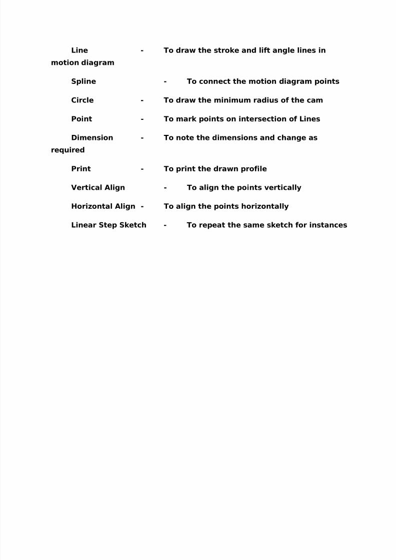
Commands Used in Software :
Line - To draw the stroke and lift angle lines in
motion diagram
Spline - To connect the motion diagram points
Circle - To draw the minimum radius of the cam
7/27/2019 Acd Lab Manual
http://slidepdf.com/reader/full/acd-lab-manual 12/31
Point - To mark points on intersection of Lines
Dimension - To note the dimensions and change as
required
Print - To print the drawn profile
Vertical Align - To align the points vertically
Horizontal Align - To align the points horizontally
Linear Step Sketch - To repeat the same sketch for instances
7/27/2019 Acd Lab Manual
http://slidepdf.com/reader/full/acd-lab-manual 13/31
Result:
Thus the cam profile of the cam with Knife edged follower with
uniform motion is drawn as per the specification using Solid works 2010.
EXP NO : 6
DESIGN OF CAM WITH SIMPLE HARMONIC MOTION WITH KNIFE – EDGED
FOLLOWER
Aim :
To design a cam profile with knife edged follower with simple
harmonic motion for the given specifications using software.
Given Conditions:
Stroke = 90 mm
Rise angle = 180º
Dwell angle = 60º
Fall angle = 60º
Dwell angle = 60º
Minimum radius of the cam = 70 mm
Follower Type = Knife Edge Follower
Motion Type = Simple Harmonic Motion
Software Used:
SolidWorks2010
Procedure:
7/27/2019 Acd Lab Manual
http://slidepdf.com/reader/full/acd-lab-manual 14/31
1. The type of follower and the motion for cam motion is noted
2. The stroke length or the lift value is been noted
3. The motion diagram for the motion of the cam is drawn
4. The angles of rise, fall and dwell are noted
5. The lift values of motion diagram is shifted to cam profile
diagram
6. The software is used for drawing the diagram as per the
specification
Commands Used in Software :
Line - To draw the stroke and lift angle lines in
motion diagram
Spline - To connect the motion diagram points
Circle - To draw the minimum radius of the cam
Point - To mark points on intersection of Lines
Dimension - To note the dimensions and change as
required
Print - To print the drawn profile
Vertical Align - To align the points vertically
Horizontal Align - To align the points horizontally
Linear Step Sketch - To repeat the same sketch for instances
7/27/2019 Acd Lab Manual
http://slidepdf.com/reader/full/acd-lab-manual 15/31
Result:
Thus the cam profile of the cam with Knife edged follower with
simple harmonic motion is drawn as per the specification using Solid
works 2010.
EXP NO : 7
DESIGN OF CAM WITH UNIFORM MOTION WITH ROLLER FOLLOWER
7/27/2019 Acd Lab Manual
http://slidepdf.com/reader/full/acd-lab-manual 16/31
Aim :
To design a cam profile with roller follower with uniform motion for
the given specifications using software.
Given Conditions:
Stroke = 70 mm
Rise angle = 90º
Dwell angle = 90º
Fall angle = 90º
Dwell angle = 90º
Minimum radius of the cam = 80 mm
Follower Type = Roller Follower
Motion Type = Uniform Motion
Roller diameter = 15 mm
Software Used:
SolidWorks2010
Procedure:
1. The type of follower and the motion for cam motion is noted
2. The stroke length or the lift value is been noted
3. The motion diagram for the motion of the cam is drawn
4. The angles of rise, fall and dwell are noted
5. The lift values of motion diagram is shifted to cam profile
diagram
6. The software is used for drawing the diagram as per the
specification
Commands Used in Software :
7/27/2019 Acd Lab Manual
http://slidepdf.com/reader/full/acd-lab-manual 17/31
Line - To draw the stroke and lift angle lines in
motion diagram
Spline - To connect the motion diagram points
Circle - To draw the minimum radius of the cam
Point - To mark points on intersection of Lines
Dimension - To note the dimensions and change as
required
Print - To print the drawn profile
Vertical Align - To align the points vertically
Horizontal Align - To align the points horizontally
Linear Step Sketch - To repeat the same sketch for instances
7/27/2019 Acd Lab Manual
http://slidepdf.com/reader/full/acd-lab-manual 18/31
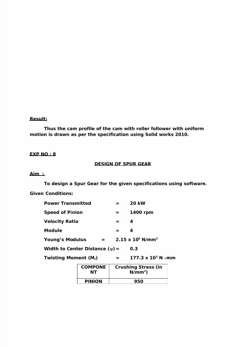
Result:
Thus the cam profile of the cam with roller follower with uniform
motion is drawn as per the specification using Solid works 2010.
EXP NO : 8
DESIGN OF SPUR GEAR
Aim :
To design a Spur Gear for the given specifications using software.
Given Conditions:
Power Transmitted = 20 kW
Speed of Pinion = 1400 rpm
Velocity Ratio = 4
Module = 4
Young’s Modulus = 2.15 x 10⁵ N/mm2
Width to Center Distance (ψ)= 0.3
Twisting Moment (Mt) = 177.3 x 10³ N –mm
COMPONENT
Crushing Stress (inN/mm2)
PINION 950
7/27/2019 Acd Lab Manual
http://slidepdf.com/reader/full/acd-lab-manual 19/31
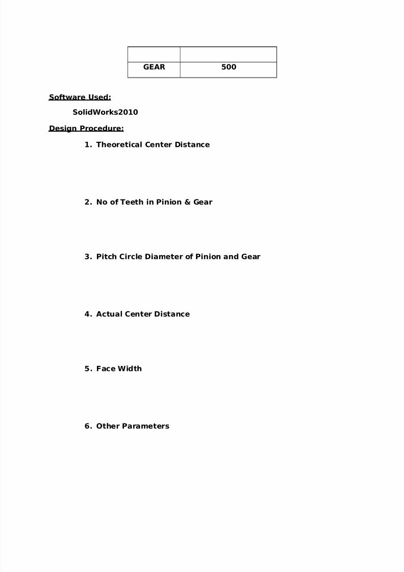
GEAR 500
Software Used:
SolidWorks2010
Design Procedure:
1. Theoretical Center Distance
2. No of Teeth in Pinion & Gear
3. Pitch Circle Diameter of Pinion and Gear
4. Actual Center Distance
5. Face Width
6. Other Parameters
7/27/2019 Acd Lab Manual
http://slidepdf.com/reader/full/acd-lab-manual 20/31
7. Tip Circle Diameter
8. Root Circle Diameter
RESULT:
Thus the Spur Gear is drawn as per the specification using Solidworks 2010.
7/27/2019 Acd Lab Manual
http://slidepdf.com/reader/full/acd-lab-manual 21/31
EXP NO : 9
DESIGN OF PISTON ROD
Aim :
To design a Piston Rod for the given specifications using software.
Given Conditions:
Bore Diameter = 200 mm
Stroke Length = 400 rpm
Length of Piston = 750 mm
Pressure = 1 N/mm
2
Factor of Safety = 5
Crushing Stress = 330 N/mm2
Slenderness Ratio (α) = 1 / 7500
Software Used:
SolidWorks2010
Design Procedure:
1. Force acting on the piston
2. Critical Load
3. Radius of Gyration
4. Diameter of the Piston Rod
7/27/2019 Acd Lab Manual
http://slidepdf.com/reader/full/acd-lab-manual 22/31
RESULT:
Thus the Piston Rod is drawn as per the specification using Solid
works 2010.
EXP NO : 10
DESIGN OF LAP JOINT
Aim :
To make a welded Joint for the given specifications using software.
Given Conditions:
Width of the plate = 90 mmThickness of the plate = 15 mm
Tensile Stress = 70 N/mm2
Shear Stress = 55 N/mm2
Software Used:
SolidWorks2010
Design Procedure:
1. Force acting on the Plate
2. Overall Length of the weld
RESULT:
Thus the welded joint is made per the specification using Solid works
2010.
7/27/2019 Acd Lab Manual
http://slidepdf.com/reader/full/acd-lab-manual 23/31
EXP NO : 11
DESIGN OF WELDED JOINT IN RECTANGULAR PLATE
Aim :
To make a welded Joint in a rectangular plate for the given
specifications using software.
Given Conditions:
Width of the plate = 100 mm
Thickness of the plate = 150 mm
Loading = 25 kN at 500 mmShear Stress = 70 N/mm2
Software Used:
SolidWorks2010
Design Procedure:
1. Shear Stress acting on the Plate
2. Height of the weld
7/27/2019 Acd Lab Manual
http://slidepdf.com/reader/full/acd-lab-manual 24/31
RESULT:
Thus the welded joint in a rectangular plate is made per the
specification using Solid works 2010.
EXP NO : 12
DESIGN OF WELDED JOINT IN CIRCULAR ROD
Aim :
To make a welded Joint in a rectangular plate for the given
specifications using software.
Given Conditions:
Diameter of the rod = 50 mm
Loading = 10 kN at 200 mm
Tensile Stress = 94 N/mm2
Software Used:
SolidWorks2010
Design Procedure:
1. Tensile Stress acting on the Plate
2. Height of the weld
7/27/2019 Acd Lab Manual
http://slidepdf.com/reader/full/acd-lab-manual 25/31
RESULT:
Thus the welded joint in a Circular Rod is made per the specification
using Solid works 2010.
EXP NO : 13
DESIGN OF RIVETED JOINTS - 1
Aim :
To make a Riveted Joint for the given specifications using software.
Given Conditions:
Width of the Specimen = 200 mm
Thickness of the Specimen = 12 mm
Tensile Stress = 80 MPa
Shear Stress = 65 MPa
Crushing Stress = 160 MPa
Software Used:
SolidWorks2010
Design Procedure:
1.Diameter of the Riveted Hole
7/27/2019 Acd Lab Manual
http://slidepdf.com/reader/full/acd-lab-manual 26/31
2.Number of Rivets
3.Dimensions
RESULT:
Thus the riveted joint is made per the specification using Solid
works 2010.
EXP NO : 14
DESIGN OF RIVETED JOINTS - 2
Aim :
To make a Riveted Joint for the given specifications using software.
Given Conditions:
Width of the Specimen = 200 mm
Thickness of the Specimen = 10 mmTensile Stress = 112 MPa
Shear Stress = 84 MPa
Crushing Stress = 200 MPa
7/27/2019 Acd Lab Manual
http://slidepdf.com/reader/full/acd-lab-manual 27/31
Software Used:
SolidWorks2010
Design Procedure:
1.Diameter of the Riveted Hole
2.Number of Rivets
3.Dimensions
RESULT:
Thus the riveted joint is made per the specification using Solid
works 2010.
EXP NO : 15
DESIGN OF RIVETED JOINTS - 3
Aim :
To make a Riveted Joint for the given specifications using software.
Given Conditions:
Width of the Specimen = 350 mm
Thickness of the Specimen = 23 mm
7/27/2019 Acd Lab Manual
http://slidepdf.com/reader/full/acd-lab-manual 28/31
Tensile Stress = 90 MPa
Shear Stress = 60 MPa
Crushing Stress = 180 MPa
Software Used:
SolidWorks2010
Design Procedure:
1.Diameter of the Riveted Hole
2.Number of Rivets
3.Dimensions
RESULT:
Thus the riveted joint is made per the specification using Solid
works 2010.
EXP NO : 16
DESIGN OF FUSELAGE STRUCTURE
7/27/2019 Acd Lab Manual
http://slidepdf.com/reader/full/acd-lab-manual 29/31
AIM:
To draw the 2D diagram of a fuselage structure using the Software
Software Used:
SolidWorks2010
FUSELAGE
The fuselage is essential tubular structure with the forward ends formed as
cones. The cross section of the fuselage vary considerably along the longitudinal
axis at some places the cross section may Circular, elliptical, rectangular or at of
irregular cross sections made up of compound curves, depending oil the mutual
configuration. A circular elliptical cross section is preferred for pressurized cabin
areas of civil transport aircraft.
RESULT:
Thus the fuselage is drawn in 2D using Solidworks
EXP NO : 17
DESIGN OF WING STRUCTURE
7/27/2019 Acd Lab Manual
http://slidepdf.com/reader/full/acd-lab-manual 30/31
AIM:
To draw the 2D diagram of a WING structure using the Software
Software Used:
SolidWorks2010
WING STRUCTURE
A wing is a surface used to produce lift and therefore flight, for travelin the air or another gaseous medium. The wing shape is usually an airfoil. The firstuse of the word was for the foremost limbs of birds, but has been extended toinclude the wings of insects, bats and pterosaurs and also man-made devices.
A wing is a device for generating lift. Its aerodynamic quality , expressed as aLift-to-drag ratio, can be up to 60 on some gliders. This means that a significantlysmaller thrust force can be applied to propel the wing through the air in order to
obtain a specified lift.
RESULT:
Thus the WING of the aircraft is drawn in 2D using Solidworks
EXP NO : 18
DESIGN OF LANDING GEAR
7/27/2019 Acd Lab Manual
http://slidepdf.com/reader/full/acd-lab-manual 31/31
AIM:
To draw the 2D diagram of a Landing Gear using the Software
Software Used:
SolidWorks2010
LANDING GEAR
A rigid landing gear is commonly found in helicopters & sailplanes. This gear
is rigidly mounted to the aircraft with no specific component to cushion the ground
contact other than through the flexing of the landing or air structure when rubber
shock cord is used. The landing gear struts are usually made of steel tubing
mounted in such a manner that a stretching action is applied to highly rubber cord.
When landing shock acquires, the cord is stretched, thus storing the impact energy
of landing. The stored energy is gradually to the aircraft during the landing roll.
RESULT:
Thus the Landing Gear of the aircraft is drawn in 2D using Solidworks