achieving the desired transformer leakage...
TRANSCRIPT
ACHIEVING THE DESIRED TRANSFORMER LEAKAGEINDUCTANCE NECESSARY IN DC-DC CONVERTERS
FOR ENERGY STORAGE APPLICATIONS
D. De, C. Klumpner, M. Rashed, C. Patel, P. Kulsangcharoen, G. Asher
Department of Electrical and Electronics EngineeringUniversity of Nottingham, NG7 2RD, UKEmail: [email protected]
Keywords: Leakage inductance Medium frequencytransformer, Winding arrangements, Winding losses.
Abstract
This paper presents a cost effective winding design andevaluation of a medium frequency isolation transformertypically used in bidirectional isolated DC/DC converters.Since leakage inductance and winding resistance of a highfrequency transformer are interdependent, any attempt toincrease the leakage inductance by adjusting the windingarrangement increases the resistance as well and impacts theefficiency. This paper proposes the use of flux diverter capsmade of a relatively small amount of ferrite material to get thedesired value of inductance whilst maintaining the losses inthe windings at reasonable levels. The proposal isexperimentally evaluated on a 5kW prototype.
1 Introduction
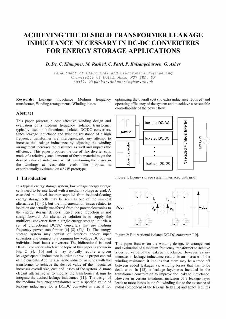
In a typical energy storage system, low voltage energy storagecells need to be interfaced with a medium voltage ac grid. Acascaded multilevel inverter supplied from isolated/floatingenergy storage cells may be seen as one of the simplestalternatives [1]–[5], but the implementation issues related toisolation are actually transferred from the power electronics tothe energy storage devices; hence price reduction is notstraightforward. An alternative solution is to supply themultilevel converter from a single energy storage unit via aset of bidirectional DC/DC converters that use mediumfrequency power transformer [6]–[8] (Fig. 1). The energystorage system may consist of batteries and/or supercapacitors and connect to a common low voltage DC bus viaindividual buck-boost converters. The bidirectional isolatedDC-DC converter which is the topic of this paper is shown inFig. 2 [9], [10] and it may typically require a givenleakage/separate inductance in order to provide proper controlof the currents. Adding a separate inductor in series with thetransformer to achieve the desired value of the inductanceincreases overall size, cost and losses of the system. A moreelegant alternative is to modify the transformer design tointegrate the desired leakage inductance [11]. The design ofthe medium frequency transformer with a specific value ofleakage inductance for a DC/DC converter is crucial for
optimizing the overall cost (no extra inductance required) andoperating efficiency of the system and to achieve a reasonablecontrollability of the power flow.
Figure 1: Energy storage system interfaced with grid.
Figure 2: Bidirectional isolated DC-DC converter [10].
This paper focuses on the winding design, its arrangementand evaluation of a medium frequency transformer to achievea desired value of the leakage inductance. However, as anyincrease in leakage inductance results in an increase of thewinding resistance; it implies that there may be a trade offbetween added leakages vs. winding losses that has to bedealt with. In [12], a leakage layer was included in thetransformer construction to improve the leakage inductance.However in certain situations, inclusion of a leakage layerleads to more losses in the foil winding due to the existence ofradial component of the leakage field [13] and hence requires
more expensive winding material (use of litz wire). Theproposal is to use a magnetic flux diverter to improve theperformance. The trade-off between the efficiency of thetransformer (resistance), the value of added leakageinductance and the other implementation aspects is evaluated.
2 System description
The design specifications for the transformer are given inTable.1 where Vp: primary voltage, Vs: secondary voltage,Po: output power, f: frequency of operation of thetransformer. The particular value of leakage inductance isimportant as a smaller value of the inductance causesinstability in the control at low current whilst a largeinductance limits the power transfer capability. In order toachieve this specification, various transformer constructionshave been investigated and implemented. In Fig. 3, threeevaluated transformers with different winding configurationsusing copper foil are shown.
Vp [rms] 325V
Vs [rms] 325V
Po [W] 5kW
f [Hz] 6kHzDesired Leakage Inductance 200-250μH
Table 1: Transformer specifications
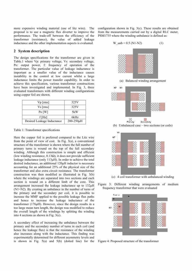
Here the copper foil is preferred compared to the Litz wirefrom the point of view of cost. In Fig. 3(a), a conventionalstructure of the transformer is shown where the full number ofprimary turns is wound on the top of the full secondarywinding. Although this construction is simple and efficient(low winding resistance, 0.13Ω), it does not provide sufficient leakage inductance (only 113μH). In order to achieve the total desired inductance, an additional 120μH inductor is necessary accounting for an additional 25% of the physical size of thetransformer and also extra circuit resistance. The transformerconstruction was then modified as illustrated in Fig. 3(b)where the windings are separated into two sections and eachsection is wound on a different limb of the core. Thisarrangement increased the leakage inductance up to 132μH (N1=N2). By creating an unbalance in the number of turns ofthe primary and the secondary per coil, it is possible toincrease the MMF applied to the possible leakage flux pathsand hence to increase the leakage inductance of thetransformer (176μH). However, since the design results in a too large mean turn length, the design was modified to reducethe overall length of the windings by splitting the windinginto 4 sections as shown in Fig. 3(c).
A secondary effect of increasing the unbalance between theprimary and the secondary number of turns in each coil (andhence the leakage flux) is that the resistance of the windingalso increases along with the inductance. This finding wasexperimentally determined for different asymmetry levels andis shown in Fig. 5(a) and 5(b) (dotted line) for the
configuration shown in Fig. 3(c). These results are obtainedfrom the measurements carried out by a digital RLC meter,PSM1735 where the winding unbalance is defined as:
W_unb = 0.5 (N1-N2) (1)
(a) Balanced winding arrangement
(b) Unbalanced case – two sections (or coils)
(c) 4 coil transformer with unbalanced winding
Figure 3: Different winding arrangements of mediumfrequency transformer that were evaluated
Figure 4: Proposed structure of the transformer
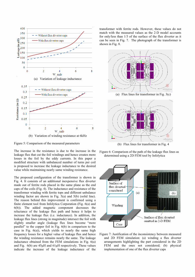
(a) Variation of leakage inductance
(b) Variation of winding resistance at 6kHz
Figure 5: Comparison of the measured parameters
The increase in the resistance is due to the increase in theleakage flux that cut the foil windings and hence creates morelosses in the foil by the eddy currents. In this paper amodified structure with unbalanced number of turns per coilis proposed to increase the leakage inductance to the desiredvalue while maintaining nearly same winding resistance.
The proposed configuration of the transformer is shown inFig. 4. It consists of an additional inexpensive flux divertermade out of ferrite rods placed in the same plane as the endcaps of the coils (Fig. 4). The inductance and resistance of thetransformer winding with ferrite tops and different unbalancewinding factor are shown in Fig. 5(a) and 5(b) (solid line).The reason behind this improvement is confirmed using afinite element tool from Infolytica Corporation (Fig. 6(a) and6(b)). The added magnetic component decreases thereluctance of the leakage flux path and hence it helps toincrease the leakage flux (i.e. inductance). In addition, theleakage flux lines (strong in magnitude) intersect the foil withslightly smaller angle (leakage flux lines become “moreparallel” to the copper foil in Fig. 6(b) in comparison to thecase in Fig. 6(a)), which yields to nearly the same highfrequency losses for a higher value of leakage flux and hencethe winding resistance remains nearly the same. The leakageinductance obtained from the FEM simulations in Fig. 6(a)and Fig. 6(b) are 45μH and 61μH respectively. These values indicate the increase of the leakage inductance of the
transformer with ferrite rods. However, these values do notmatch with the measured values as the 2-D model accountsfor only/less than 1/3 of the surface of the flux diverter as itcan be seen in Fig. 7. The photograph of the transformer isshown in Fig. 8.
(a) Flux lines for transformer in Fig. 3(c)
(b) Flux lines for transformer in Fig. 4
Figure 6: Comparison of the path of the leakage flux lines asdetermined using a 2D FEM tool by Infolytica
Figure 7: Justification of the inconsistency between measuredand 2D FEM simulation: (a) winding a flux diverterarrangements highlighting the part considered in the 2DFEM and the ones not considered; (b) physicalimplementation of one of the flux diverter caps
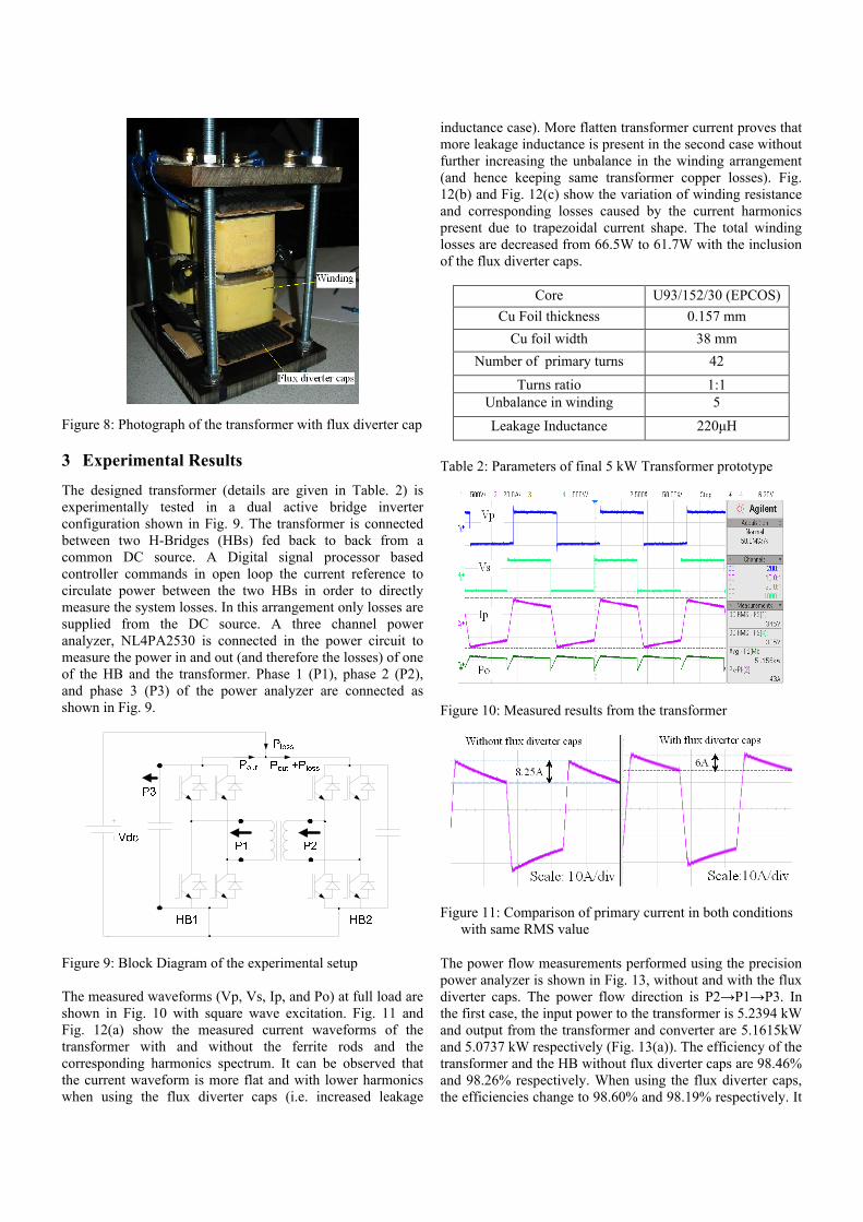
Figure 8: Photograph of the transformer with flux diverter cap
3 Experimental Results
The designed transformer (details are given in Table. 2) isexperimentally tested in a dual active bridge inverterconfiguration shown in Fig. 9. The transformer is connectedbetween two H-Bridges (HBs) fed back to back from acommon DC source. A Digital signal processor basedcontroller commands in open loop the current reference tocirculate power between the two HBs in order to directlymeasure the system losses. In this arrangement only losses aresupplied from the DC source. A three channel poweranalyzer, NL4PA2530 is connected in the power circuit tomeasure the power in and out (and therefore the losses) of oneof the HB and the transformer. Phase 1 (P1), phase 2 (P2),and phase 3 (P3) of the power analyzer are connected asshown in Fig. 9.
Figure 9: Block Diagram of the experimental setup
The measured waveforms (Vp, Vs, Ip, and Po) at full load areshown in Fig. 10 with square wave excitation. Fig. 11 andFig. 12(a) show the measured current waveforms of thetransformer with and without the ferrite rods and thecorresponding harmonics spectrum. It can be observed thatthe current waveform is more flat and with lower harmonicswhen using the flux diverter caps (i.e. increased leakage
inductance case). More flatten transformer current proves thatmore leakage inductance is present in the second case withoutfurther increasing the unbalance in the winding arrangement(and hence keeping same transformer copper losses). Fig.12(b) and Fig. 12(c) show the variation of winding resistanceand corresponding losses caused by the current harmonicspresent due to trapezoidal current shape. The total windinglosses are decreased from 66.5W to 61.7W with the inclusionof the flux diverter caps.
Core U93/152/30 (EPCOS)
Cu Foil thickness 0.157 mm
Cu foil width 38 mm
Number of primary turns 42
Turns ratio 1:1Unbalance in winding 5
Leakage Inductance 220μH
Table 2: Parameters of final 5 kW Transformer prototype
Figure 10: Measured results from the transformer
Figure 11: Comparison of primary current in both conditionswith same RMS value
The power flow measurements performed using the precisionpower analyzer is shown in Fig. 13, without and with the fluxdiverter caps. The power flow direction is P2→P1→P3. In the first case, the input power to the transformer is 5.2394 kWand output from the transformer and converter are 5.1615kWand 5.0737 kW respectively (Fig. 13(a)). The efficiency of thetransformer and the HB without flux diverter caps are 98.46%and 98.26% respectively. When using the flux diverter caps,the efficiencies change to 98.60% and 98.19% respectively. It
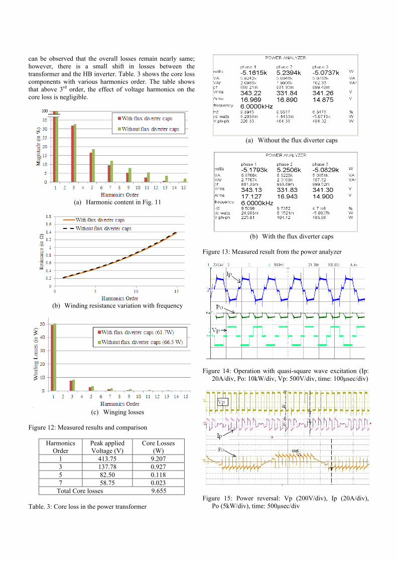
can be observed that the overall losses remain nearly same;however, there is a small shift in losses between thetransformer and the HB inverter. Table. 3 shows the core losscomponents with various harmonics order. The table showsthat above 3rd order, the effect of voltage harmonics on thecore loss is negligible.
(a) Harmonic content in Fig. 11
(b) Winding resistance variation with frequency
(c) Winging losses
Figure 12: Measured results and comparison
HarmonicsOrder
Peak appliedVoltage (V)
Core Losses(W)
1 413.75 9.2073 137.78 0.9275 82.50 0.1187 58.75 0.023
Total Core losses 9.655
Table. 3: Core loss in the power transformer
(a) Without the flux diverter caps
(b) With the flux diverter caps
Figure 13: Measured result from the power analyzer
Figure 14: Operation with quasi-square wave excitation (Ip:20A/div, Po: 10kW/div, Vp: 500V/div, time: 100μsec/div)
Figure 15: Power reversal: Vp (200V/div), Ip (20A/div),Po (5kW/div), time: 500μsec/div
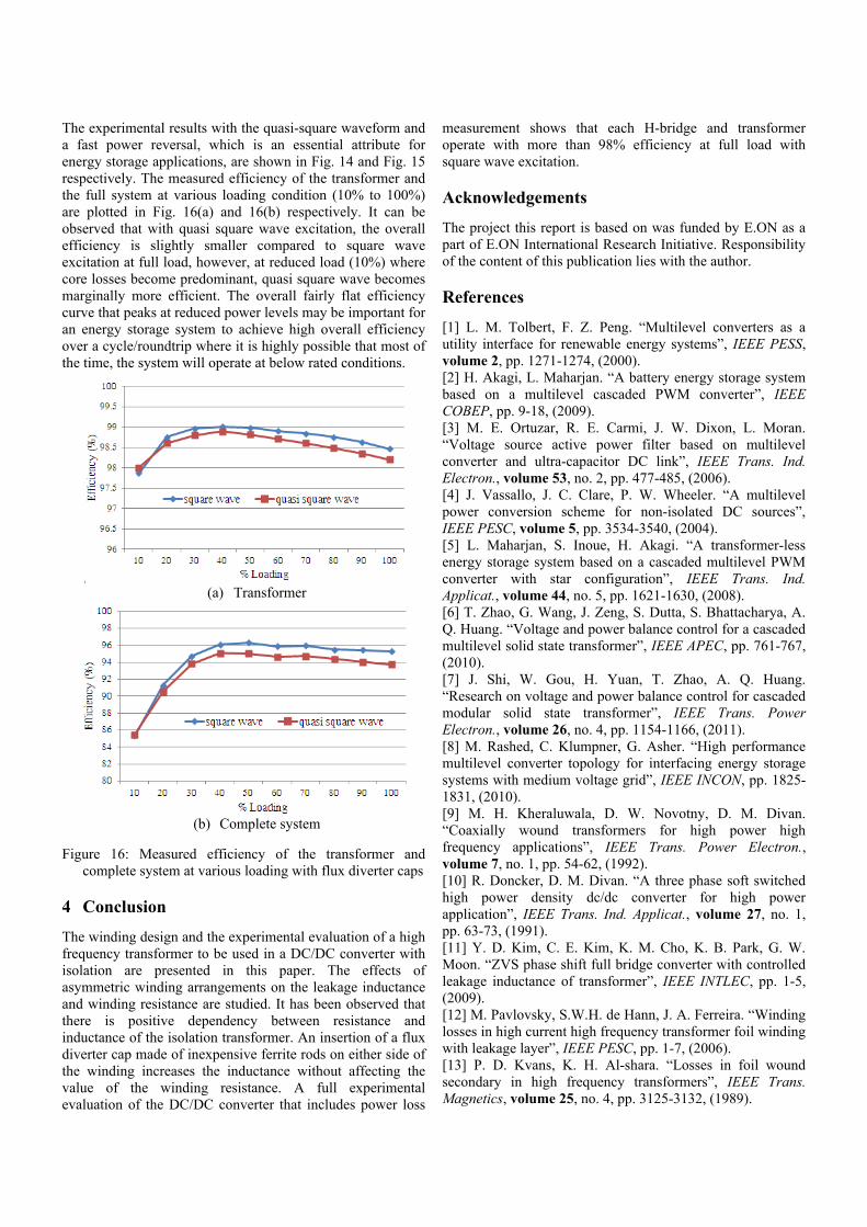
The experimental results with the quasi-square waveform anda fast power reversal, which is an essential attribute forenergy storage applications, are shown in Fig. 14 and Fig. 15respectively. The measured efficiency of the transformer andthe full system at various loading condition (10% to 100%)are plotted in Fig. 16(a) and 16(b) respectively. It can beobserved that with quasi square wave excitation, the overallefficiency is slightly smaller compared to square waveexcitation at full load, however, at reduced load (10%) wherecore losses become predominant, quasi square wave becomesmarginally more efficient. The overall fairly flat efficiencycurve that peaks at reduced power levels may be important foran energy storage system to achieve high overall efficiencyover a cycle/roundtrip where it is highly possible that most ofthe time, the system will operate at below rated conditions.
(a) Transformer
(b) Complete system
Figure 16: Measured efficiency of the transformer andcomplete system at various loading with flux diverter caps
4 Conclusion
The winding design and the experimental evaluation of a highfrequency transformer to be used in a DC/DC converter withisolation are presented in this paper. The effects ofasymmetric winding arrangements on the leakage inductanceand winding resistance are studied. It has been observed thatthere is positive dependency between resistance andinductance of the isolation transformer. An insertion of a fluxdiverter cap made of inexpensive ferrite rods on either side ofthe winding increases the inductance without affecting thevalue of the winding resistance. A full experimentalevaluation of the DC/DC converter that includes power loss
measurement shows that each H-bridge and transformeroperate with more than 98% efficiency at full load withsquare wave excitation.
Acknowledgements
The project this report is based on was funded by E.ON as apart of E.ON International Research Initiative. Responsibilityof the content of this publication lies with the author.
References
[1] L. M. Tolbert, F. Z. Peng. “Multilevel converters as autility interface for renewable energy systems”, IEEE PESS,volume 2, pp. 1271-1274, (2000).[2] H. Akagi, L. Maharjan. “A battery energy storage systembased on a multilevel cascaded PWM converter”, IEEECOBEP, pp. 9-18, (2009).[3] M. E. Ortuzar, R. E. Carmi, J. W. Dixon, L. Moran.“Voltage source active power filter based on multilevelconverter and ultra-capacitor DC link”, IEEE Trans. Ind.Electron., volume 53, no. 2, pp. 477-485, (2006).[4] J. Vassallo, J. C. Clare, P. W. Wheeler. “A multilevelpower conversion scheme for non-isolated DC sources”,IEEE PESC, volume 5, pp. 3534-3540, (2004).[5] L. Maharjan, S. Inoue, H. Akagi. “A transformer-lessenergy storage system based on a cascaded multilevel PWMconverter with star configuration”, IEEE Trans. Ind.Applicat., volume 44, no. 5, pp. 1621-1630, (2008).[6] T. Zhao, G. Wang, J. Zeng, S. Dutta, S. Bhattacharya, A.Q. Huang. “Voltage and power balance control for a cascadedmultilevel solid state transformer”, IEEE APEC, pp. 761-767,(2010).[7] J. Shi, W. Gou, H. Yuan, T. Zhao, A. Q. Huang.“Research on voltage and power balance control for cascadedmodular solid state transformer”, IEEE Trans. PowerElectron., volume 26, no. 4, pp. 1154-1166, (2011).[8] M. Rashed, C. Klumpner, G. Asher. “High performancemultilevel converter topology for interfacing energy storagesystems with medium voltage grid”, IEEE INCON, pp. 1825-1831, (2010).[9] M. H. Kheraluwala, D. W. Novotny, D. M. Divan.“Coaxially wound transformers for high power highfrequency applications”, IEEE Trans. Power Electron.,volume 7, no. 1, pp. 54-62, (1992).[10] R. Doncker, D. M. Divan. “A three phase soft switchedhigh power density dc/dc converter for high powerapplication”, IEEE Trans. Ind. Applicat., volume 27, no. 1,pp. 63-73, (1991).[11] Y. D. Kim, C. E. Kim, K. M. Cho, K. B. Park, G. W.Moon. “ZVS phase shift full bridge converter with controlledleakage inductance of transformer”, IEEE INTLEC, pp. 1-5,(2009).[12] M. Pavlovsky, S.W.H. de Hann, J. A. Ferreira. “Windinglosses in high current high frequency transformer foil windingwith leakage layer”, IEEE PESC, pp. 1-7, (2006).[13] P. D. Kvans, K. H. Al-shara. “Losses in foil woundsecondary in high frequency transformers”, IEEE Trans.Magnetics, volume 25, no. 4, pp. 3125-3132, (1989).