acid rain program policy manual - p2 infohouse · "acid rain program policy manual," and...
TRANSCRIPT

Acid Rain ProgramPolicy Manual
U.S. Environmental Protection AgencyClean Air Markets Division
Washington, D.C.
March 28, 2000


Acid Rain Program Policy Manual -- March 28, 2000 Page i
TABLE OF CONTENTS
Page
Introduction . . . . . . . . . . . . . . . . . . . . . . . . . . . . . . . . . . . . . . . . . . . . . . . . . . . . . . . . . . . . . iii
Section 1 - General . . . . . . . . . . . . . . . . . . . . . . . . . . . . . . . . . . . . . . . . . . . . . . . . . . . . . 1-1
Section 2 - SO2 Monitoring . . . . . . . . . . . . . . . . . . . . . . . . . . . . . . . . . . . . . . . . . . . . . . . 2-1
Section 3 - Flow Monitoring . . . . . . . . . . . . . . . . . . . . . . . . . . . . . . . . . . . . . . . . . . . . . . . 3-1
Section 4 - NOx Monitoring . . . . . . . . . . . . . . . . . . . . . . . . . . . . . . . . . . . . . . . . . . . . . . . 4-1
Section 5 - Opacity Monitoring . . . . . . . . . . . . . . . . . . . . . . . . . . . . . . . . . . . . . . . . . . . . 5-1
Section 6 - CO2 Monitoring . . . . . . . . . . . . . . . . . . . . . . . . . . . . . . . . . . . . . . . . . . . . . . . 6-1
Section 7 - Backup and Portable Monitoring . . . . . . . . . . . . . . . . . . . . . . . . . . . . . . . . . . 7-1
Section 8 - Relative Accuracy . . . . . . . . . . . . . . . . . . . . . . . . . . . . . . . . . . . . . . . . . . . . . 8-1
Section 9 - Bias . . . . . . . . . . . . . . . . . . . . . . . . . . . . . . . . . . . . . . . . . . . . . . . . . . . . . . . . 9-1
Section 10 - Span, Calibration, and Linearity . . . . . . . . . . . . . . . . . . . . . . . . . . . . . . . . . 10-1
Section 11 - Other QA/QC Requirements. . . . . . . . . . . . . . . . . . . . . . . . . . . . . . . . . . . . 11-1
Section 12 - Certification: Administrative/Procedural . . . . . . . . . . . . . . . . . . . . . . . . . . . 12-1
Section 13 - Recertification . . . . . . . . . . . . . . . . . . . . . . . . . . . . . . . . . . . . . . . . . . . . . . 13-1
Section 14 - DAHS, Recordkeeping, and Reporting . . . . . . . . . . . . . . . . . . . . . . . . . . . . 14-1
Section 15 - Missing Data Procedures . . . . . . . . . . . . . . . . . . . . . . . . . . . . . . . . . . . . . . 15-1
Section 16 - Scrubbers and Parametric Monitoring Procedures . . . . . . . . . . . . . . . . . . . . 16-1
Section 17 - Common, Multiple, and Complex Stacks . . . . . . . . . . . . . . . . . . . . . . . . . . 17-1
Section 18 - Conversion Procedures . . . . . . . . . . . . . . . . . . . . . . . . . . . . . . . . . . . . . . . 18-1
Section 19 - Applicability . . . . . . . . . . . . . . . . . . . . . . . . . . . . . . . . . . . . . . . . . . . . . . . . 19-1
Table of Contents
Page ii Acid Rain Program Policy Manual -- March 28, 2000
Page
Section 20 - Jurisdiction and Enforcement . . . . . . . . . . . . . . . . . . . . . . . . . . . . . . . . . . . . 20-1
Section 21 - Reference Methods as Backup Monitors . . . . . . . . . . . . . . . . . . . . . . . . . . 21-1
Section 22 - Subtractive Configurations . . . . . . . . . . . . . . . . . . . . . . . . . . . . . . . . . . . . . 22-1
Section 23 - Bypass Stacks . . . . . . . . . . . . . . . . . . . . . . . . . . . . . . . . . . . . . . . . . . . . . . 23-1
Section 24 - NOx Apportionment . . . . . . . . . . . . . . . . . . . . . . . . . . . . . . . . . . . . . . . . . . 24-1
Section 25 - Appendix D . . . . . . . . . . . . . . . . . . . . . . . . . . . . . . . . . . . . . . . . . . . . . . . . 25-1
Section 26 - Appendix E . . . . . . . . . . . . . . . . . . . . . . . . . . . . . . . . . . . . . . . . . . . . . . . . 26-1
Section 27 - NOx Mass Monitoring . . . . . . . . . . . . . . . . . . . . . . . . . . . . . . . . . . . . . . . . 27-1
Section 28 - Moisture Monitoring . . . . . . . . . . . . . . . . . . . . . . . . . . . . . . . . . . . . . . . . . . 28-1
Section 29 - Low Mass Emitters . . . . . . . . . . . . . . . . . . . . . . . . . . . . . . . . . . . . . . . . . . 29-1
Sections 30 - 32 [RESERVED]
Section 33 - NOx Alternative Emission Limit Plans . . . . . . . . . . . . . . . . . . . . . . . . . . . . . 33-1
Section 34 - RETIRED
Key Word Index . . . . . . . . . . . . . . . . . . . . . . . . . . . . . . . . . . . . . . . . . . . . . . . . . . . Index - 1
Appendix A - EPA Regional/State Acid Rain CEM Contact List . . . . . . . . . . . . . . . . . . . . A-1
Appendix B - Correspondence . . . . . . . . . . . . . . . . . . . . . . . . . . . . . . . . . . . . . . . . . . . . . B-1
Appendix C - Miscellaneous . . . . . . . . . . . . . . . . . . . . . . . . . . . . . . . . . . . . . . . . . . . . . . C-1

Acid Rain Program Policy Manual -- March 28, 2000 Page iii
INTRODUCTION
In order to reduce acid rain in the United States and Canada, Title IV of the Clean Air ActAmendments of 1990 established the Acid Rain Program. The program will cut sulfur dioxide emissions inhalf and substantially reduce nitrogen oxide emissions from electric utility plants. To achieve these reductionsat the lowest cost to society, the program employs both traditional regulatory techniques and innovative,market-based approaches. The centerpiece of the program is the allowance trading system, under whichaffected utility units are allocated "allowances" (each "allowance" permits a utility to emit one ton of SO2)based on historical fuel consumption and specified emission rates. The allowances can be traded ascommodities.
To ensure that allowances are consistently valued and to ensure that all of the projected emissionreductions are in fact achieved, it is necessary that actual emissions from each affected utility unit be accuratelydetermined. To fulfill this function, Title IV requires that affected units continuously measure and record theirSO2, NOx, and CO2 emissions, as well as volumetric flow, opacity, and diluent gas levels. Most plants willfulfill these requirements by using continuous emission monitoring systems. The EPA initially promulgatedregulations for Acid Rain Program continuous emission monitoring (CEM) requirements at 40 CFR Part 75on January 11, 1993 (58 FR 3590) and has published interim and direct final rule revisions to Part 75 as wellas technical revisions since that time. The most recent revisions include extensive rule revisions published onMay 26, 1999 (64 FR 28564) to 40 CFR Parts 72 and 75 and May 14, 1999 revisions (64 FR 26484) tothe flow test methods in 40 CFR Part 60, Appendix A.
Initially, this manual addressed policy questions involving the implementation of the Acid Rain CEMProgram. Effective with Update #7 issued in November 1995, the name of this manual was changed to the"Acid Rain Program Policy Manual," and the manual now includes questions and answers related to AcidRain Program policy issues other than Part 75 issues.
This manual provides a series of Questions and Answers that can be used on a nationwide basis toensure that the Acid Rain Program is applied consistently for all sources affected by the program. The manualincludes a general table of contents that lists the major topic area and a separate table of contents for eachtopic area that identifies the appropriate page reference for each Question and Answer applicable to thatarea. At the end of this manual, a key word index is provided that identifies for each key word the questionnumber(s) where an issue concerning that key word is addressed.
This manual is intended to be a living document. The EPA will issue new Questions and Answers asthey arise and will revise previously issued Questions and Answers as necessary to provide clarification. Itshould be noted that the materials in this manual are guidance materials only and are intended to clarify theregulations. This document is not intended, nor can it be relied upon, to create any rights enforceable by anyparty in litigation with the United States. EPA may decide to follow the guidance provided in this document,or to act at variance with this guidance, based on its analysis of the specific facts presented. This guidance

Introduction
Page iv Acid Rain Program Policy Manual --March 28, 2000
may be revised without public notice to reflect changes in EPA's approach to implementation, or to clarify andupdate text.
The contents of this manual are available to the general public through the Internet on the Acid RainHomepage. The electronic version is provided in an Adobe Acrobat file (pdf format). Updates to the manualwill be issued as separate Adobe Acrobat files. Periodically, EPA will reissue a complete manual thatincorporates the updates. This version of the manual includes the original March 11, 1993 version, andUpdates #1 through #12 to that original version. Table A, below, provides a list of the questions in thisupdate and their status (new or revised). Two new sections, 22 and 24, are also included. Section 22 dealswith Subtractive Configurations and Section 24 covers NOx Apportionment. Finally, the contact list(Appendix A) has been updated and the "Quarterly Report Review Process for Determining Final AnnualData" (part of Appendix C) has been revised (the other documents from Appendix C have not been revised).
If after reviewing the regulations and this manual, the reader still has an unresolved issue, the readershould contact the appropriate EPA Headquarters or Regional Office contact. An Acid Rain CEM Programcontact list appears in Appendix A of this manual.
In response to the recent rule revisions, and given that certain questions and answers that were time-sensitive are no longer applicable, this version of the manual "retires" a number of questions and answers. Inaddition, for ease of reference, EPA has retained the same numbering for all questions and answers fromprevious versions of the manual. The "History" information in each answer indicates when the question andanswer was originally published and when, if applicable, it was retired or revised. The table of contents foreach section also identifies which questions and answers have been retired or revised.

Introduction
Acid Rain Program Policy Manual -- March 28, 2000 Page v
Table A: New/Revised Questions
QuestionNumber
StatusQuestionNumber
StatusQuestionNumber
Status
1.13 New 10.31 New 22.3 New
1.14 New 10.32 New 22.4 New
1.15 New 10.33 New 22.5 New
1.16 New 10.34 New 22.6 New
1.17 New 10.35 New 22.7 New
2.16 New 10.36 New 22.8 New
3.26 New 10.37 New 22.9 New
3.27 New 11.6 New 22.10 New
3.28 New 13.4 Revised 22.11 New
3.29 New 13.5 Revised 22.12 New
3.30 New 13.6 Revised 24.1 New
3.31 New 14.90 New 24.2 New
3.32 New 14.91 New 24.3 New
3.33 New 14.92 New 24.4 New
3.34 New 14.93 New 24.5 New
3.35 New 14.94 New 24.6 New
4.23 New 14.95 New 24.7 New
5.6 Revised 14.96 New 24.8 New
6.5 New 14.97 New 24.9 New
7.22 New 14.98 New 24.10 New
8.30 New 14.99 New 24.11 New
8.31 New 14.100 New 24.12 New
8.32 New 14.101 New 24.13 New
8.33 New 14.102 New 25.13 New
8.34 New 15.28 New 25.14 New
8.35 New 15.29 New 25.15 New
10.28 New 15.30 New 26.19 New
10.29 New 22.1 New 29.1 New
10.30 New 22.2 New

Introduction
Page vi Acid Rain Program Policy Manual --March 28, 2000
[This page intentionally left blank.]

Acid Rain Program Policy Manual -- March 28, 2000 Page 1-i
SECTION 1GENERAL
Page
1.1 RETIRED
1.2 REVISED Time-shared Analyzers . . . . . . . . . . . . . . . . . . . . . . . . . . . . . . . . . 1-1
1.3 Acceptable Monitors . . . . . . . . . . . . . . . . . . . . . . . . . . . . . . . . . . . . . . . . . . . . 1-1
1.4 REVISED Use of Optical In-situ Monitoring . . . . . . . . . . . . . . . . . . . . . . . . . 1-2
1.5 REVISED Publication of Regulations with All Revisions . . . . . . . . . . . . . . . . . 1-3
1.6 RETIRED
1.7 RETIRED
1.8 RETIRED
1.9 RETIRED
1.10 RETIRED
1.11 Policy Manual/Guidance Updates . . . . . . . . . . . . . . . . . . . . . . . . . . . . . . . . . . . 1-4
1.12 Time Table for Implementation of Rule Revisions . . . . . . . . . . . . . . . . . . . . . . . . 1-5
1.13 Policy Manual Updates . . . . . . . . . . . . . . . . . . . . . . . . . . . . . . . . . . . . . . . . . . 1-19
1.14 Audit Checklist . . . . . . . . . . . . . . . . . . . . . . . . . . . . . . . . . . . . . . . . . . . . . . . . 1-19
1.15 PEMS . . . . . . . . . . . . . . . . . . . . . . . . . . . . . . . . . . . . . . . . . . . . . . . . . . . . . . 1-20

General Section 1
Page 1-ii Acid Rain Program Policy Manual -- March 28, 2000
Page
1.16 Exemptions From Part 60 Requirements . . . . . . . . . . . . . . . . . . . . . . . . . . . . . 1-20
1.17 Rule Revisions and OTC NBP Sources . . . . . . . . . . . . . . . . . . . . . . . . . . . . . 1-21
Section 1 General
Acid Rain Program Policy Manual -- March 28, 2000 Page 1-1
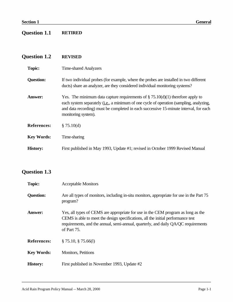
Question 1.1 RETIRED
Question 1.2 REVISED
Topic: Time-shared Analyzers
Question: If two individual probes (for example, where the probes are installed in two differentducts) share an analyzer, are they considered individual monitoring systems?
Answer: Yes. The minimum data capture requirements of § 75.10(d)(1) therefore apply toeach system separately (i.e., a minimum of one cycle of operation (sampling, analyzing,and data recording) must be completed in each successive 15-minute interval, for eachmonitoring system).
References: § 75.10(d)
Key Words: Time-sharing
History: First published in May 1993, Update #1; revised in October 1999 Revised Manual
Question 1.3
Topic: Acceptable Monitors
Question: Are all types of monitors, including in-situ monitors, appropriate for use in the Part 75program?
Answer: Yes, all types of CEMS are appropriate for use in the CEM program as long as theCEMS is able to meet the design specifications, all the initial performance testrequirements, and the annual, semi-annual, quarterly, and daily QA/QC requirementsof Part 75.
References: § 75.10, § 75.66(l)
Key Words: Monitors, Petitions
History: First published in November 1993, Update #2

General Section 1
Page 1-2 Acid Rain Program Policy Manual -- March 28, 2000
EAV ' SAV (MPLCCPL
Question 1.4 REVISED
Topic: Use of Optical In-situ Monitoring
Question: Can I use an optical in-situ monitoring system under the Acid Rain Program? If so,how do I challenge the system with calibration gases and what procedure should I useto calculate the required gas tag values?
Answer: Yes. An optical in-situ system may be used so long as it is approved by the Acid RainProgram via issuance of a monitoring system certification. This means the system mustundergo all required tests and pass. To test the instrument linearity and calibrationerror, EPA Protocol gases must be used. The use of a calibration cell that is placed inthe measurement path is acceptable. The calibration cell must be located so as tochallenge the entire measurement system. This is analogous to the injection ofcalibration gas to the probe tip of extractive systems.
For path measurement systems where the calibration gas materials are introduced intoa cell of different optical path length than the measurement optical path length, use thefollowing equation to calculate the calibration gas tag values needed for dailycalibration error tests or linearity checks:
Where:
EAV = Equivalent Audit ValueSAV = Specified Audit ValueMPL = Measurement Path LengthCCPL = Calibration Cell Path Length
The EAV is the actual tag value of the EPA protocol gas to be injected. The SAV isthe required reference gas concentration specified in Section 5.2 of Appendix B of therule as a percentage of the calculated span value.
The design should be such that the audit calibration gas is maintained at the sametemperature and pressure as the stack gas to be measured. Alternatively, the owner oroperator could determine the calibration cell temperature and apply appropriatecorrections to the audit measurements to represent monitor performance at actualeffluent conditions, subject to the approval of the Administrator. Any such petitionsmust be approved by the Administrator prior to implementation of acceptable testing.
References: § 75.10

Section 1 General
Acid Rain Program Policy Manual -- March 28, 2000 Page 1-3
Key Words: Monitors
History: First published in March 1995, Update #5; revised in October 1999 Revised Manual
Question 1.5 REVISED
Topic: Publication of Regulations with All Revisions
Question: There have been several revisions to Part 75 since the original 1993 rule. Will EPAproduce a single consolidated rule incorporating all the changes?
Answer: Yes. The Office of the Federal Register and the Government Printing Office areresponsible for publishing updated regulations in the Code of Federal Regulations(CFR). The Office of the Federal Register produces a consolidated version each year. The consolidated version generally becomes available in January or February andcontains all rule revisions through July 1 of the previous calendar year. Therefore, theOffice of the Federal Register version that becomes available in January or February2000 will include the May 26, 1999 revisions to Part 75. ARD plans to release a draftconsolidated version later this year. The Government Printing Office can be contactedat (202) 512-1800.
References: N/A
Key Words: N/A
History: First published in November 1995, Update #7; revised in October 1999 RevisedManual
Question 1.6 RETIRED
Question 1.7 RETIRED
Question 1.8 RETIRED

General Section 1
Page 1-4 Acid Rain Program Policy Manual -- March 28, 2000
Question 1.9 RETIRED
Question 1.10 RETIRED
Question 1.11
Topic: Policy Manual/Guidance Updates
Question: Will ARD update the Policy Manual to be consistent with rule revisions? How willadditional guidance be made available?
Answer: Yes. In addition to the October 1999 Revised Policy Manual and subsequent PolicyManual updates, EPA will provide additional guidance in two ways: (1) the EDR v2.1instructions will be periodically updated; and (2) EPA will post answers on the Internetto questions received via e-mail. A special location has been established on the ARDwebsite to post questions and answers. Go to: www.epa.gov/acidrain/so2emis.html.
Each EDR v2.1 update will be referenced by its date. The EDR v2.1 ReportingInstructions were released on May 4, 1999. The first update to the EDR v2.1instructions was released on August 16, 1999. To help sources understand thedifferences between the May 4 and August 16, 1999 instructions, the August 1999instructions include a list of the changes made. No changes are planned that will affecthow the EDR is structured. The scope of the changes will be limited to the following: (1) correction of errors; (2) inclusion of additional reporting codes, as necessary; (3)expansion or re-wording of portions of the instructions, for clarity; and (4) addition ofspecial instructions for Subpart H sources that report data only during the ozoneseason.
References: N/A
Key Words: Electronic data reporting
History: First published in October 1999 Revised Manual

Section 1 General
Acid Rain Program Policy Manual -- March 28, 2000 Page 1-5
Question 1.12
Topic: Time Table for Implementation of Rule Revisions
Question: The revisions to Part 75 that were published on May 26, 1999 became effective onJune 25, 1999. Must all of the new rule provisions be implemented immediately? Ifnot, can you provide guidance, including a time table, for implementing the new ruleprovisions?
Answer: EPA has identified six categories of rule provisions in the May 26, 1999 rulemaking:
(1) Category 1: Provisions that have an effective date of June 25, 1999 that arerequired and must be implemented beginning on June 25, 1999.
(2) Category 2: Provisions that have an effective date of June 25, 1999 that areoptional and may be used on and after June 25 1999.
(3) Category 3: Provisions that will be required on a date after June 25, 1999 (April1, 2000, in most cases). These provisions may, at the discretion of the owner oroperator, be used on and after June 25, 1999.
(4) Category 4: Provisions that have an effective date of June 25, 1999, but for whichEPA is extending the required implementation date in this policy beyond June 25,1999 to allow for equipment and DAHS upgrades.
(5) Category 5: One provision that has an effective (starting) date of January 1, 2000and may not be used until that date.
(6) Category 6: Provisions that were deleted or replaced with a less stringentrequirement from Part 75 in the May 26, 1999 final rule revisions.
Table 1, below, summarizes the major Part 72 or 75 revisions that were promulgatedon May 26, 1999. Each rule provision has been placed in one of the categoriesdescribed above and guidelines are given for implementation of each provision. Thecategory number assigned to each rule provision appears in square brackets in the firstcolumn of Table 1 (e.g., [2] stands for Category 2). Note that full implementation ofseveral new rule provisions in Categories 1, 2, 3, and 4 requires a DAHS upgradefrom EDR v1.3 to EDR v2.1. However, since you are not allowed to submitquarterly report data to EPA in EDR v2.1 format until the first quarter of 2000 and arenot required to submit in EDR v2.1 format until the second quarter of 2000, interimguidance is needed to implement these provisions while EDR v1.3 is still being used(i.e., in the period from June 25, 1999 to April 1, 2000 (or January 1, 2000, if theEDR v2.1 upgrade is done in the first quarter of 2000)). Table 1 provides the

General Section 1
Page 1-6 Acid Rain Program Policy Manual -- March 28, 2000
necessary interim guidelines. Note that where Table 1 indicates that you shouldconduct certain reporting "after the EDR v2.1 DAHS upgrade is done" (or similarphrase), you cannot use EDR v2.1 reporting prior to reporting data for the first quarterof 2000 even if your DAHS upgrade is completed prior to that time.
Table 1: Summary of May 26, 1999 Revisions to 40 CFR Parts 72 and 75With Implementation Guidelines
Category 1 Provisions
Part 75 or 72 Rule Provisionand [Category]
EffectiveDate or
DateFirst
Allowed
Date orQuarterRequired
Key RuleCitation(s)
Guidelines for Implementation and Reporting
New certification andrecertification procedures [1]
6-25-99 6-25-99 § 75.20(a), (b),and (g)
As of 6-25-99, the process for submitting and reviewingcertification and recertification applications has been madeuniform. There is now a 120 day review period for bothtypes of applications. There are new (restricted)definitions of recertification events in § 75.20(b) and (g)(6). Only a recertification event requires a formal recertificationapplication.
EPA plans to implement a more efficient mechanism forreceiving and processing the electronic portion ofcertification and recertification applications by January 1,2000. Please continue to submit certification orrecertification applications and test results in the usualway until this procedure is in place.
Determination of the upper andlower boundaries of the "rangeof operation" and definition ofthe "low," "mid," and "high"load levels [1]
6-25-99 6-25-99 Appendix A,Section 6.5.2.1
Starting 6-25-99, keep records of these determinations. When the EDR v2.1 DAHS upgrade is done, report theupper and lower boundaries of the range of operation inRT 536.
Keeping of certain on-sitemaintenance records andrecords of flow monitorpolynomial coefficients,moisture monitor K-factors,etc. [1]
6-25-99 6-25-99 Appendix B,Section 1.1.3
Begin keeping a maintenance log (if one is not currentlykept) as of June 25, 1999. Also record the current valuesof the flow and moisture monitor polynomials, K-factors,etc., and keep records of any changes to these values,beginning on June 25, 1999.
Changes to the general RATAprocedures [1]
6-25-99 6-25-99 Appendix A,Sections 6.5.7through 6.5.9
Use these provisions for all RATAs performed on or after 6-25-99.
Keep appropriate records when required.
(cont.)

Section 1 General
Table 1: Summary of May 26, 1999 Revisions to 40 CFR Parts 72 and 75With Implementation Guidelines
Acid Rain Program Policy Manual -- March 28, 2000 Page 1-7
Category 1 Provisions (cont.)
Part 75 or 72 Rule Provisionand [Category]
EffectiveDate or
DateFirst
Allowed
Date orQuarterRequired
Key RuleCitation(s)
Guidelines for Implementation and Reporting
Minimum separation of 25% ofthe range of operation betweenflow RATA audit points atadjacent load levels [1]
6-25-99 6-25-99 Appendix A,Section6.5.2(a) andAppendix B,Section 2.3.1.3(c)(6)
Use these provisions for all flow RATAs performed onand after 6-25-99.
Data validation rules forRATAs and linearitychecks [1]
6-25-99 6-25-99 Appendix B,Sections 2.2.3and 2.3.2
Use these provisions for all RATAs and linearity checksperformed on and after 6-25-99.
"Additional" calibration errortest requirements followingfailed calibrations, correctivemaintenance, and certain"routine" and "non-routine"monitor adjustments [1]
6-25-99 6-25-99 Appendix B,Section 2.1.3
Use these calibration error test provisions and theassociated data validation rules on and after 6-25-99.
New fuel flowmeter qualityassurance schedule underAppendix D (i.e., performaccuracy testing once everyfour "fuel flowmeter QAoperating quarters," not toexceed 20 consecutive calendarquarters) [1]
6-25-99 6-25-99 Appendix DSection 2.1.6
In determining the deadline for the next fuel flowmeteraccuracy test, you may count any calendar quarter sincethe last accuracy test as a "non-fuel flowmeter QAoperating quarter" (including quarters prior to Q2 1999), ifthe applicable fuel was combusted for < 168 hours in thequarter.
When reporting in EDR v1.3 format, claim fuel flowmeterQA test extensions in RT 910. After the upgrade to v2.1,use RT 696 to claim accuracy test deadline extensions.
Two-load annual flowRATAs [1]
6-25-99 6-25-99 Appendix B,Section2.3.1.3(c)(1)
On and after June 25, 1999 perform two-load annual flowRATAs, for routine QA purposes, at the two mostfrequently-used load levels, as defined in Section 6.5.2.1 ofAppendix A (unless the unit qualifies for a single-loadtest). Owners and operators should perform the historicalload analysis described in Section 6.5.2.1 of Appendix A,to ensure that the proper load levels are chosen for theRATA.
When this provision is used prior to the date of the EDRv2.1 DAHS upgrade, indicate this in RT 910 of thequarterly report. Thereafter, indicate the number of flowRATA load levels in RT 611.
(cont.)

General Section 1
Table 1: Summary of May 26, 1999 Revisions to 40 CFR Parts 72 and 75With Implementation Guidelines
Page 1-8 Acid Rain Program Policy Manual -- March 28, 2000
Category 1 Provisions (cont.)
Part 75 or 72 Rule Provisionand [Category]
EffectiveDate or
DateFirst
Allowed
Date orQuarterRequired
Key RuleCitation(s)
Guidelines for Implementation and Reporting
Use of "conditionally valid"data for recertifications anddiagnostic tests (required) andfor initial certifications androutine linearity checks andRATAs (optional) [1]
6-25-99 6-25-99 § 75.20(b)(3)and § 75.20(d)(2)(iii)
Only data measured and recorded on and after June 25,1999 can be considered conditionally valid data.
If the provision is used prior to the upgrade to EDR v2.1,document this in RT 910. Also indicate in RT 910 anyquarter that ends with a "conditionally valid" data statusfor any pollutant or parameter.
After the upgrade to EDR v2.1, use RT 556 to documentall periods of conditionally valid data.
RATA deadlines aredetermined on the basis of "QAoperating quarters," rather thancalendar quarters [1]
6-25-99 6-25-99 § 72.2 (QA operatingquarterdefinition)
Appendix B,Sections2.3.1.1 and2.3.1.2
In determining the deadline for the next RATA of a CEMS,you may count any calendar quarter since the last RATAof the system as a "non-QA operating quarter" (includingquarters prior to Q2 1999), if there are < 168 unit or stackoperating hours in the quarter.
In the time period from 6/25/99 to 4/1/00 (or 1/1/00 if theEDR v2.1 upgrade occurs in the 1st quarter of 2000), ifyou extend any RATA deadline(s) based on "non-QAoperating quarters," indicate this in RT 910 of theelectronic quarterly report. Thereafter, use RT 697 toclaim RATA deadline extensions.
Category 2 Provisions
Part 75 or 72 Rule Provisionand [Category]
EffectiveDate or
DateFirst
Allowed
Date orQuarterRequired
Key RuleCitation(s)
Guidelines for Implementation and Reporting
Use of the abbreviated flow-to-load ratio or GHR diagnostictest to validate flow rate datafollowing correctivemaintenance of the flowmonitor or major componentreplacement [2]
6-25-99 Optionalprocedurewhich maybe used onand after 6-25-99
Appendix B,Section 2.2.5.3
This test is essentially identical to the diagnostic testprocedure described in Question 13.15.
If this provision is used prior to the date of the EDR v2.1DAHS upgrade, indicate this in RT 910 of the quarterlyreport. Thereafter, report RT 556 when the diagnostic testis performed.
(cont.)

Section 1 General
Table 1: Summary of May 26, 1999 Revisions to 40 CFR Parts 72 and 75With Implementation Guidelines
Acid Rain Program Policy Manual -- March 28, 2000 Page 1-9
Category 2 Provisions (cont.)
Part 75 or 72 Rule Provisionand [Category]
EffectiveDate or
DateFirst
Allowed
Date orQuarterRequired
Key RuleCitation(s)
Guidelines for Implementation and Reporting
Conditional exemption fromSO2 RATA testing, for unitswith SO2 monitors, if theannual usage of fuel with asulfur content greater than"very low sulfur fuel" (asdefined in § 72.2) is # 480 hours per year [2]
6-25-99 Optionalprocedurewhich maybe used onand after 6-25-99
§ 75.21(a)(7) As of June 25, 1999, you may implement this provisionusing fuel usage data for calendar year 1999.
Keep records of the annual high-sulfur fuel usage. Prior tothe EDR v2.1 upgrade, claim the SO2 RATA exemptionby reporting the year-to-date usage of high sulfur fuel inRT 910. Thereafter, report RT 697 to claim the RATAexemption.
Cap of 1.111 on the biasadjustment factor (BAF) forlow emitting sources of SO2
and NOx [2]
6-25-99 Optionalprocedurewhich maybe used onand after6-25-99
Appendix A,Section7.6.5(b)
The value of 1.111 for a BAF may be applied to data onand after June 25, 1999 to substitute for a higher BAFfrom a previously performed RATA at a qualifying lowemitting source. The BAF value of 1.111 must beautomatically applied to the unadjusted SO2 and NOx databy the DAHS.
Revised alternative relativeaccuracy specifications forlow emitting sources of SO2
and NOx and for CO2
monitors [2]
6-25-99 Optionalprocedurewhich maybe used onand after6-25-99
Appendix B,Section 2.3.1.2and Figure 2
If the new alternate RA specifications are used prior to thedate of the EDR v2.1 upgrade, indicate this in RT 910 ofthe quarterly report.
Thereafter, report a "1" in column 128 of EDR RT 611 toindicate that the alternative specification is used.
New options for gas RATAreference method traverse pointlocation [2]
6-25-99 Optionalprocedurewhich maybe used onand after6-25-99
Appendix A,Section 6.5.6
Keep appropriate records as part of the test log, indicatingthe number and location of the RM traverse points.
Use of a stratification test toqualify for single-point gasRATA sampling or to qualifyto use a "short" referencemethod measurement linefollowing a wet scrubber [2]
6-25-99 Optionalprocedurewhich maybe used onand after6-25-99
Appendix A,Sections 6.5.6through 6.5.6.3
Keep on-site records of all stratification tests performed.
(cont.)

General Section 1
Table 1: Summary of May 26, 1999 Revisions to 40 CFR Parts 72 and 75With Implementation Guidelines
Page 1-10 Acid Rain Program Policy Manual -- March 28, 2000
Category 2 Provisions (cont.)
Part 75 or 72 Rule Provisionand [Category]
EffectiveDate or
DateFirst
Allowed
Date orQuarterRequired
Key RuleCitation(s)
Guidelines for Implementation and Reporting
Single-load annual flow RATAtesting for units that haveoperated at one load level (L,M, or H) for $ 85% of the timesince the last annual flowRATA [2]
6-25-99 Optionalprovisionwhich maybe used onand after6-25-99
Appendix B,Section2.3.1.3(c)(3)
If this provision is used prior to the date of the EDR v2.1DAHS upgrade, indicate this in RT 910 of the quarterlyreport. Thereafter, report RT 695 to make a single-loadflow RATA claim.
Quarterly linearity check orleak check exemption, based oninfrequent operation (i.e.,< 168 unit or stack operatinghours in the quarter) [2]
6-25-99 Optionalprovisionwhich maybe used onand after6-25-99
Appendix B,Sections 2.2.1and 2.2.2
The first quarter for which you may claim an exemption toa linearity check or leak check is the second quarter of1999.
If these provisions are used prior to the date of the EDRv2.1 DAHS upgrade, indicate this in RT 910 of thequarterly report. Thereafter, report RT 698 to claimquarterly linearity check or leak check exemptions.
Linearity exemption for SO2
and NOx monitors with a spanvalue of # 30 ppm [2]
6-25-99 Optionalprovisionwhich maybe used onand after 6-25-99
Appendix A,Section 6.2
The first quarter in which you may claim this linearitycheck exemption is the second quarter of 1999.
Linearity check only requiredon the range(s) actually usedfor reporting during thequarter [2]
6-25-99 Optionalprovisionwhich maybe used onand after 6-25-99
Appendix B,Section 2.2.1
The second quarter of 1999 is the first quarter you mayclaim a linearity exemption based on this provision.
If this provision is implemented prior to the date of theEDR v2.1 DAHS upgrade, indicate this in RT 910 of thequarterly report. Thereafter, use RT 698 to claimquarterly linearity check exemptions.
"Grace periods" for RATAs, linearity checks, and leakchecks, to extend the deadlinesfor missed QA tests [2]
6-25-99 Optionalprovisionwhich maybe used onand after6-25-99
Appendix B,Sections 2.2.4and 2.3.3
Grace periods may be applied to any missed QA testdeadline, beginning with the second quarter, 1999 testdeadline (i.e., June 30, 1999).
If grace periods are used prior to the date of the EDR v2.1DAHS upgrade, indicate this in RT 910 of the quarterlyreport. Thereafter, report RT 699 when a grace period isused to extend a QA test deadline.
(cont.)

Section 1 General
Table 1: Summary of May 26, 1999 Revisions to 40 CFR Parts 72 and 75With Implementation Guidelines
Acid Rain Program Policy Manual -- March 28, 2000 Page 1-11
Category 2 Provisions (cont.)
Part 75 or 72 Rule Provisionand [Category]
EffectiveDate or
DateFirst
Allowed
Date orQuarterRequired
Key RuleCitation(s)
Guidelines for Implementation and Reporting
Use of a mid-level calibrationgas for daily calibration errortests [2]
6-25-99 Optionalprovisionwhich maybe used onand after 6-25-99
Appendix A,Sections 6.3.1and 7.2.1Appendix B,Section 2.1.1
If this provision is implemented prior to the date of theEDR v2.1 DAHS upgrade, indicate this in RT 910 of thequarterly report. Perform calibration error tests in theusual manner, replacing the letter "H" in column 71 of RT230 with "M". This substitution may be performedmanually prior to the EDR v2.1 upgrade.
Alternative calibration errorspecification for low-spandifferential pressure-type flowmonitors [2]
6-25-99 Optionalprovisionwhich maybe used onand after6-25-99
Appendix A,Section 3.1
Report the reference and measured values to 0.01 inches ofH2O in columns 37 and 50 of EDR record type 230. If thevalue of * R - A * is less than 0.05 inches H2O, report the results incolumn 63 of RT 230 as 0.0, since the field only has onedecimal place. Report a "1" in column 68 of RT 230 toindicate that the alternate performance specification isbeing used.
Use of "like-kind replacement"non-redundant backupanalyzers [2]
6-25-99 Optionalprovisionwhich maybe used onand after6-25-99
§ 75.20(d) If like-kind replacement analyzer is used, assign it a 3-digitcomponent ID starting with "LK" (e.g. LK1) and include itin RT 510 as a component of the primary monitoringsystem. Perform a linearity test when the monitor isbrought into service. Report the results of the validatinglinearity test of the analyzer.
Report all quality assured data from the analyzer under the3-digit "LK" component ID and flag each hour of data witha MODC of "17". Manual entry of the "LK" componentID and the MODC of 17 is permitted.
Use of default high range valuefor SO2 or NOx concentration,in lieu of maintaining a highmonitor range (dual-span units,only) [2]
6-25-99 Optionalprovisionwhich maybe used onand after 6-25-99
Appendix A,Sections2.1.1.4(f) and2.1.2.4(e)
If you elect to implement this provision prior to the EDRv2.1 upgrade, the necessary mathematical algorithms mustbe automated within the DAHS. Report a MODC of "19"for hours in which the default high range value is used. The code "19" may be manually entered into RTs 200 and201 until the deadline for the EDR v2.1 upgrade (April 1,2000). Thereafter, the code must be generatedautomatically by the DAHS.
(cont.)
General Section 1
Table 1: Summary of May 26, 1999 Revisions to 40 CFR Parts 72 and 75With Implementation Guidelines
Page 1-12 Acid Rain Program Policy Manual -- March 28, 2000
Category 2 Provisions (cont.)
Part 75 or 72 Rule Provisionand [Category]
EffectiveDate or
DateFirst
Allowed
Date orQuarterRequired
Key RuleCitation(s)
Guidelines for Implementation and Reporting
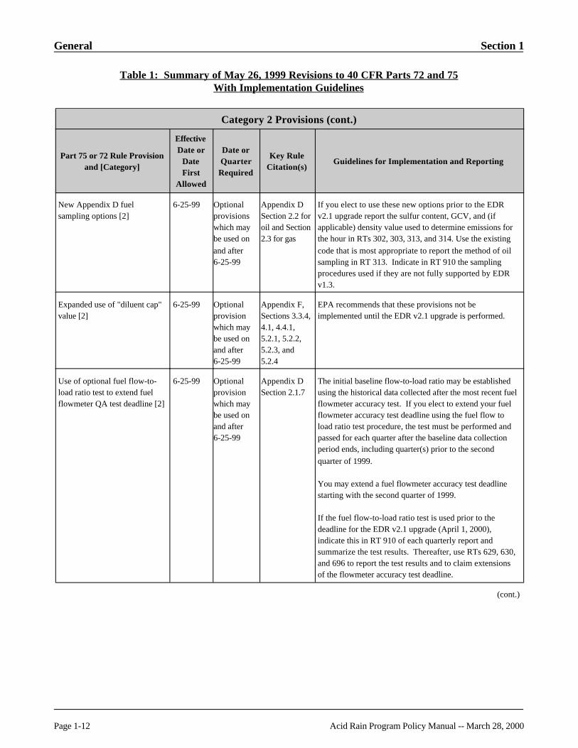
New Appendix D fuelsampling options [2]
6-25-99 Optionalprovisionswhich maybe used onand after 6-25-99
Appendix DSection 2.2 foroil and Section2.3 for gas
If you elect to use these new options prior to the EDRv2.1 upgrade report the sulfur content, GCV, and (ifapplicable) density value used to determine emissions forthe hour in RTs 302, 303, 313, and 314. Use the existingcode that is most appropriate to report the method of oilsampling in RT 313. Indicate in RT 910 the samplingprocedures used if they are not fully supported by EDRv1.3.
Expanded use of "diluent cap"value [2]
6-25-99 Optionalprovisionwhich maybe used onand after 6-25-99
Appendix F,Sections 3.3.4,4.1, 4.4.1, 5.2.1, 5.2.2,5.2.3, and5.2.4
EPA recommends that these provisions not beimplemented until the EDR v2.1 upgrade is performed.
Use of optional fuel flow-to-load ratio test to extend fuelflowmeter QA test deadline [2]
6-25-99 Optionalprovisionwhich maybe used onand after 6-25-99
Appendix DSection 2.1.7
The initial baseline flow-to-load ratio may be establishedusing the historical data collected after the most recent fuelflowmeter accuracy test. If you elect to extend your fuelflowmeter accuracy test deadline using the fuel flow toload ratio test procedure, the test must be performed andpassed for each quarter after the baseline data collectionperiod ends, including quarter(s) prior to the secondquarter of 1999.
You may extend a fuel flowmeter accuracy test deadlinestarting with the second quarter of 1999.
If the fuel flow-to-load ratio test is used prior to thedeadline for the EDR v2.1 upgrade (April 1, 2000),indicate this in RT 910 of each quarterly report andsummarize the test results. Thereafter, use RTs 629, 630,and 696 to report the test results and to claim extensionsof the flowmeter accuracy test deadline.
(cont.)

Section 1 General
Table 1: Summary of May 26, 1999 Revisions to 40 CFR Parts 72 and 75With Implementation Guidelines
Acid Rain Program Policy Manual -- March 28, 2000 Page 1-13
Category 3 Provisions
Part 75 or 72 Rule Provisionand [Category]
EffectiveDate or
DateFirst
Allowed
Date orQuarterRequired
Key RuleCitation(s)
Guidelines for Implementation and Reporting
General record keepingrequirements in § 75.57 through§ 75.59 [3]
6-25-99 4-01-00 or1-01-00,dependingon date ofDAHSupgrade toEDR v2.1
§ 75.57through§ 75.59
These recordkeeping provisions correspond to the requiredDAHS upgrade from EDR v1.3 to v2.1, with oneexception: if any new rule option is used prior to 4/1/00,the associated records in § 75.57 through § 75.59 must bekept on-site.
Otherwise, in the interval from 6/25/99 to 4/1/00 (or 1/1/00if the DAHS upgrade is done in the first quarter of 2000),the general recordkeeping provisions in § 75.54 through§ 75.56 remain in effect.
Reporting of SO2 emissionrates and heat input rates [3]
6-25-99 4-01-00 or1-01-00,dependingon date ofDAHSupgrade toEDR v2.1
§ 75.57(b)(5)and (c)(4)
Hourly reporting of SO2 emission rates (lb./hr) and heatinput rates (mmBtu/hr) is required. There was an error in§ 75.54(b)(5) of the previous version of Part 75. Insteadof requiring the heat input rate in mmBtu/hr, the rule haderroneously required total heat input in mmBtu. Also,there were misstatements in § 75.54(c)(3). Therequirement to report SO2 emissions in lb/hr was describedas mass emissions of SO2 rather than as an emission rate. Both of these errors have been corrected in the May 26,1999 final rule.
Quarterly stack flow-to-loadratio or gross heat rate test [3]
6-25-99 Secondquarter in2000
Appendix A,Sections 7.7and 7.8
Appendix B,Section 2.2.5
EPA encourages sources to begin performing the flow-to-load ratio test before the second quarter of 2000.
Prior to upgrading your DAHS to EDR v2.1 format reportflow-to-load ratio test results (pass/fail) in RT 910. Thereafter, report the test results in RT 605 and RT 606.
Electronic submittal ofquarterly reports [3]
6-25-99 First quarterin 2001
§ 75.64(f) Electronic submittal of quarterly reports is currentlyallowed and is the recommended method of submittingdata. Beginning on January 1, 2001, submittal through anelectronic modem or other approved method is required.
(cont.)

General Section 1
Table 1: Summary of May 26, 1999 Revisions to 40 CFR Parts 72 and 75With Implementation Guidelines
Page 1-14 Acid Rain Program Policy Manual -- March 28, 2000
Category 3 Provisions (cont.)
Part 75 or 72 Rule Provisionand [Category]
EffectiveDate or
DateFirst
Allowed
Date orQuarterRequired
Key RuleCitation(s)
Guidelines for Implementation and Reporting
Determination of the normalload level(s) and the two mostfrequently-used load levels [3]
6-25-99 Secondquarter in2000
Appendix A,Sections6.5.2.1 and7.6.5
Appendix B,Section 2.3.1.3
EPA recommends that these determinations be made assoon as possible after June 25, 1999, in order to ensurethat, in the interim period from 6/25/99 to 4/1/00: (1) gasmonitor RATAs are done at the "normal" load level, inaccordance with Section 6.5.2.1 of Appendix A andSection 2.3.1.3 of Appendix B; (2) 2-load annual flow RATAs are done at the two mostfrequently-used load levels, in accordance with Section6.5.2.1 of Appendix A and Section 2.3.1.3 of Appendix B;and (3) the bias adjustment factors for multi-load flowRATAs are determined in accordance with revised Section7.6.5 of Appendix A.
If the load level determinations are made prior to the EDRv2.1 upgrade, keep the required records of the historicaldata analysis and report the results of the data analysis inRT 910. Thereafter, report this information in RT 536.
Annual span/rangeevaluation [3]
6-25-99 12-31-99 Appendix A,Sections 2.1.1.5,2.1.2.5,2.1.3.3, and2.1.4.3
Perform the annual span and range evaluation required bythese provisions no later than 12-31-99 for the 1999calendar year and at least once in each subsequent year.
(cont.)

Section 1 General
Table 1: Summary of May 26, 1999 Revisions to 40 CFR Parts 72 and 75With Implementation Guidelines
Acid Rain Program Policy Manual -- March 28, 2000 Page 1-15
Category 4 Provisions
Part 75 or 72 Rule Provisionand [Category]
EffectiveDate or
DateFirst
Allowed
Date orQuarterRequired
Key RuleCitation(s)
Guidelines for Implementation and Reporting
New monitoring plan updatingprocedures [4]
6-25-99 1-01-00 § 75.53(b), (e),and (f)
§ 75.53(b) requires monitoring plans to be updatedwhenever changes are made to a monitoring system thataffect the information in the monitoring plan. EPA ismoving toward an all-electronic process for updatingmonitor plans. At the present time, the Agency is able toreceive electronic monitor plan updates in the quarterlyreport submittals, but not at other times.
EPA projects that by January 1, 2000, a mechanism willbe in place for receiving electronic monitor plan updates atall times. Until then, sources should continue to providehardcopy monitor plan updates to the States and Regionsand submit updated monitoring plan data in each quarterlyreport, as has been done in the past.
Use of EPA protocolcalibration gases that conformto the September, 1997protocol document, for dailycalibrations, linearity checksand reference methodtesting [4]
6-25-99 8-25-99 Appendix A, Section 5.1
As of June 25, 1999, the results of an EPA inquiry showedthat all major calibration gas suppliers were either usingthe 1997 protocol or would be using it within a few weeksof the effective date of the rule.
Therefore, calibration gases received or ordered prior toAugust 25, 1999 may be used until their expiration date. All gas cylinders ordered on and after August 25, 1999must meet the new protocol.
Use of maximum potentialconcentration of SO2, maximumpotential flow rate, ormaximum NOx emission ratewhen percent monitor dataavailability (PMA) is <80.0% [4]
6-25-99 4-01-00 § 75.33 Implementation of this provision is not required until thedeadline for upgrading to EDR v2.1 (April 1, 2000).
Use of this provision prior to the required EDR v2.1upgrade is allowed if the change is incorporated into theDAHS in an automated fashion and the proper MODCcode of 12 is used in RTs 200, 220, and 320. Manualentry of the MODC code is permitted.
Reporting of 200% of the rangefor a full-scale exceedance ofthe high range of an SO2
analyzer, NOx analyzer or flowmonitor [4]
6-25-99 4-01-00 Appendix A,Sections 2.1.1.5,2.1.2.5, and2.1.4.3
Implementation of the provision is not required until thedeadline for upgrading to EDR v2.1 (April 1 2000).
Use of this provision prior to the required EDR v2.1upgrade is allowed if the change is incorporated into theDAHS in an automated fashion and if the proper MODCcode of 20 is used. Manual entry of the MODC ispermitted.
(cont.)
General Section 1
Table 1: Summary of May 26, 1999 Revisions to 40 CFR Parts 72 and 75With Implementation Guidelines
Page 1-16 Acid Rain Program Policy Manual -- March 28, 2000
Category 4 Provisions (cont.)
Part 75 or 72 Rule Provisionand [Category]
EffectiveDate or
Date orQuarterRequired
Key RuleCitation(s)
Guidelines for Implementation and Reporting DateFirst Allowed
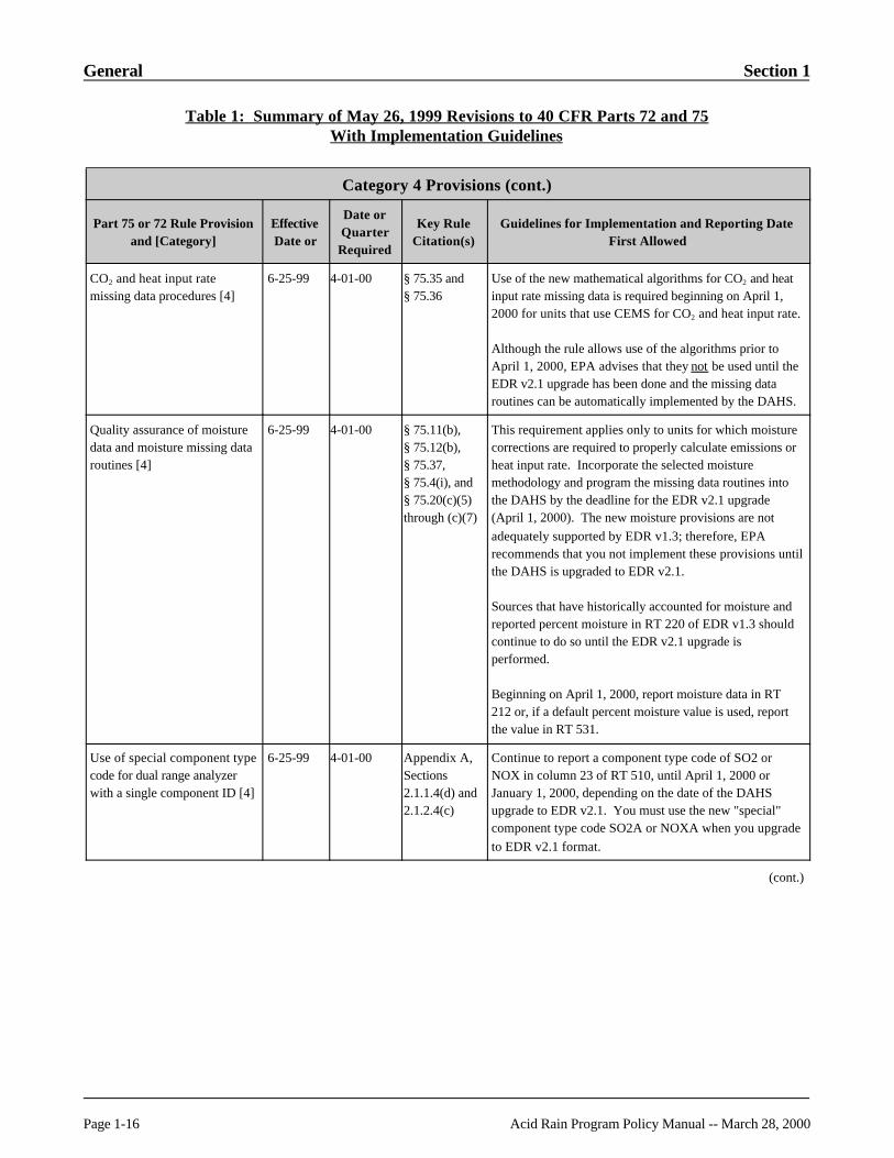
CO2 and heat input ratemissing data procedures [4]
6-25-99 4-01-00 § 75.35 and§ 75.36
Use of the new mathematical algorithms for CO2 and heatinput rate missing data is required beginning on April 1,2000 for units that use CEMS for CO2 and heat input rate.
Although the rule allows use of the algorithms prior toApril 1, 2000, EPA advises that they not be used until theEDR v2.1 upgrade has been done and the missing dataroutines can be automatically implemented by the DAHS.
Quality assurance of moisture data and moisture missing dataroutines [4]
6-25-99 4-01-00 § 75.11(b),§ 75.12(b),§ 75.37,§ 75.4(i), and§ 75.20(c)(5)through (c)(7)
This requirement applies only to units for which moisturecorrections are required to properly calculate emissions orheat input rate. Incorporate the selected moisturemethodology and program the missing data routines intothe DAHS by the deadline for the EDR v2.1 upgrade(April 1, 2000). The new moisture provisions are notadequately supported by EDR v1.3; therefore, EPArecommends that you not implement these provisions untilthe DAHS is upgraded to EDR v2.1.
Sources that have historically accounted for moisture andreported percent moisture in RT 220 of EDR v1.3 shouldcontinue to do so until the EDR v2.1 upgrade isperformed.
Beginning on April 1, 2000, report moisture data in RT212 or, if a default percent moisture value is used, reportthe value in RT 531.
Use of special component typecode for dual range analyzerwith a single component ID [4]
6-25-99 4-01-00 Appendix A,Sections2.1.1.4(d) and2.1.2.4(c)
Continue to report a component type code of SO2 orNOX in column 23 of RT 510, until April 1, 2000 orJanuary 1, 2000, depending on the date of the DAHSupgrade to EDR v2.1. You must use the new "special"component type code SO2A or NOXA when you upgradeto EDR v2.1 format.
(cont.)
Section 1 General
Table 1: Summary of May 26, 1999 Revisions to 40 CFR Parts 72 and 75With Implementation Guidelines
Acid Rain Program Policy Manual -- March 28, 2000 Page 1-17
Category 4 Provisions (cont.)
Part 75 or 72 Rule Provisionand [Category]
EffectiveDate or
Date orQuarterRequired
Key RuleCitation(s)
Guidelines for Implementation and Reporting DateFirst Allowed
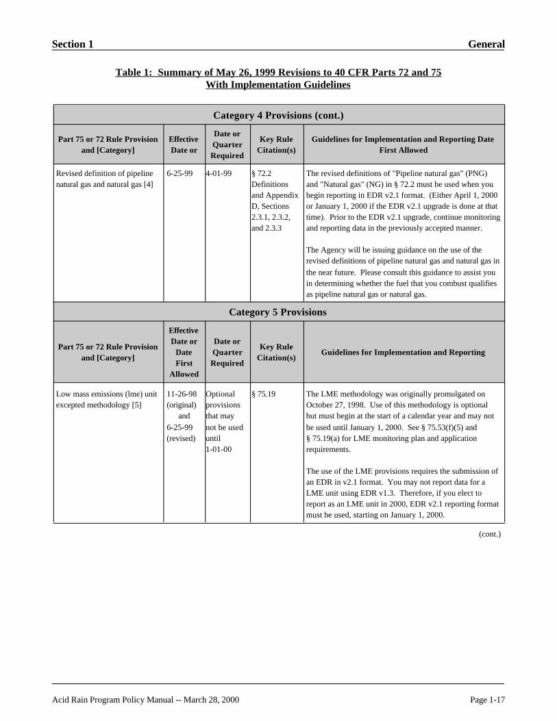
Revised definition of pipelinenatural gas and natural gas [4]
6-25-99 4-01-99 § 72.2Definitionsand AppendixD, Sections2.3.1, 2.3.2,and 2.3.3
The revised definitions of "Pipeline natural gas" (PNG)and "Natural gas" (NG) in § 72.2 must be used when youbegin reporting in EDR v2.1 format. (Either April 1, 2000or January 1, 2000 if the EDR v2.1 upgrade is done at thattime). Prior to the EDR v2.1 upgrade, continue monitoringand reporting data in the previously accepted manner.
The Agency will be issuing guidance on the use of therevised definitions of pipeline natural gas and natural gas inthe near future. Please consult this guidance to assist youin determining whether the fuel that you combust qualifiesas pipeline natural gas or natural gas.
Category 5 Provisions
Part 75 or 72 Rule Provisionand [Category]
EffectiveDate or
DateFirst
Allowed
Date orQuarterRequired
Key RuleCitation(s)
Guidelines for Implementation and Reporting
Low mass emissions (lme) unitexcepted methodology [5]
11-26-98(original)
and6-25-99(revised)
Optional provisionsthat maynot be useduntil1-01-00
§ 75.19 The LME methodology was originally promulgated onOctober 27, 1998. Use of this methodology is optionalbut must begin at the start of a calendar year and may notbe used until January 1, 2000. See § 75.53(f)(5) and§ 75.19(a) for LME monitoring plan and applicationrequirements.
The use of the LME provisions requires the submission ofan EDR in v2.1 format. You may not report data for aLME unit using EDR v1.3. Therefore, if you elect toreport as an LME unit in 2000, EDR v2.1 reporting formatmust be used, starting on January 1, 2000.
(cont.)

General Section 1
Table 1: Summary of May 26, 1999 Revisions to 40 CFR Parts 72 and 75With Implementation Guidelines
Page 1-18 Acid Rain Program Policy Manual -- March 28, 2000
Category 6 Provisions
Part 75 or 72 Rule Provisionand [Category]
EffectiveDate or
DateFirst
Allowed
Date orQuarterRequired
Key RuleCitation(s)
Guidelines for Implementation and Reporting
Requirement for a 4 monthwaiting time betweensuccessive RATAs removedfrom rule [6]
6-25-99 NA Removed fromAppendix B,Section 2.3.1
Successive RATAs performed on and after June 25, 1999may be separated by fewer than 4 months.
Requirement for a 2 monthwaiting time betweensuccessive linearity checksremoved from rule [6]
6-25-99 NA Appendix Bsection 2.2.1
On and after June 25, 1999, the minimum waiting timebetween successive linearity tests has been reduced to 30days, "to the extent practicable."
Quarterly reports for"deferred" Acid Rain units (i.e.,existing affected units that wereshut down on the applicablecompliance deadline in§ 75.4(d), and have neveroperated since) need not besubmitted until the unit re-commences commercialoperation [6]
6-25-99 NA § 75.64(a)
Owners and operators should discontinue the submittal ofabbreviated EDR reports for deferred units, starting withthe second calendar quarter of 1999.
Restriction to two RATAattempts to obtain an annualfrequency or favorable BAFremoved from rule [6]
6-25-99 NA Appendix BSection 2.3.1.4
On and after June 25, 1999, you may perform as manyRATAs as are deemed necessary to obtain an annualRATA frequency or a more favorable BAF.
Requirement to perform annualconcurrent flow and SO2 RATAs removed from rule [6]
6-25-99 NA Removed fromAppendix A,Section 6.5
As of June 25, 1999, SO2 and flow RATAs need not beperformed concurrently at normal load.
Submittal of reasons formissing data in RT 550 [6]
6-25-99 NA § 75.54(g) and§ 75.57(h)
Beginning with the quarterly report for the third quarter of1999, submission of this record type is optional.
Requirement to maintain an on-site spare parts inventoryremoved from rule [6]
6-25-99 NA Removed fromAppendix BSection 1.3
Maintenance of an on-site spare parts inventory is nolonger required, as of June 25, 1999.
References: N/A

Section 1 General
Acid Rain Program Policy Manual -- March 28, 2000 Page 1-19
Key Words: Electronic data reporting, Electronic report formats, Reporting
History: First published in October 1999 Revised Manual
Question 1.13
Topic: Policy Manual Updates
Question: Are past Policy Manual updates still valid?
Answer: Yes, but only if the particular question is in the Revised Policy Manual (dated October14, 1999). The Revised Policy Manual includes all old questions (including thosedistributed through updates) that are still valid for policy purposes. Most questionshave been revised, so you should reread the answers and make certain the substanceis unchanged.
References: N/A
Key Words: N/A
History: First published in March 2000, Update #12
Question 1.14
Topic: Audit Checklist
Question: Is EPA planning on revising the Level 2 audit checklist which is included in the AcidRain CEMS Field Audit Manual and used when conducting field audits?
Answer: Not at this time. For items that are not applicable following the Part 75 revisions, youmay just put "N/A" on the form. You should make sure you are using the latest versionof the form, available from the web site. You may also alter the format if you choose.
References: N/A
Key Words: N/A
History: First published in March 2000, Update #12

General Section 1
Page 1-20 Acid Rain Program Policy Manual -- March 28, 2000
Question 1.15
Topic: PEMS
Question: Is EPA considering allowing the use of PEMS?
Answer: EPA is conducting a PEMS study. The Agency has done some preliminarybackground work, but extensive field tests are needed to determine whether PEMSshould be allowed to be used under the Acid Rain Program or Subpart H.
References: N/A
Key Words: Predictive emissions monitoring systems
History: First published in March 2000, Update #12
Question 1.16
Topic: Exemptions From Part 60 Requirements
Question: My facility is subject to continuous monitoring requirements under both 40 CFR Part60 and 40 CFR Part 75. The May 26, 1999 revisions to Part 75 allow us to claim anexemption from linearity testing of our gas monitors for quarters in which the unitoperates for fewer than 168 hours. May I obtain a similar exemption from the Part 60,Appendix F quality assurance provisions for quarterly cylinder gas audits (which aresimilar to Part 75 linearity checks) for quarters in which the unit operates for fewerthan 168 hours?
Answer: You may only obtain an exemption from the Part 60 cylinder gas audit (CGA)requirement if the permitting authority allows it. When a source is regulated underdifferent programs with similar rule provisions (in this case, linearity checks andcylinder gas audits), the facility must comply with each of these rule provisionsseparately, unless the regulatory agency allows exceptions to this. Therefore, unlessthe permitting authority in the region or state stipulates otherwise, you would have tofollow the procedures of Part 60, Appendix F, which require quarterly cylinder gasaudits, even for quarters in which the unit operates for fewer than 168 hours.
References: 40 CFR Part 60, Appendix F; 40 CFR Part 75, Appendix B, Section 2.2.3(f)

Section 1 General
Acid Rain Program Policy Manual -- March 28, 2000 Page 1-21
Key Words: Quality assurance
History: First published in March 2000, Update #12
Question 1.17
Topic: Rule Revisions and OTC NBP Sources
Question: My source is an OTC NOx Budget Program (NBP) source and is not subject to theAcid Rain Program. Can we take advantage of some of the new Part 75 rule revisionsthat were promulgated on May 26, 1999?
Answer: You may only use the new Part 75 rule provisions if :
(1) Your State permits use of the revised rule; and
(2) The EDR version in which you report data (i.e., v.2.0 or v.2.1) is consistent withthe new Part 75 provision(s) that you intend to use.
The best way to ensure that condition (2) above is met is to fully implement the NOx
mass emissions provisions of Subpart H of Part 75 (see §§ 75.70 through 75.75). Note that if you choose this option, you may no longer use any monitoring or reportingoption allowed by the January, 1997 NOx Budget Program Guidance, if the option isnot allowed under Part 75. You must also upgrade your DAHS software from EDRv2.0 to EDR v2.1.
If you want to implement some, but not all, of the new Part 75 provisions and wish tocontinue reporting in EDR v2.0, you must petition your State for permission to do so. EPA advises States to use discretion in granting such petitions. As a general guideline,petitions are considered approvable if the rule provisions that the source is requestingpermission to use are consistent with EDR v2.0 reporting. However, if implementationof the new rule provisions requires any of the new record types or new data fieldsassociated with EDR v2.1, the State should carefully assess the potential impact of notreceiving the extra information that EDR v2.1 would provide. If the State considersthe impact of not receiving that information to be minimal, or if the State and the facilitycan agree upon an alternative way of documenting compliance with the new ruleprovisions (e.g., use of EDR RT 910, the electronic cover letter), then the petition maybe approved.
Note that regardless of whether the State approves any such petitions, NOx Budgetsources must report all required data in a single EDR version. You may not report in a
General Section 1
Page 1-22 Acid Rain Program Policy Manual -- March 28, 2000
format consisting of EDR v2.0 with a few v2.1 records added on, nor may you reportin EDR v2.1 with a few v2.0 records added on.
The Clean Air Markets Division will issue written guidance to the States to assist themin evaluating the types of petitions described in the previous paragraphs. Until thatguidance is finalized, States receiving such petitions should make case-by-casedeterminations and should contact EPA if any questions or issues arise.
References: N/A
Key Words: Applicability
History: First published in March 2000, Update #12
Acid Rain Program Policy Manual -- March 28, 2000 Page 2-i
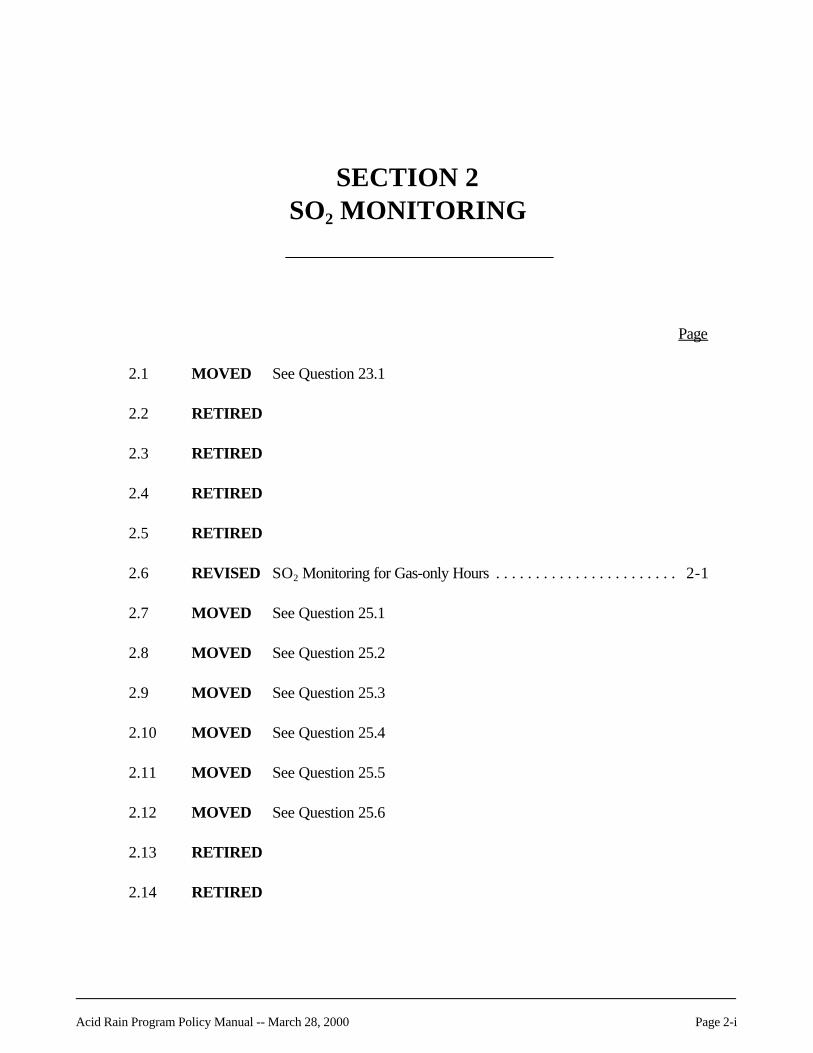
SECTION 2SO2 MONITORING
Page
2.1 MOVED See Question 23.1
2.2 RETIRED
2.3 RETIRED
2.4 RETIRED
2.5 RETIRED
2.6 REVISED SO2 Monitoring for Gas-only Hours . . . . . . . . . . . . . . . . . . . . . . . 2-1
2.7 MOVED See Question 25.1
2.8 MOVED See Question 25.2
2.9 MOVED See Question 25.3
2.10 MOVED See Question 25.4
2.11 MOVED See Question 25.5
2.12 MOVED See Question 25.6
2.13 RETIRED
2.14 RETIRED

SO2 Monitoring Section 2
Page 2-ii Acid Rain Program Policy Manual -- March 28, 2000
Page
2.15 RETIRED
2.16 Use of Default SO2 Value . . . . . . . . . . . . . . . . . . . . . . . . . . . . . . . . . . . . . . . . . 2-4
Section 2 SO2 Monitoring
Acid Rain Program Policy Manual -- March 28, 2000 Page 2-1
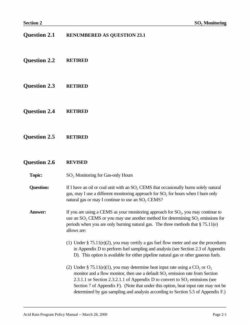
Question 2.1 RENUMBERED AS QUESTION 23.1
Question 2.2 RETIRED
Question 2.3 RETIRED
Question 2.4 RETIRED
Question 2.5 RETIRED
Question 2.6 REVISED
Topic: SO2 Monitoring for Gas-only Hours
Question: If I have an oil or coal unit with an SO2 CEMS that occasionally burns solely naturalgas, may I use a different monitoring approach for SO2 for hours when I burn onlynatural gas or may I continue to use an SO2 CEMS?
Answer: If you are using a CEMS as your monitoring approach for SO2, you may continue touse an SO2 CEMS or you may use another method for determining SO2 emissions forperiods when you are only burning natural gas. The three methods that § 75.11(e)allows are:
(1) Under § 75.11(e)(2), you may certify a gas fuel flow meter and use the proceduresin Appendix D to perform fuel sampling and analysis (see Section 2.3 of AppendixD). This option is available for either pipeline natural gas or other gaseous fuels.
(2) Under § 75.11(e)(1), you may determine heat input rate using a CO2 or O2
monitor and a flow monitor, then use a default SO2 emission rate from Section2.3.1.1 or Section 2.3.2.1.1 of Appendix D to convert to SO2 emissions (seeSection 7 of Appendix F). (Note that under this option, heat input rate may not bedetermined by gas sampling and analysis according to Section 5.5 of Appendix F.)

SO2 Monitoring Section 2
Page 2-2 Acid Rain Program Policy Manual -- March 28, 2000
Eh ' ER × HI
This option is available only for fuels that qualify as either pipeline natural gas ornatural gas (as defined in § 72.2).
To report heat input data using a CO2 or O2 monitor and a flow monitor, it is notnecessary to define and certify a separate system to calculate heat input. The flowsystem and CO2 system must be certified under Part 75 before using the flow orCO2 data.
To report SO2 data for pipeline natural gas or natural gas for these hours, reportthe SO2 mass emissions in RT 310. Leave blank the value for unadjusted SO2
mass emissions. The formula you should use to determine SO2 emissions isEquation F-23 from Appendix F, Section 7:
Where:
Eh = Hourly SO2 mass emission rate, lb/hr.ER = Default SO2 emission rate, either 0.0006 for pipeline natural gas or calculated
using Equation D-1h, for "natural gas."HI = Hourly heat input rate (using bias-adjusted flow rate), mmBtu/hr.
This formula should be included in RT 520 of your monitoring plan, and identifiedas "F-23" in the formula code column.
For any hour in which this formula is used to calculate SO2 mass emissions, do notreport a RT 200. However, you must provide sufficient hourly data to support theheat input rate determination (i.e., report the stack gas flow rate in RT 220 andthe diluent gas concentration, either in RTs 202 and 210 (if CO2 concentration isused to calculate heat input rate) or in RT 211 (if heat input rate is calculated usingO2 concentration).
(3) Under § 75.11(e)(3) you may use the SO2 monitor during the combustion ofgaseous fuel. However, you must report a default value of 2.0 ppm SO2 wheneververy low sulfur gaseous fuel (as defined in § 72.2) is combusted and the bias-adjusted SO2 hourly average value recorded by the CEMS is less than 2.0 ppm.
Periods when only gaseous fuel is burned are not used to determine the monitordata availability for SO2 when using either method (1) or (2) described above. Inaddition, the standard SO2 missing data procedures are used if the SO2 CEMSwill be used to report data. The standard missing data procedures are not used inperiods when only gaseous fuel is being combusted when using either method (1)or (2) described above. Rather, if you are using a fuel flow meter to determineSO2 emissions, use the missing data procedures outlined in Appendix D. If you

Section 2 SO2 Monitoring
Acid Rain Program Policy Manual -- March 28, 2000 Page 2-3
are determining heat input rate by using a flow monitor and a CO2 or O2 monitor,use the specific missing data procedures for those parameters.
References: § 75.11(e), § 75.64; Appendix D, Section 2.3; Appendix F, Section 7
Key Words: Electronic reporting formats, Reporting, SO2 monitoring
History: First published in March 1995, Update #5; revised July 1995, Update #6; revisedMarch 1996, Update #8; revised in October 1999 Revised Manual
Question 2.7 RENUMBERED AS QUESTION 25.1
Question 2.8 RENUMBERED AS QUESTION 25.2
Question 2.9 RENUMBERED AS QUESTION 25.3
Question 2.10 RENUMBERED AS QUESTION 25.4
Question 2.11 RENUMBERED AS QUESTION 25.5
Question 2.12 RENUMBERED AS QUESTION 25.6
Question 2.13 RETIRED
Question 2.14 RETIRED

SO2 Monitoring Section 2
Page 2-4 Acid Rain Program Policy Manual -- March 28, 2000
Question 2.15 RETIRED
Question 2.16 REVISED
Topic: Use of Default SO2 Value
Question: I have a coal-fired unit with certified SO2 and flow monitoring systems. The unitoccasionally fires gaseous fuel. According to § 75.11(e)(3)(iii), the DAHS mustautomatically substitute a 2.0 ppm default for hours when: (a) the unit is combustinggaseous fuel that meets the definition of "very low sulfur fuel" in § 72.2; and (b) themeasured SO2 concentration reading is less than 2.0 ppm. Does EPA require me todemonstrate that my gaseous fuel qualifies as very low sulfur fuel before I use the 2.0ppm default value?
Answer: No demonstration is required. The definition of very low sulfur fuel in § 72.2 includesthe following: "pipeline natural gas" (as defined in § 72.2), "natural gas" (as defined in§ 72.2), and any other gaseous fuel which has 20 grains or less of total sulfur. If,based on a knowledge of the composition of the gaseous fuel being combusted (e.g.,from contract specifications or historical fuel sampling information), you believe the fuelqualifies as very low sulfur fuel, report the 2.0 ppm default SO2 concentration for gas-fired hours when the bias-adjusted SO2 concentration is less than 2.0 ppm.
References: § 72.2, § 75.11(e)(3)(iii)
Key Words: SO2 monitoring, Reporting
History: First published in March 2000, Update #12

Acid Rain Program Policy Manual -- March 28, 2000 Page 3-i
SECTION 3FLOW MONITORING
Page
3.1 RETIRED
3.2 REVISED Applicability . . . . . . . . . . . . . . . . . . . . . . . . . . . . . . . . . . . . . . . . . 3-1
3.3 Requirements for Dual Flow (X-Pattern Flow) Monitoring Systems . . . . . . . . . . 3-1
3.4 REVISED Length of Reference Method 2 Test Runs . . . . . . . . . . . . . . . . . . . 3-3
3.5 Flow Monitor Interference Check . . . . . . . . . . . . . . . . . . . . . . . . . . . . . . . . . . . 3-3
3.6 REVISED Accuracy of Flow Monitoring and Reference Methods . . . . . . . . . 3-4
3.7 REVISED Accuracy of Flow Monitoring and Reference Methods . . . . . . . . . 3-5
3.8 REVISED Interference Checks when Unit is Operating . . . . . . . . . . . . . . . . . 3-6
3.9 Interference Checks on Differential Pressure Flow Monitors . . . . . . . . . . . . . . . 3-6
3.10 Moisture Content Determination . . . . . . . . . . . . . . . . . . . . . . . . . . . . . . . . . . . . 3-7
3.11 MOVED See Question 25.7
3.12 Re-linearization of Flow Monitor During Pre-RATA Testing . . . . . . . . . . . . . . . 3-8
3.13 Test Methods 2F, 2G, and 2H -- Application . . . . . . . . . . . . . . . . . . . . . . . . . . 3-8
3.14 Test Method 2H -- Applying the Default Wall Effects Adjustment Factor(WAF) . . . . . . . . . . . . . . . . . . . . . . . . . . . . . . . . . . . . . . . . . . . . . . . . . . . . . . . 3-9
3.15 Test Method 2H -- Minimum Acceptable Calculated Wall Effects Adjustment Factor (WAF) . . . . . . . . . . . . . . . . . . . . . . . . . . . . . . . . . . . . . . . 3-10

Flow Monitoring Section 3
Page 3-ii Acid Rain Program Policy Manual -- March 28, 2000
Page
3.16 Test Method 2H -- Frequency of Performing Wall Effects Testing . . . . . . . . . . 3-11
3.17 Test Method 2H -- Wall Effects Adjustment Factors (WAFs) and Load Levels . . . . . . . . . . . . . . . . . . . . . . . . . . . . . . . . . . . . . . . . . . . . . . . . . . 3-11
3.18 Test Method 2H -- Discarding Wall Effects Adjustment Factors (WAFs) . . . . 3-12
3.19 Test Method 2, 2F, 2G, and 2H - Determining Wall Effects AdjustmentFactors (WAFs) as Part of the RATA . . . . . . . . . . . . . . . . . . . . . . . . . . . . . . 3-12
3.20 Test Method 2, 2F, and 2G - Using Different Test Methodsat Different Load Levels . . . . . . . . . . . . . . . . . . . . . . . . . . . . . . . . . . . . . . . . 3-13
3.21 Test Method 2H - Applicability of Notes Regarding StackDiameters in Sections 8.2.3(b) and 8.2.3(c) . . . . . . . . . . . . . . . . . . . . . . . . . 3-14
3.22 Test Method 2H - Typographical Error in Headers of Columns D and Eof Form 2H-2 . . . . . . . . . . . . . . . . . . . . . . . . . . . . . . . . . . . . . . . . . . . . . . . 3-14
3.23 Test Method 2H - Using Default Wall Effects Adjustment Factor (WAF)After Deriving a Calculated WAF . . . . . . . . . . . . . . . . . . . . . . . . . . . . . . . . . . 3-15
3.24 Stack Flow-to-load Test . . . . . . . . . . . . . . . . . . . . . . . . . . . . . . . . . . . . . . . . 3-16
3.25 Hourly Averages for Abbreviated Flow-to-load Test . . . . . . . . . . . . . . . . . . . . 3-16
3.26 Test Method 2H -- Restrictions on Use of Default Wall Effects Adjustment Factors (WAFs) . . . . . . . . . . . . . . . . . . . . . . . . . . . . 3-17
3.27 Test Method 2H -- Qualification for Default Value . . . . . . . . . . . . . . . . . . . . . 3-18
3.28 Test Method 2H -- Gunite Stack . . . . . . . . . . . . . . . . . . . . . . . . . . . . . . . . . . 3-18
3.29 Use of Spherical Probes for Flow Test Methods . . . . . . . . . . . . . . . . . . . . . . . 3-18
3.30 Calibration of Probe . . . . . . . . . . . . . . . . . . . . . . . . . . . . . . . . . . . . . . . . . . . . 3-19
3.31 Use of 3D Probe for Methods 2F and 2H . . . . . . . . . . . . . . . . . . . . . . . . . . . . 3-20
Section 3 Flow Monitoring
Acid Rain Program Policy Manual -- March 28, 2000 Page 3-iii
Page
3.32 Use of WAF for Square and Rectangular Stacks . . . . . . . . . . . . . . . . . . . . . . . 3-20
3.33 Test Method 2H -- Traverse Points . . . . . . . . . . . . . . . . . . . . . . . . . . . . . . . . 3-20
3.34 Minimum WAF . . . . . . . . . . . . . . . . . . . . . . . . . . . . . . . . . . . . . . . . . . . . . . . 3-21
3.35 Test Methods 2 and 2H . . . . . . . . . . . . . . . . . . . . . . . . . . . . . . . . . . . . . . . . . 3-22

Flow Monitoring Section 3
Page 3-iv Acid Rain Program Policy Manual -- March 28, 2000
[This page intentionally left blank.]

Section 3 Flow Monitoring
Acid Rain Program Policy Manual -- March 28, 2000 Page 3-1
Question 3.1 RETIRED
Question 3.2 REVISED
Topic: Applicability
Question: Is a flue gas volumetric flow monitor required on a gas-fired or oil-fired unit?
Answer: A gas-fired unit or oil-fired unit subject to the Acid Rain Program does not need a fluegas volumetric flow monitor if the owner or operator reports SO2 mass emissions usingthe procedures specified in Appendix D or uses the low mass emissions (LME)methodology in § 75.19. Gas-fired and oil-fired units subject to Subpart H also haveoptions for monitoring NOx mass that do not require flow CEMS. These are outlinedin § 75.71.
References: § 75.11(d)(2), § 75.19, § 75.71; Appendix D
Key Words: Excepted methods, Flow monitoring
History: First published in Original March 1993 Policy Manual; revised in October 1999Revised Manual
Question 3.3
Topic: Requirements for Dual Flow (X-Pattern Flow) Monitoring Systems
Question: A number of sources have installed two sets of flow monitors in a single stack and arereporting the average flow value as the unit flow on an hourly basis. This includessystems using x-pattern ultrasonic monitors, as well as systems using two differentialpressure monitors.
How should these sources represent these monitors in the monitoring plan? Howshould they report flow data and calibration records?
Answer: In the monitoring plan, identify each separate flow monitor as a component in theprimary flow system. If each monitor alone will be used as a redundant backup flowsystem, also define each redundant backup system containing a single flow monitor.

Flow Monitoring Section 3
Page 3-2 Acid Rain Program Policy Manual -- March 28, 2000
For example, a utility may install flow monitors Component 00A and Component 00Bon a single stack. The average flow value of Component 00A and 00B is identifiedwith primary System P01. Component 00A is also a component of redundant backupSystem B01, and Component 00B is a component of redundant backup System B02.
When the primary system is used to report data, report one set of calibration andinterference records for each flow monitor component of the primary system. Reportthe average hourly flow value in RT 220 using only the system ID. Leave thecomponent ID blank. EPA will recognize the blank component ID as an indicationthat the system contains more than one flow monitor component and will evaluate themonitoring plan data for the multiple components and the calibration and interferencecheck data for appropriate multiple QA records.
For certification purposes and ongoing quality assurance, compare the referencemethod results to the DAHS read out for each single flow monitor and the primaryflow system comprised of the average of its two components. Report three sets ofRATA and bias test data and results: one for system P01 (the average of components00A and 00B), one for system B01, and one for system B02.
Conduct a 7-day calibration error test on each single flow monitor component. Youmust report the 7-day calibration error test data and results once for each backupsystem and again for each flow monitor component of the primary system. Forexample, you would report the 7-day calibration error test data and results for eachflow monitor component of the primary system: 00A-P01, 00B-P01, and again foreach of the two backup systems: 00A-B01, and 00B-B02. The flow quarterly leakcheck results would be handled in the same manner as the 7-day calibration error test.
On any particular day for which data is reported from a backup flow system, you mustreport the daily calibration error and interference check using the backup componentID and system ID. If both primary and backup flow systems are used in the same day,calibration error and interference check data and results should be reported once foreach flow monitor component of the primary system (00A-P01 and 00B-P01) andagain for the component of the backup system used (e.g., 00A-B01).
References: Appendix A
Key Words: Flow monitoring, Monitoring plan, Reporting
History: First published in March 1995, Update #5
Section 3 Flow Monitoring
Acid Rain Program Policy Manual -- March 28, 2000 Page 3-3
Question 3.4 REVISED
Topic: Length of Reference Method 2 Test Runs
Question: Must a Method 2 flow run be 30 to 60 minutes long?
Answer: No. Method 2 only requires a run to be long enough to obtain a stable reading at eachtraverse point. The EPA recommends that flow run times be consistent with the runtime for a gas RATA run (21 minutes). Flow runs shorter than 21 minutes areacceptable, but runs must be at least 5 minutes long.
References: 40 CFR Part 60, Appendix A (RM 2); 40 CFR Part 75, Appendix A, Section 6.5.7
Key Words: Flow monitoring, Reference methods
History: First published in July 1995, Update #6; revised in October 1999 Revised Manual
Question 3.5
Topic: Flow Monitor Interference Check
Question: Must quarterly reports include daily interference check results for stack gas flowmonitors, regardless of type of flow monitor?
Answer: Yes. Part 75, Appendix A, Section 2.2.2.2 details the interference checkrequirements for three types of flow monitors. The EPA has received questionsspecifically asking whether ultrasonic flow monitors must perform the interferencecheck. For ultrasonic flow monitors, as well as thermal and differential pressure flowmonitors, you must perform the daily interference check. For example, for anultrasonic flow monitoring system you would record a daily (or more frequent)interference check pass in RT 231 based on a sensor that indicates that the transducerpurge air is working correctly. Conversely, a fail would be recorded in the event thatthe transducer purge air is not working correctly.
References: Appendix A, Section 2.2.2.2
Key Words: Flow monitoring, QA/QC, Reporting
History: First published in July 1995, Update #6
Flow Monitoring Section 3
Page 3-4 Acid Rain Program Policy Manual -- March 28, 2000
Question 3.6 REVISED
Topic: Accuracy of Flow Monitoring and Reference Methods
Question: Are the SO2 emissions data reported under the Acid Rain Program high due toinaccuracy in the reference method for volumetric flow (EPA Test Method 2)? If it isuncertain, what is EPA doing to resolve the issue?
Answer: The evidence amassed to date does not indicate a clearly consistent pattern. Claims ofoverestimation are counterbalanced by evidence of little or no overestimation. Theresults appear to be highly dependent on site-specific flow patterns, particularlywhether the emission flow is axial, going straight out the stack, or off-axial (i.e., swirlingout the stack).
In addition, many of the claims appear to be based on a comparison between flowrates derived from fuel factors and fuel sampling-based heat input and flow ratesderived from continuous emission monitoring systems (CEMS) as required by Part 75. Concluding that SO2 measurements are incorrect because the monitored flow rates arehigher than the fuel-factor-derived flow rates is questionable.
The frequency of measurement (hourly) and quality assurance (daily) is generally muchhigher with the Acid Rain certified CEMS than with fuel sampling. Estimating flowover short periods of time from fuel factors and heat input also depends on a highdegree of consistency in the fuel supply, which is rarely the case at coal-fired boilers.
In response to the concerns of the regulated community and because of the importanceof accurate emission measurements for environmental protection, and for the effectiveoperation of the SO2 allowance market, EPA developed three new test methods(Reference Methods 2F, 2G, and 2H) for measuring volumetric flow. These new testmethods were published in the Federal Register and became effective on July 13,1999.
Method 2F measures the axial velocity, taking into account both the yaw and pitchangles, using a 3-dimensional probe, such as a prism-shaped, five-hole probe(commonly called a DA or DAT probe) or a five-hole spherical probe.
Method 2G is a variant of existing Method 2, which uses a Type S pitot tube or a 3-dimensional probe to determine the flue gas velocity in a stack or duct, taking intoaccount the yaw angle of flow. Method 2G does not account for the pitch angle offlow.
In a stack or duct with flowing gas, the gas velocity will approach zero near the stackor duct wall. Method 2H can be used in conjunction with existing Method 2 or new

Section 3 Flow Monitoring
Acid Rain Program Policy Manual -- March 28, 2000 Page 3-5
Methods 2F or 2G to account for this velocity drop-off when determining volumetricflow rate.
Questions 3.13 through 3.23 in this manual provide implementation guidelines for thenew flow methods. If additional questions arise concerning these new methods, EPAwill add further questions and answers to Section 3, as appropriate.
References: 40 CFR Part 60, Appendix A (RMs 2, 2F, 2G, and 2H)
Key Words: Flow monitoring, Reference methods
History: First published in November 1995, Update #7; revised in October 1999 RevisedManual
Question 3.7 REVISED
Topic: Accuracy of Flow Monitoring and Reference Methods
Question: Will adjustments be made to my reported SO2 emissions from previous years once thethree new flow test methods are effective?
Answer: No. The Acid Rain regulations require relative accuracy test audits (RATAs) to beperformed using the appropriate test method that is in effect at the time of RATAtesting. Prior to July 13, 1999, Method 2 was the specified reference method for flowrate RATAs. However, on May 14, 1999, three new test methods for measuringvolumetric flow rate (Methods 2F, 2G, and 2H) were published in the FederalRegister and became effective on July 13, 1999. On and after the effective date, thesenew test methods may be used to re-characterize flow monitors and to perform flowRATAs. Retroactive adjustment of SO2 emission data reported prior to that date willnot be allowed, however. Implementation guidelines for the new flow methods aregiven in Questions 3.13 through 3.23, below.
References: 40 CFR Part 60, Appendix A (RMs 2, 2F, 2G, and 2H)
Key Words: Flow monitoring, Reference methods
History: First published in November 1995, Update #7; revised in October 1999 RevisedManual

Flow Monitoring Section 3
Page 3-6 Acid Rain Program Policy Manual -- March 28, 2000
Question 3.8 REVISED
Topic: Interference Checks when Unit is Operating
Question: Must interference checks be performed when the unit is operating?
Answer: Yes. Appendix A, Section 2.2.2.2 requires a utility to demonstrate non-interferencefrom moisture, and to perform a daily test to detect pluggage and/or malfunction ofeach resistance temperature device (RTD), transceiver or equivalent. Flow monitorscommonly employ a purge across the transceiver or out the sampling ports or periodicheating of RTDs to meet the above requirements. Because all of these are activemeasures utilizing mechanical/electrical devices, they may be susceptible to changes intemperature and pressure observed during unit operation. Therefore, the interferencecheck should be performed during unit operation.
References: Appendix A, Section 2.2.2.2; Appendix B, Section 2.1.2
Key Words: Flow monitoring, QA/QC, Reporting
History: First published in November 1995, Update #7; revised in October 1999 RevisedManual
Question 3.9
Topic: Interference Checks on Differential Pressure Flow Monitors
Question: Must interference checks performed on differential pressure flow monitors be capableof detecting pluggage during a purge?
Answer: Part 75, Appendix A, Section 2.2.2.2 states in part: "Design and equip each flowmonitor with a means to detect, on at least a daily basis, pluggage of each sample lineand sensing port. . . ." Because differential pressure flow monitor purge cycles aregenerally performed at least daily, performing the interference check during the purgemay make sense. Regardless of whether the interference check is performed during apurge, the interference check must be performed so that any pluggage is detected andreported at least daily. In practice, this means that if no pluggage of any sample line orsensing port is present, a passed interference check would be reported; if pluggage ispresent, a failed interference check would be reported. Also, please refer to Question3.5.
References: Appendix A, Section 2.2.2.2

Section 3 Flow Monitoring
Acid Rain Program Policy Manual -- March 28, 2000 Page 3-7
Key Words: Flow monitoring, QA/QC, Reporting
History: First published in November 1995, Update #7
Question 3.10
Topic: Moisture Content Determination
Question: My pollutant concentration is measured on a dry basis and the flow rate is measuredon a wet basis. Can I use the wet bulb-dry bulb technique to determine the moisturecontent of the stack gases?
Answer: It depends upon the use of the moisture data. The wet bulb-dry bulb technique maynot be used when converting dry pollutant concentration to a wet basis for thecalculation of pollutant emission rate. Either Reference Method 4 in Appendix A of 40CFR Part 60 or the approximation method described in Section 3 of Method 4(midget impinger technique) must be used to convert gas concentrations from a dry towet basis. A 1978 EPA field study has demonstrated that the midget impingertechnique is capable of giving results within 1% H2O of the reference method (seeReference 2 in the Bibliography of Reference Method 6A).
Method 4 allows the use of other approximation methods, such as the wet bulb-drybulb technique to provide estimates of percent moisture to aid in setting isokineticsampling rates prior to a pollutant emission measurement run. For the Acid RainProgram, you may use the wet bulb-dry bulb technique when determining themolecular weight of the stack gas for the purpose of calculating the stack gasvolumetric flow rate.
References: 40 CFR Part 60, Appendix A (RM 4)
Key Words: Flow monitoring, Reference methods
History: First published in March 1996, Update #8
Question 3.11 RENUMBERED AS QUESTION 25.7

Flow Monitoring Section 3
Page 3-8 Acid Rain Program Policy Manual -- March 28, 2000
Question 3.12
Topic: Re-linearization of Flow Monitor During Pre-RATA Testing
Question: If a flow monitor is re-characterized or re-linearized during pre-RATA testing, do weneed to use missing data for flow between the time the flow monitor was re-characterized and the time it passes the RATA?
Answer: Not necessarily. According to Section 2.3.2(b)(3) of Appendix B, you have two datavalidation options following a major adjustment or re-linearization of a flow monitor: (1) invalidate all data from the monitor from the hour of the re-linearization of theinstrument until a subsequent hands-off RATA is passed; or (2) invalidate data fromthe monitor from the hour of the re-linearization of the instrument until a subsequentprobationary calibration error test is passed and then use the conditional datavalidation procedures of § 75.20(b)(3). When the second option is chosen, if thesubsequent RATA is passed hands-off, data from the monitor are considered quality-assured, back to the time of completion of the probationary calibration error test.
References: § 75.20(b)(3); Appendix B, Section 2.3.2(b)(3)
Key Words: Flow monitoring, Diagnostic testing, RATAs
History: First published in October 1999 Revised Manual
Question 3.13
Topic: Test Methods 2F, 2G, and 2H -- Application
Question: Once new Test Methods 2F, 2G, and 2H become effective on July 13, 1999, how doI implement them? In particular, what adjustments can be made to the flow monitor inpreparation for performing a RATA using Methods 2F, 2G, and 2H?
Answer: The recommended procedures for implementing the new flow rate methods are asfollows:
(1) First, decide which flow reference method or combination of methods will beimplemented (e.g., Methods 2 and 2H with a default wall adjustment factor(WAF), Methods 2F and 2H with a calculated WAF, etc.).
(2) Second, perform whatever diagnostic testing and wall effects measurements arenecessary to establish new parameter values or to adjust existing parameter values
Section 3 Flow Monitoring
Acid Rain Program Policy Manual -- March 28, 2000 Page 3-9
that will be programmed into the flow monitor to make the monitor readings agreewith the selected reference method(s). (This process is analogous to the set-up orcharacterization of the flow monitor that was done prior to initial certification, tomake the monitor readings agree with Method 2.) If Method 2F or 2G is selectedas a reference method, establish the new parameter values or parameter valueadjustments at three load levels (low, mid, and high). If Method 2H will be usedto obtain calculated WAFs, characterize separate WAFs at each of the three loadlevels. If Method 2H is used with a default WAF, no wall effects measurementsare needed. In that case, apply a constant parameter adjustment of either 0.5% or1.0% (as appropriate to the type of stack) at each load level.
(3) Third, incorporate the new parameter values or parameter value adjustments,determined in the second step, above, into the flow monitor and then perform afollow-up 3-load RATA using the selected reference method(s). For the follow-up RATA, use the data validation procedures in Section 2.3.2 of Appendix B(note especially paragraph (b)(3)).
(Note: The procedures described above are recommended, not required, becauseEPA recognizes that there may be situations in which the owner or operator desires touse the new flow rate methods for reference method testing without making anyadjustments to the polynomial coefficients or K-factor(s) of the flow monitor. Forexample, if a particular flow monitor installed on a brick stack was originallycharacterized or set up using regular Method 2, and if the monitor has a 1% biasadjustment factor (BAF) with respect to Method 2, the owner or operator may electto perform the next RATA of the flow monitor cold (i.e., without changing anycoefficients or K-factors) and to use a combination of regular Method 2 and Method2H (using the 1% default wall effects adjustment factor allowed under Method 2H) totry to eliminate the BAF.
References: 40 CFR Part 60, Appendix A (RMs 2, 2F, 2G, and 2H); 40 CFR Part 75, AppendixB, Sections 2.3.2(b)(2) and 2.3.2(b)(3)
Key Words: Certification, Diagnostic testing, Flow monitoring, Recertification, Relative accuracy
History: First published in October 1999 Revised Manual
Question 3.14
Topic: Test Method 2H -- Applying the Default Wall Effects Adjustment Factor (WAF)
Question: Once new Test Method 2H becomes effective on July 13, 1999, can I apply thedefault WAF to values reported by my flow monitor beginning on that date?

Flow Monitoring Section 3
Page 3-10 Acid Rain Program Policy Manual -- March 28, 2000
Answer: A default or calculated WAF may be applied to the values obtained in the first RATAperformed on or after the effective date of Test Method 2H (July 13, 1999). TheWAF is applied only to the reference method value obtained by Method 2, 2F, or 2Gin this RATA, not to the values reported by the flow monitor. However, immediatelybefore performing this RATA, new parameter values or parameter value adjustmentsmay be programmed into the flow monitor to make the flow monitor readings agreewith the selected reference method(s). See Question 3.13 for a more detaileddiscussion of these adjustments.
References: 40 CFR Part 60, Appendix A (RM 2H); 40 CFR Part 75, Appendix B, Sections2.3.2(b)(2) and 2.3.2(b)(3)
Key Words: Certification, Diagnostic testing, Flow monitoring, Recertification, Relative accuracy
History: First published in October 1999 Revised Manual
Question 3.15
Topic: Test Method 2H -- Minimum Acceptable Calculated Wall Effects Adjustment Factor(WAF)
Question: If I calculate the WAF based on a Method 1 traverse consisting of more than 16traverse points, do the minimum acceptable wall effects adjustment factors of 0.9800for a partial traverse and 0.9700 for a complete traverse still apply?
Answer: Yes. These limits always apply. The likely results of using more than 16 Method 1traverse points are twofold: (1) a lower average velocity and (2) a WAF that is greaterthan or equal to 0.9800 for a partial traverse and 0.9700 for a complete traverse.
References: 40 CFR Part 60, Appendix A (RM 2H, Section 12.6)
Key Words: Certification, Diagnostic testing, Flow monitoring, Recertification, Relative accuracy
History: First published in October 1999 Revised Manual

Section 3 Flow Monitoring
Acid Rain Program Policy Manual -- March 28, 2000 Page 3-11
Question 3.16
Topic: Test Method 2H -- Frequency of Performing Wall Effects Testing
Question: If I want to use a calculated wall effects adjustment factor (WAF) to account forvelocity decay near the stack or duct wall, how frequently does Test Method 2H needto be performed? May I use the WAF from last year’s annual flow RATA?
Answer: Perform Method 2H and recalculate the WAF every time a flow monitor relativeaccuracy test audit is performed. You may not use a calculated WAF from a previousflow RATA.
References: 40 CFR Part 60 (RM 2H, Section 12.7.2); 40 CFR Part 75, Appendix B, Section2.3.1.1
Key Words: Certification, Diagnostic testing, Flow monitoring, Recertification, Relative accuracy
History: First published in October 1999 Revised Manual
Question 3.17
Topic: Test Method 2H -- Wall Effects Adjustment Factors (WAFs) and Load Levels
Question: When performing Method 2H, can I obtain a calculated wall effects adjustment factorat one load level and apply it to all load levels of a multi-load RATA?
Answer: No. A calculated wall effects adjustment factor can only be applied at the load level atwhich it was obtained. At other load levels you must either take measurements toderive a separate calculated WAF for that load level or use the default WAFapplicable for your particular stack or duct.
References: 40 CFR Part 60, Appendix A (RM 2H, Section 12.7.2)
Key Words: Certification, Flow monitoring, Recertification, Relative accuracy
History: First published in October 1999 Revised Manual

Flow Monitoring Section 3
Page 3-12 Acid Rain Program Policy Manual -- March 28, 2000
Question 3.18
Topic: Test Method 2H -- Discarding Wall Effects Adjustment Factors (WAFs)
Question: If I perform Method 2H and obtain a calculated WAF, must I use it?
Answer: Even after performing Method 2H, you are free to decide not to make use of theresulting calculated WAF. However, unless you can document technical reasons forinvalidating a specific calculated WAF, you cannot discard one calculated WAF anduse another calculated WAF in its place. If any calculated WAF is applied, it must bederived from all the calculated WAFs that were obtained using Method 2H.
For example, suppose a 9-run RATA is performed using Method 2G, and Method 2His used to obtain calculated WAFs on Runs 1, 3, and 6. You are free to decide not toapply any calculated WAF to the Method 2G flow values. However, if a calculatedWAF is applied to these flow values, it must be the arithmetic average of all threecalculated WAFs obtained using Method 2H.
References: 40 CFR Part 60, Appendix A (RM 2H, Section 12.7.2)
Key Words: Certification, Flow monitoring, Recertification, Relative accuracy
History: First published in October 1999 Revised Manual
Question 3.19
Topic: Test Method 2, 2F, 2G, and 2H -- Determining Wall Effects Adjustment Factors(WAFs) as Part of the RATA
Question: Must I determine my calculated wall effects adjustment factor (WAF) frommeasurements taken during one or more runs of the same RATA to which the resultingWAF will be applied?
Answer: Yes. Section 12.7.2 of Test Method 2H requires that a WAF that is applied to runs ina RATA must be obtained from wall effects measurements performed during one ormore runs in that RATA. It should be noted that to be considered part of the sameRATA, the runs in which the WAF measurements were made must have beencompleted within the RATA time period requirements in Part 75, Appendix A, Section6.5(e). Similarly, for single run tests, Section 12.7.1 of Test Method 2H requires thatany wall effects measurements must be obtained during the same traverse in which theunadjusted velocity for the WAF calculation was obtained.

Section 3 Flow Monitoring
Acid Rain Program Policy Manual -- March 28, 2000 Page 3-13
References: § 75.22; 40 CFR Part 60, Appendix A (RM 2H)
Key Words: Certification, Diagnostic Testing, Flow monitoring, Recertification, Relative accuracy
History: First published in October 1999 Revised Manual
Question 3.20
Topic: Test Method 2, 2F, and 2G -- Using Different Test Methods at Different Load Levels
Question: Do I need to use the same flow test method (Test Method 2, 2F, or 2G) at each loadlevel of a multi-load relative accuracy test audit?
Answer: It is generally preferable to use the same flow test method at each load of a multi-loadRATA. However, different flow test methods may be used at different load levels(e.g., Method 2F at high load and Method 2 at low and mid load) if there are validtechnical reasons for doing so. Such evidence should be included in the field testreport and kept on-site. Valid technical reasons for using different flow methodsinclude evidence that the angle of flow includes significant components of yaw and/orpitch at one load level (dictating use of Methods 2F or 2G) but not at another loadlevel (allowing use of Method 2). Reducing the time required to complete a RATA ata particular load level is not in itself an adequate technical justification for using differenttest methods at different load levels.
It should also be noted that the same flow test method must be used for each runwithin a load level of a RATA. In the example presented above, all runs at the highload level would have to be performed using Method 2F and all runs at the low andmid load levels would have to be performed using Method 2.
References: 40 CFR Part 60, Appendix A (RMs 2, 2F, and 2G); 40 CFR Part 75, Appendix B,Section 2.3.1.3.
Key Words: Certification, Diagnostic Testing, Flow monitoring, Recertification, Relative accuracy
History: First published in October 1999 Revised Manual

Flow Monitoring Section 3
Page 3-14 Acid Rain Program Policy Manual -- March 28, 2000
Question 3.21
Topic: Test Method 2H - Applicability of Notes Regarding Stack Diameters in Sections8.2.3(b) and 8.2.3(c)
Question: Do the stack diameters given in the notes in Sections 8.2.3(b) and 8.2.3(c) of Method2H hold for Method 1 traverses with more than 16 traverse points?
Answer: No. The dimensions shown in these sections only apply to a Method 1 traverseconsisting of 16 points.
Section 8.2.3(b) says that for stacks or ducts with diameters greater than 15.6 feet, theinterior edge of the Method 1 equal area is farther from the wall than 12 inches (i.e., db
is greater than 12 inches). Section 8.2.3(c) says that for a complete wall effectstraverse the distance between drem and dlast will be less than or equal to ½ inch forstacks or ducts with diameters less than 16.5 feet. These conditions apply to Method1 traverses consisting of 16 traverse points. Other dimensions would apply to Method1 traverses consisting of more than 16 traverse points.
References: 40 CFR Part 60, Appendix A (RM 2H, Sections 8.2.3(b) and 8.2.3(c))
Key Words: Certification, Diagnostic Testing, Flow monitoring, Recertification, Relative accuracy
History: First published in October 1999 Revised Manual
Question 3.22
Topic: Test Method 2H -- Typographical Error in Headers of Columns D and E of Form 2H-2
Question: Is there an error in the headers of columns D and E in Form 2H-2, the form used tocalculate wall effects replacement velocity values when performing a Method 1traverse consisting of 16 or more traverse points? The algebraic expressions in thecolumn headers do not agree with the instructions appearing in Section 12.4.2 andEquation 2H-8 of Method 2H.
Answer: Yes. There is a typographical error in these column headers. The multiplier in thealgebraic expressions should be 1/4, not 2/p. The expression above column D shouldbe
14
p[r&d%1]2

Section 3 Flow Monitoring
Acid Rain Program Policy Manual -- March 28, 2000 Page 3-15
and the expression above column E should be
14
p[r&d]2
References: 40 CFR Part 60, Appendix A (RM 2H)
Key Words: Certification, Diagnostic Testing, Flow monitoring, Recertification, Relative accuracy
History: First published in October 1999 Revised Manual
Question 3.23
Topic: Test Method 2H -- Using Default Wall Effects Adjustment Factor (WAF) AfterDeriving a Calculated WAF
Question: After taking wall effects measurements and obtaining a calculated WAF may I use theappropriate default WAF instead of the calculated WAF I obtained?
Answer: Yes. You may use the appropriate default WAF but you must report both thecalculated and default WAF. In EDR v2.1 you should report the calculated WAF inRT 614/109 (Calculate wall effects adjustment factor (WAF) derived from this testrun) and the default WAF in RT 614/121 (Default WAF applied to all runs of thisRATA).
Note: The deadline for upgrading to EDR v2.1 is April 1, 2000 but you may use EDRv2.1 as of January 1, 2000. If you choose to report in EDR v2.1 as of January 1,2000, you must use these record types. For flow RATAs done prior to the DAHSupgrade, only the applicable recordkeeping requirements under § 75.59(a)(7)(ii) or§ 75.59(a)(7)(iii) must be met and electronic reporting of this information is notrequired.
References: §75.59, § 75.64; 40 CFR Part 60, Appendix A (RM 2H)
Key Words: Certification, Diagnostic Testing, Flow monitoring, Recertification, Relative accuracy
History: First published in October 1999 Revised Manual
Flow Monitoring Section 3
Page 3-16 Acid Rain Program Policy Manual -- March 28, 2000
Question 3.24
Topic: Stack Flow-to-load Test
Question: Please provide more details about the new quarterly stack flow-to-load ratio test. Acomparison of hourly flow-to-load assumes that they are related, but that is not alwaystrue.
Answer: During the rulemaking process, EPA had extensive discussions with utilityrepresentatives concerning the flow-to-load ratio test and incorporated many of theirsuggestions into the May 26, 1999 final rule. One concern raised by the utilities waswhether a straight flow-to-load ratio is a sufficiently reliable indicator of flow monitorperformance. To address this concern, the final rule allows an alternative to thestraight flow-to-load comparison. The quarterly flow rate data may instead beanalyzed using the gross heat rate (GHR), which includes a correction for the diluentgas concentration. In many instances, using the GHR appears to be a moresatisfactory way of evaluating the data, especially for common stacks. Also note thatthe tolerance band for the flow-to-load ratio or GHR test is rather wide. For a furtherdiscussion of the rationale behind the flow-to-load ratio test, see the preamble to theMay 21, 1998 proposed revisions to Part 75 (63 FR 28061).
References: Appendix B, Section 2.2.5
Key Words: Flow-to-load test
History: First published in October 1999 Revised Manual
Question 3.25
Topic: Hourly Averages for Abbreviated Flow-to-load Test
Question: An abbreviated flow-to-load ratio diagnostic test is performed for a non-peaking unitusing 6 to 12 consecutive hourly average flow rates. What kind of hourly averages arethese? Is the answer the same for a peaking unit (using 3 to 12 hours)?
Answer: These hourly average flow rates are the ones required under § 75.10(d)(1), and arecalculated in the same way for peaking and non-peaking units.
References: § 75.10(d)(1); Appendix B, Section 2.2.5.3
Section 3 Flow Monitoring
Acid Rain Program Policy Manual -- March 28, 2000 Page 3-17
Key Words: Flow-to-load test, Peaking unit
History: First published in October 1999 Revised Manual
Question 3.26
Topic: Test Method 2H -- Restrictions on Use of Default Wall Effects Adjustment Factors(WAFs)
Question: Can the default WAF specified in Section 8.1 of Method 2H be applied to the averagevelocity unadjusted for wall effects obtained from a Method 1 traverse regardless ofthe number of points in the Method 1 traverse?
Answer: The default WAF may only be applied to the average velocity unadjusted for walleffects obtained from a Method 1 traverse consisting of 12 or 16 traverse points. Adefault WAF may not be applied to the average velocity obtained from a Method 1traverse consisting of more than 16 traverse points.
The default WAF values specified in Method 2H (i.e., 0.9900 for brick and mortarstacks and 0.9950 for all other types of stacks) were derived based on field data from16-point Method 1 traverses. Consistent with the provisions of section 12.7.2, thesedefault WAFs may be applied to the average velocity unadjusted for wall effects"obtained from runs in which the number of Method 1 traverse points sampled doesnot exceed the number of traverse points in the runs used to derive the wall effectsadjustment factor." That is, the default WAF may be used with Method 1 traversesconsisting of 12 or 16 points, but not with Method 1 traverses consisting of more than16 points.
Without this restriction, velocity decay would be double-counted in traversesconsisting of more than 16 points (once in the additional Method 1 traverse pointsclose to the wall and then again when the default wall effects adjustment factor isapplied to the results of the Method 1 traverse).
References: 40 CFR Part 60, Appendix A, Method 2H, Sections 8.1 and 12.7.2
Key Words : Certification, Diagnostic testing, Flow monitoring, Recertification, Relative accuracy
History: First published in March 2000, Update #12

Flow Monitoring Section 3
Page 3-18 Acid Rain Program Policy Manual -- March 28, 2000
Question 3.27
Topic: Test Method 2H -- Qualification for Default Value
Question: For use of the default wall effects adjustment factor (WAF) values under Method 2H,do we have to do anything to qualify?
Answer: No, just report the default WAF value in EDR v2.1, and if you are using the 1.0%default value, declare that you have a brick or mortar stack.
References: 40 CFR Part 60, Appendix A, Method 2H
Key Words: Flow monitoring, RATA, Wall effects adjustment factor
History: First published in March 2000, Update #12
Question 3.28
Topic: Test Method 2H -- Gunite Stack
Question: To use the 1.0% default wall effects adjustment factor (WAF) value in Method 2H,does the entire stack have to be brick or mortar or just the lining? What about gunite?
Answer: To use the 1% default WAF, the stack lining must be brick or mortar. Gunite is notconsidered to be brick or mortar.
References: 40 CFR Part 60, Appendix A, Method 2H
Key Words: Flow monitoring, RATA, Wall effects adjustment factor
History: First published in March 2000, Update #12
Question 3.29
Topic: Use of Spherical Probes for Flow Test Methods
Question: What is the advantage of using the spherical probe for the new flow methods?

Section 3 Flow Monitoring
Acid Rain Program Policy Manual -- March 28, 2000 Page 3-19
Answer: In low pitch angle applications, a spherical probe may be easier to read than a DA orDAT probe. This is likely to be less of a consideration, however, if an electronicmanometer is used to read the pitch angle pressure, as recommended in Section 6.4 ofMethod 2F.
References: N/A
Key Words: Flow monitoring, RATA
History: First published in March 2000, Update #12
Question 3.30
Topic: Calibration of Probe
Question: If, under the new flow methods, we calibrate the probe in the wind tunnel at 60 and 90fps, can we use it at any velocity?
Answer: When using a 3-D probe (i.e., DA, DAT, or spherical) either under Method 2F or inyaw-determination mode under Method 2G, you may use the probe at any averagevelocity greater than or equal to 20 fps if it has been calibrated at 60 and 90 fps. Thatis, a 3-D probe may not be used under Method 2F or 2G if the average velocity is lessthan 20 fps.
Under Method 2G, if you calibrate a Type S probe at 60 and 90 fps, you may use theprobe at any average velocity greater than or equal to 30 fps. A Type S probe underMethod 2G may be used at average velocities less than 30 fps, but only if one of thetwo velocity settings used when calibrating the probe is less than or equal to theaverage velocity encountered in the field. This must be verified in accordance with theprocedures specified in Section 12.4 of Method 2G. Also, the QA/QC requirementsin Sections 10.6.12 through 10.6.14 of Method 2G for calibration coefficients must bemet at the chosen calibration velocity settings.
References: 40 CFR Part 60, Appendix A, Methods 2F and 2G
Key Words: Flow monitoring, RATA
History: First published in March 2000, Update #12

Flow Monitoring Section 3
Page 3-20 Acid Rain Program Policy Manual -- March 28, 2000
Question 3.31
Topic: Use of 3D Probe for Methods 2F and 2H
Question: If we use a 3D probe for Method 2F, must we use a 3D probe for the WAFmeasurements under Method 2H?
Answer: Yes, you must use the same type of probe.
References: 40 CFR Part 60, Appendix A, Methods 2F and 2H
Key Words: Flow monitoring, RATA, Wall effects adjustment factor
History: First published in March 2000, Update #12
Question 3.32
Topic: Use of WAF for Square and Rectangular Stacks
Question: Are there any plans to expand the use of the WAF to square and rectangular stacks orducts? Why can't we just use a default value?
Answer: EPA will investigate this if budget resources allow. Neither a measured nor a defaultWAF value may be used until the effects near the wall in a square or rectangular stackor duct have been properly studied by EPA.
References: 40 CFR Part 60, Appendix A, Method 2H
Key Words: Flow monitoring, RATA, Wall effects adjustment factor
History: First published in March 2000, Update #12
Question 3.33
Topic: Test Method 2H -- Traverse Points
Question: How many Method 1 traverse points must we use when a calculated wall effectsadjustment factor (WAF) is determined using Method 2H?

Section 3 Flow Monitoring
Acid Rain Program Policy Manual -- March 28, 2000 Page 3-21
Answer: You must perform a Method 1 velocity traverse of a least 16 points for each run usedin the calculation of the WAF.
References: 40 CFR Part 60, Appendix A, Method 2H
Key Words: Flow monitoring, RATA, Wall effects adjustment factor
History: First published in March 2000, Update #12
Question 3.34
Topic: Minimum WAF
Question: Under the new flow methods, what if a source finds that it is getting a calculated walleffects adjustment factor (WAF) less than 0.9700 (i.e., more than a 3% reduction inthe velocity calculated without Method 2H)? Can you do more than sixteen Method 1traverse points and use a WAF value of less than 0.9700?
Answer: You may use more than sixteen Method 1 traverse points when a Method 2Hcalculated WAF is used. However, no matter how many Method 1 traverse pointsare used, you may not apply a calculated WAF that is less than 0.9700 for a completewall effects traverse or 0.9800 for a partial wall effects traverse to the runs of a flowRATA.
It should be noted, however, that the actual calculated value of the WAF should bereported in column 109 of RT 614. Note that the August 1999 instructions for RT614, column 109, in this regard, were incorrect (EPA has corrected this error in theJanuary 20, 2000 revised EDR Version 2.1 Reporting Instructions).
For example, suppose that for a particular RATA run, you calculate a WAF of0.9600, based on a complete wall effects traverse. You would report this measuredWAF in column 109 of RT 614. However, you could not apply the WAF of 0.9600to the runs of the RATA, because when a complete wall effects traverse is performed,the lowest WAF that you are allowed to use is 0.9700. Report the actual WAFapplied to the RATA runs (in this case, 0.9700) in column 115 of RT 614.
Also see Policy Question 3.15.
References: 40 CFR Part 60, Appendix A, Method 2H

Flow Monitoring Section 3
Page 3-22 Acid Rain Program Policy Manual -- March 28, 2000
Key Words: Flow monitoring, RATA, Wall effects adjustment factor
History: First published in March 2000, Update #12
Question 3.35
Topic: Test Methods 2 and 2H
Question: Isn't the wall effects adjustment factor (WAF) derived in Method 2H within the errorband of Method 2?
Answer: By applying the WAF allowed by Method 2H, you are reducing potential systematicerror that may result under Method 2 if velocity decay at the wall is not taken intoaccount. The error band about the mean measured stack gas velocity characterizesthe random error in Method 2 and is unrelated to the systematic error addressed bythe WAF.
References: 40 CFR Part 60, Appendix A, Methods 2 and 2H
Key Words: Flow monitoring, RATA, Wall effects adjustment factor
History: First published in March 2000, Update #12

Acid Rain Program Policy Manual -- March 28, 2000 Page 4-i
SECTION 4 NOx MONITORING
Page
4.1 RETIRED
4.2 REVISED NOx Emission Rate System Availability . . . . . . . . . . . . . . . . . . . . . 4-1
4.3 MOVED See Question 26.1
4.4 RETIRED
4.5 RETIRED
4.6 RETIRED
4.7 MOVED See Question 26.2
4.8 RETIRED
4.9 REVISED NOx CEMS -- Multipoint Probe . . . . . . . . . . . . . . . . . . . . . . . . . 4-2
4.10 MOVED See Question 26.3
4.11 RETIRED
4.12 MOVED See Question 26.4
4.13 MOVED See Question 26.5
4.14 RETIRED
4.15 MOVED See Question 26.6

NOx Monitoring Section 4
Page 4-ii Acid Rain Program Policy Manual -- March 28, 2000
Page
4.16 MOVED See Question 26.7
4.17 MOVED See Question 26.8
4.18 RETIRED
4.19 MOVED See Question 26.9
4.20 MOVED See Question 26.10
4.21 MOVED See Question 26.11
4.22 RETIRED
4.23 Substitute Data for NOx Emission Rate When Moisture Value Unavailable . . . . 4-4

Section 4 NOx Monitoring
Acid Rain Program Policy Manual -- March 28, 2000 Page 4-1
Question 4.1 RETIRED
Question 4.2 REVISED
Topic: NOx Emission Rate System Availability
Question: If the diluent (O2 or CO2) monitor and NOx monitor have different availabilities, whatwould be the availability of the system?
Answer: Section 75.33(c) states that valid NOx emission rates (i.e., lb/mmBtu) must beobtained for each hour; if they are not, the missing data procedures apply. A validhourly NOx emission rate in lb/mmBtu depends upon two valid monitor readings (i.e.,pollutant and diluent readings). If either hourly reading is invalid, then the emission ratefor that hour is also invalid. Therefore, for NOx, the data availability is calculatedbased only upon those hours during which both the pollutant and diluent monitorsprovide valid readings, and the pool of historical lb/mmBtu readings used to fill inmissing data must likewise consist of only those hours for which both monitors providevalid readings.
Note that Section 2.2.3 of Appendix B clearly states, regarding the daily calibrationerror checks, that a NOx-diluent monitoring system "is considered out-of-control ifeither of the component monitors exceeds the applicable specification in Section 3.2,appendix A to this part." In summary, the NOx monitoring system is consideredunavailable during any clock hour in which either the pollutant or diluent monitor (orboth) is unavailable.
References: § 75.33(c); Appendix B, Section 2.2.3
Key Words: Data validity, NOx monitoring
History: First published in Original March 1993 Policy Manual; revised in October 1999Revised Manual
Question 4.3 RENUMBERED AS QUESTION 26.1
Question 4.4 RETIRED
NOx Monitoring Section 4
Page 4-2 Acid Rain Program Policy Manual -- March 28, 2000
Question 4.5 RETIRED
Question 4.6 RETIRED
Question 4.7 RENUMBERED AS QUESTION 26.2
Question 4.8 RETIRED
Question 4.9 REVISED
Topic: NOx CEMS -- Multipoint Probe
Question: What sample points should be used for an installed NOx CEMS if it has a multipointprobe?
Answer: Follow the guidelines in Sections 3.1, 3.1.1, and 3.1.2 of Performance SpecificationNo. 2 (PS No. 2) in Appendix B to 40 CFR 60. Select representative points at asuitable location, such that the CEMS will be able to pass the RATA. Someexperimentation with different probe locations and measurement points may benecessary. Candidate measurement points may include the points specified in Section3.2 of PS No. 2.
References: 40 CFR Part 60, Appendix B (PS 2, §§ 3.1, 3.1.1, 3.1.2); Part 75, Appendix A,Section 6.5
Key Words: Monitor location, NOx monitoring
History: First published in November 1993, Update #2; revised in October 1999 RevisedManual
Question 4.10 RENUMBERED AS QUESTION 26.3

Section 4 NOx Monitoring
Acid Rain Program Policy Manual -- March 28, 2000 Page 4-3
Question 4.11 RETIRED
Question 4.12 RENUMBERED AS QUESTION 26.4
Question 4.13 RENUMBERED AS QUESTION 26.5
Question 4.14 RETIRED
Question 4.15 RENUMBERED AS QUESTION 26.6
Question 4.16 RENUMBERED AS QUESTION 26.7
Question 4.17 RENUMBERED AS QUESTION 26.8
Question 4.18 RETIRED
Question 4.19 RENUMBERED AS QUESTION 26.9
Question 4.20 RENUMBERED AS QUESTION 26.10
Question 4.21 RENUMBERED AS QUESTION 26.11

NOx Monitoring Section 4
Page 4-4 Acid Rain Program Policy Manual -- March 28, 2000
Question 4.22 RETIRED
Question 4.23
Topic: Substitute Data for NOx Emission Rate When Moisture Value Unavailable
Question: I use Equation 19-3 to calculate NOx emission rate in lb/mmBtu. If, for a particularhour, quality-assured average NOx concentration and O2 concentration values areavailable, but a quality-assured average percent moisture value is unavailable, should Iuse substitute data for NOx emission rate in RT 320?
Answer: No, because the moisture monitor is not a component of the NOx-diluent monitoringsystem. Therefore, determine the appropriate substitute data value for percentmoisture and use this value in Equation 19-3 to calculate the NOx emission rate. Report the calculated NOx emission rate as quality-assured in RT 320.
References: EDR v2.1 Instructions, RT 320
Key Words: NOx emission rates
History: First published in March 2000, Update #12

Acid Rain Program Policy Manual -- March 28, 2000 Page 5-i
SECTION 5OPACITY MONITORING
Page
5.1 REVISED Opacity Data Reporting . . . . . . . . . . . . . . . . . . . . . . . . . . . . . . . . 5-1
5.2 REVISED Opacity Requirements . . . . . . . . . . . . . . . . . . . . . . . . . . . . . . . . . 5-1
5.3 REVISED Opacity Data Recordkeeping . . . . . . . . . . . . . . . . . . . . . . . . . . . . 5-2
5.4 REVISED Opacity Monitor Certification . . . . . . . . . . . . . . . . . . . . . . . . . . . . 5-3
5.5 REVISED Opacity Monitoring . . . . . . . . . . . . . . . . . . . . . . . . . . . . . . . . . . . 5-3
5.6 REVISED Opacity Monitoring -- Exemption . . . . . . . . . . . . . . . . . . . . . . . . . 5-4

Opacity Monitoring Section 5
Page 5-ii Acid Rain Program Policy Manual -- March 28, 2000
[This page intentionally left blank]
Section 5 Opacity Monitoring
Acid Rain Program Policy Manual -- March 28, 2000 Page 5-1
Question 5.1 REVISED
Topic: Opacity Data Reporting
Question: The requirements for the submittal of opacity data are unclear. Does the data need togo only to the State agency?
Answer: In accordance with the provisions of § 75.65, opacity data are to be reported to theapplicable State agency. It is not necessary to include opacity data in the quarterlyelectronic reports submitted to the Administrator. The reporting requirements in§ 75.64(a)(2) specify that opacity data required in § 75.54(f), § 75.57(f), or§ 75.59(a)(8) (as applicable) be included in quarterly reports. The opacityrecordkeeping requirements in § 75.54(f) or § 75.57(f) (as applicable) specify thatopacity data are to be recorded on a six minute basis, rather than an hourly basis,because State requirements commonly specify six-minute averaging times. Sinceopacity data are to be reported to the State, opacity data should not be included in thequarterly reports sent to EPA.
References: § 75.54(f), § 75.57(f), § 75.59(a)(8), § 75.65
Key Words: Opacity monitoring, Reporting
History: First published in Original March 1993 Policy Manual; revised in October 1999Revised Manual
Question 5.2 REVISED
Topic: Opacity Requirements
Question: If monitoring and reporting for opacity are in compliance with State requirements, willthis be considered as satisfying the requirements in Part 75?
Answer: Yes, in general. Compliance with State opacity monitoring and reporting requirementswould satisfy the requirements of Part 75 since § 75.65 specifies that opacity reportingbe performed in a manner specified by an applicable State or local pollution controlagency. In addition to complying with the reporting requirements in § 75.65, however,owners or operators are also subject to specific opacity monitoring requirements(§ 75.14) that require opacity monitoring systems to meet design, installation,equipment, and performance specifications in Performance Specification (PS) 1 inAppendix B to 40 CFR Part 60. Therefore, in States where opacity monitoringsystems are not subject to the requirements in PS 1, owners and operators must still

Opacity Monitoring Section 5
Page 5-2 Acid Rain Program Policy Manual -- March 28, 2000
ensure that opacity monitoring systems meet the PS 1 requirements, even though thesemonitoring requirements may be beyond those in the applicable State or localregulations.
An owner or operator should continue reporting opacity information according to therequirements contained in the State implementation plan. Opacity information can besubmitted according to the reporting and recordkeeping requirements of Part 75;however, where a conflict occurs between existing requirements and Part 75, followthe existing requirements of the State implementation plan.
References: § 75.65, § 75.14
Key Words: Jurisdiction, Opacity monitoring, Reporting
History: First published in November 1993, Update #2; revised in the October 1999 RevisedManual
Question 5.3 REVISED
Topic: Opacity Data Recordkeeping
Question: If an existing State CEM program already requires recordkeeping and quarterlyelectronic data submittal for opacity, does the company have to keep an additional setof opacity records in the format prescribed by § 75.54(f) or § 75.57(f)?
Answer: No. If a utility is subject to existing State or local requirements, opacity records maybe stored in that format. Section 75.54(f) or § 75.57(f) (as applicable) provides adefault record format which must be used only in cases where there are norecordkeeping and reporting formats specified by the applicable State or local agency.
References: § 75.65, § 75.54(f), § 75.57(f)
Key Words: Jurisdiction, Opacity monitoring, Recordkeeping
History: First published in November 1993, Update #2; revised in October 1999 RevisedManual

Section 5 Opacity Monitoring
Acid Rain Program Policy Manual -- March 28, 2000 Page 5-3
Question 5.4 REVISED
Topic: Opacity Monitor Certification
Question: For certification or recertification of an opacity monitor, which version of PerformanceSpecification 1 (PS 1) does § 75.14 refer to -- the one in existence on the effectivedate (February 10, 1993) of Part 75, or the most current version (the one in effect onthe day the monitor will be certified or recertified).
Answer: The most current version. That is, the version of PS 1 in effect at the time ofcertification or recertification of the opacity monitor pursuant to Part 75.
References: § 75.14
Key Words: Certification tests, Opacity monitoring
History: First published in November 1993, Update #2; revised in October 1999 RevisedManual
Question 5.5 REVISED
Topic: Opacity Monitoring
Question: If a unit is exempted from opacity monitoring under § 75.14(b), would opacitymonitors still be required to meet other existing State and Federal monitoringregulations?
Answer: Yes. An exemption from opacity monitoring under the provisions of § 75.14(b) isapplicable only to opacity monitoring requirements in the Acid Rain Rule and does notsupersede monitoring requirements in other rules. Therefore, if opacity monitoring isrequired under other regulatory programs (e.g., New Source Performance Standardsor State Implementation Plans), a waiver of opacity monitoring under the Acid RainRule would not constitute a waiver of the requirements in other applicable rules.
References: § 75.14(b)
Key Words: Control devices, Opacity monitoring
History: First published in November 1993, Update #2; revised in October 1999 RevisedManual

Opacity Monitoring Section 5
Page 5-4 Acid Rain Program Policy Manual -- March 28, 2000
Question 5.6 REVISED
Topic: Opacity Monitoring -- Exemption
Question: For a unit with a wet flue gas pollution control system, §75.14(b) allows an exemptionfrom the requirement to install, certify, operate and maintain a continuous opacitymonitoring system (COMS), if the owner or operator can "demonstrate thatcondensed water is present in the exhaust flue gas stream and would impede theaccuracy of opacity measurements." What is expected for such a demonstration?
Answer: The designated representative should submit a petition for an exemption to the Directorof the Clean Air Markets Division (formerly the Acid Rain Division) under § 75.66 thatincludes: a written statement, certified by the designated representative, that the unithas a wet flue gas pollution control system, and the results of procedures thatdemonstrate that the stack gas contains liquid water droplets.
The designated representative should use the following procedure to demonstratewhether liquid water droplets are present in the gas stream. Perform the proceduresdescribed in the Notes in Sections 1.2 and 2.3.5 of EPA Method 4 (see Appendix Ato 40 CFR Part 60) to demonstrate that the effluent gas stream is saturated. Theseprocedures must be performed under representative conditions and at the COMSlocation or, if no COMS is currently installed, at the location required by PerformanceSpecification 1 in Appendix B of 40 CFR Part 60. The Note in Section 1.2 requiressimultaneous determination of moisture content using two procedures, (1) the referencemethod (with impingers) and (2) using either a psychrometric chart or saturation vaporpressure tables with measured stack gas temperature. The Note in Section 2.3.5requires two calculations of stack gas moisture content (one calculation using each ofthese two procedures). If the moisture content from procedure (2) above issignificantly less than the moisture content from procedure (1) above, then the stackgas is saturated and is assumed to have condensed water present.
The Director of the Clean Air Markets Division will determine whether the petitionmeets these requirements, and whether to exempt the unit under § 75.14(b) from Part75 opacity monitoring requirements.
EPA notes that installation of a COMS may be required both by the Acid RainProgram and by another Federal or State program. If you want approval of analternative opacity monitoring approach under another program, then you must alsomeet the relevant requirements for that other program. For example, § 60.13(i)(1) inthe General Provisions of the New Source Performance Standards (NSPS) regulations(40 CFR Part 60) requires submittal of an application to the Administrator, requestingpermission to use an alternative monitoring approach in cases where: "... a continuousmonitoring system or monitoring device specified by this part would not provideaccurate measurements due to liquid water or other interferences caused by

Section 5 Opacity Monitoring
Acid Rain Program Policy Manual -- March 28, 2000 Page 5-5
substances with the effluent gases." Therefore, in order to use an alternative opacitymonitoring approach for a unit subject to NSPS, the owner or operator must submit anapplication (separate from the § 75.66 petition) to the Administrator for approval. (Note that in some cases, "the Administrator" refers to the EPA Regional Office and inother cases, where NSPS enforcement authority has been delegated, it refers to theState or local agency). The Regional, State, or local office must decide, on a case-by-case basis, whether the information submitted with the application adequatelydemonstrates that an alternative monitoring approach is justified. To ensure nationalconsistency in such demonstrations, the Regional, State, and local offices shouldconsult with EPA Headquarters.
References: § 75.14(b), § 75.66; 40 CFR 60.13(i)(1); 40 CFR Part 60, Appendix A, Method 4;40 CFR Part 60, Appendix B, Performance Specification 1
Key Words: Control devices, Exemptions, Opacity monitoring
History: First published in November 1993, Update #2; revised in March 2000, Update #12

Opacity Monitoring Section 5
Page 5-6 Acid Rain Program Policy Manual -- March 28, 2000
[This page intentionally left blank.]
Acid Rain Program Policy Manual -- March 28, 2000 Page 6-i
SECTION 6CO2 MONITORING
Page
6.1 Appendix G Method . . . . . . . . . . . . . . . . . . . . . . . . . . . . . . . . . . . . . . . . . . . . 6-1
6.2 Fuel Sampling . . . . . . . . . . . . . . . . . . . . . . . . . . . . . . . . . . . . . . . . . . . . . . . . . . 6-1
6.3 Missing Carbon Content Data . . . . . . . . . . . . . . . . . . . . . . . . . . . . . . . . . . . . . . 6-2
6.4 Negative CO2 Readings . . . . . . . . . . . . . . . . . . . . . . . . . . . . . . . . . . . . . . . . . . 6-2
6.5 Use of Diluent Cap With High Percent Moisture . . . . . . . . . . . . . . . . . . . . . . . . 6-3

CO2 Monitoring Section 6
Page 6-ii Acid Rain Program Policy Manual -- March 28, 2000
[This page intentionally left blank]
Section 6 CO2 Monitoring
Acid Rain Program Policy Manual -- March 28, 2000 Page 6-1
Question 6.1
Topic: Appendix G Method
Question: Regarding § 75.13(b), what is required to satisfy the Administrator when choosing touse the Appendix G method for estimating daily CO2 mass emissions?
Answer: If an owner or operator chooses to use the procedures in Appendix G to estimateCO2 emissions, adherence to applicable calculation and analytical procedures issufficient and no additional justification for the use of Appendix G is necessary.
References: § 75.13(b)
Key Words: CO2 monitoring, Excepted methods
History: First published in Original March 1993 Policy Manual
Question 6.2
Topic: Fuel Sampling
Question: If the recording and reporting of the percent carbon in fuel for use in Equation G-1 isnot required, why do we sample for it? Could the value not be based on off plantrecords?
Answer: Section 2.1 of Appendix G requires that the carbon content be determined using fuelsampling and analysis. This does not require a separate sample if the utility (or fuelsupplier) has already performed a sample according to the specified procedures.
References: Appendix G, Section 2.1
Key Words: CO2 monitoring, Fuel sampling
History: First published in November 1995, Update #7

CO2 Monitoring Section 6
Page 6-2 Acid Rain Program Policy Manual -- March 28, 2000
Question 6.3
Topic: Missing Carbon Content Data
Question: Is there any procedure that applies when percent carbon is missing?
Answer: When carbon content data are missing, report a default value from Table G-1.
References: Appendix G, Section 5.2.1
Key Words: CO2 monitoring, Fuel sampling, Missing data
History: First published in November 1995, Update #7
Question 6.4
Topic: Negative CO2 Readings
Question: During start up, the CO2 readings are very low or negative values. According to EPAguidance on negative emissions, the negative values are switched to zero. Thus, theheat input result is zero for the hour. ETS gave me an error that I should have positiveheat input when the unit is operated. This is more complicated when I have a commonstack.
Answer: Use the diluent cap value (5.0% CO2 for boilers or 1.0% CO2 for combustionturbines) to calculate the heat input rate when this situation occurs.
References: Appendix F, Section 3.3.4
Key Words: CO2 monitoring, Diluent monitoring
History: First published in October 1999 Revised Manual

Section 6 CO2 Monitoring
Acid Rain Program Policy Manual -- March 28, 2000 Page 6-3
Question 6.5
Topic: Use of Diluent Cap With High Percent Moisture
Question: When using the diluent cap with Equations 19-3, 19-5, F-14A or F-17 it is possible tohave unrepresentative or negative results if the percent moisture is high. How do I usethese equations with the diluent cap?
Answer: The agency has developed special variations of these equations for use with the diluentcap. These equations are to be used during any hour in which the diluent cap is used inplace of Equations 19-3, 19-5, F-14A, and F-17. These equations have been addedto the EDR v2.1 instructions. When using these equations report each equation in RT520 and use the correct formula ID in RTs 320 and 300 for each hour.
If you use Equation 19-3 for NOx emission rate, use Equation 19-3D for any hour inwhich you use the diluent cap.
If you use Equation 19-5 for NOx emission rate, use Equation 19-5D for any hour inwhich you use the diluent cap.
If you use Equation F-14A to determine percent CO2 from percent O2, use EquationF-14D for any hour in which you use the diluent cap.
If you use Equation F-17 for heat input, use Equation F-17D for any hour in which youuse the diluent cap.
References: Appendix F, Equations F-14A and F-17; 40 CFR Part 60, Appendix A, RM 19
Key Words: Diluent cap
History: First published in March 2000, Update #12

CO2 Monitoring Section 6
Page 6-4 Acid Rain Program Policy Manual -- March 28, 2000
[This page intentionally left blank.]

Acid Rain Program Policy Manual -- March 28, 2000 Page 7-i
SECTION 7BACKUP AND PORTABLE MONITORING
Page
7.1 REVISED Portable Gas Analyzers . . . . . . . . . . . . . . . . . . . . . . . . . . . . . . . . 7-1
7.2 REVISED Non-redundant Backup Monitoring Systems . . . . . . . . . . . . . . . . . 7-2
7.3 REVISED Backup Reference Method -- Valid Hour . . . . . . . . . . . . . . . . . . . 7-3
7.4 REVISED Reference Method and Backup Monitoring -- Overview . . . . . . . . 7-3
7.5 REVISED Reference Methods . . . . . . . . . . . . . . . . . . . . . . . . . . . . . . . . . . . 7-4
7.6 REVISED Requirements . . . . . . . . . . . . . . . . . . . . . . . . . . . . . . . . . . . . . . . . 7-5
7.7 REVISED Data Validity . . . . . . . . . . . . . . . . . . . . . . . . . . . . . . . . . . . . . . . . 7-5
7.8 REVISED Monitor Location -- Certification Requirements . . . . . . . . . . . . . . 7-6
7.9 REVISED Primary and Backup Designations . . . . . . . . . . . . . . . . . . . . . . . . . 7-6
7.10 REVISED Backup Monitoring -- Valid Data . . . . . . . . . . . . . . . . . . . . . . . . . 7-7
7.11 REVISED Redundant Backup Monitoring . . . . . . . . . . . . . . . . . . . . . . . . . . . 7-8
7.12 REVISED Use of Reference Method Backups . . . . . . . . . . . . . . . . . . . . . . . . 7-9
7.13 REVISED Definition of Reference Method Backup Monitoring Systems . . . . . 7-9
7.14 REVISED Linearity Check Requirements for Non-redundant BackupSystems . . . . . . . . . . . . . . . . . . . . . . . . . . . . . . . . . . . . . . . . . . . 7-10
7.15 REVISED Testing Requirements for Time-shared Backup Systems . . . . . . . 7-10
Backup and Portable Monitoring Section 7
Page 7-ii Acid Rain Program Policy Manual -- March 28, 2000
Page
7.16 Use of Backup DAHS Components . . . . . . . . . . . . . . . . . . . . . . . . . . . . . . . . 7-12
7.17 REVISED Use of Backup DAHS Components . . . . . . . . . . . . . . . . . . . . . . 7-12
7.18 REVISED Use of Backup DAHS Components . . . . . . . . . . . . . . . . . . . . . . 7-15
7.19 Use of Backup DAHS Components . . . . . . . . . . . . . . . . . . . . . . . . . . . . . . . . 7-16
7.20 Use of Backup DAHS Components . . . . . . . . . . . . . . . . . . . . . . . . . . . . . . . . 7-16
7.21 REVISED Use of Backup DAHS Components . . . . . . . . . . . . . . . . . . . . . . 7-17
7.22 Definition of Like-kind Replacement Non-redundant Backup Analyzer . . . . . . 7-18

Section 7 Backup and Portable Monitoring
Acid Rain Program Policy Manual -- March 28, 2000 Page 7-1
Question 7.1 REVISED
Topic: Portable Gas Analyzers
Question: Can a portable rack of gas analyzers be used as backup monitoring systems formultiple locations? Describe what constraints or limitations may apply.
Answer: There are two ways that a portable rack of gas analyzers may be used as backupmonitors for multiple locations:
(1) The portable analyzers may be operated as reference method backup monitoringsystems (i.e., operated according to EPA Method 3A, 6C, or 7E). Detailedguidance on the use of reference method backup monitors is given in Section 21 ofthis Policy Manual; or
(2) The analyzers may be used either as regular non-redundant backup monitoringsystems or as like-kind replacement analyzers (see § 75.20(d)). A regular non-redundant backup monitoring system uses a different probe and sample interfacefrom the primary monitoring system. Regular non-redundant backup monitoringsystems must be certified at each location where they will be used. All certificationtests in § 75.20(c), except for the 7-day calibration error test, are required.
If the portable analyzers are the same make and model as the primary gas analyzers,the portable analyzers may be used as like-kind replacement analyzers by connectingthem to the same probe and interface as the primary gas monitors. Initial certificationof a like-kind replacement analyzer is not required.
For both regular non-redundant backup monitoring systems and like-kind replacementanalyzers, a linearity test is required each time that the backup monitor is brought intoservice.
Regular non-redundant backup monitoring systems must be identified in the monitoringplan required under § 75.53 as separate monitoring systems with unique system IDnumbers.
In each quarter that a like-kind replacement analyzer is used for data reporting, it mustbe represented in the electronic monitoring plan as a component of the primarymonitoring system, and must be assigned a component ID that begins with the letters"LK" (e.g., "LK3"). Data from the like-kind replacement analyzer are reported underthe primary monitoring system ID number, and an hourly method of determinationcode (MODC) of "17" must be reported in the EDR whenever a like-kindreplacement analyzer is used. Part 75 allows manual entry of both the component IDand the MODC for like-kind replacement analyzers.

Backup and Portable Monitoring Section 7
Page 7-2 Acid Rain Program Policy Manual -- March 28, 2000
The use of a regular non-redundant backup monitoring system or like-kindreplacement analyzers is limited to 720 hours per year per parameter (i.e., # 720hours each for SO2, NOx, CO2, or O2) at each unit or stack location. To use a regularnon-redundant backup monitoring system more than 720 hours per year at anylocation, a RATA is required. To use like-kind replacement analyzers more than 720hours per year at a unit or stack location requires redesignation of the analyzers asregular non-redundant backup systems, which then must be certified at that location.
References: § 75.20(d)
Key Words: Backup monitoring, Monitor location, Reference methods
History: First published in Original March 1993 Policy Manual; revised in October 1999Revised Manual
Question 7.2 REVISED
Topic: Non-redundant Backup Monitoring Systems
Question: Can an analyzer be certified and then be taken out of service and stored for use as abackup in case of failure of a primary analyzer?
Answer: Yes. Since the backup monitor was certified at the stack or unit location, and sincethe only description of the backup monitor is that it is an analyzer, the monitor should,in the absence of additional information, be designated as a regular non-redundantbackup system. The backup monitoring system may be used for up to 720 hours peryear at the location where it was certified.
Note: If the spare analyzer in this question were found to be the same make andmodel as the primary analyzer and if, when brought into service, it used the samesample interface as the primary monitor, the spare analyzer could be redesignated as alike-kind replacement analyzer (see Question 7.1).
References: § 75.20(d)
Key Words: Backup monitoring, Monitor location
History: First published in Original March 1993 Policy Manual; revised in October 1999Revised Manual
Section 7 Backup and Portable Monitoring
Acid Rain Program Policy Manual -- March 28, 2000 Page 7-3
Question 7.3 REVISED
Topic: Backup Reference Method -- Valid Hour
Question: When providing backup monitoring with reference method testing, are two data pointsper hour in separate 15-minute quadrants acceptable?
Answer: The criteria that § 75.10(d)(1) specifies for primary monitoring data also apply toreference method backup monitoring data; during periods other than calibration,maintenance, or quality assurance activities, an hourly average is not valid unless it iscalculated from data collected in each of the four successive 15-minute periods in thehour. During calibration, maintenance, or quality assurance, hourly averages areconsidered valid if they are calculated from data collected in at least two of the foursuccessive 15-minute periods in the hour (see also Question 21.19).
References: § 75.10(d)(1)
Key Words: Backup monitoring, Data validity, Reference methods
History: First published in Original March 1993 Policy Manual; revised in October 1999Revised Manual
Question 7.4 REVISED
Topic: Reference Method and Backup Monitoring -- Overview
Question: Please clarify the rule requirements concerning the use of reference method backupmonitors and certified backup monitors. Additionally, clarify the limitations on spareparts change-out in maintaining certification.
Answer: The owner or operator has three principal options for obtaining data when a primarymonitor is not operating: (1) the use of an applicable reference method backupmonitor; (2) the use of a certified redundant backup monitor; or (3) the use of a non-redundant backup monitor.
For a discussion of the use of reference method backup systems, see Section 21 ofthis Policy Manual. For a discussion of redundant backup monitors, see Question7.11. For a discussion of non-redundant backup monitors, see Question 7.1.

Backup and Portable Monitoring Section 7
Page 7-4 Acid Rain Program Policy Manual -- March 28, 2000
Determination of whether specific spare part change-outs trigger recertification testingmust be made on a case-by-case basis. In general, EPA does not consider routinemaintenance activities identified in the QA/QC Plan for the monitor to be activities thatrequire recertification. Additional guidance regarding the types of changes to amonitoring system that necessitate recertification is provided in Section 13 of thisPolicy Manual. Whenever it is unclear whether a specific change necessitatesrecertification testing, contact the appropriate EPA Regional Office for clarification.
References: § 75.20(b) and (d)
Key Words: Backup monitoring, Recertification, Reference methods
History: First published in Original March 1993 Policy Manual; revised in October 1999Revised Manual
Question 7.5 REVISED
Topic: Reference Methods
Question: If we can demonstrate non-stratification of stack gases, would we be allowed to applysingle point sampling for Reference Methods 3A, 6C, and 7E?
Answer: Yes, if the following conditions are met.
(1) If the reference methods are used as backup monitoring systems for obtaining AcidRain Program data, single-point monitoring is allowed in accordance with theguidelines in Question 21.16.
(2) If the reference methods are used for Part 75 RATA applications, Section 6.5.6 ofAppendix A allows single-point sampling if stratification is demonstrated to beabsent at the sampling location. A 12-point stratification test is required prior toeach RATA. To qualify for single point sampling for a particular gas, Section6.5.6.3(b) specifies that the concentration at each traverse point must deviate byno more than 5.0% from the arithmetic average concentration for all traversepoints. The results are also acceptable if the concentration differs by no more than3 ppm or 0.3% CO2 (or O2) from the average concentration for all traverse points. For each pollutant or diluent gas, if these criteria are met, a single sampling point,located along one of the traverse lines used during the stratification test andsituated at least 1.0 meter from the stack wall, may be used for the referencemethod sampling.

Section 7 Backup and Portable Monitoring
Acid Rain Program Policy Manual -- March 28, 2000 Page 7-5
References: 40 CFR Part 60, Appendix B, PS 2 (3.2)
Key Words: Backup monitoring, RATAs, Reference methods
History: First published in Original March 1993 Policy Manual; revised in October 1999Revised Manual
Question 7.6 REVISED
Topic: Requirements
Question: Does the 720 hours per year of allowable use of a non-redundant backup monitor ormonitoring system apply to each such monitor or monitoring system at a facility?
Answer: No. The 720 hours of allowable use of non-redundant backup monitors applies to theunit or stack location, not to any particular monitor or monitoring system (see Question7.1). Therefore, it is possible for a non-redundant backup monitor or monitoringsystem which is used at more than one unit or stack location to accumulate more than720 hours of use per year (e.g., 500 hours at Stack #1 and 500 hours at Stack #2).
References: § 75.20(d)
Key Words: Backup monitoring
History: First published in Original March 1993 Policy Manual; revised in October 1999Revised Manual
Question 7.7 REVISED
Topic: Data Validity
Question: During backup monitoring, are data considered valid?
Answer: Data collected by a backup monitor during primary monitor downtime would be validif: (1) the data are obtained using a reference method backup monitor, a certifiedredundant backup monitor or a non-redundant backup monitor; and (2) the backupmonitor is in-control, with respect to all of its applicable quality assurancerequirements.
Backup and Portable Monitoring Section 7
Page 7-6 Acid Rain Program Policy Manual -- March 28, 2000
References: § 75.10(e), § 75.32(a)
Key Words: Backup monitoring, Data validity
History: First published in Original March 1993 Policy Manual; revised in October 1999Revised Manual
Question 7.8 REVISED
Topic: Monitor Location -- Certification Requirements
Question: Will a certification on a single location for a portable backup CEM system beapplicable to other previously approved monitoring locations?
Answer: No. A portable back-up monitor which is certified at a particular unit or stack locationis classified as a regular non-redundant backup monitoring system (see Question 7.1). This type of monitoring system must be separately certified at each location where it isused to obtain data.
References: § 75.20(d)
Key Words: Backup monitoring, Certification process, Monitor location
History: First published in Original March 1993 Policy Manual; revised in October 1999Revised Manual
Question 7.9 REVISED
Topic: Primary and Backup Designations
Question: Can a primary monitor on one unit be used as a backup monitor on another unit, andvice-versa?
Answer: Yes. Section 75.10(e) provides that a particular monitor may be designated both as acertified primary monitor for one unit and as a certified redundant backup monitor foranother unit. An example of this would be an SO2 analyzer which is continuouslytime-shared between Units 1 and 2. If Unit 2 has its own separate primary SO2
monitoring system, the time-shared analyzer could then be designated both as the

Section 7 Backup and Portable Monitoring
Acid Rain Program Policy Manual -- March 28, 2000 Page 7-7
primary SO2 monitoring system for Unit 1 and as a redundant backup SO2 monitoringsystem for Unit 2.
References: § 75.10(e)
Key Words: Backup monitoring
History: First published in Original March 1993 Policy Manual; revised in October 1999Revised Manual
Question 7.10 REVISED
Topic: Backup Monitoring -- Valid Data
Question: Suppose that a company has both a certified primary and a certified redundant backupNOx monitoring system. The primary system consists of a NOx analyzer [componentID # 001] and a diluent analyzer [component ID # 002]. The redundant backupsystem consists of a NOx analyzer [component ID # 003] and a diluent analyzer[component ID # 004]. What would happen if either the primary NOx analyzer or theprimary diluent monitor (but not both) were to go down -- could the backup NOx
monitor [003] be used with the primary diluent monitor [002] or vice-versa (i.e., couldthe backup diluent monitor [004] be used with the primary NOx analyzer [001])?
Answer: Provided that the [001 - 004] and [003 - 002] combinations are included in thecompany's monitoring plan as additional redundant backup NOx systems and thatthese systems have been certified, the proposed procedure would be acceptable.
References: § 75.20(d), § 75.30(b)
Key Words: Backup monitoring, Certification tests, Data validity, NOx monitoring
History: First published in November 1993, Update #2; revised in October 1999 RevisedManual

Backup and Portable Monitoring Section 7
Page 7-8 Acid Rain Program Policy Manual -- March 28, 2000
Question 7.11 REVISED
Topic: Redundant Backup Monitoring
Question: We are planning to install completely redundant CEM systems on all of our emissionstacks. These systems will be on hot standby. In other words, our backup systemswill be certified and will undergo all of the same QA/QC procedures and testing thatour primary systems do. The backup monitors will operate continuously as if theywere our primary monitors.
We plan to use the backup data when our primary monitor is out of service or theprimary data is invalid. This will minimize our use of the missing data procedures.
It is our understanding that because our backup system will be on hot standby it willnot be necessary to run a linearity check before using the data. Please confirm.
Answer: Your understanding is correct. Section 75.20(d) states that before a non-redundantbackup monitor is used, it must undergo a linearity check. This requirement applieswhen the backup analyzer has been on the shelf and would need to be calibratedbefore being placed in service. However, for a redundant backup system, which iscertified, operated, calibrated and maintained in the same manner as a primary systemthere is no need to perform a linearity check each time the backup system is broughtinto service.
A redundant backup system must comply with the primary CEM quality assurance andquality control requirements in Appendix B (one of which is to perform quarterlylinearity checks), with the exception that daily calibration error tests are only requiredto validate data when the redundant backup system is actually used to report AcidRain Program data. Provided that the certified redundant backup monitor is operatingin-control with respect to all of its daily, quarterly, semiannual, and annual QArequirements, it may be used to generate quality-assured data whenever the primarymonitor is down.
Note: A redundant backup monitoring system is designated as "RB" in the electronicdata reporting format under the data element "Primary/Backup Designation" in RT510.
References: § 75.20(d)
Key Words: Backup monitoring, Monitoring plan, Quality assurance
History: First published in November 1993, Update #2; revised in October 1999 RevisedManual
Section 7 Backup and Portable Monitoring
Acid Rain Program Policy Manual -- March 28, 2000 Page 7-9
Question 7.12 REVISED
Topic: Use of Reference Method Backups
Question: Has EPA established a policy regarding the use of Reference Method Backupmonitoring systems? Is EPA accepting data reported from reference method backupsprior to publishing final guidance?
Answer: Yes, the EPA has established a policy regarding the use of Reference Method Backupmonitoring systems. The EPA has published final guidance in Section 21 of this PolicyManual.
References: § 75.24(c)(2), § 75.30(b)
Key Words: Backup monitoring, Reference methods, Reporting
History: First published in November 1994, Update #4; revised March 1995, Update #5;revised in October 1999 Revised Manual
Question 7.13 REVISED
Topic: Definition of Reference Method Backup Monitoring Systems
Question: Can a reference method backup system include a NOx concentration component froma certified primary or backup monitoring system in combination with a referencemethod CO2 monitor?
Answer: No. EPA will reject as part of the monitoring plan review process any systems whichrepresent a combination of analytical components from a certified Part 75 system anda reference method instrument. The EPA has published final guidance on this issue inSection 21 of this Policy Manual (see Question 21.5).
References: § 75.24(c)(2), § 75.30(b)
Key Words: Backup monitoring, Monitoring plans, Reference methods
History: First published in November 1994, Update #4; revised March 1995, Update #5;revised in October 1999 Revised Manual

Backup and Portable Monitoring Section 7
Page 7-10 Acid Rain Program Policy Manual -- March 28, 2000
Question 7.14 REVISED
Topic: Linearity Check Requirements for Non-redundant Backup Systems
Question: When must a linearity check of non-redundant backup systems be performed?
Answer: In general, a linearity check must be passed each time the non-redundant backupmonitor or monitoring system is brought into service. Data from the monitor areconsidered invalid until the linearity test is passed, unless a probationary calibrationerror test is passed when the non-redundant backup monitor is brought into service, inwhich case, data from the system may be considered conditionally valid for a periodnot to exceed 168 unit or stack operating hours, until a linearity test is completed. Ifthe linearity test is passed within the 168 unit or stack operating hour window, then allof the conditionally valid emissions data, from the hour of the probationary calibrationerror test until the hour of completion of the linearity test, are considered to be quality-assured data, suitable for reporting. However, if the linearity test is either failed,discontinued due to a problem with the monitor, or not completed within the 168 hourwindow, then all of the conditionally valid data are invalidated and the monitor may notbe used for reporting until a linearity test is passed.
References: § 75.20(d)
Key Words: Backup monitoring, Linearity
History: First published in November 1994, Update #4; revised in October 1999 RevisedManual
Question 7.15 REVISED
Topic: Testing Requirements for Time-shared Backup Systems
Question: Two affected units discharge to a common stack. The required SO2, NOx, and CO2
monitoring is done in the individual ducts leading to the common stack, using separateprimary dilution systems for each unit. However, the monitoring systems areconfigured in such a way that the Unit 2 analyzers can serve as backups for Unit 1(and vice-versa) by time-sharing the analyzers between the two units. What are thecertification and QA requirements for the backup monitoring systems in thisconfiguration?
Section 7 Backup and Portable Monitoring
Acid Rain Program Policy Manual -- March 28, 2000 Page 7-11
Answer: In RT 510 of the electronic monitoring plan, it is necessary to define each systemincluding the probe component in order to distinguish one system from another. In thecase described above, the backup monitoring systems should be classified as non-redundant backups in the monitoring plan, and not as redundant backups, since theycan serve as backups. This implies that they will operate only occasionally. Forexample, the Unit 2 analyzer is not continuously time-shared between Units 1 and 2(as was the case in Question 7.9), but time-sharing is done only when the Unit 1analyzer is out of service.
Use the following guidelines to determine how many and what type of initialcertification tests are required for each non-redundant backup monitoring system:
(1) A linearity check of each non-redundant backup monitor is required, withoutexception.
(2) A cycle/response time test is required in the time-shared mode to ensure that atleast one data point will be obtained every 15 minutes from each unit. Report theresult of this test for each system.
(3) A RATA and bias test are required for each non-redundant backup system; and abias test of each backup system is required. If, for each unit, the RATAs areconducted in the time-shared mode, separate RATAs and bias tests for theprimary systems in the normal sampling mode are not required.
(4) A 7-day calibration error test is not required.
For on-going quality assurance (QA) activities, each time that a non-redundant backupmonitoring system is brought into service for measuring emissions, it must pass alinearity check. If a non-redundant backup system is used for one or more days, thesystem must pass a daily calibration error test on each day on which it is used to reportdata. If its usage continues from one calendar quarter into the next, it becomes subjectto the same quarterly linearity requirements as a primary monitoring system. A RATAof each non-redundant backup system must be performed, at a minimum, once everyeight calendar quarters.
References: § 75.20(d); Appendix A; Appendix B
Key Words: Backup monitoring, Certification tests, Common stack, Quality assurance, Time-sharing
History: First published in March 1995, Update # 5; revised in October 1999 Revised Manual

Backup and Portable Monitoring Section 7
Page 7-12 Acid Rain Program Policy Manual -- March 28, 2000
Question 7.16
Topic: Use of Backup DAHS Components
Question: Has EPA established a policy regarding the use of backup DAHS components?
Answer: Yes. The elements of the policy are presented in question and answer format inQuestions 7.17 through 7.21.
References: Not applicable
Key Words: Backup monitoring, DAHS
History: First published in July 1995, Update #6
Question 7.17 REVISED
Topic: Use of Backup DAHS Components
Question: How should Part 75 monitoring systems containing backup digitizer and/or softwarecomponents be represented in the monitoring plan?
Answer: All of the analytical, digitizing, and software components (primary and backup) whichare to be used for data reporting must be shown in the data handling system flowdiagram required by § 75.53(e)(2)(iii).
Each unique data reporting pathway (i.e., each analyzer-digitizer-softwarecombination) must be represented as a separate monitoring system in RTs 510 of themonitoring plan.
Classify each data reporting pathway as either principal or auxiliary. A principal datapathway is one for which all of the initial certification tests and on-going qualityassurance tests are required. An auxiliary data pathway is one for which onlycalibration error tests and DAHS verification tests are required. Use the followingguidelines to identify the principal and auxiliary data pathways:
(1) Each unique analyzer/digitizer combination must be included in at least oneprincipal data pathway;

Section 7 Backup and Portable Monitoring
Acid Rain Program Policy Manual -- March 28, 2000 Page 7-13
(2) The principal data pathways may all be connected to the same softwarecomponent; and
(3) Each data reporting pathway not identified as a principal pathway is classified asan auxiliary pathway.
The principal data pathways are represented in RTs 510 of the monitoring plan (asappropriate) as either primary (P) systems, redundant backup (RB) systems, or non-redundant backup (B) systems. The auxiliary data pathways are represented as databackup (DB) systems in RTs 510 and must have separate system IDs. Data backupsystems have the same analytical and digitizing components as one of the primary orbackup monitoring systems, but have a different software component.
Each backup software component must be assigned a unique component ID numberand serial number in RT 510.
Digitizers must be shown as system components in RTs 510 only: (1) if the digitizersperform Table C calculations for Part 75 data reporting; and/or (2) when a particularanalyzer is connected to two or more different digitizers through which data can begenerated for reporting purposes.
Sufficient formulas must be included in RTs 520 of the plan to provide traceability foreach monitoring system that is used to report data.
Example: Consider the following situation in which primary and redundant backupanalyzers, digitizers and software components are shown in the data flow diagram inthe monitoring plan. The example diagram is:

Backup and Portable Monitoring Section 7
Page 7-14 Acid Rain Program Policy Manual -- March 28, 2000
Based on this example diagram, a total of eight data reporting pathways are identified:
Reporting Pathways from Various Analyzer -Digitizer - Software Combinations
Pathway # 1 2 3 4 5 6 7 8
Analyzer # A1 A1 A1 A1 A2 A2 A2 A2
Digitizer # D1 D1 D2 D2 D2 D2 D1 D1
Software # S1 S2 S1 S2 S1 S2 S1 S2
PathwayDesignation
P DB RB DB RB DB RB DB
These eight data pathways represent four unique analyzer/digitizer combinations(A1/D1, A1/D2, A2/D2 and A2/D1). Therefore, according to Guideline (1), above, aminimum of 4 principal data pathways are needed. According to guideline (2), above,the principal pathways may all include the same software component. Therefore,pathways 1, 3, 5, and 7 (which all include S1) are selected as principal, and 2, 4, 6,and 8 are the auxiliary pathways.
Pathway 1 is designated as the primary (P) monitoring system in RTs 510. The otherprincipal pathways (3, 5, and 7) are designated as redundant backup (RB) systems. Auxiliary pathways 2, 4, 6, and 8 are designated as data backup (DB) systems. Thedigitizers D1 and D2 must be shown as system components in RTs 510 becauseanalyzer A1 is connected to both of the digitizers, as is analyzer A2.
References: § 75.53(c)
Key Words: Backup monitoring, DAHS, Monitoring plan
History: First published in July 1995, Update #6; revised in October 1999 Revised Manual

Section 7 Backup and Portable Monitoring
Acid Rain Program Policy Manual -- March 28, 2000 Page 7-15
Question 7.18 REVISED
Topic: Use of Backup DAHS Components
Question: How should certification, recertification, and periodic QA/QC be handled when themonitoring plan includes systems containing backup digitizer and/or softwarecomponents?
Answer: For certification or full recertification
(1) Appendix A Certification Tests: A complete battery of Appendix A certificationtests must be done for each principal data pathway (i.e., for each system identifiedas primary, redundant backup, or non-redundant backup in RTs 510 of themonitoring plan).
The results of the required Appendix A tests and a certification or recertificationapplication must be submitted in accordance with § 75.63
For each auxiliary data pathway (i.e., for each system identified as data backup(DB) in RTs 510 of the monitoring plan), a daily calibration error test is the onlyfield test requirement. These results must be submitted both in hard-copy (DAHSprintouts) and electronically. For the electronic submittal, use RTs 600. Submittwo RTs 600 (zero and high) for the daily calibration error test of each databackup system.
(2) DAHS Verification: The following demonstrations are required for each primaryand backup software component: (1) verification of monitoring plan formulas; (2)missing data routine check; and (3) verification statement, signed by the DR, thatthe data are in proper EDR format.
For QA/QC
(1) Daily QA/QC: The ordinary requirements of Part 75 apply to all data pathways. That is, for each monitoring system in RTs 510 that is used for data reporting on agiven day (whether the system is classified as primary, redundant backup, non-redundant backup, or data backup), there must be an associated successful dailycalibration, consistent with Sections 2.1.3 through 2.1.6 of Appendix B to validatethe hourly data from the system for that day.
(2) Periodic QA/QC: All required quarterly, semiannual, and annual QA/QC tests(i.e., linearity checks, RATAs, etc.), must be done as specified in Appendices Aand B to Part 75 for each monitoring system that corresponds to a principal datareporting pathway (i.e., for primary, redundant backup, and non-redundant
Backup and Portable Monitoring Section 7
Page 7-16 Acid Rain Program Policy Manual -- March 28, 2000
backup systems). No quarterly, semiannual, or annual QA tests or any additionalreporting is required for the auxiliary data pathways (i.e., the data backupsystems).
References: § 75.20(d), § 75.63; Appendix B, Section 2
Key Words: Backup monitoring, Certification tests, DAHS, Quality assurance
History: First published in July 1995, Update #6; revised in October 1999 Revised Manual
Question 7.19
Topic: Use of Backup DAHS Components
Question: Are there any restrictions on the use of auxiliary data reporting pathways (i.e., databackup systems)?
Answer: Yes. The auxiliary pathways may not be used unless all of the principal data reportingpathways (i.e., the primary, redundant backup, and non-redundant backup monitoringsystems) are unable to record and/or report valid data.
References: § 75.10(e)
Key Words: Backup monitoring, DAHS, Reporting
History: First published in July 1995, Update #6
Question 7.20
Topic: Use of Backup DAHS Components
Question: What bias adjustment factor (BAF) must be applied when a data backup (DB) systemis used for Part 75 reporting?
Answer: Each data backup (DB) system identified in the monitoring plan differs from one of theprincipal systems in the plan (i.e., from either a primary, redundant backup or non-redundant backup system), only in that it has a different software component. Therefore, for each data backup system, use the BAF associated with the principal

Section 7 Backup and Portable Monitoring
Acid Rain Program Policy Manual -- March 28, 2000 Page 7-17
monitoring system that has the same analyzer and digitizer components as the DBsystem.
In the example given in Question 7.17, above, DB systems 2, 4, 6, and 8 would usethe same BAF factors as systems 1, 3, 5, and 7, respectively.
References: Appendix A, Section 7.6.5
Key Words: Backup monitoring, Bias adjustment factor, DAHS
History: First published in July 1995, Update #6
Question 7.21 REVISED
Topic: Use of Backup DAHS Components
Question: Suppose that the RTs 510 of my monitoring plan lists a number of monitoring systems,previously approved as redundant backup (RB) systems, which are actually databackup (DB) systems. Must I update my monitoring plan?
Answer: Unless you decide to fully quality assure data from the system as a redundant backupsystem, you must redesignate the "RB" systems as "DB" in RTs 510 of the monitoringplan. If you redesignate the redundant backup systems as data backup systems,update the monitoring plan electronically in RT 510 in the next quarterly reportsubmitted. In addition to submitting monitoring plans in the quarterly reports, theAgency is developing a procedure that will allow sources to submit monitoring planselectronically outside of the quarterly report.
References: § 75.53, § 75.64
Key Words: Backup monitoring, DAHS, Electronic report formats, Monitoring plan
History: First published in July 1995, Update #6; revised in October 1999 Revised Manual

Backup and Portable Monitoring Section 7
Page 7-18 Acid Rain Program Policy Manual -- March 28, 2000
Question 7.22
Topic: Definition of Like-kind Replacement Non-redundant Backup Analyzer
Question: What constitutes a like-kind replacement non-redundant backup analyzer, asdescribed in § 75.20(d)(2)(ii)?
Answer: A like-kind replacement analyzer is one that uses the same method of samplecollection (dilution-extractive, dry extractive, or in-situ) and analysis (for example,pulsed fluorescence, UV fluorescence, chemiluminescence) as the analyzer that itreplaced. The like-kind replacement analyzer must also use the same probe andinterface as the primary system and have the same span value. The full-scale rangeneed not be identical, but must meet the guidelines in Section 2.1 of Appendix A.
References: § 75.20(d)(2)(ii); Appendix A, Section 2.1
Key Words: Like-kind replacement analyzer, Non-redundant backup monitors
History: First published in March 2000, Update #12
Acid Rain Program Policy Manual -- March 28, 2000 Page 8-i
SECTION 8RELATIVE ACCURACY
Page
8.1 REVISED SO2 and Flow Testing . . . . . . . . . . . . . . . . . . . . . . . . . . . . . . . . . 8-1
8.2 REVISED Quality Assurance RATAs . . . . . . . . . . . . . . . . . . . . . . . . . . . . . . 8-2
8.3 REVISED Contemporaneous SO2 and Flow RATAs . . . . . . . . . . . . . . . . . . 8-3
8.4 REVISED Dual-range Monitor RATA . . . . . . . . . . . . . . . . . . . . . . . . . . . . . 8-3
8.5 REVISED RATA Frequency Incentive . . . . . . . . . . . . . . . . . . . . . . . . . . . . . 8-4
8.6 Flow RATAs - Traverse Points . . . . . . . . . . . . . . . . . . . . . . . . . . . . . . . . . . . . 8-4
8.7 REVISED Flow RATAs . . . . . . . . . . . . . . . . . . . . . . . . . . . . . . . . . . . . . . . . 8-5
8.8 NOx RATA . . . . . . . . . . . . . . . . . . . . . . . . . . . . . . . . . . . . . . . . . . . . . . . . . . . 8-6
8.9 REVISED RATA Procedure . . . . . . . . . . . . . . . . . . . . . . . . . . . . . . . . . . . . 8-6
8.10 RETIRED
8.11 RATA - Use of BAF . . . . . . . . . . . . . . . . . . . . . . . . . . . . . . . . . . . . . . . . . . . . 8-7
8.12 REVISED Use of Concurrent Runs for Moisture, CO2, and O2
with Flow . . . . . . . . . . . . . . . . . . . . . . . . . . . . . . . . . . . . . . . . . . . 8-8
8.13 RETIRED
8.14 RETIRED
Relative Accuracy Section 8
Page 8-ii Acid Rain Program Policy Manual -- March 28, 2000
Page
8.15 REVISED Timing Requirements for Flow RATAs . . . . . . . . . . . . . . . . . . . . . 8-9
8.16 REVISED Reporting Requirements for Failed RATAs . . . . . . . . . . . . . . . . . . 8-9
8.17 REVISED Rounding RATA Results to Determine RATA Frequency . . . . . . 8-10
8.18 REVISED RATA Load Requirements for Common Stacks . . . . . . . . . . . . . 8-11
8.19 REVISED Reduced RATA Frequency Standard for Low NOx Emitters . . . 8-12
8.20 REVISED Schedule of Tests . . . . . . . . . . . . . . . . . . . . . . . . . . . . . . . . . . . . 8-12
8.21 REVISED RATA Schedule for Flow Monitors . . . . . . . . . . . . . . . . . . . . . . 8-13
8.22 REVISED Reference Method Procedures . . . . . . . . . . . . . . . . . . . . . . . . . . 8-14
8.23 REVISED Reference Method Procedures . . . . . . . . . . . . . . . . . . . . . . . . . . 8-14
8.24 REVISED Bias Adjustment for Flow Monitor RATAs . . . . . . . . . . . . . . . . . 8-15
8.25 REVISED Use of Short Measurement Line after Wet Scrubber . . . . . . . . . . 8-15
8.26 Peaking Unit Annual Flow RATA . . . . . . . . . . . . . . . . . . . . . . . . . . . . . . . . . . 8-16
8.27 Reference Flow-to-load Ratio . . . . . . . . . . . . . . . . . . . . . . . . . . . . . . . . . . . . 8-17
8.28 QA Operating Quarter -- Calendar Quarter Deadline . . . . . . . . . . . . . . . . . . 8-17
8.29 Time Per RATA Run . . . . . . . . . . . . . . . . . . . . . . . . . . . . . . . . . . . . . . . . . . . 8-18
8.30 Flow RATA Performance Specification . . . . . . . . . . . . . . . . . . . . . . . . . . . . . 8-20
8.31 RATA Frequency . . . . . . . . . . . . . . . . . . . . . . . . . . . . . . . . . . . . . . . . . . . . . . 8-20
8.32 SO2 RATA Exemption . . . . . . . . . . . . . . . . . . . . . . . . . . . . . . . . . . . . . . . . . . 8-21
8.33 Operating Level Definitions . . . . . . . . . . . . . . . . . . . . . . . . . . . . . . . . . . . . . . . 8-21
8.34 Range of Operation . . . . . . . . . . . . . . . . . . . . . . . . . . . . . . . . . . . . . . . . . . . . 8-22
8.35 Load Analysis . . . . . . . . . . . . . . . . . . . . . . . . . . . . . . . . . . . . . . . . . . . . . . . . 8-22

Section 8 Relative Accuracy
Acid Rain Program Policy Manual -- March 28, 2000 Page 8-1
Question 8.1 REVISED
Topic: SO2 and Flow Testing
Question: An SO2 monitor by itself requires 10% relative accuracy and a flow monitor by itselfrequires 15%. However, SO2 in tons (flow + SO2) requires an accuracy of 10%. Doesn't this really require a flow monitor to achieve at least a 10% relative accuracy? Please explain.
Answer: Although the original 1991 proposed Part 75 rule contained a relative accuracyrequirement for SO2 mass emission rate (lb/hr), this requirement was not included inthe final version of the rule published in the Federal Register on January 11, 1993. Therequirement was not included in the final rule because EPA was concerned that therewere insufficient data to propose a mass emission relative accuracy requirement at thetime the rule was signed. However, the preamble to the January 11, 1993 rule statedthat EPA might promulgate such a standard in the future. In order to gather data for apossible future SO2 mass emission rate relative accuracy standard, EPA required theannual SO2 and flow rate RATA tests to be done concurrently.
On May 21, 1998, EPA proposed revisions to Part 75. The preamble to theproposed revisions stated that based on an analysis of the available concurrent SO2
and flow rate RATA information, EPA was proposing: (1) to remove the requirementfor annual concurrent RATA testing of SO2 and flow rate; and (2) not to promulgate acombined relative accuracy standard for SO2 mass emission rate (lb/hr). Commenterswere supportive of these proposals and they were incorporated into the May 26, 1999final rule.
The Part 75 relative accuracy (RA) standards for SO2 and flow rate therefore remainon an individual component monitor basis. For SO2 monitors, the required RAremains at 10.0%. Note, however, that beginning on January 1, 2000, the flowmonitor RA specification will change from 15.0% to 10.0%.
References: Appendix A, Section 3.3
Key Words: Flow monitoring, Relative accuracy, SO2 monitoring
History: First published in Original March 1993 Policy Manual; revised in October 1999Revised Manual
Relative Accuracy Section 8
Page 8-2 Acid Rain Program Policy Manual -- March 28, 2000
Question 8.2 REVISED
Topic: Quality Assurance RATAs
Question: Following successful certification, when is the first RATA required?
Answer: According to Section 2.3 of Appendix B to 40 CFR Part 75, the requirement toconduct semiannual or annual relative accuracy test audits (RATAs) is effective as ofthe calendar quarter following the quarter in which the monitor is provisionally certified(the date when certification testing is completed). Therefore, depending upon whetheror not the relative accuracy measured during the initial monitor certification qualifies themonitor for an annual RATA frequency, the projected deadline for the next RATAwould either be the second or fourth calendar quarter following the quarter duringwhich the monitor is provisionally certified. However, as explained in the followingparagraphs, the projected RATA deadline may not be the actual deadline, dependingon how much a unit operates and what type of fuel is combusted.
The May 26, 1999 revisions to Part 75 changed the method of determining RATAdeadlines from a calendar quarter basis to a QA operating quarter basis. A QAoperating quarter is a calendar quarter in which there are $ 168 unit or stack operatinghours. Partial operating hours are counted as full hours in determining whether aquarter is a QA operating quarter (see definitions of unit operating hour and stackoperating hour in § 72.2).
If a CEMS obtains a semiannual RATA frequency, the next RATA is due by the endof the second QA operating quarter following the quarter in which the RATA iscompleted. Similarly, an annual RATA frequency means that the next RATA is due bythe end of the fourth QA operating quarter following the quarter in which the RATA iscompleted.
For units that consistently operate more than 168 hours in each quarter, there will belittle or no difference between the calendar quarter and QA operating quarter methodsof determining RATA deadlines. However, for units that operate infrequently, a onequarter extension of the projected RATA test deadline may be claimed (using RT 697)for each calendar quarter that does not qualify as a QA operating quarter. Also, forunits that burn only very low sulfur fuel (as defined in § 72.2) during a particularcalendar quarter, a one quarter extension of the SO2 monitor RATA deadline may beclaimed. Note that there is an upper limit on all such RATA deadline extensions. Thedeadline may not be extended beyond the end of the eighth calendar quarter followingthe quarter in which a RATA was last performed.
If unforseen circumstances prevent a RATA from being completed by the deadline, thegrace period provision in Section 2.3.3 of Appendix B may be used.

Section 8 Relative Accuracy
Acid Rain Program Policy Manual -- March 28, 2000 Page 8-3
References: Appendix B, Section 2.3
Key Words: Deadlines, Frequency incentives, RATAs
History: First published in original March 1993 Policy Manual; revised in July 1995, Update#6; revised in October 1999 Revised Manual
Question 8.3 REVISED
Topic: Contemporaneous SO2 and Flow RATAs
Question: Define "contemporaneous" regarding the timeframe in which flow testing and SO2
testing must be completed.
Answer: The original Part 75 rule required SO2 and flow rate testing to be conductedcontemporaneously. The purpose was to develop a data base for a possiblecombined SO2-flow rate relative accuracy standard. However, EPA has decidedagainst promulgating the combined SO2-flow rate standard, and, in the revised rule(May 26, 1999), all references to "contemporaneous" or "concurrent" SO2 and flowrate testing have been deleted.
References: Appendix A, Section 6.5
Key Words: Flow monitoring, RATAs, SO2 monitoring
History: First published in Original March 1993 Policy Manual; revised in October 1999Revised Manual
Question 8.4 REVISED
Topic: Dual-range Monitor RATA
Question: Do RATAs need to be done for both ranges of a dual-range monitor?
Answer: No. In accordance with Section 6.5(c) of Appendix A, simply do the RATA on therange that is considered normal. For units with add-on SO2 or NOx controls, the lowrange is considered normal. When separate monitor ranges are used for different fuel
Relative Accuracy Section 8
Page 8-4 Acid Rain Program Policy Manual -- March 28, 2000
types (e.g., low sulfur and high sulfur fuels), both ranges are considered normal. Insuch cases, perform the RATA on the range in use at the time of the scheduled test.
References: Appendix A, Section 6.5(c)
Key Words: Dual-range monitor, RATAs
History: First published in May 1993, Update #1; revised in October 1999 Revised Manual
Question 8.5 REVISED
Topic: RATA Frequency Incentive
Question: If we fail our first RATA, and pass a second time, may we repeat the test to qualify fora lower test frequency?
Answer: Yes. Whereas the original Part 75 rule limited the owner or operator to two RATAattempts to obtain a more favorable relative accuracy percentage or bias adjustmentfactor (BAF), Section 2.3.1.4 in Appendix B of the revised rule (May 26, 1999)allows as many RATA attempts as are needed to obtain the desired percent RA orBAF. The only condition is that the data validation procedures in Section 2.3.2 ofAppendix B must be followed.
References: Appendix B, Sections 2.3.1.4 and 2.3.2
Key Words: Frequency incentives, RATAs
History: First published in May 1993, Update #1; revised in October 1999 Revised Manual
Question 8.6
Topic: Flow RATAs -- Traverse Points
Question: After alternative site verification with a directional probe traverse of 40 points (or 42points for rectangular ducts) according to 40 CFR Part 60, Appendix A, Method 1,Section 2.5.2, should subsequent flow Relative Accuracy Test Audits (RATAs), whichmay use S-type probes, be based on Method 1, Section 2.2.2 traverse point criteria

Section 8 Relative Accuracy
Acid Rain Program Policy Manual -- March 28, 2000 Page 8-5
(e.g., 16 points) or the initial 40 (42) point criteria specified in Method 1, Section2.5.2?
Answer: Either traverse point selection criteria specified in Method 1 (i.e., either 16 points or40 (42) points) is acceptable for subsequent flow RATAs.
Part 75, Appendix A, Section 1.2 recommends the use of the flow profile proceduresin 40 CFR Part 60, Appendix A, Test Method 1, Section 2.5 (which specifies the 40(42) point traverse) to determine the acceptability of the potential flow monitorlocation. (The potential flow monitor location is acceptable if the resultant angle is #20E and the standard deviation is # 10E.)
Following an acceptable flow profile study, the flow monitor must pass all the requiredperformance tests for certification and QA/QC, including flow RATAs. The selectionof traverse points for subsequent flow RATAs, according Part 75, Appendix A,Section 6.5.6, need only meet the requirements of 40 CFR Part 60, Appendix A, TestMethod 1, and not Section 2.5.2 specifically.
References: 40 CFR Part 60, Appendix A (RM 1); 40 CFR Part 75, Appendix A, Section 6.5.6
Key Words: Flow monitoring, RATAs, Reference methods
History: First published in May 1993, Update #1
Question 8.7 REVISED
Topic: Flow RATAs
Question: May an electronic manometer be used as the differential pressure gauge whenperforming a relative accuracy test audit (RATA) on a volumetric flow monitor using40 CFR Part 60, Appendix A, Method 2? If so, what should the averaging periodbe?
Answer: Yes, an electric manometer may be used in this circumstance. If regular Method 2 isused for the flow RATA, the electronic manometer should be calibrated according tothe procedures in 40 CFR Part 60, Appendix A, Method 2, Section 2.2. The ? Preadings from the electronic manometer should be compared to those of a gauge-oilmanometer before and after the test series. If Method 2F (3-dimensional probe) orMethod 2G (2-dimensional probe) is used for the flow RATA, calibrate the electronicmanometer as described in Section 10.3 of those methods.
Relative Accuracy Section 8
Page 8-6 Acid Rain Program Policy Manual -- March 28, 2000
A minimum averaging period of one minute at each traverse point is recommendedwhen an electronic manometer or transducer is used. The same averaging periodshould be used for each traverse point in the run.
References: 40 CFR Part 60, Appendix A (RM 2)
Key Words: Flow monitoring, RATAs, Reference methods
History: First published in May 1993, Update #1; revised in October 1999 Revised Manual
Question 8.8
Topic: NOx RATA
Question: What burner configuration should be used when doing a NOx RATA?
Answer: When performing a pollutant monitor RATA, use the burner configuration that the unitnormally uses when operating.
References: Appendix A, Section 6.5
Key Words: Certification tests, RATAs
History: First published in November 1993, Update #2
Question 8.9 REVISED
Topic: RATA Procedure
Question: Suppose that during the RATA we determine that there is a problem after three or fourruns. May we continue the test without counting the three or four runs in the total runsfor certification?
Answer: It depends on the nature of the problem. If the reason for discontinuing a RATA isunrelated to the performance of the CEMS being tested (e.g., problems with thereference method or with the affected unit(s)), any valid test runs that were completedprior to the occurrence of the problem may either be used as part of the official RATAor the runs may be disregarded and the RATA re-started. However, if a RATA is

Section 8 Relative Accuracy
Acid Rain Program Policy Manual -- March 28, 2000 Page 8-7
aborted due to a problem with the CEMS, the test is considered invalid and must berepeated. In such cases, none of the runs in the aborted test may be used as part ofthe official RATA and the aborted test may not be disregarded (since it affects datavalidation), but must be reported in the electronic quarterly report.
References: § 75.20(b)(3); Appendix A, Section 6.5.9; Appendix B, Section 2.3.2
Key Words: Certification tests, RATAs
History: First published in November 1993, Update #2; revised in October 1999 RevisedManual
Question 8.10 RETIRED
Question 8.11
Topic: RATA -- Use of BAF
Question: If a unit has been using a bias adjustment factor since its last RATA, should themeasurements obtained in the next RATA be multiplied by the adjustment derivedfrom the earlier RATA?
Answer: No. The bias test is designed to determine if the measured values from the CEMS aresystematically low relative to the reference method. This can only be determined byusing the unadjusted values from the CEMS.
References: Appendix A, Section 7.6.5; Appendix B, Section 2.3
Key Words: Bias, RATAs
History: First published in November 1993, Update #2

Relative Accuracy Section 8
Page 8-8 Acid Rain Program Policy Manual -- March 28, 2000
Question 8.12 REVISED
Topic: Concurrent Runs for Moisture, CO2, and O2 with Flow
Question: Are separate Method 3 (CO2/O2) and Method 4 (moisture) runs required for eachMethod 2 (flue gas velocity) run when performing a flow RATA?
Answer: No, provided that the only reason for measuring moisture or CO2/O2 is to determinethe stack gas molecular weight. In this case, it is sufficient to collect one sample forMethod 3 and Method 4 for each three successive velocity traverses using Method 2.
Since stack gas velocity varies with the square root of one over the stack gasmolecular weight (see Eq. 2-9 in Method 2), relatively large variations in O2, CO2, andmoisture will have a fairly small impact on the calculation of gas velocity. Therefore, ifgas composition and moisture data are only used for calculating stack gas molecularweight, collecting Method 3 and Method 4 samples with each Method 2 run is notnecessary.
For gas monitor RATAs, however, moisture results are sometimes needed to convertCEM and reference method data to the same basis. In such instances, a one percentchange in flue gas moisture content causes a one percent change in the CEM orreference method results. Since changes in stack gas moisture content can gave asignificant impact on corrected results and the outcome of performance tests, Method4 samples must be collected with each set of reference method samples when theMethod 4 results are used to correct CEM and reference method results to the samemoisture basis. Note that if two gas RATA runs are able to be completed within thesame hour (60 minute period), the results of a single Method 4 run, taken during the 60minute period, may be applied to both RATA runs.
References: 40 CFR Part 60, Appendix A (RMs 2, 3, and 4)
Key Words: Certification tests, RATAs, Reference methods
History: First published in November 1993, Update #2; revised in October 1999 RevisedManual
Question 8.13 RETIRED

Section 8 Relative Accuracy
Acid Rain Program Policy Manual -- March 28, 2000 Page 8-9
Question 8.14 RETIRED
Question 8.15 REVISED
Topic: Timing Requirements for Flow RATAs
Question: Section 6.5 of Appendix A requires each RATA to be completed within 7 days. Forflow, does this mean that all three levels must be tested in 7 days?
Answer: No. In the original January 11, 1993 version of Part 75, Section 6.5 of Appendix Arequired each RATA to be completed within a seven day period. A RATA is a seriesof nine runs or more comparing a reference method to a CEMS, the results of whichare analyzed statistically. Therefore, for an SO2, NOx, or CO2 RATA, EPAinterpreted Section 6.5 to mean that there is a seven calendar day window in which tocomplete the nine run sequence. For multiple-load flow RATAs, the Agencyconsidered the relative accuracy testing at each flow rate level to have a separateseven day window.
Note that in the May 26, 1999 revisions to Part 75, the requirement to complete eachRATA within seven calendar days was changed. The new requirement, found inSection 6.5(e) of Appendix A, states that each RATA should be completed within 168consecutive unit or stack operating hours. For multi-load flow RATAs, up to 720consecutive unit or stack operating hours are now allowed to complete the testing at allload levels.
References: Appendix A, Section 6.5
Key Words: Certification tests, Flow monitoring, RATAs
History: First published in March 1995, Update #5; revised in October 1999 Revised Manual
Question 8.16 REVISED
Topic: Reporting Requirements for Failed RATAs
Question: How are failed or discontinued RATA results to be reported to the Agency?

Relative Accuracy Section 8
Page 8-10 Acid Rain Program Policy Manual -- March 28, 2000
Answer: A completed, failed RATA should be reported in the same way as a completed,passed RATA. That is, in RT 610, use a run status flag of "1" in column 62 to indicateeach run that was used in the relative accuracy calculation and use a run flag of "0" toindicate which runs (maximum of three) were not used in the calculations. Submit RT611, summarizing the results of the relative accuracy test. For failed RATAs, alwaysleave column 111 (bias adjustment factor) blank.
Discontinued RATAs only have to be reported when they affect data validation. Therefore, when a RATA attempt is aborted due to a problem with the CEMS, it mustbe reported because the monitoring system is considered to be out-of-control as of thehour in which the test is discontinued. To report an aborted RATA attempt, use a runstatus flag of "9" for each test run. Do not submit RT 611 for an aborted RATA.
Discontinued RATAs which do not affect data validation do not have to be reported toEPA, but a record of all such RATA attempts must be kept on-site as part of theofficial test log for the monitoring system(s). Specifically, a discontinued RATA doesnot have to be reported if the test is discontinued due to a problem unrelated to theperformance of the CEMS (e.g., due to a problem with the reference method or withthe affected unit(s)).
References: Appendix B, Section 2.3.2
Key Words: Certification tests, Electronic report formats, RATAs, Reporting
History: First published in March 1995, Update #5; revised in October 1999 Revised Manual
Question 8.17 REVISED
Topic: Rounding RATA Results to Determine RATA Frequency
Question: The results of a NOx RATA, reported to two decimal places as required by the EDR,come out to 7.51% relative accuracy (RA). Does this qualify for reduced RATAfrequency?
Answer: Yes. Section 2.3.1.2 of Appendix B to Part 75 allows annual, rather than semiannual,RATA frequency when the RA is 7.5% or less. The RA specification is to onedecimal place. Therefore, a RA of 7.51% qualifies for the annual RATA frequencybecause, by the normal rules of rounding off, 7.51, to the nearest tenth, is 7.5. If thesecond decimal place in the reported RA had been 5 or greater, this would haverounded off to 7.6% and the monitoring system would not have qualified for thereduced RATA frequency.

Section 8 Relative Accuracy
Acid Rain Program Policy Manual -- March 28, 2000 Page 8-11
References: Appendix B, Section 2.3.1.2
Key Words: RATAs, Reporting
History: First published in March 1995, Update #5; revised in October 1999 Revised Manual
Question 8.18 REVISED
Topic: RATA Load Requirements for Common Stacks
Question: Our company has a plant with three units using a common stack. One of those unitsexperienced an unscheduled outage during the last quarter in which we should performan annual relative accuracy test audit at three load levels. Should we wait to performthe relative accuracy test audit for flow until all three units are operating again?
Answer: Every effort should be made to perform the relative accuracy test audit by the end ofthe required quarter. Section 6.5.2.1 of Appendix A defines the range of operation fora unit or common stack. For common stacks, the range of operation extends from theminimum safe, stable load of any unit using the stack to the highest sustainable loadwith all units in operation. Section 6.5.2.1 further defines the low, mid, and high loadlevels as 0 - 30%, 30 - 60% and 60 - 100% of the range of operation,respectively. Therefore, in the present example, if a load level of at least 60% of therange of operation could be attained with two units in operation, this would suffice forthe high level flow RATA. The mid and low flow tests could then be done at 35% and10% of the operating range, respectively (note that Section 6.5.2 of Appendix Brequires a minimum separation of 25% of the operating range between adjacent loadlevels). If, however, a true high level data point is not attainable with only two units inoperation, then either: (1) perform the high level flow relative accuracy test basedupon the maximum attainable operating level of the units operating during that quarterand document in the electronic quarterly report (in the 900-level records) that due toan unscheduled unit outage there was a deviation from the normal flow RATAprocedures; or (2) if it is expected that all three units will be back in service soon afterthe end of the quarter, perform the high-level flow RATA within the 720 unit operatinghour grace period allowed under Section 2.3.3 of Appendix B.
References: Appendix A, Sections 6.5.2 and 6.5.2.1; Appendix B, Sections 2.3.1 and 2.3.3
Key Words: Common stack, RATAs
History: First published in March 1995, Update #5; revised in October 1999 Revised Manual
Relative Accuracy Section 8
Page 8-12 Acid Rain Program Policy Manual -- March 28, 2000
Question 8.19 REVISED
Topic: Reduced RATA Frequency Standard for Low NOx Emitters
Question: There are a number of gas and oil fired turbines that have extremely low NOx
concentrations (less than 10 ppm). Their maximum potential concentrations areapproximately 60 ppm. Is there an alternative approach for determining RATAfrequency for these CEMS?
Answer: Yes, if a unit qualifies as a low emitter for NOx (< 0.200 lb/mmBtu), it can qualify forthe reduced RATA frequency where the average monitor value during the RATA iswithin 0.015 lb/mmBtu of the average reference method value.
References: Appendix B, Section 2.3.1.2
Key Words: NOx monitoring, RATAs
History: First published in March 1995, Update #5; revised in October 1999 Revised Manual
Question 8.20 REVISED
Topic: Schedule of Tests
Question: Is it possible to move an annual RATA from the fourth calendar quarter following thelast test to the third or second calendar quarter?
Answer: Yes. You may perform the RATA any time before the end of the projected RATAdeadline (i.e., two or four calendar quarters following your last test). Therefore, youmay adjust your RATA schedule as necessary.
References: Appendix B, Section 2.3
Key Words: Deadlines, RATAs
History: First published in July 1995, Update #6; revised in October 1999 Revised Manual

Section 8 Relative Accuracy
Acid Rain Program Policy Manual -- March 28, 2000 Page 8-13
Question 8.21 REVISED
Topic: RATA Schedule for Flow Monitors
Question: How do I determine when to perform my next flow RATA?
Answer: For a flow monitor, the percent relative accuracy obtained determines when the nexttest must be performed.
Prior to January 1, 2000, if a flow monitor passes a RATA and the relative accuracyat any load tested is > 10.0 percent and # 15.0 percent, then the next flow RATAmust be performed on a semiannual basis (i.e., within the next two QA operatingquarters (see Question 8.2 for an explanation of QA operating quarters)). If therelative accuracy is # 10.0 percent at all loads tested then the next flow RATA mustbe performed on an annual basis (i.e., within the next four QA operating quarters).
On and after January 1, 2000, if a flow monitor passes a RATA and the relativeaccuracy at any load tested is > 7.5 percent and # 10.0 percent, then the next flowRATA must be performed on a semiannual basis (i.e., within the next two QAoperating quarters). If the relative accuracy is # 7.5 percent at all loads tested then thenext flow RATA must be performed on an annual basis (i.e., within the next four QAoperating quarters).
Each time that a 2-load or 3-load flow RATA is completed and passed, the frequency(semiannual or annual) of the next flow RATA is established or re-established. Note,however, that a single-load (normal load) flow RATA may not be used to establish orre-establish the RATA frequency, except when: (1) the single-load RATA isspecifically required under Section 2.3.1.3(b) of Appendix B (for flow monitorsinstalled on peaking units and bypass stacks); or (2) a single-load RATA is allowedunder Section 2.3.1.3(c) of Appendix B, for a unit which has operated at a single loadlevel (low, mid, or high) for $ 85.0% of the time since the last annual flow RATA. Apart from these exceptions, the only way to establish or re-establish the RATAfrequency for a flow monitor is to perform a 2-load or 3-load flow RATA.
References: Appendix B, Sections 2.3.1.1, 2.3.1.2, 2.3.1.4, and 2.4
Key Words: Deadlines, Flow monitoring, Frequency incentives, RATAs
History: First published in July 1995, Update #6; revised in October 1999 Revised Manual
Relative Accuracy Section 8
Page 8-14 Acid Rain Program Policy Manual -- March 28, 2000
Question 8.22 REVISED
Topic: Reference Method Procedures
Question: In 40 CFR Part 60, Appendix A, Test Method 2, do Figure 2-5 and the AverageStack Gas Velocity (Equation 2-9) require the square root of the average differentialpressure or the average of the square roots of the differential pressures?
Answer: Method 2 requires the average of the square roots of the differential pressures. It hascome to our attention that some test companies have been incorrectly calculating thisaverage. Do not send resubmittals addressing this problem. Sources must ensure thatfuture submittals to EPA are calculated correctly.
References: 40 CFR Part 60, Appendix A (RM 2)
Key Words: Reference methods
History: First published in July 1995, Update #6; revised in October 1999 Revised Manual
Question 8.23 REVISED
Topic: Reference Method Procedures
Question: When using Equation 4-3 in Test Method 4, should the factor: (delta H)/13.6 (i.e., theaverage pressure differential across the orifice meter divided by 13.6) in Equation 5-1of Test Method 5 be used to correct the sample volume?
Answer: Under the Acid Rain Program when Test Method 4 is required, either Equation 4-3 orEquation 5-1 may be used to correct the sample volume.
References: 40 CFR Part 60, Appendix A (RM 4)
Key Words: Reference methods
History: First published in July 1995, Update #6; revised in November 1995, Update #7

Section 8 Relative Accuracy
Acid Rain Program Policy Manual -- March 28, 2000 Page 8-15
Question 8.24 REVISED
Topic: Bias Adjustment for Flow Monitor RATAs
Question: When a single, normal load flow RATA is required (or allowed) to be performed on aflow monitor, should a utility do the bias test on these data? If so, should the data fromthe normal level be used to calculate a new bias adjustment factor?
Answer: Yes. Perform a bias test for each single load flow RATA required or permitted underPart 75. If the flow monitor passes the bias test, apply a bias adjustment factor (BAF)of 1.000 for all flow data until the next successful flow RATA. If the monitor fails thebias test, calculate a BAF from the normal level RATA and apply this revised biasadjustment factor to each hour of flow rate data, beginning with the hour after the hourin which the RATA testing is completed.
References: Appendix A, Sections 7.6.4 and 7.6.5; Appendix B, Section 2.3.2
Key Words : Bias, Flow monitoring, RATA
History: First published in November 1995, Update #7; revised in October 1999 RevisedManual
Question 8.25 REVISED
Topic: Use of Short RM Measurement Line after Wet Scrubber
Question: Section 6.5.6 in Appendix A of Part 75 states that the Reference Method (RM)traverse points for gas RATA tests must meet the location requirements ofPerformance Specification # 2 (PS 2) in Appendix B of 40 CFR 60. Section 3.2 ofPS 2 specifies that downstream of wet scrubbers, the RM traverse points must belocated on a long measurement line, with points at 16.7%, 50% and 83.3% of thestack diameter. Use of the alternative short RM measurement line, with points located0.4 m, 1.0 m and 2.0 m from the stack wall is disallowed in such instances. However,for large-diameter stacks, use of a long measurement path is difficult and presentsmany logistical problems. Is it possible for the owner or operator of a scrubbed unit toconduct a test or demonstration in order to be allowed to use the short RMmeasurement line?
Answer: Yes. The revised Part 75 rule (May 26,1999) includes new provisions in Section6.5.6 of Appendix A which allow the short measurement line to be used following a
Relative Accuracy Section 8
Page 8-16 Acid Rain Program Policy Manual -- March 28, 2000
wet scrubber, provided that, just prior to each RATA, stratification is demonstrated tobe minimal at the sampling location.
To demonstrate this, an initial 12-point stratification test is required at the samplinglocation (see Section 6.5.6.1 of Appendix A). Reference Methods 6C, 7E, and 3Aare used to measure SO2, NOx, and CO2, respectively. Sampling is required for atleast 2 minutes at each traverse point. A stratification test is also required for eachsubsequent RATA at the sampling location. However, for the subsequent RATAs, inlieu of repeating the initial 12-point test, an abbreviated 3-point or 6-point stratificationtest may be done (see Section 6.5.6.2 of Appendix A).
For each pollutant or diluent gas, Section 6.5.6.3(a) of Appendix A specifies thatstratification is considered to be minimal if the concentration at each traverse point iswithin ± 10.0 % of the mean concentration value for all the points. The results are alsoacceptable if the concentration at each traverse point differs by no more than 5 ppm or0.5% CO2 or O2 from the average concentration for all traverse points. If stratificationis found to be minimal, the short RM measurement line may be used for the RATAtests.
The data and calculated results from all stratification tests are to be kept on file at thefacility, available for inspection, with the rest of the RATA information.
References: Appendix A, Sections 6.5.6, 6.5.6.1, 6.5.6.2, and 6.5.6.3; 40 CFR Part 60,Appendix B (PS 2)
Key Words: RATAs, Reference methods, Scrubbers
History: First published in March 1997, Update #11; revised in October 1999 Revised Manual
Question 8.26
Topic: Peaking Unit Annual Flow RATA
Question: Peaking units are only required to do an annual flow RATA at normal load. Must unitsmeet the definition of a peaking unit in Part 72 in order to qualify for this reducedtesting?
Answer: Yes. Report the peaking unit status in RT 507 after April 1, 2000 and in RT 910 fornow.
References: Appendix B, Section 2.3

Section 8 Relative Accuracy
Acid Rain Program Policy Manual -- March 28, 2000 Page 8-17
Key Words: Peaking units, Reporting
History: First published in October 1999 Revised Manual
Question 8.27
Topic: Reference Flow-to-load Ratio
Question: For the quarter in which we do a flow RATA, should we use the data from that RATAfor establishing the reference flow-to-load ratio for that same quarter or should we usedata from the previous RATA?
Answer: Always base Rref on the most recent normal load flow RATA, even if the RATA wasperformed in the quarter being evaluated. Note that for any quarter in which a normalload flow RATA is performed and passed, flow rate data recorded prior to the RATAmay be excluded from the quarterly flow-to-load ratio data analysis. See Sections2.2.5(a)(5) and 2.2.5(c)(5) of Appendix B.
References: Appendix B, Section 2.2.5
Key Words: Flow-to-load test, RATA
History: First published in October 1999 Revised Manual
Question 8.28
Topic: QA Operating Quarter -- Calendar Quarter Deadline
Question: If we use the new definition of a QA operating quarter to claim exemptions fromquarterly linearity checks or to extend RATA deadlines, will we have to start up unitsjust to do testing when we reach the calendar quarter deadlines (i.e., a linearity isrequired at least every four calendar quarters and a RATA is required at least everyeight calendar quarters)?
Answer: No. In addition to the quarterly linearity check exemptions and RATA deadlineextensions that may be claimed on the basis of non-QA operating quarters, there arealso grace periods for missed tests. Grace periods allow required tests to be

Relative Accuracy Section 8
Page 8-18 Acid Rain Program Policy Manual -- March 28, 2000
completed within a certain number of unit or stack operating hours after the end of thequarter in which the QA test was due. The two cases are as follows:
For linearity checks: Appendix B to Part 75 states in Section 2.2.3(f) that "If alinearity test has not been completed by the end of the fourth calendar quarter since thelast linearity test, then the linearity test must be completed within a 168 unit operatinghour or stack operating hour grace period...following the end of the fourth successiveelapsed calendar quarter, or data from the CEMS (or range) will become invalid."
For RATAs: Appendix B to Part 75 states in Section 2.3.1.1(a) that "If a RATA hasnot completed by the end of the eighth calendar quarter since the quarter of the lastRATA, then the RATA must be completed within a 720 unit (or stack) operating hourgrace period...following the end of the eighth successive elapsed calendar quarter ordata from the CEMS will become invalid."
References: Appendix B, Sections 2.2.3 and 2.3.1.1
Key Words: Deadlines, Linearity, RATAs
History: First published in October 1999 Revised Manual
Question 8.29
Topic: Time Per RATA Run
Question: For a Part 75 RATA, what is the minimum acceptable time per run?
Answer: Section 6.5.7 in Appendix A to Part 75 specifies that the minimum RATA run time is21 minutes for a gas monitoring system or moisture monitoring system RATA and 5minutes for a flow RATA. Note that the 21-minute run time for moisture systemRATA appears to conflict with Sections 2.2.2 and 3.2.2 of EPA Reference Method 4(RM4) in Appendix A of 40 CFR 60. On one hand, Section 2.2.2 of RM4 requirescollection of a minimum sample volume of 21 scf at a rate no greater than 0.075 scfm,when regular Method 4 is used, which equates to a sampling time of 28 minutes. Onthe other hand, when Approximation Method 4 (midget impinger technique) is used,section 3.2.2 of RM 4 caps the sample volume at approximately 30 liters of gas,collected at a rate of 2 liters/min, which equates to a sample time of 15 minutes. TheAcid Rain Program allows either regular Method 4 or Approximation Method 4 to beused as the reference method for moisture RATA testing. Therefore, when RM 4 isused for Acid Rain Program applications, determine the appropriate sample collectiontime (21 minutes, 28 minutes, or 15 minutes) as follows:
Section 8 Relative Accuracy
Acid Rain Program Policy Manual -- March 28, 2000 Page 8-19
(1) When regular Method 4 is used for a Part 75 moisture monitoring system RATA,the minimum acceptable time per RATA run is 21 minutes, as stated in Section6.5.7 of Appendix A to Part 75. To meet this requirement, concurrent data mustbe collected with the CEMS and with the Method 4 sampling train for at least 21minutes. The Method 4 sample collection time of 21 minutes, although less than the28 minutes specified in Section 2.2.2 of Method 4, is consistent with Section 7.1.1of Performance Specification No. 2 (PS No. 2) in Appendix B to 40 CFR 60,which states, in reference to reference method sampling for RATA applications,"...For integrated samples (e.g., Methods 6 and 4), make a sample traverse of atleast 21 minutes, sampling for 7 minutes at each traverse point...".
(2) When Approximation Method 4 is used for a Part 75 moisture monitoring systemRATA, the minimum acceptable time for each RATA run is also 21 minutes. Collect the RM and CEMS data concurrently, with the understanding that in thiscase only the CEMS data can be collected for the full 21 minute period, becausethe recommended sampling time for Approximation Method 4 (as specified inSection 3.2.2 of Method 4) is about 15 minutes.
(3) When Reference Method 4 data are used for gas monitoring system RATAs, tocorrect pollutant and diluent concentrations for moisture, either perform themoisture sampling concurrently with the pollutant and diluent concentrationmeasurements as described in (1) or (2), above, or follow the guideline in Section6.5.7 of Appendix A to Part 75, which allows non-concurrent collection of thepollutant/diluent data and auxiliary data such as moisture, provided that for eachRATA run, all necessary data are obtained within a 60 minute period. However, ifthe moisture data and the pollutant/diluent data are collected non-concurrently, themoisture sample collection time must be in accordance with Section 2.2.2 or 3.2.2of Method 4, as applicable.
References: 40 CFR Part 60, Appendix A (RM 4, Sections 2.2.2 and 3.2.2), Appendix B (PS 2,Section 7.1.1); 40 CFR Part 75, Appendix A, Section 6.5.7
Key Words: RATAs, Reference methods
History: First published in October 1999 Revised Manual

Relative Accuracy Section 8
Page 8-20 Acid Rain Program Policy Manual -- March 28, 2000
Question 8.30
Topic: Flow RATA Performance Specification
Question: How does the change to the flow RATA performance specification affect out-of-control status? If I passed a flow RATA at 12% in October of 1999, is the monitorout-of-control as of January 1, 2000 when the 10% specification takes effect?
Answer: No. If you tested and met the 15% standard in place in October, 1999, then the flowmonitor would not be out-of-control on January 1, 2000. If you fail to meet the new10% standard in a RATA completed on or after January 1, 2000 the flow monitorwould be out-of-control.
References: Appendix A, Section 3.3.4
Key Words: Flow monitoring, RATA
History: First published in March 2000, Update #12
Question 8.31
Topic: RATA Frequency
Question: If I usually do RATA testing in the second quarter but one year I use the grace periodand do the RATA in the third quarter, should I do the next RATA in the second orthird quarter the following year? (The unit operates more than 168 hours each quarterand the RATA results allow an "annual" frequency.)
Answer: You should do the next RATA in the second quarter (see Appendix B, Section2.3.3(c)). The grace period cannot be used to extend the deadline for the nextrequired QA test.
References: Appendix B, Section 2.3.3(c)
Key Words: RATA
History: First published in March 2000, Update #12

Section 8 Relative Accuracy
Acid Rain Program Policy Manual -- March 28, 2000 Page 8-21
Question 8.32
Topic: SO2 RATA Exemption
Question: Our facility can burn #6 oil but doesn't -- we burn only natural gas. Can we takeadvantage of the SO2 RATA exemption?
Answer: Yes. You may claim either: (1) an on-going exemption from SO2 RATAs if yourDesignated Representative certifies that you never burn fuel with a sulfur content higherthan "very low sulfur fuel" (as defined in § 72.2); or (2) a conditional exemption fromSO2 RATAs if you keep the usage of oil to 480 hours or less per year. In EDR v2.1,RT 697 is used to make these types of claims.
References: § 75.21(a)(9)
Key Words: RATA
History: First published in March 2000, Update #12
Question 8.33
Topic: Operating Level Definitions
Question: Can you clarify the definitions of the "low," "mid," and "high" operating levels in Section6.5.2.1 of Appendix A to Part 75? Specifically, at the boundaries between adjacentlevels, is 30.0% part of the low or mid level? Is 60.0% part of the mid or high level?
Answer: The "low" operating level extends from 0.0 to 30.0% of the range of operation,inclusive. The "mid" level is defined as >30.0% and <60.0% of the range of operation. The "high" level is defined as >60.0% of the range of operation. These boundaryconditions were incorrectly represented in the August 16, 1999 revised EDR v2.1 andthe accompanying reporting instructions (see instructions for RT 695). EPA hascorrected this error in the January 20, 2000 revised EDR v2.1 and accompanyinginstructions.
References: Appendix A, Section 6.5.2.1(b)

Relative Accuracy Section 8
Page 8-22 Acid Rain Program Policy Manual -- March 28, 2000
Key Words: Flow monitors
History: First published in March 2000, Update #12
Question 8.34
Topic: Range of Operation
Question: The range of operation as defined in Section 6.5.2.1 of Appendix A to Part 75extends from the "minimum safe, stable load" to the "maximum sustainable load." Whatis meant by the "minimum safe, stable load"?
Answer: The minimum safe, stable load is not precisely defined in either Part 72 or Part 75 ofthe Acid Rain rules. In the absence of such a definition, use the following guidelines: the minimum safe, stable load is the lowest load at which a unit is capable of being heldfor an extended period of time, without creating an unsafe or unstable operatingcondition. If the boiler manufacturer recommends that the unit not be operated belowa certain load level, this may be used as the minimum safe, stable load. If such arecommendation is unavailable, you may use sound engineering judgment, based on aknowledge of the historical operation of the unit, to estimate the minimum safe, stableload. In making this determination, you may exclude low unit loads recorded duringstartup or shutdown while the unit is "ramping up" or "ramping down," unless theseloads are able to be sustained and safely held for several hours at a time.
References: Appendix A, Section 6.5.2.1(b)
Key Words: Flow monitors
History: First published in March 2000, Update #12
Question 8.35
Topic: Load Analysis
Question: The historical load analysis described in Appendix A, Section 6.5.2.1(c) requires us touse the "past four representative operating quarters" in the analysis. Does this refer tocomplete calendar quarters only, or can we use a calendar year of data (365 days)that begins and ends in the middle of a quarter? If we perform the analysis in the fourth
Section 8 Relative Accuracy
Acid Rain Program Policy Manual -- March 28, 2000 Page 8-23
quarter of the year, can we simply use the data from the time we perform the analysisback to the beginning of that calendar year?
Answer: The historical load analysis must include the four most recent complete operatingquarters that represent typical operation of the unit. If you perform the analysis in themiddle of a quarter, you may include data from the current quarter; however, thehistorical look back must include load data from the previous four complete,representative operating quarters. In some cases, a facility may need to consider morethan the past four quarters of data to identify four complete operating quarters that arerepresentative of typical operation.
References: Appendix A, Section 6.5.2.1(c)
Key Words: RATAs, Recordkeeping
History: First published in March 2000, Update #12

Relative Accuracy Section 8
Page 8-24 Acid Rain Program Policy Manual -- March 28, 2000
[This page intentionally left blank]

Acid Rain Program Policy Manual -- March 28, 2000 Page 9-i
SECTION 9BIAS
Page
9.1 REVISED RATA Testing Frequency Limitation -- Bias Adjustment . . . . . . . . 9-1
9.2 REVISED Bias Test -- Retesting . . . . . . . . . . . . . . . . . . . . . . . . . . . . . . . . . . 9-1

Bias Section 9
Page 9-ii Acid Rain Program Policy Manual -- March 28, 2000
[This page intentionally left blank]
Section 9 Bias
Acid Rain Program Policy Manual -- March 28, 2000 Page 9-1
Question 9.1 REVISED
Topic: RATA Testing Frequency Limitation -- Bias Adjustment
Question: In Appendix B, two tests are allowed to reduce RATA frequency. Are two testsallowed to reduce the bias adjustment factor as well?
Answer: Whereas the original Part 75 rule limited the owner or operator to two RATA attemptsto obtain a more favorable relative accuracy percentage or bias adjustment factor(BAF), Section 2.3.1.4 in Appendix B of the revised rule (May 26, 1999) allows asmany RATA attempts as are needed to obtain the desired % RA or BAF. The onlycondition is that the data validation procedures in Section 2.3.2 of Appendix B mustbe followed.
References: Appendix A, Section 7.6.5
Key Words: Bias, Frequency incentives, RATAs
History: First published in Original March 1993 Policy Manual; revised in October 1999Revised Manual
Question 9.2 REVISED
Topic: Bias Test -- Retesting
Question: Section 75.61(a)(1)(iii) allows the owner or operator to retest immediately, withoutnotification, in cases of a failed certification test. Does this apply in the case of biastests as well as RATAs? Are there any restrictions as to how soon retesting shouldcommence?
Answer: If a certification test results in a requirement that a bias adjustment factor be used, thenthe owner or operator of the affected unit may retest immediately. EPA does notintend to place restrictions on the timing of retests performed in order to eliminate theneed for the use of a bias adjustment factor. In many cases, the failure of a bias testwill be known when stack testing personnel are still on site, and requiring a pretestnotification for testing performed to improve bias test results would cause needless andcostly delays in the testing.
References: § 75.61(a)(1)(iii)

Bias Section 9
Page 9-2 Acid Rain Program Policy Manual -- March 28, 2000
Key Words: Bias, Notice
History: First published in Original March 1993 Policy Manual; revised in October 1999Revised Manual

Acid Rain Program Policy Manual -- March 28, 2000 Page 10-i
SECTION 10SPAN, CALIBRATION, AND LINEARITY
Page
10.1 REVISED Span . . . . . . . . . . . . . . . . . . . . . . . . . . . . . . . . . . . . . . . . . . . . . 10-1
10.2 REVISED Zero Air . . . . . . . . . . . . . . . . . . . . . . . . . . . . . . . . . . . . . . . . . . . 10-2
10.3 REVISED Daily Calibration Test -- Zero-level Check . . . . . . . . . . . . . . . . . 10-3
10.4 REVISED Calibration Gases . . . . . . . . . . . . . . . . . . . . . . . . . . . . . . . . . . . . 10-3
10.5 REVISED Calibration Error Test -- Differential Pressure Flow Monitors . . . 10-4
10.6 REVISED Span Adjustment Methods . . . . . . . . . . . . . . . . . . . . . . . . . . . . . 10-5
10.7 REVISED Daily Calibration Test and Validation of Emissions Data . . . . . . . 10-6
10.8 REVISED Requirements Resulting from Span Changes . . . . . . . . . . . . . . . . 10-6
10.9 MOVED See Question 14.30
10.10 REVISED Rounding Conventions for NOx and SO2 Span . . . . . . . . . . . . . . 10-7
10.11 REVISED Reporting Requirements for Calibrations . . . . . . . . . . . . . . . . . . . 10-8
10.12 REVISED Calibration of Oil Flowmeters . . . . . . . . . . . . . . . . . . . . . . . . . . . 10-8
10.13 REVISED Daily Calibration Error Test -- Data Validation . . . . . . . . . . . . . 10-10
10.14 RETIRED
10.15 REVISED Use of Instrument Air for Calibration . . . . . . . . . . . . . . . . . . . . 10-18
Span, Calibration, and Linearity Section 10
Page 10-ii Acid Rain Program Policy Manual -- March 28, 2000
Page
10.16 REVISED Monitor Ranges for Units with Low NOx Burners . . . . . . . . . . . 10-18
10.17 REVISED Appendix D & E Orifice Fuel Flowmeter Calibration . . . . . . . . 10-19
10.18 REVISED Interference Checks and Data Validation . . . . . . . . . . . . . . . . . 10-20
10.19 REVISED Maximum Potential Concentration . . . . . . . . . . . . . . . . . . . . . . 10-21
10.20 RETIRED
10.21 Linearity Check for Dual Range Analyzer . . . . . . . . . . . . . . . . . . . . . . . . . . . 10-21
10.22 Offline Calibration Demonstration Test . . . . . . . . . . . . . . . . . . . . . . . . . . . . . 10-22
10.23 Separation Between Linearity Checks . . . . . . . . . . . . . . . . . . . . . . . . . . . . . . 10-22
10.24 Grace Period Linearity Check . . . . . . . . . . . . . . . . . . . . . . . . . . . . . . . . . . . . 10-23
10.25 Aborted Calibration Test . . . . . . . . . . . . . . . . . . . . . . . . . . . . . . . . . . . . . . . 10-23
10.26 Flow-to-load Test Failure -- Data Invalidation Period . . . . . . . . . . . . . . . . . . 10-24
10.27 Definition of Over-scaling . . . . . . . . . . . . . . . . . . . . . . . . . . . . . . . . . . . . . . . 10-24
10.28 Dual Range Analyzers . . . . . . . . . . . . . . . . . . . . . . . . . . . . . . . . . . . . . . . . . . 10-26
10.29 Default High Range Value . . . . . . . . . . . . . . . . . . . . . . . . . . . . . . . . . . . . . . . 10-27
10.30 Calibration Error Test Following Non-routine Calibration Adjustments . . . . . 10-29
10.31 Linearity Check Following Span Adjustment . . . . . . . . . . . . . . . . . . . . . . . . . 10-29
10.32 Diagnostic Linearity Check . . . . . . . . . . . . . . . . . . . . . . . . . . . . . . . . . . . . . . 10-30
10.33 Span and Range -- Annual Evaluation . . . . . . . . . . . . . . . . . . . . . . . . . . . . . . 10-31
10.34 Preapproval for Use of Mid-level Calibration Gas . . . . . . . . . . . . . . . . . . . . . 10-33
10.35 Justification for Non-routine Calibration Adjustment . . . . . . . . . . . . . . . . . . . 10-33
Section 10 Span, Calibration, and Linearity
Acid Rain Program Policy Manual -- March 28, 2000 Page 10-iii
Page
10.36 MPC for Units With Low NOx Levels . . . . . . . . . . . . . . . . . . . . . . . . . . . . . 10-34
10.37 Effects of BAF on Full-scale Exceedance Reporting . . . . . . . . . . . . . . . . . . . 10-34

Span, Calibration, and Linearity Section 10
Page 10-iv Acid Rain Program Policy Manual -- March 28, 2000
[This page intentionally left blank.]

Section 10 Span, Calibration, and Linearity
Acid Rain Program Policy Manual -- March 28, 2000 Page 10-1
Question 10.1 REVISED
Topic: Span
Question: If the maximum potential SO2 concentration, when multiplied by 1.25 (rounded up tothe nearest 100 ppm), equals a span value of 3,100 ppm, would the source be allowedto use a full-scale range value of 3,000 ppm and if so, what value would the gascylinder concentrations be based on?
Answer: In the example cited, the full-scale range may not be set at 3,000 ppm, becauseSection 2.1.1.3 in Appendix A to Part 75 states that the owner or operator must"select the full-scale range of the instrument to be consistent with section 2.1 of thisappendix and to be greater than or equal to the span value." Thus, using a monitorwith a full-scale range of 3,000 ppm (i.e., 100 ppm less than the calculated span value)is not acceptable. For a span value of 3,100 ppm, the minimum acceptable full-scalerange is 3,100 ppm.
Note: In the May 26, 1999 revisions to Part 75, the method of calculating the SO2
span value was modified. Rather than requiring the maximum potential concentration(MPC) to be multiplied by 1.25, the revised rule allows a multiplier anywhere in therange from 1.00 to 1.25 to be used. Therefore, in the present example, if a span valueof 3,000 ppm could be obtained by using an allowable multiplier, the full-scale rangecould be set at 3,000 ppm.
The required cylinder gas concentrations for daily calibration error tests and linearitychecks are always determined in the same way (i.e., as percentages of the span value),in accordance with Section 5.2 of Appendix A.
References: Appendix A, Sections 2.1.1.3 and 5.2
Key Words: Calibration gases, Span
History: First published in Original March 1993 Policy Manual; revised in October 1999Revised Manual
Span, Calibration, and Linearity Section 10
Page 10-2 Acid Rain Program Policy Manual -- March 28, 2000
Question 10.2 REVISED
Topic: Zero Air
Question: What is zero air material?
Answer: Zero air material is a commercially produced gas that does not contain a significantamount of the gases being measured (SO2, NOx, or CO2) or other interfering gases. It is defined under 40 CFR Part 72 as: "(1) a calibration gas certified by the gas vendornot to contain concentrations of SO2, NOx, or total hydrocarbons above 0.1 parts permillion (ppm), a concentration of CO above 1 ppm or a concentration of CO2 above400 ppm; (2) Ambient air conditioned and purified by a CEMS for which the CEMSmanufacturer or vendor certifies that the particular CEMS model produces conditionedgas that does not contain concentrations of SO2, NOx, or total hydrocarbons above0.1 ppm, a concentration of CO above 1 ppm, or a concentration of CO2 above 400ppm; (3) For dilution-type CEMS, conditioned and purified ambient air provided by aconditioning system concurrently supplying dilution air to the CEMS; or (4) Amulticomponent mixture certified by the supplier of the mixture that the concentrationof the component being zeroed is less than or equal to the applicable concentrationspecified in paragraph (1) of this definition, and that the mixture’s other components donot interfere with the CEM readings."
Essentially, this definition establishes the maximum allowable concentrations of SO2,NOx, THC, CO, and CO2 contained in the gas used for calibration at the zero-level. It is EPA's intention that the zero air material contain not more than the traceableconcentrations for each pollutant listed in the definition.
If the CEM vendor provides a certification that the CEM system design (design mustinclude identification of adequate quality assurance and quality control procedures)ensures that purified ambient air used for the zero-level check will meet thesespecifications, then, as long as the owner or operator implements the identifiedQA/QC procedures, purified ambient air may be used. If the utility purchases zero airmaterial contained in a cylinder, then the necessary certification would be provided bythe calibration gas vendor.
References: § 72.2
Key Words: Calibration gases
History: First published in May 1993, Update #1; revised in October 1999 Revised Manual

Section 10 Span, Calibration, and Linearity
Acid Rain Program Policy Manual -- March 28, 2000 Page 10-3
Question 10.3 REVISED
Topic: Daily Calibration Test -- Zero-level Check
Question: Must a zero air material be used to perform the zero check required as part of thedaily calibration test under Part 75?
Answer: Qualified no. A utility is only required to use a calibration gas that provides a zero-level concentration as specified by 40 CFR Part 75, Appendix A, Sections 5.2.1 and6.3.1. A zero-level concentration can be anywhere from 0.0% to 20.0% of the spanvalue. Therefore, a zero air material is not required unless the selected zero-levelconcentration is 0.0% of span. When the selected zero-level concentration is 0.0% ofspan, a zero air material that meets the revised definition in § 72.2 must be used (seeQuestion 10.2). Note that under the revised definition, a zero air material may be anEPA Protocol gas mixture that does not contain the component being zeroed. Forinstance, a Protocol gas containing 200 ppm NO in N2 could be used to provide azero-level concentration for an SO2 pollutant concentration monitor.
References: Appendix A, Sections 5.1.6, 5.2.1, and 6.3.1; Appendix B, Section 2.1.1
Key Words: Calibration gases
History: First published in May 1993, Update #1; revised July 1995, Update #6; revised inOctober 1999 Revised Manual
Question 10.4 REVISED
Topic: Calibration Gases
Question: May I use my calibration gas from daily calibration error tests for a quarterly linearitycheck?
Answer: Yes. The same cylinder of calibration gas used for daily calibration error tests may beused for a quarterly linearity check.
References: Appendix A, Section 6.2; Appendix B, Section 2.2.1
Span, Calibration, and Linearity Section 10
Page 10-4 Acid Rain Program Policy Manual -- March 28, 2000
Key Words: Calibration gases, Linearity
History: First published in May 1993, Update #1; revised July 1995, Update #6; revised inOctober 1999 Revised Manual
Question 10.5 REVISED
Topic: Calibration Error Test -- Differential Pressure Flow Monitors
Question: How should differential pressure flow monitors perform the calibration error test (Part75, Appendix A, Section 2.2.2.1)?
Answer: In part, Appendix A, Section 2.2.2.1 states: "Design and equip each flow monitor toallow for a daily calibration error test consisting of at least two reference values: (1)Zero to 20% of span or an equivalent reference value (e.g., pressure pulse orelectronic signal) and (2) 50 to 70% of span" (emphasis added). For differentialpressure flow monitors, the above quote means that the 7-day and daily calibrationerror tests may be performed in units of ? P (e.g., inches of water).
For initial certification or recertification of a differential pressure-type flow monitor, theallowable calibration error (in inches of H2O) in a 7-day calibration error test istherefore 3.0% of the "calibration span value" (i.e., the ? P value that is equivalent tothe velocity span value (in wet, standard ft/min) from Section 2.1.4 of Appendix A toPart 75). The results are also acceptable if the absolute value of the differencebetween the flow monitor response and the reference signal value (i.e., * R - A * inEquation A-6) does not exceed 0.01 in. H2O.
The control limits for daily operation of a differential pressure-type flow monitor are ±6.0% of the calibration span value (see Section 2.1.4 of Appendix B). The results of adaily calibration error test are also considered acceptable if the absolute value of thedifference between the monitor response and the reference signal value does notexceed 0.02 inches H2O.
References: Appendix A, Sections 2.1.4 and 2.2.2.1
Key Words: Calibration error, Differential pressure flow monitors
History: First published in November 1993, Update #2; revised in October 1999 RevisedManual

Section 10 Span, Calibration, and Linearity
Acid Rain Program Policy Manual -- March 28, 2000 Page 10-5
Question 10.6 REVISED
Topic: Span Adjustment Methods
Question: Our tangentially fired boiler's NOx emissions typically have a concentration of 200ppm. This coal-fired unit has no emission controls. Sections 2.1, 2.1.2.1, and2.1.2.2 of Appendix A to Part 75 seem to require a span of 1,000 ppm for all coal-fired units for a high scale range and also a low scale closer to the actual concentration. Do we need to install both a high-scale range of 1,000 ppm or greater and a low-scalerange?
Answer: No. The original Part 75 rule did specify a maximum potential concentration (MPC)of 800 ppm and a span of 1,000 ppm for coal-fired units, and also appeared torequire a second, low measurement range when concentrations were expected to beconsistently less than 25% of the high range. However, it was never EPA’s intent torequire two span values for uncontrolled units. Subsequent revisions to Part 75Appendix A have clarified that a single, high NOx span value and a single,appropriately-sized full-scale high range value are the only requirements for anuncontrolled unit.
Revised Section 2.1.2.1 of Appendix A provides the utility with four options todetermine an appropriate maximum potential concentration (MPC) for NOx. Two ofthe options are rather prescriptive (i.e., for the unit described, either use 800 ppm orselect the MPC value of 460 ppm for T-fired units from Table 2-1); however, theother two options allow site-specific MPC determination, using either stack testingresults or historical CEM data. For the unit described in this example (an uncontrolledT-fired coal-fired unit with average NOx concentrations around 200 ppm), the site-specific options would be more representative than the prescriptive options.
Once an appropriate MPC value has been established, the span value is determined bymultiplying the MPC by a factor of 1.00 to 1.25. The full-scale range is then setgreater than or equal to the span value and (in accordance with Section 2.1 ofAppendix A) is selected such that the majority of the readings during normal operationwill fall between 20% and 80% of full-scale.
References: Appendix A, Sections 2.1, 2.1.2.1, and 2.1.2.2
Key Words: Dual-range monitors, NOx monitoring
History: First published in August 1994, Update #3; revised in October 1999 Revised Manual
Span, Calibration, and Linearity Section 10
Page 10-6 Acid Rain Program Policy Manual -- March 28, 2000
Question 10.7 REVISED
Topic: Daily Calibration Test and Validation of Emissions Data
Question: What are the requirements of Part 75 and what is EPA's policy on validation ofemissions data if a daily calibration test was not performed during a calendar day inwhich a unit shuts down?
Answer: See Question 10.13, which discusses the data validation requirements of Part 75pertaining to daily calibration error tests and provides supplementary policy guidance.
References: Appendix B, Section 2.1.5
Key Words: Calibration error, Reporting
History: First published in November 1994, Update #4; revised March 1995, Update #5;revised in October 1999 Revised Manual
Question 10.8 REVISED
Topic: Requirements Resulting from Span Changes
Question: If I change the span value for a unit or common stack, how do I notify EPA of thechange? What hardware tests should I perform and report for instruments if the spanchanges and if span changes affect the range of the instrument?
Answer: When you change the span associated with a unit or common stack you must submit arevised monitoring plan in electronic format to EPA Headquarters as part of theappropriate quarterly report. Periodic evaluation of the reported emissions data isrequired (once a year, at a minimum), to ensure that the current span and range valuesare still appropriate (see Appendix A, Sections 2.1.1.5, 2.2.2.5, 2.1.3.2, and 2.1.4.3). If a span change is necessary, it must be made within 45 days of the end of the quarterin which the need to change the span is identified, except that up to 90 days after theend of the quarter are allowed in cases where the span change requires new calibrationgases to be ordered.
Submit the electronic record of each span change to EPA Headquarters in RT 530, inthe report for the quarter in which the change is made. In addition to submittingmonitoring plans in the quarterly report, the agency is developing a procedure that willallow sources to submit monitoring plans electronically outside of the quarterly report.

Section 10 Span, Calibration, and Linearity
Acid Rain Program Policy Manual -- March 28, 2000 Page 10-7
Also report in RT 530 any range adjustment associated with the span change. EPArequests that utilities clearly identify the effective date of the change in span in RT 530. EPA may require resubmittal of quarterly reports and may require reported emissiondata to be replaced with substitute data if the span value in the monitoring plan doesnot agree with the span values used and reported as the basis for daily calibration andlinearity checks.
Whenever making a change to the span value, perform a linearity check for gasconcentration monitors (unless the span change is not great enough to require newcalibration gases to be ordered) and perform a calibration error test for flow monitors. The new span value may not be used until the required linearity check or calibrationerror test has been successfully completed (see the data validation procedures in§ 75.20(b)(3)).
Some types of modifications to the monitor resulting from span and range adjustmentswill require full recertification of the CEMS. For example, if the measurement cell ischanged, or the reference filters are changed in an NDIR type of component, acomplete set of recertification tests is required.
References: § 75.20(b)(3); Appendix A, Sections 2.1.1.5, 2.2.2.5, 2.1.3.2, and 2.1.4.3
Key Words: Monitoring range, Reporting, Span
History: First published in November 1994, Update #4; revised in October 1999 RevisedManual
Question 10.9 RENUMBERED AS QUESTION 14.30
Question 10.10 REVISED
Topic: Rounding Conventions for NOx and SO2 Span
Question: When a particular utility measured its NOx emissions, the concentration was between70 ppm and never was higher than 247 ppm. One hundred twenty five percent of thisvalue (i.e., of 247 ppm) gives a span concentration of 309 ppm. Appendix A wouldappear to require the span concentration to be rounded up to 400 ppm. However, themonitor range is 375 ppm. May the utility round up the span concentration to the

Span, Calibration, and Linearity Section 10
Page 10-8 Acid Rain Program Policy Manual -- March 28, 2000
nearest 10 ppm (310 ppm) instead of the nearest hundred ppm for such a lowmaximum potential concentration (MPC)?
Answer: Yes. The original Part 75 rule had required the span concentration to be roundedupward to the next highest multiple of 100 ppm, to obtain the span value. However,this was based upon the assumption that the MPC would be at least 400 ppm. Because this is not always true, subsequent revisions to Part 75 have clarified thatwhen the span concentration is # 500 ppm, rounding upward to the next highestmultiple of 10 ppm is acceptable.
References: Appendix A, Sections 2.1.1.3 and 2.1.2.3
Key Words: NOx monitoring, SO2 monitoring, Span
History: First published in March 1995, Update #5; revised in October 1999 Revised Manual
Question 10.11 REVISED
Topic: Reporting Requirements for Calibrations
Question: A CEM performs multiple calibration error tests in one day. May the utility simplyreport any failed tests and the last test and omit other passed tests?
Answer: No. Report all daily calibration error test results in time order.
References: § 75.59, § 75.64; Appendix B, Sections 2.1.1 and 2.1.6
Key Words: Calibration error, Quality assurance, Reporting
History: First published in March 1995, Update #5; revised in October 1999 Revised Manual
Question 10.12 REVISED
Topic: Calibration of Oil Flowmeters
Question: Has EPA approved any alternatives to ASME MFC-9M, "Measurement of LiquidFlow in Closed Conduits by Weighing Method" in calibration of Appendix D oilflowmeters?

Section 10 Span, Calibration, and Linearity
Acid Rain Program Policy Manual -- March 28, 2000 Page 10-9
Answer: Yes. The original January 11, 1993 version of Appendix D specified only onemethod, ASME-MFC-9M, by which to calibrate an oil flowmeter. Since then, EPAhas revised Appendix D several times. Included among these revisions has been theincorporation of a number of alternative procedures for of oil fuel flowmetercalibration. Specifically, the following alternative procedures have been incorporatedby reference into Section 2.1.5.1 of Appendix D, and may be used as applicable tothe type of flowmeter being calibrated: (1) ASME MFC-3M-1989, with September,1990 Errata ("Measurement of Fluid Flow in Pipes, Using Orifice, Nozzle andVenturi"); (2) ASME-MFC-5M-1985 ("Measurement of Liquid Flow in ClosedConduits Using Transit-Time Ultrasonic Flowmeters"); (3) ASME MFC-6M-1987,with June, 1987 Errata ("Measurement of Fluid Flow in Pipes Using Vortex FlowMeters"); (4) ISO 8316: 1987(E) "Measurement of Liquid Flow in ClosedConduits–Method by Collection of the Liquid in a Volumetric Tank"; and (5)American Petroleum Institute (API) Section 2, "Conventional Pipe Provers" and APISection 5, "Master-Meter Provers", from Chapter 4 of the Manual of PetroleumMeasurement Standards, October, 1988 (Reaffirmed, 1993).
In addition to these regulatory alternatives, EPA has approved an NIST traceableStanding Start Finish weighing method as a specific alternative to ASME MFC-9M, inresponse to a petition under § 75.66.
ASME MFC-9M, a static weighing method, is a fuel flowmeter calibration methodthat compares the mass flow through a flowmeter to mass measured by a NISTapproved scale.
The Standing Start Finish weighing method can be used in calibration of fuel oil flowmeters because:
(1) Both ASME MFC-9M and Standing Start Finish methods use weight tanksystems calibrated using NIST approved equipment.
(2) Both ASME MFC-9M and Standing Start Finish methods account for thedifference in the buoyancy of air exerted in the fluid mass.
The two methods differ only in that ASME MFC-9M utilizes a diverter valve andmanual timing systems, while the Standing Start Finish method uses an automaticinternal quartz clock and a digital totalizer. In either case, the scale is verified regularlyusing NIST standards.
If a unit uses the method above, the utility must notify EPA of the procedures andequipment being used at a particular unit as part of the certification application.
Span, Calibration, and Linearity Section 10
Page 10-10 Acid Rain Program Policy Manual -- March 28, 2000
If EPA approves other alternative oil flowmeter calibration methods, the Agency willupdate this question and answer.
References: § 75.66(c); Appendix D, Sections 2.1.5.1
Key Words: Calibration error, Excepted methods, Oil-fired units
History: First published in March 1995, Update #5; revised in October 1999 Revised Manual
Question 10.13 REVISED
Topic: Daily Calibration Error Test -- Data Validation
Question: What is EPA's policy on validation of emissions data based on the daily calibrationerror test?
Answer: The following paragraphs summarize the provisions of Part 75 pertaining to datavalidation for daily calibration error tests (see Appendix B, Sections 2.1 through 2.1.5)and provide supplementary policy guidance for the implementation of those provisions.
Part 75 Rule Provisions
General Provisions : Daily calibration error tests of each continuous monitor used toreport data under Part 75 are required. Additional calibration error tests are requiredwhenever: (1) a calibration error test is failed; (2) a monitor returns to service aftercorrective maintenance or repair; and (3) following certain allowable calibrationadjustments (see Section 2.1.3 of Appendix B).
A passed daily calibration test prospectively validates data from a continuous monitorfor 26 clock hours (24 hours plus a 2-hour grace period), unless another calibrationtest is failed within that period. Therefore, in order to report quality-assured data froma monitor, the data must be obtained within the 26 hour data validation window of aprior, passed daily calibration error test. Once a 26 hour data validation window hasexpired, data from the monitor are considered invalid until a subsequent calibrationerror test is passed. The only exception to this general rule is a grace period allowedfor start up events (see discussion of grace period, below).
When a daily calibration test is failed, the data from that monitor are prospectivelyinvalidated, beginning at the time of test failure and ending when a subsequent dailycalibration test is passed.

Section 10 Span, Calibration, and Linearity
Acid Rain Program Policy Manual -- March 28, 2000 Page 10-11
On-line vs. Off-line Calibration: The basic requirement of Part 75 is that calibrationerror tests must be done on-line (i.e., with the unit operating), at typical operatingconditions (see Section 2.1.1.1 of Appendix B). However, if a monitor is able to passan off-line calibration error test demonstration in accordance with Section 2.1.1.2 ofAppendix B, then the limited use of off-line calibration error tests for data validation ispermitted for that monitor. Note that even if a monitor passes the off-line calibrationdemonstration, on-line calibration error tests of the monitor are still required, at aminimum, once every 26 unit operating hours.
Startup Grace Period: For a monitor that is not able to qualify to use an off-linecalibration error test to validate data, an 8-hour startup grace period is available. Toqualify for a startup grace period, there are two requirements:
(1) Following an outage of one or more hours, the unit must be in a startup conditionand a startup event must have begun, as evidenced in RT 300 by a change in unitoperating time from zero in one clock hour to a positive unit operating time in thenext clock hour.
(2) For the monitor used to validate data during the grace period, an on-linecalibration error test of the monitor must have been completed and passed nomore than 26 clock hours prior to the unit outage.
If both of the above conditions are met, then a startup grace period of up to 8 clockhours is allowed before an on-line calibration error test of the monitor used to validatedata during the grace period is required. During the startup grace period, datagenerated by the CEMS are considered valid. A startup grace period ends wheneither: (1) an on-line calibration error test of the monitor is completed; or (2) 8 clockhours have elapsed from the beginning of the startup event, whichever occurs first.
Supplementary Policy Guidance
Use the following additional guidelines to implement the calibration error provisions ofPart 75:
(1) A valid calibration error test consists of a set of consecutive, passing zero andupscale calibrations performed within the same clock hour or adjacent clockhours.
(a) Do not report a partial calibration error test unless the partial test fails to meetthe calibration error specification, in which case, treat it as a failed test.

Span, Calibration, and Linearity Section 10
Page 10-12 Acid Rain Program Policy Manual -- March 28, 2000
(b) If either the zero or upscale portion of a completed calibration error test fails,the monitor is considered to be out-of-control at the time of failure of the zeroor upscale calibration.
(2) If more than one zero or upscale calibration is reported in a given clock hour,report the calibrations in time order (the order in which the calibrations wereconducted).
(3) A passed calibration error test may be used to prospectively validate data for thehour in which it is performed only if, after completion of the test, the minimum datarequirements of § 75.10(d)(1) are met for the clock hour (i.e., following thecalibration error test, at least one valid data point is obtained in each of two (ormore) 15-minute quadrants of the hour).
(4) A passed calibration error test may not be used to validate data if the monitor isout-of-control with respect to any of its required quarterly, semiannual or annualquality assurance tests.
(5) When a significant change is made to a monitoring system or when a monitor isrepaired and additional recertification or diagnostic tests are required todemonstrate that the monitor is back in-control, a passed calibration error testmay, in accordance with the provisions of § 75.20(b)(3), be used as a"probationary calibration error test" to initiate a period of "conditionally valid data"(see definitions in § 72.2) until the required recertification or diagnostic tests arecompleted. [See also similar provisions in § 75.20(d) and Section 2.2.5.3 ofAppendix B].
(6) A start-up event that commences within the grace period of a previous start-upevent does not qualify for a grace period of its own. In addition, the hours of unitdowntime prior to the second startup event count toward the 8-hour grace periodtotal (see Example 10, below).
(7) In certain instances, one or more clock hours within the 8-hour window of a start-up grace period may coincide (overlap) with clock hours that are within a 26-hourwindow associated with a previous on-line calibration error test. In such instances,CEM data validation is governed by whichever window (i.e., the 8-hour graceperiod or the 26-hour calibration window) expires last (see Example 10, below).
DETAILED EXAMPLES
The following examples illustrate data validation for on-line calibration error tests and the use of astart-up grace period. The examples assume that for the hour in which a calibration error test is passed,sufficient valid data are collected after the calibration error test to validate data for that hour. In other words,
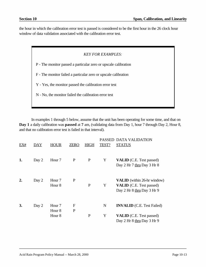
Section 10 Span, Calibration, and Linearity
Acid Rain Program Policy Manual -- March 28, 2000 Page 10-13
KEY FOR EXAMPLES:
P - The monitor passed a particular zero or upscale calibration
F - The monitor failed a particular zero or upscale calibration
Y - Yes, the monitor passed the calibration error test
N - No, the monitor failed the calibration error test
the hour in which the calibration error test is passed is considered to be the first hour in the 26 clock hourwindow of data validation associated with the calibration error test.
In examples 1 through 5 below, assume that the unit has been operating for some time, and that onDay 1 a daily calibration was passed at 7 am, (validating data from Day 1, hour 7 through Day 2, Hour 8,and that no calibration error test is failed in that interval).
PASSED DATA VALIDATIONEX# DAY HOUR ZERO HIGH TEST? STATUS
1. Day 2 Hour 7 P P Y VALID (C.E. Test passed)Day 2 Hr 7 thru Day 3 Hr 8
2. Day 2 Hour 7 P VALID (within 26-hr window)Hour 8 P Y VALID (C.E. Test passed)
Day 2 Hr 8 thru Day 3 Hr 9
3. Day 2 Hour 7 F N INVALID (C.E. Test Failed)Hour 8 PHour 8 P Y VALID (C.E. Test passed)
Day 2 Hr 8 thru Day 3 Hr 9

Span, Calibration, and Linearity Section 10
Page 10-14 Acid Rain Program Policy Manual -- March 28, 2000
PASSED DATA VALIDATION EX# DAY HOUR ZERO HIGH TEST? STATUS
4. Day 2 Hour 7 F N INVALID (C.E. Test Failed)Hour 8 PHour 8 F NHour 8 P N INVALID
(note: injections must be passedconsecutively)
5. Day 2 Hour 7 P VALID (within 26-hr window)Hour 8 P Y VALID (C.E. Test passed)
Day 2 Hr 8 thru Day 3 Hr 9
Day 3 Hour 7 -- -- -- VALID (within 26-hr window)Hour 8 -- -- -- VALIDHour 9 -- -- -- VALIDHour 10 -- -- -- INVALID (26 hr window expired)Hour 11 -- -- -- INVALIDHour 12 P INVALIDHour 13 P Y VALID (C.E. Test passed)
Day 3 Hr 13 thru Day 4 Hr 14
Day 4 Hour 7 F N INVALID (C.E. Test Failed)Hour 8 PHour 8 P Y VALID (C.E. Test passed)
Day 4 Hr 8 thru Day 5 Hr 9
Assume for examples 6 through 10, below that the unit has been off-line for several days, that the laston-line calibration error test was passed 18 hours before the hour of unit shutdown, and that the unit beginsoperation on Day 1 at 1:01 am, during Hour 1. The unit therefore qualifies for a start-up grace period:

Section 10 Span, Calibration, and Linearity
Acid Rain Program Policy Manual -- March 28, 2000 Page 10-15
PASSED DATA VALIDATIONEX# DAY HOUR ZERO HIGH TEST? STATUS
6. Day 1 Hour 1 -- -- -- VALID (start-up grace period)Hour 2 -- -- -- VALIDHour 3 -- -- -- VALIDHour 4 -- -- -- VALID
Hour 5 -- -- -- VALIDHour 6 -- -- -- VALIDHour 7 -- -- -- VALIDHour 8 P Hour 8 P Y VALID (C.E. Test passed)
Day 1 Hr 8 thru Day 2 Hr 9
7. Day 1 Hour 1 -- -- -- VALID (start-up grace period)Hour 2 -- -- -- VALIDHour 3 -- -- -- VALIDHour 4 -- -- -- VALIDHour 5 -- -- -- VALIDHour 6 -- -- -- VALIDHour 7 -- -- -- VALIDHour 8 -- -- -- VALIDHour 9 -- -- -- INVALID (grace period expired)Hour 10 P Hour 10 P Y VALID (C.E. Test passed)
Day 1 Hr 10 thru Day 2 Hr 11
8. Day 1 Hour 1 -- -- – VALID (start-up grace period)Hour 2 -- -- -- VALIDHour 3 -- -- -- VALIDHour 4 -- -- -- VALIDHour 5 PHour 5 F N INVALID (C.E. Test Failed)Hour 6 F NHour 6 P N INVALID (C.E. Test Failed)Hour 7 P Y VALID (C.E. Test passed)
Day 1 Hr 7 thru Day 2 Hr 8

Span, Calibration, and Linearity Section 10
Page 10-16 Acid Rain Program Policy Manual -- March 28, 2000
PASSED DATA VALIDATION EX# DAY HOUR ZERO HIGH TEST? STATUS
9. Day 1 Hour 1 -- -- VALID (start-up grace period)Hour 2 -- -- -- VALID Hour 3 -- -- -- VALID Hour 4 -- -- -- VALID Hour 5 -- -- -- VALID Hour 6 -- -- -- VALID Hour 7 -- -- -- VALID Hour 8 -- -- -- VALID (end of grace period)
Unit shuts down during Day 1 Hour 8, and unit restarts Day 2 Hour 1.
On Day 2, the unit does not meet the criteria to receive an additional 8 hour start up graceperiod because the original grace period ended on Day 1, Hour 8 and no valid on-line calibration errortest was performed within 26 clock hours of the last hour of unit operation on Day 1.
Day 2 Hour 1 -- -- -- INVALID (no grace period)Hour 2 -- -- -- INVALIDHour 3 PHour 3 P Y VALID (C.E. Test passed)
Day 2 Hr 3 thru Day 3 Hr 4
10. Day 1 Hour 1 -- -- -- VALIDa
Hour 2 -- -- -- VALIDHour 3 Unit Trip (Off-Line)b Hour 4 -- -- -- VALIDc
Hour 5 Unit Trip (Off-Line)b Hour 6 -- -- -- VALIDc
Hour 7 -- -- -- VALID Hour 8 -- -- -- VALID Hour 9 -- -- -- INVALIDd
Hour 10 P F N INVALID (C.E. Test Failed)Hour 11 P P Y VALID (C.E. Test passed)
Day 1 Hr 11 thru Day 2 Hr 12
Unit shuts down during Day 1 Hour 11 and restarts Day 2 Hour 3.

Section 10 Span, Calibration, and Linearity
Acid Rain Program Policy Manual -- March 28, 2000 Page 10-17
PASSED DATA VALIDATION EX# DAY HOUR ZERO HIGH TEST? STATUS
10. (cont.)
Day 2 Hour 3 -- -- -- VALIDa
Hour 4 -- -- -- VALIDHour 5 -- -- -- VALIDHour 6 -- -- -- VALIDHour 7 -- -- -- VALIDHour 8 -- -- -- VALIDHour 9 -- -- -- VALIDHour 10 -- -- -- VALIDHour 11 -- -- -- VALIDd
Hour 12 -- -- -- VALIDHour 13 -- -- -- INVALIDe
Hour 14 P P Y VALID (C.E. Test passed) Day 2 Hr 14 thruDay 3 Hr 15
aQualifying start-up grace period begins
bUnit operating time in RT 300 = "0"
cNew start-up "event" begins (Unit operating time in RT 300 = positive). No new grace period(event begins within grace period of a previous event).
dStart-up grace period expired. However, on Day 2, the data are valid because the 26 clock hourwindow from the C.E. test on Day 1, Hour 11 has not expired.
eTwenty-six hour calibration window for the C.E. test on Day 1, Hour 11 has expired.
References: Appendix B, Sections 2.1 through 2.1.5
Key Words: Calibration error, Reporting
History: First published in March 1995, Update #5; revised in October 1999 Revised Manual
Question 10.14 RETIRED
Span, Calibration, and Linearity Section 10
Page 10-18 Acid Rain Program Policy Manual -- March 28, 2000
Question 10.15 REVISED
Topic: Use of Instrument Air for Calibration
Question: May a utility use scrubbed instrument air, with an assumed O2 concentration of 20.9% O2,for calibration of an O2 monitor?
Answer: Yes. However, the O2 monitor span must be set greater than or equal to 21.0% O2. Furthermore, the utility must document that the conditioned gas will not containconcentrations of other gases that interfere with instrument O2 readings (a certificationstatement from the vendor of the gas scrubbing system or equipment will suffice). Also, inthe QA/QC plan for the plant required by Appendix B, include routine maintenance andquality control procedures for ensuring that the instrument air continues to be properlycleaned.
References: § 72.2; Appendix A, Sections 2.1.3 and 5.2.4; Appendix B, Section 1
Key Words: Calibration gases, Diluent monitors, Span
History: First published in July 1995, Update #6; revised in October 1999 Revised Manual
Question 10.16 REVISED
Topic: Monitor Ranges for Units with Low NOx Burners
Question: Are low NOx burners installed at coal fired power plants considered to be add-on emissioncontrol devices? Would utilities with low NOx burners in use be allowed to remove thehigh range of 0 - 1,000 ppm?
Answer: Low NOx burners (LNB) are not considered add-on emission controls. However, asnoted in Section 2.1.2.5(a) of Appendix A, installation of a low-NOx burner is an exampleof a change that may require a span and range adjustment. To determine whether a newspan and range are needed following the installation of a LNB, the owner or operatorshould examine the subsequent NOx emission data in light of the guideline in Section 2.1 ofAppendix A. Specifically, Section 2.1 states: "select the range such that the readingsobtained during typical unit operation are kept, to the extent practicable, between 20.0 and80.0 percent of the full scale range of the instrument." If the NOx concentration readings donot consistently meet this guideline, then the span and range should be adjusted accordingly. If a span adjustment is necessary, base the maximum potential concentration (MPC) usedto determine the new span value on the historical CEMS data (720 hours minimum)
Section 10 Span, Calibration, and Linearity
Acid Rain Program Policy Manual -- March 28, 2000 Page 10-19
collected since the installation of the LNB. If the span and range are changed, provide amonitoring plan update according to Section 2.1.2.5 of Appendix A. For daily calibrationand linearity tests, calibration gases must be used that are consistent with the new spanvalue.
References: Appendix A, Sections 2.1, 2.1.2.4, and 2.1.2.5
Key Words: Control devices, Dual-range monitors, Low NOx burners
History: First published in July 1995, Update #6; revised in October 1999 Revised Manual
Question 10.17 REVISED
Topic: Appendix D and E Orifice Fuel Flowmeter Calibration
Question: A utility has an orifice fuel flowmeter system with three transmitters: a differential pressuretransmitter; an absolute pressure transmitter; and a temperature transmitter. The absolutepressure and temperature transmitters are used to compensate for actual conditions. Thesignals from all three transmitters are combined to determine standard cubic feet per minuteflow rate in order to determine the accuracy of the system.
Appendix D, Section 2.1.5 requires each fuel flowmeter to meet a flowmeter accuracy of ±2.0% of the upper range value (URV). The utility finds it is very difficult to calibrate allthree transmitters at the same time. The temperature can be as high as 300EF, the absolutepressure is 0 - 350 psig and the differential pressure is usually 0 - 100 inches of water(@3.5 psig).
So, how should the utility calibrate and calculate the accuracy of this fuel flowmeter system?
Answer: Check the calibration for the three transmitters separately. Calibrate each transmitter at thezero level and at least two other levels (e.g., mid and high), so that the full range oftransmitter or transducer readings corresponding to normal unit operation is represented. The flowmeter accuracy specification of 2.0% of the URV must be met at each level tested.
If, at a particular level, the accuracy for each transmitter is less than or equal to 1.0% whencalculated according to Equation D-1a in Appendix D, then the fuel flowmeter accuracyspecification of 2.0% of the URV is considered to be met at that level. At each leveltested, report the highest calculated accuracy for any of the transmitters in RT 628 andkeep the results of the tests on the other transmitters on site.

Span, Calibration, and Linearity Section 10
Page 10-20 Acid Rain Program Policy Manual -- March 28, 2000
If, at a particular level, the accuracy of one or more of the transmitters is greater than 1.0%,there are two alternative ways to demonstrate compliance with the fuel flowmeter accuracyspecification of 2.0% of the URV: (1) If the sum of the calculated accuracies for the threetransmitters is less than or equal to 4.0%, the results are considered acceptable; or (2) Ifthe total fuel flowmeter accuracy is # 2.0% when calculated according to Part 1 ofAmerican Gas Association Report No. 3, "General Equations and Uncertainty Guidelines,"the results are considered acceptable.
If the required fuel flowmeter accuracy specification of 2.0% of the URV is not met at anyof the levels tested, follow the applicable procedures in Section 2.1.6.3 of Appendix D("Failure of Transducer(s) or Transmitter(s)").
References: Appendix D, Sections 2.1.5 and 2.1.6
Key Words: Calibration error, Excepted methods, Fuel sampling
History: First published in November 1995, Update #7; revised in October 1999 Revised Manual
Question 10.18 REVISED
Topic: Interference Checks and Data Validation
Question: Does the data validation policy for daily calibration error tests found in Policy ManualQuestion 10.13 also apply to daily interference checks for flow monitors?
Answer: Yes. On November 20, 1996, EPA published revisions to Part 75, which provide astartup grace period for both daily calibration error tests and for daily flow monitorinterference checks. These provisions are found in Section 2.1.5.2 of Appendix B.
References: Appendix A, Section 2.2.2.2; Appendix B, Section 2.1.5.2; Question 10.13
Key Words: Flow monitoring, Quality assurance, Reporting
History: First published in November 1995, Update #7; revised in October 1999 Revised Manual

Section 10 Span, Calibration, and Linearity
Acid Rain Program Policy Manual -- March 28, 2000 Page 10-21
Question 10.19 REVISED
Topic: Maximum Potential Concentration
Question: Can the SO2 and NOx maximum concentrations be adjusted by tracking the hourly valueson a 30 day basis? If so, how should these constants be represented in RT 530 of theelectronic monitoring plan? Also, a stagnant value will cause the ETS-PC to have amismatch when reading the substitution of a dynamically updated value.
Answer: No, do not adjust the maximum potential concentrations each month based upon theconcentrations during the last month. The maximum potential concentration (MPC) isconsidered to be a long term value that will change only if there are significant changes tothe fuel being burned or to the manner of unit operation, or if a required annual evaluation ofthe span and range values or an audit by the regulatory agency shows that an improperspan value (and hence an improper MPC value) has been selected.
References: Appendix A, Sections 2.1.1.5, 2.1.2.5, 2.1.3.2, and 2.1.4.3
Key Words: Monitoring plan, NOx monitoring, SO2 monitoring, Span
History: First published in November 1995, Update #7; revised in October 1999 Revised Manual
Question 10.20 RETIRED
Question 10.21
Topic: Linearity Check for Dual Range Analyzer
Question: Our unit has a dual range analyzer but we generally use only the low range. Must we do alinearity test on the high range each quarter?
Answer: No. A linearity check is only required on the range used during the quarter. Note howeverthat there is an upper limit of four calendar quarters between linearities at each range, soeven if one range were not used at all, a linearity check must be conducted on that range atleast once every four quarters (see Appendix B, Section 2.2.3(f). Also note that for SO2
and NOx, the new rule provides an option for using a default high range value, in lieu ofoperating, maintaining and calibrating a high monitor range (see Appendix A, Sections2.1.1.4(f) and 2.1.2.4(e)).
Span, Calibration, and Linearity Section 10
Page 10-22 Acid Rain Program Policy Manual -- March 28, 2000
References: Appendix A, Sections 2.1.1.4(f) and 2.1.2.4(e); Appendix B, Section 2.2.3(f)
Key Words: Dual range monitors, Linearity
History: First published in October 1999 Revised Manual
Question 10.22
Topic: Off-line Calibration Demonstration Test
Question: Is the off-line calibration demonstration a one time test?
Answer: Yes, unless you are told to repeat the test as the result of an audit or other finding. (SeeEDR instructions for RT 623.)
References: Appendix B, Section 2.1.1.2
Key Words: Calibration
History: First published in October 1999 Revised Manual
Question 10.23
Topic: Separation Between Linearity Checks
Question: The revised rule removes the previous requirement that RATAs be separated by fourmonths. Is there an equivalent change for linearities (which previously had to be separatedby two months)?
Answer: The revised rule now states that successive linearity checks should be separated by 30 daysto the extent practicable.
References: Appendix B, Section 2.2.1
Key Words: Linearity
History: First published in October 1999 Revised Manual

Section 10 Span, Calibration, and Linearity
Acid Rain Program Policy Manual -- March 28, 2000 Page 10-23
Question 10.24
Topic: Grace Period Linearity Check
Question: If we utilize the grace period to perform a linearity check within the first 168 operatinghours of the next quarter, does that grace period linearity count for both quarters?
Answer: No. Each QA operating quarter has a separate linearity requirement.
References: Appendix B, Section 2.2.4
Key Words: Deadlines, Linearity
History: First published in October 1999 Revised Manual
Question 10.25
Topic: Aborted Calibration Test
Question: We aborted the calibration error test of our gas monitor, since the zero level failed. Howshould such aborted calibrations be reported?
Answer: Report the zero level results only. Do not attempt to report any default values (e.g., "999"or "XXX") to simulate a high level injection when the test is aborted after the zero levelcalibration. A single failed gas injection is considered to be a failed calibration error testand puts the monitor in an out-of-control status.
References: § 75.59(a)(1); Appendix B, Section 2.1.6
Key Words: Calibration error, Reporting
History: First published in October 1999 Revised Manual
Span, Calibration, and Linearity Section 10
Page 10-24 Acid Rain Program Policy Manual -- March 28, 2000
Question 10.26
Topic: Flow-to-load Test Failure -- Data Invalidation Period
Question: If we fail a quarterly stack flow-to-load ratio test, what data are invalidated?
Answer: The system is considered out-of-control beginning with the first hour of operation in thequarter following the quarter for which the quarterly stack flow-to-load ratio test failed
References: Appendix B, Section 2.2.5(c)(8)
Key Words: Data validity, Flow-to-load test
History: First published in October 1999 Revised Manual
Question 10.27
Topic: Definition of Over-scaling
Question: Please clarify the definition of over-scaling. Is an instantaneous reading or a one minuteaverage or a 15 minute average above the range considered a full-scale exceedance?
Answer: Over-scaling is an exceedance of the high range of a continuous monitor, as described inAppendix A, Sections 2.1.1.5 (for SO2), 2.1.2.5 (for NOx), and 2.1.4.3 (for flow). Duringhours in which the NOx concentration, SO2 concentration, or flow rate is greater than theanalyzer’s capability to measure, the owner or operator is instructed to substitute 200% ofthe full scale range of the instrument for that hour. This is sufficiently clear for hours inwhich all data recorded by a monitor are off-scale. However, the rule does not givespecific instructions on how to calculate emissions during an hour in which over-scalingoccurs during only part of an hour.
There are two acceptable methods for reporting hourly data when a high scale rangeexceedance occurs only for part of an hour. Regardless of what method is used, themethod must be implemented by the data acquisition and handling system in an automatedfashion so that a value of 200% of the range is automatically substituted at the appropriatetime. The two methods are outlined below:
Section 10 Span, Calibration, and Linearity
Acid Rain Program Policy Manual -- March 28, 2000 Page 10-25
Method 1
(1) Establish the shortest or fundamental averaging period for which data are continuouslyrecorded by the monitor (i.e., the time "x" required for one complete cycle of analyzing,reading, and data recording, where "x" may be 5 seconds, 10 seconds, or 60 seconds,depending on the type of data collection used in the DAHS/CEMS).
(2) If any of the fundamental readings recorded during an hour exceeds the range of theanalyzer (i.e., if over-scaling occurs) then report 200% of the range for that hour andreport an MODC of 20 to indicate a full scale range exceedance.
Method 2
(1) Establish the shortest or fundamental averaging period for which data are continuouslyrecorded by the monitor (i.e., the time "x" required for one complete cycle of analyzing,reading, and data recording, where "x" may be 5 seconds, 10 seconds, or 60 seconds,depending on the type of data collection used in the DAHS/CEMS).
(2) Calculate the hourly average pollutant concentration as the arithmetic average of allfundamental data values recorded during the hour, in the following manner:
(a) If the fundamental reading is lower than the analyzer range, use the reading directlyin the calculation of the hourly average;
(b) If the fundamental reading indicates a range exceedance, then substitute 200% ofthe range for that reading.
(3) Report the hourly average calculated in the manner described in step (2) above as anunadjusted concentration value and use MODC 20 to indicate that a range exceedanceoccurred for at least part of the hour.
References: Appendix A, Sections 2.1.1.5, 2.1.2.5, and 2.1.4.3
Key Words: Monitoring range, Reporting
History: First published in October 1999 Revised Manual
Span, Calibration, and Linearity Section 10
Page 10-26 Acid Rain Program Policy Manual -- March 28, 2000
Question 10.28
Topic: Dual Range Analyzers
Question: For a dual range analyzer defined as two separate components of a single monitoringsystem, which component ID do we report for an hour in which readings from both rangesare used to record data? How is the hourly average concentration determined?
Answer: For the case described (a dual range analyzer defined as two separate components of thesame monitoring system), you may either implement Option 1 or Option 2 below, tocalculate the average concentration and to determine which component ID (low scale orhigh scale) must be reported for an hour in which both ranges are used.
Option 1
(1) Establish the shortest or fundamental averaging period for which data are continuouslyrecorded by the monitor (i.e., the time "x" required for one complete cycle of analyzing,reading, and data recording, where "x" may be 5 seconds, 10 seconds, or 60 seconds,depending on the type of data collection used in the DAHS/CEMS).
(2) If, during a particular hour, one or more fundamental readings are recorded on the highrange, calculate the hourly average as follows:
(a) For all of the quality-assured fundamental readings recorded on the low scaleduring the hour, use the readings directly in the calculation of the hourly average;
(b) For the fundamental reading(s) recorded on the high range during the hour:
(i) If the high range is able to provide quality-assured data at the time of thereading (i.e., if the range is up-to-date with respect to its linearity checkrequirements and has passed a calibration error test within the last 26 clockhours), use the fundamental reading directly in the calculation of the hourlyaverage; or
(ii) If the high range is not quality assured at the time of the reading, substitute themaximum potential concentration (MPC) for the reading and use the substitutevalue in the calculation of the hourly average (see Appendix A, Sections2.1.1.5(b)(2) and 2.1.2.5(b)(2)).
(3) Report data for the hour using the high range component ID.

Section 10 Span, Calibration, and Linearity
Acid Rain Program Policy Manual -- March 28, 2000 Page 10-27
Option 2
(1) Establish the shortest or fundamental averaging period for which data are continuouslyrecorded by the monitor as described in paragraph (1) under Option 1, above.
(2) Calculate the hourly average pollutant concentration as described in paragraphs (2)(a)and (2)(b) under Option 1, above.
(3) Except as noted in paragraph (5) below, if the calculated hourly average from step (2)is less than or equal to the full-scale setting of the low range, use the low rangecomponent ID to report data for the hour.
(4) Except as noted in paragraph (5) below, if the hourly average from step (2) is greaterthan the full-scale setting of the low range, use the high range component ID to reportdata for the hour.
(5) For some dual range CEM systems, an alarm or other mechanism causes the monitor toswitch from the low range to the high range when emissions reach a pre-set level (e.g.,for a low range of 200 ppm, the alarm may cause the high range to be activated whenthe emission level exceeds 175 ppm). For this type of system, use the low rangecomponent ID to report data for the hour if the hourly average from step (2) is less thanor equal to the pre-set emission level at which the high range is activated. Use the highrange component ID to report data for the hour if the calculated hourly averageexceeds the pre-set emission level.
References: Appendix A, Sections 2.1.1.4, 2.1.1.5 , 2.1.2.4, 2.1.2.5
Key Words: Dual range, Reporting
History: First published in March 2000, Update #12
Question 10.29
Topic: Default High Range Value
Question: For units with dual span requirements, in lieu of operating and maintaining a high monitorrange, Sections 2.1.1.4(f) and 2.1.2.4(e) of Appendix A to Part 75 allow the use of adefault high range value of 200% of the MPC when the full-scale of the low range analyzeris exceeded. When the default high range option is selected, how is the hourly average SO2
or NOx concentration calculated? What happens when the full-scale of the low rangeanalyzer is exceeded for only part of the hour?

Span, Calibration, and Linearity Section 10
Page 10-28 Acid Rain Program Policy Manual -- March 28, 2000
Answer: To implement the default high range provision, you may use either of the following options:
Option 1
(1) Establish the shortest or fundamental averaging period for which data are continuouslyrecorded by the monitor (i.e., the time "x" required for one complete cycle of analyzing,reading, and data recording, where "x" may be 5 seconds, 10 seconds, or 60 seconds,depending on the type of data collection used in the DAHS/CEMS).
(2) If any of the fundamental readings recorded during an hour exceeds the full-scale of thelow range analyzer, report 200% of the MPC for that hour and report a method ofdetermination code (MODC) of "19" to indicate the use of the default high range value.
Option 2
(1) Establish the shortest or fundamental averaging period for which data are continuouslyrecorded by the monitor, as described in paragraph (1) of Option 1, above.
(2) Calculate the hourly average pollutant concentration as the arithmetic average of allquality-assured fundamental data values recorded during the hour, in the followingmanner:
(a) If a fundamental reading is less than the full-scale of the low range analyzer, use thereading directly in the calculation of the hourly average;
(b) If a fundamental reading indicates that the low range is "pegged" (i.e., the monitoroutput voltage indicates that the full-scale of the low range has been reached orexceeded), substitute 200% of the MPC for that reading and use the substitutedvalue in the calculation of the hourly average.
(3) Report the hourly average calculated in the manner described in step (2) above as theunadjusted pollutant concentration and report an MODC of "19" to indicate that thedefault high range value was used for at least part of the hour.
References: § 75.57, Table 4A; Appendix A, Sections 2.1.1.4(f), 2.1.2.4(e); EDR v2.1 ReportingInstructions, Sections III.B.(1) and III.B.(2)
Key Words: Default high range, Dual range, Reporting
History: First published in March 2000, Update #12

Section 10 Span, Calibration, and Linearity
Acid Rain Program Policy Manual -- March 28, 2000 Page 10-29
Question 10.30
Topic: Calibration Error Test Following Non-routine Calibration Adjustments
Question: Section 2.1.3 of Appendix B to Part 75 requires an "additional" calibration error test to beperformed whenever "non-routine" calibration adjustments are made to a monitor. Section2.2.3 of Appendix B allows non-routine adjustments prior to quarterly linearity checks. Isit necessary to perform the additional calibration error test prior to the linearity test or canthis calibration error test be performed immediately after the linearity check?
Answer: You may perform the additional calibration error test after the linearity check rather thanprior to the check. However, you must follow the data validation rules in Sections 2.1.3(a)and (c) of Appendix B associated with this calibration error test. Sections 2.1.3(a) and (c)state that following non-routine adjustments, emission data from a monitor are consideredto be invalid until an additional "hands-off"calibration error test has been completed andpassed, which demonstrates that the monitor is operating within its performancespecifications. Therefore, if you perform the additional calibration error test after a linearitycheck, you must invalidate any emission data collected in the time period beginning with thenon-routine adjustment of the monitor and ending at the time of successful completion of thecalibration error test. In order to validate the linearity test, the calibration error test mustshow the monitor to be operating within its performance specification band (± 2.5% ofspan). If the calibration error test shows that the monitor is not operating within itsperformance specification, the linearity test is invalidated and must be repeated. Report an"A" flag in column 69 of each of the RTs 601 in the invalidated linearity test. Do not reportRT 602 for this test.
References: Appendix B, Sections 2.1.3 and 2.2.3
Key Words: Calibration error
History: First published in March 2000, Update #12
Question 10.31
Topic: Linearity Check Following Span Adjustment
Question: If a facility changes the span of a gas monitor, is a linearity check required?
Answer: It depends. Sections 2.1.1.5 and 2.1.2.5 of Appendix A to Part 75 require a diagnosticlinearity check to be performed following a span adjustment of a gas monitor only if the

Span, Calibration, and Linearity Section 10
Page 10-30 Acid Rain Program Policy Manual -- March 28, 2000
span adjustment is so significant that the calibration gases currently used for daily calibrationerror tests and linearity checks are unsuitable for use with the new span value. Forinstance, suppose that the span of a NOx monitor is 1000 ppm and the "low," "mid," and"high" calibration gases currently in use have concentrations of 250 ppm, 525 ppm, and 825ppm, respectively. If, following a required annual span and range evaluation, the span ischanged to 900 ppm, these calibration gas concentrations, expressed as percentages of thenew span value, would be, respectively, 27.8%, 58.3%, and 91.6%. Since the calibrationgases are still within the tolerance bands for low, mid, and high-level concentrations (i.e.,20.0-30.0% of span for low-level, 50.0-60.0% of span for mid-level, and 80.0-100.0% ofspan for high level), a diagnostic linearity check would not be required in this case. However, if the span had been lowered to 800 ppm or less, the current calibration gaseswould no longer be within the tolerance bands and a diagnostic linearity check would berequired.
In cases where a span adjustment is required and the current calibration gases areunsuitable for use with the new span value, the owner or operator has up to 90 days afterthe end of the quarter in which the need to adjust the span is identified to implement thechange (see Sections 2.1.1.5 and 2.1.2.5 of Appendix A). This allows time to purchaseand receive the new calibration gases.
References: Appendix A, Section 2.1.1.5 and 2.1.2.5
Key Words: Linearity, Span
History: First published in March 2000, Update #12
Question 10.32
Topic: Diagnostic Linearity Check
Question: If, during a "QA operating quarter," a successful diagnostic linearity check is performedfollowing a change to the span of a gas monitor, may this diagnostic linearity check be usedto meet the quarterly linearity check requirement of Section 2.2.1 of Appendix B to Part75?
Answer: Yes. This is consistent with Section 2.4 of Appendix B, which allows quality assurancetests to serve a dual purpose. In the example cited in Section 2.4, a single linearity check isused to meet a recertification requirement and to satisfy the routine quality assurancerequirements of Appendix B.
Section 10 Span, Calibration, and Linearity
Acid Rain Program Policy Manual -- March 28, 2000 Page 10-31
In EDR v2.1, there is a new field in column 75 of RT 601 (Linearity Check Results), inwhich the "Reason for Test" is reported (e.g., "Q" = routine quality assurance, "D" =diagnostic, "R" = recertification, etc.). When a test is performed for a dual purpose, a two-letter code is used. In the present example, since the linearity check is done both forroutine quality assurance and as a diagnostic test, the code "QD" would be reported in RT601, column 75.
References: Appendix B, Sections 2.2.1 and 2.4; EDR v2.1, RT 601
Key Words: Linearity check, Reporting
History: First published in March 2000, Update #12
Question 10.33
Topic: Span and Range -- Annual Evaluation
Question: What must I do to comply with the provisions of Sections 2.1.1.5, 2.1.2.5, and 2.1.4.3 ofAppendix A to Part 75, which require an annual evaluation of the span and range of mycontinuous emission monitors? Are there any other times at which span and rangeevaluations would be required?
Answer: To comply with the annual span and range evaluation provisions of Part 75, you mustexamine your historical CEMS data at least once per year to see if the current span andrange values meet the guideline in Section 2.1 in Appendix A. According to that guideline,the full-scale range of a monitor must be selected so that data recorded during normaloperation are kept, to the extent practicable, between 20.0 and 80.0% of full-scale. Section 2.1 also describes several allowable exceptions to the "20-to-80 percent of range"criterion.
The annual span and range evaluation may be done in any quarter of the year. At aminimum, the evaluation consists of examining all measured CEMS data (not substitutedata) from the previous four calendar quarters, for each pollutant or parameter (i.e., SO2
concentration, NOx concentration, CO2 concentration, and flow rate). You may alsoinclude data recorded in the quarter of the evaluation. For example, if the data analysis isperformed in the fourth quarter of the year, the analysis must include all data from the 4thquarter of previous year through the 3rd quarter of the current year, and may (at thediscretion of the owner or operator) include additional data from the 4th quarter of thecurrent year.

Span, Calibration, and Linearity Section 10
Page 10-32 Acid Rain Program Policy Manual -- March 28, 2000
Determine the percentage of the data that fall between 20.0 and 80.0% of full-scale and thepercentage of the data that fall outside this range. The introductory text to Sections 2.1.1.5,2.1.2.5, and 2.1.4.3 of Appendix A makes it clear that data recorded during short-term,non-representative operating conditions (such as a trial burn of a different fuel) should beexcluded from the data analysis. If the majority (>50%) of the historical data are found tobe within the 20.0 to 80.0% band, the current span and range values are acceptable andmay continue to be used.
The results of annual span and range evaluations must be kept on-site, in a format suitablefor inspection (see introductory text to Sections 2.1.1.5, 2.1.2.5, and 2.1.4.3 of AppendixA). Do not send these results to EPA.
If, for any pollutant or parameter, the results of the annual span and range evaluation fail tomeet the guideline in Section 2.1 of Appendix A, Sections 2.1.1.5(a), 2.1.2.5(a), and2.1.4.3(a) of Appendix A require that you adjust the span and range. When span andrange adjustments are required, you have up to 45 days after the end of the quarter inwhich the need to adjust the span is identified (in this case, the quarter of the span andrange evaluation) to implement the change, with one exception—for span and rangechanges to a gas monitor that require new calibration gases to be purchased because thecurrent calibration gases are unsuitable for use with the new span value, you have up to 90days after the end of the quarter of the unsatisfactory span and range evaluation toimplement the span and range changes.
In addition to the annual evaluations, you may also have to conduct span and rangeevaluations whenever you plan to change the manner of operation of the affected unit(s),such that the emissions or flow rates may change significantly (see Sections 2.1.1.5(a),2.1.2.5(a), and 2.1.4.3 of Appendix A). For example, installation of emission controls mayrequire certain monitors to be re-spanned and re-ranged. You should plan any span andrange changes needed to account for such changes in unit operation, so that they are madein as timely a manner as practicable to coordinate with the operational changes.
References: Appendix A, Sections 2.1.1.5(a), 2.1.2.5(a), and 2.1.4.3(a)
Key Words: Span
History: First published in March 2000, Update #12
Section 10 Span, Calibration, and Linearity
Acid Rain Program Policy Manual -- March 28, 2000 Page 10-33
Question 10.34
Topic: Preapproval for Use of Mid-level Calibration Gas
Question: If we use the new provision allowing the use of mid-level calibration gas, do we have to getpreapproval?
Answer: No, preapproval is not required.
References: Appendix A, Section 6.3.1
Key Words: Calibration gases
History: First published in March 2000, Update #12
Question 10.35
Topic: Justification for Non-routine Calibration Adjustment
Question: What is an acceptable technical justification for a non-routine calibration adjustment? Therule states that such adjustments may be made prior to a RATA or linearity. May they alsobe made after any daily calibration?
Answer: Non-routine adjustments are allowed prior to RATAs and linearities because calibrationgases are only guaranteed accurate to within 2% of the tag value. For daily calibrations,users of dilution-extractive systems that are very sensitive to ambient conditions, the revisedrule allows an adjustment away from the tag value (but still within the performancespecification band), when it is justified on technical grounds, such as an anticipatedbarometric pressure change, and is part of the QA plan for the CEMS. An additionalcalibration error test must be performed after non-routine adjustments to demonstrate thatthe analyzer is still operating within its performance specifications.
References: Appendix B, Section 2.1.3(c)
Key Words: Calibration error, Linearity, RATA
History: First published in March 2000, Update #12
Span, Calibration, and Linearity Section 10
Page 10-34 Acid Rain Program Policy Manual -- March 28, 2000
Question 10.36
Topic: MPC for Units With Low NOx Levels
Question: There will be many new units coming online in the Northeast with NOX emissions controlledto very low levels. How can we determine MPC for those units? If we use the constantsprovided in Tables 2-1 or 2-2 of Appendix A to Part 75, we will have to revise the MPC,span, and range values once historical data has been obtained.
Answer: If you believe that the values in Tables 2-1 and 2-2 are unrepresentative of the maximumpotential NOx concentration for your affected unit, you may petition EPA under § 75.66 forpermission to use an alternative MPC value (e.g., a reliable estimate of the uncontrolledemissions provided by the turbine manufacturer).
References: § 75.66
Key Words: NOx monitoring
History: First published in March 2000, Update #12
Question 10.37
Topic: Effects of BAF on Full-scale Exceedance Reporting
Question: When full-scale exceedances of a high-scale monitoring range occur, Part 75 requires avalue of 200% of the range to be reported. If the full-scale range is exceeded for only partof the hour, Policy Question 10.27 allows the hourly average to be calculated using acombination of real monitored data and the default value of 200% of the range. Whathappens if an hourly average SO2 concentration calculated in this manner is multiplied bythe bias adjustment factor (BAF), and gives a result greater than 200% of the range (e.g., ifdata are off -scale for 59 minutes of the hour and on-scale for one minute)? Will theEmission Tracking System (ETS) give an error message?
Answer: If the calculated hourly average SO2 concentration times the BAF gives a result less than orequal to 200% of the range, report this result as the bias-adjusted SO2 concentration. Ifthe calculated SO2 concentration times the BAF gives a result higher than 200% of therange, report 200% of the range as the bias-adjusted concentration. This will ensure thatno error message is generated by ETS.
Section 10 Span, Calibration, and Linearity
Acid Rain Program Policy Manual -- March 28, 2000 Page 10-35
Note that when a "default high range" SO2 value of 200% of the MPC is used forexceedances of a low-scale monitor range (as allowed under Section 2.1.1.4 (f) ofAppendix A to Part 75), similar considerations apply. If the calculated hourly average SO2
concentration times the BAF gives a result less than or equal to 200% of the MPC, reportthis result as the bias-adjusted SO2 concentration. If the calculated SO2 concentrationtimes the BAF gives a result higher than 200% of the MPC, report 200% of the MPC asthe bias-adjusted concentration (see Policy Question 10.29).
References: Appendix A, Sections 2.1.1.4(f), 2.1.1.5(b)
Key Words: Bias adjustment factor, Range
History: First published in March 2000, Update #12

Span, Calibration, and Linearity Section 10
Page 10-36 Acid Rain Program Policy Manual -- March 28, 2000
[This page intentionally left blank.]
Acid Rain Program Policy Manual -- March 28, 2000 Page 11-i
SECTION 11OTHER QA/QC REQUIREMENTS
Page
11.1 QA/QC Plan . . . . . . . . . . . . . . . . . . . . . . . . . . . . . . . . . . . . . . . . . . . . . . . . . 11-1
11.2 QA/QC Plan . . . . . . . . . . . . . . . . . . . . . . . . . . . . . . . . . . . . . . . . . . . . . . . . . 11-1
11.3 REVISED Flow Temperature QA . . . . . . . . . . . . . . . . . . . . . . . . . . . . . . . . 11-2
11.4 Hands-off Requirement for QA Testing . . . . . . . . . . . . . . . . . . . . . . . . . . . . . . 11-2
11.5 Appendix A, Section 2.2 Deletion . . . . . . . . . . . . . . . . . . . . . . . . . . . . . . . . . . 11-3
11.6 QA Plan Format . . . . . . . . . . . . . . . . . . . . . . . . . . . . . . . . . . . . . . . . . . . . . . . 11-3

Other QA/QC Requirements Section 11
Page 11-ii Acid Rain Program Policy Manual -- March 28, 2000
[This page intentionally left blank]
Section 11 Other QA/QC Requirements
Acid Rain Program Policy Manual -- March 28, 2000 Page 11-1
Question 11.1
Topic: QA/QC Plan
Question: What are the specific requirements for content of a QA/QC Plan?
Answer: The minimum requirements for a Quality Assurance/Quality Control (QA/QC) Plan arespecified in Appendix B to 40 CFR Part 75.
References: Appendix B, Section 1
Key Words: Quality assurance, Recordkeeping
History: First published in Original March 1993 Policy Manual
Question 11.2
Topic: QA/QC Plan
Question: Must the QA/QC Plan be submitted to EPA?
Answer: The final Part 75 rule does not require that the QA/QC Plan be submitted to EPA. Rather, as specified in the "Response to Public Comment" document, the intent of therule is that the Plan be maintained at the applicable plant site and that the Plan beupdated as necessary. Since the requirement to conduct daily assessments on thesystem is effective as of the date when certification testing is completed (see Section2.1 of Appendix B to 40 CFR Part 75), the Plan should be in place as of the datecertification testing is conducted on a CEM system.
References: § 75.54(a)(4), § 75.57(a)(4)
Key Words: Quality assurance, Recordkeeping
History: First published in Original March 1993 Policy Manual
Other QA/QC Requirements Section 11
Page 11-2 Acid Rain Program Policy Manual -- March 28, 2000
Question 11.3 REVISED
Topic: Flow Temperature QA
Question: How should we quality assure temperature monitoring devices used by a flow monitorto determine temperature corrections?
Answer: Since there are no separate performance specifications for temperature measurementequipment, there are no QA procedures that must be used to evaluate the accuracy oftemperature calculations performed by such monitoring devices. The accuracy ofmeasurements made with such devices, however, will be determined through periodic(semiannual or annual) relative accuracy test audits of the flow monitor and thequarterly flow-to-load ratio evaluations.
References: Appendix A, Sections 3, 6.5, and 7.2; Appendix B, Section 2.2.5
Key Words: Flow monitoring, Flow-to-load test, Quality assurance, RATAs
History: First published in Original March 1993 Policy Manual; revised in October 1999Revised Manual
Question 11.4
Topic: Hands-off Requirement for QA Testing
Question: Please clarify what is meant by performing a QA test hands-off.
Answer: For daily calibration error tests, hands-off means that the zero and upscale calibrationsare performed in succession, with no adjustments to the monitor. For linearity testsand RATAs, the hands-off requirement means that only routine calibration adjustments(as defined in Appendix B, Section 2.1.3) are allowed during the test. For example, ifthe linearity test for a peaking unit extends over more than one day and a routine dailycalibration error test is performed before completing the linearity check, the monitormay be adjusted after the daily calibration error test, but only in a routine manner (i.e.,so as to match (to the extent practicable) the calibration gas tag value). For flowRATAs, hands-off also means that the polynomial coefficients or K factor(s) must notbe changed, either during the test at a particular load level or in-between load levels. The rule requires a three-load flow RATA if the polynomials or K-factor(s) areadjusted.
Section 11 Other QA/QC Requirements
Acid Rain Program Policy Manual -- March 28, 2000 Page 11-3
References: Appendix B, Section 2.1.3
Key Words: Calibration error, Linearity, RATAs
History: First published in October 1999 Revised Manual
Question 11.5
Topic: Appendix A, Section 2.2 Deletion
Question: Section 2.2 of Appendix A appears to have been removed from Part 75, according tothe May 26, 1999 version of the Federal Register. Does that mean that this section isno longer applicable?
Answer: Section 2.2 of Appendix A was removed from the May 26, 1999 version by error andis still applicable. EPA will issue a technical correction that reinstates Section 2.2 ofAppendix A.
References: Appendix A, Section 2.2
Key Words: N/A
History: First published in October 1999 Revised Manual
Question 11.6
Topic: QA Plan Format
Question: Does our QA Plan need to have a standard format? We refer to other documents,such as manuals provided by vendors, but the information in these documents is notincluded in the QA Plan. Do we need to retype/reword the information in the manualand include it in the QA Plan?
Answer: No standard format is required and it is not necessary to retype the information fromthe other manuals. The QA Plan should reference the other documents and thesedocuments should be available on site.
References: Appendix B, Section 1
Other QA/QC Requirements Section 11
Page 11-4 Acid Rain Program Policy Manual -- March 28, 2000
Key Words: Quality assurance
History: First published in March 2000, Update #12
Acid Rain Program Policy Manual -- March 28, 2000 Page 12-i
SECTION 12CERTIFICATION:
ADMINISTRATIVE/PROCEDURAL
Page
12.1 REVISED Monitoring Plan . . . . . . . . . . . . . . . . . . . . . . . . . . . . . . . . . . . . . 12-1
12.2 RETIRED
12.3 Pre-certification Requirements . . . . . . . . . . . . . . . . . . . . . . . . . . . . . . . . . . . . 12-1
12.4 RETIRED
12.5 RETIRED
12.6 RETIRED
12.7 REVISED Certification Applications . . . . . . . . . . . . . . . . . . . . . . . . . . . . . . 12-2
12.8 Timing of Tests . . . . . . . . . . . . . . . . . . . . . . . . . . . . . . . . . . . . . . . . . . . . . . . . 12-3
12.9 Certification Testing . . . . . . . . . . . . . . . . . . . . . . . . . . . . . . . . . . . . . . . . . . . . 12-3
12.10 RETIRED
12.11 REVISED Certification Application -- Paper Documentations . . . . . . . . . . . 12-4
12.12 Certification Test Notification . . . . . . . . . . . . . . . . . . . . . . . . . . . . . . . . . . . . . 12-5
12.13 REVISED Scrubber Installation -- Certification Timeline . . . . . . . . . . . . . . . 12-5
12.14 REVISED Certification of Excepted Methods . . . . . . . . . . . . . . . . . . . . . . . 12-6
12.15 RETIRED
Certification: Administrative/Procedural Section 12
Page 12-ii Acid Rain CEM Program Policy Manual -- March 28, 2000
Page
12.16 RETIRED
12.17 7-day Calibration Error Test . . . . . . . . . . . . . . . . . . . . . . . . . . . . . . . . . . . . . . 12-7
12.18 REVISED Fuel Flowmeter Calibration Methods . . . . . . . . . . . . . . . . . . . . . 12-8
12.19 REVISED Accuracy Specifications for Gas Fuel Flowmeters . . . . . . . . . . . . 12-9
12.20 RETIRED
12.21 RETIRED
12.22 RETIRED
12.23 REVISED Fuel Flowmeter Certification . . . . . . . . . . . . . . . . . . . . . . . . . . . . 12-9
12.24 RETIRED
12.25 RETIRED
12.26 REVISED Alternatives to ASTM/ASME Methods Incorporated by Reference . . . . . . . . . . . . . . . . . . . . . . . . . . . . . . . . . . . . . . 12-10
12.27 REVISED Fuel Flowmeter -- Accuracy Information . . . . . . . . . . . . . . . . . 12-11
12.28 RETIRED
12.29 RETIRED

Section 12 Certification: Administrative/Procedural
Acid Rain Program Policy Manual -- March 28, 2000 Page 12-1
Question 12.1 REVISED
Topic: Monitoring Plan
Question: For an initial monitoring plan, do we use current conditions or conditions that will beapplicable at the time of the certification tests?
Answer: Since the initial monitoring plan is submitted prior to the certification tests, the planshould reflect the expected conditions at the time when the certification tests will beconducted. However, if there should be a change in any of these conditions prior tothe testing, the owner or operator is required under § 75.53(b) to update themonitoring plan accordingly.
References: § 75.53
Key Words: Certification tests, Monitoring plan
History: First published in Original March 1993 Policy Manual; revised in October 1999Revised Manual
Question 12.2 RETIRED
Question 12.3
Topic: Pre-certification Requirements
Question: Is there a required minimum run time for a CEM system before certification?
Answer: With the exception of opacity monitors being certified in accordance with PerformanceSpecification (PS) 1 from Appendix B of 40 CFR Part 60, there is no minimum runtime prior to certification. Opacity monitors being certified in accordance with PS 1are subject to a 168-hour conditioning period that precedes a 168-hour operationaltest period.
References: 40 CFR Part 60, Appendix B (PS 1)

Certification: Administrative/Procedural Section 12
Page 12-2 Acid Rain Program Policy Manual -- March 28, 2000
Key Words: Certification tests, Opacity monitoring
History: First published in Original March 1993 Policy Manual
Question 12.4 RETIRED
Question 12.5 RETIRED
Question 12.6 RETIRED
Question 12.7 REVISED
Topic: Certification Applications
Question: May a utility submit certification applications separately for different CEM systems(e.g., SO2 and NOx) at one unit? If the utility unit submits one certification application,will EPA issue partial approvals?
Answer: Yes. The utility may choose to conduct certification activities separately. The utilitywould have to give proper (45-day) advance notice for each battery of tests, andwould have 45 days after completion of each series of tests to submit the results. The120-day review time would apply individually to each submission. However, the ruledoes require that some monitors at the unit be tested concurrently for certification;specifically, NOx-diluent monitoring systems, and where applicable, SO2-diluentmonitoring systems (through 1999).
EPA may also issue separate certification approvals in some cases where a utilitysubmits one certification application for all the monitoring systems at one unit. Forexample, if EPA determines that all but one of the monitoring systems passed thecertification requirements, then EPA would issue a disapproval only for the monitoringsystem (e.g., the SO2 system) which failed, and would issue a certification approval forthe rest (e.g., the NOx-diluent system, flow monitor, CO2 monitoring system, andopacity monitoring system).
Section 12 Certification: Administrative/Procedural
Acid Rain Program Policy Manual -- March 28, 2000 Page 12-3
References: § 75.20; Appendix A, Section 6.5
Key Words: Certification applications, Deadlines, EPA approvals
History: First published in Original March 1993 Policy Manual; revised in October 1999Revised Manual
Question 12.8
Topic: Timing of Tests
Question: Must the 7-day calibration error test and the linearity test be conducted at the sametime as the RATA?
Answer: No. In fact, EPA recommends that utility sources complete the required certificationtests in the following order: the DAHS verification tests, the cycle/response time test,the linearity check, the 7-day calibration error test, and the RATA tests.
References: Appendix. A, Section 6.1
Key Words: Calibration error, Certification process, Linearity, RATAs
History: First published in Original March 1993 Policy Manual
Question 12.9
Topic: Certification Testing
Question: If a company has personnel on staff with stack testing expertise, is it permissible for thecompany to conduct their own CEMS certification tests, rather than hiring an outsidetesting firm?
Answer: Yes. Section 75.20(c) requires that the owner or operator conduct certification tests;the owner or operator may use either company personnel or hired personnel from anoutside testing firm to conduct these tests.
References: § 75.20(c)

Certification: Administrative/Procedural Section 12
Page 12-4 Acid Rain Program Policy Manual -- March 28, 2000
Key Words: Certification tests
History: First published in May 1993, Update #1
Question 12.10 RETIRED
Question 12.11 REVISED
Topic: Certification Application -- Paper Documentation
Question: It is easy to generate certification test results within a week or so in electronic format,but paper often takes much longer. Is there flexibility in the requirement for submissionof the certification application 45 days after testing (especially for the extra papercopies)?
Answer: No. A complete application is due within 45 days. A unit will be out of compliance ifit does not submit a complete application within 45 days. However, if a utility finds itcannot submit a complete application, then it would be prudent to submit the electronicdata within the 45 day period and the hard copy information shortly thereafter. Notethat EPA's 120 day review period will not begin until all paper documentation isreceived, thus completing the certification application. For recertification applications,the EPA Regional Office (and the applicable State and/or local agency) may waive therequirement to receive the hardcopy portion of the application. For both certificationand recertification applications, the designated representative does not have to submita hardcopy portion of the application to EPA Headquarters.
References: § 75.56, § 75.59, § 75.63
Key Words: Certification applications, Deadlines
History: First published in May 1993, Update #1; revised July 1995, Update #6; revised inOctober 1999 Revised Manual

Section 12 Certification: Administrative/Procedural
Acid Rain Program Policy Manual -- March 28, 2000 Page 12-5
Question 12.12
Topic: Certification Test Notification
Question: From what date do we count back to determine the date of the certification testingnotification? Is it based upon the date of the RATA?
Answer: Forty-five (45) days prior to the first day upon which the first certification test is begun. It is the first test that matters, not one particular test such as the RATA or 7-daycalibration error test.
References: § 75.61(a)
Key Words: Certification process, Notice
History: First published in November 1993, Update #2
Question 12.13 REVISED
Topic: Scrubber Installation -- Certification Timeline
Question: How much time after CEMS installation at the scrubber do we have to certify theoperation of the CEMS?
Answer: In accordance with the provisions of § 75.4(e) in the direct final rule published May17, 1995, all certification testing of the CEMS installed at the scrubber must becomplete within "90 calendar days after the date that the emissions first exit to theatmosphere through the new stack, flue, or flue gas desulfurization system. . ."
References: § 75.4(e)
Key Words: Certification tests, Control devices
History: First published in November 1993, Update #2; revised July 1995, Update #6

Certification: Administrative/Procedural Section 12
Page 12-6 Acid Rain Program Policy Manual -- March 28, 2000
Question 12.14 REVISED
Topic: Certification of Excepted Methods
Question: How does the certification process work for approved exceptions to CEMS (theprocedures in Appendices D and E of 40 CFR Part 75)?
Answer: The designated representative submits a monitoring plan at least 45 days prior tobeginning certification testing (i.e., the date of the first test for either the Appendix D orthe Appendix E method). The initial submission of the monitoring plan should includethe monitoring methods to be used, data supporting the accuracy of fuel flow meters,schematic diagrams showing fuel flowmeter and oil sampling locations, as well asCEMS and COMS locations, and capacity factor and fuel usage data to demonstrateapplicability of the monitoring methods to be used from Appendix D or E.
The designated representative also submits a certification testing notification toEPA and the State or local agency at least 45 days prior to beginning certificationtesting for Appendix E only (no test notification requirements apply for Appendix D,including fuel flowmeter calibration testing). For a unit using the procedures inAppendix E, the certification testing notification includes the testing procedures that willbe used in the NOx emission rate/load correlation (including the planned load levels,fuels, and excess O2 levels).
Provisional certification also applies for Appendix D or E procedures. This wouldapply upon successful completion of all test results included in the certificationapplication, including test results demonstrating the flowmeter accuracy and the resultsof any DAHS verification tests developed for these methods.
The designated representative submits a certification application within 45 days aftercompleting certification testing to EPA and to the appropriate State or local agency. This certification application includes results of any DAHS verification tests and a finalmonitoring plan, including: test data supporting the fuel flowmeter accuracy; testingresults from the correlation of NOx emission rate and load (for Appendix E proceduresonly); and data for deriving the F-factor used (for Appendix E procedures only).
As with certification of a CEMS, EPA has a 120 day period for review of acertification application for an excepted monitoring method. The 120 day period startsupon EPA's receipt of a complete certification application, including the finalmonitoring plan with all test results for the methods in Appendices D and E, and testresults for the DAHS.
References: § 75.20(g), § 75.63, Appendices D and E

Section 12 Certification: Administrative/Procedural
Acid Rain Program Policy Manual -- March 28, 2000 Page 12-7
Key Words: Certification process, Excepted methods
History: First published in November 1993, Update #2; revised in October 1999 RevisedManual
Question 12.15 RETIRED
Question 12.16 RETIRED
Question 12.17
Topic: 7-day Calibration Error Test
Question: Must a unit operate continuously for all 168 hours of the 7-day calibration error testduring certification?
Answer: No, for purposes of Part 75. (Under many other programs, such as the New SourcePerformance Standards, a unit must operate continuously for 168 hours while thecalibration drift test for certification is performed.)
According to Section 6.1 of Appendix A, units must be operating when measurementsare made. The same section of Appendix A of Part 75 specifies that units may betested on non-consecutive calendar days (but the certification test must be performedon seven consecutive unit operating days). This allows certification testing of CEMSon peaking and intermediate load units at actual stack conditions and at conditionssimilar to those that will be encountered later after certification.
When a unit has been shutdown, the monitor readings may drift. In order to improvemonitor accuracy when the unit is again operating and to allow the monitor to pass the7-day calibration error test, it is permissible to check the calibration of the instrumentand adjust it while the unit is still shutdown. Calibration tests during shutdown periodsare not to be reported as part of the 7-day calibration error test data. When a unitcomes back on-line after an outage, it is recommended that the 7-day calibration errortest not be resumed until the unit operation has stabilized. This allows the monitor tomeasure while its probe is exposed to normal flue gas moisture and temperatureconditions.

Certification: Administrative/Procedural Section 12
Page 12-8 Acid Rain Program Policy Manual -- March 28, 2000
References: Appendix A, Section 6.1
Key Words: Calibration error, Certification tests
History: First published in November 1993, Update #2
Question 12.18 REVISED
Topic: Fuel Flowmeter Calibration Methods
Question: Has EPA approved any calibration methods for fuel flowmeters besides the standardslisted in § 75.20(g)(1)(I) (in the direct final rule published May 17, 1995)?
Answer: Yes. In the rule revisions promulgated on May 26, 1999, EPA combined the list ofapproved methods in § 75.20(g)(1)(I) with the existing list in section 2.1.5.1 ofAppendix D to Part 75 to avoid repetition and potential inconsistency. In addition,EPA revised one of the approved methods to refer to the most recent version of themethod: American Gas Association (AGA) Report No. 7, Measurement of Gas byTurbine Meters, section 8 (Second Revision, April, 1996). However, EPA willcontinue to accept results for meters already in place that met the earlier versions ofthis design standard (either the 1981 or 1985 editions). In addition, EPA addedSections 2, 3 and 5 from Chapter 4 of the Manual of Petroleum MeasurementStandards, October 1988 (Reaffirmed 1993) (American Petroleum Institute) to the listof approved procedures to verify accuracy or design.
To obtain permission to use other methods, designated representatives should combinethe information required for a petition under § 75.23 and § 75.66(c) with themonitoring plan and certification application. The Agency will then review the petitionas part of the certification application.
References: § 75.20(g)(1)(I), § 75.23, § 75.66; Appendix D, Section 2.1.5.1, Question 12.26
Key Words: Excepted methods, NOx monitoring, SO2 monitoring
History: First published in October 1994, Update #3; revised July 1995, Update #6; revised inOctober 1999 Revised Manual

Section 12 Certification: Administrative/Procedural
Acid Rain Program Policy Manual -- March 28, 2000 Page 12-9
Question 12.19 REVISED
Topic: Accuracy Specifications for Gas Fuel Flowmeters
Question: What is the flowmeter accuracy specification for a gas flowmeter for use in AppendixD or E of Part 75?
Answer: Section 2.1.5 specifies an accuracy specification of 2.0 percent of the upper rangevalue (URV). Section 2.1.2 of Appendix D requires that each fuel flowmeter used tomeet the requirements of the protocols in Appendix D and Appendix E satisfy thisaccuracy specification, except for certain situations as provided in Section 2.1.4 ofAppendix D.
References: Appendix D, Section 2.1.1
Key Words: Excepted methods, NOx monitoring, SO2 monitoring
History: First published in August 1994, Update #3; revised in October 1999 Revised Manual
Question 12.20 RETIRED
Question 12.21 RETIRED
Question 12.22 RETIRED
Question 12.23 REVISED
Topic: Fuel Flowmeter Certification
Question: For initial certification of fuel flowmeters, how old may calibration data be and still beconsidered valid for certification test purposes?
Answer: Initial certification test results for accuracy of a fuel flowmeter should be no more thana year old. Except for orifice, nozzle, and venturi-type flowmeters, EPA generally

Certification: Administrative/Procedural Section 12
Page 12-10 Acid Rain Program Policy Manual -- March 28, 2000
expects utilities to retest or recalibrate their fuel flowmeters annually (or once everyfour fuel flowmeter QA operating quarters for intermittently operated units). Thisrequirement may be extended to once every five years where a source conducts fuelflow-to-load testing under Section 2.1.7 of Appendix D. These exceptions to annualretesting or recalibration are intended to provide reduced burdens for ongoing qualityassurance requirements for infrequently operated units or where the unit substitutes thefuel flow-to-load test for a direct calibration. The Agency does not believe that eitherof these exceptions are warranted or applicable for initial certification of a fuelflowmeter for use under Part 75.
For orifice, nozzle, and venturi-type meters, the initial calibration includes physicalinstallation of the orifice, which will not change; therefore, it is appropriate to use thatinitial installation and calibration information to apply for initial certification of an orifice,nozzle, or venturi fuel flowmeter, even if it is more than a year old. If the orifice,nozzle, or venturi-type flowmeter is more than a year old, perform a visual inspectionof the meter and a calibration of the pressure and temperature transmitters before usingthe fuel flowmeter to provide data for the Acid Rain Program.
References: § 75.20(g)(1); Appendix D, Sections 2.1.5 through 2.1.7
Key Words: Calibration, Certification tests, Excepted methods
History: First published in July 1995, Update #6; revised in October 1999 Revised Manual
Question 12.24 RETIRED
Question 12.25 RETIRED
Question 12.26 REVISED
Topic: Alternatives to ASTM/ASME Methods Incorporated by Reference
Question: I want to use an alternative method for calibrating my fuel flowmeter that is not listed inSection 2.1.5.1 of Appendix D. What do I need to submit to EPA to get thealternative procedure approved?
Section 12 Certification: Administrative/Procedural
Acid Rain Program Policy Manual -- March 28, 2000 Page 12-11
Answer: Submit the information required under § 75.23 and § 75.66(a) and (c) for analternative to an ASTM method or other standard incorporated by reference. Thisincludes: (1) a description of why the prescribed Part 75 method (or methods) is notbeing used; (2) a description and diagram(s) of any equipment and procedures used inthe proposed alternative; (3) information demonstrating that the proposed alternativeproduces data acceptable for use in the Acid Rain Program, including accuracy andprecision statements, NIST traceability certificates or protocols, or other supportingdata; and (4) the designated representative certification statements required by§ 72.21.
The procedures and description of equipment should be sufficiently detailed that anobserver would be able to tell if the procedures and equipment were being used.
Note that it is the submitter's responsibility to demonstrate that the alternative to thestandard in Part 75 will give equivalent results and is acceptable. If any of the elementsdiscussed above are missing, EPA may request further information or even disapprovethe petition.
References: § 75.23, § 75.66(c); Appendix D, Section 2.1.5.1; Question 12.18
Key Words: ASTM methods, Calibration, Petitions
History: First published in July 1995, Update #6; revised in October 1999 Revised Manual
Question 12.27 REVISED
Topic: Fuel Flowmeters -- Accuracy Information
Question: What information must I submit with my certification or recertification application todemonstrate accuracy of a fuel flowmeter?
Answer: Submit data and calculations to demonstrate that the fuel flowmeter meets an accuracyof 2.0% of the upper range value. When calibration is done using one of the allowablemethods in Section 2.1.5.1 or by comparison against a reference flowmeter, asdescribed in Section 2.1.5.2 of Appendix D, include:
(1) Range of the instrument at which calibration was conducted (usually expressed asa percentage of the upper range value). Data should include the full scale valueand at least two other values.
(2) The upper range value--URV (full scale).
Certification: Administrative/Procedural Section 12
Page 12-12 Acid Rain Program Policy Manual -- March 28, 2000
(3) Readings from the flowmeter being tested (in lbs/min, scfh, or other appropriateunits).
(4) Readings for the reference device (same units as the flowmeter).
(5) Error or accuracy calculations, as a percentage of URV.
If possible, present data in a table, such as Table D-1 in Appendix D to Part 75.
When using a NIST traceable procedure, include certificates to show that equipmentcurrently meets NIST standards.
For orifice, nozzle, and venturi-type flowmeters, you may certify by design. If youselect this option, provide a certificate from the vendor showing that the fuel flowmetermeets the requirements of AGA Report No. 3. Also provide calibration data toindicate that the pressure, temperature, and differential pressuretransmitters/transducers meet the 2.0% flowmeter accuracy requirement (see Section2.1.6.1 of Appendix D). Provide this information with the certification orrecertification application.
References: § 75.53(c), § 75.59(b), § 75.63; Appendix D, Section 2.1.6.1 and Table D-1
Key Words: Calibration, Certification applications, Excepted methods, Fuel sampling
History: First published in November 1995, Update #7; revised in October 1999 RevisedManual
Question 12.28 RETIRED
Question 12.29 RETIRED

Acid Rain Program Policy Manual -- March 28, 2000 Page 13-i
SECTION 13 RECERTIFICATION
Page
13.1 Recertification with Reference Method Monitors . . . . . . . . . . . . . . . . . . . . . . . 13-1
13.2 Routine Maintenance . . . . . . . . . . . . . . . . . . . . . . . . . . . . . . . . . . . . . . . . . . . 13-1
13.3 Recertification with Backup Monitors . . . . . . . . . . . . . . . . . . . . . . . . . . . . . . . 13-2
13.4 REVISED Monitoring Plan Requirements for Component/SystemReplacements . . . . . . . . . . . . . . . . . . . . . . . . . . . . . . . . . . . . . . . 13-2
13.5 REVISED Monitoring Plan Requirements for DAHS Changes . . . . . . . . . . . 13-4
13.6 REVISED Reporting and Testing for Recertification Events . . . . . . . . . . . . . 13-5
13.7 REVISED Quarterly Reporting of Reasons and Corrective Action for Missing Data Periods . . . . . . . . . . . . . . . . . . . . . . . . . . . . . . . . . 13-6
13.8 REVISED Reporting of Recertification Events . . . . . . . . . . . . . . . . . . . . . . . 13-7
13.9 RETIRED
13.10 RETIRED
13.11 RETIRED
13.12 REVISED Recertification Policy . . . . . . . . . . . . . . . . . . . . . . . . . . . . . . . . . 13-8
13.13 REVISED Replacement of Components . . . . . . . . . . . . . . . . . . . . . . . . . . 13-9
13.14 REVISED Notification Requirements for Recertification RATAs . . . . . . . 13-10

Recertification Section 13
Page 13-ii Acid Rain Program Policy Manual -- March 28, 2000
Page
13.15 REVISED Diagnostic and Recertification Tests for Flow Monitor Component Replacements . . . . . . . . . . . . . . . . . . . . . . . . . . . . 13-10
13.16 REVISED Flow Monitor Multiple Point Sensor Replacement . . . . . . . . . . . 13-11
13.17 REVISED Reporting of Flow Monitoring Diagnostic Tests . . . . . . . . . . . . . 13-12
13.18 REVISED Flow Monitoring Diagnostic Tests -- Reporting Conditionally Validated Data . . . . . . . . . . . . . . . . . . . . . . . . . . 13-14
13.19 Recertification Following Replacement of Umbilical Cord . . . . . . . . . . . . . . . 13-14
13.20 Appendix E Retesting . . . . . . . . . . . . . . . . . . . . . . . . . . . . . . . . . . . . . . . . . . 13-15

Section 13 Recertification
Acid Rain Program Policy Manual -- March 28, 2000 Page 13-1
Question 13.1
Topic: Recertification with Reference Method Monitors
Question: The new regulations provide for instrumental methods of recertification. For someonewho may be looking to purchase portable instrumentation, is there anything we mightneed to consider?
Answer: Any portable instrumentation that is used for recertification testing must be designed sothat it can be operated as a reference method monitor (i.e., the analyzer should becapable of meeting performance specifications in the applicable reference method and,when used for recertification testing, must be operated as a reference methodaccording to 40 CFR Part 60).
References: § 75.22
Key Words: Portable monitoring, Recertification, Reference methods
History: First published in Original March 1993 Policy Manual
Question 13.2
Topic: Routine Maintenance
Question: What is the type and extent of maintenance to probes, analyzers, DAHS, etc., thatwould require recertification of a CEM system?
Answer: A discussion of issues related to recertification is included in § 75.20(b), and accordingto this section of the regulations, recertification would be required for any change thatsignificantly affects the ability of the CEM system to measure or record SO2, NOx,CO2, or opacity. Recertification would not be required, however, for changesresulting from routine or normal corrective maintenance and/or quality assuranceactivities. When in doubt regarding the impact of specific changes, we recommendthat you contact the appropriate EPA Regional Office for a determination.
References: § 75.20(b)
Recertification Section 13
Page 13-2 Acid Rain Program Policy Manual -- March 28, 2000
Key Words: Recertification
History: First published in Original March 1993 Policy Manual
Question 13.3
Topic: Recertification with Backup Monitors
Question: Can we use a certified backup monitor to recertify our primary monitor?
Answer: Yes, under certain conditions. A certified backup pollutant concentration or diluentmonitor could be used to do the RATA test for recertification, provided that thecertified backup monitor is used as an instrumental reference method (Methods 6C,7E, 3A). Otherwise, the backup monitor could not be used to conduct a relativeaccuracy test for recertification.
References: 40 CFR Part 60, Appendix A
Key Words: Backup monitoring, Recertification, Reference methods
History: First published in May 1993, Update #1
Question 13.4 REVISED
Topic: Monitoring Plan Requirements for Component/System Replacements
Question: If I replace the analyzer for an SO2 or NOx system, what are the requirements forassigning new component IDs or system IDs?
Answer: The requirements in this situation depend on whether the utility reports any data for thenew replacement component/system which overlaps with data reported from thepreviously certified component/system.
(1) Requirements for Analyzer Replacement with Overlapping Use
If a utility replaces an analyzer (whether or not the analyzer is the same brand ormodel as the previously installed analyzer) and the second analyzer reports testdata or emissions data for any hour during the same calendar quarter in which the
Section 13 Recertification
Acid Rain Program Policy Manual -- March 28, 2000 Page 13-3
first analyzer is also used to report test or emissions data, the utility must assign anew component ID and a new monitoring system ID to the second analyzer andset of associated components.
For example, suppose that a utility intends to replace component S01 in monitoringsystem 101 with a new analyzer of the same model. Suppose further that testing ofthe new analyzer begins in the 2nd quarter and that the utility continues to use andreport quality-assured data from the previously certified system while testing thereplacement analyzer. If the new analyzer is certified and begins to be used in themiddle of the 2nd quarter, two separate, active monitoring systems (i.e., the oldsystem and the new one) must be defined in the monitoring plan, because some ofthe quarterly data was recorded by the old system and some of it was recorded bythe new one. The replacement analyzer must also be assigned a new componentID. Then, in the next quarter, show the old system as deleted in RT 510 of thequarterly report.
Example of Overlapping DataReporting
Certified System 101/ |--------------------|Component S01 Jan 1 March 1
Testing ReportingReplacement System 102/ |---------------|--------------------|Component S02 March 1 March 31
(2) Analyzer Replacement Without Overlapping Use
If a utility must replace component S01 in monitoring system 202 with a newanalyzer and ceases to report data from the previously certified system at the endof a calendar quarter, and begins reporting data with the new, certified analyzer inthe following quarter, the utility may use one of two approaches:
(a) Define new, unique, monitoring component/system IDs in the monitoring plan. In the first quarter that the new system is used, assign a status code of "D"(delete) to the old monitoring system and assign a status code of "A" (add) tothe new system in RT 510 of the quarterly report; or
(b) Retain the existing monitoring system and component ID for the replacedanalyzer. In this case, assign a status code of "C" to the replacement analyzercomponent in RT 510, to indicate that this component was changed out.
If there is a gap between the last date on which the previously-certified system isused and the date on which the new system begins to report valid data (Note: thisincludes conditionally valid data under § 75.20(b)(3)), either use an approved

Recertification Section 13
Page 13-4 Acid Rain Program Policy Manual -- March 28, 2000
backup monitor or apply the appropriate missing data routines until the newmonitoring system is able to provide quality-assured data.
Example of Non-overlapping DataReporting Missing Data
Certified System 202/ |--------------------------|-----------------|Component S01 Jan 1 April 1
Testing ReportingReplacement System 102/Component 30S or |-----------------|----------------------|Recertified System 202/Component S01 April 1 June 30
You may reuse a system or component ID for a replacement system for the sameparameter (i.e., SO2 to SO2) in a non-overlapping case as stated above. However, you may not reuse a system or component ID for a replacementcomponent/system associated with a different parameter (i.e., SO2 to NOx), at thesame unit or stack.
References: § 75.53, § 75.61
Key Words: Monitoring plan, Recertification
History: First published in March 1995, Update #5; revised in October 1999 Revised Manual;revised in March 2000, Update #12
Question 13.5 REVISED
Topic: Monitoring Plan Requirements for DAHS Changes
Question: What are the requirements for assigning new system and component IDs for DAHSversion upgrades and DAHS vendor or platform changes?
Answer: It is not necessary to change any monitoring system or component IDs for DAHSversion upgrades or for DAHS vendor or platform changes.
In the electronic report for the quarter in which the software version is upgraded or thenew DAHS is first used for reporting, provide the updated manufacturer and versioninformation for the DAHS component in RT 510 and use a status code of "C" incolumn 16 to indicate that the DAHS component was changed. Also provide RT 555

Section 13 Recertification
Acid Rain Program Policy Manual -- March 28, 2000 Page 13-5
(if reporting in EDR v1.3 or v2.0) or RT 556 (if reporting in EDR v2.1), describing thechanges to the DAHS and indicating the date on which the required diagnostic testingof the new DAHS component was completed.
References: § 75.20, § 75.61
Key Words: DAHS, Diagnostic testing, Monitoring plan
History: First published in March 1995, Update #5; revised in March 2000, Update #12
Question 13.6 REVISED
Topic: Reporting and Testing for Recertification and Maintenance Events
Question: What events require recertification and what must a utility do when recertifying asystem?
Answer: Different events require different levels of testing -- not all changes to a monitoringsystem require recertification. The May 26, 1999 revisions to Part 75 have clarifiedthis (see §§ 75.20(b) and (g)(6). For instance, for change outs of analyzers EPArequires successful completion of all hardware recertification tests before thecomponent/system reports quality-assured data. For DAHS changes, however, onlydiagnostic testing consisting of a DAHS verification and daily calibration of all systemsassociated with the DAHS is required. EPA is working to develop a morecomprehensive policy on the type(s) of tests required for particular recertification andmaintenance events, but in the interim, EPA will provide guidance on a case-by-casebasis. If recertification is required, the designated representative must notify EPA andthe appropriate State agency in writing of the dates of recertification testing inaccordance with § 75.61, and must submit a recertification application in accordancewith § 75.63.
The following table summarizes EPA policy on the types of tests required, the need toassign new component/system IDs and the requirement to submit RT 555 (for EDRv1.3 or v2.0) or RT 556 (for EDR v2.1), for recertification and maintenance events,as described in Policy Questions 13.4, 13.5, and 13.6.

Recertification Section 13
Page 13-6 Acid Rain Program Policy Manual -- March 28, 2000
Requirements Associated with Recertification and Maintenance Events
TYPE OF CHANGE TOMONITORING SYSTEM
COMPONENTAND SYSTEM ID
CHANGEREQUIRED?
RT 555 (v1.3)or RT 556
(v2.1)REQUIRED
RECERTIFICATION ORDIAGNOSTIC TESTS
REQUIRED
Analyzer Change
Data Overlap Yes YesRATA/Bias Test
Linearity *Cycle Response Time *
7-Day Cal ErrorDAHS Verification**
No DataOverlap
No Yes
DAHS Version Upgrade, or DAHSVendor or Platform Change
No YesDaily Calibration
DAHS Verification
Other Modifications No Yes Consult with EPA
* Not required for flow. ** DAHS verification may consist of either new verification tests or a Certification Statement that the previous
DAHS verification applies.
References: § 75.61, § 75.20
Key Words: DAHS, Monitoring plan, Recertification
History: First published in March 1995, Update #5; revised in October 1999 Revised Manual;revised in March 2000, Update #12
Question 13.7 REVISED
Topic: Quarterly Reporting of Reasons and Corrective Action for Missing Data Periods
Question: Has EPA considered an alternative, streamlined approach to report the reasons andcorrective actions for missing data periods when utilities submit a quarterly report?
Answer: Yes. EPA has received many comments and suggestions regarding these submissions. In response, ARD established optional RT 550: Missing Data Reasons to provide aformat for reporting electronically the reasons for and actions taken to resolve missingdata periods. This record type allows a utility to identify the reason missing data arebeing used (using a designated code and short supplementary narrative field) and adescription of the corrective action taken. In addition, the May 26, 1999 rule revisionsremoved the requirement to report this information and therefore RT 550 is optionalbeginning in the third calendar quarter of 1999. The utility, however, must still recordthis information.
Section 13 Recertification
Acid Rain Program Policy Manual -- March 28, 2000 Page 13-7
References: § 75.54(g), § 75.57(h), § 75.64(a)(2)(vi)
Key Words: Electronic report formats, Reporting
History: First published in March 1995, Update #5; revised in October 1999 Revised Manual
Question 13.8 REVISED
Topic: Reporting of Recertification Events
Question: How should a utility inform EPA when a change to the monitoring system requiresrecertification testing and report to EPA the results of the required recertificationtesting?
Answer: The designated representative must notify EPA and the appropriate state agency inwriting of the dates of recertification testing when all of the tests in § 75.20(c) arerequired for recertification or for other modifications to system hardware inaccordance with § 75.61.
In the normal course of maintaining and operating monitoring systems under Part 75,EPA anticipates that utilities will need to replace or repair various components orchange the type of equipment or software installed to measure and report emissions. To facilitate informing EPA of these changes, EPA has defined RT 555 (EDR v1.3) or556 (EDR v2.1). These record types provide an electronic format for reporting thetype of event requiring diagnostic testing or recertification, the tests which must beperformed and, if completed, the date and time on which the tests were successfullycompleted. EPA will release RT 556 and a final list of reason codes with EDR v2.1.
Events that require the submission of an RT 555 or 556 include:
(1) Change-outs of analytical components and DAHS vendor changes;
(2) DAHS version upgrades, which require diagnostic testing consisting of DAHSverification (to be kept on-site) and successful daily calibration (of all associatedsystems);
(3) RATAs triggered by a change of the polynomial coefficient(s) or K factor(s) of aflow monitor or moisture monitoring systems;
(4) Modification to the flue gas handling system or unit operation that significantlychanges the flow or concentration profile;

Recertification Section 13
Page 13-8 Acid Rain Program Policy Manual -- March 28, 2000
(5) Probe location change, for gas monitoring systems;
(6) Flow monitor location change; and
(7) Other system modifications that require one or more tests, as determined inaccordance with the EPA Acid Rain Policy or through consultation with EPARegional Office and Headquarters staff.
For further discussion of the requirements for submitting RT 556 please see the "EDRv2.1 Reporting Instructions" provided by EPA.
References: § 75.61, § 75.20(a)(1), § 75.64
Key Words: Electronic report formats, Recertification, Reporting
History: First published in March 1995, Update #5; revised in October 1999 Revised Manual
Question 13.9 RETIRED
Question 13.10 RETIRED
Question 13.11 RETIRED
Question 13.12 REVISED
Topic: Recertification Policy
Question: What is the policy on recertification?
Answer: The EPA's general recertification policy is as follows: for a specific recertificationevent, if the testing requirements are not identified in this guidance (Policy ManualSection 13) or in § 75.20(b), the utility should identify and be prepared to discusswhat activity is occurring, details about what hardware/software is being

Section 13 Recertification
Acid Rain Program Policy Manual -- March 28, 2000 Page 13-9
replaced/modified, the function of the hardware/software that is affected, and whatimpact this change might have on the instrument. In general, any event or modificationwhich requires a RATA triggers recertification with the exceptions listed in § 75.20(b). Then, the utility should consult their Regional or Headquarter EPA contact todetermine what testing is required. The EPA strongly recommends that eventsrequiring recertification be coordinated with QA/QC testing whenever possible.
References: § 75.20
Key Words: Recertification
History: First published in July 1995, Update #6; revised in October 1999 Revised Manual
Question 13.13 REVISED
Topic: Replacement of Components
Question: What are the recertification or diagnostic test requirements for a gas analyzer that has acapillary tube replaced with another one of like model and manufacturer?
Answer: The analyzer must pass a linearity check. Since replacement of the capillary tube doesnot require a RATA, it is not a recertification event (see § 75.20(b)). The linearitycheck is considered to be a diagnostic test. Report data from a backup system (ifavailable) starting with the hour in which the capillary tube is replaced until the analyzerpasses the linearity check. If a backup monitor is not available, use missing data in thetime period from the hour in which the tube is replaced until a subsequent probationarycalibration error test (as defined in § 72.2) is passed. Then, use the conditional datavalidation procedures of § 75.20(b)(3) until the linearity test has been passed. Reportthe results of the linearity check in the electronic quarterly report. Also submit RT 556to describe the maintenance event.
References: §§ 75.20(b), (b)(1) and (b)(3), § 72.2
Key Words: Diagnostic testing, Linearity, Missing data, Recertification
History: First published in July 1995, Update #6; revised in October 1999 Revised Manual
Recertification Section 13
Page 13-10 Acid Rain Program Policy Manual -- March 28, 2000
Question 13.14 REVISED
Topic: Notification Requirements for Recertification RATAs
Question: Should a utility notify the State and EPA Regional Office of a recertification RATA?
Answer: Yes, utilities must notify the State and EPA Regional Office of a recertification RATAunless a waiver has been issued in accordance with § 75.61(a)(1)(iv) by theAdministrator, the appropriate EPA Regional Office, or the applicable State or localair pollution control agency. For recertification under § 75.20(b), the utility must notifythe EPA Regional Office and the State Office in writing, by telephone, or by e-mail atleast 7 days prior to the first scheduled day of testing. In the case of emergencyrescheduling of RATA testing, § 75.61 states "in emergency situations when testing isrequired following an uncontrollable failure of equipment that results in lost data, noticeshall be sufficient if provided within 2 business days following the date when testing isscheduled." In addition, State and local environmental agencies may have differentnotification requirements with which the utility must also comply.
References: § 75.20(b)(2), § 75.61(a)(1)(ii) and (iv)
Key Words: Notice, Recertification
History: First published in July 1995, Update #6; revised in October 1999 Revised Manual
Question 13.15 REVISED
Topic: Diagnostic and Recertification Tests for Flow Monitor Component Replacements
Question: What tests are required when a major component of a flow monitoring system isreplaced?
Answer: A major component of a flow monitoring system is any part of the system that isinvolved in the direct sensing of the flow velocity or in calculating the total volumetricflow rate. Examples of major flow components include sensors, pitot tubes,transducers, thermal bridges, and microprocessors. Non-major components includepower supplies, blower motors and other inactive components not involved in thedirect sensing of flow or in the subsequent calculations.
When a major component of a flow monitoring system is replaced, if the componentreplacement significantly affects the monitor's ability to accurately measure flow rate,

Section 13 Recertification
Acid Rain Program Policy Manual -- March 28, 2000 Page 13-11
then recertification is required in accordance with § 75.20(b). For this reason, EPArecommends that, to the extent practicable, replacement of major flow systemcomponents be done at the time of scheduled semiannual or annual quality assuranceRATAs. However, when this is not possible, the utility may either recertify themonitoring system by performing a RATA or may perform an abbreviated flow-to-load ratio diagnostic test as described in Section 2.2.5.3 in Appendix B to Part 75 todetermine whether the replacement of a major flow component has had a significanteffect which requires a flow RATA to be done. (Note that there is one exception tothis: if the component replacement requires re-characterization or re-linearization of theflow monitor (i.e., if the polynomial coefficients or K-factor(s) of the instrument mustbe changed), a 3-load RATA is required to bring the monitor back into control, andthe abbreviated flow-to-load ratio diagnostic test would not be appropriate.
When the abbreviated flow-to-load ratio diagnostic test is performed, operation atnormal load is preferred. However, if normal load is unattainable at the time of thecomponent replacement, the diagnostic may be performed at another load. If thisbecomes necessary, then the appropriate pre-replacement RATA information (meanreference method flow rate, load and % CO2) must be obtained for that load level inorder to perform the diagnostic test properly.
References: § 75.20(b)(1); Appendix B, Section 2.2.5.3
Key Words: Diagnostic testing, Flow monitoring, RATAs, Recertification
History: First published in June 1996, Update #9; revised in March 1997, Update #11; revisedin October 1999 Revised Manual
Question 13.16 REVISED
Topic: Flow Monitor Multiple Point Sensor Replacement
Question: Suppose that a utility has a thermal or differential pressure-type flow monitor withmultiple point sensors, and one of the sensors must be replaced. May the abbreviatedflow-to-load ratio diagnostic test described in Question 13.15 be used to validate datafrom the flow monitoring system in the period extending from the removal of the badsensor until a new sensor can be installed? After the new sensor is installed, does thediagnostic test have to be repeated?
Answer: If, following the removal of the bad sensor, a probationary calibration error test of themonitoring system is passed and the abbreviated flow-to-load ratio diagnostic test isperformed and passed, then data from the flow monitor may be considered valid from

Recertification Section 13
Page 13-12 Acid Rain Program Policy Manual -- March 28, 2000
the hour of the probationary calibration error test until the new sensor is installed. However, both the probationary calibration error test and the diagnostic test must berepeated following the sensor replacement, to verify that the new component isworking and has not significantly affected the monitoring system's ability to accuratelymeasure flow rate. If the post-replacement diagnostic test is failed, the flow monitor isconsidered to be out-of-control. Data from the monitoring system are invalidatedback to the hour of the post-replacement calibration error test and a single-load or 3-load RATA (as applicable) must be passed to bring the monitor back in-control (seeSection 2.2.5.3(c) in Appendix B). Data validation for the RATA shall be done inaccordance with Section 2.3.2 of Appendix B. The RATA is considered to be arecertification unless the only change to the monitor required to bring it back intocontrol is adjustment of the polynomial coefficients or K factor(s) (see § 75.20(b)).
References: § 75.20(b), (b)(1) and (b)(3); Appendix B, Sections 2.2.5.3 and 2.3.2
Keywords: Diagnostic testing, Flow monitoring, RATAs, Recertification
History: First published in March 1997, Update #11; revised in October 1999 RevisedManual
Question 13.17 REVISED
Topic: Reporting of Flow Monitoring Diagnostic Tests
Question: When the flow-to-load ratio diagnostic test described in Question 13.15 is performed,what information, if any, must be reported to EPA, and what information can be kepton-site?
Answer: When a major flow monitoring system component is replaced and the diagnostic testdescribed in Question 13.15 is performed, a RT 555 (if reporting in EDR v1.3) or RT556 (if reporting in EDR v2.1) must be reported to EPA in the electronic emissionsreport for the quarter in which the diagnostic test is completed. For flow monitoringsystems with multiple point sensors, if the diagnostic test is done twice (i.e., afterremoval of the bad sensor and after installation of the new sensor), submit a separateRT 555 or 556 for each test.
For reporting in EDR v1.3, fill out the 555 record(s) as follows:
(1) In columns 13 and 19, enter the date and hour of initiation of the componentreplacement.

Section 13 Recertification
Acid Rain Program Policy Manual -- March 28, 2000 Page 13-13
(2) In column 21, use the specific event code that EPA has created for the flowcomponent replacement. If no appropriate recertification event code exists, use anevent code of "99" (Other).
(3) If an event code of "99" appears in column 21, then, beginning in column 23,describe the component replacement (e.g., like-kind flow transducer replacement).
(4) Beginning in column 73, indicate that the diagnostic test was done, and the results,as follows:
(a) If the test was passed, indicate: "flow diagnostic test passed."
(b) If the test was failed, indicate: "flow diagnostic test failed; RATA required."
(5) If the diagnostic test was passed, enter "DLC" in column 141, to indicate that therequired pre-diagnostic calibration error test was performed. Then, in columns150 and 156, enter the date and hour of that calibration error test.
(6) If the diagnostic test was failed, enter "RAN" for normal-load RATA in column135 to indicate that a RATA is required. If the flow monitor was recharacterized,a three-level RATA is required; enter in column 135 "RA3" for a three-levelRATA. Enter the date and time of completion of the RATA in columns 150 and156. If the RATA is not completed by the date of the electronic quarterly reportfor the quarter in which the diagnostic test is done, leave columns 150 and 156blank; then, submit an identical RT 555 in the quarter in which the RATA iscompleted, with the RATA completion date and time entered in columns 150 and156.
For reporting in EDR v2.1, fill out RT 556 in accordance with the EDR v2.1 ReportingInstructions provided by EPA.
A record of each major flow component replacement must be kept on-site in themaintenance log for the flow monitoring system, indicating the date and time of thereplacement and the component replaced. The date(s), times, and calculated results ofthe diagnostic test do not have to be reported to EPA but must be kept on-site,suitable for inspection.
References: § 75.20(b)(1); Appendix B, Sections 1.1.3 and 2.2.5.3; EDR v2.1 ReportingInstructions

Recertification Section 13
Page 13-14 Acid Rain Program Policy Manual -- March 28, 2000
Keywords: Diagnostic testing, Electronic report formats, Flow monitoring
History: First published in March 1997, Update #11; revised in October 1999 RevisedManual
Question 13.18 REVISED
Topic: Flow Monitoring Diagnostic Tests -- Reporting Conditionally Validated Data
Question: If the flow-to-load ratio diagnostic test described in Question 13.15 has not beencompleted by the reporting deadline for the quarter in which the change occurred, howshould the period of conditional data be reported in the quarterly report?
Answer: If the diagnostic procedure described in Question 13.15, has not been completed bythe time the quarterly report is generated for submission to the Agency, then the utilityshould use a suitable conditionally valid data flag, as described in § 75.20(b)(3)(ix). When reporting in EDR v1.3, there is no appropriate data flag within the EDR;therefore, indicate in RT 910 (or hardcopy letter transmitting the quarterly report) thatthe quarter ended with conditionally valid flow rate data. When reporting in EDRv2.1, the appropriate conditionally valid data flag is found in column 51 of RT 556. Report a "C" in RT 556(51) to indicate that data from the flow monitor wereconditionally valid at the end of the reporting quarter. See the EDR v2.1 ReportingInstructions for a further discussion of conditional data validation and the use of RT556.
References: § 75.20(b)(1), § 75.20(b)(3)(ix); EDR v2.1 Reporting Instructions
Keywords: Diagnostic testing, Flow monitoring, Reporting
History: First published in March 1997, Update #11; revised in October 1999 Revised Manual
Question 13.19
Topic: Recertification Following Replacement of Umbilical Cord
Question: I use a dilution type CEMS. Do I need to recertify if I replace the umbilical cord?

Section 13 Recertification
Acid Rain Program Policy Manual -- March 28, 2000 Page 13-15
Answer: No. If an umbilical cord for a dilution type CEM system is replaced with one havinglines of the same length, inside diameter and material, perform a calibration error testand a leak check. In performing the leak check, it is good practice to either pressurizeor draw a partial vacuum (for a positive pressure or a negative pressure system,respectively) on all lines in the bundle, including sample, dilution and calibration. If aline has a different inside diameter, is a different length or is made of different materialfrom the replaced line, also perform a cycle time test and a linearity check. Report theresults in the quarterly report.
References: § 75.20(b)
Key Words: Recertification, Reporting
History: First published in October 1999 Revised Manual
Question 13.20
Topic: Appendix E Retesting
Question: Appendix E testing must be re-done after 3,000 operating hours. Is that considered arecertification?
Answer: No. That is a standard QA test and is not considered a recertification. The Stateagency should be notified when Appendix E testing occurs.
References: Appendix E, Section 2.2
Key Words: Excepted methods, Notice
History: First published in October 1999 Revised Manual

Recertification Section 13
Page 13-16 Acid Rain Program Policy Manual -- March 28, 2000
[This page intentionally left blank]

Acid Rain Program Policy Manual -- March 28, 2000 Page 14-i
SECTION 14DAHS, RECORDKEEPING, AND REPORTING
Page
14.1 RETIRED
14.2 REVISED Quarterly Reporting -- First Report . . . . . . . . . . . . . . . . . . . . . . 14-1
14.3 REVISED Recordkeeping . . . . . . . . . . . . . . . . . . . . . . . . . . . . . . . . . . . . . . 14-3
14.4 REVISED Recording Data Availability . . . . . . . . . . . . . . . . . . . . . . . . . . . . 14-3
14.5 REVISED Recording Hourly Data . . . . . . . . . . . . . . . . . . . . . . . . . . . . . . . . 14-4
14.6 REVISED Calculation Equations . . . . . . . . . . . . . . . . . . . . . . . . . . . . . . . . . 14-4
14.7 REVISED Missing Data -- Electronic Format . . . . . . . . . . . . . . . . . . . . . . . 14-5
14.8 DAHS Verification . . . . . . . . . . . . . . . . . . . . . . . . . . . . . . . . . . . . . . . . . . . . . 14-6
14.9 RETIRED
14.10 RETIRED
14.11 RETIRED
14.12 REVISED QA Test Results . . . . . . . . . . . . . . . . . . . . . . . . . . . . . . . . . . . . . 14-6
14.13 RETIRED
14.14 RETIRED
14.15 REVISED Method of Determination Codes for CO2 . . . . . . . . . . . . . . . . . . 14-7

DAHS, Recordkeeping, and Reporting Section 14
Page 14-ii Acid Rain Program Policy Manual -- March 28, 2000
Page
14.16 REVISED Method of Determination Codes for NOx . . . . . . . . . . . . . . . . . . 14-8
14.17 REVISED Reporting of Load Operating Levels . . . . . . . . . . . . . . . . . . . . . . 14-9
14.18 REVISED Method of Determination Codes . . . . . . . . . . . . . . . . . . . . . . . . 14-10
14.19 REVISED Quarterly Reporting -- Invalidation of Emissions Data . . . . . . . . 14-10
14.20A REVISED Quarterly Reporting -- Reporting of Operating Data . . . . . . . . . 14-11
14.20B REVISED Quarterly Reporting -- Reporting of Non-operating Units . . . . . 14-11
14.21 REVISED Quarterly Reporting -- Interpretation of Operating Data . . . . . . 14-12
14.22 RETIRED
14.23 RETIRED
14.24 REVISED Quarterly Reporting -- Submission of Records forInappropriate Time Period . . . . . . . . . . . . . . . . . . . . . . . . . . . . 14-12
14.25 RETIRED
14.26 REVISED Quarterly Reports -- Missing Moisture Data . . . . . . . . . . . . . . . 14-13
14.27 REVISED Quarterly Reporting -- Measured CO2 ConcentrationValues of Zero During Boiler Startup . . . . . . . . . . . . . . . . . . . . 14-14
14.28 RETIRED
14.29 RETIRED
14.30 REVISED Quarterly Submission of EDR Formatted Monitoring Plans . . . . 14-14
14.31 REVISED Monitoring Plan Submitted with Quarterly Report File . . . . . . . . 14-15
14.32 REVISED Test Notification of Annual/Semiannual QA/QC RATAs . . . . . . 14-15
14.33 REVISED Reporting Results of Annual/Semiannual QA/QC RATAs . . . . . 14-16

Section 14 DAHS, Recordkeeping, and Reporting
Acid Rain Program Policy Manual -- March 28, 2000 Page 14-iii
Page
14.34 RETIRED
14.35 RETIRED
14.36 REVISED Reporting of Partial Hours . . . . . . . . . . . . . . . . . . . . . . . . . . . . 14-17
14.37 REVISED Reporting of Partial Hours . . . . . . . . . . . . . . . . . . . . . . . . . . . . 14-18
14.38 REVISED Reporting for Non-operating Affected Units . . . . . . . . . . . . . . . 14-19
14.39 REVISED Reporting -- Diluent Cap . . . . . . . . . . . . . . . . . . . . . . . . . . . . . 14-19
14.40 REVISED Reporting -- Diluent Cap . . . . . . . . . . . . . . . . . . . . . . . . . . . . . 14-20
14.41 REVISED Reporting -- Diluent Cap . . . . . . . . . . . . . . . . . . . . . . . . . . . . . 14-21
14.42 RETIRED
14.43 RETIRED
14.44 CO2 Emission Reporting . . . . . . . . . . . . . . . . . . . . . . . . . . . . . . . . . . . . . . . . 14-22
14.45 RETIRED
14.46 REVISED Reporting Heat Input -- Multiplication by OperatingTime and Fuel Usage Time . . . . . . . . . . . . . . . . . . . . . . . . . . . . 14-23
14.47 REVISED Reporting Heat Input -- Multiplication by OperatingTime and Fuel Usage Time . . . . . . . . . . . . . . . . . . . . . . . . . . . . 14-24
14.48 REVISED Appendix E -- Monitoring Plan, RT 520 Requirements . . . . . . . 14-25
14.49 REVISED Appendix D Reporting -- Method of Determination Codes . . . . 14-25
14.50 RETIRED
14.51 REVISED Electronic Reports -- Editing Data . . . . . . . . . . . . . . . . . . . . . . 14-26
14.52 REVISED Electronic Report Formats -- Multiple Fuels . . . . . . . . . . . . . . . 14-26

DAHS, Recordkeeping, and Reporting Section 14
Page 14-iv Acid Rain Program Policy Manual -- March 28, 2000
Page
14.53 REVISED Fuel Usage Reporting . . . . . . . . . . . . . . . . . . . . . . . . . . . . . . . . 14-27
14.54 REVISED Monitoring Plans -- Electronic Submission . . . . . . . . . . . . . . . . 14-28
14.55 RETIRED
14.56 RETIRED
14.57 RETIRED
14.58 REVISED Electronic Report Formats -- CO2 Performance Specifications . . . . . . . . . . . . . . . . . . . . . . . . . . . . . . . . . . . . . . 14-29
14.59 RETIRED
14.60 REVISED Reporting a Bias Adjustment Factor for CO2 Monitoring . . . . . . 14-30
14.61 REVISED When to Submit RT 550 (Reasons for Missing Data Periods) . . . . . . . . . . . . . . . . . . . . . . . . . . . . . . . . . . . . . . 14-30
14.62 REVISED Ordering of RT 550 . . . . . . . . . . . . . . . . . . . . . . . . . . . . . . . . . 14-31
14.63 REVISED RT 550 Reason Codes . . . . . . . . . . . . . . . . . . . . . . . . . . . . . . 14-31
14.64 REVISED Effect of Off-line Hours on RTs550 . . . . . . . . . . . . . . . . . . . . 14-32
14.65 REVISED Effect of Overlapping Missing Data on RTs 550 . . . . . . . . . . . . 14-32
14.66 REVISED Effect of a Quarter Boundary on RTs 550 . . . . . . . . . . . . . . . . . 14-33
14.67 RETIRED
14.68 RETIRED
14.69 RT 550 End Time . . . . . . . . . . . . . . . . . . . . . . . . . . . . . . . . . . . . . . . . . . . . 14-34
14.70 RETIRED
14.71 RETIRED
Section 14 DAHS, Recordkeeping, and Reporting
Acid Rain Program Policy Manual -- March 28, 2000 Page 14-v
Page
14.72 Minimum Data Acquisition and Handling System Requirements . . . . . . . . . . . 14-34
14.73 REVISED Data Acquisition and Handling System -- MinimumRequirements for Missing Data . . . . . . . . . . . . . . . . . . . . . . . . . 14-35
14.74 RETIRED
14.75 Validation of Stored Data during DAHS Downtime . . . . . . . . . . . . . . . . . . . . 14-36
14.76 RETIRED
14.77 RETIRED
14.78 RETIRED
14.79 RETIRED
14.80 REVISED Reporting during Gas-only Hours . . . . . . . . . . . . . . . . . . . . . . . 14-37
14.81 REVISED Calculation of Heat Input Rate . . . . . . . . . . . . . . . . . . . . . . . . . 14-38
14.82 REVISED Calculation of Quarterly and Annual NOx Emission Rates . . . . . 14-39
14.83 RETIRED
14.84 REVISED Quality Assurance RATA Notification . . . . . . . . . . . . . . . . . . . 14-39
14.85 Rule Revision -- Impact on Certification Testing Software . . . . . . . . . . . . . . . 14-40
14.86 Update to DCAS . . . . . . . . . . . . . . . . . . . . . . . . . . . . . . . . . . . . . . . . . . . . . 14-40
14.87 DAHS Vendor/Platform Change . . . . . . . . . . . . . . . . . . . . . . . . . . . . . . . . . . 14-41
14.88 Equations in RT 585 for Source Burning Two Types of Fuel . . . . . . . . . . . . . 14-42
14.89 Test Methods 2F, 2G, and 2H -- EDR Reporting Requirements . . . . . . . . . 14-43
14.90 Submissions of EDR v2.1 . . . . . . . . . . . . . . . . . . . . . . . . . . . . . . . . . . . . . . . 14-44
14.91 Monitoring Plan -- Hardcopy . . . . . . . . . . . . . . . . . . . . . . . . . . . . . . . . . . . . 14-44

DAHS, Recordkeeping, and Reporting Section 14
Page 14-vi Acid Rain Program Policy Manual -- March 28, 2000
Page
14.92 Reporting Use of Like Kind Replacement Monitors . . . . . . . . . . . . . . . . . . . . 14-45
14.93 DAHS Upgrade and EDR v2.1 . . . . . . . . . . . . . . . . . . . . . . . . . . . . . . . . . . 14-45
14.94 EDR v2.1 Upgrade . . . . . . . . . . . . . . . . . . . . . . . . . . . . . . . . . . . . . . . . . . . 14-46
14.95 Use of EDR v2.1 Fuel Sampling Codes in EDR v1.3 Submission . . . . . . . . . . 14-46
14.96 DAHS Verification Following EDR Upgrade . . . . . . . . . . . . . . . . . . . . . . . . . 14-47
14.97 Monitoring Data Checking (MDC) Software Availability . . . . . . . . . . . . . . . . 14-49
14.98 ETS Checks for EDR v2.1 . . . . . . . . . . . . . . . . . . . . . . . . . . . . . . . . . . . . . . 14-49
14.99 Moisture Reporting -- EDR Upgrade . . . . . . . . . . . . . . . . . . . . . . . . . . . . . . 14-50
14.100 Submission of RATA Records . . . . . . . . . . . . . . . . . . . . . . . . . . . . . . . . . . . 14-51
14.101 Minimum Default Unit Load . . . . . . . . . . . . . . . . . . . . . . . . . . . . . . . . . . . . . 14-52
14.102 Reporting RATA Results and Applying a BAF to a Dual Range Analyzer . . . 14-53
Section 14 DAHS, Recordkeeping, and Reporting
Acid Rain Program Policy Manual -- March 28, 2000 Page 14-1
Question 14.1 RETIRED
Question 14.2 REVISED
Topic: Quarterly Reporting -- First Report
Question: When is the owner or operator of a source responsible for capturing and reportingemissions data for a unit that is coming on-line?
Answer: There are two situations that dictate when an owner or operator of a source mustbegin capturing and reporting emissions data. First, for a new unit for which data werenot previously reported under Part 75, the owner or operator must begin reportingemission data by means of an automated data acquisition and handling system (DAHS)beginning either on the date of provisional certification of the continuous emissionmonitoring systems (CEMS) or in the first hour following the applicable certificationdeadline, whichever date is earlier. The CEMS must be provisionally certified no laterthan 90 days after the commencement of commercial operation. For a retired unit thatloses its exemption from Acid Rain requirements, the owner or operator must captureand report data beginning with the hour that it recommences commercial operation as ifit were a new unit.
Second, for an affected unit that has been shutdown since the beginning of the AcidRain program but is now coming back on-line (deferred unit), emissions data must bereported beginning with the first hour of commercial operation in accordance with§ 75.64(a). The owner or operator must complete certification testing for the deferredunit by the earlier of either 45 unit operating days or 180 calendar days after thecommencement of commercial operation in accordance with § 75.4(d).
Please refer to the table below for a summary of data collection and reportingrequirements for new units.

DAHS, Recordkeeping, and Reporting Section 14
Page 14-2 Acid Rain Program Policy Manual -- March 28, 2000
Data Collection and Reporting Requirements for New and Previously Deferred Units
UnitOperationCategory
Responsible forCapturing Data
Responsible forCertifying CEMS 1
Responsible forReporting Data
Approved Data Source
Deferred Capture data beginningwith the first hour ofrecommencingcommercial operation.(§ 75.64(a))
Complete certificationtesting by the earlierof: 45 unit operatingdays; or, 180 calendardays aftercommencingcommercial operation.(§ 75.4(d))
Submit reportbeginning with thecalendar quartercorresponding to thedate of recommencingcommercial operation.(§ 75.64(a))
From the hour of recommencingcommercial operation until allcertification tests are completed, usemaximum potential values, referencemethods (under § 75.22(b)), or anEPA approved alternative. Maximum values are determinedusing Appendix A, Sections 2.1.1.1,2.1.2.1, 2.1.3.1, 2.1.3.2, and 2.1.4.1,and Appendix D, Sections 2.4.1 and2.4.2.2. Alternatively, for CEMS,you may use the conditional datavalidation procedures in§ 75.20(b)(3).
Retired Any retired unit thatloses the retired unitexemption will beconsidered a new unit onthe date that itrecommencescommercial operation.(§ 72.8)(d)(6)(B)(ii) Seenew unit.
See new unit. See new unit. See new unit.
New Capture data beginningwith the earlier of: thehour of provisionalcertification; or, the hourcorresponding to therelevant certificationdeadline. (§ 75.64(a))
Complete certificationtesting no later than90 days aftercommencingcommercial operation (§ 75.4(b)(2))
Submit reportbeginning with theearlier of: the calendarquarter correspondingto the date ofprovisionalcertification; or, thecalender quartercorresponding to thedate for the relevantinitial certificationdeadlines. (§ 75.64(a))
If the certification tests are passedprior to the certification deadline,report provisional data as “quality-assured” from hour of provisionalcertification until the certificationapplication is approved ordisapproved.
If the certification tests are notpassed prior to the certificationdeadline, use maximum potentialvalues until certification testing iscompleted, except when theconditional data validation proceduresof § 75.20 (b)(3) are used. Maximumvalues are determined using AppendixA, Sections 2.1.1.1, 2.1.2.1, 2.1.3.1,2.1.3.2, and 2.1.4.1, and Appendix D,Sections 2.4.1 and 2.4.2.2.
1 For a deferred unit, § 75.4(d) presently contains language that the source is responsible for data for all unit operating hoursonce it is back on-line. It is EPA’s intent to modify this language to more clearly support the use of commercial operating hoursas a trigger for hourly emissions accountability as specified in § 75.64(a). At present, use the provisions of § 75.64(a).

Section 14 DAHS, Recordkeeping, and Reporting
Acid Rain Program Policy Manual -- March 28, 2000 Page 14-3
References: § 75.64(a)
Key Words: Deadlines, Quality assurance, Reporting
History: First published in Original March 1993 Policy Manual; revised in October 1999Revised Manual
Question 14.3 REVISED
Topic: Recordkeeping
Question: The recordkeeping requirements at § 72.9(f)(1) state that records (including allemission monitoring data) must be kept on site at the source for a period of five yearsfrom the date the document is created. The recordkeeping requirements at § 75.54(a)and § 75.57(a) state that records required by Part 75 (CEM data) must be kept forthree years. Should we keep CEM records on site for five years or for three years?
Answer: Since § 72.9(f)(1) begins with the qualifying statement "Unless otherwise provided ...,"the record retention requirements in § 75.54(a) and § 75.57(a) supersede those in§72.9(f)(1). Therefore, a retention period of three years is adequate for the types ofrecords specified in §§ 75.54(a) and 75.57(a).
References: § 72.9(f)(1), § 75.54(a), §75.57(a)
Key Words: Recordkeeping
History: First published in Original March 1993 Policy Manual; revised in October 1999Revised Manual
Question 14.4 REVISED
Topic: Recording Data Availability
Question: The percent monitoring availability requirement for a CEM system (§ 75.32) calls forhourly calculations even when no data are missing. Would it be appropriate tocalculate availability only when there are missing data and at the end of each quarterinstead of redundant calculations every hour? Where will this data be recorded in theElectronic Report File Formats?

DAHS, Recordkeeping, and Reporting Section 14
Page 14-4 Acid Rain Program Policy Manual -- March 28, 2000
Answer: Once you begin using the standard missing data procedures of § 75.33, you mustcalculate hourly percent monitor data availability (PMA) for each hour in whichquality-assured data are reported. However, calculation of PMA is optional duringmissing data periods. For further discussion of PMA and missing data periods, seeSection II.C.(12), "Missing Data & Percent Monitoring Data Availability" in the EDRv2.1 Reporting Instructions. See also the instructions for reporting PMA under RTs200, 201, 210, 211, and 320 in that document.
References: § 75.54(c) - (f), and § 75.57(c) - (f)
Key Words: Electronic report formats, Missing data, Recordkeeping
History: First published in Original March 1993 Policy Manual; revised in October 1999Revised Manual
Question 14.5 REVISED
Topic: Recording Hourly Data
Question: How does the utility report hourly data when they change time standards (e.g., fromEST to daylight savings time or vice-versa)?
Answer: All data are to be reported in standard time. See Section II.C.(6), entitled "Reportingin Standard Time" in the EDR v 2.1 Reporting Instructions.
References: § 75.54, § 75.57
Key Words: Recordkeeping, Reporting
History: First published in Original March 1993 Policy Manual; revised in October 1999Revised Manual
Question 14.6 REVISED
Topic: Calculation Equations
Question: The monitoring plan submission will include the equations used to calculate emissionsdata (see citations at § 75.53(c)(6), corresponding to EDR v1.3, and

Section 14 DAHS, Recordkeeping, and Reporting
Acid Rain Program Policy Manual -- March 28, 2000 Page 14-5
§ 75.53(e)(1)(vi), corresponding to EDR v2.1). Assume that during EPA review ofthe monitoring data it is discovered that an equation is in error. Would data beinvalidated if the data could simply be corrected by modifying the equation?
Answer: Issues of this type will have to be handled on a case-by-case basis. However, theAgency will develop a procedure to address data errors, omissions, and discrepancies.
References: § 75.53(c)(6), § 75.53(e)(1)(vi)
Key Words: Missing data, Monitoring plan, Recordkeeping
History: First published in Original March 1993 Policy Manual; revised in October 1999Revised Manual
Question 14.7 REVISED
Topic: Missing Data -- Electronic Format
Question: If data are missing for a recorded parameter, and no explicit data substitution isnecessary, what should be reported to EPA for that particular field?
Answer: An example would be the reporting of hourly gross unit load or steam load in§ 75.54(b)(3) or § 75.57(b)(2). There is no specified missing data procedure in Part75 for this parameter. If load data are missing, report the best available estimate of theload for the hour, based upon knowledge of process conditions and engineeringjudgment.
References: §§ 75.54 and 75.57
Key Words: Electronic report formats, Missing data, Reporting
History: First published in May 1993, Update #1; revised in October 1999 Revised Manual
DAHS, Recordkeeping, and Reporting Section 14
Page 14-6 Acid Rain Program Policy Manual -- March 28, 2000
Question 14.8
Topic: DAHS Verification
Question: If a DAHS includes a LAN or a WAN, will it be necessary to perform DAHSverification testing on each terminal hooked to the LAN or WAN?
Answer: No. Only the installed DAHS software must be tested, and on a LAN or WAN, thismay be accomplished by performing the testing on any one of the attached terminals.
References: § 75.20(c)(7)
Key Words: DAHS
History: First published in May 1993, Update #1
Question 14.9 RETIRED
Question 14.10 RETIRED
Question 14.11 RETIRED
Question 14.12 REVISED
Topic: QA Test Results
Question: Must the calculated result for tests (e.g., confidence coefficient) be calculated by theDAHS? Or could it be added to the ASCII flat file manually?
Answer: The information may be added to the ASCII file manually. See Section II.C.(3)(d),"RATA Data" in the EDR v2.1 Reporting Instructions.
References: N/A
Section 14 DAHS, Recordkeeping, and Reporting
Acid Rain Program Policy Manual -- March 28, 2000 Page 14-7
Key Words: DAHS
History: First published in May 1993, Update #1; revised in October 1999 Revised Manual
Question 14.13 RETIRED
Question 14.14 RETIRED
Question 14.15 REVISED
Topic: Method of Determination Codes for CO2
Question: What should be reported for the method of determination codes (MODCs) for CO2
concentration data (RT 202) and CO2 mass emissions data (RT 330)?
Answer: Prior to April 1, 2000, if the CO2 missing data procedures in § 75.35(c) are followedand data are reported in EDR v1.3, use the following guidelines:
If both a certified flow monitoring system and a certified CO2 pollutant concentrationmonitor provide quality assured data, fill in a MODC of "01" in column 30 of RT 202. If either monitoring system does not provide quality assured data, fill in a blank. If oneor both of the monitoring systems does not provide quality assured data for 72consecutive unit operating hours or when the CO2 percent monitor data availability isless than 90 percent, fill in an MODC of "13" in column 31 of RT 330, to indicate thatdata is being provided using the Appendix G fuel sampling methodology. See thefollowing table:
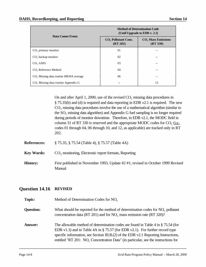
DAHS, Recordkeeping, and Reporting Section 14
Page 14-8 Acid Rain Program Policy Manual -- March 28, 2000
Data Comes From:
Method of Determination Code(Until Upgrade to EDR v. 2.1)
CO2 Pollutant Conc.(RT 202)
CO2 Mass Emissions(RT 330)
CO2 primary monitor 01 --
CO2 backup monitor 02 --
CO2 AMS 03 --
CO2 Reference Method 04 --
CO2 Missing data routine HB/HA average 06 --
CO2 Missing data routine Appendix G -- 13
On and after April 1, 2000, use of the revised CO2 missing data procedures in§ 75.35(b) and (d) is required and data reporting in EDR v2.1 is required. The newCO2 missing data procedures involve the use of a mathematical algorithm (similar tothe SO2 missing data algorithm) and Appendix G fuel sampling is no longer requiredduring periods of monitor downtime. Therefore, in EDR v2.1, the MODC field incolumn 31 of RT 330 is reserved and the appropriate MODC codes for CO2 (i.e.,codes 01 through 04, 06 through 10, and 12, as applicable) are tracked only in RT202.
References: § 75.35, § 75.54 (Table 4), § 75.57 (Table 4A)
Key Words: CO2 monitoring, Electronic report formats, Reporting
History: First published in November 1993, Update #2 #1; revised in October 1999 RevisedManual
Question 14.16 REVISED
Topic: Method of Determination Codes for NOx
Question: What should be reported for the method of determination codes for NOx pollutantconcentration data (RT 201) and for NOx mass emission rate (RT 320)?
Answer: The allowable method of determination codes are found in Table 4 in § 75.54 (forEDR v1.3) and in Table 4A in § 75.57 (for EDR v2.1). For further record typespecific information, see Section III.B.(2) of the EDR v2.1 Reporting Instructions,entitled "RT 201: NOx Concentration Data" (in particular, see the instructions for

Section 14 DAHS, Recordkeeping, and Reporting
Acid Rain Program Policy Manual -- March 28, 2000 Page 14-9
Column 30 of RT 201) and also refer to Section III.B.(20), entitled "RT 320: NOx
Emission Rate Data" (in particular, see the instructions for Column 53 of RT 320).
References: § 75.54 (Table 4), § 75.57 (Table 4A)
Key Words: Electronic report formats, NOx monitoring, Reporting
History: First published in November 1993, Update #2; revised in October 1999 RevisedManual
Question 14.17 REVISED
Topic: Reporting of Load Operating Levels
Question: How does an owner or operator of a unit performing a multi-load flow RATA reportoperating levels in RT 610, column 63, and RT 611, column 116?
Answer: In EDR v1.3, the normal load is indicated by using a letter code of "N" in RT 610/63and 611/116, instead of using the code "L", "M," or "H". However, in EDR v2.1, thenormal load is to be reported by using its actual letter code ("L", "M," or "H") in RT610/63 and RT 611/116, and using a normal load indicator flag of "N" in column 127of RT 611. For further discussion of reporting RATA load levels, see SectionIII.D.(6) of the EDR v2.1 Reporting Instructions, entitled "RTs 610 and 611: RelativeAccuracy Test Audit (RATA) and Bias Test Data and Results." In particular, see theinstructions for column 63 of RT 610 and columns 116 and 127 of RT 611.
References: § 75.56(a)(5)(iv)(D), § 75.59(a)(5)(ii)(E); Appendix A, Section 6.5.2
Key Words: Electronic report formats, RATAs, Reporting
History: First published in November 1993, Update #2; revised in October 1999 RevisedManual

DAHS, Recordkeeping, and Reporting Section 14
Page 14-10 Acid Rain Program Policy Manual -- March 28, 2000
Question 14.18 REVISED
Topic: Method of Determination Codes
Question: Which MODC codes identified in Table 4 of § 75.54 (corresponding to EDR v1.3)and Table 4A of § 75.57 (corresponding to EDR v2.1) are considered quality-assuredmonitor data for purposes of missing data substitution and availability calculations?
Answer: For Table 4 in § 75.54, MODC codes 01 through 04 and 14. For Table 4A, MODCCodes 01 through 04, 14, 16, 17, 19, and 20. Hours when these codes are used areconsidered quality-assured for missing data substitution purposes and for dataavailability calculations. Note that code 5, data from the parametric substitutionmethod, is excluded from these lists, because the parametric monitoring procedureswould be used instead of the missing data routine to calculate substitute values.
References: § 75.54 (Table 4), § 75.57 (Table 4A)
Key Words: Missing data, Recordkeeping, Reporting
History: First published in November 1993, Update #2; revised July 1995, Update #6; revisedin October 1999 Revised Manual
Question 14.19 REVISED
Topic: Quarterly Reporting -- Invalidation of Emissions Data
Question: What is EPA's policy on the invalidation of measured emissions data?
Answer: EPA’s policy on the invalidation of measured emissions data is found in SectionII.C.(3)(a) of the EDR v2.1 Reporting Instructions, entitled "Emissions Data fromCEMS."
References: § 75.64
Key Words: Electronic report formats, Reporting
History: First published in November 1994, Update #4; revised in October 1999 RevisedManual

Section 14 DAHS, Recordkeeping, and Reporting
Acid Rain Program Policy Manual -- March 28, 2000 Page 14-11
Question 14.20A REVISED
Topic: Quarterly Reporting -- Reporting of Operating Data
Question: What are the requirements for submitting operating records to EPA for the quarter?
Answer: The answer is found in Section III.B. of the EDR v2.1 Reporting Instructions, entitled"RT 300: Unit Operating Parameters."
References: § 72.96, § 75.64, § 75.54(b), § 75.57(b)
Key Words: Electronic report formats, Reporting
History: First published in November 1994, Update #4; revised in March 1997, Update #11;revised in October 1999 Revised Manual
Question 14.20B REVISED
Topic: Quarterly Reporting -- Reporting of Non-operating Units
Question: What are the requirements for submitting quarterly reports to EPA when the unit orstack did not operate?
Answer: The answer can be found in Section II.C.(14) of the EDR v2.1 Reporting Instructions,entitled "Data Reporting Requirements for Non-operating Quarters."
References: § 72.96, § 75.64
Key Words: Electronic report formats, Reporting
History: First published in November 1994, Update #4; revised in March 1997, Update #11;revised in October 1999 Revised Manual
DAHS, Recordkeeping, and Reporting Section 14
Page 14-12 Acid Rain Program Policy Manual -- March 28, 2000
Question 14.21 REVISED
Topic: Quarterly Reporting -- Interpretation of Operating Data
Question: How does EPA determine the operating status for a unit or stack in a given hour?
Answer: To determine the operating status of a unit or stack for a specific hour, EPA generallyrelies upon either the Unit Operating Time reported in column 18 of RT 300 (anyoperating time value greater than zero indicates unit operation during the hour) or thepresence of reported hourly emissions.
References: § 72.96, § 75.64
Key Words: Data validity, Electronic report formats, Reporting
History: First published in November 1994, Update #4; revised in October 1999 RevisedManual
Question 14.22 RETIRED
Question 14.23 RETIRED
Question 14.24 REVISED
Topic: Quarterly Reporting -- Submission of Records for Inappropriate Time Period
Question: How will EPA treat records in a quarterly file if the records represent hours for anotherquarter?
Answer: In general, emissions records will not be accepted for time periods outside the currentreporting quarter. However, for quality assurance records, there are limitedexceptions to this. For further discussion see Section II.C.(9) of the EDR v2.1Reporting Instructions, entitled "Reporting Data Outside the Reporting Period."
References: § 75.64

Section 14 DAHS, Recordkeeping, and Reporting
Acid Rain Program Policy Manual -- March 28, 2000 Page 14-13
Key Words: Electronic report formats, Reporting
History: First published in November 1994, Update #4; revised in October 1999 RevisedManual
Question 14.25 RETIRED
Question 14.26 REVISED
Topic: Quarterly Reports -- Missing Moisture Data
Question: If I report CO2 and SO2 on a dry basis or if I measure NOx concentration and diluenton an inconsistent moisture basis, I must measure and report an hourly moisture valuein either RT 220 (prior to April 1, 2000) or RT 212 (on and after April 1, 2000) tocalculate CO2 mass emissions, SO2 mass emissions, heat input and/or NOx emissionrate. How will EPA check the emissions and heat input calculations if the hourlymoisture value is missing?
Answer: The Emissions Tracking System (ETS) will attempt to re-calculate the reported hourlyemission rate and heat input rate values. If a moisture value is missing from RT 212 or220, ETS will generate an error message stating that the reported emissions rateand/or heat input rate cannot be re-calculated and the owner or operator is not using amoisture default reported in RT 531.
References: § 75.64
Key Words: Electronic report formats, Reporting
History: First published in November 1994, Update #4; revised in October 1999 RevisedManual

DAHS, Recordkeeping, and Reporting Section 14
Page 14-14 Acid Rain Program Policy Manual -- March 28, 2000
Question 14.27 REVISED
Topic: Quarterly Reporting -- Measured CO2 Concentration Values of Zero During BoilerStartup
Question: If the CEMS measures a CO2 concentration of zero during boiler unit startup, whatvalue should be used to calculate NOx emission rate?
Answer: Use the diluent cap value in such cases. See Section II.C.(3)(a)2 of the EDR v2.1Reporting Instructions, entitled "Data Entered or Edited Manually." Also see SectionIII.B.(20) of the EDR v2.1 Reporting Instructions, entitled "RT 320: NOx EmissionRate Data." In particular, see the instructions for column 14 of RT 320.
References: Appendix F
Key Words: CO2 monitoring, Electronic report formats, Reporting
History: First published in November 1994, Update #4; revised in October 1999 RevisedManual
Question 14.28 RETIRED
Question 14.29 RETIRED
Question 14.30 REVISED
Topic: Quarterly Submission of EDR Formatted Monitoring Plans
Question: When I submit a quarterly report, what monitoring plan data should be included?
Answer: The requirements for electronic monitoring plan submittals are given in § 75.53(c) and(d) for reporting in EDR v1.3, and in § 75.53(e) and (f) for reporting in EDR v2.1. Specific reporting guidance pertaining to each required monitoring plan data element isfound in Section III.C, "Monitoring Plan Records" in the EDR v2.1 ReportingInstructions. To ensure the completeness and quality of monitoring plan data, EPA has

Section 14 DAHS, Recordkeeping, and Reporting
Acid Rain Program Policy Manual -- March 28, 2000 Page 14-15
developed and released the Monitoring Data Checking Software (MDC) on the AcidRain Home Page: (URL: www.epa.gov/acidrain/cems/mdc/htm).
References: § 75.53, § 75.64
Key Words: Electronic report formats, Monitoring plans, Reporting
History: First published in November 1994, Update #4 as Question 10.9; renumbered asQuestion 14.30 in March 1995, Update #5; revised in October 1999 Revised Manual
Question 14.31 REVISED
Topic: Monitoring Plan Submitted with Quarterly Report File
Question: When the utility submits the monitoring plan (all of the required 500 level records) inthe quarterly report file, does the utility need to submit the monitoring plan in hardcopy? A monitoring plan checklist? A certification statement?
Answer: It is not necessary to submit a hardcopy version of the monitoring plan along with thequarterly report submittal. Sections 75.53(e) and (f) of the May 26, 1999 revisions toPart 75 clearly separate monitoring plan information into two categories, electronic andhardcopy. Section 75.62 explains when submittal of the electronic and hardcopyportions of the plan is required.
References: § 75.53, § 75.62
Key Words: Electronic report formats, Monitoring plan
History: First published in July 1995, Update #6; revised in October 1999 Revised Manual
Question 14.32 REVISED
Topic: Test Notification of Annual/Semiannual QA/QC RATAs
Question: For annual/semiannual QA/QC RATAs, what type of test notification does EPArequire? Should a utility submit a test notification form? A monitoring plan checklist?

DAHS, Recordkeeping, and Reporting Section 14
Page 14-16 Acid Rain Program Policy Manual -- March 28, 2000
Answer: For annual/semiannual QA/QC RATAs, EPA requires that a written test notice beprovided to the Administrator, to the EPA Regional Office and to the applicable Stateagency, in accordance with § 75.61(a)(5). No special form or format for the testnotification is required; however, at a minimum, the notice should indicate the affectedunit(s) to be tested, the type(s) of RATA(s) to be performed and the scheduled testdate(s). The written notification may be provided by regular mail or by facsimile. Theuse of electronic mail is acceptable if the respective State or EPA office agrees that thisis an acceptable form of notification. Note that under § 75.61(a)(5)(iii), theAdministrator, the EPA Regional Office or the State air pollution control agency mayissue a waiver from the RATA notification requirements for a unit or group of units, forone or more tests.
References: § 75.21, § 75.61(a)(5)
Key Words: Notice, RATAs
History: First published in July 1995, Update #6; revised in October 1999 Revised Manual
Question 14.33 REVISED
Topic: Reporting Results of Annual/Semiannual QA/QC RATAs
Question: For annual/semiannual QA/QC RATAs how should a utility report results to EPA? Electronically on a separate disk? Electronically in the quarterly report? By hardcopy?
Answer: Report these test results electronically in the quarterly report required under § 75.64. Also provide hardcopy RATA results to the applicable EPA Regional Office and/orState air pollution control agency, upon request. See also Section III.D of the EDRv2.1 Reporting Instructions, entitled "Quality Assurance and Certification DataReporting."
References: § 75.52, § 75.64(a) and (d)
Key Words: RATAs, Reporting
History: First published in July 1995, Update #6, revised in October 1999 Revised Manual
Section 14 DAHS, Recordkeeping, and Reporting
Acid Rain Program Policy Manual -- March 28, 2000 Page 14-17
Question 14.34 RETIRED
Question 14.35 RETIRED
Question 14.36 REVISED
Topic: Reporting of Partial Hours
Question: How do I account for SO2 and CO2 emissions and heat input rate during a partialoperating hour?
Answer: Account for partial operating hours when the quarterly cumulative tons of SO2 or CO2
is calculated. Before summing SO2 or CO2 mass emissions for the quarter, multiplyeach reported hourly SO2 or CO2 mass emission rate (i.e., lb/hr or tons/hr) by thecorresponding unit operating time in column 18 of RT 300, to convert it to a massvalue (lbs or tons).
For example, if a unit operated only for the first 12 minutes in a clock hour and tookSO2 readings once every minute, those 12 readings would be averaged and would bereported as the average hourly concentration in the RT 200. The hourly averagevolumetric flow rate in RT 220 would be calculated in the same way. These valueswould then be substituted into the appropriate equation (F-1 or F-2) to calculate thehourly SO2 mass emission rate reported in RT 310. Suppose, for the sake of thisexample, that the hourly SO2 and flow averages for the 12 minutes of unit operationare, respectively, 500 ppm and 25,000,000 scfh. Assuming that SO2 is measured ona wet basis, the hourly SO2 mass emission rate reported in RT 310 would be 2,075lbs/hr, according to Equation F-1. However, to indicate that the unit emitted SO2 atthis rate for only 12 minutes, you would report the unit operating time in RT 300,rounded to the nearest hundredth of an hour, as 0.20.
The product of the hour's SO2 mass emission rate in RT 310 and the unit operatingtime in RT 300 would then give the actual SO2 mass emitted during the partial unitoperating hour: (2,075 lbs/hr)(0. 20 hr) = 415 lbs. This would then be added to theproducts of the SO2 mass emission rates and the unit operating times for all of theother unit operating hours in the quarter and divided by 2,000 lbs/ton to determine thequarterly SO2 mass emissions (in tons) reported in RT 301.

DAHS, Recordkeeping, and Reporting Section 14
Page 14-18 Acid Rain Program Policy Manual -- March 28, 2000
The quarterly CO2 mass emissions and heat input should be reported and calculated inan analogous fashion (i.e., quantify the effects of partial unit operating hours only whenthe cumulative quarterly CO2 mass emissions and heat input values for RT 301 aredetermined).
Note: There is one exception to this. If the DAHS is programmed such that itperforms the calculation of SO2 mass or CO2 mass on an hourly basis and enters theresults into the new, optional data fields for SO2 mass (RT 310, column 35) and CO2
mass (RT 330, column 33), then the quarterly cumulative mass of SO2 or CO2 emittedis determined simply by summing all of the reported RT 310/35 or 330/33 values forthe quarter.
See also the "Field Descriptions and Instructions" for columns 16, 26, 62, and 72under "RT 301: Quarterly Cumulative Emissions Data (ARP)" in the EDR v2.1Reporting Instructions.
References: § 75.64(d); EDR v2.1 Reporting Instructions
Key Words: Electronic report formats, Reporting
History: First published in July 1995, Update #6; revised October 1996, Update #10; revisedin October 1999 Revised Manual
Question 14.37 REVISED
Topic: Reporting of Partial Hours
Question: There is a possible discrepancy between how utilities are reporting their SO2
emissions. There are two interpretations of what RT 310, column 18, "Average hourlySO2 mass emissions," should contain. For example, assume a unit runs averaging 150lb per hour. The unit only runs ½ hour. Should 150 lb/hr or 75 lb/hr be reported forthe SO2 mass emissions rate in RT 310, column 18?
Answer: Report the 150 lb/hr mass emission rate in column 18 of RT 310 and account for thepartial operating hour when calculating the quarterly cumulative mass of SO2 emitted. Alternatively, if the DAHS is programmed to calculate SO2 mass on an hourly basis,report the 150 lb/hr emission rate in column 18 of RT 310 and report an hourly massemissions value of 75 lb (not lb/hr) in column 35 of RT 310. See also the answer toQuestion 14.36.
References: § 75.64, RT 310

Section 14 DAHS, Recordkeeping, and Reporting
Acid Rain Program Policy Manual -- March 28, 2000 Page 14-19
Key Words : Data reduction, Electronic report formats
History: First published in November 1995, Update #7; revised in October 1999 RevisedManual
Question 14.38 REVISED
Topic: Reporting for Non-operating Affected Units
Question: If I submit an electronic quarterly report for an existing shutdown unit which does notyet have a Part 75 certified monitoring system, may I use an alternative certificationstatement?
Answer: An affected, non-retired unit which does not have certified CEMS because the unitwas shut down on the applicable certification deadline in § 75.4 and has not operatedsince is classified as a deferred unit. As of June 25, 1999 (the effective date of theMay 26, 1999 revisions to Part 75), the owner or operator of a deferred unit is notrequired to submit quarterly emissions reports for the unit until it re-commencescommercial operation (see § 75.64(a)).
References: § 75.64(a)
Key Words: Designated representative, Electronic report formats, Reporting
History: First published in November 1995, Update #7; revised in October 1999 RevisedManual
Question 14.39 REVISED
Topic: Reporting -- Diluent Cap
Question: Revisions to Appendix F of Part 75 allow us to calculate NOx emission rate bysubstituting a diluent cap CO2 concentration of 5.0% for boilers or 1.0% for turbinesor an O2 diluent cap concentration of 14.0% for boilers or 19.0% for turbines for ameasured CEM reading whenever the diluent concentration is below 5.0% CO2 forboilers or 1.0% for turbines or above 14.0% O2 for boilers or 19.0% for turbines. May we use this diluent cap only in calculating the NOx emission rate in lb/mmBtu (RT

DAHS, Recordkeeping, and Reporting Section 14
Page 14-20 Acid Rain Program Policy Manual -- March 28, 2000
320), and then use the actual measured CO2 concentration for calculating heat inputand CO2 mass emissions?
Answer: Yes, when the diluent cap is used for NOx emission rate, you may use the actualmeasured CO2 concentration for heat input rate and CO2 mass emission ratecalculations, because the diluent cap may only be used when a quality-assured diluentgas reading has been obtained. The reverse is also true (i.e., if you use the diluent capvalue for heat input rate and CO2 mass calculations, you need not use it to calculateNOx emission rate). Note, however, that for a particular hour, in which both the heatinput rate and CO2 mass emission rate are determined using CEMS, if the diluent capis used to calculate one of these parameters, it must also be used to calculate the other. (See also Section III.B.(3) of the EDR v2.1 Reporting Instructions, entitled "RT 202: CO2 Concentration Data (ARP).")
References: Appendix F, Sections 4.1, 4.4.1, 5.2.1, 5.2.2, 5.2.3, 5.2.4
Key Words: Diluent monitors, Reporting
History: First published in November 1995, Update #7; revised in October 1999 RevisedManual
Question 14.40 REVISED
Topic: Reporting -- Diluent Cap
Question: Revisions to Appendix F of Part 75 allow us to calculate NOx emission rate bysubstituting a diluent cap CO2 concentration of 5.0% for boilers or 1.0% for turbinesor an O2 diluent cap concentration of 14.0% for boilers or 19.0% for turbines for ameasured CEM reading whenever the diluent concentration is below 5.0% CO2 forboilers or 1.0% for turbines or above 14.0% O2 for boilers or 19.0% for turbines. Are hours when the diluent cap value is substituted for a CEM value consideredmissing data, resulting in lower percent monitor data availability for NOx emission rate?
Answer: No. You may only use the diluent cap during periods when the diluent monitor ismeasuring valid, quality-assured data. Therefore, as with any hours of valid, quality-assured data, these hours count as quality-assured data to go in the lookback periodfor substitute data and they count as quality-assured hours for purposes of calculatingavailability. If the diluent monitor is not measuring valid, quality-assured data, use themissing data procedures in subpart D of Part 75 (§ 75.31 or § 75.33 for NOx,§ 75.31 or § 75.35 for CO2, and § 75.36 for heat input rate).
Section 14 DAHS, Recordkeeping, and Reporting
Acid Rain Program Policy Manual -- March 28, 2000 Page 14-21
References: §§ 75.31, 75.33, 75.35, and 75.36; Appendix F, Sections 4.1, 4.4.1, 5.2.1, 5.2.2,5.2.3, 5.2.4, 5.3.5
Key Words: Diluent monitors, Missing data, Reporting
History: First published in November 1995, Update #7; revised in October 1999 RevisedManual
Question 14.41 REVISED
Topic: Reporting -- Diluent Cap
Question: Revisions to Appendix F of Part 75 allow us to calculate NOx emission rate bysubstituting a diluent cap CO2 concentration of 5.0% for boilers or 1.0% for turbinesor an O2 diluent cap concentration of 14.0% for boilers or 19.0% for turbines for ameasured CEM reading whenever the diluent concentration is below 5.0% CO2 forboilers or 1.0% for turbines or above 14.0% O2 for boilers or 19.0% for turbines. What should be the method of determination code in RT 320 for a NOx system whenthe diluent cap is used? What should be the method of determination code in RT 202for CO2 concentration and for RT 330 for CO2 mass emissions?
Answer: Use a method of determination code (MODC) of "14" in RT 320 (for NOx). Thiscode indicates an hour in which the NOx emission rate was calculated using measuredNOx concentration (RT 201) and the diluent cap. Regarding the appropriate reportingin RTs 202 and 330 when the diluent cap is used, it depends upon which EDR versionis being used, as indicated below:
For EDR v1.3: The EPA prefers that utilities report the actual monitor reading forcalculating CO2 mass emissions and heat input rather than a diluent cap value. Forthese hours in which the actual values are used, the MODC in RT 202 would be "01"or "02". If the diluent cap is used for reporting the CO2 concentration in RT 202, thenuse the MODC of "14" in RT 202. Leave the method of determination code blank forRT 330 (for CO2 mass emissions). Note that you should fill in the method ofdetermination code in RT 330 only when using Appendix G missing data procedures. Note that reporting in EDR v1.3 will no longer allowed after April 1, 2000. Version2.1 must be used on and after that date.
For EDR v2.1: When the diluent cap value is used to determine CO2 mass emissions,always report the actual measured CO2 concentration in RT 202, using an appropriateMODC (i.e., 01, 02, 03, or 04). Do not report a MODC of 14 in RT 202. Instead,indicate by means of a "Y" flag in column 43 of RT 330 that the diluent cap value is

DAHS, Recordkeeping, and Reporting Section 14
Page 14-22 Acid Rain Program Policy Manual -- March 28, 2000
being used to calculate CO2 mass emissions for the hour. (See also Section III.B.(20),entitled "RT 320: NOx Emission Rate Data" and Section III.B.(3), entitled "RT 202: CO2 Concentration Data (ARP)" in the EDR v2.1 Reporting Instructions). The use ofEDR v2.1 is mandatory, beginning on April 1, 2000.
References: Appendix F, Sections 4.1, 4.4.1, 5.2.1, 5.2.2, 5.2.3, 5.2.4
Key Words: Diluent monitors, Reporting
History: First published in November 1995, Update #7; revised in October 1999 RevisedManual
Question 14.42 RETIRED
Question 14.43 RETIRED
Question 14.44
Topic: CO2 Emission Reporting
Question: Confirm the following assumptions regarding CO2 emission reporting for gas and oil-fired units:
(1) If Equation G-4 is used for oil, report CO2 due to oil in tons/day in RT 331.
(2) If Equation G-4 is used for gas, report CO2 due to gas in tons/hr in RT 330.
(3) If Equation G-1 is used for gas and oil, report CO2 total (gas+oil) in RT 331.
Answer: (1) Equation G-4 may only be used for gas-fired units as defined in § 72.2. Oil-firedunits using fuel sampling and analysis to determine CO2 mass emissions should useEquation G-1 and report daily in RT 331.
(2) Gas-fired units using Eq. G-4. A gas-fired unit using Equation G-4 to providehourly CO2 mass emissions based upon heat input should report in RT 330. Thiswill be true whether the gas-fired unit is combusting oil or gas.

Section 14 DAHS, Recordkeeping, and Reporting
Acid Rain Program Policy Manual -- March 28, 2000 Page 14-23
(3) Units using Appendix G (Eq. G-1) all the time . A unit using Equation G-1 ofAppendix G to determine CO2 mass emissions by fuel sampling and analysisshould report daily in RT 331. This will be true no matter what fuel is combusted. If the unit combusts more than one fuel in a day, determine the total CO2 massemissions for the day from all fuels and report this in RT 331.
References: § 72.2, § 75.54(e)(2), § 75.57(e)(2); Appendix G, Section 2
Key Words : CO2 monitoring, Electronic report formats, Gas-fired units
History: First published in November 1995, Update #7
Question 14.45 RETIRED
Question 14.46 REVISED
Topic: Reporting Heat Input -- Multiplication by Operating Time and Fuel Usage Time
Question: For Appendix E recordkeeping, do we multiply the fuel usage time by the hourly heatinput rate to determine total hourly heat input prior to reading off of the NOx
correlation curve?
Answer: For Appendix E, use the unfactored heat input rate to determine the NOx emission ratealong the NOx/heat input correlation curve. If you burn multiple fuels in an hour, thenuse the total heat input for each fuel for the hour (heat input rate multiplied by fuelusage time) in calculating the average NOx emission rate for the unit for the hour (seeEquation E-2). See also the instructions for RTs 323, 324, and 325 in SectionsIII.B.(23), (24), and (25) of the EDR v2.1 Reporting Instructions.
References: Appendix E, Sections 3.3.4, 2.4.1, and 2.4.3
Key Words: Excepted methods, Heat input, NOx monitoring, Reporting
History: First published in November 1995, Update #7; revised in October 1999 RevisedManual

DAHS, Recordkeeping, and Reporting Section 14
Page 14-24 Acid Rain Program Policy Manual -- March 28, 2000
Question 14.47 REVISED
Topic: Reporting Heat Input -- Multiplication by Operating Time and Fuel Usage Time
Question: When reporting heat input on an hourly basis in RT 300, do we report the unfactoredheat input rate, or the factored total heat input (heat input rate multiplied by unitoperating time)? Please reply also for Appendix D sources, during single and dual fuelhours.
Answer: In RT 300, column 36, report the unfactored heat input rate in mmBtu/hr. Considerthe unit operating time only when calculating the cumulative heat input for the quarter.To calculate cumulative quarterly heat input, multiply each hourly heat input rate in RT300, column 36 by the corresponding unit operating time in RT 300, column 18, andthen take the sum of these products. Note that there is one exception to this. If theDAHS is programmed to calculate heat input (in mmBtu) on an hourly basis, you mayreport both heat input rate (column 36) and the heat input (column 57) for the hour inRT 300. If you report heat input in RT 300/57, simply sum these hourly values at theend of the quarter to obtain the cumulative quarterly heat input.
For an Appendix D source, during a single fuel hour, the heat input rate in RT 302/45or RT 303/45 should be the same as the heat input rate in RT 300/36 for the hour. The fuel usage time in RT 302/52 or RT 303/52 should be identical to the unitoperating time in RT 300/18.
For an Appendix D source, during a multiple fuel hour, it will be necessary todetermine an average heat input rate for the hour. This requires multiplying the heatinput rate in RT 302/45 or 303/45 by the corresponding fuel usage time in RT 302/52or RT 303/52 for a given fuel, to obtain the hourly heat input for the fuel. Then add theindividual hourly heat inputs from each fuel and divide this sum by the unit operatingtime in RT 300/18 to get the unit heat input rate to enter into RT 300/36. See alsoSection III.B.(11), entitled "RT 300: Unit Operating Parameters" in the EDR v2.1Reporting Instructions.
References: § 75.57(b), § 75.58(c), § 75.64; Appendix D
Key Words: Electronic report formats, Excepted methods, Heat input
History: First published in November 1995, Update #7; revised in October 1999 RevisedManual

Section 14 DAHS, Recordkeeping, and Reporting
Acid Rain Program Policy Manual -- March 28, 2000 Page 14-25
Question 14.48 REVISED
Topic: Appendix E -- Monitoring Plan, RT 520 Requirements
Question: Have the formula verification requirements for Appendix E certification changed underthe May 26, 1999 revisions to Part 75?
Answer: Yes. Appendix E formulas are no longer required in an Appendix E certificationapplication. The required Appendix E formula verification procedure is described initem (4) of Question 26.5. Note that when you begin reporting data in EDR v2.1, youmust report multiple RTs 560, to define the NOx correlation curve segments. (Seealso Section III.C.(20) of the EDR v2.1 Reporting Instructions, entitled "RT 560: Monitoring System Recertification, Maintenance, or Other Events.")
References: Appendix E, Section 3
Key Words: Excepted methods, Monitoring plan, NOx monitoring
History: First published in November 1995, Update #7; revised in October 1999 RevisedManual
Question 14.49 REVISED
Topic: Appendix D Reporting -- Method of Determination Codes
Question: For RT 302 (field starting in column 31), code "3" is indicated as being for maximumfuel flow rate. Is this the maximum observed or maximum potential flow rate? Forconsistency with substitution it would be the maximum observed. Is this correct?
Answer: No. Use code "3" for the maximum potential flow rate. If you are reporting themaximum fuel flow rate in a load range (for multiple fuel hours), use code "1." This isthe code for substitute data. (See also Section III.B.(13) in the EDR v2.1 ReportingInstructions, entitled "RT 302: Oil Fuel Flow".)
References: Appendix D, Section 2.4.2
Key Words: Electronic report formats, Excepted methods, Reporting
History: First published in November 1995, Update #7; revised in October 1999 RevisedManual
DAHS, Recordkeeping, and Reporting Section 14
Page 14-26 Acid Rain Program Policy Manual -- March 28, 2000
Question 14.50 RETIRED
Question 14.51 REVISED
Topic: Electronic Reports -- Editing Data
Question: Please clarify various Agency references to editing negative emission values that maybe recorded. Under startup and shutdown conditions, the recording of negativeemission values is possible, but reporting of negative values is not permitted by theAgency. Can the negative emission values manually be changed to zero?
Answer: In general, when negative emissions or percent moisture values are recorded duringstartup and shutdown you may replace them manually with zeros. When you replace anegative value with zero, you must also report MODC "21" for the affected gasconcentration (except for CO2), percent moisture, and, if applicable, NOx emissionrate in the appropriate EDR record types (RTs 200, 201, 212, and 320). MODC"21" may be manually entered.
For negative CO2 values recorded during startup and shutdown, replace these with thediluent cap value instead of zero, to avoid reporting heat input rates of zero while theunit is operating. For a further discussion, see Section II.C.(3)(a)(2) of the EDR v2.1Reporting Instructions, entitled "Data Entered or Edited Manually."
References: EDR v2.1 Reporting Instructions
Key Words : Data reduction, Electronic report formats, Reporting
History: First published in November 1995, Update #7; revised in October 1999 RevisedManual
Question 14.52 REVISED
Topic: Electronic Report Formats -- Multiple Fuels
Question: In RT 302 (and 303), would the Single/Multiple Fuel flag be "M" if one type of gasand one type of oil were combusted, or is "M" to indicate that more than one type ofgas (or oil) was combusted?

Section 14 DAHS, Recordkeeping, and Reporting
Acid Rain Program Policy Manual -- March 28, 2000 Page 14-27
Answer: If more than one type of fuel (for example, oil and gas, or diesel oil and residual oil) iscombusted during an hour, then "M" must be entered in RT 302, column 89 and/or RT303, column 59. This information is necessary to implement Appendix D fuelflowmeter missing data procedures which require a look back to single-fuel hours to fillin for missing data when one fuel is combusted and a look back to multiple fuel hourswhen multiple fuels are combusted. See also Section III.B.(13), in the EDR v2.1Reporting Instructions, entitled "RT 302: Oil Fuel Flow" and Section III.B.(14),entitled "RT 303: Gas Fuel Flow."
References: § 75.64; Appendix D, Sections 2.4.2.2 and 2.4.2.3; EDR v2.1
Key Words : Electronic report formats, Missing data
History: First published in November 1995, Update #7; revised in October 1999 RevisedManual
Question 14.53 REVISED
Topic: Fuel Usage Reporting
Question: If gas is burned for the first 20 minutes of an hour and oil and gas are co-fired for theremaining 40 minutes, are the fuel usage times for gas and oil reported as "1.00" and "0.67", respectively, even though the fuel usage times do not add up to 1.00?
Answer: Yes. See also Section III.B.(13) of the EDR v2.1 Reporting Instructions, entitled "RT302: Oil Fuel Flow" and Section III.B.(14), entitled "RT 303: Gas Fuel Flow."
References: § 75.64
Key Words : Data reduction, Reporting
History: First published in November 1995, Update #7; revised in October 1999 RevisedManual
DAHS, Recordkeeping, and Reporting Section 14
Page 14-28 Acid Rain Program Policy Manual -- March 28, 2000
Question 14.54 REVISED
Topic: Monitoring Plans -- Electronic Submission
Question: Our understanding is that the entire monitoring plan must be submitted in eachelectronic quarterly report. Does this mean that the monitoring plans for all units at aplant, regardless of association with each other, must be submitted in a single EDR file? For instance, if a plant has a common stack CS12 for units 1 and 2, a single stack unit3, and multiple stacks MS4A and MS4B for unit 4, should all of these monitoring planrecords be reported in the same data file? If so, what is the sort order?
Answer: No. The monitoring plan records for all of these units should NOT be in the same datafile. Include only the complete monitoring plan data records for the appropriate unit(s)in the one quarterly data file submitted for that (those) unit(s). In the example, theutility would submit one file which would include all of the appropriate data for CS12,unit 1, and unit 2, including the hourly records, monitoring plan records, and qualityassurance records in the standard record type order. A separate file would besubmitted for unit 3. An additional separate file would be submitted which includes allof the appropriate data for MS4A, MS4B, and unit 4. See also Section II.B.(1) of theEDR v2.1 Reporting Instructions, entitled "File Content."
References: § 75.64
Key Words : Monitoring plan, Reporting
History: First published in November 1995, Update #7; revised in October 1999 RevisedManual
Question 14.55 RETIRED
Question 14.56 RETIRED
Question 14.57 RETIRED
Section 14 DAHS, Recordkeeping, and Reporting
Acid Rain Program Policy Manual -- March 28, 2000 Page 14-29
Question 14.58 REVISED
Topic: Electronic Report Formats -- CO2 Performance Specifications
Question: Alternative Performance Specification Flag - RTs 230, 600 and 602. A unit is notconsidered a low emitter of SO2 or NOx under Section 2.3.1.2(e) or (f) of AppendixB; however, it does use the alternative CO2 calculation for daily calibration error and7-day calibration error tests, and linearity tests. Should the "1" or "0" flag be used?
Answer: For daily and 7-day calibration error tests of a CO2 monitor, there is actually noalternative performance specification. Section 3.1 of Appendix A to Part 75 specifiesthat the calibration error of a CO2 monitor is always expressed in percent CO2, ratherthan as a percentage of span. This is considered to be the normal calibration errorspecification and should have a "0" flag in RT 230 and 600. The alternate specificationflag in these record types applies only to SO2 and NOx pollutant concentrationmonitors at facilities that are low emitters, under Section 2.3.1.2(e) or (f) of AppendixB, of those pollutants.
Regarding linearity tests, however, Section 3.2 of Appendix A clearly identifies both anormal and an alternative performance specification for CO2 monitors. The alternativespecification is available to all sources, regardless of their emission levels, and may beused at any of the three levels (L, M, or H) of the linearity test. If the normal linearityspecification (5% of the reference value) is used, then report a "0" flag in RT 602. Ifthe alternative specification (absolute value of R-A # 0.5 % CO2) is used, report a "1"flag in RT 602.
See also Section III.B.(8) of the EDR v2.1 Reporting Instructions, entitled "RT 230: Daily Calibration Test Data and Results" and Section III.D.(1), entitled "RT 600: 7-Day Calibration Error Test Data and Results."
References: Appendix A, Sections 3.1 and 3.2; Appendix B, Sections 2.3.1.2(e) and (f)
Key Words : Calibration error, CO2 monitoring, Electronic report formats, Linearity
History: First published in November 1995, Update #7; revised in October 1999 RevisedManual
Question 14.59 RETIRED
DAHS, Recordkeeping, and Reporting Section 14
Page 14-30 Acid Rain Program Policy Manual -- March 28, 2000
Question 14.60 REVISED
Topic: Reporting a Bias Adjustment Factor for CO2 Monitoring
Question: The regulations do not require a bias test for the CO2 monitoring system. Section75.59(a)(5)(iii)(G) states to report a bias adjustment factor of "1.000 for anymonitoring system that passed the bias test." Is it correct to report a bias adjustmentfactor (BAF) of 1.000 in RT 611 for the CO2 monitoring system, even though a biastest was not performed?
Answer: Yes. Report a BAF of 1.000 in RT 611, column 111 for the CO2 monitoring system. See also Section III.D.(6) in the EDR v2.1 Reporting Instructions, entitled "RT 611: RATA and Bias Test Results."
References: § 75.59(a)(5)(iii)(G)
Key Words : Bias, CO2 monitoring, Electronic report formats
History: First published in November 1995, Update #7; revised in October 1999 RevisedManual
Question 14.61 REVISED
Topic: When to Submit RT 550 (Reasons for Missing Data Periods)
Question: When should RT 550 be submitted?
Answer: RT 550 was originally created to allow electronic submission of a portion of thecompliance certification requirement at § 75.64(c), which required submittal of the "...measures taken to cure the causes for the missing data periods." However, the May26, 1999 revisions to Part 75 removed this requirement from the rule. Therefore,submittal of this record type is optional.
References: § 75.64(a)(2)(vi), § 75.64(c)
Key Words: Missing Data, Reporting
History: First published in November 1995, Update #7; revised in October 1999 RevisedManual

Section 14 DAHS, Recordkeeping, and Reporting
Acid Rain Program Policy Manual -- March 28, 2000 Page 14-31
Question 14.62 REVISED
Topic: Ordering of RT 550
Question: How should we order RTs 550? We would prefer to print all RTs 550 for a givenparameter, then move on to the next parameter. This would mean a recordordering by parameter, then by date/time.
Answer: The proposed ordering by parameter is acceptable.
References: § 75.64; EDR v2.1
Key Words : Electronic report formats, Monitoring plan
History: First published in November 1995, Update #7; revised in October 1999 RevisedManual
Question 14.63 REVISED
Topic: RT 550 Reason Codes
Question: Adding the new reason codes for downtime for RT 550 can be done in a variety ofways. Will it be okay to include this analysis and provision to enter reasons insoftware which is run at the end of each quarter? In other words, can the current realtime database design be left alone?
Answer: It is not necessary to have this information electronically as part of the real timedatabase. For example, the information in RT 550 may be generated in anothersoftware program and then merged into the quarterly report at the end of the quarter. In the event of a site visit, missing data reasons should be available in some form (e.g.,CEM log, maintenance log, hardcopy).
References: § 75.64; EDR v1.3
Key Words: Electronic report formats, Missing data, Reporting
History: First published in November 1995, Update #7

DAHS, Recordkeeping, and Reporting Section 14
Page 14-32 Acid Rain Program Policy Manual -- March 28, 2000
Question 14.64
Topic: Effect of Off-line Hours on RTs 550
Question: Previously, EPA has provided guidance indicating that if a unit were down for a fewhours in the middle of a missing data event, the period should be treated as a singlemissing data gap (and the offline hours should not be included in the determination ofthe gap length). In a situation like this, should only one RT 550 record be created torepresent the missing data gap that happened to include a number of hours in which theunit was not operating, or should multiple records be created?
Answer: Create only one RT 550 record, so long as the missing data gap does not extend intothe next calendar quarter. If the missing data gap does extend into the next calendarquarter, then follow the procedures described in Policy Manual Question 14.66.
References: § 75.64; EDR v2.1
Key Words : Electronic report formats, Missing data, Reporting
History: First published in November 1995, Update #7
Question 14.65 REVISED
Topic: Effect of Overlapping Missing Data on RTs 550
Question: If CO2 data becomes invalid at time "0," RTs 550 for the affected CO2 and NOx-diluent monitoring systems would have to be created. If at time "1" later (while CO2 isstill invalid), data from the NOx analyzer becomes invalid, should another RT 550 becreated for the NOx-diluent system? If so, would the end time of the first NOx recordbe equal to the hour the CO2 data became valid, and would the end time of the secondNOx record be equal to the hour the NOx (ppm) data became valid?
Answer: No. Create just one RT 550 for the NOx-diluent system and report one RT 550 forthe CO2 system. The NOx missing data period extends from time "0" (when the CO2
monitor data becomes invalid) until both NOx and CO2 again become valid. Thereason for the NOx missing data period should describe the event that initially causedthe NOx lb/mmBtu data to be invalidated.
References: § 75.64; EDR v2.1

Section 14 DAHS, Recordkeeping, and Reporting
Acid Rain Program Policy Manual -- March 28, 2000 Page 14-33
Key Words : Electronic report formats, Missing data, Reporting
History: First published in November 1995, Update #7; revised in October 1999 RevisedManual
Question 14.66 REVISED
Topic: Effect of a Quarter Boundary on RTs 550
Question: Previously there was detailed guidance provided on how to run missing data for anevent that overlaps a quarter boundary. Should RT 550 records be treated in a similarmanner? Three options seem reasonable: (1) a single RT 550 is reported with actualbegin and end times (when would it be reported?); (2) one RT 550 is reported withactual begin and quarter end times, followed by another RT 550 (reported nextquarter) with quarter begin time and actual end time; or (3) one RT 550 is reportedwith actual begin and quarter end times, followed by another RT 550 (reported nextquarter) with actual begin time and actual end time. What treatment would beappropriate?
Answer: The second option. Report one RT 550 with the actual beginning time of the missing
data period and the quarter end time. Then in the next quarter, report another RT 550with the beginning time for the quarter and the actual end time of the missing dataperiod.
References: § 75.64; EDR v2.1
Key Words : Electronic report formats, Missing data, Reporting
History: First published in November 1995, Update #7; revised in October 1999 RevisedManual
Question 14.67 RETIRED
Question 14.68 RETIRED

DAHS, Recordkeeping, and Reporting Section 14
Page 14-34 Acid Rain Program Policy Manual -- March 28, 2000
Question 14.69
Topic: RT 550 End Time
Question: If hours 01:00 and 02:00 are missing some piece of data (e.g., SO2 ppm), it seemsobvious that the Begin Hour field (column 23) of the RT 550 should be "01." Shouldthe End Hour field (column 31) be "02" representing the last bad hour, or "03"representing the first good hour?
Answer: Report the End Hour field as "02," the last hour of the missing data period.
References: § 75.64; EDR v2.1
Key Words : Electronic report formats, Missing data, Reporting
History: First published in November 1995, Update #7
Question 14.70 RETIRED
Question 14.71 RETIRED
Question 14.72
Topic: Minimum Data Acquisition and Handling System Requirements
Question: What are the minimum requirements for a Data Acquisition and Handling System,particularly for Appendix D and/or E units?
Answer: The Data Acquisition and Handling System (DAHS) must electronically capture data,perform calculations, and produce electronic reports in the Electronic Data Reporting(EDR) format, as specified in Appendix A, Section 4. Note that a DAHS may havemore than one component, as long as the multiple components are identified in themonitoring plan.

Section 14 DAHS, Recordkeeping, and Reporting
Acid Rain Program Policy Manual -- March 28, 2000 Page 14-35
For Appendix D and/or E units, the DAHS system can be very simple. For example,the utility may have a multiple component DAHS, where the first component is asimple recording device which electronically captures the data from the fuel flow meter,and the second component is a commercially available spreadsheet program run on aPC with a small number of customized programming commands within the spreadsheetprogram to assist in the report generation. Because the fuel sampling and analysis data(% sulfur, GCV) is manually captured, it may be manually entered into thespreadsheet. The spreadsheet would then be customized to perform formula andmissing data calculations (see Question 14.73), and to produce the ASCII flat filespecified by the EDR format. The utility could then use the EPA developed softwareprogram, ETS-PC, to ensure that the quarterly report files are in the correct EDRformat.
References: Appendix A, Section 4
Key Words: DAHS, Excepted methods
History: First published in November 1995, Update #7
Question 14.73 REVISED
Topic: Data Acquisition and Handling System -- Minimum Requirements for Missing Data
Question: Are there any exceptions to the minimum requirements for a Data Acquisition andHandling System, particularly for Appendix D and/or E units?
Answer: Yes. As described in Question 14.72, an Appendix D and/or E unit could use asimple DAHS, consisting primarily of a commercially available spreadsheet. However,EPA recognizes that the missing data calculations may be difficult to program within aspreadsheet environment. Therefore, for peaking units (as defined in § 72.2) usingAppendix D and/or Appendix E, EPA will consider petitions (which may be submittedwith the certification or recertification application) to use maximum potential fuel flowrate instead of following the load based missing data procedures outlined in the rule. Inthe monitoring plan with the petition, in RT 507, provide capacity factor information forthree calendar years to demonstrate that the unit meets the definition of a peaking unitin § 72.2.
For all parameters other than fuel flow rate, use the missing data procedures specifiedin Part 75. For additional guidance see Questions 15.12 and 15.19.
References: Appendix A, Section 4

DAHS, Recordkeeping, and Reporting Section 14
Page 14-36 Acid Rain Program Policy Manual -- March 28, 2000
Key Words: DAHS, Excepted methods, Missing data
History: First published in November 1995, Update #7; revised in October 1999 RevisedManual
Question 14.74 RETIRED
Question 14.75
Topic: Validation of Stored Data during DAHS Downtime
Question: Data Acquisition and Handling Systems (DAHS) are often made up of multiplecomponents such as a Programmable Logic Controller (PLC), which does limited dataprocessing and short term data storage, and a PC, which does more complete dataprocessing and long term data storage. Because of this, it may be possible to collectand store raw data during a DAHS downtime and complete the processing of that datawhen the complete DAHS is running again. For example, this might occur during theinstallation of upgraded software or when a PC crashes. May we collect and storeraw data in a component such as a PLC during a DAHS downtime and then completeprocessing of the data when the complete DAHS system is operating again? If so,would our data be considered valid if the reason for the DAHS downtime is a changeto the DAHS that requires recertification?
Answer: Yes. It is acceptable to store raw data during a period when the complete DAHS isnot available (e.g., during installation and DAHS verification testing for a new softwareversion or when the DAHS PC crashes) and later complete processing of that data inthe DAHS and report that data as valid during the entire time that the DAHS wasunavailable, as long as the raw data (including any necessary quality assurance data)are:
(1) Quality-assured based on all other applicable criteria (e.g., daily calibration hasbeen passed);
(2) Stored electronically in a component (e.g., PLC, data logger) that is identified inthe data pathway diagram (in the monitoring plan) of a certified system; and
(3) Captured, stored, and transferred electronically.
Section 14 DAHS, Recordkeeping, and Reporting
Acid Rain Program Policy Manual -- March 28, 2000 Page 14-37
If the software is being upgraded, but the data storage component is not affected, datamay be collected and stored in the storage component while the missing data andformula verification tests are run on the software. As long as those tests are passed,the data collected and stored in the storage component may be processed by thenewly certified DAHS component and may be considered valid. Please note,however, that if the storage component (e.g., PLC, data logger) is also being modifiedor replaced, data may not be stored on the new or modified component until after therecertification tests are completed.
References: § 75.10(a)
Key Words: DAHS, Recertification
History: First published in March 1996, Update #8
Question 14.76 RETIRED
Question 14.77 RETIRED
Question 14.78 RETIRED
Question 14.79 RETIRED
Question 14.80 REVISED
Topic: Reporting during Gas-only Hours
Question: EPA has revised § 75.11(e) to allow the reporting of SO2 concentration from an SO2
CEMS during hours when the unit is combusting only gas. The revised rule requiresreporting of a default value of 2.0 ppm whenever the SO2 hourly average valuerecorded by the CEMS is less than 2.0 ppm. How is reporting to be implemented inRTs 200 and 310? Should the 2.0 ppm be reported as an unadjusted value directly

DAHS, Recordkeeping, and Reporting Section 14
Page 14-38 Acid Rain Program Policy Manual -- March 28, 2000
from the monitor or as a bias-adjusted value? Is there a different method ofdetermination code for hours when the 2.0 ppm default value is reported?
Answer: Report the default value only when the bias-adjusted hourly average SO2
concentration is less than 2.0 ppm. Leave the unadjusted SO2 concentration in column29 of RT 200 blank when the default is reported. Report the 2.0 ppm value as thebias-adjusted SO2 concentration in column 35 of RT 200. Use a method ofdetermination code of "16" when the 2.0 ppm default value is reported. See alsoSection III.B.(1) of the EDR v2.1 Reporting Instructions, entitled "RT 200: SO2
Concentration Data (ARP)" and Section III.B.(17), entitled "RT 310: SO2 MassEmissions Data (ARP)."
References: § 75.11(e)
Key Words: Electronic data reporting, Gas-only hours, SO2 monitoring
History: First published in October 1996, Update #10; revised in October 1999 RevisedManual
Question 14.81 REVISED
Topic: Calculation of Heat Input Rate
Question: Should we use bias-adjusted flow rates to calculate and report heat input rate in RT300?
Answer: Yes. Use the bias-adjusted flow rate when calculating heat input rate using equationsF-15, F-16, F-17, and F-18. Report that heat input rate value in RT 300 for eachhour. EPA considers the bias-adjusted values to be the official values for determiningcompliance for emissions and heat input under the Acid Rain Program. See alsoSection III.B.(11) of the EDR v2.1 Reporting Instructions, entitled "RT 300: UnitOperating Parameters."
References: Appendix F, Section 5.2
Key Words: Bias adjustment factor, Calculations, Heat input
History: First published in October 1996, Update #10; revised in October 1999 RevisedManual

Section 14 DAHS, Recordkeeping, and Reporting
Acid Rain Program Policy Manual -- March 28, 2000 Page 14-39
Question 14.82 REVISED
Topic: Calculation of Quarterly and Annual NOx Emission Rates
Question: According to Equations F-9 and F-10 of Part 75, quarterly and annual NOx emissionrates should be calculated as a straight arithmetic average (i.e., the hourly NOx
emission rates should be summed and divided by the number of hourly NOx emissionrates during the quarter or the year, and should not be weighted by unit operatingtime). According to other EPA guidance, it appears that the quarterly and annual NOx
emission rates should be calculated as a time-weighted average (i.e., the product of thehourly NOx emission rates and the hourly operating time should be summed anddivided by the total hourly operating time). Which method is correct?
Answer: The correct method is to calculate the quarterly or annual average NOx emission rateas a straight arithmetic average using Equations F-9 and F-10. This is the method thatEPA will use to determine compliance with Part 76 NOx emission limits. Thissupersedes all previous Agency guidance to the contrary. See also Section III.B.(12)of the EDR v2.1 Reporting Instructions, entitled "RT 301: Quarterly CumulativeEmissions Data (ARP)."
References: Appendix F, Section 3
Key Words: NOx emission rates, Reporting
History: First published in October 1996, Update #10; revised in October 1999 RevisedManual
Question 14.83 RETIRED
Question 14.84 REVISED
Topic: Quality Assurance RATA Notification
Question: Is EPA's Clean Air Markets Division allowing a waiver from the requirement in§ 75.61 to notify ARD of the date of periodic quality assurance RATAs?
Answer: Yes. Effective February 28, 1997, the Clean Air Markets Division has issued awaiver from the requirement to notify the Administrator (or Administrator's delegatee,

DAHS, Recordkeeping, and Reporting Section 14
Page 14-40 Acid Rain Program Policy Manual -- March 28, 2000
ARD) of the date of periodic relative accuracy testing under § 75.61(a)(5). Thiswaiver shall continue until the Agency issues guidance otherwise. This policy does notwaive the requirement to notify the Administrator for certification/recertification RATAtesting.
Note that the requirements to notify EPA Regional Offices or State or local agenciesremain in effect, unless those respective agencies also issue a waiver.
References: § 75.21(e), § 75.61(a)(5)
Key Words: Notice, RATAs
History: First published in March 1997, Update #11; revised in October 1999 Revised Manual
Question 14.85
Topic: Rule Revision -- Impact on Certification Testing Software
Question: Are the Part 75 revisions expected to impact software certification testing softwaresuch as DCAS?
Answer: DCAS is designed for EDR v1.3 and the old rule. Thus, DCAS cannot be used tocompletely perform EDR v2.1 DAHS verification since the missing data subroutinesfor CO2, heat input, NOx concentration, and moisture are different from the old rule.
References: N/A
Key Words: DCAS
History: First published in October 1999 Revised Manual
Question 14.86
Topic: Update to DCAS
Question: Is there any plan in the works to update or revise the DCAS or any other CEMSsoftware certification (verification testing) programs, tool or related testingrequirements?
Section 14 DAHS, Recordkeeping, and Reporting
Acid Rain Program Policy Manual -- March 28, 2000 Page 14-41
Answer: There is no plan at this time to update DCAS. Upon converting to EDR v2.1, ownersor operators (or their software vendors) must devise tests to check that the missingdata algorithms are functioning properly. Likewise, checks must be made to ensurethat proper equations are used to compute hourly averages for SO2, NOx, CO2, heatinput, and moisture for each formula submitted in RT 520. The DesignatedRepresentative (DR) or AAR must submit the following certification statements eitherin RT 910 or in hardcopy with the first quarterly report submitted in EDR v2.1 format:
Certification Statements:
I certify that the automated Data Acquisition and Handling System (DAHS)component of each CEM system identified here was tested and that propercomputation of hourly averages for SO2, NOx, CO2, and heat input for each formulasubmitted in RT 520 of the electronic monitoring plan, according to the requirements of40 CFR Part 75, was verified. The results of the verification tests for each formulaare available on-site in a format suitable for inspection, as required by 40 CFR75.20(c)(9) and 75.63(a)(2)(iii).
I certify that the automated Data Acquisition and Handling System (DAHS)component of each CEM system identified here was tested and that propercomputation of the missing data substitution procedures was verified according to 40CFR Part 75. The results of the verification tests for the missing data routine areavailable on-site in a format suitable for inspection, as required by 40 CFR75.20(c)(9) and 75.63(a)(2)(iii).
References: § 75.20(c)(9), § 75.63(a)(2)(ii)
Key Words: Certification tests, DCAS
History: First published in October 1999 Revised Manual
Question 14.87
Topic: DAHS Vendor/Platform Change
Question: My question concerns DAHS vendor and platform change. We are currently planningthe change in late July and I wish to verify that DAHS verification and daily calibrationare all that will be required. Also I could use some clarification on data overlap andcomponent and system ID change requirements.

DAHS, Recordkeeping, and Reporting Section 14
Page 14-42 Acid Rain Program Policy Manual -- March 28, 2000
Answer: DAHS verification (which includes missing data and formula verification) and dailycalibration are all that will be required when you change the DAHS and platform. Please see Questions 13.4 and 13.5 in regard to the data overlap and component andsystem ID change requirements.
References: N/A
Key Words: DAHS
History: First published in October 1999 Revised Manual
Question 14.88
Topic: Equations in RT 585 for Source Burning Two Types of Fuel
Question: I operate a primarily coal-fired unit that occasionally burns natural gas and thereforehave identified two equations in RT 520 (i.e., the standard F-1 equation and the F-23equation (for natural gas only hours)). Am I required to submit two RTs 585 (i.e., oneRT 585 for coal and CEMS and one RT 585 for natural gas)? Or do I only submitone RT 585, for coal? And what monitoring methodology should I report in column14 of RT 585?
Answer: Submit two RTs 585 for the parameter code SO2, one for coal and one for natural
gas. In column 14 of the RT 585 for coal, use a methodology code of "CEM," toindicate that an SO2 CEM is used when coal is burned. In column 14 of the RT 585for natural gas, use a methodology code of "F23," to indicate that you use Equation F-23 to calculate SO2 emissions when natural gas is combusted. You must also reporttwo RTs 587 for this unit, one for coal (as the primary fuel) and one for natural gas (asthe secondary fuel).
References: EDR v2.1, RTs 520, 585, and 587
Key Words: Electronic report formats, Reporting, SO2 monitoring
History: First published in October 1999 Revised Manual

Section 14 DAHS, Recordkeeping, and Reporting
Acid Rain Program Policy Manual -- March 28, 2000 Page 14-43
Question 14.89
Topic: Test Methods 2F, 2G, and 2H -- EDR Reporting Requirements
Question: If I use any of the new flow rate measurement methods (i.e., Methods 2F, 2G, and2H) to perform flow monitor relative accuracy test audits (RATAs) under the AcidRain CEM rule, are there any special recordkeeping and reporting requirements?
Answer: Yes. The recordkeeping requirements for each RATA run are found in§ 75.59(a)(7)(ii), paragraphs (A) through (T), and the recordkeeping requirements foreach traverse point of each RATA run are found in § 75.59(a)(7)(iii), paragraphs (A)through (M). Section 75.64(a)(2)(xiv) requires quarterly electronic reporting of thissupplementary RATA support information for flow RATAs in which angularcompensation (for pitch and/or yaw angles) is used and for RATAs in which walleffects adjustment factors are used.
To implement these reporting requirements, EPA has developed three new electronicrecord types, RT 614, RT 615, and RT 616, in EDR v2.1. These new EDR recordtypes are to be reported along with, and in support of, the summarized RATA resultsin RTs 610 and 611. Record Type 614 contains run-level information, RT 615contains traverse point-level information, and RT 616 provides RATA-levelinformation.
The reporting of RTs 614, 615, and 616 is not required until the data acquisition andhandling system (DAHS) has been upgraded from EDR v1.3 to v2.1. The deadlinefor upgrading to EDR v2.1 is April 1, 2000 but you may use EDR v2.1 as of January1, 2000. If you choose to report in EDR v2.1 as of January 1, 2000, you must usethese record types. Therefore, for flow RATAs done prior to the DAHS upgrade,only the applicable recordkeeping requirements under § 75.59(a)(7)(ii) or§ 75.59(a)(7)(iii) must be met and electronic reporting of that information is notrequired. Following the DAHS upgrade, for each flow RATA in which Method 2F,2G, or 2H is used, report the applicable RATA support information in RTs 614, 615,and 616 as follows:
(1) Whenever Method 2F or 2G is used for the flow RATA, report one RT 614 foreach RATA run that is used in the relative accuracy calculations. Additionally,report one RT 615 for each Method 1 traverse point in each of those test runs. Report RTs 614 and 615 in this manner when Method 2F or 2G is used, whetheror not Method 2H is used to determine a wall effects adjustment factor (WAF).
(2) Whenever regular Method 2 is used for the flow RATA and a wall effects
adjustment factor is determined by direct measurement, report RTs 614 and 615,but only for the RATA run(s) used to derive a wall effects adjustment factor.
DAHS, Recordkeeping, and Reporting Section 14
Page 14-44 Acid Rain Program Policy Manual -- March 28, 2000
Report one RT 614 for each such run and one RT 615 for each Method 1traverse point of each such run.
(3) Whenever regular Method 2 is used for the flow RATA and a default wall effectsadjustment factor is used, in accordance with Method 2H, report one RT 616 foreach load level at which the default WAF is applied.
References: § 75.59, § 75.64; 40 CFR Part 60, Appendix A (RMs 2F, 2G, and 2H)
Key Words: Electronic reporting formats, Flow monitoring, Recordkeeping
History: First published in October 1999 Revised Manual
Question 14.90
Topic: Submissions of EDR v2.1
Question: When will ETS be able to accept submissions in EDR v2.1?
Answer: ETS will accept EDR v2.1 submissions beginning with submissions for the first quarter2000; so submissions after April 1, 2000 may be in EDR v2.1 format. EDR v1.3formats are also acceptable for the first quarter in 2000.
References: N/A
Key Words: Electronic report formats
History: First published in March 2000, Update #12
Question 14.91
Topic: Monitoring Plan -- Hardcopy
Question: If we submit monitoring plans electronically to States and Regions, must we still keep ahardcopy on site?
Answer: A complete monitoring plan should be available on site for inspection purposes. Aslong as the plan can be printed out during an inspection, it may be stored electronically
Section 14 DAHS, Recordkeeping, and Reporting
Acid Rain Program Policy Manual -- March 28, 2000 Page 14-45
(see § 75.53(e)). The Monitoring Data Checking (MDC) software, which is availablefrom the Acid Rain Program web site, may be used to print out the monitoring plan. Ifschematics or other parts of the plan are not available electronically, they should bekept on site in hardcopy.
References: § 75.53(e)
Key Words: Monitoring plan
History: First published in March 2000, Update #12
Question 14.92
Topic: Reporting Use of Like Kind Replacement Monitors
Question: For the use of like kind replacement (LK) monitors -- may I list the LK monitor in RT510 every quarter instead of just the quarters I use it?
Answer: Yes.
References: EDR v2.1, RT 510
Key Words: Electronic report formats
History: First published in March 2000, Update #12
Question 14.93
Topic: DAHS Upgrade and EDR v2.1
Question: Must our DAHS upgrade be complete on April 1, 2000 or may we change overduring the second quarter?
Answer: Beginning on April 1, 2000, you must be able to collect all of the required informationspecified in EDR v2.1. You must also be able to generate a quarterly report in EDRv2.1 format no later than July 30, 2000. All of the data in each electronic quarterlyreport must be in the same EDR version. Consequently, EDR version upgrades in themiddle of a calendar quarter are prohibited.

DAHS, Recordkeeping, and Reporting Section 14
Page 14-46 Acid Rain Program Policy Manual -- March 28, 2000
References: EDR v2.1
Key Words: Electronic report formats
History: First published in March 2000, Update #12
Question 14.94
Topic: EDR v2.1 Upgrade
Question: Assume I upgraded from EDR v1.3 to EDR v2.1 on February 1, 2000. When do Istart reporting data availability -- January 1, 2000 or February 1, 2000?
Answer: You may not upgrade to EDR v2.1 in the middle of a calendar quarter. All of the datain each electronic quarterly report must be in the same EDR version. If you are unableto record all of the applicable data required under §§ 75.57 through 75.59 as ofJanuary 1, 2000, you must wait until the second quarter of 2000 to begin reporting inv2.1. See Question 14.99 for information on data availability for moisture. For otherparameters, the data availability would not be affected by the upgrade from EDR v1.3to EDR v2.1.
References: EDR v2.1
Key Words: Electronic report formats
History: First published in March 2000, Update #12
Question 14.95
Topic: Use of EDR v2.1 Fuel Sampling Codes in EDR v1.3 Submission
Question: In the time between now and the EDR v2.1 upgrade, can I use EDR v2.1 fuelsampling codes in my EDR v1.3 submissions?
Answer: No, you should use the code in EDR v1.3 that is most representative of the action. Unless it is specifically allowed by EPA guidance, do not submit any EDR v2.1 codesin an EDR v1.3 submission.

Section 14 DAHS, Recordkeeping, and Reporting
Acid Rain Program Policy Manual -- March 28, 2000 Page 14-47
References: EDR v1.3; EDR v2.1
Key Words: Electronic report formats
History: First published in March 2000, Update #12
Question 14.96
Topic: DAHS Verification Following EDR Upgrade
Question: What are the DAHS verification requirements for upgrading from EDR v1.3 to v2.1?
Answer: Both formula verification and missing data routine verification are required. Theminimum requirements are as follows:
(1) Emission and heat input rate formulas must be verified at each unit or stacklocation. The results of these checks must be kept on-site in a format suitable forinspection.
(2) Missing data routines may be verified either:
(i) By performing tests (e.g., a v2.1 equivalent of DCAS) at each location wherethe software is installed. If the developer of the software is able to performthis testing for customers via network, rather than by visiting each individualsite, this is acceptable; or
(ii) By installing a standard software package which has been thoroughly tested bythe developer for conformance with the Part 75 missing data algorithms.
If Option (ii) above is chosen, the following additional requirements apply:
(A) The missing data software must be installed at each location using thesame type of operating system on which the software was tested by thedeveloper;
(B) The developer must provide an official statement to each user (e.g., acertificate or a letter from the appropriate corporate official) certifying thatthe missing data software meets the requirements of Part 75; and
(C) Each user of the software must add a provision to the QA plan for themonitoring systems (if such a provision is not already in place) to examine
DAHS, Recordkeeping, and Reporting Section 14
Page 14-48 Acid Rain Program Policy Manual -- March 28, 2000
the values substituted by the DAHS during missing data periods for"reasonableness" (e.g., do the substituted values appear to be correct inview of the percent monitor data availability (PMA) and the length of themissing data period; do the substitute NOx and flow rate values changewhen the load range changes during a missing data period; are maximumpotential values substituted when the PMA drops below 80.0%; etc.). The QA plan must include a corrective action provision to resolve anyproblems encountered with the missing data routines expeditiously. Ifcorrection of erroneous substitute data is found to have a "significant"impact on the reported quarterly emissions or heat input (as defined in the"Quarterly Report Review Process for Determining Final Annual Data;"see Appendix C of this Policy Manual), resubmittal of the affectedquarterly report(s) is required.
For both Options (i) and (ii), you must keep documentation of the tests performedto verify the missing data routines and the test results on-site in a format suitable forinspection.
(3) In the electronic quarterly report for the quarter in which you upgrade to EDRv2.1, you must include the following certification statements (as applicable) in RT910 of the quarterly report file:
I certify that the automated Data Acquisition and Handling System (DAHS) component ofeach CEM system was tested and that proper computation of hourly averages for SO2, NOx,CO2, and heat input rate for each formula submitted in the monitoring plan, according to therequirements of 40 CFR Part 75, was verified.
I certify that the automated Data Acquisition and Handling System (DAHS) component ofeach CEM system was tested and that proper computation of the missing data substitutionprocedures was verified according to 40 CFR Part 75.
I certify that the automated data acquisition and handling system (DAHS) component of eachAppendix D system was tested, and that the DAHS correctly identifies any data that isgenerated using the missing data routines. In addition, I believe that the DAHS performsmissing data substitution procedures set forth in Appendix D of Part 75 and clarified by EPAguidance.
I certify that the automated data acquisition and handling system (DAHS) component of theAppendix E system was tested, and that the DAHS correctly identifies any data that isgenerated using the missing data routines. In addition, I believe that the DAHS performsmissing data substitution procedures set forth in Appendix E of Part 75 and clarified by EPAguidance.
References: EDR v2.1
Section 14 DAHS, Recordkeeping, and Reporting
Acid Rain Program Policy Manual -- March 28, 2000 Page 14-49
Key Words: DAHS
History: First published in March 2000, Update #12
Question 14.97
Topic: Monitoring Data Checking (MDC) Software Availability
Question: Is MDC 3.0 going to be available free of charge? Whom should we contact withproblems?
Answer: MDC 3.0 will be free. You should contact either Kim Nguyen at CAMD([email protected] or (202) 564-9102) or Perrin Quarles Associates, the technicalsupport contractor ([email protected] or (804) 979-3700).
References: N/A
Key Words: Electronic report formats, Monitoring plan, Reporting
History: First published in March 2000, Update #12
Question 14.98
Topic: ETS Checks for EDR v2.1
Question: How can we see a list of all of the ETS checks and error messages for EDR v2.1 sothat we can test our data before submission?
Answer: EPA is in the process of testing the software that contains all the ETS checks that willbe performed on quarterly reports submitted using EDR 2.1. Final decisions aboutwhat checks will go into ETS production have not been made. You can submit yourquarterly report during the first or second quarter, 2000 submission period to see whateffect the new software has on your file and you have the opportunity to resubmit untilthe submission deadline. EPA also has updated the "Quarterly Report ReviewProcess for Determining Final Annual Data." This document contains all ETS checksthat will result in a critical error (Status 5) or rejection (Status 6). It is available on theWeb and is also included in Appendix C of the Policy Manual.
DAHS, Recordkeeping, and Reporting Section 14
Page 14-50 Acid Rain Program Policy Manual -- March 28, 2000
References: EDR v2.1
Key Words: Electronic report formats, Reporting
History: First published in March 2000, Update #12
Question 14.99
Topic: Moisture Reporting -- EDR Upgrade
Question: For a moisture monitoring system consisting of wet and dry oxygen monitors, if Icomplete the required initial certification tests of the system in the first quarter of 2000,and also upgrade to EDR v2.1 in that quarter, how do I report hourly moisture datafor the first quarter of 2000? When do I start doing percent monitor data availabilitycalculations for moisture?
Answer: If you upgrade to EDR v2.1 in the first quarter of 2000, you must report all data forthe quarter in v2.1 format. Therefore, you must report all hourly percent moisture datain EDR RT 212, in accordance with the "Revised EDR Version 2.1 ReportingInstructions", and you must discontinue reporting percent moisture in RT 220.
If you complete the certification tests of the moisture monitoring system in the firstquarter of 2000 (i.e., prior to the certification deadline of April 1, 2000), you have thefollowing options for recording and reporting the hourly percent moisture data in RT212 for the first quarter of 2000:
(1) You may record and report all of the percent moisture data for the entire quarterusing the same methodology that has been used historically. If this option isselected, you would not begin reporting quality-assured data from the certifiedmoisture monitoring system until the beginning of the second quarter of 2000; or
(2) You may record and report the hourly percent moisture data by the historically-used method from hour 00 on January 1, 2000 to the date and hour of provisionalcertification of the moisture monitoring system (see § 75.20(a)(3)), and then reportquality-assured moisture data from the monitoring system beginning with the hourof provisional certification.
Whichever option is chosen, for all hours in which non-quality-assured moisture data isreported in RT 212, fill in only the Record Type code, Unit/Stack ID, Date, Hour,Average moisture content of flue gases for the hour, and a Method of DeterminationCode (MODC) of "55" (manual entry of the MODC is permitted). Leave all other

Section 14 DAHS, Recordkeeping, and Reporting
Acid Rain Program Policy Manual -- March 28, 2000 Page 14-51
fields in RT 212 blank. If Option 2 is chosen, a complete RT 212 must be reportedfor all hours after the provisional certification of the moisture monitor.
Once you begin reporting quality-assured data from the moisture monitoring system asdescribed in option (1) or (2), above, you must use the initial missing data proceduresin § 75.31(b) for the first 720 quality-assured monitor operating hours. After 720quality-assured monitor operating hours have been recorded, you must switch to thestandard missing data procedures in § 75.33(b) (making note of the exceptions andspecial cases described in § 75.37, which pertain only to moisture missing data) andbegin calculating percent monitor data availability according to § 75.32.
References: § 75.20(a)(3), § 75.30(b), § 75.32, § 75.33(b), § 75.37; EDR v2.1, RT 212
Key Words: Electronic report formats, Missing data
History: First published in March 2000, Update #12
Question 14.100
Topic: Submission of RATA Records
Question: Do we submit the most recent RATA summary records (RTs 611) in every quarterlyreport or only in the quarter in which we performed the RATA?
Answer: Include complete RATA data (RTs 610 and 611) only for the quarter in which aRATA is performed. Do not include the RTs 611 in subsequent quarterly reports. This guidance pertains to both Acid Rain and OTC-NOx Budget Program units. Thispolicy supersedes the guidance given in the "NOx Budget Program MonitoringCertification and Reporting Instructions," dated July 3, 1997.
References: EDR v2.1, RTs 610 and 611
Key Words: RATA, Reporting
History: First published in March 2000, Update #12
DAHS, Recordkeeping, and Reporting Section 14
Page 14-52 Acid Rain Program Policy Manual -- March 28, 2000
Question 14.101
Topic: Minimum Default Unit Load
Question: During certain operating conditions (e.g., startup), a unit may not have any measurableload in megawatts or klb/hr of steam. This creates a problem in the reporting of unitheat input rates for common stacks and common pipe configurations, because the heatinput rate measured at the common stack (or pipe) is apportioned to the individualunits on the basis of unit load. If the unit load is zero, the heat input rate apportionmentequation (Equation F-21a or F-21b) will assign an hourly heat input rate of zero to theunit, irrespective of whether the unit is combusting fuel. Reporting a positive unitoperating time in RT 300/18 (indicating that the unit is combusting fuel) and a zero unitheat input rate in RT 300:36 generates an error message in the feedback report for myEDR submission. How can I avoid generating this error message and ensure that apositive unit heat input rate is reported for all hours in which a positive unit operatingtime is reported?
Answer: You may define a minimum default unit load, which you would use during hours of zerounit load.
A default unit load of 1.0 MWe (or 1.0 klb/hr of steam, as applicable) isrecommended. However if, for a particular hour, use of a 1.0 MWe (or 1.0 klb/hr ofsteam) default unit load value in Equation F-21a (or F-21b) still results (after roundingoff) in a zero unit heat input rate, then for that hour, use the smallest whole numbervalue of unit load that gives a reportable unit heat input rate greater than zero.
Include in the QA plan for the facility the exact procedure used to determine unit heatinput rate during unit operating hours where the unit load is zero. Manual substitutionof the default unit load value and manual correction of the reported unit heat input rateis permissible for such hours.
References: EDR v2.1, RT 300
Key Words: Heat input, Reporting
History: First published in March 2000, Update #12

Section 14 DAHS, Recordkeeping, and Reporting
Acid Rain Program Policy Manual -- March 28, 2000 Page 14-53
Question 14.102
Topic: Reporting RATA Results and Applying a BAF to a Dual Range Analyzer
Question: I have a unit with add-on NOx controls. The unit has a dual range NOx analyzer,which is identified as two separate, primary systems. According to Section 6.5 inAppendix A to Part 75, I only need to perform a RATA on the normal (low) rangesystem. Will ETS give error messages if I do not report RATA results for the highrange system? Also, for reporting purposes, what bias adjustment factor (BAF) do Iapply to data from the high range system? The BAF of the low range system?
Answer: To ensure that no error messages are obtained, report the results of every low rangeRATA twice, once under the low range system ID and once under the high rangesystem ID. Use the low range system BAF to adjust the emissions data recorded byboth systems.
References: Appendix A, Section 6.5
Keywords: Bias adjustment factor, RATA, Reporting
History: First published in March 2000, Update #12

DAHS, Recordkeeping, and Reporting Section 14
Page 14-54 Acid Rain Program Policy Manual -- March 28, 2000
[This page intentionally left blank.]

Acid Rain Program Policy Manual -- March 28, 2000 Page 15-i
SECTION 15 MISSING DATA PROCEDURES
Page
15.1 Number of Data Points for a Valid Hour . . . . . . . . . . . . . . . . . . . . . . . . . . . . . 15-1
15.2 REVISED Certification Test Failure . . . . . . . . . . . . . . . . . . . . . . . . . . . . . . . 15-1
15.3 DAHS Failure . . . . . . . . . . . . . . . . . . . . . . . . . . . . . . . . . . . . . . . . . . . . . . . . 15-2
15.4 REVISED CO2 Missing Data . . . . . . . . . . . . . . . . . . . . . . . . . . . . . . . . . . . 15-3
15.5 Missing Data -- Monitor Data Availability . . . . . . . . . . . . . . . . . . . . . . . . . . . . 15-4
15.6 Missing Data Substitution . . . . . . . . . . . . . . . . . . . . . . . . . . . . . . . . . . . . . . . . 15-4
15.7 Missing Data -- Unit Down Time . . . . . . . . . . . . . . . . . . . . . . . . . . . . . . . . . . 15-5
15.8 Initial Missing Data Procedure . . . . . . . . . . . . . . . . . . . . . . . . . . . . . . . . . . . . 15-6
15.9 REVISED Appendix D Missing Data Procedures . . . . . . . . . . . . . . . . . . . . 15-6
15.10 REVISED CO2 Mass Emissions Missing Data Procedures . . . . . . . . . . . . . . 15-7
15.11 RETIRED
15.12 REVISED Appendix D and E Missing Data Procedures . . . . . . . . . . . . . . . 15-7
15.13 REVISED CO2 and Heat Input Missing Data Procedures . . . . . . . . . . . . . 15-10
15.14 REVISED Appropriate Procedures for Infrequently Operated Units . . . . . . 15-12
15.15 RETIRED
15.16 Retraction of ETS User Bulletin #2 . . . . . . . . . . . . . . . . . . . . . . . . . . . . . . . . 15-13
Missing Data Procedures Section 15
Page 15-ii Acid Rain Program Policy Manual -- March 28, 2000
Page
15.17 REVISED Appendix D Missing Data Procedures -- GCV and Density . . . 15-13
15.18 RETIRED
15.19 REVISED Appendix E Missing Data Procedures . . . . . . . . . . . . . . . . . . . . 15-14
15.20 Missing Load Data . . . . . . . . . . . . . . . . . . . . . . . . . . . . . . . . . . . . . . . . . . . . 15-16
15.21 Appendix D Missing Data Procedures . . . . . . . . . . . . . . . . . . . . . . . . . . . . . 15-16
15.22 REVISED Appendix D Missing Data Procedures . . . . . . . . . . . . . . . . . . . 15-17
15.23 REVISED Appendix D Missing Data Procedures . . . . . . . . . . . . . . . . . . . 15-17
15.24 REVISED Valid Hour -- Calibration Error Tests . . . . . . . . . . . . . . . . . . . . 15-18
15.25 RETIRED
15.26 REVISED Missed QA/QC Tests -- Linearity Checks and RATAs . . . . . . 15-18
15.27 RETIRED
15.28 Diluent Monitor Data Availability . . . . . . . . . . . . . . . . . . . . . . . . . . . . . . . . . 15-19
15.29 Missing Data Procedures After EDR Upgrade . . . . . . . . . . . . . . . . . . . . . . . 15-20
15.30 Valid Hours . . . . . . . . . . . . . . . . . . . . . . . . . . . . . . . . . . . . . . . . . . . . . . . . . 15-20

Section 15 Missing Data Procedures
Acid Rain Program Policy Manual -- March 28, 2000 Page 15-1
Question 15.1
Topic: Number of Data Points for a Valid Hour
Question: If a CEM component collected ten averages (data sampled once per second) at six-minute intervals during the hour and only eight or nine six-minute averages were valid,would the hour's data still be valid (see § 75.10(d)(1))?
Answer: In order for the hourly average monitoring value to be considered valid during periodsother than calibration, maintenance, or quality assurance, the hourly average must becalculated from a minimum of one data point collected in each of four successive 15-minute periods (minimum of four data points per hour). Therefore, if each of the foursuccessive 15-minute periods are accounted for with the eight or nine valid readings inthe example above, the hourly average calculated from the readings would beconsidered valid.
References: § 75.10(d)
Key Words: Data validity, Missing data
History: First published in Original March 1993 Policy Manual
Question 15.2 REVISED
Topic: Certification Test Failure
Question: If a CEM system does not pass certification tests, or does not pass a RATA, will all ofthe data since the last acceptable test be considered bad or missing? Will adjustmentsto the data be allowed to make it acceptable?
Answer: In order for data from a monitor to be considered valid, a monitoring system must becertified in accordance with the provisions in § 75.20. If a CEM system does not passthe certification tests or the Administrator issues a notice of disapproval of thecertification within the 120-day review period, the data collected are invalid, and theowner or operator must follow the loss of certification procedures in § 75.20(a)(5) forall data retrospectively.
Except as discussed in the next paragraph below, once the monitoring system iscertified, data are considered valid until a recertification test, RATA, quarterly linearitycheck or daily calibration drift check is failed. A certified monitoring system that fails aquality assurance test is deemed out-of-control until the monitoring system

Missing Data Procedures Section 15
Page 15-2 Acid Rain Program Policy Manual -- March 28, 2000
subsequently passes the quality assurance test. During the out-of-control period, datafrom the monitoring system are not valid and no adjustments to the data would beallowed. Instead the missing data provisions of § 75.30 through § 75.34 must be usedto substitute valid data during the out-of-control period. A failed recertification test,RATA, or calibration drift check does not, however, invalidate data collected prior tothe failed test.
In addition to the circumstances described above, EPA can issue a certificationdisapproval notice after the 120-day certification application review period if an auditof a system or the certification application reveals that a monitor does not meet thePart 75 performance requirements. In these circumstances, all data prospectively fromthe date of notice until EPA subsequently approves a certification application areconsidered invalid and no adjustments to the data would be allowed. Instead, theowner or operator must follow the loss of certification procedures in § 75.20(a)(5). Those procedures require the owner or operator to use maximum potential velocity(for flow), maximum potential concentration (for SO2 and NOx concentration), andNOx maximum emission rate (for NOx emission rate) values to calculate and reportemissions (or flow rates) until the system is certified. (Where a diluent monitor isinvolved, either the minimum O2 or maximum CO2 concentration would be used, asapplicable.)
References: § 75.24
Key Words: Missing data, Quality assurance, RATAs
History: First published in Original March 1993 Policy Manual; revised in October 1999Revised Manual
Question 15.3
Topic: DAHS Failure
Question: In case the DAHS fails, can data captured on a data logger be used to supply missingdata if the CEM system is otherwise functional?
Answer: Since the DAHS must "provide a continuous permanent record" of all measurementsand required information, if a source has a device capable of collecting and storingdata when the data acquisition system is not functioning properly, then the source hasmet the intent of the final Part 75 rule. If the analyzer is meeting performancespecifications, the data can be stored in this device and the calculations performedlater. Missing data procedures are not required in this circumstance. However, any
Section 15 Missing Data Procedures
Acid Rain Program Policy Manual -- March 28, 2000 Page 15-3
equipment used as a backup data logger should be identified as a component of theDAHS by the monitoring plan. In addition, the backup device must store the datawithin the confines of the DAHS. Also a strip chart recorder may not be used for thispurpose because the graph produced by the strip chart would require interpretation ofdata and would not provide the equivalent accuracy that is required.
References: § 75.10(a)
Key Words: DAHS, Missing data, Monitoring plan
History: First published in Original March 1993 Policy Manual
Question 15.4 REVISED
Topic: CO2 Missing Data
Question: What missing data procedures apply, if any, for the CO2 emission calculations?
Answer: Perform missing data substitution for CO2 concentration for any unit operating hour forwhich there are no available quality-assured CO2 concentration data from the CO2
pollutant concentration monitor. Use the missing data procedures in § 75.35. Section75.35(b) requires that until a unit has accumulated 720 quality-assured monitoroperating hours of CO2 data, the same initial missing data procedures as for SO2
concentration are to be used (see § 75.31(b)).
When 720 quality-assured hours of CO2 data have been accumulated, the missing dataprocedures found in either § 75.35(c) or (d), as appropriate, are to be used. Theprocedures in § 75.35(c) are in effect only until April 1, 2000. The procedures in§ 75.35(d) are optional prior to April 1, 2000, but on and after April 1, 2000, theprocedures in § 75.35(d) must be used.
The procedures in § 75.35(c) require substitution of the average of the CO2
concentrations from the hour before and the hour after the missing data period, in mostcases. However, if either: (1) the percent monitor data availability as of the end of the previous unit operatingquarter is < 90.0%; or (2) a CO2 missing data period extends for more than 72consecutive hours, then Appendix G fuel sampling is required to provide substitutedata.
The new missing data procedures for CO2 in § 75.35(d) use a mathematical algorithmmodeled after the standard SO2 missing data procedures in § 75.33. Depending on

Missing Data Procedures Section 15
Page 15-4 Acid Rain Program Policy Manual -- March 28, 2000
the percent data availability and the length of the missing data period, the DAHS mustautomatically substitute the appropriate CO2 substitute concentration value.
References: § 75.31, § 75.33, § 75.35
Key Words: CO2 monitoring, Missing data
History: First published in Original March 1993 Policy Manual; revised July 1995, Update #6;revised in October 1999 Revised Manual
Question 15.5
Topic: Missing Data -- Monitor Data Availability
Question: For a block of missing data, is the monitor data availability calculated by the DAHS forthe first hour in which the monitor resumes operation used as the trigger for performingeach data substitution under the missing data routine?
Answer: Yes. Use this one monitor data availability as the trigger for each of the hourscontained in the block of missing data.
References: §§ 75.31 - 75.33
Key Words: Missing data
History: First published in May 1993, Update #1
Question 15.6
Topic: Missing Data Substitution
Question: For a block of missing flow or NOx data, should the highest load bin recorded be usedas the trigger for performing each data substitution under the missing data routine?
Answer: No. Use the monitor data availability calculated by the DAHS for the first hour inwhich the monitor resumes operation as the trigger for each hour in the missing datablock, but then select each data substitution from the load bin corresponding to the unitload recorded for that particular hour of missing data.

Section 15 Missing Data Procedures
Acid Rain Program Policy Manual -- March 28, 2000 Page 15-5
References: §§ 75.31 - 75.33
Key Words: Missing data
History: First published in May 1993, Update #1
Question 15.7
Topic: Missing Data -- Unit Down Time
Question: How should the missing data algorithm handle the situation of a unit going down duringa missing data period?
Answer: Do not include the hours when the unit is not operating as part of CEMS downtime oravailability.
Given the following example: During a 24 hour period, the CEMS is down from hour4 until hour 19. Meanwhile, the unit is down from hour 7 until hour 14. The HB value= 450 and the HA value = 500.
|<----------------- CEMS down ---------------->| HB=450ppm | | HA=500ppm
| |<---- Unit down ----->| ||---|---|---|---|---|---|---|---|---|---|---|---|---|---|---|---|---|---|---|---|---|---|---|0 2 4 6 8 10 12 14 16 18 20 22
Hour
Length of CEMS outage = [19-4] - [14-7] = 8 hours = [CEMS down time] - [Unit down time]
Assuming the CEMS is an SO2 monitor with availability $ 90%, use (HB + HA)/2 =(450+500)/2 = 475 ppm to fill in gaps from hours 4 to 7 and hours 14 to 19. For dataavailability, use an outage duration of 8 hours.
References: § 72.2, § 75.33
Key Words: Missing data
History: First published in November 1993, Update #2

Missing Data Procedures Section 15
Page 15-6 Acid Rain Program Policy Manual -- March 28, 2000
Question 15.8
Topic: Initial Missing Data Procedure
Question: When using the initial missing data procedures for NOx, if data in a load range do notexist and you need to go to the next higher load range, what determination code shouldbe recorded? Code 07 for initial missing data procedures, or Code 11 for average ina corresponding load range?
Answer: Use Code 07. This is the correct code to indicate that missing NOx emission valuesare substituted during the initial missing data period.
References: § 75.54, Table 4, § 75.57, Table 4A, § 75.31
Key Words: Missing data, Reporting
History: First published in November 1993, Update #2
Question 15.9 REVISED
Topic: Appendix D Missing Data Procedures
Question: What are the missing data requirements for an Appendix D unit? What should I submitwith my certification application for DAHS verification?
Answer: Revisions to Part 75, which were published on May 26, 1999, contain clarificationsand other changes to the missing data and data reporting requirements for Appendix Dunits. No substantive changes were made to the load-based missing data proceduresfor missing fuel flowmeter data in Section 2.4 of Appendix D. However, for missingsulfur content, GCV, and density data, the May 26, 1999 revisions significantlychanged the missing data substitution procedures. Revised Section 2.4.1 of AppendixD specifies that maximum potential values are to be used for missing sulfur content,GCV, and density data. The maximum potential values are listed in Table D-6 ofAppendix D. See Question 15.17 for a discussion of how to report these new missingdata requirements for sulfur content, density, and GCV under both EDR v1.3 andEDR v2.1.
Question 15.12 discusses the appropriate DAHS verification procedures for AppendixD units.
References: Appendix D, Section 2.4

Section 15 Missing Data Procedures
Acid Rain Program Policy Manual -- March 28, 2000 Page 15-7
Key Words: Excepted methods, Missing data, SO2 monitoring
History: First published in November 1994, Update #4; revised July 1995, Update #6; revisedin October 1999 Revised Manual
Question 15.10 REVISED
Topic: CO2 Mass Emissions Missing Data Procedures
Question: If I use Appendix G as the method of determining CO2 mass emissions, what do Ireport in RT 331 if CO2 mass emissions are missing for a day?
Answer: If a utility uses Equations G-1 or G-2 in Appendix G to report daily CO2 massemissions and a value is not available for a day, use the missing data procedures inSection 5 of Appendix G to substitute for missing carbon content or GCV data, andthen apply the appropriate CO2 mass emission equation.
References: Appendix G, Section 5
Key Words: CO2 monitoring, Electronic report formats, Excepted methods, Missing data,Reporting
History: First published in November 1994, Update #4; revised in October 1999 RevisedManual
Question 15.11 RETIRED
Question 15.12 REVISED
Topic: Appendix D and E Missing Data Procedures
Question: Does EPA intend to release a version of DCAS for Appendix D and E? If not, whatshould I do to certify my Appendix D and E DAHS software?
Answer: The EPA does not intend to release a version of DCAS for Appendices D and E. TheEPA still expects utilities to demonstrate that their DAHS correctly substitutes missingdata according to the requirements of Part 75.
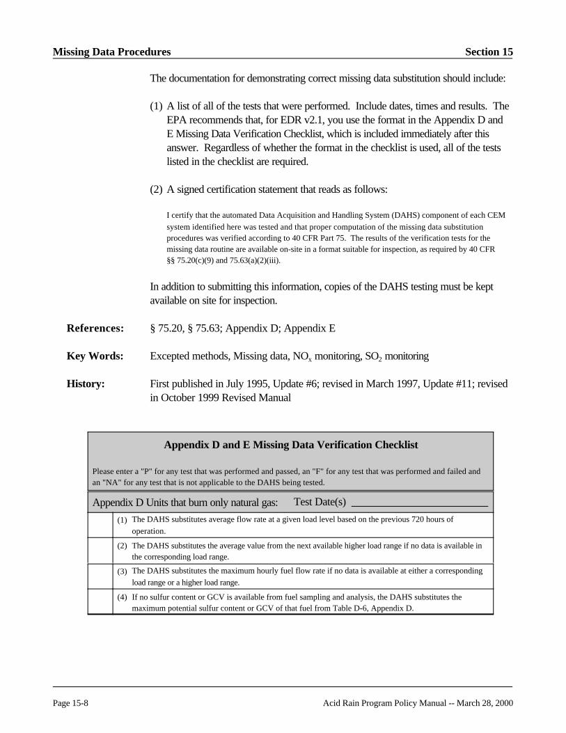
Missing Data Procedures Section 15
Page 15-8 Acid Rain Program Policy Manual -- March 28, 2000
The documentation for demonstrating correct missing data substitution should include:
(1) A list of all of the tests that were performed. Include dates, times and results. TheEPA recommends that, for EDR v2.1, you use the format in the Appendix D andE Missing Data Verification Checklist, which is included immediately after thisanswer. Regardless of whether the format in the checklist is used, all of the testslisted in the checklist are required.
(2) A signed certification statement that reads as follows:
I certify that the automated Data Acquisition and Handling System (DAHS) component of each CEMsystem identified here was tested and that proper computation of the missing data substitutionprocedures was verified according to 40 CFR Part 75. The results of the verification tests for themissing data routine are available on-site in a format suitable for inspection, as required by 40 CFR§§ 75.20(c)(9) and 75.63(a)(2)(iii).
In addition to submitting this information, copies of the DAHS testing must be keptavailable on site for inspection.
References: § 75.20, § 75.63; Appendix D; Appendix E
Key Words: Excepted methods, Missing data, NOx monitoring, SO2 monitoring
History: First published in July 1995, Update #6; revised in March 1997, Update #11; revisedin October 1999 Revised Manual
Appendix D and E Missing Data Verification Checklist
Please enter a "P" for any test that was performed and passed, an "F" for any test that was performed and failed andan "NA" for any test that is not applicable to the DAHS being tested.
Appendix D Units that burn only natural gas: Test Date(s)
(1) The DAHS substitutes average flow rate at a given load level based on the previous 720 hours ofoperation.
(2) The DAHS substitutes the average value from the next available higher load range if no data is available inthe corresponding load range.
(3) The DAHS substitutes the maximum hourly fuel flow rate if no data is available at either a correspondingload range or a higher load range.
(4) If no sulfur content or GCV is available from fuel sampling and analysis, the DAHS substitutes themaximum potential sulfur content or GCV of that fuel from Table D-6, Appendix D.

Section 15 Missing Data Procedures
Acid Rain Program Policy Manual -- March 28, 2000 Page 15-9
Appendix D and E Missing Data Verification Checklist (cont.)
Please enter a "P" for any test that was performed and passed, an "F" for any test that was performed and failed andan "NA" for any test that is not applicable to the DAHS being tested.
Appendix D Units that burn only oil: Test Date(s)
(1) The DAHS substitutes average flow rate at a given load level based on the previous 720 hours ofoperation.
(2) The DAHS substitutes the average value from the next available higher load range if no data is available inthe corresponding load range.
(3) The DAHS substitutes the maximum hourly fuel flow rate if no data is available at either a correspondingload range or a higher load range.
(4) If no sulfur content, GCV or, when necessary, density is available from fuel sampling and analysis theDAHS substitutes the maximum potential sulfur content, GCV, or density of that fuel from Table D-6,Appendix D.
Appendix D Units that can burn both gas and oil: Test Date(s)
(1) If data are available in the corresponding load range:
(a) In an hour when only gas is burned the DAHS substitutes the average fuel flow rate at the correspondingload range from the last 720 hours of gas burning.
(b) In an hour when only oil is burned the DAHS substitutes the average fuel flow rate at the correspondingload range from the last 720 hours of oil burning.
(c) In an hour when both oil and gas are burned but gas fuel flow rate is missing, the DAHS substitutes themaximum fuel flow rate for gas at the corresponding load range from the last 720 hours in which multiplefuels were fired.
(d) In an hour when both oil and gas are burned but oil fuel flow rate is missing, the DAHS substitutes themaximum fuel flow rate for oil at the corresponding load range from the last 720 hours in which multiplefuels were fired.
(2) If data are not available at the corresponding load range but are available at a higher load range:
(a) In an hour when only gas is burned, the DAHS substitutes the average fuel flow rate from the last 720hours of gas burning from the next higher available load range.
(b) In an hour when only oil is burned, the DAHS substitutes the average fuel flow rate from the last 720hours of oil burning from the next higher available load range.
(c) In an hour when both oil and gas are burned, but gas fuel flow rate is missing, the DAHS substitutes themaximum fuel flow rate for gas from the last 720 hours in which multiple fuels were fired from the nexthigher available load range.
(d) In an hour when both oil and gas are burned, but oil fuel flow rate is missing, the DAHS substitutes themaximum fuel flow rate for oil from the last 720 hours in which multiple fuels were fired from the nexthigher available load range.
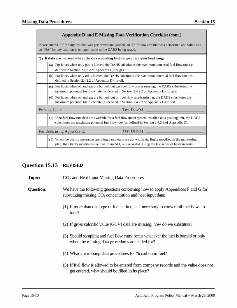
Missing Data Procedures Section 15
Page 15-10 Acid Rain Program Policy Manual -- March 28, 2000
Appendix D and E Missing Data Verification Checklist (cont.)
Please enter a "P" for any test that was performed and passed, an "F" for any test that was performed and failed andan "NA" for any test that is not applicable to the DAHS being tested.
(3) If data are not available at the corresponding load range or a higher load range:
(a) For hours when only gas is burned, the DAHS substitutes the maximum potential fuel flow rate (asdefined in Section 2.4.2.2 of Appendix D) for gas.
(b) For hours when only oil is burned, the DAHS substitutes the maximum potential fuel flow rate (asdefined in Section 2.4.2.2 of Appendix D) for oil.
(c) For hours when oil and gas are burned, but gas fuel flow rate is missing, the DAHS substitutes themaximum potential fuel flow rate (as defined in Section 2.4.2.2 of Appendix D) for gas.
(d) For hours when oil and gas are burned, but oil fuel flow rate is missing, the DAHS substitutes themaximum potential fuel flow rate (as defined in Section 2.4.2.2 of Appendix D) for oil.
Peaking Units: Test Date(s)
(1) If no fuel flow rate data are available for a fuel flow meter system installed on a peaking unit, the DAHSsubstitutes the maximum potential fuel flow rate (as defined in Section 2.4.2.2 of Appendix D).
For Units using Appendix E: Test Date(s)
(1) When the quality assurance operating parameters are not within the limits specified in the monitoringplan, the DAHS substitutes the maximum NOx rate recorded during the last series of baseline tests.
Question 15.13 REVISED
Topic: CO2 and Heat Input Missing Data Procedures
Question: We have the following questions concerning how to apply Appendices F and G forsubstituting missing CO2 concentration and heat input data:
(1) If more than one type of fuel is fired, is it necessary to convert all fuel flows totons?
(2) If gross calorific value (GCV) data are missing, how do we substitute?
(3) Should sampling and fuel flow entry occur whenever the fuel is burned or onlywhen the missing data procedures are called for?
(4) What are missing data procedures for % carbon in fuel?
(5) If fuel flow is allowed to be entered from company records and the value does notget entered, what should be filled in its place?

Section 15 Missing Data Procedures
Acid Rain Program Policy Manual -- March 28, 2000 Page 15-11
(6) If the heat input gap ends mid-week, which weekly fuel flow should be applied, theprevious or the current?
(7) When § 75.35 references Appendix G procedures, does this mean the use ofEquation G-1?
Answer: The provisions in § 75.35(c) which require the use of Appendix G fuel samplingprocedures during periods of missing CO2 data from a CEMS will no longer be ineffect, as of April 1, 2000. The guidance given in paragraphs (1) through (7), below,is therefore to be regarded as interim guidance that will no longer apply after April 1,2000, and do not apply prior to April 1, 2000 if the owner or operator opts to complyearly with § 75.35(d) rather than 75.35(c).
(1) If you are combusting more than one fuel, keep track of the total carbon dioxideemitted for all fuels, as indicated in Equation G-1. Equation G-1 merely calls for atotal mass of carbon from all fuels. You may use any calculation method tocombine information for all fuels that will yield total carbon from all fuels.
(2) If no GCV data are available from fuel sampling and analysis, the DAHSsubstitutes the maximum potential GCV of that fuel from Table D-6, Appendix D.
(3) Fuel carbon content, GCV, and fuel flow information are not required unless thereare CO2 missing data for outages requiring the Appendix G fuel samplingprocedures. However, if the availability during the last unit operating hour duringthe previous calendar quarter was less than 90.0%, or no quality-assured CO2
concentration data are available for a period of 72 consecutive unit operating hoursor more, the utility will need to do sampling and keep track of fuel flow so that theywill be able to substitute any CO2 missing data.
(4) If carbon content values are missing, use carbon content from the most recentsample for the same fuel and the same fuel oil grade or coal rank. If possible, useanother sample from the same supply.
(5) Use the applicable fuel flowmeter missing data procedures in Section 2.4 ofAppendix D.
(6) If the heat input gap ends mid-week, use the fuel flow for that current week.
(7) Yes. Use the procedures under Equation G-1 where § 75.35 calls for AppendixG procedures. (Gas-fired units could also use Equation G-4.)
References: § 75.35; Appendix G

Missing Data Procedures Section 15
Page 15-12 Acid Rain Program Policy Manual -- March 28, 2000
Key Words: Heat input, Missing data
History: First published in November 1995, Update #7; revised in October 1999 RevisedManual
Question 15.14 REVISED
Topic: Appropriate Procedures for Infrequently Operated Units
Question: A unit operates for fewer than 720 hours in a three year period (for example, 700hours of operation from April 1, 1997 to April 1, 2000). Does the utility continue toimplement the standard missing data procedures for SO2 or does the utility insteadimplement the initial missing data procedures?
Answer: Continue to use the standard missing data procedures. Once you have begun using thestandard missing data procedures (i.e., when either: (1) 720 quality-assured monitoroperating hours of SO2, have been recorded since initial certification; or (2) when threeyears have passed since initial certification (whichever occurs first)), the standardmissing data procedures must continue to be used. It makes no difference how manyunit operating hours there are in any subsequent year (or, as in this example, in anythree-year period). The 720-hour historical lookbacks for SO2 missing datasubstitution are based on previously recorded quality-assured monitor operating hours.
References: § 75.31, § 75.32, § 75.33(a)
Key Words: Missing data
History: First published in November 1995, Update #7; revised in October 1999 RevisedManual
Question 15.15 RETIRED

Section 15 Missing Data Procedures
Acid Rain Program Policy Manual -- March 28, 2000 Page 15-13
Question 15.16
Topic: Retraction of ETS User Bulletin #2
Question: Does the Closure Methodology replace the missing data substitution policy in ETSUser Bulletin #2?
Answer: The EPA has retracted ETS User Bulletin #2 and does not consider this official EPApolicy. Some utilities had the incorrect impression that the Agency was intending tosubstitute reported data using the missing data substitution procedures without givingprior notice or an opportunity to resubmit a corrected report. This was never EPA'sintention.
References: N/A
Key Words: Missing data
History: First published in November 1995, Update #7
Question 15.17 REVISED
Topic: Appendix D Missing Data Procedures -- GCV and Density
Question: Which sulfur content value, gross calorific value (GCV), and density value do we usefor a missing oil sample? What do we report?
Answer: Use the maximum potential sulfur content, GCV, or density value for the oil from TableD-6 in Appendix D, to calculate SO2 mass emissions. Report this GCV in column 34of RT 302 and use a missing data flag of "1" in column 44 of RT 302 (if reporting inEDR v1.3) or a data flag of "8" in column 90 of RT 302 (if reporting in EDR v2.1). Report the maximum potential density value for that fuel from Table D-6, Appendix Din column 75 of RT 302 and use a missing data flag of "1" in column 88 of RT 302 (ifreporting in EDR v1.3) or a data flag of "8" in column 92 of RT 302 (if reporting inEDR v2.1).
References: Appendix D, Section 2.4
Key Words: Electronic report formats, Excepted methods, Missing data, SO2 monitoring
History: First published in November 1995, Update #7; revised in October 1999 RevisedManual

Missing Data Procedures Section 15
Page 15-14 Acid Rain Program Policy Manual -- March 28, 2000
Question 15.18 RETIRED
Question 15.19 REVISED
Topic: Appendix E Missing Data Procedures
Question: How do we fill in missing data under Appendix E for the following situations:
! Missing fuel flow rate or gross calorific value data
! NOx emission rate, when excess O2 is outside the original testing limits
! Excess O2
! NOx emission rate, when hourly heat input is higher than the maximum heat inputcorrelated on the curve
! NOx emission rate, when the correlation curve is incomplete?
Also, if data are missing for excess O2 (or other quality assurance/quality controlparameters) for a given hour, is this hour considered "out-of-spec"?
Answer: For missing fuel flow rate and missing gross calorific value data, use the applicablemissing data procedures in Section 2.4 of Appendix D (see Questions 15.9, 15.12,15.17, 15.22, and 15.23).
When excess O2 exceeds by more than 2.0 percentage points O2 the excess O2 valuerecorded at the same operating heat input rate as during the last NOx emission ratetest, substitute the highest tested NOx emission rate on the curve for the fuel. Betweenheat input rate points that were actually tested, make a linear interpolation of theexcess O2. In RT 323 (if used), report a flag value of "N" in column 21 to show thatthe excess O2 is outside of the specified value. If RT 324 is used, report the "N" flagin column 24. Below the lowest heat input rate point do not keep track of the excessO2.
For missing or invalid excess O2 data, substitute the highest NOx emission rate on thecurve for the fuel. However, in RT 323 (if used), report a flag value of "X" in column21. If RT 324 is used, report the "X" flag in column 24. This indicates that the hour isnot demonstrated to be within the specified limits in section 2.3 of Appendix E, but italso is not demonstrated to be outside the specified limits. Use of the "X" flag isoptional; you may choose instead to treat these hours as out of specification. Note
Section 15 Missing Data Procedures
Acid Rain Program Policy Manual -- March 28, 2000 Page 15-15
that hours marked with a flag of "N" count towards the 16 consecutive unit operatinghours before retesting is required, while hours marked with a flag of "X" do not countfor this purpose. However, in either case, the data count against the availability of datawhere the unit operates within the parameters. If the data availability falls below 90.0percent, the Agency may require retesting.
Note that the same procedures apply when a quality assurance/quality controlparameter other than excess O2 is missing (e.g., steam/fuel injection ratio, compressorratio).
If the hourly heat input is higher then the maximum heat input correlated on the curve,then calculate the maximum potential NOx emission rate and calculate the NOx
emission rate that would result from extrapolating the last two heat input points on thecorrelation curve. Substitute the higher of these two values. During your next periodicor quality assurance/quality control related testing, try to test under conditions morerepresentative of your maximum potential heat rate. If possible, use the new maximumheat input as the highest heat input point. Flag these data in RT 323 (if used) with a"W" in column 21 or, if applicable, with a "W" in column 24 of RT 324 (see EDR v2.1Reporting Instructions).
If the NOx versus heat input curve is not complete, then use the maximum potentialNOx emission rate and complete your testing as soon as possible. Calculate themaximum potential NOx emission rate (MER) using the applicable equation fromAppendix F to Part 75 or from EPA Method 19. In calculating the MER, use themaximum potential concentration of NOx, and the minimum carbon dioxideconcentration or maximum oxygen concentration under typical operating conditions(based on historical information). Alternatively, you may use the appropriate diluentcap value in the calculations (i.e., 5.0% CO2 or 14.0% O2 for boilers, or 1.0% CO2
or 19.0% O2 for turbines), as specified in Section 2.1.2.1 of Appendix A.
References: Appendix D, Section 2.4; Appendix E, Sections 2.3 and 2.5
Key Words: Excepted methods, Missing data, NOx monitoring
History: First published in November 1995, Update #7; revised in October 1999 RevisedManual

Missing Data Procedures Section 15
Page 15-16 Acid Rain Program Policy Manual -- March 28, 2000
Question 15.20
Topic: Missing Load Data
Question: For the new fuel flow missing data procedures, what should we do if MW is missingfor an hour of missing fuel flow? Can we use maximum value substitution of fuel flow? If MW is missing for an hour of valid flow, should the quality assured flow rate beentered into the lowest load range?
Answer: If MW data are available but are not in the DAHS, these data must be entered into theDAHS manually. If the MW data are not available, you must use the unit’s maximumload. In this case treat the load ranges for fuel flow missing data as you would the loadranges for NOx and flow stack monitors. If MW are missing for an hour of missingfuel flow, substitute values from the highest load range. If MW data are missing for anhour of valid flow, enter the flow rate in the lowest load range.
References: Appendix D, Section 2.4.2
Key Words: Excepted methods, Fuel sampling, Missing data
History: First published in November 1995, Update #7
Question 15.21
Topic: Appendix D Missing Data Procedures
Question: The new missing data procedures for fuel flow during combustion of multiple fuelsrequire substitution of the maximum flow rate in a load range, rather than the average. Why is the approach different for multiple fuels?
Answer: The approach is different for multiple fuels in order to avoid underestimation of SO2
mass emissions. When a unit combusts two different fuels simultaneously, each with itsown fuel flow meter, there is not a direct relationship between the flow rate of a singlefuel and the unit load. It would be possible to underestimate SO2 emissionssignificantly if a low oil flow value from an hour with combustion of a little oil andmostly natural gas were substituted for the oil flow rate during an hour when the unitactually combusted mostly oil and a little natural gas. However, substituting themaximum value in the load range during periods of co-firing ensure that the flow rateand SO2 mass emissions will not be underestimated.
References: Appendix D, Section 2.4.2.3

Section 15 Missing Data Procedures
Acid Rain Program Policy Manual -- March 28, 2000 Page 15-17
Key Words: Excepted methods, Fuel sampling, Missing data
History: First published in November 1995, Update #7
Question 15.22 REVISED
Topic: Appendix D Missing Data Procedures
Question: Are there any initial missing data procedures in Appendix D for fuel flowmeter data?
Answer: No. Beginning with the hour of provisional certification, use the standard missing dataprocedures in Section 2.4 of Appendix D. If there are fewer than 720 hours ofhistorical quality-assured fuel flow data available for a look back during a missing dataperiod, use whatever quality-assured hours are available, consistent with Section2.4.2.2 of Appendix D. See also the answer to Question 15.12.
References: Appendix D, Section 2.4
Key Words: Excepted methods, Fuel sampling, Missing data
History: First published in November 1995, Update #7; revised in October 1999 RevisedManual
Question 15.23 REVISED
Topic: Appendix D Missing Data Procedures
Question: In the missing data procedures for fuel flowmeters in Appendix D, does the 720-hourlook back period include only hours in which a quality-assured fuel flow rate wasrecorded?
Answer: Yes. Do not include in the lookback period any hours when no fuel was combusted orany hours when the fuel flowmeter was either malfunctioning or not operating. If thereare fewer than 720 hours of historical quality-assured fuel flow data for a particular fuelduring a missing data period, use whatever quality-assured hours are available,consistent with Section 2.4.2.2 of Appendix D.
References: Appendix D, Section 2.4

Missing Data Procedures Section 15
Page 15-18 Acid Rain Program Policy Manual -- March 28, 2000
Key Words: Excepted methods, Fuel sampling, Missing data
History: First published in November 1995, Update #7; revised in October 1999 RevisedManual
Question 15.24 REVISED
Topic: Valid Hour -- Calibration Error Tests
Question: If a successful daily calibration error test of a CEMS ended at 08:16 and the unitcompletes shutdown at 08:29 with at least one minute of valid data, are there sufficientdata for a valid hour?
Answer: No. During periods when calibration, quality assurance, or maintenance activitiespursuant to § 75.21 and Appendix B are being performed, a valid hour shall consist ofat least two data points separated by a minimum of 15 minutes.
References: § 75.10, § 75.21; Appendix B
Key Words: Data validity, Missing data
History: First published in November 1995, Update #7; revised in October 1999 RevisedManual
Question 15.25 RETIRED
Question 15.26 REVISED
Topic: Missed QA/QC Tests -- Linearity Checks and RATAs
Question: A utility did not perform a required linearity test or RATA in a quarter. Must the utilityimmediately begin to report using substitute data in the next quarter?
Answer: No, EPA recognizes that there are times that a linearity check or RATA deadline maybe missed due to circumstances beyond a utility's control. Therefore, the revisions toPart 75 published on May 26, 1999 provide a grace period in which a missed QA testmay be completed without loss of data. Section 2.2.4 of Appendix B provides a 168

Section 15 Missing Data Procedures
Acid Rain Program Policy Manual -- March 28, 2000 Page 15-19
unit (or stack) operating hour grace period for a missed linearity check and Section2.3.3 of Appendix B provides a 720 unit (or stack) operating hour grace period for amissed RATA. If the required QA test has not been successfully completed within thegrace period, data from the monitoring system become invalid beginning with the firstoperating hour after the grace period expires.
References: Appendix B, Sections 2.2.4 and 2.3.3
Key Words: Deadlines, Linearity, Missing data, RATA
History: First published in March 1997, Update #11; revised in October 1999 Revised Manual
Question 15.27 RETIRED
Question 15.28
Topic: Diluent Monitor Data Availability
Question: For CO2 and heat input missing data, when do I start reporting diluent monitor dataavailability on an hourly basis -- with the hour I do the EDR v2.1 upgrade?
Answer: This is covered in §§ 75.35 and 75.36. In the case where an existing, certified diluentmonitor is in place, when you implement the new missing data algorithms for CO2 orO2 (as applicable) you must perform the initial missing data procedures of § 75.31(b)for the first 720 quality assured monitor operating hours, and then switch to thestandard missing data procedures in § 75.35(d) or § 75.36(d), as applicable. Monitordata availability calculation and reporting begins when you begin using the standardmissing data procedures.
The new CO2 and heat input missing data algorithms may be implemented beginning onJanuary 1, 2000 and must be implemented no later than April 1, 2000. The firstoperating hour of the quarter in which you first report data in EDR v2.1 is the properpoint at which to start using the initial missing data procedures of § 75.31(b). Notethat you may upgrade to EDR v2.1 only at the beginning of a calendar quarter, not inthe middle of a quarter.
References: § 75.35, § 75.36

Missing Data Procedures Section 15
Page 15-20 Acid Rain Program Policy Manual -- March 28, 2000
Key Words: Diluent monitors, Missing data
History: First published in March 2000, Update #12
Question 15.29
Topic: Missing Data Procedures After EDR Upgrade
Question: When I upgrade to EDR v2.1, should I reset the missing data clock and the percentmonitor data availability (PMA) and begin using the initial missing data procedures in§ 75.31?
Answer: It depends on the parameter. Use the initial missing data procedures of § 75.31 onlyfor parameters such as CO2 and moisture, for which hourly reporting of PMA was notrequired in the past, but now is required under the May 26, 1999 revisions to Part 75. However, for SO2, NOx, and flow rate, maintain the connection with the historical datastreams when you switch to EDR v2.1 (i.e., do not reset the missing data lookbackperiod or the PMA).
References: § 75.31
Key Words: Missing data
History: First published in March 2000, Update #12
Question 15.30
Topic: Valid Hours
Question: Suppose that in the first two 15-minute quadrants of an hour (Hour # 1), I collectsufficient valid CEMS data to meet the requirement of § 75.10(d)(1) and then Iperform preventative maintenance on the CEMS for the remainder of that hour,extending into the next clock hour (Hour # 2). If the monitor passes a post-maintenance calibration error test in Hour # 2 and collects sufficient valid data in thelast two 15 minute quadrants of Hour # 2 to satisfy § 75.10(d)(1), are both Hours # 1and 2 valid, or is only Hour # 2 valid ?
Answer: The emission data for both Hours # 1 and # 2 may be reported as quality-assured. The principal data capture requirement for Part 75 sources in § 75.10(d)(1) states that

Section 15 Missing Data Procedures
Acid Rain Program Policy Manual -- March 28, 2000 Page 15-21
in order to validate data for an hour, you must obtain at least one valid data point ineach quadrant of the hour in which fuel is combusted. However, § 75.10(d)(1)provides an exception to this requirement for hours in which quality assurance testingand preventive maintenance activities are performed. For such hours, a minimum oftwo data points, separated by at least 15 minutes, are required to validate the hour.
In the present case, the emission data collected in Hour # 1 are considered valid,because the data were recorded prior to the maintenance event (i.e., prior tocommencement of the out-of-control period). The data in Hour # 2 are valid becausethey were collected after a successful post-maintenance calibration error test (i.e., afterthe end of the out-of-control period).
References: § 75.10(d)(1)
Key Words: Data validity
History: First published in March 2000, Update #12

Subtractive Configurations Section 22
Page 15-22 Acid Rain Program Policy Manual -- March 28, 2000
[This page intentionally left blank.]

Acid Rain Program Policy Manual -- March 28, 2000 Page 16-i
SECTION 16SCRUBBERS/PARAMETRIC MONITORING
PROCEDURES
Page
16.1 REVISED Missing Data -- Scrubbed Units . . . . . . . . . . . . . . . . . . . . . . . . . 16-1
16.1A RETIRED
16.2 Missing Data -- Scrubbed Units . . . . . . . . . . . . . . . . . . . . . . . . . . . . . . . . . . . 16-3
16.3 REVISED Control Device Operation during a Missing Data Period . . . . . . . 16-4
16.4 Scrubber Modules -- Slurry Flow Measurement . . . . . . . . . . . . . . . . . . . . . . . 16-5
16.5 RETIRED
16.6 RETIRED
16.7 RETIRED
16.8 RETIRED
16.9 RETIRED
16.10 REVISED Scrubber Installation -- Interim Reporting . . . . . . . . . . . . . . . . . . 16-6
16.11 RETIRED
16.12 RETIRED
16.13 RETIRED

Scrubbers and Parametric Monitoring Procedures Section 16
Page 16-ii Acid Rain Program Policy Manual -- March 28, 2000
[This page intentionally left blank]

Section 16 Scrubbers and Parametric Monitoring Procedures
Acid Rain Program Policy Manual -- March 28, 2000 Page 16-1
Question 16.1 REVISED
Topic: Missing Data -- Scrubbed Units
Question: Are the parametric monitoring procedures, used for recording and reporting duringmissing data periods, optional for scrubbed units?
Answer: Yes. The parametric monitoring procedures referenced in § 75.34(a)(2), (b), and (c) and described in detail in 40 CFR Part 75, Appendix C areoptional. The owner or operator of a unit with add-on control devices has thefollowing options with respect to parameter monitoring and calculating missing data.
(1) Standard Missing Data Routines with Parametric Supporting Data
The owner or operator may use the standard missing data routines in § 75.33 providedthat the parameters specified in § 75.55(b) or § 75.58(b) (or similar parametersappropriate to the particular site for demonstrating proper emissions control) arerecorded and maintained on-site, and provided that the parameter data documentproper operation of the control device during the missing data period. The owner oroperator does not need to report this information to EPA unless EPA requests thedata. The owner or operator also does not need to use a DAHS to record theparameters. This is because the parameter data are not used to calculate the missingdata, but are only used to document that the control system is operating properly. Ifthe monitor data availability for the affected unit falls below 90%, then the owner oroperator also may submit a petition as described under Option (4) below.
In order to demonstrate proper operation, the utility must determine the range of eachappropriate scrubber operating parameter that corresponds to proper operation, thedesignated representative must submit a list of the range of these parameters as anupdate to the monitoring plan with the quarterly report for fourth quarter 1995, and theutility must keep records to show whether the scrubber is operating inside or outside ofthose ranges. In quarterly reports beginning with the report for fourth quarter 1995,the designated representative must certify that the add-on emission controls wereoperating within the range of parameters listed in the monitoring plan, and that thesubstitute values recorded during the quarter do not systematically underestimate SO2
or NOx emissions, pursuant to § 75.34.
(2) No Parameter Data
Pursuant to § 75.34(d), if the owner or operator does not have data available todemonstrate that an add-on control device is operating properly (i.e., the dataspecified in § 75.55(b) or § 75.58(b)), the owner or operator must, as applicable: (a)use the maximum potential NOx emission rate; or (b) use the maximum hourly SO2

Scrubbers and Parametric Monitoring Procedures Section 16
Page 16-2 Acid Rain Program Policy Manual -- March 28, 2000
concentration recorded by the inlet monitor for the previous 720 operating hours incalculating SO2 emissions. If no inlet SO2 monitor concentration data exist, then theowner or operator must use the maximum potential inlet SO2 concentration establishedpursuant to Section 2.1.1.1 of Appendix A to Part 75. These maximum SO2 or NOx
values, as applicable, must be used to substitute for missing data until parametric datademonstrating proper operation of the SO2 or NOx controls are available. Note thatthese values may be higher than the maximum recorded value used to substitute valuesunder the standard missing data procedures in § 75.33 when monitor data availabilityis < 90%.
(3) Parametric Missing Data Substitution Method
The owner or operator can petition EPA to use parametric monitoring to calculatesubstitute values during missing data periods. This option is referenced in§ 75.34(a)(2), (b), and (c), and described in detail in Appendix C and § 75.66(e). The petition should be submitted prior to implementing a parametric substitutionapproach and must include the demonstration requirements in Appendix C. Once thepetition is approved by EPA, the owner or operator must use an automated dataacquisition and handling system to record and report the parameters specified in§ 75.55(b) or 75.58(b) (and any other parameters approved during the petitionprocess) for use in determining the substitute values used to fill in for missing CEMdata. These parameters then must be recorded continuously and reported duringmissing data periods in the Electronic Reporting Format specified by the Administrator,as required under § 75.64.
If the monitor data availability for the affected unit falls below 90%, then the owner oroperator must use either the standard missing data routines under Option (1) above orsubmit a separate petition as described in Option (4) below. If parameter data are notavailable to demonstrate that the control device is operating properly, then the owneror operator must use Option (2) above to calculate substitute values on the basis ofmaximum potential concentration or maximum potential NOx emission rate.
(4) Parameter Data Used to Support Use of Maximum Controlled EmissionRate
When monitor data availability is < 90% the standard missing data procedures requirethe owner or operator to use the "maximum recorded value" in the lookback period(720 operating hours for SO2 and 2160 operating hours for NOx) as the substitutevalue for missing data. Because that value may include periods when a control devicewas not operating, § 75.34(a)(1) gives the owner or operator the option to petitionEPA to use instead the "maximum controlled emission rate" during the previous 720operating hour period as the substitute value for missing SO2 or NOx data, provided

Section 16 Scrubbers and Parametric Monitoring Procedures
Acid Rain Program Policy Manual -- March 28, 2000 Page 16-3
that parameter data documenting proper operation of the control device are availableduring the missing data period.
The required petition to EPA could be included as part of the quarterly report. Thedesignated representative would be required to provide the following informationpursuant to § 75.66(f): (a) data availability for the missing data period was < 90%; (b) parametric monitoring records (specifically, the records identified by § 75.55(b) or§ 75.58(b)) demonstrating proper control device operation (within the range ofoperating parameters in the monitoring plan for the unit) are available on site; (c) a listof average hourly values for the last 720 operating hours, highlighting the maximumrecorded value and the maximum controlled emission rate value; and (d) anexplanation and information on operation of the add-on emission controlsdemonstrating that the selected historical SO2 concentration or NOx emission ratedoes not underestimate emissions during the missing data period. The petition mustinclude a certified statement that items (a) and (b) are true, accurate, and complete. The actual parametric records for every hour need not be submitted, in contrast to thereporting requirements under Option (3) above where the recorded parameters areused to calculate the substitute values.
References: §75.33, § 75.34, § 75.55(b), § 75.58(b), § 75.64(c), § 75.66(e), § 75.66(f);Appendix C
Key Words: Control devices, Missing data
History: First published in May 1993, Update #1; revised July 1995, Update #6; revised inOctober 1999 Revised Manual
Question 16.1A RETIRED
Question 16.2
Topic: Missing Data -- Scrubbed Units
Question: Do all parameters for all scrubber modules need to be obtained in order for sources todemonstrate that a scrubber is working sufficiently for the regular missing dataprocedures to apply?
Answer: No, but there must be a sufficiently large amount of data to demonstrate that the FGDsystem is working at, or close to, its regular efficiency. As a guideline, EPA strongly
Scrubbers and Parametric Monitoring Procedures Section 16
Page 16-4 Acid Rain Program Policy Manual -- March 28, 2000
recommends at least 90% of the data required be available during monitor outages. Without this data, the provisions of § 75.34(d) apply. (See option (2) in Question16.1 for a discussion of § 75.34(d).)
References: § 75.34(a)(1)
Key Words: Control devices, Missing data
History: First published in May 1993, Update #1
Question 16.3 REVISED
Topic: Control Device Operation during a Missing Data Period
Question: Section 75.34(d) states that "the owner or operator shall keep records of informationas described in subpart F of this part to verify the proper operation of the SO2 or NOx
emission controls during all periods of SO2 or NOx emission missing data." If datasubstitution is being completed in accordance with § 75.34(a)(1), what specificscrubber operating information must be recorded? Also, please indicate the specificsections of subpart F which provide this information.
Answer: The specific recordkeeping procedures for the proper operation of the SO2 and NOx
emissions controls can be found in § 75.55(b)(3) and § 75.58(b)(3). The informationmust be recorded but need not be reported to the Agency with the quarterly report. This recorded information must be kept at the site for 3 years. This information mustbe available on demand in the event of a field audit or a request by the Agency. Theinformation to verify the proper operation of an emission control device can berecorded by strip chart or by electronic media (i.e., by computer).
References: § 75.34(d), § 75.55(b)(3), § 75.58(b)(3), § 75.64(a)(2)(iv)
Key Words: Control devices, Missing data, Recordkeeping
History: First published in November 1993, Update #2; revised July 1995, Update #6; revisedin October 1999 Revised Manual
Section 16 Scrubbers and Parametric Monitoring Procedures
Acid Rain Program Policy Manual -- March 28, 2000 Page 16-5
Question 16.4
Topic: Scrubber Modules -- Slurry Flow Measurement
Question: For an FGD with several modules, can verification and reporting of the number ofpumps operating on each module and the tested flow rate of the pump be used tocalculate the flow rate to meet the flow measurement requirement?
Answer: Yes, the verification of flow of slurry through the pipes can be performed by reportingthe number of pumps operating on each module and the tested flow rate of each pumpin operation, provided that the pumps are all fixed-rate. If the pumps operate atvariable rates, then there must be flowmeters for each scrubber module.
References: § 75.34; Appendix C, Section 1.2
Key Words: Control devices, Parametric procedures
History: First published in November 1993, Update #2
Question 16.5 RETIRED
Question 16.6 RETIRED
Question 16.7 RETIRED
Question 16.8 RETIRED
Question 16.9 RETIRED

Scrubbers and Parametric Monitoring Procedures Section 16
Page 16-6 Acid Rain Program Policy Manual -- March 28, 2000
Question 16.10 REVISED
Topic: Scrubber Installation -- Interim Reporting
Question: When SO2 scrubbers are installed on Part 75 affected units, this often involvesconstruction of a new stack and installation of new continuous emission monitoringsystems. Consequently, there will, in most instances, be a period of time after thescrubber comes on-line during which the unit will emit SO2, NOx, and CO2 into theatmosphere without having certified monitors to measure the emissions. Must themaximum potential concentration and velocity values be used for reporting during thistime interval? If not, how should emission data be reported from a scrubbed unit in theinterval prior to certification of the continuous emission monitors?
Answer: In most instances, it is not necessary to use maximum potential concentration and flowrate values. Rather, in the time interval that extends from the initial hour of unitoperation following scrubber installation until the hour of successful completion of thecertification tests of the continuous monitoring systems, follow the interim reportingguidelines given in Sections I and II, below.
INTERIM REPORTING GUIDELINES FOR SCRUBBED UNITS
The interim reporting guidelines in Sections I and II, below apply only to situations inwhich: (1) a flue gas desulfurization (FGD) system is installed on a Part 75 affectedunit (or units); and (2) both the normal operation of the affected unit(s) and the abilityof the continuous emission monitoring systems to provide quality-assured SO2
emissions data for Part 75 reporting purposes are disrupted by the installation of theFGD system. Further, the guidelines apply only for a limited time period, not toexceed 90 calendar days, beginning with the first hour of operation of the unit(s) afterinstallation of the FGD system (see § 75.4(e)), and extending to the hour of completionof the CEM certification tests. These guidelines are not to be used under any othercircumstances.
I. CERTIFICATION TEST SEQUENCE:
A. In cases where scrubber installation involves extensive modification of the flue gashandling system and construction of a new stack and requires the installation ofnew (or relocated) continuous emission monitoring systems, the recommendedsequence of CEM certification tests is as follows:
(1) Install all CEM systems prior to initial scrubber operation. Prepare themonitors for use in accordance with the manufacturer's instructions.

Section 16 Scrubbers and Parametric Monitoring Procedures
Acid Rain Program Policy Manual -- March 28, 2000 Page 16-7
(2) Update the monitoring plan to reflect the changes to the process and/ormonitoring systems. Assign new component and system ID numbers in RT510 of the monitoring plan to all new and relocated monitoring systems. TheDAHS component ID number need not be changed, however, if the sameDAHS and the same software are used before and after scrubberinstallation.
(3) For the gas monitoring systems, initiate a calibration error test as soon aspossible after the scrubbed unit first comes on-line. The unit must be inoperation during the test, although no particular load or scrubber efficiency isrequired. Check the calibration of both the low and high ranges of the SO2
monitor.
Until the monitor has passed a calibration error test, no data generated by agas monitor will be accepted, and missing data routines as stated in § 75.31must be applied.
(4) For each gas monitor, once a calibration error test has been passed,continue performing daily calibration error tests of the monitor on eachsubsequent unit operating day.
(5) For each installed flow monitor, any necessary characterization orlinearization of the instrument with respect to EPA Method 2 (or itsallowable alternatives) should be done as soon as possible after initialoperation of the scrubbed unit. Until the pre-RATA adjustments of themonitor have been completed, no data from a flow monitor will be accepted,and missing data routines must be applied. Therefore, for missing datapurposes, it is advisable to collect Reference Method 2 data while thelinearization or other pre-RATA adjustments are in progress, in order to fillone or more load ranges (see Section II.C, below).
Hourly Method 2 data must be collected in accordance with the proceduresoutlined in Question 21.37.
(6) When linearization of the flow monitor is completed (or, if no pre-RATAadjustment procedures are considered necessary), initiate a calibration errortest and interference check of the monitor, and repeat the tests on eachsubsequent operating day.
(7) After all set up, adjustment, linearization, etc. of a monitor is completed anda calibration error test has been passed, you may either: (a) invalidate alldata from the monitor until all of the required certification tests have beenpassed; or (b) apply the data validation procedures and timelines of

Scrubbers and Parametric Monitoring Procedures Section 16
Page 16-8 Acid Rain Program Policy Manual -- March 28, 2000
§ 75.20(b)(3) to conditionally validate data from the monitor until thecertification tests have been passed. If you select option (b), use the firstsuccessful calibration error test performed after the instrument set-up as theprobationary calibration error test described under § 75.20(b)(3)(ii).
(8) It is recommended that the linearity checks, cycle/response time tests and the7-day calibration error tests of the monitors be initiated first. Performlinearity checks on both the low and high SO2 monitor ranges. The unitneeds only to be operating (no particular load-level or scrubber efficiency isrequired) during these tests.
(9) It is recommended that RATA testing of the SO2, NOx, flow rate, and CO2
monitoring systems be done last in the test sequence, commencing as soonas stable unit and scrubber operation at normal load is attained.
(10) To facilitate data validation and reporting, initiate and complete the entirecertification test sequence within the same calendar quarter, if at all possible.
(11) The certification tests of all monitoring systems must be completed no laterthan 90 days after effluent gases from the scrubber stack are first dischargedto the atmosphere.
B. In cases where scrubber installation does not involve construction of a new stackor the installation of new (or relocated) continuous monitoring systems, proceed asfollows:
(1) Conduct a 12-point stratification check of the scrubber effluent stream, atthe CEM or reference method sampling location, in accordance with Section6.5.6.1 of Appendix A to Part 75.
(2) No additional certification tests are required for the high-scale SO2 monitor,provided that the high-scale has been previously certified in accordance withPart 75 requirements.
(3) No additional certification tests are required for the NOx monitoring systemor for the CO2 pollutant monitor, provided that: (1) these monitors havebeen previously certified in accordance with Part 75 requirements; (2) the results of the stratification check indicate that stratification is absent(using the criteria in Section 6.5.6.3(a) of Appendix A); and (3) if thesemonitoring systems are dilution extractive-type systems, the size of thecritical orifice is not changed. If stratification is found to be present or thesize of the critical orifice is changed, however, a normal-load RATA of thesemonitoring systems is required.

Section 16 Scrubbers and Parametric Monitoring Procedures
Acid Rain Program Policy Manual -- March 28, 2000 Page 16-9
(4) If the low and high scales of the SO2 monitor are on the same analyzer anddiffer only by a gain factor, a linearity check and 7-day calibration error testare the only tests required for the low-scale unless the results of thestratification test show stratification to be present or, if applicable, the size ofthe critical orifice is changed. If stratification is present or if the size of thecritical orifice is changed, a low-scale RATA at normal load is also required.
If the low-scale SO2 monitor is a different analyzer from the high-scale SO2
monitor, all four certification tests (i.e., a linearity test, a 7-day calibrationerror test, a normal-load RATA, and a cycle/response time test) arerequired, irrespective of the results of the stratification test and whether ornot the size of the critical orifice is changed.
(5) Update the monitoring plan to reflect the changes made to the SO2
monitoring system. If the SO2 low and high scales are on the same analyzer,you may either represent them as two components of the same system in RT510 of the electronic monitoring plan or you may represent them as a singlecomponent, with a “component type code” of “SO2A” in RT 510, column23. If the low and high scales are two different analyzers, show them asseparate monitoring systems.
(6) Recertification of the flow monitor (i.e., a 3-load RATA) is required.
II. DATA REPORTING:
A. All conditionally valid data generated by the primary Part 75 monitoring systems inthe time interval (not to exceed 90 days) between the first hour of scrubberoperation until the hour of completion of the CEM certification tests may be usedfor Part 75 reporting purposes, provided that the data validation requirements of§ 75.20(b)(3) are met. Any data recorded by reference methods may also beused for reporting purposes.
B. Apply the appropriate bias adjustment factors to the CEMS data used forreporting (SO2, NOx, and flow rate, only), in accordance with the results of theRATA tests. Use a BAF of 1.000 until the hour of completion of the RATA. If aCEMS fails the bias test, calculate the BAF and apply it to the subsequent datafrom the CEMS, beginning with the hour after completion of the RATA (seeSection 7.6.5 of Appendix A to Part 75).
C. Prior to provisional certification of a CEMS, for any hours in which no ReferenceMethod data are available for reporting, provide substitute data for NOx, flowrate, and CO2, using Option 1, 2, or 3, below. For SO2, Option 3 may be usedwithout qualification; however, Option 1 or 2 may only be used if it can be
Scrubbers and Parametric Monitoring Procedures Section 16
Page 16-10 Acid Rain Program Policy Manual -- March 28, 2000
demonstrated that the scrubber was working properly during the missing dataperiod. This can be demonstrated by submitting to EPA all of the hourlyinformation required by § 75.55(b)(1) or § 75.58(b)(1) along with the quarterlyreport. As part of the submittal to EPA, identify, for each parameter in§ 75.55(b)(1) or § 75.58(b)(1), the range of acceptable values that indicatesproper scrubber operation. The required hourly information must be provided foreach hour of each missing data period in the interval from the initial hour ofscrubber operation until the SO2 monitor is provisionally certified. Report anMODC of 05 for any hours in which parametric data are used to determinemissing data. If, for any hour of missing data, the scrubber is not workingproperly or the parametric data are not provided to EPA, SO2 missing data mustbe substituted using Option 3.
(1) Maintain the connection to the historical (unscrubbed) data stream. In orderto use this option, the unit-stack configuration must remain the same. Forexample, this option may be used if, both before and after installation of thescrubber, a unit emits through one stack. It may not be used, however, iftwo unscrubbed units which had previously emitted through separate stacksare connected to a common scrubber and now emit through one stack. Depending upon how many hours of historical quality-assured data werecollected prior to installation of the scrubber, apply whichever missing dataprocedures were in effect at the time of scrubber installation (i.e., either§ 75.31, § 75.33, or § 75.34).
(2) Re-start the initial missing data procedures of § 75.31, beginning with thefirst hour of operation of the scrubbed unit. If this option is selected,reference method data collected prior to a missing data period may be usedto provide quality-assured data for the missing data routines. For NOx andflow rate, the reference method data in a particular load range may be usedto provide substitute data for that load range or for any lower load range.
(3) Report using the maximum potential concentrations and/or flowrates and/oremission rates.
D. For hours in which some or all of the effluent from the affected unit(s) is diverted toa bypass stack, the emissions must either be measured by certified Part 75monitoring systems, or the maximum potential values for SO2 concentration, CO2
pollutant concentration and total volumetric flowrate must be reported. For NOx,report the maximum potential NOx emission rate in lb/mmBtu.
E. Include in RT 910 of the electronic quarterly report (or in the cover letter thataccompanies the quarterly report) the following information:
Section 16 Scrubbers and Parametric Monitoring Procedures
Acid Rain Program Policy Manual -- March 28, 2000 Page 16-11
(1) The date and clock hour when the scrubbed unit(s) first operated;
(2) The dates and times of the certification tests of each of the monitoringsystems used for "interim" data reporting (i.e., in the interval from initialscrubber operation until successful completion of the CEM certificationtests);
(3) For each monitoring system used for interim data reporting, include the dateand hour in which quality-assured data were first used for reporting (this dateand time is considered to be the date and time of provisional certification forthe monitoring system); and
(4) An explanation of the missing data procedures used for SO2, NOx, flowrate, and CO2 in the interval between initial scrubbed unit operation andcertification of the continuous monitoring systems.
F. Report the results of all daily calibrations used to validate the monitoring data usedfor interim data reporting, in RT 230.
G. Use the EDR Method of Determination Codes in Table 4A under § 75.57, in theusual manner.
H. At the end of the interim period (i.e., when either: (1) the certification tests of themonitoring systems have been completed; or (2) 90 days have elapsed since initialoperation of the scrubbed unit), return to the normal Part 75 data validation andreporting procedures.
References: § 75.4(e), § 75.20(b)(3), § 75.31, § 75.33, § 75.57, § 75.66
Key Words: Certification tests, Control devices, Missing data, Reporting
History: First published in July 1995, Update #6; revised in October 1999 Revised Manual
Question 16.11 RETIRED

Scrubbers and Parametric Monitoring Procedures Section 16
Page 16-12 Acid Rain Program Policy Manual -- March 28, 2000
Question 16.12 RETIRED
Question 16.13 RETIRED

Acid Rain Program Policy Manual -- March 28, 2000 Page 17-i
SECTION 17COMMON, MULTIPLE, AND COMPLEX
STACKS
Page
17.1 REVISED Common Stack RATAs . . . . . . . . . . . . . . . . . . . . . . . . . . . . . . . 17-1
17.2 REVISED Monitor Location . . . . . . . . . . . . . . . . . . . . . . . . . . . . . . . . . . . . 17-1
17.3 Load Ranges . . . . . . . . . . . . . . . . . . . . . . . . . . . . . . . . . . . . . . . . . . . . . . . . . 17-2
17.4 RETIRED
17.5 REVISED Common Stack -- Heat Input Rate Apportionment . . . . . . . . . . . 17-3
17.6 REVISED NOx Emission Rate Monitoring Systems and Reporting . . . . . . . . 17-3
17.7 REVISED NOx Emission Rate Monitoring in All Stacks or Ducts . . . . . . . . . 17-4
17.8 Definition of Boiler Emission Controls for NOx Monitoring in Multiple Stacks or Ducts . . . . . . . . . . . . . . . . . . . . . . . . . . . . . . . . . . . . . . . . . . . . . . . 17-5
17.9 REVISED SO2 Monitoring in Multiple Stacks or Ducts . . . . . . . . . . . . . . . . 17-5
17.10 REVISED CO2 Monitoring and Reporting for Multiple Stacks or Ducts . . . . 17-6
17.11 REVISED Heat Input Calculations and Reporting for Monitoring in Multiple Stacks or Ducts . . . . . . . . . . . . . . . . . . . . . . . . . . . . . . 17-7
17.12 REVISED Operating Data for Monitoring in Multiple Stacks or Ducts . . . . . 17-8
17.13 REVISED Multiple Stacks -- NOx Emission Rate Calculations . . . . . . . . . . 17-8
17.14 REVISED Reporting Partial Operating Hours for Multiple Stack Units . . . . . 17-9

Common, Multiple, and Complex Stacks Section 17
Page 17-ii Acid Rain Program Policy Manual -- March 28, 2000
[This page intentionally left blank]

Section 17 Common, Multiple, and Complex Stacks
Acid Rain Program Policy Manual -- March 28, 2000 Page 17-1
Question 17.1 REVISED
Topic: Common Stack RATAs
Question: For a multi-unit situation where more than one unit feeds a common stack, how doesEPA define low, medium, and high load for RATA purposes since there are numerouspermutations or combinations in flows to the stack?
Answer: The method for determining the range of operation and the low, mid and high loadlevels for a unit or common stack is found in Section 6.5.2.1 of Appendix A to Part75. For a common stack, the lower boundary of the range of operation is either: (1)the lowest minimum, safe stable load for any of the units discharging through thecommon stack; or (2) for a group of frequently-operated units, the sum of the minimumsafe, stable loads of the individual units. The upper boundary of the range of operationis defined as the sum of the maximum sustainable loads for the individual units, unlessthat combined load is unattainable in practice, in which case, use the maximumsustainable combined load from a four quarter (minimum) historical lookback. Thelow, mid, and high load levels are expressed as percentages of the range of operation(0 - 30% of range = low, 30 - 60% = mid, and 60 - 100% = high).
References: Appendix A, Section 6.5.2.1
Key Words: Common stack, Flow monitoring, RATAs
History: First published in Original March 1993 Policy Manual; revised in October 1999Revised Manual
Question 17.2 REVISED
Topic: Monitor Location
Question: Concerning our two units that are both Acid Rain affected and exit a common stack,the gas from each unit is mixed in the stack between five and six diameters upstream ofthe sampling location. Does Performance Specification 2 allow a traverse at 0.4, 1.2,and 2.0 meters within the stack or must we go by the percentages of centroid line(16.7, 50.0, 83.3)?
Answer: Section 3.2 of Performance Specification 2 (40 CFR Part 60, Appendix B) requiresthat traverse points based upon percentages of the centroid line be used unlessconcentration stratification in the stack is not expected. Due to uncertainty regardingwhether the stack configuration described in the question allows sufficient time for gas

Common, Multiple, and Complex Stacks Section 17
Page 17-2 Acid Rain Program Policy Manual -- March 28, 2000
mixing, the use of traverse points based upon percentages of the centroid line would berequired unless testing to verify the absence of concentration stratification is conducted.
References: 40 CFR Part 60, Appendix B, PS 2 (3.2)
Key Words: Common stack, Monitor location
History: First published in Original March 1993 Policy Manual; revised in October 1999Revised Manual
Question 17.3
Topic: Load Ranges
Question: In the common stack provisions concerning the load ranges for missing datasubstitution, there is mention of using twenty ranges with five percent increments (forflow rate data) instead of ten ranges with ten percent increments. Is this alternative anoption or a requirement for two or more units monitored by a single monitoringsystem?
Answer: The use of twenty load ranges, rather than ten, is optional. Section 2.2.1 of AppendixC, which addresses missing data procedures for units sharing a common stack,indicates that the load ranges for flow may be broken down into twenty equally-sizedoperating load ranges, but this is not required.
References: Appendix C, Section 2.2.1
Key Words: Common stack, Flow monitoring, Missing data
History: First published in Original March 1993 Policy Manual
Question 17.4 RETIRED

Section 17 Common, Multiple, and Complex Stacks
Acid Rain Program Policy Manual -- March 28, 2000 Page 17-3
Question 17.5 REVISED
Topic: Common Stack -- Heat Input Rate Apportionment
Question: Can a utility use the ratio of the load from a unit to the load from all of the units toapportion heat input rate to the units in a common stack?
Answer: Yes, provided that all units using the common stack are using fuel with the same f-factor. Use the gross electrical load or the gross steam load (flow) reported in RT 300in the apportionment. Use Equation F-21a or Equation F-21b, as appropriate.
These equations should be included in the monitoring plan in RT 520. In RT 520, fillout separate heat input equations for each unit, with individual units filled in for eachequation. The heat input rate apportionment formula must also be verified andincluded with the DAHS Verification Statement.
Other apportionment methods for heat input rate may be approved as petitions arereceived. Units at common stacks are also permitted to determine their heat inputrates using fuel sampling and analysis using the procedures in Section 5.5 of AppendixF.
References: § 75.16(e)(3); Appendix F, Section 5.5
Key Words: Common stack, Heat input
History: First published in November 1993, Update #2; revised in October 1999 RevisedManual
Question 17.6 REVISED
Topic: NOx Emission Rate Monitoring Systems and Reporting
Question: Under what conditions may the NOx emission rate at a single unit with multiple stacksor ducts be measured in only one stack?
Answer: Based on an analysis of boiler construction and design principles, EPA has concludedthat in virtually all existing boiler configurations the products of combustion aresufficiently mixed so that a representative NOx emission rate can be obtained bymeasuring at a single point in any of the exhaust gas streams from uncontrolled boilerunits. Therefore, as long as there are no add-on emission controls located after theboiler, units monitoring NOx emission rate that have multiple stacks or ducts are

Common, Multiple, and Complex Stacks Section 17
Page 17-4 Acid Rain Program Policy Manual -- March 28, 2000
required to install a NOx emission rate monitoring system in only one stack or duct toobtain valid emission rate data. If an additional NOx monitoring system is installedeither in the same stack or duct or the other stack or duct, it will be designated as abackup system for the unit. Report only one hourly NOx emission rate value in the RT320 for the unit. Even where there are SO2, flow and CO2 monitors installed inmultiple stacks or ducts and a single primary NOx system is installed in one of thoseducts, submit a separate RT 510 for the unit identifying the NOx emission rate systemand use the NADB boiler ID to report all NOx emission rate data (including RTs 201,210, and 320 and related quality assurance data).
Where one stack or duct can be isolated (for example, by closing a damper) it is theresponsibility of the utility to insure that emissions are accurately measured wheneveran affected unit is combusting fuel. In these cases, owners and operators must installNOx monitoring systems in both stacks or ducts.
References: § 75.17(c)
Key Words: Electronic report formats, Multiple stacks, NOx monitoring, Reporting
History: First published in August 1994, Update #3; revised in October 1999 Revised Manual
Question 17.7 REVISED
Topic: NOx Emission Rate Monitoring in All Stacks or Ducts
Question: If I must measure the NOx emission rate from all of the multiple stacks or ductsassociated with a single unit, how do I determine the NOx emission rate for the singleunit?
Answer: For units with add-on boiler emission controls located after the boiler, measure NOx
emission rate in each stack or duct separately (see Question 17.6 for units withoutadd-on controls). Identify separate NOx emission rate monitoring systems with uniquesystem IDs for each stack or duct and test and certify each system separately. Applymissing data procedures for each duct separately. Calculate and report the NOx
emission rate for each duct or stack (which has been identified with a "MS" ID).
In RT 301, calculate and report the quarterly and cumulative arithmetic average NOx
emission rate for each stack or duct and the quarterly and cumulative heat inputweighted NOx emission rate for the unit. See the EDR v2.1 Reporting Instructions(specifically, the instructions for RT 301, columns 36 and 49) for a discussion of thesecalculations.
Section 17 Common, Multiple, and Complex Stacks
Acid Rain Program Policy Manual -- March 28, 2000 Page 17-5
Assign formula IDs to support the calculation of hourly NOx emission rate and includethese formulas in the unit monitoring plan. Submit formula verification data for theseformulas as part of the Formula Verification procedure.
References: § 75.17(c)
Key Words: Electronic report formats, Multiple stacks, NOx monitoring, Reporting
History: First published in August 1994, Update #3; revised in October 1999 Revised Manual
Question 17.8
Topic: Definition of Boiler Emission Controls for NOx Monitoring in Multiple Stacks or Ducts
Question: For units with multiple stacks or ducts, what types of NOx controls require NOx
measurements on all stacks or ducts?
Answer: Any type of controls which would change the ratio of NOx to CO2 requires NOx
monitoring. These controls would be add-on emission controls for NOx that arelocated on or after one or more of the stacks or ducts. Particulate controls such as anESP after the boiler should not significantly affect the NOx to CO2 ratio and EPAwould allow monitoring only in one of the ducts.
References: § 75.17(c)
Key Words: Multiple stacks, NOx monitoring
History: First published in March 1995, Update #5
Question 17.9 REVISED
Topic: SO2 Monitoring in Multiple Stacks or Ducts
Question: What are the requirements for SO2 monitoring and reporting for a unit with multiplestacks or multiple ducts, when the monitoring systems are located in the ducts?
Answer: You must install and identify separate SO2 and flow monitoring systems for each stackor duct in the monitoring plan. Use a unique system ID for each system in one stack orduct and a different system ID for the monitoring system of the same pollutant in the
Common, Multiple, and Complex Stacks Section 17
Page 17-6 Acid Rain Program Policy Manual -- March 28, 2000
other stack or duct. Each system should be tested and certified separately. Missingdata substitution procedures apply separately to each stack or duct as well.
Do not report hourly SO2 mass emissions in RT 310 on a unit basis. Instead, for eachhour of unit operation, report, for each stack or duct, one RT 200 for SO2
concentration, one RT 220 for flow rate, and one RT 310 for SO2 mass emissions. Provide quarterly and cumulative SO2 mass emissions (in lb) in the RT 301 for eachstack or duct as follows: (1) multiply each hourly mass emission rate reported in RT310 for the stack or duct by the corresponding stack operating time in RT 300,column 18; and (2) take the sum of these products.
Report cumulative SO2 mass emissions in RTs 301 only for the individual stacks orducts in the multiple stack/duct configuration. Do not report the combined SO2 massemissions for the affected unit in a separate RT 301.
References: § 75.16
Key Words: Electronic report formats, Multiple stacks, Reporting, SO2 monitoring
History: First published in March 1995, Update #5; revised in October 1999 Revised Manual
Question 17.10 REVISED
Topic: CO2 Monitoring and Reporting for Multiple Stacks or Ducts
Question: What are the requirements for CO2 monitoring and reporting for a unit with multiplestacks or ducts? Include a discussion of missing data requirements.
Answer: If you choose to use O2 or CO2 analyzers to calculate CO2 mass emissions, installanalyzers in all stacks or ducts. Calculate and report in RT 330 the CO2 massemission rate in tons/hr for each stack or duct separately.
Prior to April 1, 2000, the owner or operator may use standard missing dataprocedures in § 75.35(d) for CO2, or may use Appendix G fuel sampling and analysisto estimate CO2 mass emissions for the unit under § 75.35(c). If Appendix Gsampling is used, do not report any hourly CO2 mass emissions on a stack or ductbasis in RT 330. Instead, report an hourly RT 330 for the unit. If you are using EDRv1.3, in the unit RT 330 leave the formula ID blank and indicate that Appendix Gprocedures were used for missing data by entering "13" as the Method ofDetermination Code.
Section 17 Common, Multiple, and Complex Stacks
Acid Rain Program Policy Manual -- March 28, 2000 Page 17-7
After April 1, 2000, the owner or operator must use the revised missing dataprocedures in § 75.35(d). Note that use of Appendix G fuel sampling for missing dataprocedures is not allowed after April 1, 2000.
Provide quarterly and cumulative CO2 mass emissions in the RT 301 for each stack orduct as follows: (1) multiply each hourly mass emission rate reported in RT 330 forthe stack or duct by the corresponding stack operating time in RT 300, column 18;and (2) take the sum of these products.
Report cumulative CO2 mass emissions in RTs 301 only for the individual stacks orducts in the multiple stack/duct configuration. Do not report the combined CO2 massemissions for the affected unit in a separate RT 301.
References: § 75.13(c); Appendix G
Key Words: CO2 monitoring, Electronic report formats, Excepted methods, Multiple stacks,Reporting
History: First published in March 1995, Update #5; revised in October 1999 Revised Manual
Question 17.11 REVISED
Topic: Heat Input Calculations and Reporting for Monitoring in Multiple Stacks or Ducts
Question: What are the requirements for heat input reporting for a unit using CEMS in multiplestacks or ducts?
Answer: You must calculate hourly heat input rate for each stack or duct individually and reportthis value in the RT 300 reported for that stack or duct. Calculate the hourly heat inputrate for the unit by summing the heat input values for the corresponding stacks or ductsfor that hour and dividing by the unit operating time (using Equation F-21c) and reportthat value in the RT 300 reported for the unit.
Provide quarterly and cumulative heat input data in RTs 301 for each stack or duct inthe multiple stack or duct configuration. Also provide quarterly and cumulativecomposite heat input data for the affected unit (i.e., the sum of the duct or stack heatinputs) in a separate RT 301.
For each stack or duct, determine the quarterly or cumulative heat input as follows: (1) multiply each hourly heat input rate for the stack or duct (as reported in RT 300,

Common, Multiple, and Complex Stacks Section 17
Page 17-8 Acid Rain Program Policy Manual -- March 28, 2000
column 36) by the corresponding stack operating time in RT 300, column 18; and (2)take the sum of these products.
References: § 75.16
Key Words: Electronic report formats, Heat input, Multiple stacks, Reporting
History: First published in March 1995, Update #5; revised in October 1999 Revised Manual
Question 17.12 REVISED
Topic: Operating Data for Monitoring in Multiple Stacks or Ducts
Question: What are the requirements for reporting operating data for a unit using CEMS inmultiple stacks or ducts?
Answer: For any quarter in which the unit operates at all, RTs 300 must be submitted for allhours in the quarter for both the unit and the stacks or ducts. If, during any unitoperating hour, the damper to a particular stack or duct is completely closed and themonitors in the stack or duct are recording zero emissions, report an operating time ofzero (0.00) for that stack or duct, indicating a non-operating status for the hour.
References: § 75.64
Key Words: Electronic report formats, Multiple stacks, Reporting
History: First published in March 1995, Update #5; revised in October 1999 Revised Manual
Question 17.13 REVISED
Topic: Multiple Stacks -- NOx Emission Rate Calculations
Question: I have a unit with multiple stacks. I am determining the unit NOx emission rate using aheat input weighted average of the emission rates in each stack. How do I calculatethe NOx emission rate for the unit when I have to do fuel sampling to determine heatinput during long outages of a diluent monitor?
Answer: After April 1, 2000, fuel sampling will not be used to determine heat input duringdiluent monitor missing data periods. If the owner or operator continues to use the fuel

Section 17 Common, Multiple, and Complex Stacks
Acid Rain Program Policy Manual -- March 28, 2000 Page 17-9
sampling procedure for missing data prior to that date (as specified in § 75.36(c)),calculate a flow weighted average of the NOx emission rates at each stack for thosehours. Note that because a diluent monitor is not operating, the NOx emission rate atone or more of the stacks will be substituted using missing data procedures. Thesubstituted NOx emission rate will be then included in the flow weighted average.
References: § 75.36(d); Appendix F, Section 5
Key Words: Heat input, Missing data, Multiple stacks, NOx monitoring
History: First published in July 1995, Update #6; revised in October 1999 Revised Manual
Question 17.14 REVISED
Topic: Reporting Partial Operating Hours for Multiple Stack Units
Question: A unit has two stacks and a damper that can direct emissions from one stack to theother. Suppose that emissions go through one stack from 10:00 AM to 10:18 AM,and from 10:19 AM to 10:59 AM through the other stack. How many operatinghours should be reported in RT 300 for each stack and for the unit?
Answer: You may report the actual portion of the hour in which each stack was used, to thenearest hundredth of an hour (0.30 operating hours for the first stack, 0.67 operatinghours for the second stack, and 1.00 operating hours for the unit). Alternatively, youmay report the number of quarter hours in which each stack was used (0.50 operatinghours for the first stack, 0.75 for the second stack, and 1.00 operating hours for theunit).
References: § 75.57(b); RT 300
Key Words: Electronic report formats, Multiple stacks
History: First published in July 1995, Update #6; revised in October 1999 Revised Manual

Common, Multiple, and Complex Stacks Section 17
Page 17-10 Acid Rain Program Policy Manual -- March 28, 2000
[This page intentionally left blank.]

Acid Rain Program Policy Manual -- March 28, 2000 Page 18-i
SECTION 18 CONVERSION PROCEDURES
Page
18.1 F-factors During Co-firing . . . . . . . . . . . . . . . . . . . . . . . . . . . . . . . . . . . . . . . 18-1
18.2 RETIRED
18.3 RETIRED
18.4 Load Determination for Cogenerators . . . . . . . . . . . . . . . . . . . . . . . . . . . . . . . 18-1
18.5 REVISED Missing F-factor Data . . . . . . . . . . . . . . . . . . . . . . . . . . . . . . . . 18-2
18.6 Site-specific Fuel Factor . . . . . . . . . . . . . . . . . . . . . . . . . . . . . . . . . . . . . . . . . 18-3

Conversion Procedures Section 18
Page 18-ii Acid Rain Program Policy Manual -- March 28, 2000
[This page intentionally left blank]
Section 18 Conversion Procedures
Acid Rain Program Policy Manual -- March 28, 2000 Page 18-1
MWe ' HImax x 106 BtummBtu
x %E x 1 kw&hr3,413 Btu
x MWe1000 kw
Question 18.1
Topic: F-factors During Co-firing
Question: When burning more than one fuel in a boiler during startup or shutdown, what F-factorshould be used?
Answer: If accurate measurement of quantities of both fuels can be determined, use the BTUweighted average procedure specified in Part 75, Appendix F (Sections 3.3.5 and 3.3.6.4). However, if measurement of thestartup/shutdown fuels cannot be accurately determined, then during the transitionperiods of co-firing use the F-factor that will produce the higher NOx emission rate inorder to prevent under-reporting of emissions.
References: Appendix F, Sections 3.3.5 and 3.3.6.4
Key Words: Conversion procedures, F-factors
History: First published in Original March 1993 Policy Manual
Question 18.2 RETIRED
Question 18.3 RETIRED
Question 18.4
Topic: Load Determination for Cogenerators
Question: How does a cogenerating unit with auxiliary firing report load?
Answer: EPA requires utilities to report a consistent measure of load that reflects all heat input. Convert all load either to electrical output in MWe or to steam flow in lb/hr. Thefollowing equation converts from heat input rate to electrical output:
Conversion Procedures Section 18
Page 18-2 Acid Rain Program Policy Manual -- March 28, 2000
Where:
MWe = Load in terms of electrical output in megawattsHImax = Maximum heat input rate in mmBtu/hr%E = Percentage efficiency of the unit
For most units, use a percentage efficiency of 33%.
For combined cycle combustion turbines, use a percentage efficiency of 50% orsubmit unit specific information.
In addition to cogenerating units, this approach may also be used in any other casewhere units of loads are not consistent. In cases where it is not possible to convert tosteam load or electrical output, the owner or operator may petition for another unit ofload (e.g., mmBtu of heat input), and submit an explanation of how the load will bemeasured.
References: § 75.54(b), § 75.57(b)
Key Words: Conversion procedures, Reporting
History: First published in March 1995, Update #5
Question 18.5 REVISED
Topic: Missing F-factor Data
Question: If an Appendix D unit is burning multiple fuels and the owner/operator has chosen todetermine their NOx emissions based on a prorated F-factor calculated from the heatinput from each fuel, how should they determine the NOx emissions for an hour inwhich they are missing heat input data for one of the fuels?
Answer: Use the F-factor from the fuel with the highest F-factor that is burned in a given hour.
References: Appendix D, Section 2.4; Appendix F, Section 3
Key Words: Excepted methods, F-factors, Missing data, NOx monitoring
History: First published in July 1995, Update #6; revised in October 1999 Revised Manual

Section 18 Conversion Procedures
Acid Rain Program Policy Manual -- March 28, 2000 Page 18-3
Question 18.6
Topic: Site-specific Fuel Factor
Question: How would the Agency view the use of a site-specific fuel factor for several plantsoperated by a utility instead of the generic fuel factor listed in Table 1 of Appendix F toPart 75? The site-specific fuel factor would use Equation F-7b listed in Section 3.3.6of Appendix F to provide the correct fuel factor for the coal combusted at a specificsite. The fuel factor for any given year would be based upon the average of 24 ormore coal analyses from the previous year; it would remain constant for the entire yearand be updated in January of each year. All emission calculations that require the useof a fuel factor for CEM systems would use the site specific fuel factor, includingRATA calculations.
Answer: The utility may petition the EPA to implement this approach. The EPA believes thisapproach has merit but would like the utility to petition with specific technical detailsand data to demonstrate that there is little variability with the fuel factor and that thisapproach will not underestimate emissions.
References: Appendix F, Section 3.3.6
Key Words: F-factors, Petitions
History: First published in November 1995, Update #7

Conversion Procedures Section 18
Page 18-4 Acid Rain Program Policy Manual -- March 28, 2000
[This page intentionally left blank]

Acid Rain Program Policy Manual -- March 28, 2000 Page 19-i
SECTION 19 APPLICABILITY
Page
19.1 New Unit Exemptions . . . . . . . . . . . . . . . . . . . . . . . . . . . . . . . . . . . . . . . . . . . 19-1
19.2 REVISED Diesel-fired Units . . . . . . . . . . . . . . . . . . . . . . . . . . . . . . . . . . . . 19-1

Applicability Section 19
Page 19-ii Acid Rain Program Policy Manual -- March 28, 2000
[This page intentionally left blank]

Section 19 Applicability
Acid Rain Program Policy Manual -- March 28, 2000 Page 19-1
Question 19.1
Topic: New Unit Exemptions
Question: If a new unit that is required to operate a CEMS under Subpart Db of 40 CFR Part60 is under the 25 MWe size classification provided in the final Part 75 rule and burnsgas or diesel oil only, is this unit subject to any of the monitoring or permittingrequirements of the Title IV regulations?
Answer: In accordance with the provisions of § 72.7 and § 75.2(b)(1), such a unit would beexempt from Acid Rain permitting and CEM requirements if it burns only fuels with asulfur content of 0.05 weight percent or less. In order to qualify for these exemptions,the designated representative for the unit must submit a petition in accordance with theprovisions of § 72.7(b). Units below the 25 MWe size classification that burn fuelswith a sulfur content of greater than 0.05 weight percent would be subject to allapplicable permitting and CEM requirements in the Acid Rain rules.
References: § 72.7, § 75.2(b)(1)
Key Words: Exemptions, Gas-fired units, Oil-fired units
History: First published in Original March 1993 Policy Manual; revised May 1993, Update #1
Question 19.2 REVISED
Topic: Diesel-fired Units
Question: Is a combustion turbine firing #2 fuel oil considered a diesel-fired unit, and therefore,exempt from opacity monitoring requirements?
Answer: 40 CFR 72.2 defines diesel fuel as "a low sulfur fuel oil of grades 1-D or 2-D, asdefined by the American Society for Testing and Materials standard ASTM D 975-91, 'Standard Specification for Diesel Fuel Oils,' grades 1-GT or 2-GT, as defined byASTM D2880-90a, 'Standard Specification for Gas Turbine Fuel Oils,' or grades 1 or2, as defined by ASTM D396-90a, 'Standard Specification for Fuel Oils'."
A combustion turbine would be considered a diesel-fired unit for purposes of themonitoring requirements in Part 75 if it uses primarily diesel fuel, and uses only gaseousfuels as a secondary fuel source. This type of diesel-fired combustion turbine wouldbe exempt from opacity monitoring.

Applicability Section 19
Page 19-2 Acid Rain Program Policy Manual -- March 28, 2000
References: § 72.2
Key Words: Applicability, Oil-fired units
History: First published in May 1993, Update #1; revised July 1995, Update #6; revised inOctober 1999 Revised Manual
Acid Rain Program Policy Manual -- March 28, 2000 Page 20-i
SECTION 20 JURISDICTION AND ENFORCEMENT
Page
20.1 REVISED Test Observations . . . . . . . . . . . . . . . . . . . . . . . . . . . . . . . . . . . 20-1
20.2 REVISED State Agency Role . . . . . . . . . . . . . . . . . . . . . . . . . . . . . . . . . . . 20-1
20.3 REVISED Enforcement . . . . . . . . . . . . . . . . . . . . . . . . . . . . . . . . . . . . . . . . 20-2

Jurisdiction and Enforcement Section 20
Page 20-ii Acid Rain Program Policy Manual -- March 28, 2000
[This page intentionally left blank]

Section 20 Jurisdiction and Enforcement
Acid Rain Program Policy Manual -- March 28, 2000 Page 20-1
Question 20.1 REVISED
Topic: Test Observations
Question: Who will coordinate the observation of certification tests?
Answer: The EPA Regional Representative will coordinate the observation of the certificationtests. In some cases the State Representative will assist the Regional Representativeand will perform on-site activities including observing certification tests.
References: N/A
Key Words: Certification tests, Jurisdiction
History: First published in Original March 1993 Policy Manual; revised in October 1999Revised Manual
Question 20.2 REVISED
Topic: State Agency Role
Question: What will be the role of State air pollution control personnel? Will dual report filingsbe required?
Answer: State air pollution control personnel will participate in implementation of the Acid RainCEM Rule. Although the degree of participation may vary from State to State,activities in which State personnel are likely to participate are monitoring plan review,certification test observation, and certification application evaluation. According to thenotification and report submittal requirements promulgated at § 75.60(b) and § 75.61through §75.63, copies of certification or recertification test notifications, certificationor recertification applications and monitoring plans generally must be submitted to theEPA Administrator, appropriate EPA Regional Office, and appropriate State or localpollution control agency. Note, however, that the rule does not require the DR orADR to provide EPA Headquarters with a copy of the hardcopy information formonitoring plans and certification/recertification applications. In addition, one or moreof the applicable agency offices may waive requirements related to recertification testnotices, and only the State/local agency needs to receive notice of opacitycertification/recertification tests.
Quarterly reports (except for opacity reports) will be filed only with EPAHeadquarters; opacity reports are sent only to the applicable State/local agency.

Jurisdiction and Enforcement Section 20
Page 20-2 Acid Rain Program Policy Manual -- March 28, 2000
Furthermore, any filings currently required by existing State or Federal programsoutside the scope of the Acid Rain Program would still be required.
References: § 75.60(b), §§ 75.61 - 75.64
Key Words: Jurisdiction, Notice, Reporting
History: First published in Original March 1993 Policy Manual; revised in October 1999Revised Manual
Question 20.3 REVISED
Topic: Enforcement
Question: How will compliance with the Title IV regulations and permits be enforced withinEPA?
Answer: The EPA will continue to pursue a vigorous enforcement policy against violators of theClean Air Act and its Amendments. As far as the specific provisions of the Acid RainRules are concerned, the enforcement roles of the EPA Regional Office, EPAHeadquarters, and the State and local programs, and the overallcompliance/enforcement guidance for the Acid Rain Program, are contained in a June27, 1994 guidance document available on EPA's website (see:http://www.epa.gov/oeca/ore/aed/comp/gcomp.html).
References: N/A
Key Words: Enforcement, Jurisdiction
History: First published in Original March 1993 Policy Manual; revised in October 1999Revised Manual

Acid Rain Program Policy Manual -- March 28, 2000 Page 21-i
SECTION 21REFERENCE METHODSAS BACKUP MONITORS
Page
21.1 Reference Method Backup Monitors . . . . . . . . . . . . . . . . . . . . . . . . . . . . . . 21-1
21.2 Dilution Systems and Reference Method Applications . . . . . . . . . . . . . . . . . . 21-2
21.3 Method 6C and 7E Restrictions . . . . . . . . . . . . . . . . . . . . . . . . . . . . . . . . . . 21-2
21.4 REVISED Use of RM Backup Systems for RATA Testing . . . . . . . . . . . . 21-3
21.5 Definition of NOx RM Backup Monitoring Systems . . . . . . . . . . . . . . . . . . . . 21-3
21.6 Span and Range Settings for RM Backup Monitoring Systems . . . . . . . . . . . 21-4
21.7 REVISED Calibration Gases and RM Backup Monitoring . . . . . . . . . . . . . 21-4
21.8 REVISED Use of Calibration Gas Dilution Devices withReference Methods . . . . . . . . . . . . . . . . . . . . . . . . . . . . . . . . . 21-5
21.9 RM Backup System Calibration Error and System Bias Checks . . . . . . . . . . 21-6
21.10 Acceptable Calibration Error for RM Backup Monitoring . . . . . . . . . . . . . . . 21-7
21.11 Validation of RM Backup Data . . . . . . . . . . . . . . . . . . . . . . . . . . . . . . . . . . . 21-7
21.12 RM Backup Monitor Zero and Calibration Drift Checks . . . . . . . . . . . . . . . . 21-8
21.13 RM Backup System Calibration Error and System Bias Data . . . . . . . . . . . . 21-8
21.14 Frequency of RM System Calibration Error and System Bias Checks . . . . . . 21-9
21.15 REVISED Dilution-type RM Backup Monitoring Systems . . . . . . . . . . . . 21-10

Reference Methods as Backup Monitors Section 21
Page 21-ii Acid Rain Program Policy Manual -- March 28, 2000
Page
21.16 REVISED Selection of RM Backup Monitor Sampling Locationand Points . . . . . . . . . . . . . . . . . . . . . . . . . . . . . . . . . . . . . . . . 21-11
21.17 System Response Time and RM Backup Monitoring . . . . . . . . . . . . . . . . . . . 21-12
21.18 Run Length and Frequency for RM Backup Gas Analyzers . . . . . . . . . . . . . . 21-13
21.19 Minimum Data Requirements and Data Reduction for RM Backup Test Runs . . . . . . . . . . . . . . . . . . . . . . . . . . . . . . . . . . . . . . . . . . . . . . . . . . . 21-13
21.20 REVISED Stack Gas Moisture and RM Backup Monitoring . . . . . . . . . . . 21-14
21.21 REVISED Calculation Requiring Moisture Adjustments and RMBackup Monitoring . . . . . . . . . . . . . . . . . . . . . . . . . . . . . . . . . 21-15
21.22 Reporting Moisture Values and RM Backup Monitors . . . . . . . . . . . . . . . . . 21-16
21.23 Impact of RM Backup Monitor Calibration on Other Systems . . . . . . . . . . . . 21-16
21.24 REVISED Restrictions on Use of RM Backup Monitoring . . . . . . . . . . . . . 21-17
21.25 Interference Check Requirements for Instrumental Methods . . . . . . . . . . . . . 21-17
21.26 REVISED RM Backup Monitoring and NOx ConversionEfficiency Tests . . . . . . . . . . . . . . . . . . . . . . . . . . . . . . . . . . . . 21-18
21.27 Orsat Analysis and RM Backup Monitoring . . . . . . . . . . . . . . . . . . . . . . . . . 21-19
21.28 REVISED Data Adjustments for Gas RM Backup Systems . . . . . . . . . . . . 21-19
21.29 Bias Adjustments and RM Backup Monitoring . . . . . . . . . . . . . . . . . . . . . . . 21-20
21.30 REVISED Monitoring Plan Requirements for RM Backup Systems . . . . . . 21-20
21.31 REVISED RT 520 Formulas and RM Backup Monitoring . . . . . . . . . . . . . 21-21
21.32 REVISED Submission of Revised Monitoring Plans Containing RM Backup Systems . . . . . . . . . . . . . . . . . . . . . . . . . . . . . . . . . . . 21-22
21.33 REVISED DAHS Verification for RM Backup Formulas . . . . . . . . . . . . . . 21-22
Section 21 Reference Methods as Backup Monitors
Acid Rain Program Policy Manual -- March 28, 2000 Page 21-iii
Page
21.34 REVISED Reporting of RM Backup Data . . . . . . . . . . . . . . . . . . . . . . . . . 21-23
21.35 REVISED Reporting of RM Backup Data . . . . . . . . . . . . . . . . . . . . . . . . . 21-24
21.36 REVISED Recordkeeping Requirements for RM Backup Monitoring . . . . . 21-25
21.37 REVISED Use of EPA Reference Methods for Monitoring Flow Rate . . . . 21-26
21.38 REVISED Monitoring Plan Requirements for RM 2 Backup Monitoring . . . 21-27
21.39 REVISED Reporting of Flow Rate from RM Backup Monitors . . . . . . . . . 21-28

Reference Methods as Backup Monitors Section 21
Page 21-iv Acid Rain Program Policy Manual -- March 28, 2000
[This page intentionally left blank.]
Section 21 Reference Methods as Backup Monitors
Acid Rain Program Policy Manual -- March 28, 2000 Page 21-1
BACKGROUND
Section 75.24(c)(2) of the Acid Rain CEM Regulations (40 CFR Part 75) allows the use of EPAReference Methods for data collection and reporting whenever a primary monitoring system is out-of-control. Section 75.20(d) of Part 75 further states that gas analyzers that qualify as reference method(RM) analyzers under 40 CFR 60, Appendix A (in particular, under instrumental Reference Methods6C, 7E, and 3A for SO2, NOx, and CO2/O2, respectively) may be used as backup monitors. Suchanalyzers do not need to be certified prior to use.
POLICY
The following policy guidance, in question-and-answer format, outlines the general procedures to befollowed when EPA Reference Methods are adapted for use as backup monitoring systems to collectdata for Part 75 reporting. Note that the procedures and guidelines set forth in this policy, whichinclude certain procedural changes and modifications to EPA Methods 6C, 7E, and 3A (especiallypertaining to the use of dilution-type sampling systems), are specific to Part 75 Acid Rain monitoringapplications, and are not necessarily appropriate for use in other programs.
Question 21.1
Topic: Reference Method Backup Monitors
Question: As written, instrumental Reference Methods 6C, 7E, and 3A specify the use oftransportable, extractive-type measurement systems. As an alternative to atransportable system, would it be acceptable, under § 75.20(d), for a Part 75reference method backup monitoring system to consist of a stack-mounted probe andits associated sample interface, connected to one or more reference method analyzers?
Answer: Yes, provided that: (1) the stack-mounted probe and sample interface arecomponents of a certified Part 75 monitoring system; and (2) the reference method(RM) measurement system meets the applicable performance specifications of, and isoperated in accordance with the procedures of, Method 6C, 7E, or 3A, supplemented(for dilution-type RM systems) by the special instructions given in this policy guidancedocument.
References: § 75.20, § 75.22, § 75.24
Key Words: Backup monitoring, Reference methods
History: First published in March 1995, Update #5

Reference Methods as Backup Monitors Section 21
Page 21-2 Acid Rain Program Policy Manual -- March 28, 2000
Question 21.2
Topic: Dilution Systems and Reference Method Applications
Question: Is it acceptable to use an in-stack dilution probe or an out-of-stack (ex-situ) dilutiondevice as part of a Reference Method 6C, 7E, or 3A measurement system that is usedfor Part 75 backup monitoring and/or RATA applications?
Answer: Yes. Either an in-stack dilution probe or an ex-situ dilution device may be used aspart of a Reference Method 6C, 7E, or 3A system. The Emission MeasurementBranch of the Office of Air Quality Planning and Standards of EPA has authorized theuse of dilution probes with the instrumental reference methods and has publishedguidance on this issue (EMTIC GD-18; June 10, 1992).
In order to apply dilution sampling techniques to Reference Methods 6C, 7E, and 3A,certain procedural changes to the subject methods and modifications to theperformance requirements are necessary. For Part 75 applications, these variationsare discussed in the questions below.
References: § 75.20, § 75.22, § 75.24
Key Words: Backup monitoring, RATAs, Reference methods
History: First published in March 1995, Update #5
Question 21.3
Topic: Method 6C and 7E Restrictions
Question: Are there any restrictions on the types of equipment that may be used in Part 75backup Reference Method monitoring systems?
Answer: Yes. Section 1.2 of Method 6C specifies that SO2 Reference Method (RM) analyzersmust be either ultraviolet, nondispersive infrared(NDIR) or fluorescent. Section 5.1.3of Method 7E specifies that NOx RM analyzers must be chemiluminescent. Inaddition, § 5.1.11 of Method 6C requires the resolution of the data recorder to be0.5% of span.
References: § 75.20, § 75.22, § 75.24; 40 CFR Part 60 Appendix A

Section 21 Reference Methods as Backup Monitors
Acid Rain Program Policy Manual -- March 28, 2000 Page 21-3
Key Words: Backup monitoring, Reference methods
History: First published in March 1995, Update #5
Question 21.4 REVISED
Topic: Use of RM Backup Systems for RATA Testing
Question: Is it acceptable to use a Reference Method backup monitoring system to collectreference method test data during a required semiannual or annual relative accuracytest audit (RATA) of another Part 75 monitoring system?
Answer: Yes, provided that: (1) the applicable RATA procedures in Section 6.5 of AppendixA to Part 75 are followed; and (2) the procedures of RM 6C, 7E, and/or 3A,supplemented (for dilution-type RM systems) by the special instructions given in thispolicy guidance document, are followed.
References: § 75.20, § 75.22, § 75.24, Appendix A, Section 6.5
Key Words: Backup monitoring, RATAs, Reference methods
History: First published in March 1995, Update #5; revised in October 1999 Revised Manual
Question 21.5
Topic: Definition of NOx RM Backup Monitoring Systems
Question: Is it acceptable, for Part 75 data reporting, to use a mix-and-match NOx/diluentmonitoring system consisting of the pollutant analyzer of a certified Part 75 NOx/diluentsystem and a RM backup diluent analyzer (or vice-versa)?
Answer: No. Part 75 RM backup NOx monitoring systems must consist of two referencemethod analyzers. Mix-and-match systems may not be used because of theuncertainty in the bias adjustment factors for such systems.
References: § 75.20, § 75.22, § 75.24

Reference Methods as Backup Monitors Section 21
Page 21-4 Acid Rain Program Policy Manual -- March 28, 2000
Key Words: Backup monitoring, NOx monitoring, Reference methods
History: First published in March 1995, Update #5
Question 21.6
Topic: Span and Range Settings for RM Backup Monitoring Systems
Question: When instrumental Reference Methods are used as backup Part 75 monitors, what arethe proper span values and full-scale range settings for the measurement systems?
Answer: The span values for RM backup monitoring systems are not determined in the samemanner as the span values of Part 75 monitors. Rather, the span of each RM backupmonitor must be set in a manner consistent with § 2.1 of Method 6C or § 2 of Method3A, as appropriate. Some interpretation of these sections is required, because RM6C, 7E, and 3A are designed for use in the NSPS program and the span value isconstrained relative to an emission limit.
Therefore, for Part 75 applications, select the analyzer span value such that the RMmeasurements will be no less than 20% of span. The span value may be either equalto the full-scale range of the analyzer or a linear portion of the analytical range (see§ 2.1 of RM 6C).
References: Appendix A, Section 2.1; 40 CFR Part 60 Appendix A
Key Words: Backup monitoring, Reference methods, Span
History: First published in March 1995, Update #5
Question 21.7 REVISED
Topic: Calibration Gases and RM Backup Monitoring
Question: What calibration gas concentrations are needed to operate a Part 75 backup RMmonitor?
Answer: Two EPA Protocol gases (mid-level and high-level) are needed. A zero-level gas isalso required. The proper concentrations of the gases are defined in terms of the

Section 21 Reference Methods as Backup Monitors
Acid Rain Program Policy Manual -- March 28, 2000 Page 21-5
analyzer span value for the instrumental method (see §§ 5.3.1 - 5.3.3 of Method 6C),and are as follows:
(1) Zero-level: < 0.25% of the span value. For O2 monitors which cannot analyzezero gas, a concentration < 10% of span may be used (see § 5.2 of RM 3A).
Zero air material or purified ambient air may be used as the zero-level gas; seeQuestion 10.2 for a further discussion.
(2) Mid-level: 40 to 60% of span value; and
(3) High-level: 80 to 100% of span value.
References: § 75.20, § 75.22, § 75.24; 40 CFR Part 60 Appendix A
Key Words: Backup monitoring, Calibration gases, Reference methods
History: First published in March 1995, Update #5; revised in October 1999 Revised Manual
Question 21.8 REVISED
Topic: Use of Calibration Gas Dilution Devices with Reference Methods
Question: Is it permissible to use calibration gas dilution devices with instrumental ReferenceMethods?
Answer: At the present time, gas dilution devices (such as those described in EPA Method205), which enable the tester to generate calibration gases of various compositionsfrom a single, high-concentration cylinder of Protocol gas, may not be used for Part 75RM backup monitoring or RATA applications. However, EPA will consider allowingthe use of gas dilution devices if demonstration data are provided to show that forlinearity checks and RATAs performed using the dilution device, the test results areequivalent to those obtained using undiluted Protocol gases.
References: § 75.20, § 75.22, § 75.24; 40 CFR 51, Appendix M, Method 205
Key Words: Backup monitoring, Calibration gases, Reference methods
History: First published in March 1995, Update #5; revised in October 1999 Revised Manual

Reference Methods as Backup Monitors Section 21
Page 21-6 Acid Rain Program Policy Manual -- March 28, 2000
System Calibration Error 'System Cal Response & Cal Gas Value
Span Value× 100
Question 21.9
Topic: RM Backup System Calibration Error and System Bias Checks
Question: Are separate system calibration error checks and system bias checks necessary forPart 75 Reference Method backup monitoring systems?
Answer: For non-dilution RM systems, separate 3-point analyzer calibration error checks priorto the commencement of any test runs and 2-point system bias checks before and aftereach run are required by Reference Methods 6C, 7E, and 3A.
For dilution-type RM systems, it is technically infeasible to perform the 3-pointanalyzer calibration error check required by § 6.3 of RM 6C, because the low rangeof the analyzers precludes direct injection of undiluted calibration gases at the analyzer. In addition, the concept of system bias cannot be applied to dilution systems becausethe results of system calibrations cannot be referenced to calibrations of the isolatedanalyzers.
Therefore, for dilution-type RM systems, perform a system calibration error test,which checks the entire system from probe to analyzer. An initial 3-point systemcalibration error test is required, prior to commencing any runs, using the zero, mid,and high-level gases. Thereafter, a 2-point system calibration error check isperformed after each run, using the zero-level gas and whichever upscale gas (mid orhigh) is closest to the actual source emissions. The system calibration error iscalculated as follows:
References: § 75.20, § 75.22, § 75.24; 40 CFR Part 60, Appendix A
Key Words: Backup monitoring, Quality assurance, Reference Methods
History: First published in March 1995, Update #5

Section 21 Reference Methods as Backup Monitors
Acid Rain Program Policy Manual -- March 28, 2000 Page 21-7
Question 21.10
Topic: Acceptable Calibration Error for RM Backup Monitoring
Question: For Part 75 RM backup monitoring systems, how much calibration error is acceptablein the pre-and post-test calibrations?
Answer: Methods 6C, 7E, and 3A allow calibration errors of up to ± 2% of span at each pointfor the 3-point pre-test analyzer calibration error check and ± 5% of span for pre- andpost-run system bias checks when a non-dilution-type extractive monitoring system isused.
For dilution systems, a total system calibration error of ± 2 % of span at each point isallowed for the initial 3-point system calibration error check. For the subsequent 2-point system calibration error checks, the system calibration error must be within ± 5%of span.
References: § 75.20, § 75.22, § 75.24; 40 CFR Part 60, Appendix A
Key Words: Backup monitoring, Quality assurance, Reference methods
History: First published in March 1995, Update #5
Question 21.11
Topic: Validation of RM Backup Data
Question: What criteria are used to validate a test run when a Part 75 RM backup monitoringsystem is used?
Answer: For non-dilution-type monitoring systems, the run is validated if the RM system passesthe post-run system bias checks. For dilution-type RM backup systems, a run isvalidated if the CEMS passes the post-run system calibration error checks. Whenevera RM backup monitor test run is invalidated, the Part 75 missing data procedures mustbe applied to fill in data for each hour of the test run.
References: § 75.20, § 75.22, § 75.24
Key Words: Backup monitoring, Missing data, Quality assurance, Reference methods
History: First published in March 1995, Update #5

Reference Methods as Backup Monitors Section 21
Page 21-8 Acid Rain Program Policy Manual -- March 28, 2000
Question 21.12
Topic: RM Backup Monitor Zero and Calibration Drift Checks
Question: Are zero and calibration drift checks necessary for Part 75 RM backup monitors?
Answer: Yes. For non-dilution extractive systems, the zero and calibration drift (i.e., thedifference between pre-run and post-run system bias responses) allowed by RM 6C,7E, and 3A is ± 3% of span.
For dilution systems, the allowable drift (i.e., the difference between pre-run and post-run system calibration error responses) is also ± 3% of span.
Exceeding the drift limit does not invalidate the run. However, a 3-point analyzercalibration error test (or a 3-point system calibration error test for dilution-typesystems) must be successfully completed before additional test runs are conducted. For non-dilution-type systems, a system bias test is also required before proceeding.
References: § 75.20, § 75.22, § 75.24, 40 CFR Part 60, Appendix A
Key Words: Backup monitoring, Quality assurance, Reference methods
History: First published in March 1995, Update #5
Question 21.13
Topic: RM Backup System Calibration Error and System Bias Data
Question: For Part 75 RM backup monitoring systems, is it permissible to use the data obtainedduring the post-run system calibration error or system bias checks as the pre-run datafor the next run?
Answer: Yes, but only if the post-run results indicate that all of the applicable calibration error,bias and calibration drift specifications have been met.
For dilution-type RM backup systems, use two of the three data points obtainedduring the initial 3-point system calibration error check as the two pre-run calibrationvalues for the initial RM run. Note that this necessitates double-reporting of the twocommon data points in EDR RT 261 (see Question 21.34).
References: § 75.20, § 75.22, § 75.24; 40 CFR Part 60, Appendix A

Section 21 Reference Methods as Backup Monitors
Acid Rain Program Policy Manual -- March 28, 2000 Page 21-9
Key Words: Backup monitoring, Quality assurance, Reference methods
History: First published in March 1995, Update #5
Question 21.14
Topic: Frequency of RM System Calibration Error and System Bias Checks
Question: How often must the 3-point analyzer calibration error check (for non-dilution-type RMsystems) or the 3-point system calibration error check (for dilution-type systems) beperformed?
Answer: The 3-point analyzer or system calibration error check is required before any RM testruns are initiated. Thereafter, the test does not have to be repeated so long as anunbroken sequence of RM test runs is conducted and the RM analyzer continues topass the post-run bias (or calibration error) and drift checks. However, if two or morehours elapse between the ending and beginning times of successive test runs or if anyrequired post-run check (i.e., system bias, system calibration error, zero drift, orcalibration drift) is failed, the 3-point calibration must be repeated before any moreRM runs are done (see § 7.4.2 of RM 6C).
In addition, § 6.4.2 of RM 6C requires the operator to repeat the 3-point analyzercalibration error check (or 3-point system calibration error check for dilution systems)after any adjustments are made to the RM analyzer calibration. For non-dilution-typeRM systems, this must be followed by a system bias test before the next test run maybegin.
References: § 75.20, § 75.22, § 75.24; 40 CFR Part 60, Appendix A
Key Words: Backup monitoring, Quality assurance, Reference methods
History: First published in March 1995, Update #5
Reference Methods as Backup Monitors Section 21
Page 21-10 Acid Rain Program Policy Manual -- March 28, 2000
Question 21.15 REVISED
Topic: Dilution-type RM Backup Monitoring Systems
Question: Are there additional procedural variations or special considerations to take intoaccount when using a dilution-type RM backup monitoring system? Also, is itacceptable to use a dilution-type reference method for Part 75 RATA applications?
Answer: Yes, to both questions. In order to obtain consistent and accurate results with adilution-type system, it is essential to take into account the following:
(1) The critical orifice size and dilution ratio must be selected properly, to ensure thatthe water and acid dewpoints of the diluted sample will be below the sample lineand instrument temperatures.
(2) A high quality, accurate probe controller must be used, to carefully maintain theproper dilution air pressure and ratio during sampling.
(3) A correction for gas density effects may be desirable, because differences inmolecular weight between calibration gas mixtures and stack gas affect the dilutionratio, and can cause measurement bias.
At present, the exact nature and magnitude of these gas density effects is not wellunderstood; however, in a recent collaborative study which directly compared dilution-type RM measurement systems against dry-basis extractive systems, the gasconcentrations read by the dilution systems were consistently higher (as much as 3% to5%) than the moisture-corrected dry-basis concentrations (see "CollaborativeEvaluation Summary" document included in Appendix C of this document).
For Part 75 RM backup and RATA applications, it is left to the discretion of the testerwhether or not to correct the RM data for gas density effects. If such corrections aredeemed necessary, a petition, explaining the mathematical equations and/or factors thatwill be used, must be submitted to and approved by the Administrator, in accordancewith § 75.66(f).
References: § 75.20, § 75.22, § 75.24, § 75.66(f)
Key Words: Backup monitoring, Quality assurance, Reference methods
History: First published in March 1995, Update #5; revised in October 1999 Revised Manual

Section 21 Reference Methods as Backup Monitors
Acid Rain Program Policy Manual -- March 28, 2000 Page 21-11
Question 21.16 REVISED
Topic: Selection of RM Backup Monitor Sampling Location and Points
Question: How are the sampling site and measurement points selected for Part 75 RM backupgas and flow rate monitoring systems?
Answer: GAS MONITORS: Use the following siting and point location guidelines for Part 75RM backup monitoring systems:
Sampling Location
The RM sampling site must be selected to ensure representative measurement of theactual emissions discharged to the atmosphere from the unit or stack. Follow theguidelines of Section 6.5.5 of Appendix A to Part 75 (i.e., the sampling location mustbe: (a) accessible; (b) in the same proximity as the CEMS location; and (c) meet therequirements of Performance Specification (PS) 2 in Appendix B to Part 60).
Sampling Point(s)
Follow the guidelines of Section 6.5.6 of Appendix A to Part 75 (i.e., the RMsampling point(s) must: (a) ensure that representative concentration measurements areobtained; and (b) meet the requirements of PS 2). To achieve this, the tester has thefollowing options:
(1) Use three traverse points per test run, located in accordance with § 3.2 of PS 2,and sample for an equal amount of time at each point;
(2) Use a single, representative sampling point that meets the location criteria in (a) or(b), below:
(a) The selected point is acceptable if located within 30 cm of the measurementpoint of an installed, certified Part 75 gas monitoring system. (The RM probemay be located up to 2 feet above or below the plane of measurement of theinstalled CEMS; however, when the RM probe is projected onto the CEMSmeasurement plane, the CEM and RM sample points must be separated by 30centimeters or less.)
or
(b) The selected point is acceptable if it is no less than 1.0 meters from the stackwall and is demonstrated to be representative of the source emissions bymeans of a 12-point stratification test for the pollutant(s) to be monitored.

Reference Methods as Backup Monitors Section 21
Page 21-12 Acid Rain Program Policy Manual -- March 28, 2000
Conduct the stratification test in accordance with Section 6.5.6.1 of AppendixA to Part 75. In order for the selected point to be suitable for RM backupmonitoring, the point must meet the acceptance criteria in Section 6.5.6.3(b) ofAppendix A.
FLOW MONITORS: The sampling site and measurement point locations mustconform to the requirements of EPA Reference Methods 1 and 2.
References: § 75.20, § 75.22; Appendix A, Sections 6.5.5 and 6.5.6
Key Words: Backup monitoring, Reference methods, Sampling location
History: First published in March 1995, Update #5; revised in October 1999 Revised Manual
Question 21.17
Topic: System Response Time and RM Backup Monitoring
Question: What is meant by the "system response time" of a Part 75 RM backup gas monitoringsystem?
Answer: The system response time is the time required for the RM analyzer to give a stabilizedreading, in response to step changes in calibration gas concentrations during the pre-test system calibration error tests (for dilution systems) or during the pre-test systembias checks (for non-dilution-type systems). Specifically, the system response time isthe time needed for the measurement system to display 95 percent of a step change ingas concentration on the data recorder. Round off the system response time to thenearest minute (see §§ 3.8 and 6.4.1 of RM 6C).
References: § 75.20, § 75.22, § 75.24; 40 CFR Part 60, Appendix A
Key Words: Backup monitoring, Reference methods
History: First published in March 1995, Update #5

Section 21 Reference Methods as Backup Monitors
Acid Rain Program Policy Manual -- March 28, 2000 Page 21-13
Question 21.18
Topic: Run Length and Frequency for RM Backup Gas Analyzers
Question: What is the proper run length for Part 75 RM backup gas monitors?
Answer: Run times of 1 hour or less (but no shorter than 20 minutes) are recommended. However, run lengths of up to eight (8) hours are permissible for Part 75 RM backupmonitoring systems. There is no specified run length in RM 6C, 7E, or 3A. Section 8of RM 6C refers both to run lengths of less than one hour and greater than one hour. Note, however, that as the length of a test run increases, the likelihood of an analyzerfailing the post-test bias or system calibration error test also increases.
References: § 75.20, § 75.22, § 75.24
Key Words: Backup monitoring, Reference methods
History: First published in March 1995, Update #5
Question 21.19
Topic: Minimum Data Requirements and Data Reduction for RM Backup Test Runs
Question: What is the minimum required number of data points per run for Part 75 RM backupgas monitors, and how are the raw data reduced to hourly averages?
Answer: When the run length is $1 hour, Methods 6C, 7E, and 3A require either: (1)measurement at 1-minute intervals; or (2) a minimum of 30 evenly-spacedmeasurements per run (whichever is less restrictive).
When the run length is > 1 hour, the methods require either: (1) measurement at 2-minute intervals; or (2) obtainment of a minimum of 96 evenly-spaced measurements(whichever is less restrictive).
Only those measurements obtained after twice the system response time has elapsedare to be used to determine the pollutant or diluent concentrations (see §§ 7.3 and 8 ofRM 6C).
RM backup monitoring data must also meet the minimum data capture requirement forcontinuous monitoring systems in § 75.10(d)(1) (i.e., obtaining a minimum of one validdata point in each 15-minute quadrant of each unit operating hour, except when

Reference Methods as Backup Monitors Section 21
Page 21-14 Acid Rain Program Policy Manual -- March 28, 2000
required quality assurance activities are conducted during the hour, in which case, onlytwo 15-minute quadrants need to be represented. The calibration error, bias and driftchecks of RM 6C, 7E, and 3A fall within the definition of required quality assuranceactivities).
The raw data from each run are reduced to hourly averages as follows: For eachindividual clock hour of the run, calculate the (unadjusted) arithmetic average of allvalid data points obtained during that hour. Then, calculate the adjusted hourlyaverage for each clock hour of the run, using the appropriate equations of Method 6C,7E, or 3A (see Question 21.28).
References: § 75.20, § 75.22, § 75.24; 40 CFR Part 60, Appendix A
Key Words: Backup monitoring, Data reduction, Data validity, Reference methods
History: First published in March 1995, Update #5
Question 21.20 REVISED
Topic: Stack Gas Moisture and RM Backup Monitoring
Question: Does stack gas moisture content have to be determined during Part 75 RM backupgas monitor test runs?
Answer: Only in certain cases. Moisture corrections will not be required if a dilution-type (wetbasis) RM backup SO2 or CO2 pollutant monitor is used, because flow measurementis also on a wet basis, and therefore SO2 and CO2 mass emission rates can becalculated directly. However, if a dry-basis SO2 or CO2 backup RM pollutantconcentration monitor is used, moisture correction will be required in order to calculatethe mass emission rates.
For NOx-diluent RM backup monitoring systems, moisture correction will benecessary only if the moisture basis of the NOx pollutant concentration monitor isdifferent from the moisture basis of the diluent monitor. Proper calculation of the NOx
emission rate in lb/mmBtu requires that the pollutant and diluent measurements be on acommon moisture basis.
When moisture correction is necessary, unless there is a continuous moisture monitorinstalled on the stack (see § 75.11(b)), Reference Method 4 in Appendix A of 40CFR 60 (or its allowable equivalents or alternatives) must be used to determine thestack gas moisture content during each backup RM monitor test run.

Section 21 Reference Methods as Backup Monitors
Acid Rain Program Policy Manual -- March 28, 2000 Page 21-15
For sampling runs of 1 hour or less, the moisture run data must represent at least oneof the 15-minute periods during which gas concentration measurements are made usingRM 6C, 7E, or 3A. For runs greater than 1 hour in duration, a moisture measurementmust be made during at least one 15-minute period of each clock hour of the run.
Note that EPA has authorized the use of Approximation Method 4, which is a lessrigorous moisture measurement technique, for such applications (see EMTIC GuidelineDocument, GD-23, May 19, 1993).
References: § 75.20, § 75.22, § 75.24; 40 CFR Part 60, Appendix A
Key Words: Backup monitoring, Reference methods
History: First published in March 1995, Update #5; revised in October 1999 Revised Manual
Question 21.21 REVISED
Topic: Calculation Requiring Moisture Adjustments and RM Backup Monitoring
Question: If a primary, wet-basis SO2 monitor is replaced by a dry-basis RM backup monitor,should the required moisture correction be applied to the reported hourly SO2
concentration in RT 200?
Answer: No. For consistency in Part 75 reporting, the hourly SO2 concentration obtained withthe RM backup monitoring system should be reported in RT 200 on the moisture basisof the reference method monitor (in this case, on a dry basis) and the moisturecorrection should be applied when calculating values in the 300-level records.
The stack gas moisture content for the hour should be reported in RT 212, and theappropriate formula from RT 520 of the electronic monitoring plan should bereferenced in RT 310, indicating how the moisture content, dry SO2 concentration, andvolumetric flow rate are used to calculate the SO2 mass emission rate.
References: § 75.20, § 75.22, § 75.24
Key Words: Backup monitoring, Electronic report formats, Reference methods, Reporting
History: First published in March 1995, Update #5; revised in October 1999 Revised Manual

Reference Methods as Backup Monitors Section 21
Page 21-16 Acid Rain Program Policy Manual -- March 28, 2000
Question 21.22
Topic: Reporting Moisture Values and RM Backup Monitors
Question: For the wet and dry-basis primary and RM backup SO2 monitors described inQuestion 21.21, does reporting SO2 concentration data (in RT 200) on two differentmoisture bases affect the precision of the SO2 missing data substitution values?
Answer: Yes, but the effect is considered to be minimal. The maximum amount of additionalimprecision introduced into the 90th and 95th percentile substitution values by theoccasional use of backup RM monitors is conservatively estimated to be about 1%,assuming that 10% of the "look-back" values are RM readings, and that the moisturebias of each RM data point is 10%. Recognizing that missing data values, by nature,are somewhat imprecise, this slight additional loss in accuracy is outweighed by thebenefits of achieving consistency in Part 75 data reporting.
References: § 75.20, § 75.22, § 75.30
Key Words: Backup monitoring, Electronic report formats, Missing data, Reference methods,Reporting
History: First published in March 1995, Update #5
Question 21.23
Topic: Impact of RM Backup Monitor Calibration on Other Systems
Question: Suppose that an in-stack dilution probe serves several primary Part 75 analyzers (e.g.,SO2, CO2, and NOx). If one of the primary analyzers is replaced with a RM backupanalyzer, calibration of the backup RM monitor will force the other analyzers into thecalibration mode, resulting in the loss of some data from one or more of the otherprimary gas monitoring systems. Is this acceptable?
Answer: Yes. The RM system calibration checks are considered to be required QA/QCprocedures; therefore, missing data routines will not have to be used for the otherprimary monitoring systems, provided that the minimum data requirements of§ 75.10(d)(1) are met for each system. The data loss in successive clock hours canbe minimized by initiating the RM calibration procedures during the last 15-minuteperiod of the clock hour.
References: § 75.10(d), § 75.24
Section 21 Reference Methods as Backup Monitors
Acid Rain Program Policy Manual -- March 28, 2000 Page 21-17
Key Words: Backup monitoring, Quality assurance, Reference methods
History: First published in March 1995, Update #5
Question 21.24 REVISED
Topic: Restrictions on Use of RM Backup Monitoring
Question: Is there any limit on the number of hours that RM backup monitoring system may beoperated under Part 75?
Answer: The only restriction is that when the primary monitoring system is operating and notout-of-control, the primary system must be used for data reporting under Part 75.
References: § 75.10(e), § 75.24
Key Words: Backup monitoring, Reference methods
History: First published in March 1995, Update #5; revised in October 1999 Revised Manual
Question 21.25
Topic: Interference Check Requirements for Instrumental Methods
Question: What are the interference check requirements for instrumental reference methods inPart 75 applications?
Answer: SO2 Analyzers : It is not necessary to test each individual analyzer. Rather, each SO2
analyzer model must be documented to have successfully completed a 3-runinterference check by comparison against: (a) a modified Method 6 train sampling atthe bypass vent of the Method 6C instrumental measurement system; or (b) if a dilutionprobe is used, a collocated Method 6 train.
The 3-run comparison of Method 6 versus 6C is required once per source category. For Part 75 applications, source categories include: (1) uncontrolled outlets from coalor oil-fired units (or FGD inlets); (2) locations downstream of lime, limestone or otherscrubbers, unless the tester can demonstrate to the satisfaction of EPA that thescrubber effluent gas stream contains no chemical species beyond those found in anuncontrolled stream that may interfere with the SO2 measurements; (3) locations

Reference Methods as Backup Monitors Section 21
Page 21-18 Acid Rain Program Policy Manual -- March 28, 2000
downstream of ammonia injection for NOx control or particulate gas conditioning; and(4) any other location where the effluent is known to contain compound(s), not presentin uncontrolled streams, at such levels as may interfere with the measurement principleof the analyzer.
For each of the three interference test runs, the average SO2 concentration measuredby the analyzer must agree to within 7% or 5 ppm (whichever is less restrictive) of theSO2 concentration measured by the modified (or collocated) Method 6 train. (Seealso EMTIC-012, April 14, 1992, "Test Method 6C--Guidance.")
NOx and Diluent Analyzers : Each NOx and diluent (O2/CO2) RM analyzer mustpass an interference response test prior to use, in accordance with § 5.4 of RM 20(see § 6.2 of RM 7E and § 6.2 of RM 3A).
References: § 75.20, § 75.22, § 75.24; 40 CFR Part 60, Appendix A
Key Words: Backup monitoring, Quality assurance, Reference methods
History: First published in March 1995, Update #5
Question 21.26 REVISED
Topic: RM Backup Monitoring and NOx Conversion Efficiency Tests
Question: Is a Part 75 NOx RM backup analyzer required to pass a NO2 to NO conversionefficiency test prior to use?
Answer: A conversion efficiency test, in accordance with § 5.6 of RM 20 or any allowablealternative, is required prior to the initial use of the NOx analyzer as a RM backupmonitor (see § 6.4 of RM 7E). This test must be repeated each time that the RMbackup analyzer is brought into service and, if the analyzer is used for an extendedperiod of time exceeding 720 hours, at least once every 720 hours that the analyzer isused.
One approved alternative procedure, described in EMTIC Guideline Document GD-030 (September 28, 1994), allows for the use of a cylinder gas containing NO2 innitrogen.
References: § 75.20, § 75.22, § 75.24

Section 21 Reference Methods as Backup Monitors
Acid Rain Program Policy Manual -- March 28, 2000 Page 21-19
Key Words: Backup monitoring, Quality assurance, Reference methods
History: First published in March 1995, Update #5; revised in October 1999 Revised Manual
Question 21.27
Topic: Orsat Analysis and RM Backup Monitoring
Question: Is a validating Orsat analysis required when a diluent analyzer is used as a backupreference method monitor under Part 75?
Answer: No. Section 8 of Method 3A recommends , but does not require, an Orsat analysisto validate the results of each instrumental test run.
References § 75.20, § 75.22, § 75.24; 40 CFR Part 60, Appendix A
Key Words: Backup monitoring, Quality assurance, Reference methods
History: First published in March 1995, Update #5
Question 21.28 REVISED
Topic: Data Adjustments for Gas RM Backup Systems
Question: Should the raw hourly average pollutant and diluent concentrations obtained with Part75 backup RM analyzers be reported in the 200-Level EDR records as-recorded, ordo the averages first have to be adjusted in accordance with Equation 6C-1 inReference Method 6C?
Answer: Each raw hourly average must be adjusted, using Equation 6C-1 of RM 6C beforebeing reported in the 200-level records of the EDR. The adjustments are made byusing the pre-and post-run zero and upscale system responses obtained during the biaschecks (for non-dilution-type systems) or the pre- and post-run zero and upscalesystem responses during the system calibration error checks (for dilution systems). The same pre-and post-run quality assurance data are used to adjust each of theindividual hourly average concentrations obtained during the test run.
In some instances, when dilution-type RM backup systems are used, the raw hourlyaverages may also need to be corrected for stack gas density effects.

Reference Methods as Backup Monitors Section 21
Page 21-20 Acid Rain Program Policy Manual -- March 28, 2000
(Note: For O2 analyzers that cannot analyze zero-gas, the data are adjusted usingEquation 3A-1 in RM 3A, rather than Equation 6C-1.)
References: § 75.20, § 75.22, § 75.24; EDR v2.1
Key Words: Backup monitoring, Data reduction, Reference methods
History: First published in March 1995, Update #5; revised in October 1999 Revised Manual
Question 21.29
Topic: Bias Adjustments and RM Backup Monitoring
Question: Must the data from Part 75 RM backup monitors be adjusted for bias, as described inSection 7.6.5 of Appendix A to Part 75?
Answer: No. Part 75 bias adjustments are derived from relative accuracy test data. Backupreference method analyzers are not required to undergo relative accuracy testing andtherefore the data from these analyzers are not subject to the bias adjustmentrequirements of Section 7.6.5.
References: § 75.20, § 75.22, § 75.24; Appendix A, Section 7.6.5
Key Words: Backup monitoring, Bias, Reference methods
History: First published in March 1995, Update #5
Question 21.30 REVISED
Topic: Monitoring Plan Requirements for RM Backup Systems
Question: Is it necessary to list Part 75 backup reference method gas monitoring systems in RT510 of the electronic monitoring plan?
Answer: Yes. All RM backup monitoring system information must be listed in RT 510, for eachunit or common-stack served by the RM backup system. Each RM backup systemmust be assigned a unique system ID number. Each component of the monitoringsystem must also be assigned a unique ID number.
Section 21 Reference Methods as Backup Monitors
Acid Rain Program Policy Manual -- March 28, 2000 Page 21-21
In column 21 of EDR RT 510, use the designation "RM" to indicate that a particularmonitoring system is a reference method backup system.
All backup RM systems must include a certified Part 75 DAHS as a systemcomponent. If the reference method system has its own additional softwarecomponent, this should also be listed in RT 510.
If correction for moisture is required, represent the moisture measurement componentin RT 510 as part of a separate moisture monitoring system (unless a default % H2O isused, in which case report the default moisture value in RT 531). If Reference Method4 is used as the moisture measurement component, make the following entries in EDRRT 510: Enter "H2O" for component type; "EXT" for the sample acquisition method;and "Method 4" for the model/version. Leave the "manufacturer" and "serial number"fields blank.
References: § 75.11(b), § 75.12, § 75.20, § 75.22, § 75.24, § 75.53
Key Words: Backup monitoring, Monitoring plan, Reference methods
History: First published in March 1995, Update #5; revised in October 1999 Revised Manual
Question 21.31 REVISED
Topic: RT 520 Formulas and RM Backup Monitoring
Question: Should backup reference method gas monitoring systems be represented in theformulas in RT 520 of the electronic monitoring plan?
Answer: Yes. For RM backup monitoring systems, sufficient formulas must be included in themonitoring plan to represent the calculation of all required quantities (i.e., SO2 andCO2 mass emission rates, NOx emissions in lb/mmBtu, and heat input rate inmmBtu/hr) when the backup RM systems are used for Part 75 data reporting. Eachformula must be assigned a unique identification number.
Note that redundant formulas for the RM backup monitors are unnecessary if the RMbackup systems use the same basic equations as the primary monitoring systems (seeEDR v2.1 Reporting Instructions for RT 520).
References: § 75.20, § 75.22, § 75.24, § 75.53

Reference Methods as Backup Monitors Section 21
Page 21-22 Acid Rain Program Policy Manual -- March 28, 2000
Key Words: Backup monitoring, Monitoring plan, Reference methods
History: First published in March 1995, Update #5; revised in October 1999 Revised Manual
Question 21.32 REVISED
Topic: Submission of Revised Monitoring Plans Containing RM Backup Systems
Question: When must a utility identify RM backup systems in a monitoring plan?
Answer: At the time of submittal of the monitoring plan, if possible. However, if specific RMbackup system information is not known at the time of submittal of the originalmonitoring plan because some or all of the RM system components will be brought infrom various sources on an as-needed basis, or if the decision to use RM backupmonitors is made subsequent to submittal of the original monitoring plan, an update toRTs 510 and 520 must be submitted along with the quarterly report each time that anew RM system (i.e., one not previously used to collect data from a particular unit orstack) is used. In addition to submitting monitoring plans in the quarterly reports, theAgency is developing a procedure that will allow sources to submit monitoring planselectronically outside of the quarterly report.
References: § 75.20, § 75.22, § 75.24, § 75.53; EDR v2.1
Key Words: Backup monitoring, Monitoring plan, Reference methods
History: First published in March 1995, Update #5; revised in October 1999 Revised Manual
Question 21.33 REVISED
Topic: DAHS Verification for RM Backup Formulas
Question: For formulas in EDR RT 520 which include signals from RM backup monitoringsystems, is formula verification required?
Answer: No. However, EPA will independently verify that the hourly emission rates and heatinput values are properly calculated for those hours in which RM backup analyzers areused.
References: § 75.20, § 75.22, § 75.24, § 75.53

Section 21 Reference Methods as Backup Monitors
Acid Rain Program Policy Manual -- March 28, 2000 Page 21-23
Key Words: Backup monitoring, DAHS, Reference methods
History: First published in March 1995, Update #5; revised in October 1999 Revised Manual
Question 21.34 REVISED
Topic: Reporting of RM Backup Data
Question: When Part 75 backup reference method gas monitoring systems are used during acalendar quarter, how are the RM data to be represented electronically in the quarterlyreport?
Answer: Data generated by backup RM gas monitors must be reported as hourly averages,using the usual EDR RTs for gas monitoring systems (i.e., RTs 200, 201, 202, 210,211, and 212, as applicable). In addition, the backup reference method data (on anhourly basis) and quality assurance information (on a run basis) must be summarizedusing electronic RTs 260 and 261. RTs 260 and 261 are defined in EDR v2.1.
Specifically:
(1) For each hour during which pollutant or diluent concentration data are generatedby a RM backup analyzer, submit one RT 200, 201, 202, 210, or 211 (whicheveris applicable) and one RT 212 (if applicable).
(2) For each hour of each RM test run, submit one RT 260. If a NOx/diluent RMbackup system is used, separate 260 records are required for the NOx and diluenthourly concentrations.
(3) For each RM test run, submit one RT 261. For NOx/diluent RM backupsystems, this will require separate RTs 261 for the NOx and diluent QAinformation.
(4) If the same RM backup analyzer serves as the CO2 pollutant concentrationmonitor and as the diluent monitor in the NOx system, duplicate RTs 260 and 261,with different system ID numbers, must be submitted for CO2.
References: § 75.20, § 75.22, § 75.24, § 75.64
Key Words: Backup monitoring, Electronic report formats, Reference methods, Reporting
History: First published in March 1995, Update #5; revised in October 1999 Revised Manual

Reference Methods as Backup Monitors Section 21
Page 21-24 Acid Rain Program Policy Manual -- March 28, 2000
Question 21.35 REVISED
Topic: Reporting of RM Backup Data
Question: Are there any special instructions for proper completion of the 200-level and 300-levelEDR records when RM backup monitoring systems are used for Part 75 datareporting?
Answer: Yes. Use the following guidelines to ensure that the RM data are properly reported:
(1) In RTs 200, 201, 202, 210, and 211 the reported "average pollutant or diluentconcentration for the hour" must be the same as the final, adjusted hourly averageconcentration from RT 260. The final, adjusted concentration is the value obtainedby correcting the raw RM hourly average for calibration bias/error using Equation6C-1 of RM 6C (or Eq. 3A-1 of RM 3A, if applicable) and for stack gas densityeffects, if applicable. In RT 200, record the final adjusted SO2 concentration incolumn 35. Leave column 29 blank. Report the concentration values on the samemoisture basis as the reference method raw data; do not correct the reportedvalues for moisture (see Question 21.21).
(2) In RTs 200, 201, 202, 320, and 330, use a Method of Determination Code of"04" for each hour in which pollutant or diluent concentration data are obtainedwith a RM backup system.
(3) In Record Types 200, 201, 202, 210, 211, and 320, the component IDs andmonitoring system IDs must refer to RM backup monitoring systems andcomponents in RT 510 of the electronic monitoring plan.
(4) In RTs 310, 320, and 330, the formula ID must refer to the formula from RT 520of the electronic monitoring plan that was used to calculate the emission rates.
(5) In RTs 260 and 261, report the system and component ID numbers for theappropriate RM backup monitoring system, as represented in RT 510.
(6) In RT 320, report the NOx emission rate (calculated from the RM backup systemNOx and diluent data) in the field for adjusted average emission rate. Leave thefield for unadjusted NOx emission rate blank.
References: § 75.20, § 75.22, § 75.24, § 75.57, § 75.64
Key Words: Backup monitoring, Electronic report formats, Reference methods, Reporting
History: First published in March 1995, Update #5; revised in October 1999 Revised Manual

Section 21 Reference Methods as Backup Monitors
Acid Rain Program Policy Manual -- March 28, 2000 Page 21-25
Question 21.36 REVISED
Topic: Recordkeeping Requirements for RM Backup Monitoring
Question: When Part 75 reference method backup monitoring systems are used during acalendar quarter, what records must be kept in addition to the information reportedelectronically to EPA in the quarterly report?
Answer: In addition to the electronic reporting requirements outlined in Questions 21.34 and21.35, above, the following records must be kept on-file (active for 3 years, except forItems (6), (7), and (8), which must be kept on file permanently), to be made availableto EPA upon request:
(1) The hourly average readings for each RM monitor test run, including dates andclock hours. Include both the unadjusted averages and the averages afteradjustment using Equation 6C-1 of RM 6C (or Equation 3A-1 of RM 3A, ifapplicable) and adjustment for stack gas density effects, if applicable.
(2) The field data for all of the required RM analyzer QA/QC activities during eachrun (including, as applicable, calibration error checks, bias checks, zero andcalibration drift checks).
(3) The field data and calculated results for any stack gas moisture contentdeterminations made during the RM test runs.
(4) Documentation of the calibration gas concentrations used for the analyzer QA/QCactivities.
(5) Documented results of the most recent NO2 to NO conversion efficiency test ofeach NOx analyzer.
(6) Documentation of the required interference check of each analyzer or analyzermodel (as applicable).
(7) Field data and calculated results for any measurements that were made to verifythe representativeness of the RM sampling point location (see Question 21.16).
(8) The method used (if applicable) to correct for stack gas density effects, includingdocumentation that the method was approved by the Administrator.
References: § 75.20, § 75.22, § 75.24, § 75.57, § 75.59

Reference Methods as Backup Monitors Section 21
Page 21-26 Acid Rain Program Policy Manual -- March 28, 2000
Key Words: Backup monitoring, Recordkeeping, Reference methods
History: First published in March 1995, Update #5; revised in October 1999 Revised Manual
Question 21.37 REVISED
Topic: Use of EPA Reference Methods for Monitoring Flow Rate
Question: May EPA Reference Methods 2, 2F, 2G, and 2H be used to provide backup data forPart 75 reporting when the primary flow monitor malfunctions?
Answer: Yes. This option is allowable under § 75.24(c)(2). However, if these methods areused, sufficient RM data must be collected to represent each unit operating hour. Therefore, use the following guidelines to collect RM backup flowrate data for Part 75:
(1) The number and location of the RM traverse points must be in accordance withEPA Reference Method 1.
(2) The proper RM run length in all cases is one hour.
(3) Each 1-hour run shall consist of a minimum of two complete velocity traverses. The traverses must generate sufficient data to represent at least two of the four 15-minute quadrants in the clock hour. Successive traverses may not begin within thesame 15-minute quadrant.
(4) The individual velocity head measurements should be made at evenly-spaced timeintervals over the duration of each traverse.
(5) The dry-basis CO2 and O2 concentrations must be accounted for to determine thedry stack gas molecular weight. These concentrations may be obtained by RM 3or 3A, or from available CEMS data. The tester may opt to use a single CO2 andO2 determination for a series of flow test runs at steady process operatingconditions.
(6) The moisture content of the stack gas must be accounted for, in order to calculatethe wet-basis stack gas molecular weight. It is flow test run, because thecalculated flow rate is relatively unaffected by minor variations in the stack gasmolecular weight. The tester may therefore opt to make a single moisturedetermination to represent a series of flow test runs.

Section 21 Reference Methods as Backup Monitors
Acid Rain Program Policy Manual -- March 28, 2000 Page 21-27
(7) For each clock hour, report the arithmetic average of the calculated flow ratesfrom all traverses performed during the hour.
References: § 75.20, § 75.22, § 75.24
Key Words: Backup monitoring, Flow monitoring, Reference methods
History: First published in March 1995, Update #5; revised in October 1999 Revised Manual
Question 21.38 REVISED
Topic: Monitoring Plan Requirements for RM 2 Backup Monitoring
Question: What are the requirements for representing Reference Method 2 backup monitoringsystems in RTs 510 and 520 of the electronic monitoring plan?
Answer: Create a system in RT 510, consisting of two components--the velocity probe(e.g.,Type-S pitot tube, 3-D probe) and the DAHS. Use the following guidelines forthe velocity probe component when filling in RT 510:
Columns 17 and 23: Enter "FLOW"
Column 21: Enter "RM"
Column 27: Enter "DP"
Column 30: Leave blank unless probe manufacturer is known
Column 55: Leave blank unless probe has a known model number
Column 70: Report the identification number engraved on the probe
No formulas associated with calculations for backup flow RM monitoring systemsneed to be shown in RT 520 of the monitoring plan. EPA will independently verify thatthe volumetric flow rate was properly determined, by using the run data reported in RT262 (see also Question 21.39).
References: § 75.20, § 75.22, § 75.24, § 75.53

Reference Methods as Backup Monitors Section 21
Page 21-28 Acid Rain Program Policy Manual -- March 28, 2000
Key Words: Backup monitoring, Flow monitoring, Monitoring plan, Reference methods
History: First published in March 1995, Update #5; revised in October 1999 Revised Manual
Question 21.39 REVISED
Topic: Reporting of Flow Rate from RM Backup Monitors
Question: When References Method 2, 2F, 2G, and 2H are used to generate backup flow ratedata for Part 75, how are the RM data to be reported electronically in the quarterlyreport?
Answer: The following electronic reporting guidelines should be followed:
(1) The flow rate data must be reported in units of wet, standard cubic feet per hour(scfh) in the usual RT 220 for volumetric flow data. Use a Method ofDetermination Code of 04 (Reference Method).
(2) Report flow rate in column 39, the field for adjusted volumetric flow rate. Leavethe field for unadjusted flow rate, beginning at column 29, blank.
(3) For each hour in which a RM backup flow monitor is used, submit a RT 262,summarizing the RM data and associated measurements.
References: § 75.20, § 75.22, § 75.24, § 75.64
Key Words: Backup monitoring, Electronic report formats, Flow monitoring, Reference methods,Reporting
History: First published in March 1995, Update #5; revised in October 1999 Revised Manual

Acid Rain Program Policy Manual -- March 28, 2000 Page 22-i
SECTION 22SUBTRACTIVE CONFIGURATIONS
Page
22.1 Purpose of Subtractive Stack Policy . . . . . . . . . . . . . . . . . . . . . . . . . . . . . . . . 22-2
22.2 Monitoring Requirements for SO2 and Heat Input Rate . . . . . . . . . . . . . . . . . . 22-3
22.3 Monitoring Requirements for NOx Mass . . . . . . . . . . . . . . . . . . . . . . . . . . . . . 22-7
22.4 Reporting of Hourly Heat Input Rate . . . . . . . . . . . . . . . . . . . . . . . . . . . . . . . 22-11
22.5 Monitoring Plan Requirements . . . . . . . . . . . . . . . . . . . . . . . . . . . . . . . . . . . 22-16
22.6 QA Requirements . . . . . . . . . . . . . . . . . . . . . . . . . . . . . . . . . . . . . . . . . . . . . 22-17
22.7 Unit/Stack EDRs . . . . . . . . . . . . . . . . . . . . . . . . . . . . . . . . . . . . . . . . . . . . . 22-18
22.8 Reporting Hourly Emissions Data . . . . . . . . . . . . . . . . . . . . . . . . . . . . . . . . . 22-18
22.9 Cumulative Emissions Data Reporting . . . . . . . . . . . . . . . . . . . . . . . . . . . . . . 22-19
22.10 Missing Data Requirements . . . . . . . . . . . . . . . . . . . . . . . . . . . . . . . . . . . . . . 22-22
22.11 Representation of Subtractive Configuration in EDR . . . . . . . . . . . . . . . . . . . 22-23
22.12 Subtractive Configuration Examples . . . . . . . . . . . . . . . . . . . . . . . . . . . . . . . 22-24

Subtractive Configurations Section 22
Page 22-ii Acid Rain Program Policy Manual -- March 28, 2000
[This page intentionally left blank.]

Section 22 Subtractive Configurations
Acid Rain Program Policy Manual -- March 28, 2000 Page 22-1
BACKGROUND
For the Acid Rain Program (40 CFR Parts 72 through 78), SO2 and heat input (HI) monitoringrequirements for exhaust configurations in which units discharge to the atmosphere through a commonstack are defined in § 75.16. For a State or Federal NOx mass emissions reduction program subjectto Subpart H of 40 CFR 75, provisions for monitoring various common stack configurations arefound in § 75.72. For units subject to the OTC NOx Budget Program, the document entitled,"Guidance for Implementation of Emission Monitoring Requirements for the NOx Budget Program"(January 28, 1997), contains provisions for determining NOx mass emissions in common stackconfigurations. In the specific case where affected and nonaffected units share a common stack, theallowable monitoring options under all of these programs are similar. To determine emissions for theaffected units, you may:
(1) Monitor in the duct(s) leading from the affected unit(s) to the common stack; or
(2) Monitor at the common stack and opt-in the nonaffected units; or
(3) Monitor at the common stack and attribute all of the emissions to the affected units; or
(4) Petition EPA to use an alternative approach; or
(5) Monitor the combined emissions from the affected and nonaffected units at the common stack andmonitor the emissions of each nonaffected unit in the duct from the nonaffected unit to thecommon stack, and then determine the affected unit emissions by subtraction. Questions 22.1through 22.12 provide monitoring and reporting guidelines for this subtractive stack configuration.
(Note: Common stack NOx emission rate monitoring and reporting is not addressed in this section. For information about NOx emission rate monitoring for affected units and nonaffected units sharing acommon stack, consult Section 24 of this Policy Manual.)
DEFINITIONS
Affected Unit: A unit subject to an SO2 or NOx mass emissions limitation under the Acid RainProgram or under a State or Federal NOx mass trading program.
Main Common Stack: The stack through which the emissions from all units (affected andnonaffected) in a subtractive stack configuration discharge to the atmosphere.
Nonaffected Unit: A unit not subject to an SO2 or NOx mass emissions limitation under the AcidRain Program or under a State or Federal NOx mass trading program.

Subtractive Configurations Section 22
Page 22-2 Acid Rain Program Policy Manual -- March 28, 2000
Secondary Common Stack: A location in the ductwork of a subtractive stack configuration,upstream of the main common stack, where the combined emissions from two or more nonaffectedunits are monitored.
Subtractive Stack Configuration: An exhaust configuration in which combined emissions fromaffected and nonaffected units discharge to the atmosphere through a common stack, and for whichthe mass emissions and heat input from the affected unit(s) are determined by subtracting the massemissions and heat input measured at the nonaffected unit(s) from the combined mass emissions andheat input measured at the common stack.
Question 22.1
Topic: Purpose of Subtractive Stack Policy
Question: What is the purpose of this policy?
Answer: If you have an exhaust configuration consisting of affected and nonaffected units thatdischarge to the atmosphere through a common stack and you elect to use thesubtractive stack methodology (i.e., option 5 under Background section, above), thispolicy provides guidance on emissions monitoring and reporting.
You may use this guidance under § 75.16(b)(2)(ii)(A) without approval of a petitionfor SO2 mass emissions determinations under the Acid Rain Program. However, forNOx mass emissions applications under the OTC NOx Budget Program you mustpetition the permitting authority and under Subpart H of 40 CFR Part 75, you mustpetition the Administrator and the permitting authority for permission to use asubtractive stack methodology (see § 75.72(b)(2)(ii)). If your petition is consistentwith the provisions of this policy, you have reasonable assurance that the petition willbe approved and your monitoring will be consistent with other facilities using asubtractive stack methodology.
References: § 75.16, § 75.72(b)(2)(ii)
Key Words: NOx monitoring
History: First published in March 2000, Update #12

Section 22 Subtractive Configurations
Acid Rain Program Policy Manual -- March 28, 2000 Page 22-3
Question 22.2
Topic: Monitoring Requirements for SO2 and Heat Input Rate
Question: What are the SO2 mass emission rate and heat input rate monitoring requirements forAcid Rain Program affected units that are in a subtractive stack configuration?
Answer: Sections 75.16(b)(2)(ii)(B) and 75.16(e) of Part 75 specify the SO2 mass emissionrate and heat input rate monitoring requirements for the common stack and for thenonaffected units in a subtractive stack configuration. These rule provisions aresummarized in Sections A, B, and C, below. The hourly SO2 mass emission rates andheat input rates described in sections A, B and C are calculated using the applicableequations from Appendix F or Appendix D to Part 75:
A. Main Common Stack Hourly SO2 and Heat Input Rate MonitoringRequirements
The owner or operator of an Acid Rain-affected facility with a subtractive stackconfiguration must monitor hourly SO2 mass emission rate and heat input rate at thecommon stack using the following methodologies:
(1) For SO2 mass emission rate: an SO2 CEM and a flow monitor; and
(2) For heat input rate: a stack flow monitor and a diluent gas (CO2 or O2) monitor.
B. Nonaffected Unit(s) Hourly SO2 Monitoring Requirements
The owner or operator must determine the hourly SO2 mass emission rate (in lb/hr) atthe nonaffected unit(s) using one of the methodologies below:
(1) Install an SO2 CEM and a flow monitor in the duct from each nonaffected unit tothe common stack; or
(2) If the emissions from two or more nonaffected units in the subtractive stackconfiguration are combined prior to discharging through the main common stack,you may monitor the combined nonaffected unit SO2 emissions at a single location,defined as a second common stack, in lieu of installing separate CEMS on eachunit; or
(3) For nonaffected gas or oil-fired units, you may use Appendix D SO2 massemission rate estimation procedures based on fuel flow rate measurements and fuelsampling.
Subtractive Configurations Section 22
Page 22-4 Acid Rain Program Policy Manual -- March 28, 2000
C. Nonaffected Unit(s) Hourly Heat Input Rate Monitoring Requirements
The owner or operator must determine the hourly heat input rate at each nonaffectedunit using one of the following methodologies:
(1) You may install a flow monitor and a diluent gas monitor in the duct from eachnonaffected unit to the common stack; or
(2) If the flue gases from two or more nonaffected units in the subtractive stackconfiguration are combined prior to discharging through the main common stack,you may monitor the combined heat input rate at a single location (designated as asecondary common stack) in lieu of separately monitoring each unit. If thisalternative is chosen, you must apportion the heat input rate measured at thesecondary common stack to the individual nonaffected units; or
(3) In lieu of directly monitoring the heat input rate(s) of the nonaffected unit(s), youmay opt to monitor heat input rate at the main common stack, only. This option isonly allowed if all of the units exhausting to the common stack:
(i) Combust the same type of fuel; and
(ii) Use the same F factor.
Note that when this option is selected, the heat input rate measured at the maincommon stack is a combined rate, representing both the affected andnonaffected units. Therefore, you must apportion the main common stack heatinput rate to all of the units (affected and nonaffected) in the subtractive stackconfiguration; or
(4) For nonaffected gas and oil-fired units, you may use Appendix D heat input rateestimation procedures based on fuel flow rate measurements and fuel sampling.
(Note: For a common pipe configuration, you must apportion the heat input ratemeasured at the common pipe to the individual nonaffected units.)
See Question 22.4 for a more detailed discussion of heat input rate apportionmentin subtractive stack configurations.
D. Affected Unit(s) Hourly SO2 Monitoring Requirements
Use Equation SS-1a (see Table 22-1) to determine the total hourly SO2 massemissions (in lb) for the affected unit(s) by subtraction. In Equation SS-1a, use themeasured SO2 mass emission rates from Sections A and B, above, along with the unit

Section 22 Subtractive Configurations
Acid Rain Program Policy Manual -- March 28, 2000 Page 22-5
and stack operating times. When the combined emissions from two or morenonaffected units are monitored at a single location, then, for those units, replace theterm SO2nonaff tnonaff in Equation SS-1a with the term SO2CS* tCS* , where SO2CS* is thecombined SO2 emission rate for the nonaffected units and tCS* is the stack operatingtime at the monitored location (which is designated as a secondary common stack).
If any of the nonaffected units are oil or gas-fired and receive fuel from a commonpipe, then, for those units, replace the expression SO2nonaff tnonaff in Equation SS-1awith the expression SO2CP tf, where SO2CP is the measured hourly SO2 mass emissionrate at the common pipe and tf is the fuel usage time at the common pipe.
After determining the total hourly SO2 mass emissions for the affected units, useEquation SS-1b (see Table 22-1) to apportion the total hourly SO2 mass emissions tothe individual affected units.
Ensure that Equations SS-1a and SS-1b (as applicable) are implemented on an hourlybasis in the data acquisition and handling system (DAHS), so that the cumulative SO2
mass emissions reported are correct. Keep records of all hourly SO2 mass emissionsvalues for the affected units and use these values to calculate the quarterly andcumulative SO2 mass emissions (in tons) from the affected units. However, do notreport any SO2 mass emission rates (in lb/hr) or SO2 mass emissions (in lb) in RTs 310for the affected units.

Subtractive Configurations Section 22
Page 22-6 Acid Rain Program Policy Manual -- March 28, 2000
SO M SO ML t
L taff i aff totaff i aff i
aff i aff iall aff
2 2− −− −
− −−
=∑
Table 22-1: Hourly So2 Mass Emissions Formulas for the Affected Unit(s)
EquationCode
Formula Where
SS-1a SO M SO t SO taff tot CS CS nonaff nonaffAll nonaff
2 2 2−−
= − ∑
SO2Maff-tot = Total hourly SO2 massemissions from theaffected unit(s) (lb)
SO2CS = Hourly SO2 massemission rate measuredat the common stack(lb/hr)
SO2nonaff = Hourly SO2 massemission rate measuredat a particularnonaffected unit (lb/hr)
tCS = Operating time for thecommon stack (hr)
tnonaff = Operating time for aparticular nonaffectedunit (hr)
SS-1b
SO2Maff-i = Hourly SO2 massemissions from aparticular affected unit(lb)
SO2Maff-tot = Total hourly SO2 massemissions from theaffected unit(s) (lb)
(L)aff-i = Hourly unit load for aparticular affected unit(MW or klb per hour ofsteam)
taff-i = Operating time for aparticular affected unit(hr)
When using Equation SS-1a, if in a given hour the measured total SO2 mass emissions(in lb) at the nonaffected units are greater than the mass emissions measured at themain common stack (i.e., if the summation term to the right of the minus sign inEquation SS-1a is greater than the term to the left of the minus sign), this will result innegative mass emissions for that hour. For any hour in which this happens, substitute avalue of zero for the total SO2 mass emissions from the affected units when determiningquarterly, or year-to-date SO2 mass for the affected units.
Section 22 Subtractive Configurations
Acid Rain Program Policy Manual -- March 28, 2000 Page 22-7
E. Affected Unit(s) Hourly Heat Input Rate Determination
Determine the hourly heat input rate for each affected unit, using the applicable methoddescribed in Question 22.4.
F. Affected Unit(s) Hourly Load and Operating Time
As indicated in paragraphs A through D, above, emissions from the affected units in asubtractive stack configuration are not measured directly. However, the owner oroperator must maintain hourly records of unit load and unit operating time for eachaffected unit, for the purposes of apportioning emissions and/ or heat input to theindividual affected units. Report these hourly values in RT 300.
References: § 75.16(b)(2)(ii)(B), § 75.16(e)
Key Words: SO2 monitoring, Heat input
History: First published in March 2000, Update #12
Question 22.3
Topic: Monitoring Requirements for NOx Mass
Question: What are the NOx mass emissions monitoring requirements for subtractive stackconfigurations under Subpart H of 40 CFR Part 75 or under the OTC NOx BudgetProgram?
Answer: The monitoring requirements for the common stack and for the nonaffected units in thesubtractive stack configuration are found in § 75.72(b)(2) and on pages 14 and 15 ofthe "Guidance for Implementation of Emission Monitoring Requirements for the NOx
Budget Program" (dated January 28, 1997). These provisions are summarized inSections A and B, below. The hourly NOx emission rates, NOx mass emissions, andheat input rates described in Sections A and B are calculated using the applicableequations from Appendix F or Appendix D to Part 75:
A. Main Common Stack NOx Monitoring Requirements
The owner or operator must determine NOx mass emissions at the common stackusing either a "NOx emission rate and heat input rate" methodology or a "NOx
concentration and stack flow rate" methodology, as follows:

Subtractive Configurations Section 22
Page 22-8 Acid Rain Program Policy Manual -- March 28, 2000
(1) You may install a NOx-diluent CEMS for NOx emission rate determination and astack flow monitor and a diluent monitor for heat input rate determination; or
(2) You may install a NOx concentration CEM and a stack flow monitor; or
(3) If the subtractive stack configuration consists exclusively of oil and gas-fired unitsexhausting to a common stack, you may install a NOx-diluent CEM at the maincommon stack to determine the NOx emission rate, use Appendix D fuelflowmeters to determine unit-level heat input rates, and then derive the heat inputrate at the common stack from the unit-level heat input rates and operating times,using Equation F-25 in Appendix F of Part 75 (see heat input apportionment andsummation formula Table under Question 22.4, below).
B. Nonaffected Unit(s) Hourly NOx Monitoring Requirements
The owner or operator must determine hourly NOx mass emissions at the nonaffectedunit(s) using one of the following methodologies:
(1) Install a NOx-diluent CEMS, a stack flow monitor, and a diluent monitor in theduct leading from each nonaffected unit to the common stack; or
(2) If the emissions from two or more nonaffected units in the subtractive stackconfiguration are combined prior to discharging through the main common stack,you may monitor the combined nonaffected unit NOx emission rate and heat inputrate at a single location in lieu of installing separate CEMS on each unit. Define themonitoring location as a secondary common stack serving the nonaffected units; or
(3) If the following conditions are met:
(i) All units (affected and nonaffected) exhausting to the main common stackcombust the same type of fuel and use the same F factor; and
(ii) All units (affected and nonaffected) exhausting to the main common stack areof the same basic design with a similar combustion efficiency (±10%); and
(iii) There is no suitable location in the existing ductwork at which to install a flowmonitor, then it is not necessary to monitor heat input rate at the nonaffectedunits (see § 75.72(g)). Therefore, when the conditions above are met, youmay opt to install NOx-diluent monitoring systems on the nonaffected units (orgroup(s) of units) and monitor heat input rate only at the main common stack.
Paragraph A in Question 22.4 explains how to determine the nonaffected unit heatinput rates when heat input rate is monitored only at the main common stack; or
Section 22 Subtractive Configurations
Acid Rain Program Policy Manual -- March 28, 2000 Page 22-9
(4) You may install a NOx concentration CEM and flow monitor in the duct from eachnonaffected unit to the common stack; or
(5) If the emissions from two or more nonaffected units in the subtractive stackconfiguration are combined prior to discharging through the main common stack,you may monitor the combined nonaffected unit NOx concentration and flow rateat a single location in lieu of installing separate CEMS on each unit. Define themonitoring location as a secondary common stack serving the nonaffected units; or
(6) For nonaffected oil or gas-fired units, you may install a NOx-diluent CEMS in theduct from each nonaffected unit to the common stack, and use Appendix D fuelflowmeter(s) to determine the unit heat input rate(s).
(Note: If any of the nonaffected units receive fuel through a common pipe, youmust apportion the heat input rate measured at the common pipe to the individualunits (see Question 22.4)); or
(7) If the emissions from two or more nonaffected oil and gas-fired units in thesubtractive stack configuration are combined prior to discharging through the maincommon stack, you may monitor the combined nonaffected unit NOx emissions ata single location in lieu of installing separate NOx-diluent CEMS on each unit. Define the monitoring location as a secondary common stack serving thenonaffected units. Determine the heat input rate at the secondary common stackby summing the unit-level heat inputs, using Equation F-25 in Appendix F of Part75 (see heat input rate apportionment and summation formula Table in Question22.4, below).
C. Affected Unit(s) Hourly NOx Mass Emissions Determination
Determine the total hourly NOx mass emissions (in lb) for the affected unit(s), bysubstituting the measured NOx mass emissions from Sections A and B, above intoEquation SS-2a (see Table 22-2). Then, use Equation SS-2b or SS-2c (asapplicable) (see Table 22-2) to apportion the total hourly NOx mass emissions to theindividual affected units. Equation SS-2b applies when unit load is reported inmegawatts. Equation SS-2c applies when unit load is reported in klb of steam perhour. Note that the summation terms in the denominators of these equations includeonly the heat input rates and load values for the affected units.
Ensure that Equations SS-2a, SS-2b, and SS-2c (as applicable) are implemented onan hourly basis in the data acquisition and handling system (DAHS), so that the NOx
mass emissions reported are correct. Keep records of all hourly NOx mass emissionsvalues for the affected units, as determined from these equations, and use the hourly

Subtractive Configurations Section 22
Page 22-10 Acid Rain Program Policy Manual -- March 28, 2000
values to calculate the quarterly and cumulative NOx mass emissions (in tons) for theseunits. However, do not report any hourly NOx mass emissions values in RT 328 forthe affected units.
When using Equation SS-2a , if in a given hour the measured total NOx massemissions (lb) at the nonaffected units are greater than the mass emissions measured atthe common stack (i.e., if the summation term to the right of the minus sign in EquationSS-2a is greater than the term to the left of the minus sign), this will result in negativemass emissions for that hour. For any hour in which this happens, substitute a value ofzero for the total NOx mass emissions from the affected units.
Table 22-2: Hourly NOx Mass Emissions for the Affected Unit(s)
EquationCode
Formula Where
SS-2a NOXM NOXM NOXMaff tot CS nonaffall nonaff
−−
= − ∑
NOXMaff-tot= Total hourly NOx massemissions from the affectedunit(s) (lb)
NOXMCS = Hourly NOx mass measuredat the common stack (lb)
NOXMnonaff = Hourly NOx mass measuredat a particular nonaffectedunit (lb)
SS-2b NOXM NOXMMW t
MW taff i aff totaff i aff i
aff i aff iall aff
− −− −
− −−
=∑
NOXMaff-i = Hourly NOx massemissions from a particularaffected unit (lb)
NOXMaff-tot= Total hourly NOx massemissions from the affectedunit(s) (lb)
(MW)aff-i = Hourly load for a particularaffected unit (MW)
taff-i = Operating time for aparticular affected unit (hr)
SS-2cNOXM NOXM
ST t
ST taff i aff totaff i aff i
aff i aff iall aff
− −− −
− −−
=∑
NOXMaff-i = Hourly NOx massemissions from a particularaffected unit (lb)
NOXMaff-tot= Total hourly NOx massemissions from the affectedunit(s) (lb)
(ST)aff-i = Hourly load for a particularaffected unit (klb/hr ofsteam)
taff-i = Operating time for aparticular affected unit (hr)

Section 22 Subtractive Configurations
Acid Rain Program Policy Manual -- March 28, 2000 Page 22-11
D. Affected Unit(s) Hourly Heat Input Rate Determination
Determine the hourly heat input rate for each affected unit using the applicable methoddescribed under Question 22.4.
E. Affected Unit Hourly Load and Operating Time
As indicated in Sections A through C, above, emissions from the affected units in asubtractive stack configuration are not measured directly. However, the owner oroperator must maintain hourly records of unit load and unit operating time for eachaffected unit, for purposes of apportioning emissions and/or heat input to the individualaffected units. Report these hourly values in RT 300.
References: § 75.72(b)(2)
Key Words: Flow monitoring, Heat input, NOx monitoring
History: First published in March 2000, Update #12
Question 22.4
Topic: Reporting of Hourly Heat Input Rate
Question: How do I determine and report hourly heat input rates for a subtractive stackconfiguration?
Answer: Except for the circumstances described in the Notes at the end of this question,determine hourly heat input rates: (1) at the main common stack; (2) at any secondarycommon stack(s); (3) any common pipe(s) and (4) for each individual unit in thesubtractive stack configuration (both affected and nonaffected units). Report therequired heat input rate values in column 36 of RT 300. Determine the hourly heatinput rates as follows:
A. Heat Input Rate Measured at the Main Common Stack Only
When heat input rate is measured only at the main common stack (for qualifyingconfigurations, as described in Section C.(3) of Policy Question 22.2 or in SectionB.(3) of Policy Question 22.3), apportion the hourly heat input rate at the commonstack to each of the units in the subtractive stack configuration (both affected andnonaffected units) using Equation F-21a or F-21b in Appendix F to Part 75 (see Table22-3), for each stack operating hour (each hour in which effluent gases discharge

Subtractive Configurations Section 22
Page 22-12 Acid Rain Program Policy Manual -- March 28, 2000
HIi ' HICS
tCS
ti
MWi t i
jn
i' 1MWi ti
HIi ' HICS
tCS
t i
SFi ti
jn
i'1SFi t i
through the main common stack). The summation term in the denominator of theseequations must include all unit loads (for both the affected and non-affected units).
Table 22-3: Hourly Heat Input Rate Apportionment and Summation Formulas
EquationCode
Formula Where
F-21a
HIi = Heat input rate for a unit(mmBtu/hr)
HICS = Heat input rate at the commonstack or pipe (mmBtu/hr)
MWi = Gross electrical output for a unit(MWe)
ti = Operating time at a particular unit(hour or fraction of an hour)
tCS = Operating time at common stack(hour or fraction of an hour)
n = Total number of units using thecommon stack or pipe
i = Designation of a particular unit
F-21b
HIi = Heat input rate for a unit(mmBtu/hr)
HICS = Heat input rate at the commonstack or pipe (mmBtu/hr)
SFi = Gross steam load for a unit (klb/hr)ti = Operating time at a particular unit
(hour or fraction of an hour)tCS = Operating time at common stack
(hour or fraction of an hour)n = Total number of units using the
common stack or pipei = Designation of a particular unit
F-25 HI
HI t
tCSCS
u uall units=
∑−
HICS = Heat input rate at the commonstack (mmBtu/hr)
Iu = Heat input rate for a unit(mmBtu/hr)
tu = Operating time at a particular unit(hour or fraction of an hour)
tCS = Operating time at common stack(hour or fraction of an hour)
Section 22 Subtractive Configurations
Acid Rain Program Policy Manual -- March 28, 2000 Page 22-13
B. Heat Input Rate Measured at the Main Common Stack and theNonaffected Unit(s)
When heat input rate is monitored or measured at both the main common stack and atthe nonaffected unit(s), determine the heat input rate for each unit in the subtractivestack configuration as follows:Scenario #1. For hours in which both affected and nonaffected units are operatingand the total heat input in mmBtu measured at the main common stack is greater thanthe total heat input of the nonaffected unit(s):
(i) For the affected units:
(A) Use Equation SS-3a (see Table 22-4) to obtain the total hourly heat inputfor the affected units. The term on the left side of the minus sign in EquationSS-3a is the hourly total heat input at the main common stack (mmBtu), andis the product of the measured heat input rate in column 36 of RT 300 andthe stack operating time in column 18 of RT 300. The term on the right handside of the minus sign is the total hourly heat input for the nonaffected units,and is the sum of the products of the measured RT 300/36 heat input ratesand the RT 300/18 unit operating times for all of the nonaffected units.
(B) If any nonaffected units are monitored as a group at a single location, then,for those units, replace the term HInonaff tnonaff in Equation SS-3a with the termHICS* tCS* , where HICS* is the hourly heat input rate measured at thenonaffected units’ monitoring location (designated as a secondary commonstack) and tCS* is the stack operating time at the secondary common stack.
(C) For each hour in which Scenario # 1 applies, calculate the individual affectedunit heat rates using Equation SS-3b (see Table 22-4). Note that thesummation term in the denominator of Equation SS-3b includes only theaffected unit hourly loads.
(ii) For the nonaffected units:
(A) If the nonaffected units are individually monitored for heat input rate, reportthe measured hourly heat input rate value(s). This includes gas and oil-firedunits using Appendix D procedures to determine heat input rate.
(B) If, for a group of nonaffected units, heat input rate is monitored at a singlelocation (designated as a secondary common stack) using a flow monitorand a diluent CEM, apportion the heat input rate measured at the secondarycommon stack to the individual nonaffected units in the group, using EquationF-21a or F-21b in Appendix F to Part 75. When this methodology is used,

Subtractive Configurations Section 22
Page 22-14 Acid Rain Program Policy Manual -- March 28, 2000
replace the term tCS in Equation F-21a or F-21b with the term tCS*, wheretCS* is the stack operating time at the secondary common stack. Also,include only the hourly unit loads for the nonaffected units in the summationterm in the denominator of Equation F-21a or F-21b.
(C) For a group of oil or gas-fired nonaffected units that receive fuel from acommon pipe, apportion the heat input rate measured at the common pipe tothe individual nonaffected units, using Equation F-21a or F-21b in AppendixF to Part 75. In using these equations, replace the term"tCS" with the term"tf", which is the fuel usage time for the common pipe.
Table 22-4: Hourly Heat Input Formulas for Affected Units
EquationCode
Formula Where
SS-3a
HItot HI t HI taff hr CS CS nonaff nonaffall nonaff
−−
= − ∑
HItotaff-hr=Total hourly heat inputfor the affected units(mmBtu)
HICS = Hourly heat input rateat the common stack(mmBtu/hr)
HInonaff = Hourly heat input ratefor a particularnonaffected unit(mmBtu/hr)
tCS = Operating time for thecommon stack (hr)
tnonaff = Operating time for aparticular nonaffectedunit (hr)
SS-3b HIaffti
HItotaff hrLiti
Liall affti
= × − ×
−∑
1
HIaff = Hourly heat input ratefor a particular affectedunit (mmBtu/hr)
HItotaff-hr = Total hourly heat inputfor all affected units(mmBtu)
ti = Operating time for aparticular affectedunit (hr)
Li = Hourly unit load for anaffected unit in thesubtractive stackconfiguration (MW orklb of steam per hour)
Scenario #2. For any hour in which both nonaffected unit(s) and affected unit(s) areoperating and the total heat input at the main common stack is less than or equal to the
Section 22 Subtractive Configurations
Acid Rain Program Policy Manual -- March 28, 2000 Page 22-15
total heat input for the nonaffected unit(s), causing Equation SS-3a to give a negativeor zero total heat input value for the affected units, follow these procedures:
(i) Invalidate the result obtained from Equation SS-3a; and
(ii) Consider the heat input rate measured at the main common stack to be correct;and
(iii) Disregard all heat input rate(s) measured at the nonaffected unit(s); and
(iv) Apportion the heat input rate measured at the main common stack to all units(affected and nonaffected) in the subtractive stack configuration, using EquationF-21a or F-21b.
Scenario # 3. For any hour in which only affected units are operating,
(i) For the affected units:
(A) Set the summation term in Equation SS-3a equal to zero, so that the totalheat input for the affected units equals the heat input measured at the maincommon stack.
(B) Then, use Equation SS-3b to determine the hourly heat input rate for eachaffected unit.
(ii) For the nonaffected units:
Assign a heat input rate value of zero to each nonaffected unit.
Scenario #4. For any hour in which only nonaffected units are exhausting to thecommon stack,
(i) For the affected units:
Assign a heat input rate value of zero to each affected unit.
(ii) For the nonaffected units:
(A) Invalidate all measured heat input rates for the nonaffected units; and
(B) Consider the heat input rate measured at the main common stack to becorrect; and

Subtractive Configurations Section 22
Page 22-16 Acid Rain Program Policy Manual -- March 28, 2000
(C) Apportion the heat input rate measured at the main common stack to thenonaffected units, using Equation F-21a or F-21b.
___________________________
Notes: Units affected only by a State NOx mass program (Subpart H or OTC) may not berequired to report hourly heat input rate and cumulative heat input when using a stackflow monitor and NOx concentration CEM to determine NOx mass emissions. Consultyour State rule to determine whether you are required to monitor heat input rate whenusing this methodology. Units affected only by 40 CFR Part 97 (Federal NOx TradingProgram) are required to report hourly heat input rate and cumulative heat input in thesecircumstances.
Heat input rate monitoring may not be required if your State does not require heat inputfor allocation purposes. If heat input rate monitoring and cumulative heat inputaccounting are not required, leave the heat input field(s) blank in RTs 300 and 307.
The use of common stack heat input rate apportionment is not allowed in all situations. Consult EPA and your State rule to determine whether you are allowed to apportion heatinput rate.
References: Appendix F
Key Words: Heat input
History: First published in March 2000, Update #12
Question 22.5
Topic: Monitoring Plan Requirements
Question: What are the electronic monitoring plan reporting requirements for subtractive stackconfigurations?
Answer: For all units in the subtractive stack configuration, including the nonaffected unit(s),report all standard unit-level monitoring plan record types including unit data, programdata, monitoring methodologies, controls and fuels (i.e., RTs 504, 505, 585, 586,587).
For the main common stack serving both affected and nonaffected units, define therelationship between the stack and units in RTs 503 and submit all the standardmonitoring plan information to support the continuous emission monitoring systems(CEMS) at the common stack (RTs 510, 520, 530, 531, 535, and 536, asapplicable). Report one RT 503 for each of the units served by the common stack.

Section 22 Subtractive Configurations
Acid Rain Program Policy Manual -- March 28, 2000 Page 22-17
If the combined emissions from a group of nonaffected units are monitored at a singlelocation (i.e., a secondary common stack, serving only the nonaffected units), reportone RT 503 for each nonaffected unit in the group that defines the relationship betweenthe unit and the secondary common stack.
If a group of nonaffected units receives fuel from a common pipe, report one RT 503for each unit in the group that defines the relationship between the unit and the commonpipe.
For each nonaffected unit monitoring location, report all the standard monitoring planinformation to support the CEMS or other monitoring systems for that location (RTs510, 520, 530, 531, 535, 536, and 540, as applicable).
For each affected unit, report the applicable subtractive mass emissions and heat inputformulas and any apportionment formulas in RTs 520 (i.e., Equations SS-1a, SS-1b,SS-2a, SS-2b, SS-2c, SS-3a, SS-3b, F-21a, F-21b, or F-25, as applicable).
If you petition and receive approval to use a minimum NOx rate for missing datapurposes, include the approved minimum rate in RT 531. Use the code "MNNX" asthe parameter and "APP" (approval) as the source of data code. See Policy Question22.10.
Also include a narrative description of the subtractive stack configuration and methodused to determine NOx mass emissions in RT 910, as described in Policy Question22.11.
References: EDR v2.1, 500-level RTs
Key Words: Electronic report formats, Monitoring plan
History: First published in March 2000, Update #12
Question 22.6
Topic: QA Requirements
Question: What are the quality assurance requirements for the monitoring systems installed on thenonaffected unit(s) in a subtractive stack configuration?

Subtractive Configurations Section 22
Page 22-18 Acid Rain Program Policy Manual -- March 28, 2000
Answer: The monitoring systems for the nonaffected unit(s) in a subtractive stack configurationmust be fully certified in accordance with § 75.20 and must undergo the periodicquality assurance testing required under § 75.21 and Appendix B to Part 75. The biastest requirement in Section 7.6 of Appendix A to Part 75 also applies to the SO2,NOx, and flow rate monitoring systems installed on nonaffected units.
References: § 75.20, § 75.21; Appendix A, Section 7.6
Key Words: Certification tests, Quality assurance
History: First published in March 2000, Update #12
Question 22.7
Topic: Unit/Stack EDRs
Question: Should all the units and stacks involved in the subtractive configuration be includedtogether in the same quarterly report?
Answer: Yes. Based on EPA guidance, all stack-level and associated unit-level data must becontained in a single quarterly report.
References: EDR v2.1
Key Words: Reporting
History: First published in March 2000, Update #12
Question 22.8
Topic: Reporting Hourly Emissions Data
Question: How do I report hourly emissions data for a subtractive stack configuration?
Answer: Report hourly data for the subtractive stack configuration at each monitored location(i.e., at the common stack and at each nonaffected unit monitoring location), as youwould for any other configuration. Report only the measured data. Do not report thehourly mass emission values determined by subtraction for the affected units. If youhave additional reporting questions, contact EPA.

Section 22 Subtractive Configurations
Acid Rain Program Policy Manual -- March 28, 2000 Page 22-19
References: § 75.64
Key Words: Reporting
History: First published in March 2000, Update #12
Question 22.9
Topic: Cumulative Emissions Data Reporting
Question: What quarterly, annual, and ozone season summary emissions and heat input datashould I report for a subtractive configuration?
Answer: For each stack, pipe, or unit in the subtractive stack configuration (including bothaffected and nonaffected units), report a RT 301 (for units subject to the Acid RainProgram) and report a RT 307 (for units subject to Subpart H).
A. RT 301 for Acid Rain Program
Report separate RTs 301 for the main common stack, any secondary commonstack(s), any common pipe(s), and for each unit in the subtractive stack configuration.
Two examples are provided for reference:
(1) If there is a main common stack, one affected unit and one nonaffected unit in thesubtractive stack configuration, report three RTs 301 in each quarterly report: onefor the common stack, one for the affected unit, and one for the nonaffected unit.
(2) If there is a main common stack through which four units exhaust to theatmosphere, two of which are nonaffected and two of which are affected, and ifthe nonaffected units are monitored at a secondary common stack location, reportsix RTs 301, one at the main common stack, one at the secondary common stackand one for each unit.
In the RT 301 for the main common stack, report the quarterly and year-to-date SO2
mass emissions (tons) and heat input (mmBtu) values derived from the common stackmonitors. Report the quarterly and cumulative NOx emission rates (lb/mmBtu), asrequired by Part 75. Calculate all quarterly and cumulative emissions and heat inputvalues in accordance with the applicable sections of the "EDR Version 2.1 ReportingInstructions."
Subtractive Configurations Section 22
Page 22-20 Acid Rain Program Policy Manual -- March 28, 2000
In the RT 301 for a secondary common stack location at which a group of nonaffectedunits is monitored (if applicable), report all quarterly and cumulative SO2 massemissions and heat input values derived from the hourly CEMS measurements made atthe monitoring location, or heat input apportioned to the secondary common stacklocation.
In the RT 301 for each nonaffected unit, report all required quarterly and cumulativeheat input data (either measured or apportioned as appropriate). If the nonaffectedunit is individually monitored for SO2, also report quarterly and cumulative SO2 massemissions data. If the unit is not separately monitored, report only the quarterly andcumulative heat input information.
In the RT 301 for an affected unit, report the quarterly and cumulative heat input thatwas derived using one of the accepted methodologies in this policy. Also reportquarterly and cumulative SO2 mass emissions data. Use Equation SS-4 (see Table22-5).
In the RT 301 for a common pipe, report the quarterly and cumulative heat inputvalues derived from the hourly heat input rate measurements and fuel usage times at thecommon pipe. Also report the quarterly and cumulative SO2 mass emissions derivedfrom the fuel flowmeter readings, fuel sampling data, and fuel usage times.
(Note: The reporting of NOx emission rate for the individual affected and nonaffectedunits in the subtractive stack configuration is beyond the scope of this policy. Forfurther guidance, see Section 24.)
Table 22-5: Quarterly, Year-to-date, or Ozone Season Mass Emissions for Subtractive Stacks
EquationCode
Formula Where
SS-4 MM
YTD
ii
n
=∑=1
2000
MYTD = Quarterly, ozone season or year-to-date SO2 or NOx massemissions (tons)
Mi = Hourly SO2 or NOx massemissions value, as determinedunder this policy (lb)
2000 = Conversion factor from lb to tonsn = Number of unit or stack
operating hours in the reportingperiod
i = Designation of a particular hour

Section 22 Subtractive Configurations
Acid Rain Program Policy Manual -- March 28, 2000 Page 22-21
B. RT 307 for Subpart H
Report separate RTs 307 for the main common stack, any secondary commonstack(s), any common pipe(s), and each unit in the subtractive stack configuration.
Two examples are provided for reference:
(1) If there is a main common stack, one affected unit and one nonaffected unit in thesubtractive stack configuration, report three RTs 307 in each quarterly report: onefor the common stack, one for the affected unit, and one for the nonaffected unit.
(2) If there is a main common stack through which four units exhaust to theatmosphere, two of which are nonaffected and two of which are affected, and ifthe nonaffected units are monitored at a secondary common stack location, reportsix RTs 307, one at the main common stack, one at the secondary common stackand one for each unit.
In the RT 307 for the main common stack, report the quarterly and cumulative NOx
mass emissions and heat input values derived from the common stack monitors. Calculate the quarterly and cumulative NOx mass emissions according to theapplicable sections of the "EDR Version 2.1 Reporting Instructions."
In the RT 307 for a secondary common stack location at which a group of nonaffectedunits is monitored (if applicable), report all quarterly and cumulative NOx massemissions and heat input values derived from the hourly CEMS or corresponding fuelflowmeter measurements made at the monitoring location.
In the RT 307 for a nonaffected unit, report any required heat input data (derivedeither from measured or apportioned heat input rates, as appropriate). If the unit isindividually monitored for NOx, also report quarterly and cumulative NOx massemissions data.
In the RT 307 for an affected unit, report the quarterly and cumulative heat inputderived using one of the accepted methodologies in this policy. Also report quarterlyand cumulative NOx mass emissions data. Calculate the quarterly and cumulative NOx
mass emissions for the affected unit using Equation SS-4 (see Table 22-5).
In the RT 307 for a common pipe, report the quarterly and cumulative heat inputvalues derived from the hourly heat input rate measurements and fuel usage times at thecommon pipe.
References: EDR v2.1, RT 301, RT 307

Subtractive Configurations Section 22
Page 22-22 Acid Rain Program Policy Manual -- March 28, 2000
Key Words: Electronic report formats
History: First published in March 2000, Update #12
Question 22.10
Topic: Missing Data Requirements
Question: What missing data requirements apply to nonaffected units in a subtractive stackconfiguration?
Answer: For the common stack, use the standard missing data procedures in § 75.33.
For the nonaffected unit(s), use inverse missing data procedures for SO2, NOx, CO2
and flow rate missing data (i.e., substitute the 10th percentile value when the standardmissing data procedures in § 75.33 require the 90th percentile value, use the 5thpercentile value in lieu of the 95th percentile value, use the minimum value in the lookback periods instead of the maximum value, and use zeros for the minimum potentialNOx emission rate, minimum potential flow rate or minimum potential concentration forany hours in which maximum potential values would ordinarily be used under SubpartD of Part 75). The owner or operator may petition the Administrator under § 75.66to use minimum potential values other than zero.
If O2 data, rather than CO2 data, are used in the heat input rate calculations, use theregular missing data algorithm, rather than the inverse algorithm to provide substituteO2 data for the heat input rate determinations.
For moisture missing data, use the regular missing data algorithm, unless Equation 19-3, 19-4, or 19-8 is used for NOx emission rate determination, in which case, use theinverse missing data algorithm.
Use the missing data method of determination codes specified in Table 4a in Part 75.
References: § 75.33, § 75.66; 40 CFR Part 60, Appendix A, RM 19
Key Words: Missing data, Reporting
History: First published in March 2000, Update #12

Section 22 Subtractive Configurations
Acid Rain Program Policy Manual -- March 28, 2000 Page 22-23
Question 22.11
Topic: Representation of Subtractive Configuration in EDR
Question: How do I identify in the EDR submission the method of calculating NOx or SO2 massemissions for the affected units?
Answer: Use RT 910 to identify the method used to calculate compliance. The following format(in italics) should be used to provide information on the determination of NOx or SO2
emissions for the affected and nonaffected units.
I. This common stack EDR submission for the following units is a [SO2 or NOx]subtractive configuration.
Main Common Stack: [Stack ID]Affected unit IDs: [list IDs separated by commas]Nonaffected unit IDs: [list IDs separated by commas]
Secondary Common Stack (if applicable)for Nonaffected Units: [Stack ID]Nonaffected unit IDs: [list IDs separated by commas]
Common Pipe (if applicable) for Nonaffected Units: [Pipe ID]Nonaffected unit IDs: [list IDs separated by commas]
II. SO2 mass emission methodology at the main common stack:
Report one of the following, as applicable:
(1) Stack flow and SO2 concentration CEM; or
(2) Other approved methodology at the common stack (describe)
III. SO2 mass emission methodology for the nonaffected units or nonaffectedunits’ secondary common stack:
Report one of the following, as applicable:
(1) SO2 concentration CEM(s) and flow monitor(s); or
(2) Appendix D methodology

Subtractive Configurations Section 22
Page 22-24 Acid Rain Program Policy Manual -- March 28, 2000
IV. NOx mass emission methodology at the main common stack:
Report one of the following, as applicable:
(1) NOx-diluent CEM and a stack flow monitor and diluent monitor; or
(2) NOx concentration CEM and a stack flow monitor; or
(3) NOx-diluent CEM and Appendix D heat input rate methodology
V. NOx mass emissions methodology for the nonaffected units or nonaffectedunits' secondary common stack:
Report one of the following, as applicable:
(1) NOx-diluent CEM(s), stack flow monitor(s) and diluent monitor(s); or
(2) NOx concentration CEM(s) and stack flow monitor(s); or
(3) NOx-diluent CEM(s) and apportionment of main common stack heat inputrate; or
(4) NOx-diluent CEM(s) and Appendix D heat input rate methodology
References: EDR v2.1, RT 910
Key Words: Electronic report formats
History: First published in March 2000, Update #12
Question 22.12
Topic: Subtractive Configuration Examples
Question: Are there any examples of units which currently have subtractive configurations?
Answer: Several examples will be provided in the future to describe actual subtractive stacksituations to help explain reporting for these situations.
References: N/A
Section 22 Subtractive Configurations
Acid Rain Program Policy Manual -- March 28, 2000 Page 22-25
Key Words: N/A
History: First published in March 2000, Update #12
Subtractive Configurations Section 22
Page 22-26 Acid Rain Program Policy Manual -- March 28, 2000
[This page intentionally left blank.]

Acid Rain Program Policy Manual -- March 28, 2000 Page 23-i
SECTION 23 BYPASS STACKS
Page
23.1 REVISED Bypass Stacks . . . . . . . . . . . . . . . . . . . . . . . . . . . . . . . . . . . . . . 23-1

Bypass Stacks Section 23
Page 23-ii Acid Rain Program Policy Manual -- March 28, 2000
[This page intentionally left blank]

Section 23 Bypass Stacks
Acid Rain Program Policy Manual -- March 28, 2000 Page 23-1
Question 23.1 REVISED
Topic: Bypass Stacks
Question: What are the certification procedures and RATA requirements for an SO2 CEMsystem used for monitoring scrubber bypass conditions?
Answer: In accordance with the provisions of § 75.16(c), § 75.17(c), and § 75.18(b), bypassstacks are subject to the same monitor installation and initial certification deadlines asmonitors on primary stacks. The rule, however, includes two provisions that reducethe amount of testing that must be performed on bypass stacks. According to Section6.5.2(b) of Appendix A to Part 75, flow rate RATAs for bypass stacks have to beperformed at only one load level instead of two or three. In addition, Section 2.3 andFigure 1 of Appendix B to Part 75 allow RATA deadline extensions for monitorsinstalled on bypass stacks. According to this section of the rule, only the quartersduring which a bypass stack operates enough to meet the definition of a QA operatingquarter are considered when determining RATA deadlines. For bypass stacks, therequirement that a RATA be completed semiannually or annually means that a RATAmust be completed every two or four QA operating quarters, respectively (with anupper limit of eight calendar quarters between successive RATAs).
References: § 75.16(c); Appendix A, Section 6.5.2(b); Appendix B, Section 2.3
Key Words: Bypass stacks, Control devices, SO2 monitoring
History: First published in Original March 1993 Policy Manual as Question 2.1; revised May1993, Update #1; revised and renumbered in October 1999 Revised Manual

Bypass Stacks Section 23
Page 23-2 Acid Rain Program Policy Manual -- March 28, 2000
[This page intentionally left blank]

Acid Rain Program Policy Manual -- March 28, 2000 Page 24-1
SECTION 24NOx APPORTIONMENT
Page
24.1 Purpose of Common Stack NOx Apportionment Policy . . . . . . . . . . . . . . . . . 24-2
24.2 NOx Apportionment Methodologies . . . . . . . . . . . . . . . . . . . . . . . . . . . . . . . . 24-3
24.3 Reporting of Hourly Heat Input Rate . . . . . . . . . . . . . . . . . . . . . . . . . . . . . . . 24-12
24.4 Common Stack NOx Apportionment for Other Configurations . . . . . . . . . . . 24-15
24.5 Monitoring Plan Requirements . . . . . . . . . . . . . . . . . . . . . . . . . . . . . . . . . . . 24-15
24.6 QA Requirements . . . . . . . . . . . . . . . . . . . . . . . . . . . . . . . . . . . . . . . . . . . . . 24-16
24.7 Unit/Stack EDRs . . . . . . . . . . . . . . . . . . . . . . . . . . . . . . . . . . . . . . . . . . . . . 24-17
24.8 Reporting of Hourly NOx Emission Rate and Heat Input Rate Data . . . . . . . . 24-17
24.9 Cumulative Emissions Reporting . . . . . . . . . . . . . . . . . . . . . . . . . . . . . . . . . . 24-18
24.10 Missing Data Requirements . . . . . . . . . . . . . . . . . . . . . . . . . . . . . . . . . . . . . . 24-19
24.11 Representation of NOx Apportionment in EDR . . . . . . . . . . . . . . . . . . . . . . . 24-20
24.12 Approvable NOx Apportionment Methodologies . . . . . . . . . . . . . . . . . . . . . 24-22
24.13 NOx Apportionment Methodologies Examples . . . . . . . . . . . . . . . . . . . . . . . 24-22
NOx Apportionment Section 24
Page 24-2 Acid Rain Program Policy Manual -- March 28, 2000
[This page intentionally left blank]
Section 24 NOx Apportionment
Acid Rain Program Policy Manual -- March 28, 2000 Page 24-1
BACKGROUND
I. Forty CFR 75.17(a)(1) and 75.17(a)(2)(i) allow the owner or operator of a group of NOx
affected units (see definition below) that exhaust into a common stack to demonstrate compliancewith the applicable NOx emission limits in the following ways:
A. Monitor the NOx emission rate separately for each unit, in the duct from the unit to thecommon stack; or
B. Monitor the NOx emission rate at the common stack and submit a compliance plan forapproval by the permitting authority which indicates that:
(1) Each unit will comply with the most stringent NOx emission limitation of any unit using thecommon stack; or
(2) Each unit will comply with the applicable NOx emission limit by averaging its emissionswith other units utilizing the common stack, pursuant to 40 CFR Part 76; or
(3) A petition will be submitted to determine each unit’s NOx compliance by an alternativemethod, satisfactory to the Administrator, using apportionment of the common stack NOx
emission rate and ensuring complete and accurate estimation of emissions.
II. Section 75.17(a)(2)(iii) allows an owner or operator of one or more NOx affected units thatexhaust into a common stack with NOx nonaffected units (see definition below) to demonstratethat the NOx affected unit(s) meet the applicable NOx emission limitation(s) in the following ways:
A. Monitor the NOx emission rate in the duct from each unit to the common stack; or
B. Petition the Administrator for approval of an alternative method to determine each unit’s NOx
emission rate by an alternative method using apportionment of the common stack NOx
emission rate and ensuring complete and accurate estimation of emissions.
III. Section 75.17(b) allows an owner or operator of one or more Acid Rain units (see definitionbelow) that exhaust into a common stack with one or more non-Acid Rain units (see definitionbelow) to determine the NOx emission rate(s) of the Acid Rain unit(s) in the following ways:
A. Monitor NOx emission rate in the duct from each Acid Rain unit to the common stack; or
B. Petition the Administrator for approval of an alternative method to determine each unit’s NOx
emission rate by an alternative method using apportionment of the common stack NOx
emission rate and ensuring complete and accurate estimation of emissions.
NOx Apportionment Section 24
Page 24-2 Acid Rain Program Policy Manual -- March 28, 2000
DEFINITIONS
Acid Rain Unit: A unit subject to any Acid Rain emissions limitation under 40 CFR Parts 72 and74, or 76.
Main Common Stack: A stack through which the combined emissions from a group of unitsdischarge to the atmosphere.
Non-Acid Rain Unit: A unit not subject to any SO2 or NOx Acid Rain emission limitation under 40CFR Parts 72, 74, or 76.
NOx Affected Unit: An Acid Rain unit which is subject to a NOx emission limitation under 40 CFRPart 76.
NOx Nonaffected Unit: An Acid Rain unit which is not subject to a NOx emission limitation under40 CFR Part 76.
Secondary Common Stack: A location in the ductwork, upstream of the main common stack,where the combined heat input rate and/or combined emissions from two or more units are monitored.
Question 24.1
Topic: Purpose of Common Stack NOx Apportionment Policy
Question: What is the purpose of this policy?
Answer: If you have a common stack exhaust configuration consisting of either: (1) a group ofNOx affected units; or (2) a combination of NOx affected units and NOx nonaffectedunits; or (3) a combination of Acid Rain units and non-Acid Rain units, and if you wishto use common stack NOx apportionment to determine unit-specific NOx emissionrates (see options I.B (3), II.B, and III.B under BACKGROUND section, above),this policy provides guidance on emissions monitoring and reporting.
Common stack NOx apportionment is a methodology by which unit-specific NOx
emission rates are determined for a group of units that exhaust into a common stack,without monitoring each unit in the group separately.
You must petition the Administrator under § 75.66 for permission to use commonstack NOx apportionment. If your petition is consistent with the provisions of thispolicy, you have reasonable assurance that the petition will be approved and your
Section 24 NOx Apportionment
Acid Rain Program Policy Manual -- March 28, 2000 Page 24-3
monitoring will be consistent with other facilities using common stack NOx
apportionment.
References: § 75.17(a), § 75.17(b), § 75.66
Key Words: NOx apportionment
History: First published in March 2000, Update #12
Question 24.2
Topic: NOx Apportionment Methodologies
Question: For an exhaust configuration in which NOx affected units and NOx nonaffected unitsshare a common stack, are there any common stack NOx apportionmentmethodologies that may be approved by petition?
Answer: EPA considers two common stack NOx apportionment methodologies to beapprovable for the configuration: (1) the subtractive apportionment methodology; and(2) the simple NOx apportionment methodology.
A. Subtractive Apportionment Methodology
(1) Summary of Method and Basis for Approval
Under the subtractive apportionment methodology, the hourly NOx emissionrate, heat input rate, and operating time are monitored at both at the commonstack and at the NOx nonaffected unit(s). These values are used to determinethe total heat input and NOx mass emissions at these locations. The hourlyNOx mass emissions and total heat input for the NOx affected units are thendetermined by subtracting the measured NOx mass emissions and total heatinput values for the NOx nonaffected units from the corresponding valuesmeasured at the common stack. Finally, the hourly NOx emission rate for theNOx affected units is calculated by dividing the NOx mass emissions for theNOx affected units by the total heat input for the NOx affected units.
This methodology is approvable because it is based on a mass balanceapproach and uses Part 75 monitoring methodologies for both heat input andNOx emission rate.

NOx Apportionment Section 24
Page 24-4 Acid Rain Program Policy Manual -- March 28, 2000
(2) Main Common Stack Monitoring Requirements
(a) Monitor the hourly NOx emission rate at the main common stack using NOx-diluent CEMS.
(b) Determine the hourly heat input rate at the common stack using a diluentmonitor and a flow monitor.
(3) NOx Nonaffected Unit NOx Emission Rate and Heat Input Rate MonitoringRequirements
There are two options for monitoring NOx emission rate at the NOx nonaffectedunits:
(a) Option 1: You may install a NOx-diluent CEMS in duct leading from eachNOx nonaffected unit to the main common stack. When this option isselected, determine the heat input rate for each NOx nonaffected unit using oneof the following methods:
(i) Install a flow monitor and a diluent monitor in the duct leading from eachNOx nonaffected unit to the main common stack; or
(ii) Use individual fuel flowmeters and the procedures of Appendix D of 40CFR Part 75 (oil or gas-fired units only) to determine the heat input rateat each NOx nonaffected unit. Heat input rate apportionment from acommon pipe is not allowed in this case; or
(iii) Use Equation F-21a or F-21b in Appendix F of 40 CFR Part 75 (seeTable 24-1) to apportion the heat input rate measured at the maincommon stack to all units in the configuration (i.e., both NOx affected andNOx nonaffected units). Note that this method may only be used if thefollowing three conditions are met:
(A) All units exhausting to the main common stack combust the sametype of fuel and use the same F-factor; and
(B) All units exhausting to the main common stack have similarcombustion efficiencies (± 10%); and
(C) There is no suitable location for a flow monitor and diluent monitor inthe existing ductwork where NOx emission rate is monitored.
Section 24 NOx Apportionment
Acid Rain Program Policy Manual -- March 28, 2000 Page 24-5
If none of these three methods can be used to determine heat input rate,contact EPA for guidance.
(b) Option 2: If the emissions from a group of NOx nonaffected units arecombined prior to exhausting to the main common stack, you may monitor thecombined NOx emission rate for the group of units using a single NOx-diluentCEMS. When this option is selected, designate the monitored location as a"secondary common stack" (see Definitions, above) and determine the heatinput rate at the secondary common stack and at each NOx nonaffected unitusing one of the following methods:
(i) Monitor the heat input rate at the secondary common stack directly, usinga flow monitor and diluent monitor. If this option is selected, useEquation F-21a or F-21b to apportion the heat input rate measured at thesecondary common stack to the individual units. Replace the term tCS inEquation F-21a or F-21b with the term tCS*, where tCS* is the stackoperating time at the secondary common stack. Also, in the summationterm in the denominator of Equation F-21a or F-21b, include only thehourly unit loads for the units associated with the secondary commonstack.
Note that the restrictions listed under Paragraph (A)(3)(a)(iii) of thisQuestion on the use of Equations F-21a and F-21b do not apply in thiscase; or
(ii) Monitor the heat input rate at each NOx nonaffected unit using a fuelflowmeter and the procedures of Appendix D (oil and gas-fired unitsonly), and determine the heat input rate at the secondary common stackusing Equation F-25 (see Table 24-1, below); or
(iii) Monitor the heat input rate at a common pipe which serves only the unitsassociated with the secondary common stack, using a fuel flowmeter andthe procedures of Appendix D (oil and gas-fired units, only). In this case,you must first determine the individual unit heat input rates using EquationF-21a or F-21b and then use these rates, in conjunction with Equation F-25, to derive the heat input rate at the secondary common stack. In usingEquations F-21a and F-21b, replace the term "tCS" with the term "tf",which is the fuel usage time for the common pipe.
Note that the restrictions listed under Paragraph (A)(3)(a)(iii) on the useof Equations F-21a and F-21b do not apply in this case; or
NOx Apportionment Section 24
Page 24-6 Acid Rain Program Policy Manual -- March 28, 2000
(iv) Use Equation F-21a or F-21b to apportion the heat input rate measuredat the main common stack to all units in the configuration (i.e., both NOx
affected and NOx nonaffected units). Then use the apportioned unit levelheat inputs and Equation F-25 to determine the heat input rate at thesecondary common stack. Note that this option may only be used if thefollowing three conditions are met:
(A) All units exhausting to the main common stack combust the sametype of fuel and use the same F-factor; and
(B) All units exhausting to the main common stack have similarcombustion efficiencies (±10%); and
(C) There is no suitable location for a flow monitor in the existingductwork.
If none of these three methods can be used to determine the heat inputrate for the NOx nonaffected units, contact EPA for guidance.
(4) Hourly Heat Input Rate and Operating Time Reporting
Report hourly heat input rate and operating time in RT 300 for the main commonstack, any secondary common stack(s), any common pipe(s) and for each unit inthe configuration (i.e., for both NOx affected and NOx nonaffected units). Determine the hourly heat input rates for the main common stack, secondarycommon stack(s), common pipe(s) and for the individual NOx nonaffected units asdescribed in paragraphs (A)(2) and (A)(3) of this Policy Question. See PolicyQuestion 24.3 for a discussion of how to determine the hourly heat input rates forthe NOx affected units.
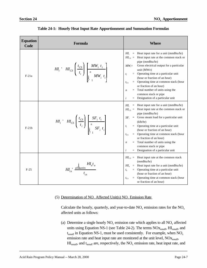
Section 24 NOx Apportionment
Acid Rain Program Policy Manual -- March 28, 2000 Page 24-7
HIi ' HICS
tCS
ti
MWi t i
jn
i' 1MWi ti
HIi ' HICS
tCS
t i
SFi ti
jn
i'1SFi t i
Table 24-1: Hourly Heat Input Rate Apportionment and Summation Formulas
EquationCode
Formula Where
F-21a
HIi = Heat input rate for a unit (mmBtu/hr)HICS = Heat input rate at the common stack or
pipe (mmBtu/hr)MWi= Gross electrical output for a particular
unit (MWe)ti = Operating time at a particular unit
(hour or fraction of an hour)tCS = Operating time at common stack (hour
or fraction of an hour)n = Total number of units using the
common stack or pipei = Designation of a particular unit
F-21b
HIi = Heat input rate for a unit (mmBtu/hr)HICS = Heat input rate at the common stack or
pipe (mmBtu/hr)SFi = Gross steam load for a particular unit
(klb/hr)ti = Operating time at a particular unit
(hour or fraction of an hour)tCS = Operating time at common stack (hour
or fraction of an hour)n = Total number of units using the
common stack or pipei = Designation of a particular unit
F-25 HIcs'j
all&unitsHIutu
tcs
HICS = Heat input rate at the common stack(mmBtu/hr)
HIu = Heat input rate for a unit (mmBtu/hr)tu = Operating time at a particular unit
(hour or fraction of an hour)tCS = Operating time at common stack (hour
or fraction of an hour)
(5) Determination of NOx Affected Unit(s) NOx Emission Rate
Calculate the hourly, quarterly, and year-to-date NOx emission rates for the NOx
affected units as follows:
(a) Determine a single hourly NOx emission rate which applies to all NOx affectedunits using Equation NS-1 (see Table 24-2). The terms NOxnonaff, HInonaff, andtnonaff in Equation NS-1, must be used consistently. For example, when NOx
emission rate and heat input rate are monitored at the unit level, NOxnonaff,HInonaff, and tnonaff are, respectively, the NOx emission rate, heat input rate, and

NOx Apportionment Section 24
Page 24-8 Acid Rain Program Policy Manual -- March 28, 2000
operating time for an individual NOx nonaffected unit. When a group of NOx
nonaffected units is monitored at a secondary common stack, NOxnonaff,HInonaff, and tnonaff are, respectively, the NOx emission rate, heat input rate, andoperating time at the secondary common stack.
(b) Record, but do not report, the hourly NOx emission rates determined fromEquation NS-1 for the NOx affected units. Maintain these data in a formatsuitable for inspection. It is sufficient to record these values in your DAHS ifthey can be retrieved upon request during an audit.
(c) Calculate the quarterly and year-to-date NOx emission rate for each NOx
affected unit using Equation F-9 in Appendix F of 40 CFR Part 75. Reportthese values as described in Policy Question 24.9.
Table 24-2: Hourly NOx Apportionment Formula for NOx Affected Units Using the Subtractive Methodology
EquationCode
Formula Where
NS-1 NOxaff
NOxCS HICS tCS NOxnonaff HInonaff tnonaffall nonafected
HIaff taffallaffected
=
× × − × ×
−∑
×∑
( )
( )
NOxaff = Hourly NOx emission rate forthe NOx affected units(lb/mmBtu)
NOxCS = Hourly NOx emission rate at thecommon stack for the quarter(lb/mmBtu)
HIcs = Hourly heat input rate at thecommon stack (mmBtu/hr)
tCS = Common stack operating time(hr)
NOxnonaff = Hourly NOx emission rate at theNOx nonaffected unit or secondcommon stack. (lb/mmBtu)
HInonaff = Hourly heat input for the NOx
nonaffected unit (mmBtu)tnonaff = NOx nonaffected unit or second
common stack
B. Simple NOx Apportionment
(1) Summary of Method and Basis for Approval
Under simple NOx apportionment, the hourly NOx emission rate and heat inputrate are monitored at the common stack and the hourly heat input rates for the

Section 24 NOx Apportionment
Acid Rain Program Policy Manual -- March 28, 2000 Page 24-9
individual units in the configuration are determined by direct measurement or byapportionment. The hourly emission rate of the NOx affected unit(s) is calculatedby dividing the total NOx mass emissions from all units (in lb) by the total heat input(in mmBtu) from only the NOx affected units.
This methodology is environmentally beneficial because it assures compliance ofthe NOx affected units, by overestimating the NOx emission rates for these units. The method assumes that all of the NOx mass emissions measured in the commonstack come from the NOx affected units (i.e., that the NOx nonaffected unitscontribute zero NOx emissions to the total NOx emissions measured at thecommon stack). The methodology may also provide environmental benefits byencouraging owners and operators of NOx affected units to lower NOx emissionsat the NOx affected units.
Despite these environmentally beneficial aspects, approval of this methodologymust still be on a case-by-case basis. Section 75.17(a)(iii)(B) requires "completeand accurate" estimation of the regulated emissions (i.e., for the emissions from theNOx affected units). EPA must therefore make a case-by-case determination ofwhether the assumption that all emissions come from the NOx affected units willcause significant error that may preclude the use of this option.
EPA anticipates that simple NOx apportionment will likely be used for commonstack configurations involving low capacity, small, or low emitting NOx nonaffectedunits.
(2) Main Common Stack Monitoring Requirements
(a) Monitor the hourly NOx emission rate at the main common stack using a NOx-diluent CEMS.
(b) Determine the hourly heat input rate at the main common stack using a flowmonitor and a diluent monitor.
(3) Heat Input Rate Determination for the Individual Units
Determine the hourly heat input rate for each unit which exhausts to the maincommon stack (i.e., both NOx affected and NOx nonaffected units), using any ofthe following methods:
(a) Install a flow monitor and a diluent monitor in the duct leading from the unit tothe main common stack; or

NOx Apportionment Section 24
Page 24-10 Acid Rain Program Policy Manual -- March 28, 2000
(b) Use a fuel flowmeter and the procedures of Appendix D (oil or gas-fired unitsonly), to determine the heat input rate at the unit; or
(c) Monitor the heat input rate for a group of NOx nonaffected units at asecondary common stack (see Definitions section, above) using a flow monitorand diluent monitor, and then apportion the heat input rate measured at thesecondary common stack to the individual units, using Equation F-21a or F-21b. Replace the term tCS in Equation F-21a or F-21b with the term tCS*,where tCS* is the stack operating time at the secondary common stack. Also,in the summation term in the denominator of Equation F-21a or F-21b, includeonly the hourly unit loads for the units associated with the secondary commonstack.
Note that the restriction under Paragraph (B)(3)(e) of this Policy Question onthe use of Equations F-21a and F-21b does not apply in this case; or
(d) Monitor the heat input rate at a common pipe which serves a group of NOx
nonaffected gas or oil fired units using the procedures of Appendix D. In thiscase, determine the individual unit heat input rates using Equation F-21a or F-21b.
Note that the restriction under Paragraph (B)(3)(e), below, on the use ofEquations F-21a and F-21b does not apply in this case; or
(e) Use Equation F-21a or F-21b to apportion the heat input rate measured at themain common stack to all units (i.e., both NOx affected and NOx nonaffectedunits.
Note that this method may only be used if the following condition is met: allunits exhausting to the main common stack combust the same type of fuel anduse the same F-factor.
(4) Hourly Heat Input Rate and Operating Time Reporting for all Units
Report hourly heat input rate and operating time in RT 300 for the main commonstack, any secondary common stack(s), any common pipe(s) and for each unit inthe configuration (i.e.,both NOx affected and NOx nonaffected units). Determinethe hourly heat input rates for the main common stack, secondary commonstack(s), common pipe(s) and for the individual units as described in Paragraphs(B)(2) and (B)(3) of this Policy Question.
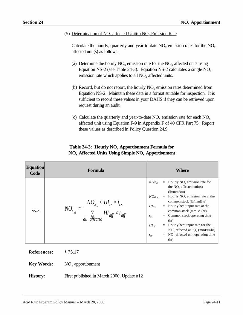
Section 24 NOx Apportionment
Acid Rain Program Policy Manual -- March 28, 2000 Page 24-11
(5) Determination of NOx affected Unit(s) NOx Emission Rate
Calculate the hourly, quarterly and year-to-date NOx emission rates for the NOx
affected unit(s) as follows:
(a) Determine the hourly NOx emission rate for the NOx affected units usingEquation NS-2 (see Table 24-3). Equation NS-2 calculates a single NOx
emission rate which applies to all NOx affected units.
(b) Record, but do not report, the hourly NOx emission rates determined fromEquation NS-2. Maintain these data in a format suitable for inspection. It issufficient to record these values in your DAHS if they can be retrieved uponrequest during an audit.
(c) Calculate the quarterly and year-to-date NOx emission rate for each NOx
affected unit using Equation F-9 in Appendix F of 40 CFR Part 75. Reportthese values as described in Policy Question 24.9.
Table 24-3: Hourly NOx Apportionment Formula for NOx Affected Units Using Simple NOx Apportionment
EquationCode
Formula Where
NS-2 NONO HI t
HI txx cs cs
aff affall affected
aff
cs=× ×
×∑−
NOxaff = Hourly NOx emission rate forthe NOx affected unit(s)(lb/mmBtu)
NOxCS = Hourly NOx emission rate at thecommon stack (lb/mmBtu)
HICS = Hourly heat input rate at thecommon stack (mmBtu/hr)
tCS = Common stack operating time(hr)
HIaff = Hourly heat input rate for theNOx affected unit(s) (mmBtu/hr)
taff = NOx affected unit operating time(hr)
References: § 75.17
Key Words: NOx apportionment
History: First published in March 2000, Update #12
NOx Apportionment Section 24
Page 24-12 Acid Rain Program Policy Manual -- March 28, 2000
Question 24.3
Topic: Reporting of Hourly Heat Input Rate
Question: How do I determine hourly heat input rate for the NOx affected and NOx nonaffectedunits in the configuration described in Question 24.2?
Answer: A. Heat Input Rate Measured at the Main Common Stack Only
For a qualifying configuration under Section A (subtractive apportionment) or SectionB (simple apportionment) of Policy Question 24.2, in which heat input rate is measuredonly at the main common stack, apportion the hourly heat input rate at the commonstack to each of the units in the configuration (both NOx affected and NOx nonaffectedunits) using Equation F-21a or F-21b in Appendix F of 40 CFR Part 75, for eachstack operating hour (i.e., each hour in which fuel is combusted by any unit in theconfiguration). The summation term in the denominator of these equations must includeall unit loads (for both the NOx affected and NOx nonaffected units).
B. Heat Input Rate Measured at the Main Common Stack and the NOx
Nonaffected Unit(s)
Use the procedures of this section to determine the heat input rate at the NOx affectedunits only when heat input rate is monitored or measured at both the main commonstack and at the individual NOx nonaffected units (or at a secondary common stackserving only the NOx nonaffected units).
(1) For all hours in which any NOx affected unit is operating, use Equation SS-3a (seeTable 24-2) to calculate the total heat input to the NOx affected unit(s).
The term on the left side of the minus sign in Equation SS-3a is the hourly total heatinput (mmBtu) at the main common stack and is the product of the measured heatinput rate in RT 300/36 and the stack operating time in RT 300/18.
The term on the right side of the minus sign is the total hourly heat input for theNOx nonaffected units and is the sum of the products of the measured RT 300/36heat input rates (as determined under Question 24.2) and the RT 300/18 unitoperating times for all of the NOx nonaffected units.
When a group of NOx nonaffected units is monitored at a single location, then, forthose units, replace the term HInonaff tnonaff in Equation SS-3a with the term HICS*
tCS*, where HICS* is the hourly heat input rate measured at the NOx nonaffected

Section 24 NOx Apportionment
Acid Rain Program Policy Manual -- March 28, 2000 Page 24-13
units’ monitoring location (designated as a secondary common stack) and tCS* isthe stack operating time at the secondary common stack.
Use the guidelines in the following three scenarios to ensure proper application ofEquation SS-3a:
Scenario #1. For any hour in which the total heat input in mmBtu measured at themain common stack is greater than the total heat input of the NOx nonaffectedunit(s), use Equation SS-3a to obtain the total hourly heat input for the NOx
affected units.
For each hour in which Scenario # 1 applies, calculate the individual NOx affectedunit heat rates using Equation SS-3b (see Table 24-2). Note that the summationterm in the denominator of Equation SS-3b includes only the hourly loads for theNOx affected unit(s).
Scenario #2. For any hour in which the total heat input at the main common stackis less than or equal to the total heat input for the NOx nonaffected unit(s), causingEquation SS-3a to give a negative or zero total heat input value for the NOx
affected units, follow these procedures:
(a) Invalidate the result obtained from Equation SS-3a;
(b) Consider the heat input rate measured at the main common stack to becorrect;
(c) Disregard all heat input rate(s) measured at the NOx nonaffected unit(s); and
(d) Apportion the heat input rate measured at the main common stack to all units(NOx affected and NOx nonaffected) in the subtractive stack configuration,using Equation F-21a or F-21b.
Scenario # 3. For any hour in which only NOx affected units are operating, setthe summation term in Equation SS-3a equal to zero, so that the total heat input forthe NOx affected units equals the heat input measured at the main common stack. Then, use Equation SS-3b to determine the hourly heat input rate for each NOx
affected unit.
(2) For any hour in which only NOx nonaffected units are exhausting to the commonstack, do not use Equation SS-3a. Assign a value of zero to the heat input ratesfor the NOx affected units. Then, for the NOx nonaffected units:

NOx Apportionment Section 24
Page 24-14 Acid Rain Program Policy Manual -- March 28, 2000
(a) Disregard all measured heat input rate values for the NOx nonaffected units;and
(b) Assume that the heat input rate at the main common stack is correct andapportion this heat input rate to the NOx nonaffected units using Equation F-21a or F-21b.
Table 24-4: Hourly Heat Input Formulas for NOx Affected Units
EquationCode
Formula Where
SS-3a HItot HI t HI taff hr CS CS nonaff nonaffall nonaff
−−
= − ∑
HItotaff-hr= Total hourly heat input for theNOx affected units (mmBtu)
HICS = Hourly heat input rate at thecommon stack (mmBtu/hr)
HInonaff = Hourly heat input rate for aparticular NOx nonaffectedunit (mmBtu/hr)
tCS = Operating time for thecommon stack (hr)
tnonaff = Operating time for a particularNOx nonaffected unit (hr)
SS-3b HIt
HItotL t
L taffi
aff hri i
iall aff
i= × − ×
−∑
1
HIaff = Hourly heat input rate for aparticular NOx affected unit(mmBtu/hr)
HItotaff-hr= Total hourly heat input for allNOx affected units (mmBtu)
ti = Operating time for a particularNOx affected unit (hr)
Li = Hourly unit load for aparticular NOx affected unit inthe subtractive stackconfiguration (MW or klb ofsteam per hour)
References: § 75.16(e)
Key Words: Heat input
History: First published in March 2000, Update #12

Section 24 NOx Apportionment
Acid Rain Program Policy Manual -- March 28, 2000 Page 24-15
Question 24.4
Topic: Common Stack NOx Apportionment for Other Configurations
Question: Question 24.2 addresses only common stack NOx apportionment for a configurationconsisting of NOx affected and NOx nonaffected units. What are the similarities anddifferences in the common stack NOx apportionment methodologies for otherconfigurations? In particular, address the following cases: (1) a configuration in whichAcid Rain units share a common stack with non-Acid Rain units; and (2) aconfiguration in which a group of NOx affected units share a common stack.
Answer: For the first configuration (Acid Rain and non-Acid Rain units sharing a commonstack), the procedures and mathematics are exactly analogous to the case described inQuestion 24.2. Simply replace the term "NOx affected unit" with the term, "Acid Rainunit" and replace the term "NOx nonaffected unit" with the term "non-Acid Rain unit."
However, the second configuration (NOx affected units sharing a common stack) is notanalogous to the case described in Question 24.2, as there are no NOx nonaffectedunits. Options (1), (2), and (3) in BACKGROUND section (I)(B), above, apply. IfOption (3) is chosen, the owner or operator must submit a petition for an alternateapportionment method, satisfactory to the Administrator, ensuring complete andaccurate estimation of emissions and no underestimation of any unit’s emissions.
References: § 75.17
Key Words: NOx apportionment
History: First published in March 2000, Update #12
Question 24.5
Topic: Monitoring Plan Requirements
Question: What are the monitoring plan requirements for the common stack NOx apportionmentdescribed in Question 24.2?
Answer: For all units, including the NOx nonaffected unit(s), report all standard unit-level recordtypes including unit data, program data, monitoring methodologies, controls, and fuels(RTs 504, 505, 506, 585, 586, and 587).

NOx Apportionment Section 24
Page 24-16 Acid Rain Program Policy Manual -- March 28, 2000
For the main common stack serving both NOx affected and NOx nonaffected units,define the relationship between the stack and units in RTs 503 and submit all thestandard monitoring plan information to support continuous emission monitoringsystems (CEMS) at the common stack (RTs 510, 520, 530, 531, 535, and 536, asapplicable). Report a RT 503 for each of the units served by the common stack.
For each NOx nonaffected unit monitoring location, report all the standard monitoringplan information to support the CEMS, other monitoring systems or apportionmentformulas at that location (RTs 510, 520, 530, 531, 535, 536, and 540). For eachNOx affected unit, report the appropriate heat input apportionment formula in RT 520(see Question 24.3).
If the combined emissions from a group of units are monitored at a "secondarycommon stack" (see Definitions, above), report one RT 503 for each unit in the group,defining the relationship between the unit and the secondary common stack.
If a group of oil or gas-fired NOx nonaffected units receives fuel from a common pipe,report one RT 503 for each unit in the group that defines the relationship between theunit and the common pipe.
If you petition and receive approval to use a minimum NOx rate for missing datapurposes, include the approved minimum rate in RT 531, using the code "MNNX" asthe parameter and "APP" (approved) as the source of data code (see Policy Question24.11).
Also include a narrative description of the NOx apportionment configuration andreporting approach in RTs 910 (see Policy Question 24.12).
References: EDR v2.1 Reporting Instructions
Key Words: Monitoring plans
History: First published in March 2000, Update #12
Question 24.6
Topic: QA Requirements
Question: When common stack NOx apportionment is used, what are the quality assurancerequirements for monitoring systems installed in the duct(s) leading from NOx
nonaffected unit(s) or non-Acid Rain unit(s) to the common stack?
Section 24 NOx Apportionment
Acid Rain Program Policy Manual -- March 28, 2000 Page 24-17
Answer: The monitoring systems located at the NOx nonaffected unit or non-Acid Rain unitmust be fully certified in accordance with testing required under § 75.21 and AppendixB to 40 CFR Part 75. The bias test requirement in Section 7.6 of Appendix A to 40CFR Part 75 also applies to NOx and flow rate monitoring systems installed on NOx
nonaffected units.
References: EDR v2.1 Reporting Instructions
Key Words: BAF, Quality assurance
History: First published in March 2000, Update #12
Question 24.7
Topic: Unit/Stack EDRs
Question: Should all of the units, pipes and stacks involved in a common stack NOx
apportionment configuration be included together in the same quarterly report?
Answer: Yes. Based on prior EPA guidance, all stack or pipe-level and associated unit-leveldata should be contained in a single quarterly report.
References: EDR v2.1 Reporting Instructions
Key Words: Electronic report formats
History: First published in March 2000, Update #12
Question 24.8
Topic: Reporting of Hourly NOx Emission Rate and Heat Input Rate Data
Question: How do I report hourly data for a common stack NOx apportionment?
Answer: Report hourly NOx emission rate and heat input rate data for a common stack NOx
apportionment at each location where NOx emission rate and/or heat input rate ismeasured (i.e., at the main common stack, any secondary common stack(s), anycommon pipe(s) and each unit monitoring location), as you would for any other NOx

NOx Apportionment Section 24
Page 24-18 Acid Rain Program Policy Manual -- March 28, 2000
monitoring configuration. Report only the measured data. Do not report hourlyapportioned NOx emission rate values for the NOx affected units in RTs 320.
If you have additional reporting questions, contact EPA.
References: EDR v2.1 Reporting Instructions
Key Words: Electronic report formats
History: First published in March 2000, Update #12
Question 24.9
Topic: Cumulative Emissions Reporting
Question: What quarterly and annual NOx emission rate data, operating hours, and total heatinput data should I report in RTs 301 for the common stack NOx apportionmentdescribed in Policy Question 24.2?
Answer: First note that this question does not cover reporting of CO2 or SO2 mass emissions.
Report separate RTs 301 for the main common stack, any secondary commonstack(s), any common pipe(s), and each unit in the common stack configuration.
Two examples are provided for reference:
(1) If there is a main common stack, one NOx affected unit, and one NOx nonaffectedunit in the configuration, report three RTs 301 in each quarterly report: one for thecommon stack, one for the NOx affected unit, and one for the NOx nonaffectedunit.
(2) If there is a main common stack through which four units exhaust to theatmosphere, two of which are NOx nonaffected and two of which are NOx
affected, and if the NOx nonaffected units are monitored at a secondary commonstack location, report six record types 301, one at the main common stack, one atthe secondary common stack, and one for each unit.
In the RT 301 for the main common stack, report the quarterly and year-to-date NOx
emission rates (lb/mmBtu), operating hours, and heat input (mmBtu) values derivedfrom the common stack monitors. Calculate all quarterly and cumulative emissions and
Section 24 NOx Apportionment
Acid Rain Program Policy Manual -- March 28, 2000 Page 24-19
heat input values in accordance with the applicable sections of the EDR v2.1 ReportingInstructions.
In RT 301 for each NOx nonaffected unit, report all required quarterly and cumulativeheat input data (either measured or apportioned as appropriate) and operating hours. Also report the NOx emission rate if it is individually monitored.
In the RT 301 for a secondary common stack location at which a group of NOx
nonaffected units is monitored (if applicable), report all quarterly and cumulative NOx
emission rate, operating hours, and heat input values derived either from the hourlyCEMS measurements made at the monitoring location, or apportioned to that location.
In the RT 301 for a common pipe, report the quarterly and cumulative heat inputvalues and operating hours derived from the hourly heat input rate measurements andfuel usage times at the common pipe.
In RT 301 for each NOx affected unit, report the quarterly and cumulative heat inputand operating hours that were derived using one of the accepted methodologies in thispolicy. Also report the NOx emission rate, as apportioned to the unit.
References: EDR v2.1 Reporting Instructions
Key Words: Electronic report formats, NOx apportionment
History: First published in March 2000, Update #12
Question 24.10
Topic: Missing Data Requirements
Question: What missing data requirements apply in the common stack NOx apportionment stackconfiguration described in Question 24.2?
Answer: For the common stack, use the standard missing data procedures in § 75.33.
For monitors located at either the individual NOx nonaffected units or at a secondarycommon stack serving only the NOx nonaffected units use "inverse" missing dataprocedures for NOx, CO2 and flow rate missing data (i.e., substitute the 10thpercentile value when the standard missing data procedures in § 75.33 require the 90thpercentile value, use the 5th percentile value in lieu of the 95th percentile value, use theminimum value in the look back periods instead of the maximum value and use zeros

NOx Apportionment Section 24
Page 24-20 Acid Rain Program Policy Manual -- March 28, 2000
for the minimum potential NOx emission rate or minimum potential flow rate for anyhours in which maximum potential values would ordinarily be used under Subpart D ofPart 75). The owner or operator may petition the Administrator under § 75.66 to useminimum potential values other than zero.
If O2 data, rather than CO2 data is used in the heat input rate calculations, use the"regular" missing data algorithm, rather than the inverse algorithm, to provide substituteO2 data for the heat input rate determinations.
For moisture missing data, use the regular missing data algorithm, unless Equation 19-3, 19-4, or 19-8 is used for NOx emission rate determination, in which case, use theinverse missing data algorithm.
Use the missing data method of determination codes specified in Table 4a in Part 75.
References: § 75.33, § 75.66
Key Words: Missing data
History: First published in March 2000, Update #12
Question 24.11
Topic: Representation of NOx Apportionment in EDR
Question: What record types do I use in my quarterly report submittal to identify the agreed uponmethod of calculating the overall NOx emission rate for the NOx affected units when Iam using either of the common stack NOx apportionment methodologies described inQuestion 24.2?
Answer: Use RT 910 (cover letter text record) to identify the method used to calculate the NOx
emission rate for compliance purposes. The following format (in italics) should be usedto identify how the NOx emission rate is determined for the NOx affected and NOx
nonaffected units.
Section 24 NOx Apportionment
Acid Rain Program Policy Manual -- March 28, 2000 Page 24-21
I. This common stack EDR submission for the following units uses an approvedNOx apportionment methodology.
Main Common Stack: [Stack ID]NOx affected unit IDs: [list IDs separated by commas]NOx nonaffected unit IDs: [list IDs separated by commas]
Secondary Common Stack(if applicable): [Stack ID]NOx nonaffected unit IDs: [list IDs separated by commas]
Common Pipe (if applicable): [Pipe ID]NOx nonaffected unit IDs: [list IDs separated by commas]
II. Method used to determine NOx emission rate at the NOx affected units:
Report one of the following:
(1) Subtractive apportionment methodology using Equation NS-1; or
(2) Simple NOx apportionment using Equation NS-2.
III. Heat input methodology for the NOx nonaffected units:
Report at least one of the following:
(1) Duct level flow monitor and diluent monitor; or
(2) Appendix D fuel flowmeter; or
(3) Common stack heat input apportionment using Equation F-21a or F-21b.
References: EDR v2.1 Reporting Instructions
Key Words: Electronic report formats, NOx apportionment
History: First published in March 2000, Update #12

NOx Apportionment Section 24
Page 24-22 Acid Rain Program Policy Manual -- March 28, 2000
Question 24.12
Topic: Approvable NOx Apportionment Methodologies
Question: Are these the only approvable NOx apportionment methodologies?
Answer: This policy guidance does not preclude other NOx apportionment methodologies beingconsidered or approved.
References: N/A
Key Words: NOx apportionment
History: First published in March 2000, Update #12
Question 24.13
Topic: NOx Apportionment Methodologies Examples
Question: Are there any examples of units which currently have NOx apportionment situations?
Answer: Several examples will be provided in the future to describe actual NOx apportionmentsituations to help explain reporting for these situations.
References: N/A
Key Words: NOx apportionment
History: First published in March 2000, Update #12

Acid Rain Program Policy Manual -- March 28, 2000 Page 25-i
SECTION 25APPENDIX D
Page
25.1 REVISED GCV Sampling Frequency for Pipeline Natural Gas . . . . . . . . . . 25-1
25.2 REVISED Measuring Gas Sulfur Content . . . . . . . . . . . . . . . . . . . . . . . . . . 25-1
25.3 REVISED Diesel Fuel Sampling . . . . . . . . . . . . . . . . . . . . . . . . . . . . . . . . . 25-2
25.4 REVISED Fuel Usage Time . . . . . . . . . . . . . . . . . . . . . . . . . . . . . . . . . . . . 25-2
25.5 Appendix D Fuel Sampling -- Usage of Multiple Fuels . . . . . . . . . . . . . . . . . . 25-3
25.6 REVISED Appendix D Fuel Sampling -- Time for Results . . . . . . . . . . . . . . 25-4
25.7 REVISED Backup Fuel . . . . . . . . . . . . . . . . . . . . . . . . . . . . . . . . . . . . . . . 25-4
25.8 Use of Billing Fuel Flowmeter . . . . . . . . . . . . . . . . . . . . . . . . . . . . . . . . . . . . . 25-5
25.9 Vendor-supplied Sulfur Values . . . . . . . . . . . . . . . . . . . . . . . . . . . . . . . . . . . . 25-5
25.10 Certified Fuel Flowmeter -- Emergency Fuel Exemption . . . . . . . . . . . . . . . . . 25-6
25.11 Missing Data Substitution -- Use of Multiple Fuels . . . . . . . . . . . . . . . . . . . . . 25-8
25.12 Failure of Fuel Flow-to-load Test . . . . . . . . . . . . . . . . . . . . . . . . . . . . . . . . . . 25-8
25.13 Use of Quarterly Operating Data in Fuel Flow-to-load Test . . . . . . . . . . . . . . . 25-9
25.14 Use of Quarterly Fuel Flow-to-load Test . . . . . . . . . . . . . . . . . . . . . . . . . . . . 25-9
25.15 Alternative Calibration Method for Coriolis Meters . . . . . . . . . . . . . . . . . . . . 25-10

Appendix D Section 25
Page 25-ii Acid Rain Program Policy Manual -- March 28, 2000
[This page intentionally left blank]
Section 25 Appendix D
Acid Rain Program Policy Manual -- March 28, 2000 Page 25-1
Question 25.1 REVISED
Topic: GCV Sampling Frequency for Pipeline Natural Gas
Question: If I have a unit using a default emission rate to calculate SO2 emissions from pipelinenatural gas, how often does fuel sampling and analysis have to be performed todetermine the GCV?
Answer: For gas, monthly fuel sampling and analysis is required for every month that gaseousfuel is combusted. The sampling and analysis may be done either by the owner oroperator or by the fuel supplier. This requirement does not apply for any month inwhich pipeline natural gas is combusted for a period less than 48 hours, provided thatat least one analysis for GCV is done each quarter that the unit operates. Oil samplingstill must be done in accordance with the procedures in Section 2.2 of Appendix D.
References: Appendix D, Section 2.3.4.1; Appendix F, Section 5.5
Key Words: Excepted methods, Gas-fired units, SO2 monitoring
History: First published in July 1995, Update #6 as Question 2.7; revised and renumbered inOctober 1999 Revised Manual
Question 25.2 REVISED
Topic: Measuring Gas Sulfur Content
Question: Is it permissible for a gas supplier to measure the amount of sulfur-containingcompounds added to pipeline natural gas instead of sampling the sulfur content in thepipeline natural gas?
Answer: No. Appendix D requires sampling of the gaseous fuel by specified methods.
References: Appendix D, Section 2.3.3.1.2
Key Words: Excepted methods, Fuel sampling, SO2 monitoring
History: First published in November 1995, Update #7 as Question 2.8; revised andrenumbered in October 1999 Revised Manual

Appendix D Section 25
Page 25-2 Acid Rain Program Policy Manual -- March 28, 2000
Question 25.3 REVISED
Topic: Diesel Fuel Sampling
Question: How are we to do as-delivered fuel sampling of diesel fuel, and which sulfur value isused to calculate SO2 mass emissions? Can we just use the sulfur content from ourmost recent delivery, as provided by our vendor?
Answer: Appendix D, Section 2.2.4.3 states: "Oil sampling may be performed either by theowner or operator of an affected unit, an outside laboratory, or a fuel supplier,provided that samples are representative and that sampling is performed according toeither the single tank composite sampling procedure or the all-levels samplingprocedure in ASTM D4057-88. . ."
This may be accomplished by taking a sample from the:
(1) Shipment tank or container upon receipt.
(2) Supplier's storage container that holds the fuel (if fuel is added to the container, anew sample must be taken).
SO2 mass emissions then should be calculated using either the highest valuesampled during the previous calendar year or the maximum value indicated in thefuel supply contract unless the actual value obtained from the most recent sample ishigher.
References: Appendix D, Section 2.2.4.3
Key Words: Excepted methods, Fuel sampling, Oil-fired units, SO2 monitoring
History: First published in November 1995, Update #7 as Question 2.9; revised andrenumbered in October 1999 Revised Manual
Question 25.4 REVISED
Topic: Fuel Usage Time
Question: Do invalid one-minute fuel flow data points get counted in the determination of thehourly fuel usage time? For example, if we have valid one-minute data from minute 1through 28, invalid data from minute 29 through 35 and valid "0" data (fuel off) fromminute 36 through 60, what is the fuel usage time?

Section 25 Appendix D
Acid Rain Program Policy Manual -- March 28, 2000 Page 25-3
Answer: You may report the actual portion of each clock hour in which the unit combusted fuel,to the nearest hundredth of an hour (0.58 in this example, based on minutes 1 through35), or you may report the number of quarter hours in which the unit combusted fuel,rounded up to the next highest quarter hour (0.75 in this example). Note that while thehourly average fuel flow rate is based upon the valid data points collected while the fuelwas being burned (i.e., the average of the data collected between minutes 1 and 28),the fuel usage time is based upon the time during which fuel was burned regardless ofwhether or not valid fuel flow rate data were obtained.
References: Appendix D; RT 302, RT 303
Key Words: Excepted methods, Fuel sampling, SO2 monitoring
History: First published in November 1995, Update #7 as Question 2.10; revised andrenumbered in October 1999 Revised Manual
Question 25.5
Topic: Appendix D Fuel Sampling -- Usage of Multiple Fuels
Question: Section 2.2.4 of Appendix D states that if multiple oil supplies with different sulfurcontents are combusted in one day, the utility should sample the highest sulfur contentfuel. How do we know which sulfur content is higher until it is sampled and analyzed?
Answer: If different types of fuel with different expected sulfur contents are combusted on oneday (e.g., #2 fuel oil and #6 fuel oil), the utility may sample only the type of fuel withthe expected higher sulfur content. If the same type of fuel from different suppliers areburned, the utility must sample both fuels to determine which has a higher sulfurcontent.
References: Appendix D, Section 2.2.4.1
Key Words: Excepted methods, Fuel sampling, Oil-fired units, SO2 monitoring
History: First published in November 1995, Update #7 as Question 2.11; renumbered inOctober 1999 Revised Manual

Appendix D Section 25
Page 25-4 Acid Rain Program Policy Manual -- March 28, 2000
Question 25.6 REVISED
Topic: Appendix D Fuel Sampling -- Time for Results
Question: Appendix D requires results of sampling within 30 days of sampling. Does this meanon site or entered into the DAHS for processing?
Answer: The results of sampling should be available on site at the plant within 30 days ofsampling. Also, in the event of an audit, EPA may request that these values be madeavailable to the Agency within five days of the request. As a standard operatingprocedure it is acceptable to enter the data at the end of the quarter. However, in theevent of an onsite audit by EPA or State agency staff, the operator must be able toenter the data in the DAHS and generate the calculated values. Furthermore, the datamust be retrievable from the DAHS the day of an onsite audit.
References: Appendix D, Sections 2.2.8, 2.3.3.1.4
Key Words: DAHS, Excepted methods, Fuel sampling, SO2 monitoring
History: First published in November 1995, Update #7 as Question 2.12; renumbered inOctober 1999 Revised Manual
Question 25.7 REVISED
Topic: Backup Fuel
Question: What is backup fuel, as referred to in various sections of 40 CFR Part 75? DoAppendix D fuel flowmeters measuring backup fuel qualify for less frequent fuelflowmeter calibrations?
Answer: The term backup fuel is defined in § 72.2. For Part 75, backup fuel means "the fuelprovides less than 10.0 percent of the heat input to a unit during the three calendaryears prior to certification testing of the primary fuel and the fuel provides less than15.0 percent of the heat input to a unit in each of those three calendar years." Forexample, for a gas-fired unit, oil may be a backup fuel.
Fuel flowmeters that measure the flow of backup fuel are calibrated at the samefrequency as flowmeters that measure the flow of primary fuel (i.e., once every fourfuel flowmeter QA operating quarters (as that term is defined in § 72.2)). (SeeSection 2.1.6(a) of Appendix D.)

Section 25 Appendix D
Acid Rain Program Policy Manual -- March 28, 2000 Page 25-5
References: § 72.2, Appendix D, Section 2.1.6(a)
Key Words: Backup fuel, Excepted methods, Flow monitoring, Fuel sampling, SO2 monitoring
History: First published in March 1996, Update #8 as Question 3.11; revised and renumberedin October 1999 Revised Manual
Question 25.8
Topic: Use of Billing Fuel Flowmeter
Question: Can we use a billing fuel flowmeter for oil?
Answer: Yes, provided that the requirements of Section 2.1.4.2 of Appendix D are met.
References: Appendix D, Section 2.1.4.2
Key Words: Excepted methods
History: First published in October 1999 Revised Manual
Question 25.9
Topic: Vendor-supplied Sulfur Values
Question: Can we use vendor-supplied values for Appendix D fuel sampling requirements (e.g.,percent sulfur)?
Answer: Yes.
References: Appendix D, Sections 2.2 and 2.3
Key Words: Excepted methods, Fuel sampling
History: First published in October 1999 Revised Manual

Appendix D Section 25
Page 25-6 Acid Rain Program Policy Manual -- March 28, 2000
Question 25.10
Topic: Certified Fuel Flowmeter -- Emergency Fuel Exemption
Question: Our plant generally burns only natural gas but also has the capability to burn oil. Section 2.1.4.3 of Appendix D has a new option for emergency fuels which does notrequire the use of a certified fuel flowmeter. Can you elaborate on how this monitoringoption is to be implemented?
Answer: First, the fuel must qualify as an emergency fuel as described in Appendix D Section2.1.4.3. This means accepting a permit restriction which limits the use of the fuel toemergency situations in which the primary fuel is not available. EPA considers thefollowing circumstances to be emergency situations: (1) if the supplier of the primaryfuel cannot provide that fuel (e.g., gas curtailment); and (2) if the primary fuel handlingsystem is inoperable and is being repaired. Note that the permit restriction may alsocontain provisions which allow the unit to combust the emergency fuel for short testperiods as a normal maintenance practice to verify that the unit can safely combust theemergency fuel.
If the necessary permit restriction is in place, then, according to Section 2.1.4.3 ofAppendix D, the use of a certified fuel flowmeter is not required when the emergencyfuel is combusted, and the maximum rated hourly heat input may be used for emissionsreporting. Use the following EDR reporting guidelines when this option is selected:
Reporting Data in RT 302
! In RT 302, report data in fields 1, 4, 13, 19, and 56 in the normal fashion.
! Do not define or report an emergency fuel flowmeter monitoring system in field 10. Leave this field blank.
! Also leave fields 32, 59, 69, 74, 75, 83, 88, and 92 blank.
! Report the maximum mass flow rate of oil for the unit in column 21 and report asource of data code of "4" in field 31. Calculate the maximum oil mass flow rateusing the following equation:
MFFRMHHI
GCVEmer
= × 106
(Equation EF-1)
Section 25 Appendix D
Acid Rain Program Policy Manual -- March 28, 2000 Page 25-7
Where:
MFFR = Maximum mass flow rate of oil for the unit (lb/hr)MHHI = Maximum rated hourly heat input rate for the unit as reported in RT 504
(mmBtu/hr).GCVEmer = Gross calorific value of the emergency fuel (Btu/lb). Use either a value
measured by one of the accepted sampling methods in Appendix D or use thedefault fuel GCV values in Table D-6 of Appendix D (i.e., 19,500 Btu/lb forresidual oil or 20,000 Btu/lb for diesel, kerosene or other distillate fuel oils ofgrades 1 or 2).
106 = Conversion factor from mmBtu to Btu
! Report the GCV of the oil in field 34, in units of Btu/lb.
! In column 44, report "0" if a measured value of fuel GCV is used or "1" if a defaultvalue is used.
! In column 45, report the unit heat input rate (i.e., the MHHI, as defined inEquation EF-1, above).
! In column 52, report the total unit operating time for the hour. Note that the heatinput rate in column 45, multiplied by the operating time in field 52 should equal thetotal hourly heat input reported for the unit in column 57 of RT 300.
! In field 89, always report "S" to indicate that a single fuel was combusted duringan hour when the emergency fuel is combusted. Do not attempt to account formultiple fuel combustion during any hour(s) in which the emergency fuel iscombusted.
! In column 90, report either the appropriate code for GCV sampling or code "8" ifa default GCV value is used.
Reporting SO2 Mass Emissions in RT 313
! In RT 313 report fields 1, 4, 13, 19, 30, and 37 (optional) in the normal way.
! Do not define or report an emergency fuel flowmeter monitoring system in field 10. Leave this field blank.
! In column 21, report the sulfur content of the oil. Report either a measured valueobtained by one of the sulfur sampling options in Appendix D or a default sulfurcontent from Table D-6 of Appendix D.
! In column 44, report either the sampling option used for the oil sulfur content orcode "8" for a default % sulfur value from Table D-6.

Appendix D Section 25
Page 25-8 Acid Rain Program Policy Manual -- March 28, 2000
References: Appendix D, Section 2.1.4.3
Key Words: Electronic report formats, Excepted methods, SO2 monitoring
History: First published in October 1999 Revised Manual
Question 25.11
Topic: Missing Data Substitution -- Use of Multiple Fuels
Question: There are Acid Rain-only sources that are reporting using EDR v1.3 but are having aproblem reporting SO2 mass emissions when burning two different oils or two differentgases during the same hour and doing missing data substitution for fuel flow rate for thesame hours. Can I use the EDR v2.1 Reporting Instructions when doing missing datasubstitution for RT 302 and RT 313 for oil and RT 303 and 314 for gas?
Answer: Yes, there are two situations where this is applicable. First, when burning two differentoils for the same hour and doing missing data substitution you should report a validmonitoring system ID in at least one of the RT 302 if the oil flow rate data are missingfor both oils. Report this same monitoring system ID in the companion RT 313. Second, when burning two different gases for the same hour and doing missing datasubstitution you should report a valid monitoring system ID in at least one of the RT303 if the gas flow rate data are missing for both fuels. Report this same monitoringsystem ID in the companion RT 314.
References: Appendix D
Key Words: Excepted methods, Missing data, SO2 monitoring, Reporting
History: First published in October 1999 Revised Manual
Question 25.12
Topic: Failure of Fuel Flow-to-load Test
Question: If we fail a quarterly fuel flow-to-load ratio test, what data are invalidated?
Answer: The data are invalidated starting with the first hour of the quarter following the quarterin which the test was failed.

Section 25 Appendix D
Acid Rain Program Policy Manual -- March 28, 2000 Page 25-9
References: Appendix D, Section 2.1.7.4(b)
Key Words: Data validity, Fuel flow-to-load test
History: First published in October 1999 Revised Manual
Question 25.13
Topic: Use of Quarterly Operating Data in Fuel Flow-to-load Test
Question: Under Appendix D, for a fuel flow-to-load test, why are we required to use more ofthe quarterly operating data than is required for the stack flow-to-load test?
Answer: The fuel flow-to-load ratio test requires the use of more of the quarterly data than thestack flow-to-load ratio test, because it is not tied to a baseline test like the stack flow-to-load test, which uses a RATA test at a specific load level as the baseline.
Note that EPA evaluated real fuel flow rate data and responded to comments on the1998 proposed rule by extending the allowable data exclusion to the lower 25% of therange of operation instead of the lower 10%.
References: Appendix D, Section 2.1.7.1(a)
Key Words: Excepted methods, Fuel flow-to-load
History: First published in March 2000, Update #12
Question 25.14
Topic: Use of Quarterly Fuel Flow-to-load Test
Question: May I perform the quarterly fuel flow-to-load ratio test (as described in Section 2.1.7of Appendix D) for one quarter and then change my mind and stop reporting theresults of that test in subsequent quarters?
Answer: Yes, as long as you fulfill the QA requirements for the fuel flowmeter. If, at thebeginning of the calendar quarter in which you decide to discontinue reporting the fuelflow-to-load ratio test results, a historical lookback shows that four or more "fuelflowmeter QA operating quarters" have passed since the last fuel flowmeter

Appendix D Section 25
Page 25-10 Acid Rain Program Policy Manual -- March 28, 2000
calibration, then you must recalibrate the fuel flowmeter prior to the end of the quarterin which the fuel flow-to-load ratio analysis is discontinued. If fewer than four "fuelflowmeter QA operating quarters" have passed since the last fuel flowmeter calibrationyou may wait until the "normal" deadline to perform the required recalibration.
Note, however, that if your decision to discontinue performing the quarterly fuel flow-to-load data analysis is based on the results of a failed fuel flow-to-load test, you maynot ignore these test results. In this case you must report the results of the failed testand you must follow the procedures of Appendix D, Section 2.1.7.4, "Consequencesof Failed Fuel Flow-to-Load Ratio Test." This applies even if the failed fuel flow-to-load test occurs prior to the completion of four fuel flowmeter QA operating quarters.
References: Appendix D, Sections 2.1.7.3, 2.1.7.4
Key Words: Excepted methods, Fuel flow-to-load test
History: First published in March 2000, Update # 12
Question 25.15
Topic: Alternative Calibration Method for Coriolis Meters
Question: Is a method for Coriolis meters going to be part of future technical corrections?
Answer: The Agency is not aware of any current voluntary consensus standards (ASTM, AGA,ANSI ISO, etc.) that provide an alternative method of calibration for Coriolis type fuelflowmeters. Therefore, the acceptable methods for calibrating Coriolis fuel flowmetersare the methods described in Appendix D, Section 2.1.5.2 (i.e., (1) calibration againsta reference meter installed in line with the Coriolis meter; or (2) laboratory calibration by the manufacturer).
References: Appendix D, Section 2.1.5.2
Key Words: Excepted methods
History: First published in March 2000, Update # 12

Acid Rain Program Policy Manual -- March 28, 2000 Page 26-i
SECTION 26APPENDIX E
Page
26.1 REVISED Appendix E -- Testing . . . . . . . . . . . . . . . . . . . . . . . . . . . . . . . 26-1
26.2 Excepted Methods -- Applicability . . . . . . . . . . . . . . . . . . . . . . . . . . . . . . . . 26-1
26.3 REVISED Excepted Methods -- Traverse Points . . . . . . . . . . . . . . . . . . . 26-2
26.4 Appendix E Testing and Common Stacks . . . . . . . . . . . . . . . . . . . . . . . . . . . 26-2
26.5 REVISED Appendix E -- Certification Applications . . . . . . . . . . . . . . . . . . 26-3
26.6 REVISED Requirements for Appendix E Testing for Gas-fired Units Burning Emergency Fuel . . . . . . . . . . . . . . . . . . . . . . . . . . . . . . 26-4
26.7 Appendix E -- NOx Correlation Curves . . . . . . . . . . . . . . . . . . . . . . . . . . . . 26-4
26.8 Appendix E -- Quality Assurance/Quality Control Parameters . . . . . . . . . . . . 26-5
26.9 REVISED Appendix E -- Maximum NOx Emission Rates . . . . . . . . . . . . . 26-6
26.10 Appendix E -- Redetermination of Correlation . . . . . . . . . . . . . . . . . . . . . . . 26-6
26.11 Appendix E -- Redetermination of Correlation . . . . . . . . . . . . . . . . . . . . . . . 26-7
26.12 Appendix E -- Calculation of 3,000 Hour Requirement . . . . . . . . . . . . . . . . . 26-8
26.13 Comparison of QA Parameters to Defined Ranges . . . . . . . . . . . . . . . . . . . . 26-8
26.14 F-factors for Process Gas, Other Gas, and Mixtures . . . . . . . . . . . . . . . . . . . 26-9
26.15 Reporting of NOx Emission After Fuel Change . . . . . . . . . . . . . . . . . . . . . . 26-10

Appendix E Section 26
Page 26-ii Acid Rain Program Policy Manual -- March 28, 2000
Page
26.16 Use of Default NOx Emission Factor . . . . . . . . . . . . . . . . . . . . . . . . . . . . . . . 26-10
26.17 Parameters Affecting NOx Emission Rate . . . . . . . . . . . . . . . . . . . . . . . . . . . 26-11
26.18 Appendix E - Calculation of 3,000 Hour Requirement . . . . . . . . . . . . . . . . . . 26-11
26.19 Calculation of Appendix E NOx Emission Rate Data Availability . . . . . . . . . . 26-12
Section 26 Appendix E
Acid Rain Program Policy Manual -- March 28, 2000 Page 26-1
Question 26.1 REVISED
Topic: Appendix E -- Testing
Question: In the procedures in Appendix E to Part 75, how many sample runs of Method 7Eneed to be run at each load level? How long does each run last?
Answer: Conduct three sample runs at each load level as stated in Section 2.1.2.3 ofAppendix E.
When the sampling points specified in Section 2.1.2.1 of Appendix E are used, the firstsampling point of each traverse should be sampled for at least one minute plus twicethe average measurement system response time. All other sampling points in eachtraverse should be performed for at least one minute plus the average measurementresponse time. However, if permission is obtained through a petition under § 75.66 touse fewer sampling points than are specified in section 2.1.2.1 of Appendix E, ensurethat the total sampling time for each test run is $ 15 minutes, and divide the totalsampling time for the run evenly among all sample points.
References: Appendix E, Section 2.1.2.3
Key Words: Excepted methods, NOx monitoring
History: First published in May 1993, Update #1 as Question 4.3; revised July 1995, Update#6; revised and renumbered in October 1999 Revised Manual
Question 26.2
Topic: Excepted Methods -- Applicability
Question: Can a gas-fired unit performing testing to meet the requirements of Appendix E beexempt from including this period of testing in the calculation of unit operating hours forthe purpose of determining eligibility as a peaking unit (or as a gas-fired unit)?
Answer: No. All unit operating hours, including those hours during the performance testsrequired to establish NOx-load correlations used for the Appendix E procedure mustbe included in the determination of continued eligibility as a peaking unit (or as a gas-fired unit).
References: § 75.12(d); Appendix E

Appendix E Section 26
Page 26-2 Acid Rain Program Policy Manual -- March 28, 2000
Key Words: Excepted Methods, NOx monitoring
History: First published in May 1993, Update #1 as Question 4.7; renumbered in October1999 Revised Manual
Question 26.3 REVISED
Topic: Excepted Methods - Traverse Points
Question: For NOx stack testing for Appendix E to Part 75, how should I select samplinglocations for each point in a traverse for each run?
Answer: For a stationary gas turbine (combustion turbine) or reciprocating engine, selectsampling points as specified in Method 20 in Appendix A to 40 CFR Part 60.
For a boiler, select sampling points as specified in Section 5.1, Method 3, in AppendixA to Part 60. The designated representative may petition the Administrator under§ 75.66 to use fewer traverse points than are specified by Method 3. The petitionmust include a proposed alternative sampling procedure and information demonstratingthat stratification is absent at the sampling location (see the stratification test inAppendix A to Part 75, Section 6.5.6.1).
References: 40 CFR Part 60, Appendix A; Part 75, Appendix A, Section 6.5.6.1; Part 75,Appendix E, Sections 2.1.2.1 and 2.1.2.2
Key Words: Excepted methods, NOx monitoring, Stack testing
History: First published in August 1994, Update #3 as Question 4.10; revised and renumberedin October 1999 Revised Manual
Question 26.4
Topic: Appendix E Testing and Common Stacks
Question: Two oil-fired units share a common stack. The utility wants to perform Appendix Etesting and then report the emissions from the units separately. Can they test the unitstogether at the common stack and then report the data separately for each unit?
Section 26 Appendix E
Acid Rain Program Policy Manual -- March 28, 2000 Page 26-3
Answer: No. In order to use Appendix E you must test and report data separately from everyunit even if those units share a common stack. Perform correlation load curves foreach unit separately and then report the data separately for each unit. You may test inthe stack while operating one unit at a time.
References: Appendix E
Key Words: Common stack, Excepted methods, NOx monitoring
History: First published in March 1995, Update #5 as Question 4.12; renumbered in October1999 Revised Manual
Question 26.5 REVISED
Topic: Appendix E -- Certification Applications
Question: What must an Appendix E certification application submittal contain?
Answer: A complete Appendix E submittal must contain:
(1) A certification application form and a monitoring plan -- Including a system ID withonly a DAHS component in RT 510, segment records of the NOx correlationcurve in RT 560, and data supporting the unit's status as a peaking unit.
(2) Test data -- Tests must be performed at a minimum of four evenly spaced loadlevels (based on heat input). For all units, testing is only required at one excessoxygen level. The data must be submitted in:
! Hardcopy, including raw data, calculations, and graphs.
! Electronic reporting format (EDR v2.1, RTs 650 - 653).
(3) Operating parameter limits -- Appendix E Sections 2.3.1 and 2.3.2 require thatowners or operators of stationary gas turbines or diesel or dual-fuel reciprocatingengines respectively must redetermine the NOx emission rate-load correlation foreach fuel or combination of fuels after exceeding the manufacturer's recommendedrange for certain operating parameters. Utilities must provide these ranges inhardcopy format.
Appendix E Section 26
Page 26-4 Acid Rain Program Policy Manual -- March 28, 2000
(4) DAHS verification -- For the formula verification portion of the DAHS verificationyou must demonstrate that your DAHS correctly substitutes values between eachof the data points on your correlation curves.
References: § 75.53(c) and (d)(2) or § 75.53(e) and (f)(2), § 75.63(b); Appendix E, Section 1.2
Key Words: Certification applications, Excepted methods, NOx monitoring
History: First published in March 1995, Update #5 as Question 4.13; revised July 1995,Update #6; revised and renumbered in October 1999 Revised Manual
Question 26.6 REVISED
Topic: Requirements for Appendix E Testing for Gas-fired Units Burning Emergency Fuel
Question: A gas-fired peaking unit uses oil only as emergency fuel. May a utility use a petitioningprocess to become exempt from Appendix E testing for oil for that unit?
Answer: Yes, follow the procedures in Section 2.1.4 of Appendix E and the petitionrequirements in § 75.66(i).
References: § 75.66(i); Appendix E, Section 2.1.4
Key Words: Excepted methods, Gas-fired units, NOx monitoring, SO2 monitoring
History: First published in July 1995, Update #6 as Question 4.15; revised and renumbered inOctober 1999 Revised Manual
Question 26.7
Topic: Appendix E -- NOx Correlation Curves
Question: For an oil and gas-fired unit, is a retest of the NOx correlation curve needed if the unitoperates at a load beyond the highest heat input on the curve?
Answer: A retest will not necessarily be required. If the unit operates at a load higher than theexpected load, the unit should be considered to be in a missing data situation. TheNOx emission rate should be the higher of: 1) the linear extrapolation of the emissionrate at the maximum load from the correlation graph or 2) the maximum potential NOx
Section 26 Appendix E
Acid Rain Program Policy Manual -- March 28, 2000 Page 26-5
emission rate (as calculated in the monitoring plan RT 530 and defined in § 72.2). Ifthe NOx emission rate data availability drops below 90%, EPA may issue a notice toretest based upon Appendix E, Section 2.3.
The next time the utility does a NOx correlation curve for the unit, the utility should tryto perform the test at the conditions (e.g., load, temperature) at which the NOx
emission rate was higher than the current curve.
References: Appendix E, Section 2.3
Key Words: Excepted methods, NOx monitoring
History: First published in November 1995, Update #7 as Question 4.16; renumbered inOctober 1999 Revised Manual
Question 26.8
Topic: Appendix E -- Quality Assurance/Quality Control Parameters
Question: In the Technical Support Document for the 1995 Direct Final Rule, section M, item 7,it is explained that linear interpolation can be used to determine expected excess O2 atload or heat input levels that fall between test levels. However, no mention is made ofhow to determine expected excess O2 at levels lower than the first test level. Shouldthe linear interpolation for excess O2 at levels below the level 1 test use the maximumpotential excess O2 point?
Answer: No. It is not necessary to keep track of excess O2 when the heat input is lower thanthe lowest heat input point. Presumably, the heat input will be less than the minimumheat input point only during start-up and shutdown conditions. The EPA intended forthe quality assurance/quality control parameters to apply to the normal unit operationcovered by the most recent Appendix E testing.
References: Appendix E, Section 2.3.3
Key Words: Excepted methods, Heat input, NOx monitoring
History: First published in November 1995, Update #7 as Question 4.17; renumbered inOctober 1999 Revised Manual
Appendix E Section 26
Page 26-6 Acid Rain Program Policy Manual -- March 28, 2000
Question 26.9 REVISED
Topic: Appendix E -- Maximum NOx Emission Rates
Question: Regarding Appendix E maximum NOx values, please differentiate between themaximum curve value and the maximum NOx emission rate for the unit. Without arepresentative NOx or CO2 concentration, how should the maximum NOx emissionrate be determined?
Answer: The maximum curve value is a measured value which appears as the highest NOx
emission rate on the NOx correlation curve developed for Appendix E estimation ofNOx. The maximum curve value corresponds to the greatest NOx emission ratemeasured at the unit's highest heat input rate during Appendix E testing.
The maximum potential NOx emission rate is a theoretical calculated value defined in§ 72.2 as "the emission rate of nitrogen oxides (in lb/mmBtu) calculated in accordancewith section 3 of appendix F of part 75 of this chapter, using the maximum potentialnitrogen oxides concentration as defined in Section 2 of Appendix A of Part 75 of thischapter, and either the maximum oxygen concentration (in percent O2) or the minimumcarbon dioxide concentration (in percent CO2) under all operating conditions of theunit except for unit start up, shutdown, and upsets."
Calculate the maximum potential NOx emission rate using the maximum potentialconcentration of NOx, as specified in section 2.1.2.1 of Appendix A, and the minimumcarbon dioxide concentration (from historical information or diluent cap value of 5.0%for boilers or 1.0% for turbines) or maximum oxygen concentration (from historicalinformation or diluent cap value of 14% for boilers or 19.0% for turbines).
References: § 72.2; Appendix A, Section 2.1.2.1; Appendix E, Sections 2.1.1, 2.1.6, and 2.5.2.
Key Words: Excepted methods, Missing data, NOx monitoring
History: First published in November 1995, Update #7 as Question 4.19; revised andrenumbered in October 1999 Revised Manual
Question 26.10
Topic: Appendix E -- Redetermination of Correlation
Question: Appendix E requires redetermination of the NOx emission rate-heat input correlationwhenever the unit operates for more than 16 hours outside the manufacturer's

Section 26 Appendix E
Acid Rain Program Policy Manual -- March 28, 2000 Page 26-7
recommended range for any of the parameters that are indicative of a stationary gasturbine's NOx formation characteristics. Do the 16 operating hours have to besuccessive? May they be interrupted by periods of non-operation? Does theredetermination clock reset to zero if the parameters return to normal for even onehour?
Answer: Section 2.3.1 of Appendix E states that redetermination is necessary when any of theparameters is outside the manufacturer's recommended range for ". . . one or moresuccessive operating periods totaling more than 16 unit operating hours." This isinterpreted to mean that the 16 unit operating hours must be consecutive, but may beinterrupted by periods of non-operation. If the parameter(s) in question return tonormal for even one hour prior to the 16th consecutive hour, then the redeterminationclock resets to zero.
References: Appendix E, Section 2.3.1
Key Words: Excepted methods, NOx monitoring
History: First published in November 1995, Update #7 as Question 4.20; renumbered inOctober 1999 Revised Manual
Question 26.11
Topic: Appendix E -- Redetermination of Correlation
Question: For units that co-fire gas and oil, when would redetermination of an Appendix Ecorrelation occur if co-firing causes a unit to operate outside the recommendedoperating parameters for a single fuel?
Answer: It depends upon the specifics of the case. In general, the parametric limit for aparticular parameter must be surpassed for both fuels before the hour of data isconsidered to be out of the specified limit. It then will be considered out of spec forboth fuels, and will count towards triggering retesting for both fuels. Also see Question26.10.
References: Appendix E, Section 2.3
Key Words: Excepted methods, NOx monitoring
History: First published in November 1995, Update #7 as Question 4.21; renumbered inOctober 1999 Revised Manual

Appendix E Section 26
Page 26-8 Acid Rain Program Policy Manual -- March 28, 2000
Question 26.12
Topic: Appendix E -- Calculation of 3,000 Hour Requirement
Question: For a simple-cycle peaking unit that may burn natural gas or oil, does the 3,000 hourthreshold for conducting testing under Appendix E apply to the total operational hoursfor both fuels combined, or the hours that the unit burns each individual fuel.
Answer: The 3,000 hour threshold is associated with each fuel type that a unit may combust. Therefore, a unit that has burned oil for 2,000 hours and natural gas for 2,000 hourswould not trigger Appendix E testing via the 3,000 hour threshold. If another unitcombusts oil for 3,000 operational hours and natural gas for 1,000 hours, then the oil-fired operation would require Appendix E re-testing while combusting oil.
References: Appendix E, Section 2.2
Key Words: Excepted methods, NOx monitoring
History: First published in October 1999 Revised Manual
Question 26.13
Topic: Comparison of QA Parameters to Defined Ranges
Question: For Appendix E, should the QA parameters be compared to defined ranges on anhourly basis and if they are out of spec then should missing data be used? Should thisbe done on an hourly basis or for every 15 minutes?
Answer: Compare the hourly average value of each QA parameter with its specification. Section 2.3.3 of Appendix E requires the correlation curve between NOx emissionrate and heat input rate to be re-determined when the excess oxygen level continuouslyexceeds the level recorded during the previous Appendix E test by more than 2% O2
for a period of greater than 16 consecutive unit operating hours. Therefore, thedetermination of whether a particular parameter meets the specification is made on anhourly basis.
References: Appendix E, Section 2.3.3

Section 26 Appendix E
Acid Rain Program Policy Manual -- March 28, 2000 Page 26-9
Key Words: Excepted methods, NOx monitoring
History: First published in October 1999 Revised Manual
Question 26.14
Topic: F-factors for Process Gas, Other Gas, and Mixtures
Question: RT 651 states that the F-factor should be consistent with the type of fuel combustedduring the test and should not vary for any run or operating level in the test. Whatabout Process Gas, Other Gas, and Mixture? The F-factors might not be differentduring the same run but may vary at different operating levels because of different fuelmixture ratios.
Answer: Section 2.1.2.1 of Appendix E allows a unit which burns a consistent fuel mixture todetermine a heat input NOx emission rate correlation for that consistent mixture offuels. The Clean Air Markets Division considers a consistent mixture of fuels to beone with a composition that does not vary by more than ± 10%. For example a unitnormally fires a 50 - 50 (by heat input) mixture of natural gas and #2 fuel oil. To beconsidered a consistent mixture under normal operations the unit should fire a mixtureof between 40 - 60, gas oil and 60 - 40 gas oil. In this case, for testing purposes, usea pro-rated F-factor based on either the normal mixture of fuel (i.e., 50 - 50, heatinput-weighted F-factor) or based on the actual fuel mixture used during the run. If asource burns two fuels simultaneously but does not maintain a consistent mixture, testboth fuels separately and combine the emissions using the procedures for multiple fuelhours.
EPA does not recommend that you use Appendix E when you use variable fuelsand/or processes. If you elect to use this method, you should consult with EPA beforeperforming the required test. At a minimum, you may be required to submitinformation on the variability of the fuels and processes and test using the variable fuelsand/or processes.
References: Appendix E, Section 2.1.2.1
Key Words: Excepted methods, F-factor, NOx monitoring
History: First published in October 1999 Revised Manual
Appendix E Section 26
Page 26-10 Acid Rain Program Policy Manual -- March 28, 2000
Question 26.15
Topic: Reporting of NOx Emissions After Fuel Change
Question: My Appendix E unit was recently converted to natural gas/oil from oil. How do wereport the NOx emissions from natural gas from the time of the conversion until we areable to test and generate a NOx curve? The quarter ended prior to the completion ofNOx testing required to establish the curve for natural gas.
Answer: In the absence of the NOx emission rate curve required for Appendix E reporting, usethe maximum NOx emission rate (MER) for natural gas as determined from themaximum potential concentration values defined in Table 2-2 of Appendix A, Section2.1.2.1 for your unit type. In the MER calculation, you may either: (1) use theminimum CO2 concentration or maximum O2 concentration (as applicable) undertypical operating conditions; or (2) use the appropriate diluent cap value.
References: Appendix A, Section 2.1.2.1
Key Words: Excepted methods, NOx monitoring, Reporting
History: First published in October 1999 Revised Manual
Question 26.16
Topic: Use of Default NOx Emission Factor
Question: A source is building a new combined-cycle gas turbine and wants to use it in the simplecycle mode for several months while the Heat Recovery Steam Generator (HRSG) isbeing built. The unit will operate as a peaking unit prior to the completion of theHRSG, but will be base-loaded after the HRSG is available. May I use a defaultemission factor for NOx, while the HRSG is being constructed since my NOx CEMSwill reside on a stack that will not be available until the HRSG is finished?
Answer: Yes. Until the NOx CEMS has been certified, you may report the maximum potentialNOx emission rate (NOx MER) from Section 2.1.2.1(b) of Appendix A to Part 75 inRT 320, using an MODC of 12. You are required to begin reporting NOx emissiondata no later than 90 days after the turbine commences commercial operation.
References: § 75.4(b)(2), § 75.64(a); Appendix A, Section 2.1.2.1(b)

Section 26 Appendix E
Acid Rain Program Policy Manual -- March 28, 2000 Page 26-11
Key Words: Excepted methods, NOx monitoring, Reporting
History: First published in October 1999 Revised Manual
Question 26.17
Topic: Parameters Affecting NOx Emission Rate
Question: Our plant is installing a new oil and gas fired combustion unit. During gas-firedoperation, no injection water is needed for control of NOx emissions. For oil-firedoperation we have four operational parameters to assist us in determining normaloperation. One of these parameters is water-to-fuel ratio. However, when undergas-fired conditions, we have only three parameters, because water to fuel ratio iszero. Under the requirements of Appendix E, four parameters are required. Undergas-fired operating conditions, are three parameters satisfactory given the CT’s drydesign?
Answer: No. You must define four parameters that affect the NOx emission rate.
References: Appendix A, Section 2.3.1
Key Words: Excepted methods, NOx monitoring
History: First published in October 1999 Revised Manual
Question 26.18
Topic: Appendix E - Calculation of 3,000 Hour Requirement
Question: Should different types of oil (i.e., #3, #4, #6) be treated as distinct fuel types for thepurpose of determining when an Appendix E unit should perform its 3,000 hour test ifeach fuel has its own NOx correlation curve?
Answer: Yes. Also see Question 26.12.
References: Appendix E
Appendix E Section 26
Page 26-12 Acid Rain Program Policy Manual -- March 28, 2000
Key Words: Certification tests, Excepted methods, NOx monitoring, Recertification
History: First published in October 1999 Revised Manual
Question 26.19
Topic: Calculation of Appendix E NOx Emission Rate Data Availability
Question: Policy Question 26.7 states: "If the NOx emission rate data availability drops below90%, EPA may issue a notice to retest based upon Appendix E, Section 2.3." Howdoes EPA calculate the 90% availability?
Answer: The Agency calculates the Appendix E NOx emission rate data availability from themost recent 2,160 hours of data or, if there are less than 2,160 hours of data in theprevious three years, EPA will base the calculation on all of the data from those threeyears.
References: Appendix E, Section 2.3
Keywords: Excepted methods
History: First published in March 2000, Update #12
Acid Rain Program Policy Manual -- March 28, 2000 Page 27-i
SECTION 27NOx MASS MONITORING
Page
27.1 Capacity Factor Analyses . . . . . . . . . . . . . . . . . . . . . . . . . . . . . . . . . . . . . . . . 27-1

NOx Mass Monitoring Section 27
Page 27-ii Acid Rain Program Policy Manual -- March 28, 2000
[This page intentionally left blank]

Section 27 NOx Mass Monitoring
Acid Rain Program Policy Manual -- March 28, 2000 Page 27-1
Question 27.1
Topic: Capacity Factor Analyses
Question: Are statistical analyses of capacity factor or fuel usage done on a calendar year basisor might they be done for just the ozone season for Subpart H units?
Answer: For sources that report data only during the ozone season, Subpart H allows theseanalyses to be done on an ozone season basis.
References: § 75.71(d)(2)
Key Words: Capacity factor
History: First published in October 1999 Revised Manual

NOx Mass Monitoring Section 27
Page 27-2 Acid Rain Program Policy Manual -- March 28, 2000
[This page intentionally left blank]

Acid Rain Program Policy Manual -- March 28, 2000 Page 28-i
SECTION 28MOISTURE MONITORING
Page
28.1 Reporting Requirements for Hourly Stack Moisture . . . . . . . . . . . . . . . . . . . . . 28-1

Moisture Monitoring Section 28
Page 28-ii Acid Rain Program Policy Manual -- March 28, 2000
[This page intentionally left blank]
Section 28 Moisture Monitoring
Acid Rain Program Policy Manual -- March 28, 2000 Page 28-1
Question 28.1
Topic: Reporting Requirements for Hourly Stack Moisture
Question: Is hourly stack moisture reporting required for all Acid Rain units?
Answer: No. Only sources using formulas that require moisture corrections are required todetermine hourly moisture. This currently applies to fewer than 10% of Part 75 units. In addition, for coal and wood-fired units with formulas that require moisturecorrections, moisture default values may be reported in RT 531 in lieu of reportinghourly moisture monitoring data in RT 212. See further discussion in Section111.B.(6), "RT 212: Moisture Data," and Section 111.C.(14), "RT 531: Maximums,Minimums, Defaults, and Constants" of the EDR v2.1 Reporting Instructions.
References: § 75.54(c), § 75.57(c)
Key Words: Electronic report formats; Moisture monitoring
History: First published in October 1999 Revised Manual

Moisture Monitoring Section 28
Page 28-2 Acid Rain Program Policy Manual -- March 28, 2000
[This page intentionally left blank]

Acid Rain Program Policy Manual -- March 28, 2000 Page 29-i
SECTION 29LOW MASS EMITTERS
Page
29.1 LME Methodology Start Times . . . . . . . . . . . . . . . . . . . . . . . . . . . . . . . . . . . 29-1

Low Mass Emitters Section 29
Page 29-ii Acid Rain Program Policy Manual -- March 28, 2000
[This page intentionally left blank]

Section 29 Low Mass Emitters
Acid Rain Program Policy Manual -- March 28, 2000 Page 29-1
Question 29.1
Topic: LME Methodology Start Times
Question: Can I use the LME methodology for a unit that comes on-line in the middle of a year?
Answer: Yes, provided that you begin using LME when you startup. The main requirement isthat you must use the LME methodology to account for all emissions during a year (orozone season for units subject only to OTC or Subpart H requirements), so it isacceptable to use it starting in the middle of a year if the unit did not operate until then. If your unit is operating on January 1 (or May 1 for Subpart H only units), you muststart using LME then or wait until the next year.
References: § 75.19
Key Words: Low mass emissions
History: First published in March 2000, Update #12

Low Mass Emitters Section 29
Page 29-2 Acid Rain Program Policy Manual -- March 28, 2000
[This page intentionally left blank]

Acid Rain Program Policy Manual -- March 28, 2000 Page 30-1
SECTIONS 30-32
RESERVED

Reserved Sections 30-32
Page 30-2 Acid Rain Program Policy Manual -- March 28, 2000
[This page intentionally left blank]

Acid Rain Program Policy Manual -- March 28, 2000 Page 33-i
SECTION 33NOx ALTERNATIVE
EMISSION LIMIT PLANS
Page
33.1 RETIRED
33.2 RETIRED
33.3 REVISED Common Stack Considerations . . . . . . . . . . . . . . . . . . . . . . . . . 33-1
33.4 Co-firing Natural Gas or Oil . . . . . . . . . . . . . . . . . . . . . . . . . . . . . . . . . . . . . . 33-2
33.5 RETIRED
33.6 Fuel-switching as Basis for AEL . . . . . . . . . . . . . . . . . . . . . . . . . . . . . . . . . . . 33-2
33.7 Operational Problems as Basis for AEL . . . . . . . . . . . . . . . . . . . . . . . . . . . . . 33-3
33.8 Inability to Install a Control System Designed to Meet the Emission Limit . . . . . . . . . . . . . . . . . . . . . . . . . . . . . . . . . . . . . . . . . . . . . . . . 33-4
33.9 AEL Demonstration Versus Boiler Load Profile . . . . . . . . . . . . . . . . . . . . . . . 33-5
33.10 AEL and NOx Apportionment Methodologies . . . . . . . . . . . . . . . . . . . . . . . . . 33-5

NOx Alternative Emission Limit Plans Section 33
Page 33-ii Acid Rain Program Policy Manual -- March 28, 2000
[This page intentionally left blank]

Section 33 NOx Alternative Emission Limit Plans
Acid Rain Program Policy Manual -- March 28, 2000 Page 33-1
Question 33.1 RETIRED
Question 33.2 RETIRED
Question 33.3 REVISED
Topic: Common Stack Considerations
Question: Can an owner or operator of a unit on a common stack apply for and receive an AELfor the unit based on a methodology for apportioning emissions monitored at thecommon stack?
Answer: No. Each unit for which an owner or operator applies for and receives an AEL should be separately monitored by a NOx-diluent CEMS. The unit should be separatelymonitored under Part 75 by no later than the commencement of the AELdemonstration period (including the operating period).
This reflects the fact that AELs are unit-specific emission limitations and are based onunit-specific demonstrations. The AEL provisions in § 76.10 are essentially aprocedure for obtaining, on a unit-by-unit basis, an exception from the standard NOx
emission limitations for units that demonstrate that they cannot meet these emissionlimits. The owner or operator must first demonstrate that the unit cannot meet itsstandard NOx emission limit during an operating period. If the unit meets certainadditional requirements, an AEL demonstration period (with an interim AEL) isestablished. The purpose of the AEL demonstration period is to confirm that the unitcannot meet the standard emission limit and to demonstrate the minimum NOx emissionrate that the unit can achieve during long-term dispatch operation. Based on the unit’sAEL demonstration period and other relevant data about the unit, a final AEL is set atthe unit’s minimum achievable level of emissions.
EPA intends not to accept common stack monitoring of units for which owners oroperators request AEL Demonstration Periods (including interim AELs) or final AELs.
References: § 76.10
Key Words: Alternative emission limits, Common stack
History: First published in March 1996, Update #8; revised in October 1999 Revised Manual
NOx Alternative Emission Limit Plans Section 33
Page 33-2 Acid Rain Program Policy Manual -- March 28, 2000
Question 33.4
Topic: Co-firing Natural Gas or Oil
Question: When applying for a demonstration period plan or a final AEL, can a utility excludefrom its analysis of NOx emissions those periods when it was co-firing natural gas oroil with coal?
Answer: No. A coal-fired boiler is defined in 40 CFR 76.2 to be any boiler for whichcombustion of coal (or coal-derived fuel) is more than 50.0 percent of the unit's annualheat input in a certain calendar year (1990 for Phase I and 1995 for Phase II). For thepurposes of Part 76, even a boiler that, after the pertinent base year, does not burnany coal at all will still be considered a coal-fired boiler. Moreover, the applicableemission limitations under 40 CFR 76.5, 76.6, or 76.7 apply to an affected coal-firedboiler for an entire year, regardless of the fuel mix burned during the year. Therefore,the application for an AEL demonstration period or a final AEL for the boiler mustinclude analyses of all data, irrespective of the fuel used. Periods of firing with gas, oil,or co-firing are not excluded from this analysis.
References: § 76.2
Key Words: Alternative emission limits, Co-firing
History: First published in March 1996, Update #8
Question 33.5 RETIRED
Question 33.6
Topic: Fuel-switching as Basis for AEL
Question: Can a utility apply for an AEL demonstration period for a boiler that had been meetingthe applicable NOx limit if, after switching fuel supplies, it finds that the boiler can nolonger meet the limit?
Answer: Yes. EPA will consider an application in which the utility establishes all of thefollowing for that boiler:

Section 33 NOx Alternative Emission Limit Plans
Acid Rain Program Policy Manual -- March 28, 2000 Page 33-3
(1) There is a direct, significant relationship (which the utility quantifies) between thefuel types used and the NOx emission rates achieved at that particular boiler;
(2) The emission limit cannot be achieved by reoptimizing the firing system to minimizeNOx emissions;
(3) The boiler’s LNB system is designed to meet the emission limit over a range of fueltypes and that the fuel type to which the boiler has switched is within that range;
(4) The utility provides an acceptable explanation for switching fuel supplies (e.g., fuelswitching for other environmental benefits or switching because of unavailability ofcurrent fuel supply are examples of acceptable explanations); and
(5) The requirements of 40 CFR 76.10 are satisfied.
References: § 76.10
Key Words: Alternative emission limits, Fuel switching
History: First published in March 1996, Update #8
Question 33.7
Topic: Operational Problems as Basis for AEL
Question: If operating the boiler or the NOx control equipment under the conditions upon whichthe design of the NOx emission control system was based causes slagging, tubewastage or burner deterioration, may the owner or operator deviate from thoseoperating conditions to alleviate such problems and still receive an AEL?
Answer: No. Under § 76.10(d)(7) the designated representative of the affected unit applyingfor an AEL demonstration period must certify that "the owner(s) or operator operatedthe unit and the NOx emission control system during the operating period inaccordance with: Specifications and procedures designed to achieve the maximumNOx reduction possible with the installed NOx emission control system or theapplicable emission limitation in § 76.5, § 76.6, or § 76.7; the operating conditionsupon which the design of the NOx emission control system was based; and vendorspecifications and procedures." This requirement reflects the fact that operatingconditions for a boiler and NOx control equipment are carefully considered and agreedupon by both the vendor supplying the NOx control equipment and the utility

NOx Alternative Emission Limit Plans Section 33
Page 33-4 Acid Rain Program Policy Manual -- March 28, 2000
purchasing that equipment. Further, operation of NOx control equipment underagreed-upon operating conditions is verified in the equipment testing period.
References: § 76.5, § 76.6, § 76.7, § 76.10(d)(7)
Key Words: Alternative emission limits, Operational problems
History: First published in March 1996, Update #8
Question 33.8
Topic: Inability to Install a Control System Designed to Meet the Emission Limit
Question: How can a utility show that it has installed a control system that was designed to meetthe applicable emission limit in Attachment B to the Petition for an AEL Demonstrationin cases when no vendor was able to provide such a system?
Answer: 40 CFR 76.10(a)(2)(ii) requires that NOx control equipment on a boiler applying foran AEL be "designed to meet the applicable emission limitation in §§ 76.5, 76.6, or76.7." However, EPA will consider an application in which the utility establishes all ofthe following:
(1) The utility solicited bids for a LNB system designed to meet the applicable limit;
(2) It described in its solicitation the range of operating conditions (including fuelsupply and load dispatch pattern) that it expected to experience while operating tocomply with the applicable emission limit;
(3) It received three or more responses from reputable, nationally recognized vendorsthat identify the lowest emission rate that could be achieved with their equipment;
(4) None of the identified emission rates in (3) was equal to or less than the applicablelimit;
(5) The utility installed the control equipment, available for purchase, that wouldproduce the lowest emission rate amongst the emission rates identified in (3);

Section 33 NOx Alternative Emission Limit Plans
Acid Rain Program Policy Manual -- March 28, 2000 Page 33-5
(6) The utility operated the control equipment installed in (5) to produce the lowestemission rate identified with this control equipment in (3) and the operatingconditions were within the range of operating conditions in (2); and
(7) The requirements in 40 CFR 76.10 are met.
References: § 76.5, § 76.6, § 76.7, § 76.10(a)(2)
Key Words: Alternative emission limits, Vendor guarantees
History: First published in March 1996, Update #8
Question 33.9
Topic: AEL Demonstration Versus Boiler Load Profile
Question: A boiler is unable to meet the applicable limit at high loads but is able to meet the limitat lower loads. Can the AEL demonstration be based solely on periods of high loadoperation?
Answer: No. Under § 76.10(b)(3), during the demonstration period, the utility must determine"the minimum NOx emissions rate that the specific unit can achieve during long-termload dispatch operation."
References: § 76.10(b)(3), § 76.10(e)(8)
Key Words: AEL demonstration period, Boiler load profile
History: First published in March 1996, Update #8
Question 33.10
Topic: AEL and NOx Apportionment Methodologies
Question: Can I use a NOx apportionment for an AEL demonstration or to satisfy an AEL?
Answer: No. AELs are not covered by this policy.
References: § 76.10

NOx Alternative Emission Limit Plans Section 33
Page 33-6 Acid Rain Program Policy Manual -- March 28, 2000
Key Words: Alternative emission limits
History: First published in October 1999 Revised Manual

Acid Rain Program Policy Manual -- March 28, 2000 Page 34-i
SECTION 34EARLY ELECTION PLANS
RETIRED

Early Election Plans Section 34
Page 34-ii Acid Rain Program Policy Manual -- March 28, 2000
[This page intentionally left blank]
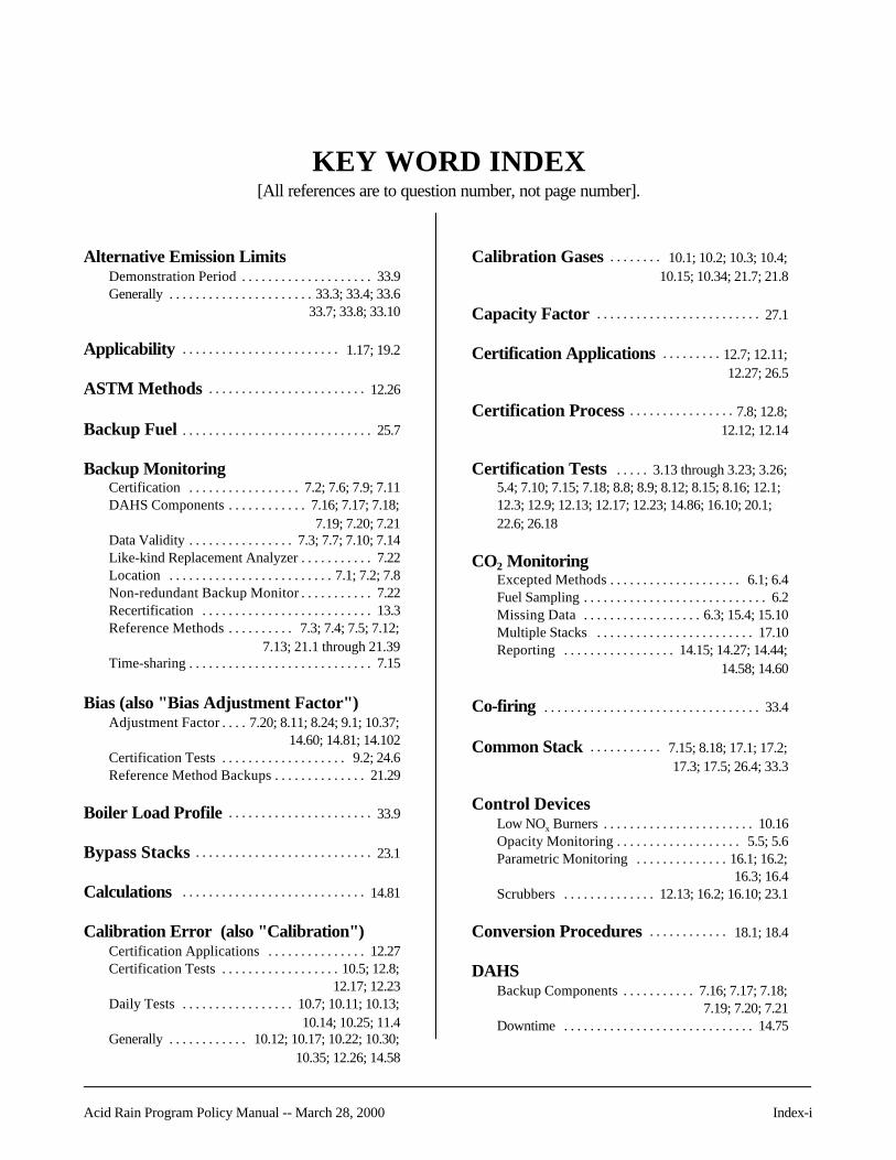
Acid Rain Program Policy Manual -- March 28, 2000 Index-i
KEY WORD INDEX[All references are to question number, not page number].
Alternative Emission LimitsDemonstration Period . . . . . . . . . . . . . . . . . . . . 33.9Generally . . . . . . . . . . . . . . . . . . . . . . 33.3; 33.4; 33.6
33.7; 33.8; 33.10
Applicability . . . . . . . . . . . . . . . . . . . . . . . . 1.17; 19.2
ASTM Methods . . . . . . . . . . . . . . . . . . . . . . . . 12.26
Backup Fuel . . . . . . . . . . . . . . . . . . . . . . . . . . . . . 25.7
Backup MonitoringCertification . . . . . . . . . . . . . . . . . 7.2; 7.6; 7.9; 7.11DAHS Components . . . . . . . . . . . . 7.16; 7.17; 7.18;
7.19; 7.20; 7.21Data Validity . . . . . . . . . . . . . . . . 7.3; 7.7; 7.10; 7.14Like-kind Replacement Analyzer . . . . . . . . . . . 7.22Location . . . . . . . . . . . . . . . . . . . . . . . . . 7.1; 7.2; 7.8Non-redundant Backup Monitor . . . . . . . . . . . 7.22Recertification . . . . . . . . . . . . . . . . . . . . . . . . . . 13.3Reference Methods . . . . . . . . . . 7.3; 7.4; 7.5; 7.12;
7.13; 21.1 through 21.39Time-sharing . . . . . . . . . . . . . . . . . . . . . . . . . . . . 7.15
Bias (also "Bias Adjustment Factor")Adjustment Factor . . . . 7.20; 8.11; 8.24; 9.1; 10.37;
14.60; 14.81; 14.102Certification Tests . . . . . . . . . . . . . . . . . . . 9.2; 24.6Reference Method Backups . . . . . . . . . . . . . . 21.29
Boiler Load Profile . . . . . . . . . . . . . . . . . . . . . . 33.9
Bypass Stacks . . . . . . . . . . . . . . . . . . . . . . . . . . . 23.1
Calculations . . . . . . . . . . . . . . . . . . . . . . . . . . . . 14.81
Calibration Error (also "Calibration")Certification Applications . . . . . . . . . . . . . . . 12.27Certification Tests . . . . . . . . . . . . . . . . . . 10.5; 12.8;
12.17; 12.23Daily Tests . . . . . . . . . . . . . . . . . 10.7; 10.11; 10.13;
10.14; 10.25; 11.4Generally . . . . . . . . . . . . 10.12; 10.17; 10.22; 10.30;
10.35; 12.26; 14.58
Calibration Gases . . . . . . . . 10.1; 10.2; 10.3; 10.4;10.15; 10.34; 21.7; 21.8
Capacity Factor . . . . . . . . . . . . . . . . . . . . . . . . . 27.1
Certification Applications . . . . . . . . . 12.7; 12.11;12.27; 26.5
Certification Process . . . . . . . . . . . . . . . . 7.8; 12.8;12.12; 12.14
Certification Tests . . . . . 3.13 through 3.23; 3.26;5.4; 7.10; 7.15; 7.18; 8.8; 8.9; 8.12; 8.15; 8.16; 12.1;12.3; 12.9; 12.13; 12.17; 12.23; 14.86; 16.10; 20.1;22.6; 26.18
CO2 MonitoringExcepted Methods . . . . . . . . . . . . . . . . . . . . 6.1; 6.4Fuel Sampling . . . . . . . . . . . . . . . . . . . . . . . . . . . . 6.2Missing Data . . . . . . . . . . . . . . . . . . 6.3; 15.4; 15.10Multiple Stacks . . . . . . . . . . . . . . . . . . . . . . . . 17.10Reporting . . . . . . . . . . . . . . . . . 14.15; 14.27; 14.44;
14.58; 14.60
Co-firing . . . . . . . . . . . . . . . . . . . . . . . . . . . . . . . . . 33.4
Common Stack . . . . . . . . . . . 7.15; 8.18; 17.1; 17.2;17.3; 17.5; 26.4; 33.3
Control DevicesLow NOx Burners . . . . . . . . . . . . . . . . . . . . . . . 10.16Opacity Monitoring . . . . . . . . . . . . . . . . . . . 5.5; 5.6Parametric Monitoring . . . . . . . . . . . . . . 16.1; 16.2;
16.3; 16.4Scrubbers . . . . . . . . . . . . . . 12.13; 16.2; 16.10; 23.1
Conversion Procedures . . . . . . . . . . . . 18.1; 18.4
DAHSBackup Components . . . . . . . . . . . 7.16; 7.17; 7.18;
7.19; 7.20; 7.21Downtime . . . . . . . . . . . . . . . . . . . . . . . . . . . . . 14.75

Key Word Index
Index-ii Acid Rain Program Policy Manual -- March 28, 2000
DAHS (cont.)General . . . . . . . . . . . . . . . . 13.5; 13.6; 14.12; 14.72;
14.73; 15.3; 25.6Verification . . . . . . . . . . . . 14.8; 14.87; 14.96; 21.33
DCAS . . . . . . . . . . . . . . . . . . . . . . . . . . . . . 14.85; 14.86
Data Reduction . . . . . . . . . . . . . . . . . . . 14.37; 14.51;14.53; 21.19; 21.28
Data ValidityBackup Monitoring . . . . . . . . . . . . . . . . . . . 7.3; 7.7;
7.10; 21.19Calibration Tests . . . . . . . . . . . . . . . . . 10.26; 15.24NOx Monitoring . . . . . . . . . . . . . . . . . . . . . 4.2; 7.10Hourly Requirements . . . . . . . . . . . . . ..15.1; 15.30Reporting . . . . . . . . . . . . . . . . . . . . . . . 14.21; 25.12
DeadlinesCertification . . . . . . . . . . . . . . . . . . . . . . 12.7; 12.11Linearity Tests . . . . . . . . . . . . . . . . . . . 10.24; 15.26Quarterly Reporting . . . . . . . . . . . . . . . . . . . . . . 14.2RATAs . . . . . . . . . . . . . . . . . . . 8.2; 8.20; 8.21; 8.28
Default High Range . . . . . . . . . . . . . . . . . . . . 10.29
Designated Representative . . . . . . . . . . . . 14.38
Diagnostic Testing . . . . . . . . . . . . . 3.12; 3.13; 3.143.15; 3.16; 3.19; 3.20; 3.21; 3.22; 3.23; 3.26;
13.5; 13.13; 13.15; 13.16; 13.17; 13.18
Differential Pressure Flow Monitors . . . . . . . . . . . . . . . . . . . . . . . . . . 10.5
Diluent Cap . . . . . . . . . . . . . . . . . . . . . . . . . . . . . . . 6.5
Diluent Monitors . . . . . . . . . . . . . . 6.4; 10.15; 14.3914.40; 14.41; 15.28
Dual-range Monitors . . . . . . . . . . 8.4; 10.6; 10.16;10.21; 10.28; 10.29
Electronic Data Reporting . . . . 1.11; 1.12; 14.80
Electronic Report FormatsCO2 Reporting . . . . . . . . . . . . . . 14.44; 14.58; 14.60Diagnostic Tests . . . . . . . . . . . . . . . . . . . . . . . 13.17Generally . . . . . . . . . 1.12; 14.4; 14.37; 14.38; 14.51;
14.52; 14.90; 14.92; 14.93; 14.94; 14.95;14.97; 14.98; 22.11; 24.7; 24.8; 24.11
Missing Data . . . . . . . . . . . . . . . . . . . . . 14.7; 15.17Moisture . . . . . . . . . . . . . . . . . . . . . . . . . 14.99; 28.1Reference Method Backups . . . . . . . . 21.21; 21.22;
21.34; 21.35; 21.39RT Series 100 . . . . . . . . . . . . . . . . . . . 14.20B; 14.24RT Series 200 (Only) . . . . . . . . . . . . . . 14.19; 14.27;
21.34; 21.39RT Series 300 (Only) . . . . . . . . . . . 14.20A; 14.20B;
14.21; 14.47; 14.49; 15.10; 17.7; 17.10;17.11; 17.12; 17.14; 22.9; 24.9; 25.10
RT Series 200/300 (Both) . . . . . . . . . . 14.15; 14.1614.26; 14.36; 17.6;17.9; 21.22; 21.35
RT Series 500 . . . . . . . . . . . 7.21; 13.7; 13.8; 14.30;14.31; 14.62; 14.63; 14.64; 14.65;
14.66; 14.69; 14.88; 22.5RT Series 600 . . . . . . . . . . . . . . . . 8.16; 14.17, 14.89
Enforcement . . . . . . . . . . . . . . . . . . . . . . . . . . . . . 20.3
EPA Approvals . . . . . . . . . . . . . . . . . . . . . . . . . . 12.7
Excepted MethodsAppendix D . . . . . . . . . . . . . . . . . . 3.2; 10.12; 10.17;
12.14; 12.18;12.19; 12.23; 12.27; 14.49;14.72; 14.73; 15.9; 15.12; 15.17; 15.20;
15.21;15.22; 15.23; 18.5;25.1 through 25.11; 25.13; 25.14; 25.15
Appendix E . . . . . . . . . . . . . . . . 10.17; 12.14; 12.18;12.19; 12.27; 13.20; 14.46; 14.47; 14.48;
14.72; 14.73; 15.12; 15.19; 25.1;26.1 through 26.19
Appendix G . . . . . . . . . . . . . . . . . . . 6.1; 15.10; 17.10
ExemptionsNew Units . . . . . . . . . . . . . . . . . . . . . . . . . . . . . . 19.1Opacity Monitoring . . . . . . . . . . . . . . . . . . . . . . . 5.6
F-factors . . . . . . . . . . . . . . . . . . 18.1; 18.5; 18.6; 26.14
Flow-to-load Test . . . . . . . . . . . . . . 3.24; 3.25; 8.27;10.26; 11.3; 25.12
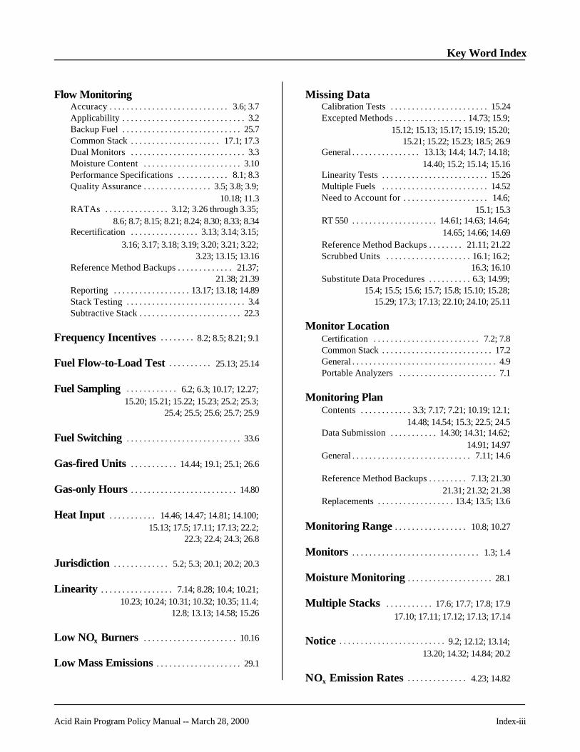
Key Word Index
Acid Rain Program Policy Manual -- March 28, 2000 Index-iii
Flow MonitoringAccuracy . . . . . . . . . . . . . . . . . . . . . . . . . . . . 3.6; 3.7Applicability . . . . . . . . . . . . . . . . . . . . . . . . . . . . . 3.2Backup Fuel . . . . . . . . . . . . . . . . . . . . . . . . . . . . 25.7Common Stack . . . . . . . . . . . . . . . . . . . . . 17.1; 17.3Dual Monitors . . . . . . . . . . . . . . . . . . . . . . . . . . . 3.3Moisture Content . . . . . . . . . . . . . . . . . . . . . . . 3.10Performance Specifications . . . . . . . . . . . . 8.1; 8.3Quality Assurance . . . . . . . . . . . . . . . . 3.5; 3.8; 3.9;
10.18; 11.3RATAs . . . . . . . . . . . . . . . 3.12; 3.26 through 3.35;
8.6; 8.7; 8.15; 8.21; 8.24; 8.30; 8.33; 8.34Recertification . . . . . . . . . . . . . . . . 3.13; 3.14; 3.15;
3.16; 3.17; 3.18; 3.19; 3.20; 3.21; 3.22;3.23; 13.15; 13.16
Reference Method Backups . . . . . . . . . . . . . 21.37;21.38; 21.39
Reporting . . . . . . . . . . . . . . . . . . 13.17; 13.18; 14.89Stack Testing . . . . . . . . . . . . . . . . . . . . . . . . . . . . 3.4Subtractive Stack . . . . . . . . . . . . . . . . . . . . . . . . 22.3
Frequency Incentives . . . . . . . . 8.2; 8.5; 8.21; 9.1
Fuel Flow-to-Load Test . . . . . . . . . . 25.13; 25.14
Fuel Sampling . . . . . . . . . . . . 6.2; 6.3; 10.17; 12.27;15.20; 15.21; 15.22; 15.23; 25.2; 25.3;
25.4; 25.5; 25.6; 25.7; 25.9
Fuel Switching . . . . . . . . . . . . . . . . . . . . . . . . . . . 33.6
Gas-fired Units . . . . . . . . . . . 14.44; 19.1; 25.1; 26.6
Gas-only Hours . . . . . . . . . . . . . . . . . . . . . . . . . 14.80
Heat Input . . . . . . . . . . . 14.46; 14.47; 14.81; 14.100;15.13; 17.5; 17.11; 17.13; 22.2;
22.3; 22.4; 24.3; 26.8
Jurisdiction . . . . . . . . . . . . . 5.2; 5.3; 20.1; 20.2; 20.3
Linearity . . . . . . . . . . . . . . . . . 7.14; 8.28; 10.4; 10.21;10.23; 10.24; 10.31; 10.32; 10.35; 11.4;
12.8; 13.13; 14.58; 15.26
Low NOx Burners . . . . . . . . . . . . . . . . . . . . . . 10.16
Low Mass Emissions . . . . . . . . . . . . . . . . . . . . 29.1
Missing DataCalibration Tests . . . . . . . . . . . . . . . . . . . . . . . 15.24Excepted Methods . . . . . . . . . . . . . . . . . 14.73; 15.9;
15.12; 15.13; 15.17; 15.19; 15.20;15.21; 15.22; 15.23; 18.5; 26.9
General . . . . . . . . . . . . . . . . 13.13; 14.4; 14.7; 14.18;14.40; 15.2; 15.14; 15.16
Linearity Tests . . . . . . . . . . . . . . . . . . . . . . . . . 15.26Multiple Fuels . . . . . . . . . . . . . . . . . . . . . . . . . 14.52Need to Account for . . . . . . . . . . . . . . . . . . . . 14.6;
15.1; 15.3RT 550 . . . . . . . . . . . . . . . . . . . . 14.61; 14.63; 14.64;
14.65; 14.66; 14.69Reference Method Backups . . . . . . . . 21.11; 21.22Scrubbed Units . . . . . . . . . . . . . . . . . . . . 16.1; 16.2;
16.3; 16.10Substitute Data Procedures . . . . . . . . . . 6.3; 14.99;
15.4; 15.5; 15.6; 15.7; 15.8; 15.10; 15.28;15.29; 17.3; 17.13; 22.10; 24.10; 25.11
Monitor LocationCertification . . . . . . . . . . . . . . . . . . . . . . . . . 7.2; 7.8Common Stack . . . . . . . . . . . . . . . . . . . . . . . . . . 17.2General . . . . . . . . . . . . . . . . . . . . . . . . . . . . . . . . . . 4.9Portable Analyzers . . . . . . . . . . . . . . . . . . . . . . . 7.1
Monitoring PlanContents . . . . . . . . . . . . 3.3; 7.17; 7.21; 10.19; 12.1;
14.48; 14.54; 15.3; 22.5; 24.5Data Submission . . . . . . . . . . . 14.30; 14.31; 14.62;
14.91; 14.97General . . . . . . . . . . . . . . . . . . . . . . . . . . . . 7.11; 14.6
Reference Method Backups . . . . . . . . . 7.13; 21.3021.31; 21.32; 21.38
Replacements . . . . . . . . . . . . . . . . . . 13.4; 13.5; 13.6
Monitoring Range . . . . . . . . . . . . . . . . . 10.8; 10.27
Monitors . . . . . . . . . . . . . . . . . . . . . . . . . . . . . . 1.3; 1.4
Moisture Monitoring . . . . . . . . . . . . . . . . . . . . 28.1
Multiple Stacks . . . . . . . . . . . 17.6; 17.7; 17.8; 17.917.10; 17.11; 17.12; 17.13; 17.14
Notice . . . . . . . . . . . . . . . . . . . . . . . . . 9.2; 12.12; 13.14;13.20; 14.32; 14.84; 20.2
NOx Emission Rates . . . . . . . . . . . . . . 4.23; 14.82

Key Word Index
Index-iv Acid Rain Program Policy Manual -- March 28, 2000
NOx MonitoringCertification Process . . . . . . . . . . . . . . . . . . . . 15.12Data Validity . . . . . . . . . . . . . . . . . . . . . . . . . . . . . 4.2Dual-range Monitors . . . . . . . . . . . . . . . . . . . . . 10.6Excepted Methods . . . . . . . . . . . . . . . . 12.18; 12.19;
14.46; 14.48; 15.12; 15.19;18.5; 26.1 through 26.18
General . . . . . . . . . . . . . . . . . . . . . . . . . . . . . . . . . . 4.9Low Emitters . . . . . . . . . . . . . . . . . . . . . . . . . . . . 8.19Maximum Potential Concentration . . . . . . . . . . . . . . . . . . . 10.19; 10.36Multiple Stacks . . . . . . . . . . . . . . . . . . . . 17.6; 17.7;
17.8; 17.13NOx Apportionment . . . . . . . . . . . . 24.1; 24.2; 24.4
24.9; 24.11; 24.12; 24.13Reference Method Backups . . . . . . . . . . . . . . . 21.5Reports/Recordkeeping . . . . . . . . . . . . . . . . . 14.16Span . . . . . . . . . . . . . . . . . . . . . . . . . . . . . . . . . . 10.10Subtractive Stack . . . . . . . . . . . . . . . . . . . 22.1; 22.3
Oil-fired UnitsDiesel-fired units . . . . . . . . . . . . . . . . . . . . . . . . 19.2Exemptions . . . . . . . . . . . . . . . . . . . . . . . . . . . . . 19.1Fuel Flow . . . . . . . . . . . . . . . . . . . . . . . . . . . . . . 10.12Fuel Sampling . . . . . . . . . . . . . . . . . . . . . . 25.3; 25.5
Opacity MonitoringGeneral . . . . . . . . . . . . . . . . . . . . . . . . . . . 5.2; 5.5; 5.6Performance Specifications . . . . . . . . . . . 5.4; 12.3Reporting/Records . . . . . . . . . . . . . . . . 5.1; 5.2; 5.3
Operational Problems . . . . . . . . . . . . . . . . . . . 33.7
Parametric Procedures . . . . . . . . . . . . . . . . . . 16.4
Peaking Units . . . . . . . . . . . . . . . . . . . . . . . 3.25; 8.26
Petitions . . . . . . . . . . . . . . . . . . . . . . . . 1.3; 12.26; 18.6
Portable Monitoring . . . . . . . . . . . . . . . . . . . . . 13.1
Predictive Emissions Monitoring Systems . . . . . . . . . . . . . . . . . . . . . . . . . . . . . . . . 1.15
Quality Assurance (also "QA/QC")Backup Monitoring . . . . . . . . . . . . 7.15; 7.18; 21.9;
21.10; 21.11; 21.12; 21.13; 21.14;21.15; 21.23; 21.25; 21.26; 21.27
Failed Tests . . . . . . . . . . . . . . . . . . . . . . . . . . . . 15.2Flow . . . . . . . . . . . . . . . . . . 3.5; 3.8; 3.9; 10.18; 11.3
Quality Assurance (cont.)General . . . . . . . . . 1.16; 7.11; 10.11; 14.2; 22.6; 24.6Plan . . . . . . . . . . . . . . . . . . . . . . . . . . 11.1; 11.2; 11.6
Range . . . . . . . . . . . . . . . . . . . . . . . . . . . . . . . . . . . 10.37
RATAsBias . . . . . . . . . . . . . . . . . . . . . . . . . . . . 8.24; 14.102Common Stack . . . . . . . . . . . . . . . . . . . . . 8.18; 17.1Dual-range Monitors . . . . . . . . . . . . . . . . . . . . . . 8.4Flow Monitors . . . . . . . . . . . . . . . 3.12; 13.15; 13.16Frequency . . . . . . . . . . . . . . . . . . . . . . . . . . . 8.2; 8.5
8.17; 8.19; 9.1Missed Deadline . . . . . . . . . . . . . . . . . . . . . . . 15.26Notice . . . . . . . . . . . . . . . . . . . . . . . . . . . . . . . . 14.84Out-of-control Periods . . . . . . . . . . . . . . . . . . . 15.2Reference Methods . . . . . . . . . . . . . . . . . . . 7.5; 8.6;
8.7; 8.29Reporting . . . . . . . . . . . . . . . . . . 8.16; 14.17; 14.32;
14.33; 14.100Scheduling . . . . . . . . . . . . . . . . . . . . 8.20; 8.21; 8.28Test Procedures . . . . . . . . . 8.3; 8.8; 8.9; 8.11; 8.12
8.15; 8.27; 10.35; 11.3;11.4; 12.8; 21.2; 21.4
Wet Scrubbers . . . . . . . . . . . . . . . . . . . . . . . . . . 8.25
RecertificationBackup/Portable Monitors . . . . . . . . 7.4; 13.1; 13.3Changes Requiring Recertification . . . . 13.2; 13.4;
13.5; 13.6; 13.15;13.16; 13.19; 26.18
Generally . . . . . . . . . . . . . . . . 3.13; 3.14; 3.15; 3.16;3.17; 3.18; 3.19; 3.20; 3.21;
3.22; 3.23; 3.26; 13.12Reporting . . . . . . . . . . . . . . . . . . . . . . . . 13.8; 13.14Stored Data . . . . . . . . . . . . . . . . . . . . . . . . . . . . 14.75Test Requirements . . . . . . . . . . . . . . . . . . . . . . 13.13and see Certification
RecordkeepingGeneral . . . . . . . . . . . . . . . . . 14.3; 14.6; 14.18; 14.89Hourly Records . . . . . . . . . . . . . . . . . . . . 14.4; 14.5Opacity . . . . . . . . . . . . . . . . . . . . . . . . . . . . . . . . . 5.3Parametric Data . . . . . . . . . . . . . . . . . . . . . . . . . 16.3Quality Assurance . . . . . . . . . . . . . . 8.35; 11.1; 11.2Reference Method Backups . . . . . . . . . . . . . . 21.36
Reference Methods . . . . . . . . . 3.4; 3.6; 3.7; 3.10;7.1; 7.3; 7.4; 7.5; 7.12; 7.13; 8.6; 8.7;
8.12; 8.22; 8.23; 8.25; 8.29; 13.1;13.3; 21.1 through 21.39

Key Word Index
Acid Rain Program Policy Manual -- March 28, 2000 Index-v
Relative Accuracy . . . . . . . . . . . 3.13 through 3.23;3.26 through 3.35; 8.1;
8.30; 8.31; 8.32; 8.35
ReportingDaily Calibration Tests . . . . . . . . . . . . . 10.7; 10.11;
10.13; 10.18; 10.25Determination Codes . . . . . . . . . . . . . . . . . . . 14.15;
14.16; 14.18; 15.8Diluent Monitors . . . . . . . . . . . . 14.39; 14.40; 14.41Excepted Methods . . . . . . . . . . . . . . . . 14.46; 14.49Flow . . . . . . . . . . . . . . . . . . . . . . . . 3.3; 3.5; 3.8; 3.9;
13.18; 21.39; 25.11Fuel Usage . . . . . . . . . . . . . . . . . . . . . . . . . . . . 14.53Gas-only Hours . . . . . . . . . . . . . . . . . . . . . . . . . . 2.6Generally . . . . . . . . . . . . . . 1.12; 7.19; 10.27; 10.28;
14.19; 14.51; 14.88; 14.97;14.98; 16.10; 20.2
Hourly Data . . . . . . . . . . . . . . . . . . . . . . . . 2.6; 14.5;14.21; 14.36; 14.101
Linearity . . . . . . . . . . . . . . . . . . . . . . . . . . . . . . 10.32Load . . . . . . . . . . . . . . . . . . . . . . . . . . . . . . . . . . . 18.4Missing Data . . . . . . . . . . . . . . . . . . . . . . 13.7; 14.7;
14.26; 14.61; 14.63; 14.64; 14.65;14.66;14.69; 15.10
Multiple Stacks . . . . . . . . . . . . . . . 17.6; 17.7; 17.9;17.10; 17.11; 17.12
NOx Emission Rates . . . . . . . . . . . . . . . . . . . . 14.82;26.15; 26.16
Opacity . . . . . . . . . . . . . . . . . . . . . . . . . . . . . 5.1; 5.2Quarterly Reports . . . . . . . . . . . . . . . . . 14.2; 14.17;
14.20A; 14.20B; 14.24;14.30; 14.38; 14.54
RATA Results . . . . . . . . . . . . . . . . 8.16; 8.17; 8.26;14.33; 14.100; 14.102
Recertification . . . . . . . . . . . . . . . . . . . . 13.8; 13.19Reference Method Backups . . . . . . . . . 7.12; 21.21;
21.22; 21.34; 21.35; 21.39Span Changes . . . . . . . . . . . . . . . . . . . . 10.8; 10.29Startup . . . . . . . . . . . . . . . . . . . . . . . . . . . . . . . . 14.27Subtractive Stack . . . . . . . . . . . . . . 22.7; 22.8; 22.10and see Electronic Report Formats
Sampling Location . . . . . . . . . . . . . . . . . . . . . . 21.16
Scrubbers . . . . . . . . . . . . . . . . . . . . . . . . . . . . . . . . 8.25
SO2 MonitoringBackup Fuel . . . . . . . . . . . . . . . . . . . . . . . . . . . 25.10Bypass Stack Provisions . . . . . . . . . . . . . . . . . 23.1Certification . . . . . . . . . . . . . . . . . . . . . . . . . . . 15.12
SO2 Monitoring (cont.)Excepted Methods . . . . . . . . . . . . . . . . 12.18; 12.19;
15.9; 15.12; 15.17; 25.1 through 25.7; 25.10; 25.11; 26.6
Generally . . . . . . . . . . . . . . . . . . . . . . . . . . . . . . . . 2.6Maximum Potential Concentration . . . . . . . . . . . . . . . . . . . . . . . . . 10.19Multiple Stacks . . . . . . . . . . . . . . . . . . . . . . . . . 17.9Performance Specifications . . . . . . . . . . . . . . . 8.1;
8.3; 10.10Reporting . . . . . . . . . . . . . . . 2.6; 2.16; 14.80; 14.88Subtractive Stack . . . . . . . . . . . . . . . . . . . . . . . . 22.2
Span . . . . . . . . . . . . . . . . . . . . . . . . . . . 10.1; 10.8; 10.10;10.15;10.19; 10.31; 10.33; 21.6
Stack Testing . . . . . . . . . . . . . . . . . . . . . . . . . . . . 26.3
Time-sharing . . . . . . . . . . . . . . . . . . . . . . . . 1.2; 7.15
Vendor Guarantees . . . . . . . . . . . . . . . . . . . . . 33.8
Wall Effects Adjustment Factor . . . . . . . 3.27;3.28; 3.31 through 3.35

Key Word Index
Index-vi Acid Rain Program Policy Manual -- March 28, 2000
[This page intentionally left blank]

Acid Rain Program Policy Manual -- March 28, 2000 Page A-1
APPENDIX A: EPA REGIONAL/STATE ACIDRAIN CEM CONTACT LIST
REGION I CEM CONTACTS
EPA Headquarters ContactMs. Theresa Alexander . . . . . . . . . . . . . . . . . . . . . . . . . . . . . . . . . . . . . . . . . . . . . . . . (202) 564-9747Ariel Rios Building Fax (202) 565-21411200 Pennsylvania Avenue, NW (6204J) E-mail: [email protected], D.C. 20460
EPA Regional Office ContactsMr. Alan Hicks . . . . . . . . . . . . . . . . . . . . . . . . . . . . . . . . . . . . . . . . . . . . . . . . . . . . . . (781) 860-4388US EPA, New England Regional Lab Fax (781) 860-4397O.E.M.E. E-mail: [email protected] Westview StreetLexington, Massachusetts 02421
Mr. Ian Cohen . . . . . . . . . . . . . . . . . . . . . . . . . . . . . . . . . . . . . . . . . . . . . . . . . . . . . . . (617) 918-1655US EPA, Region I Fax (617) 918-1505One Congress Street, Suite 1100 E-mail: [email protected] Stop CAPBoston, Massachusetts 02114-2023
Connecticut DEP ContactMr. Keith Hill (primary) . . . . . . . . . . . . . . . . . . . . . . . . . . . . . . . . . . . . . . . . . . . . . . . . (860) 424-3563Department of Environmental Protection Fax (860) 424-4179Bureau of Air Management E-mail: [email protected] Elm Street, 6th Floor AnnexHartford, Connecticut 06106-5127
Mr. Stephen Anderson . . . . . . . . . . . . . . . . . . . . . . . . . . . . . . . . . . . . . . . . . . . . . . . . . (860) 424-3453Department of Environmental Protection Fax (860) 424-4064Bureau of Air Management E-mail: [email protected] Elm Street, 6th Floor AnnexHartford, Connecticut 06106-5127

Regional/State CEM Contact List Appendix A
Page A-2 Acid Rain Program Policy Manual -- March 28, 2000
Vermont ANR ContactMr. Robert Lacaillade . . . . . . . . . . . . . . . . . . . . . . . . . . . . . . . . . . . . . . . . . . . . . . . . . (802) 241-3852Division of Environmental Conservation Fax (802) 241-2590Air Pollution Control Department E-mail: [email protected] 3 South103 South Main StreetWaterbury, Vermont 05671-0402
New Hampshire ESA ContactMr. Raymond Walters (primary) . . . . . . . . . . . . . . . . . . . . . . . . . . . . . . . . . . . . . . . . . . (603) 271-6288New Hampshire Department of Fax (603) 271-1381 Environmental Services E-mail: [email protected] Resources Division64 North Main StreetP.O. Box 203Concord, New Hampshire 03302-2033
Mr. Jack Glenn . . . . . . . . . . . . . . . . . . . . . . . . . . . . . . . . . . . . . . . . . . . . . . . . . . . . . . (603) 271-6546New Hampshire Department of Fax (603) 271-1381 Environmental Services E-mail: [email protected] Resources Division64 North Main Street P.O. Box 2033Concord, New Hampshire 03302-2033
Massachusetts DEP ContactMs. Sharon Weber. . . . . . . . . . . . . . . . . . . . . . . . . . . . . . . . . . . . . . . . . . . . . (978) 975-1138, ext. 343Department of Environmental Protection Fax (978) 688-0352Bureau of Waste Prevention E-mail: [email protected] Shattuck StreetLawrence, Massachusetts 01843-1398
Ms. Karen Regas . . . . . . . . . . . . . . . . . . . . . . . . . . . . . . . . . . . . . . . . . . . . . . . . . . . . . (617) 292-5624Department of Environmental Protection Fax (617) 292-5778Business Compliance Division Email: [email protected] Winter StreetBoston, Massachusetts 02108

Appendix A Regional/State CEM Contact List
Acid Rain Program Policy Manual -- March 28, 2000 Page A-3
Rhode Island DEM ContactMr. Terry Tuchon . . . . . . . . . . . . . . . . . . . . . . . . . . . . . . . . . . . . . . . . . . . . . (401) 222-2808, ext. 7024RI Department of Environmental Management Fax (401) 222-2017Office of Air Resources E-mail: [email protected] Promonade StreetProvidence, Rhode Island 02908
Maine DEP ContactMr. Bob Hartley . . . . . . . . . . . . . . . . . . . . . . . . . . . . . . . . . . . . . . . . . . . . . . . . . . . . . . (207) 287-2437Department of Environmental Protection Fax (207) 287-7641Bureau of Air Quality E-mail: [email protected] Statehouse StationAugusta, Maine 04333-0017
REGION II CEM CONTACTS
EPA Headquarters ContactMr. George Croll . . . . . . . . . . . . . . . . . . . . . . . . . . . . . . . . . . . . . . . . . . . . . . . . . . . . . (202) 564-0162Ariel Rios Building Fax (202) 565-21411200 Pennsylvania Avenue, NW (6204J) E-mail: [email protected], D.C. 20460
EPA Regional Office ContactMs. Ann Zownir . . . . . . . . . . . . . . . . . . . . . . . . . . . . . . . . . . . . . . . . . . . . . . . . . . . . . . . (732 321-6699US EPA, Region II Fax(732)321-6616Monitoring and Assessment Branch [email protected] Woodbridge AvenueEdison, New Jersey 08837-3679
New York DEC ContactMr. Dennis Sullivan . . . . . . . . . . . . . . . . . . . . . . . . . . . . . . . . . . . . . . . . . . . . . . . . . . . (518) 457-7689New York State Division Fax (518) 458-8427 of Environmental Conservation [email protected] of Air ResourcesBureau of Compliance Monitoring & Enforcement50 Wolf Road, Room 108Albany, New York 12233-3258
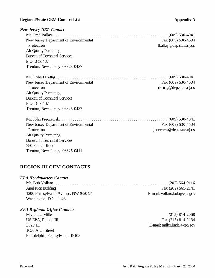
Regional/State CEM Contact List Appendix A
Page A-4 Acid Rain Program Policy Manual -- March 28, 2000
New Jersey DEP ContactMr. Fred Ballay . . . . . . . . . . . . . . . . . . . . . . . . . . . . . . . . . . . . . . . . . . . . . . . . . . . . . . (609) 530-4041New Jersey Department of Environmental Fax (609) 530-4504 Protection [email protected] Quality Permitting Bureau of Technical ServicesP.O. Box 437Trenton, New Jersey 08625-0437
Mr. Robert Kettig . . . . . . . . . . . . . . . . . . . . . . . . . . . . . . . . . . . . . . . . . . . . . . . . . . . . (609) 530-4041New Jersey Department of Environmental Fax (609) 530-4504 Protection [email protected] Quality Permitting Bureau of Technical ServicesP.O. Box 437Trenton, New Jersey 08625-0437
Mr. John Preczewski . . . . . . . . . . . . . . . . . . . . . . . . . . . . . . . . . . . . . . . . . . . . . . . . . . (609) 530-4041New Jersey Department of Environmental Fax (609) 530-4504 Protection [email protected] Quality Permitting Bureau of Technical Services380 Scotch RoadTrenton, New Jersey 08625-0411
REGION III CEM CONTACTS
EPA Headquarters ContactMr. Bob Vollaro . . . . . . . . . . . . . . . . . . . . . . . . . . . . . . . . . . . . . . . . . . . . . . . . . . . . . (202) 564-9116Ariel Rios Building Fax (202) 565-21411200 Pennsylvania Avenue, NW (6204J) E-mail: [email protected], D.C. 20460
EPA Regional Office ContactsMs. Linda Miller (215) 814-2068US EPA, Region III Fax (215) 814-21343 AP 11 E-mail: [email protected] Arch StreetPhiladelphia, Pennsylvania 19103

Appendix A Regional/State CEM Contact List
Acid Rain Program Policy Manual -- March 28, 2000 Page A-5
Delaware DNREC ContactMr. Mark Lutrzykowski (primary) . . . . . . . . . . . . . . . . . . . . . . . . . . . . . . . . . . . . . . . . (302) 323-4542Department of Natural Resources Fax (302) 323-4598 and Environmental Control E-mail: [email protected] and Waste Management Division715 Grantham LaneNew Castle, Delaware 19720
Mr. Jeff Rogers . . . . . . . . . . . . . . . . . . . . . . . . . . . . . . . . . . . . . . . . . . . . . . . . . . . . . . (302) 323-4542Department of Natural Resources Fax (302) 323-4598 and Environmental Control E-mail: [email protected] and Waste Management Division715 Grantham LaneNew Castle, Delaware 19720
District of Columbia ARMD ContactMr. Rudolph Schreiber . . . . . . . . . . . . . . . . . . . . . . . . . . . . . . . . . . . . . . . . . (202) 645-6093, ext. 3003D.C. Department of Health Fax (202) 645-6102Environmental Health Administration E-mail: [email protected] Quality Division2100 Martin Luther King, Jr. Ave., S.E.Washington, D.C. 20020-5732
Mr. Stan Tracey . . . . . . . . . . . . . . . . . . . . . . . . . . . . . . . . . . . . . . . . . . . . . (202) 645-6093, ext. 3063D.C. Department of Health Fax (202) 645-6102Environmental Health Administration E-mail: [email protected] Quality Division2100 Martin Luther King, Jr. Ave., S.E.Washington, D.C. 20020-5732
Maryland ARMA ContactMr. Parsuram Ramnarain . . . . . . . . . . . . . . . . . . . . . . . . . . . . . . . . . . . . . . . . . . . . . . . (410) 631-4483Air and Radiation Management Administration Fax (410) 631-3202Air Quality Compliance Program E-mail: [email protected] Broening HighwayBaltimore, Maryland 21224
Mr. Charles Frushour . . . . . . . . . . . . . . . . . . . . . . . . . . . . . . . . . . . . . . . . . . . . . . . . . . (410) 631-4483Air and Radiation Management Administration Fax (410) 631-3202Air Quality Compliance Program E-mail: [email protected] Broening HighwayBaltimore, Maryland 21224

Regional/State CEM Contact List Appendix A
Page A-6 Acid Rain Program Policy Manual -- March 28, 2000
West Virginia OAQ ContactMr. Earl Billingsley . . . . . . . . . . . . . . . . . . . . . . . . . . . . . . . . . . . . . . . . . . . . . . . . . . . . (304) 558-4022Department of Environmental Protection Fax (304) 558-3287Office of Air Quality Email: [email protected] Washington Street East Charleston, West Virginia 25311
Ms. Laura Crowder . . . . . . . . . . . . . . . . . . . . . . . . . . . . . . . . . . . . . . . . . . . . . . . . . . . (304) 558-4022Department of Environmental Protection Fax (304) 558-3287Office of Air Quality Email: [email protected] Washington Street East Charleston, West Virginia 25311
Pennsylvania DER/Local ContactsMr. Joseph Nazzaro, Chief . . . . . . . . . . . . . . . . . . . . . . . . . . . . . . . . . . . . . . . . . . . . . . (717) 783-9247Pennsylvania Department of Fax (717) 772-2303 Environmental Resources E-mail: [email protected] Market Street, 12th FloorP.O. Box 8468Harrisburg, Pennsylvania 17105-8468
Mr. Rick Begley . . . . . . . . . . . . . . . . . . . . . . . . . . . . . . . . . . . . . . . . . . . . . . . . . . . . . . (717) 783-9249Pennsylvania Department of Fax (717) 772-2303 Environmental Resources E-mail: [email protected] Market Street, 12th FloorP.O. Box 8468Harrisburg, Pennsylvania 17105-8468
Mr. John Pitulski . . . . . . . . . . . . . . . . . . . . . . . . . . . . . . . . . . . . . . . . . . . . . . . . . . . . . (717) 783-9468Pennsylvania Department of Fax (717) 772-2303 Environmental Resources E-mail: [email protected] Market Street, 12th FloorP.O. Box 8468Harrisburg, Pennsylvania 17105-8468
Allegheny CountyMr. Edward Taylor . . . . . . . . . . . . . . . . . . . . . . . . . . . . . . . . . . . . . . . . . . . . . . . . . . . (412) 578-8138Allegheny County Health Department Fax (412) 578-8144Air Quality Program301 39th StreetPittsburgh, Pennsylvania 15201

Appendix A Regional/State CEM Contact List
Acid Rain Program Policy Manual -- March 28, 2000 Page A-7
PhiladelphiaMr. Frank Steitz . . . . . . . . . . . . . . . . . . . . . . . . . . . . . . . . . . . . . . . . . . . . . . . . . . . . . . (215) 685-7572Philadelphia Department of Fax (215) 685-7593 Public Health Services E-mail: [email protected] Management Services321 University Ave., 2nd FloorPhiladelphia, Pennsylvania 19105-4543
Virginia DEQ ContactMs. Monica Johnson . . . . . . . . . . . . . . . . . . . . . . . . . . . . . . . . . . . . . . . . . . . . . . . . . . (804) 698-4073Department of Environmental Quality Fax (804) 698-4277Division of Air Program E-mail: [email protected] Coordination629 East Main StreetRichmond, Virginia 23220
REGION IV CEM CONTACTS
EPA Headquarters ContactMs. Kim Nguyen . . . . . . . . . . . . . . . . . . . . . . . . . . . . . . . . . . . . . . . . . . . . . . . . . . . . . (202) 564-9102Ariel Rios Building Fax (202) 565-21411200 Pennsylvania Avenue, NW (6204J) E-mail: [email protected]. D.C. 20460
EPA Regional Office ContactMr. Lynn Haynes (primary) . . . . . . . . . . . . . . . . . . . . . . . . . . . . . . . . . . . . . . . . . . . . . (404)562-9132US EPA, Region IV Fax (404) 562-909561 Forsyth Street E-mail: [email protected], Georgia 30303
Mr. David McNeal . . . . . . . . . . . . . . . . . . . . . . . . . . . . . . . . . . . . . . . . . . . . . . . . . . . . (404) 562-9102US EPA, Region IV Fax (404) 562-909561 Forsyth Street E-mail: [email protected], Georgia 30303
Alabama DEM/Local ContactsMr. Jeff Kitchens . . . . . . . . . . . . . . . . . . . . . . . . . . . . . . . . . . . . . . . . . . . . . . . . . . . . . (334) 271-7890Alabama Department of Fax (334) 279-3044 Environmental Management E-mail: [email protected] DivisionP.O. Box 301463Montgomery, Alabama 36130-1463

Regional/State CEM Contact List Appendix A
Page A-8 Acid Rain Program Policy Manual -- March 28, 2000
Mr. Anthony Yarbrough . . . . . . . . . . . . . . . . . . . . . . . . . . . . . . . . . . . . . . . . . . . . . . . . (334) 270-5625Alabama Department of Fax (334) 279-3044 Environmental Management E-mail: [email protected] DivisionP.O. Box 301463Montgomery, Alabama 36130-1463
Jefferson CountyMr. David Schilson . . . . . . . . . . . . . . . . . . . . . . . . . . . . . . . . . . . . . . . . . . . . . . . . . . . . (205) 933-9110Jefferson County Department of Health Fax (205) 939-3019Environmental Services E-mail: [email protected]. Box 2648Birmingham, Alabama 35202
HuntsvilleMr. Daniel Shea . . . . . . . . . . . . . . . . . . . . . . . . . . . . . . . . . . . . . . . . . . . . . . . . . . . . . . (256) 535-4206City of Huntsville Fax (256) 535-4212Department of Natural E-mail: [email protected] Resources & Environmental Management820 North Memorial ParkwayHuntsville, Alabama 35801
Florida DEP/Local ContactsMr. Michael Harley, P. E., CEE . . . . . . . . . . . . . . . . . . . . . . . . . . . . . . . . . . . . . . . . . . (850) 488-6140Department of Environmental Protection Fax (850) 922-4212Division of Air Resources Management E-mail: [email protected] Towers Office BuildingMail Station 55102600 Blair Stone RoadTallahassee, Florida 32399-2400
Mr. Matthew Boze. . . . . . . . . . . . . . . . . . . . . . . . . . . . . . . . . . . . . . . . . . . . . . . . . . . . (850) 488-6140Department of Environmental Protection Fax (850) 922-4212Division of Air Resources Management E-mail: [email protected] Towers Office BuildingMail Station 55102600 Blair Stone RoadTallahassee, Florida 32399-2400

Appendix A Regional/State CEM Contact List
Acid Rain Program Policy Manual -- March 28, 2000 Page A-9
Broward CountyMr. Jarret Mack . . . . . . . . . . . . . . . . . . . . . . . . . . . . . . . . . . . . . . . . . . . . . . . . . . . . . . (954) 519-1220Broward County Fax (954) 519-1495Air Quality Division E-mail: [email protected] Southwest First AvenueFort Lauderdale, Florida 33301
Miami Dade CountyMr. Ray Gordon . . . . . . . . . . . . . . . . . . . . . . . . . . . . . . . . . . . . . . . . . . . . . . . . . . . . . (305)372-6925Department of Environmental Fax (305) 372-6954 Resources Management E-mail: [email protected] Facilities Section33 Southwest 2nd AvenueMiami, Florida 33130
Hillsborough CountyMr. Sterlin Woodard . . . . . . . . . . . . . . . . . . . . . . . . . . . . . . . . . . . . . . . . . . . . . . . . . . (813) 272-5530Environmental Protection Commission Fax (813) 272-5605 of Hillsborough County E-mail: [email protected] Management Division1410 North 21st StreetTampa, Florida 33605
Ms. Alice Harman . . . . . . . . . . . . . . . . . . . . . . . . . . . . . . . . . . . . . . . . . . . . . . . . . . . . (813) 272-5530Environmental Protection Commission Fax (813) 272-5605 of Hillsborough County E-mail: [email protected] Management Division1410 North 21st StreetTampa, Florida 33605
JacksonvilleMr. Richard Robinson, P.E. . . . . . . . . . . . . . . . . . . . . . . . . . . . . . . . . . . . . . . . . . . . . . (904) 630-3484City of Jacksonville Fax (904) 630-3638Air& Water Quality Division E-mail: [email protected] West Duval Street, Suite 225Jacksonville, Florida 32202-4111
Palm Beach County Health DepartmentMr. Ajaya Satyal . . . . . . . . . . . . . . . . . . . . . . . . . . . . . . . . . . . . . . . . . . . . . . . . . . . . . (561) 355-3070Air Pollution Program Fax (561) 355-2442Palm Beach Health Department E-mail: [email protected] Evernia StreetWest Palm Beach, Florida 33401

Regional/State CEM Contact List Appendix A
Page A-10 Acid Rain Program Policy Manual -- March 28, 2000
Mr. Darrel Graziani . . . . . . . . . . . . . . . . . . . . . . . . . . . . . . . . . . . . . . . . . . . . . . . . . . . (561) 355-3070Air Pollution Program Fax (561) 355-2442Palm Beach Health Department E-mail: [email protected] Evernia StreetWest Palm Beach, Florida 33401
Pinellas CountyMr. Gary Robbins . . . . . . . . . . . . . . . . . . . . . . . . . . . . . . . . . . . . . . . . . . . . . . . . . . . . (727) 464-4422Pinellas County Department of Fax (727) 464-4420 Environmental Management E-mail: [email protected] Quality Division300 South Garden AvenueClearwater, Florida 33756
Mr. Wayne Martin . . . . . . . . . . . . . . . . . . . . . . . . . . . . . . . . . . . . . . . . . . . . . . . . . . . . (727) 464-4422Pinellas County Department of Fax (727) 464-4420 Environmental Management E-mail: [email protected] Quality Division300 South Garden AvenueClearwater, Florida 33756
Georgia EPD ContactMr. Mike Fogle . . . . . . . . . . . . . . . . . . . . . . . . . . . . . . . . . . . . . . . . . . . . . . . . . . . . . . (404) 363-7000Georgia Department of Natural Resources Fax (404) 363-7100Environmental Protection Division E-mail: [email protected] Protection Branch4244 International Parkway, Suite 120 Atlanta, Georgia 30354
Mr. Larry Webber . . . . . . . . . . . . . . . . . . . . . . . . . . . . . . . . . . . . . . . . . . . . . . . . . . . . (404) 363-7022Georgia Department of Natural Resources Fax (404) 363-7100Environmental Protection Division E-mail: [email protected] Protection Branch4244 International Parkway, Suite 120 Atlanta, Georgia 30354
Kentucky DAQ/Local ContactsMr. Gerald Slucher. . . . . . . . . . . . . . . . . . . . . . . . . . . . . . . . . . . . . . . . . . . . . . . . (502) 573-3382,x432Division for Air Quality Fax (502) 573-3787Department of Environmental Protection E-mail: [email protected] Schenkel LaneFrankfort, Kentucky 40601

Appendix A Regional/State CEM Contact List
Acid Rain Program Policy Manual -- March 28, 2000 Page A-11
Jefferson CountyMr. John McCarthy . . . . . . . . . . . . . . . . . . . . . . . . . . . . . . . . . . . . . . . . . . . . . . . . . . . (502) 574-7290Jefferson County Air Pollution Control District Fax (502) 574-5306850 Barret Avenue E-mail: [email protected], Kentucky 40204-1745
Mr. Ron Bohannon . . . . . . . . . . . . . . . . . . . . . . . . . . . . . . . . . . . . . . . . . . . . . . . . . . . . (502) 574-7289Jefferson County Air Pollution Control District Fax (502) 574-5306850 Barret AvenueLouisville, Kentucky 40204-1745
Mississippi DEQ ContactMr. Dan N. McLeod (primary) . . . . . . . . . . . . . . . . . . . . . . . . . . . . . . . . . . . . . . . . . . . (601) 961-5162Mississippi Department of Fax (601) 961-5725 Environmental Quality E-mail: [email protected] Quality Division Bureau of Pollution ControlP.O. Box 10385Jackson, Mississippi 39289-0385
Mr. B.J. Hailey . . . . . . . . . . . . . . . . . . . . . . . . . . . . . . . . . . . . . . . . . . . . . . . . . . . . . . . (601) 961-5162Mississippi Department of Fax (601) 961-5725Environmental Quality E-mail: [email protected] Quality Division Bureau of Pollution ControlP.O. Box 10385Jackson, Mississippi 39289-0385
North Carolina DAQ/Local ContactsMr. Dennis Igboko. . . . . . . . . . . . . . . . . . . . . . . . . . . . . . . . . . . . . . . . . . . . . . . . . . . . (919) 733-1467North Carolina Department of Fax (919) 733-1812 Environment and Natural Resources E-mail: [email protected] of Air Quality1641 Mail Service CenterRaleigh, North Carolina 27699-1641
Mr. Richard Simpson. . . . . . . . . . . . . . . . . . . . . . . . . . . . . . . . . . . . . . . . . . . . . . . . . . (919) 715-0726North Carolina Department of Fax (919) 733-1812 Environment and Natural Resources E-mail: [email protected] of Air Quality1641 Mail Service CenterRaleigh, North Carolina 27699-1641
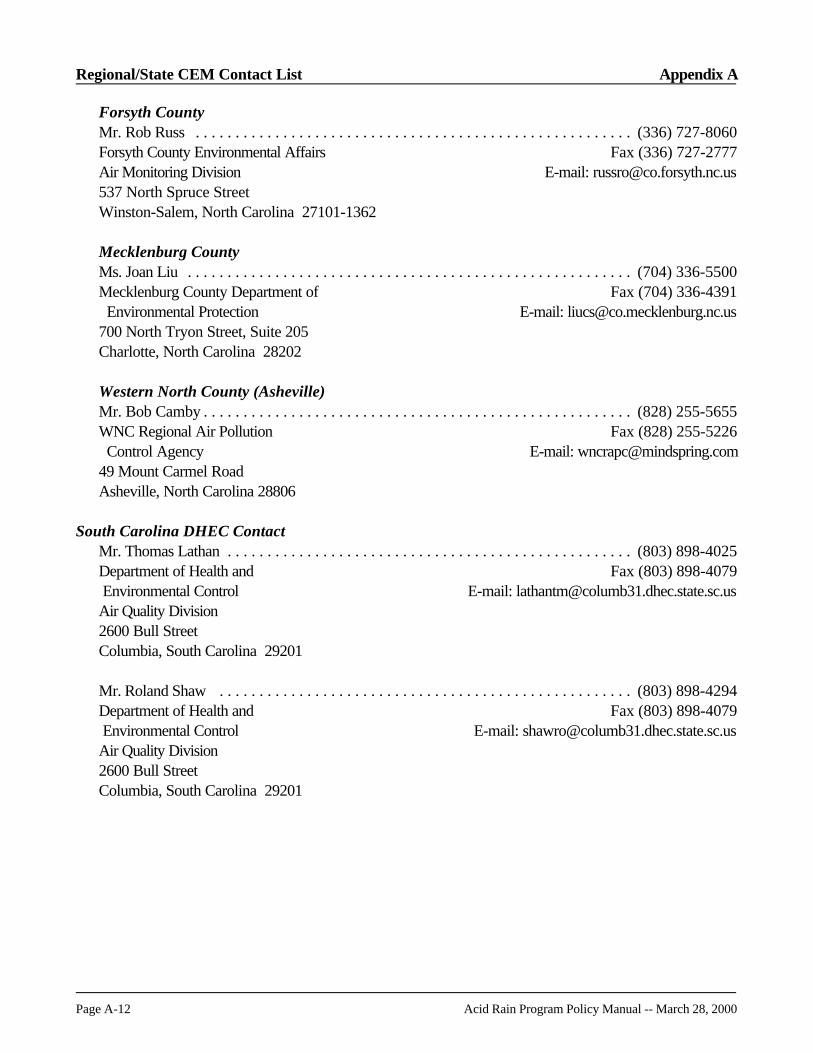
Regional/State CEM Contact List Appendix A
Page A-12 Acid Rain Program Policy Manual -- March 28, 2000
Forsyth CountyMr. Rob Russ . . . . . . . . . . . . . . . . . . . . . . . . . . . . . . . . . . . . . . . . . . . . . . . . . . . . . . . (336) 727-8060Forsyth County Environmental Affairs Fax (336) 727-2777Air Monitoring Division E-mail: [email protected] North Spruce StreetWinston-Salem, North Carolina 27101-1362
Mecklenburg CountyMs. Joan Liu . . . . . . . . . . . . . . . . . . . . . . . . . . . . . . . . . . . . . . . . . . . . . . . . . . . . . . . . (704) 336-5500Mecklenburg County Department of Fax (704) 336-4391 Environmental Protection E-mail: [email protected] North Tryon Street, Suite 205Charlotte, North Carolina 28202
Western North County (Asheville)Mr. Bob Camby . . . . . . . . . . . . . . . . . . . . . . . . . . . . . . . . . . . . . . . . . . . . . . . . . . . . . . (828) 255-5655WNC Regional Air Pollution Fax (828) 255-5226 Control Agency E-mail: [email protected] Mount Carmel RoadAsheville, North Carolina 28806
South Carolina DHEC ContactMr. Thomas Lathan . . . . . . . . . . . . . . . . . . . . . . . . . . . . . . . . . . . . . . . . . . . . . . . . . . . (803) 898-4025Department of Health and Fax (803) 898-4079 Environmental Control E-mail: [email protected] Quality Division2600 Bull StreetColumbia, South Carolina 29201
Mr. Roland Shaw . . . . . . . . . . . . . . . . . . . . . . . . . . . . . . . . . . . . . . . . . . . . . . . . . . . . (803) 898-4294Department of Health and Fax (803) 898-4079 Environmental Control E-mail: [email protected] Quality Division2600 Bull StreetColumbia, South Carolina 29201

Appendix A Regional/State CEM Contact List
Acid Rain Program Policy Manual -- March 28, 2000 Page A-13
Tennessee DAPC/Local ContactsMr. Jeryl Stewart . . . . . . . . . . . . . . . . . . . . . . . . . . . . . . . . . . . . . . . . . . . . . . . . . . . . (615) 532-0605Division of Air Pollution Control Fax (615) 532-0614Tennessee Department ofEnvironment and ConservationL&C Annex, 9th Floor401 Church StreetNashville, Tennessee 37243-1531
Chattanooga-Hamilton CountyMr. Errol Reksten . . . . . . . . . . . . . . . . . . . . . . . . . . . . . . . . . . . . . . . . . . . . . . . . . . . . (423) 867-4321Chattanooga-Hamilton County Fax (423) 867-4348Air Pollution Control Bureau E-mail: [email protected] Rossville Blvd.Chattanooga, Tennessee 37407
Knox CountyMr. Chris Sharp . . . . . . . . . . . . . . . . . . . . . . . . . . . . . . . . . . . . . . . . . . . . . . . . . . . . . . (423) 215-2488Department of Air Quality Management Fax (423) 215-4242400 Main Street, Suite 339 E-mail: [email protected], Tennessee 37902-2405
Ms. Mary Lee . . . . . . . . . . . . . . . . . . . . . . . . . . . . . . . . . . . . . . . . . . . . . . . . . . . . . . . (423) 215-2488Department of Air Quality Management Fax (423) 215-4242400 Main Street; Suite 339Knoxville, Tennessee 37902-2405
Memphis-Shelby CountyMr. George King . . . . . . . . . . . . . . . . . . . . . . . . . . . . . . . . . . . . . . . . . . . . . . . . . . . . . (901) 544-7302Memphis-Shelby County Health Department Fax (901) 544-7310Pollution Control Section814 Jefferson AvenueMemphis, Tennessee 38105
Nashville-Davidson CountyMr. Rob Raney . . . . . . . . . . . . . . . . . . . . . . . . . . . . . . . . . . . . . . . . . . . . . . . . . . . . . . (615) 340-5653Metro Health Department Fax (615) 340-2142Pollution Control Division E-mail: [email protected] Twenty-third Avenue NorthNashville, Tennessee 37203
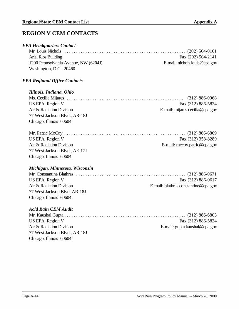
Regional/State CEM Contact List Appendix A
Page A-14 Acid Rain Program Policy Manual -- March 28, 2000
REGION V CEM CONTACTS
EPA Headquarters ContactMr. Louis Nichols . . . . . . . . . . . . . . . . . . . . . . . . . . . . . . . . . . . . . . . . . . . . . . . . . . . . (202) 564-0161Ariel Rios Building Fax (202) 564-21411200 Pennsylvania Avenue, NW (6204J) E-mail: [email protected], D.C. 20460
EPA Regional Office Contacts
Illinois, Indiana, OhioMs. Cecilia Mijares . . . . . . . . . . . . . . . . . . . . . . . . . . . . . . . . . . . . . . . . . . . . . . . . . . (312) 886-0968US EPA, Region V Fax (312) 886-5824Air & Radiation Division E-mail: [email protected] West Jackson Blvd., AR-18JChicago, Illinois 60604
Mr. Patric McCoy . . . . . . . . . . . . . . . . . . . . . . . . . . . . . . . . . . . . . . . . . . . . . . . . . . . . (312) 886-6869US EPA, Region V Fax (312) 353-8289Air & Radiation Division E-mail: [email protected] West Jackson Blvd., AE-17JChicago, Illinois 60604
Michigan, Minnesota, WisconsinMr. Constantine Blathras . . . . . . . . . . . . . . . . . . . . . . . . . . . . . . . . . . . . . . . . . . . . . . . (312) 886-0671US EPA, Region V Fax (312) 886-0617Air & Radiation Division E-mail: [email protected] West Jackson Blvd, AR-18JChicago, Illinois 60604
Acid Rain CEM AuditMr. Kaushal Gupta . . . . . . . . . . . . . . . . . . . . . . . . . . . . . . . . . . . . . . . . . . . . . . . . . . . . (312) 886-6803US EPA, Region V Fax (312) 886-5824Air & Radiation Division E-mail: [email protected] West Jackson Blvd., AR-18JChicago, Illinois 60604

Appendix A Regional/State CEM Contact List
Acid Rain Program Policy Manual -- March 28, 2000 Page A-15
Illinois EPA ContactMr. Shibu Vazha . . . . . . . . . . . . . . . . . . . . . . . . . . . . . . . . . . . . . . . . . . . . . . . . . . . . . (217) 524-0688Illinois Environmental Fax (217) 524-4710 Protection Agency E-mail: [email protected] of Air Pollution Control1021 North Grand Avenue EastSpringfield, Illinois 62794-9276
Indiana DEM ContactsMr. Dave Cline (primary) . . . . . . . . . . . . . . . . . . . . . . . . . . . . . . . . . . . . . . . . . . . . . . . (317) 233-5668Department of Environmental Fax (317) 233-6865 Management E-mail: [email protected] of Air Management100 North Senate AveP.O. Box 6015Indianapolis, Indiana 46206-6015
Mr. Scott Stacey . . . . . . . . . . . . . . . . . . . . . . . . . . . . . . . . . . . . . . . . . . . . . . . . . . . . . (317) 233-5670Department of Environmental Fax (317) 233-6865 Management E-mail: [email protected] of Air Management100 North Senate AveP.O. Box 6015Indianapolis, Indiana 46206-6015
Michigan DEQ-AQD/Local ContactsMs. Karen D. Kajiya-Mills . . . . . . . . . . . . . . . . . . . . . . . . . . . . . . . . . . . . . . . . . . . . . (517) 335-4874 Michigan Department of Fax (517) 241-7440 Environmental Quality E-mail: [email protected]. Box 30260Lansing, Michigan 48909
Wayne CountyMr. Philip Kurikesu . . . . . . . . . . . . . . . . . . . . . . . . . . . . . . . . . . . . . . . . . . . . . . . . . . . (313) 833 3524Air Quality Management Division Fax (313) 833-1130640 Temple, Suite 700 E-mail: [email protected], Michigan 48201
Minnesota PCA ContactMr. Tom Kosevich . . . . . . . . . . . . . . . . . . . . . . . . . . . . . . . . . . . . . . . . . . . . . . . . . . . . (651)296-7513Minnesota Pollution Control Agency Fax (651)297-2343520 Lafayette Road E-mail: [email protected] Paul, Minnesota 55155-3898

Regional/State CEM Contact List Appendix A
Page A-16 Acid Rain Program Policy Manual -- March 28, 2000
Ms. Yolanda Hernandez . . . . . . . . . . . . . . . . . . . . . . . . . . . . . . . . . . . . . . . . . . . . . . . . (651)282-9886Minnesota Pollution Control Agency Fax (651) 297-8683South District E-mail: [email protected] Lafayette RoadSt. Paul, Minnesota 55155-3898
Mr. Steve Sommer . . . . . . . . . . . . . . . . . . . . . . . . . . . . . . . . . . . . . . . . . . . . . . . . . . . . (651) 282-5851Minnesota Pollution Control Agency Fax (651) 296-8717520 Lafayette Road, MDMF E-mail: [email protected]. Paul, Minnesota 55155-3898
Ohio EPA ContactsMr. Charles Branch . . . . . . . . . . . . . . . . . . . . . . . . . . . . . . . . . . . . . . . . . . . . . . . . . . . (614) 728-1346Ohio Environmental Protection Agency Fax (614) 644-3681Air Quality Modeling and Planning E-mail: [email protected] Government Center122 South Front StreetColumbus, Ohio 43215
Ms. Tammy Van Walsen . . . . . . . . . . . . . . . . . . . . . . . . . . . . . . . . . . . . . . . . . . . . . . . (614) 644-3596Ohio Environmental Protection Agency Fax (614) 644-3681Division of Air Pollution Control E-mail: [email protected]. Box 1049Columbus, Ohio 43216-1049
Mr. Todd Brown . . . . . . . . . . . . . . . . . . . . . . . . . . . . . . . . . . . . . . . . . . . . . . . . . . . . . (614) 644-4839Ohio Environmental Protection Agency Fax (614) 644-3681Division of Air Pollution Control E-mail: [email protected]. Box 1049Columbus, Ohio 43216-1049
Wisconsin DNR ContactsMr. Joe Perez . . . . . . . . . . . . . . . . . . . . . . . . . . . . . . . . . . . . . . . . . . . . . . . . . . . . . . . (608) 266-8401Wisconsin Department Fax (608) 267-0560 of Natural Resources E-mail: [email protected] of Air ManagementP.O. Box 7921Madison, Wisconsin 53707
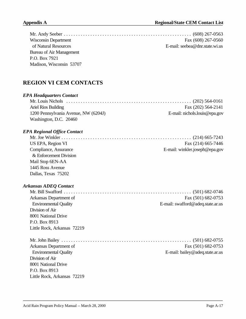
Appendix A Regional/State CEM Contact List
Acid Rain Program Policy Manual -- March 28, 2000 Page A-17
Mr. Andy Seeber . . . . . . . . . . . . . . . . . . . . . . . . . . . . . . . . . . . . . . . . . . . . . . . . . . . . . (608) 267-0563Wisconsin Department Fax (608) 267-0560 of Natural Resources E-mail: [email protected] of Air ManagementP.O. Box 7921Madison, Wisconsin 53707
REGION VI CEM CONTACTS
EPA Headquarters ContactMr. Louis Nichols . . . . . . . . . . . . . . . . . . . . . . . . . . . . . . . . . . . . . . . . . . . . . . . . . . . . (202) 564-0161Ariel Rios Building Fax (202) 564-21411200 Pennsylvania Avenue, NW (6204J) E-mail: [email protected], D.C. 20460
EPA Regional Office ContactMr. Joe Winkler . . . . . . . . . . . . . . . . . . . . . . . . . . . . . . . . . . . . . . . . . . . . . . . . . . . . . . (214) 665-7243US EPA, Region VI Fax (214) 665-7446Compliance, Assurance E-mail: [email protected] & Enforcement DivisionMail Stop 6EN-AA1445 Ross AvenueDallas, Texas 75202
Arkansas ADEQ ContactMr. Bill Swafford . . . . . . . . . . . . . . . . . . . . . . . . . . . . . . . . . . . . . . . . . . . . . . . . . . . . . (501) 682-0746Arkansas Department of Fax (501) 682-0753 Environmental Quality E-mail: [email protected] of Air8001 National DriveP.O. Box 8913Little Rock, Arkansas 72219
Mr. John Bailey . . . . . . . . . . . . . . . . . . . . . . . . . . . . . . . . . . . . . . . . . . . . . . . . . . . . . . (501) 682-0755Arkansas Department of Fax (501) 682-0753 Environmental Quality E-mail: [email protected] of Air8001 National DriveP.O. Box 8913Little Rock, Arkansas 72219
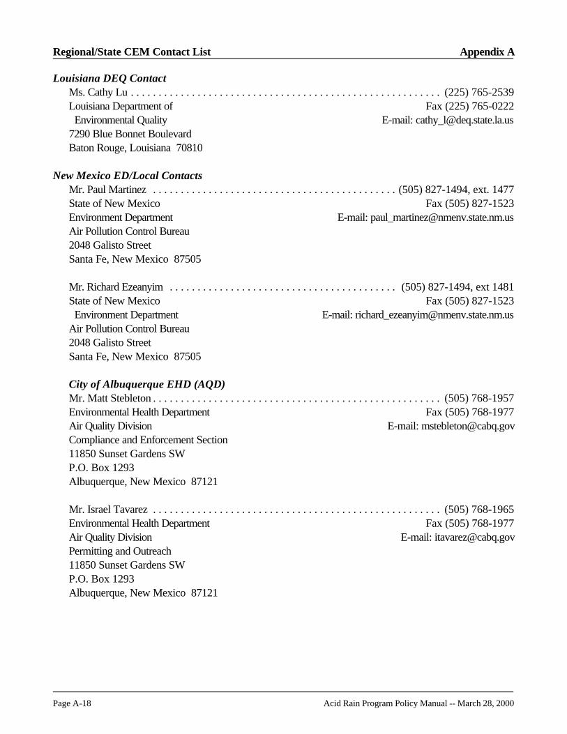
Regional/State CEM Contact List Appendix A
Page A-18 Acid Rain Program Policy Manual -- March 28, 2000
Louisiana DEQ ContactMs. Cathy Lu . . . . . . . . . . . . . . . . . . . . . . . . . . . . . . . . . . . . . . . . . . . . . . . . . . . . . . . . (225) 765-2539Louisiana Department of Fax (225) 765-0222 Environmental Quality E-mail: [email protected] Blue Bonnet BoulevardBaton Rouge, Louisiana 70810
New Mexico ED/Local ContactsMr. Paul Martinez . . . . . . . . . . . . . . . . . . . . . . . . . . . . . . . . . . . . . . . . . . . . (505) 827-1494, ext. 1477State of New Mexico Fax (505) 827-1523Environment Department E-mail: [email protected] Pollution Control Bureau2048 Galisto StreetSanta Fe, New Mexico 87505
Mr. Richard Ezeanyim . . . . . . . . . . . . . . . . . . . . . . . . . . . . . . . . . . . . . . . . . (505) 827-1494, ext 1481State of New Mexico Fax (505) 827-1523 Environment Department E-mail: [email protected] Pollution Control Bureau2048 Galisto StreetSanta Fe, New Mexico 87505
City of Albuquerque EHD (AQD)Mr. Matt Stebleton . . . . . . . . . . . . . . . . . . . . . . . . . . . . . . . . . . . . . . . . . . . . . . . . . . . . (505) 768-1957Environmental Health Department Fax (505) 768-1977Air Quality Division E-mail: [email protected] and Enforcement Section11850 Sunset Gardens SWP.O. Box 1293Albuquerque, New Mexico 87121
Mr. Israel Tavarez . . . . . . . . . . . . . . . . . . . . . . . . . . . . . . . . . . . . . . . . . . . . . . . . . . . . (505) 768-1965Environmental Health Department Fax (505) 768-1977Air Quality Division E-mail: [email protected] and Outreach11850 Sunset Gardens SWP.O. Box 1293Albuquerque, New Mexico 87121
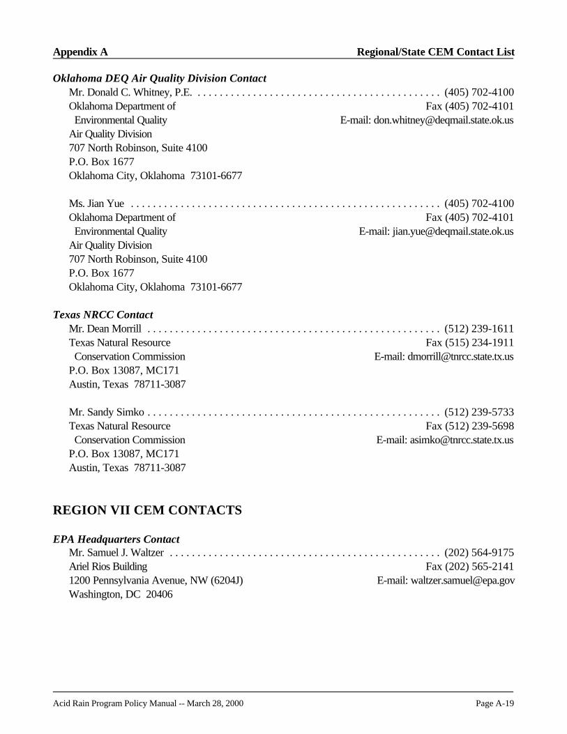
Appendix A Regional/State CEM Contact List
Acid Rain Program Policy Manual -- March 28, 2000 Page A-19
Oklahoma DEQ Air Quality Division ContactMr. Donald C. Whitney, P.E. . . . . . . . . . . . . . . . . . . . . . . . . . . . . . . . . . . . . . . . . . . . . (405) 702-4100Oklahoma Department of Fax (405) 702-4101 Environmental Quality E-mail: [email protected] Quality Division707 North Robinson, Suite 4100P.O. Box 1677Oklahoma City, Oklahoma 73101-6677
Ms. Jian Yue . . . . . . . . . . . . . . . . . . . . . . . . . . . . . . . . . . . . . . . . . . . . . . . . . . . . . . . . (405) 702-4100Oklahoma Department of Fax (405) 702-4101 Environmental Quality E-mail: [email protected] Quality Division707 North Robinson, Suite 4100P.O. Box 1677Oklahoma City, Oklahoma 73101-6677
Texas NRCC ContactMr. Dean Morrill . . . . . . . . . . . . . . . . . . . . . . . . . . . . . . . . . . . . . . . . . . . . . . . . . . . . . (512) 239-1611Texas Natural Resource Fax (515) 234-1911 Conservation Commission E-mail: [email protected]. Box 13087, MC171Austin, Texas 78711-3087
Mr. Sandy Simko . . . . . . . . . . . . . . . . . . . . . . . . . . . . . . . . . . . . . . . . . . . . . . . . . . . . . (512) 239-5733Texas Natural Resource Fax (512) 239-5698 Conservation Commission E-mail: [email protected]. Box 13087, MC171Austin, Texas 78711-3087
REGION VII CEM CONTACTS
EPA Headquarters ContactMr. Samuel J. Waltzer . . . . . . . . . . . . . . . . . . . . . . . . . . . . . . . . . . . . . . . . . . . . . . . . . (202) 564-9175Ariel Rios Building Fax (202) 565-21411200 Pennsylvania Avenue, NW (6204J) E-mail: [email protected], DC 20406

Regional/State CEM Contact List Appendix A
Page A-20 Acid Rain Program Policy Manual -- March 28, 2000
EPA Regional Office ContactMr. Jon Knodel . . . . . . . . . . . . . . . . . . . . . . . . . . . . . . . . . . . . . . . . . . . . . . . . . . . . . . (913) 551-7622US EPA, Region VII Fax (913) 551-7844901 North 5th Street E-mail: [email protected](ARTD/APCO)Kansas City, Kansas 66101
Mr. Scott Postma . . . . . . . . . . . . . . . . . . . . . . . . . . . . . . . . . . . . . . . . . . . . . . . . . . . . . (913) 551-7048US EPA, Region VII Fax (913) 551-8752901 North 5th Street E-mail: [email protected](ARTX/ENSV/ARCM)Kansas City, Kansas 66101
Iowa DNR ContactMr. Mark Stone . . . . . . . . . . . . . . . . . . . . . . . . . . . . . . . . . . . . . . . . . . . . . . . . . . . . . . (515) 242-6001Department of Natural Resources Fax (515) 242-5094Air Quality Bureau E-mail: [email protected] Hickman RoadSuite #1Urbandale, Iowa 50322
Missouri DNR APCP ContactMr. Peter Yronwode (primary) . . . . . . . . . . . . . . . . . . . . . . . . . . . . . . . . . . . . . . . . . . (573) 751-4817Missouri Department of Fax (573) 751-2706 Natural Resources E-mail: [email protected] Pollution Control ProgramP.O. Box 176Jefferson City, Missouri 65102
Ms. Patricia Pride . . . . . . . . . . . . . . . . . . . . . . . . . . . . . . . . . . . . . . . . . . . . . . . . . . . . . (573) 751-4817Missouri Department of Fax (573) 751-2706 Natural Resources E-mail: [email protected] Pollution Control ProgramP.O. Box 176Jefferson City, Missouri 65102
Mr. Cliff Johnson . . . . . . . . . . . . . . . . . . . . . . . . . . . . . . . . . . . . . . . . . . . . . . . . . . . . . (573) 751-4817Missouri Department of Fax (573) 751-2706 Natural Resources E-mail: [email protected] Pollution Control ProgramAcid Rain Operating PermitsP.O. Box 176Jefferson City, Missouri 65102
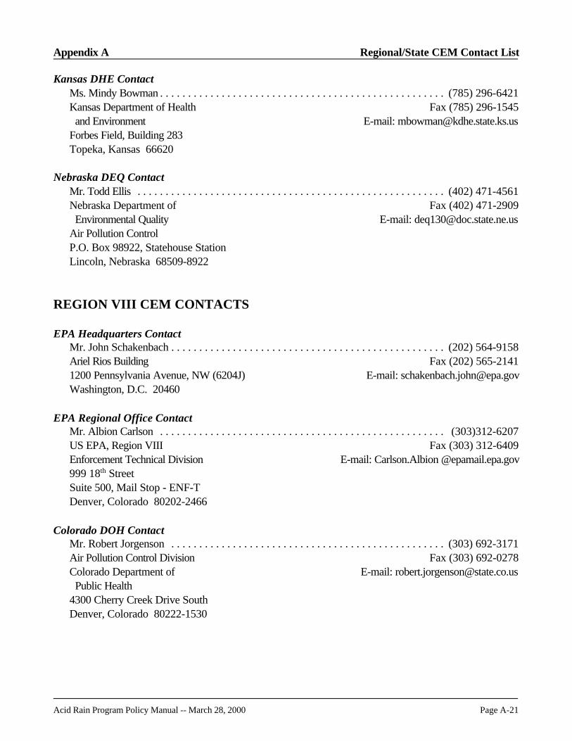
Appendix A Regional/State CEM Contact List
Acid Rain Program Policy Manual -- March 28, 2000 Page A-21
Kansas DHE ContactMs. Mindy Bowman . . . . . . . . . . . . . . . . . . . . . . . . . . . . . . . . . . . . . . . . . . . . . . . . . . . (785) 296-6421Kansas Department of Health Fax (785) 296-1545 and Environment E-mail: [email protected] Field, Building 283Topeka, Kansas 66620
Nebraska DEQ ContactMr. Todd Ellis . . . . . . . . . . . . . . . . . . . . . . . . . . . . . . . . . . . . . . . . . . . . . . . . . . . . . . . (402) 471-4561Nebraska Department of Fax (402) 471-2909 Environmental Quality E-mail: [email protected] Pollution ControlP.O. Box 98922, Statehouse StationLincoln, Nebraska 68509-8922
REGION VIII CEM CONTACTS
EPA Headquarters ContactMr. John Schakenbach . . . . . . . . . . . . . . . . . . . . . . . . . . . . . . . . . . . . . . . . . . . . . . . . . (202) 564-9158Ariel Rios Building Fax (202) 565-21411200 Pennsylvania Avenue, NW (6204J) E-mail: [email protected], D.C. 20460
EPA Regional Office ContactMr. Albion Carlson . . . . . . . . . . . . . . . . . . . . . . . . . . . . . . . . . . . . . . . . . . . . . . . . . . . (303)312-6207US EPA, Region VIII Fax (303) 312-6409Enforcement Technical Division E-mail: Carlson.Albion @epamail.epa.gov999 18th StreetSuite 500, Mail Stop - ENF-TDenver, Colorado 80202-2466
Colorado DOH ContactMr. Robert Jorgenson . . . . . . . . . . . . . . . . . . . . . . . . . . . . . . . . . . . . . . . . . . . . . . . . . (303) 692-3171Air Pollution Control Division Fax (303) 692-0278Colorado Department of E-mail: [email protected] Public Health4300 Cherry Creek Drive SouthDenver, Colorado 80222-1530

Regional/State CEM Contact List Appendix A
Page A-22 Acid Rain Program Policy Manual -- March 28, 2000
Mr. Mark Kendra (AFS) . . . . . . . . . . . . . . . . . . . . . . . . . . . . . . . . . . . . . . . . . . . . . . . (303) 692-3172Air Pollution Control Division Fax (303) 692-0278Colorado Department of E-mail: [email protected] Public Health4300 Cherry Creek Drive SouthDenver, Colorado 80222-1530
Mr. Harry Collier . . . . . . . . . . . . . . . . . . . . . . . . . . . . . . . . . . . . . . . . . . . . . . . . . . . . . (303) 692-3178Air Pollution Control Division Fax (303) 692-0278Colorado Department of E-mail: [email protected] Public Health4300 Cherry Creek Drive SouthDenver, Colorado 80222-1530
Mr. Dave Ouimette . . . . . . . . . . . . . . . . . . . . . . . . . . . . . . . . . . . . . . . . . . . . . . . . . . . (303) 692-3178Air Pollution Control Division Fax (303) 692-0278Colorado Department of E-mail: [email protected] Public Health4300 Cherry Creek Drive SouthDenver, Colorado 80222-1530
Mr. Long Nguyen . . . . . . . . . . . . . . . . . . . . . . . . . . . . . . . . . . . . . . . . . . . . . . . . . . . . . (303) 692-3106Air Pollution Control Division Fax (303) 692-0278Colorado Department of E-mail: [email protected] Public Health4300 Cherry Creek Drive SouthDenver, Colorado 80222-1530
Montana DEQ ContactsMs. Karen Clavin . . . . . . . . . . . . . . . . . . . . . . . . . . . . . . . . . . . . . . . . . . . . . . . . . . . . . (406) 444-0282Air and Waste Management Bureau Fax (406) 444-1499Permitting and Compliance Division E-mail: [email protected] of Environmental QualityMecalf Building, 1520 E Sixth AvenueP.O. Box 200901Helena, Montana 59620-0901
Mr. Eric Kopczynski . . . . . . . . . . . . . . . . . . . . . . . . . . . . . . . . . . . . . . . . . . . . . . . . . . (406) 247-4453Air and Waste Management Bureau Fax (406) 247-4456Airport Industrial Park E-mail: [email protected] Rimtop DriveBillings, Montana 59105

Appendix A Regional/State CEM Contact List
Acid Rain Program Policy Manual -- March 28, 2000 Page A-23
North Dakota DOH ContactMr. Jim Semerad . . . . . . . . . . . . . . . . . . . . . . . . . . . . . . . . . . . . . . . . . . . . . . . . . . . . . (701) 328-5188State Department of Health Fax (701) 328-5200Division of Environmental Engineering E-mail: [email protected] Missouri AvenueP.O. Box 5520Bismark, North Dakota 58506-5520
Mr. Dana Mount . . . . . . . . . . . . . . . . . . . . . . . . . . . . . . . . . . . . . . . . . . . . . . . . . . . . . (701) 328-5188State Department of Health Fax (701) 328-5200Division of Environmental Engineering E-mail: [email protected] Missouri AvenueP.O. Box 5520Bismark, North Dakota 58506-5520
South Dakota DER ContactsMr. Kyrik Rombough . . . . . . . . . . . . . . . . . . . . . . . . . . . . . . . . . . . . . . . . . . . . . . . . . . (605) 773-7171Department of Environment Fax (605) 773-5286 and Natural Resources E-mail: [email protected] of Environmental RegulationJoe Foss BuildingPierre, South Dakota 57501
Utah DEQ ContactMr. Norm Erikson . . . . . . . . . . . . . . . . . . . . . . . . . . . . . . . . . . . . . . . . . . . . . . . . . . . . (801) 536-4063Department of Environmental Quality Fax (801) 536-4099Division of Air Quality E-mail: [email protected] North, 1950 WestP.O. Box 14480Salt Lake City, Utah 84114-4820
Ms. Susan Weisenberg . . . . . . . . . . . . . . . . . . . . . . . . . . . . . . . . . . . . . . . . . . . . . . . . . (801) 536-4045Department of Environmental Quality Fax (801) 536-4099Division of Air Quality E-mail: [email protected] North, 1950 WestP.O. Box 14480Salt Lake City, Utah 84114-4820
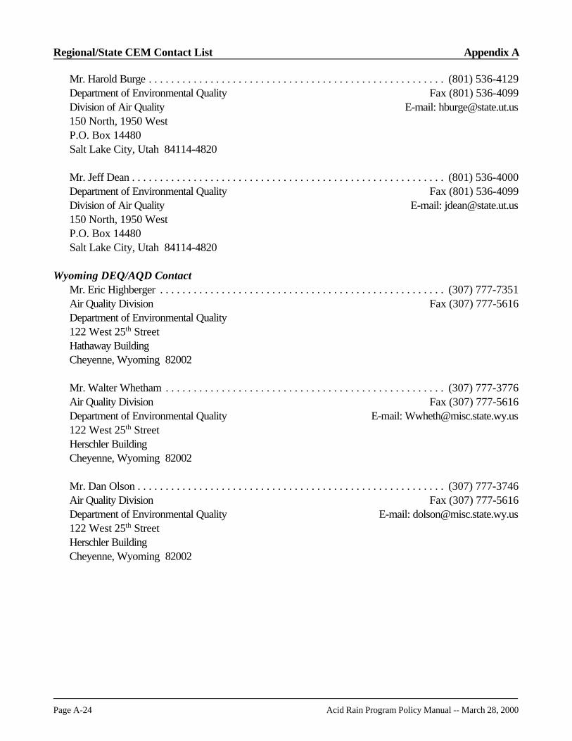
Regional/State CEM Contact List Appendix A
Page A-24 Acid Rain Program Policy Manual -- March 28, 2000
Mr. Harold Burge . . . . . . . . . . . . . . . . . . . . . . . . . . . . . . . . . . . . . . . . . . . . . . . . . . . . . (801) 536-4129Department of Environmental Quality Fax (801) 536-4099Division of Air Quality E-mail: [email protected] North, 1950 WestP.O. Box 14480Salt Lake City, Utah 84114-4820
Mr. Jeff Dean . . . . . . . . . . . . . . . . . . . . . . . . . . . . . . . . . . . . . . . . . . . . . . . . . . . . . . . . (801) 536-4000Department of Environmental Quality Fax (801) 536-4099Division of Air Quality E-mail: [email protected] North, 1950 WestP.O. Box 14480Salt Lake City, Utah 84114-4820
Wyoming DEQ/AQD ContactMr. Eric Highberger . . . . . . . . . . . . . . . . . . . . . . . . . . . . . . . . . . . . . . . . . . . . . . . . . . . (307) 777-7351Air Quality Division Fax (307) 777-5616Department of Environmental Quality122 West 25th StreetHathaway BuildingCheyenne, Wyoming 82002
Mr. Walter Whetham . . . . . . . . . . . . . . . . . . . . . . . . . . . . . . . . . . . . . . . . . . . . . . . . . . (307) 777-3776Air Quality Division Fax (307) 777-5616Department of Environmental Quality E-mail: [email protected] West 25th StreetHerschler BuildingCheyenne, Wyoming 82002
Mr. Dan Olson . . . . . . . . . . . . . . . . . . . . . . . . . . . . . . . . . . . . . . . . . . . . . . . . . . . . . . . (307) 777-3746Air Quality Division Fax (307) 777-5616Department of Environmental Quality E-mail: [email protected] West 25th StreetHerschler BuildingCheyenne, Wyoming 82002
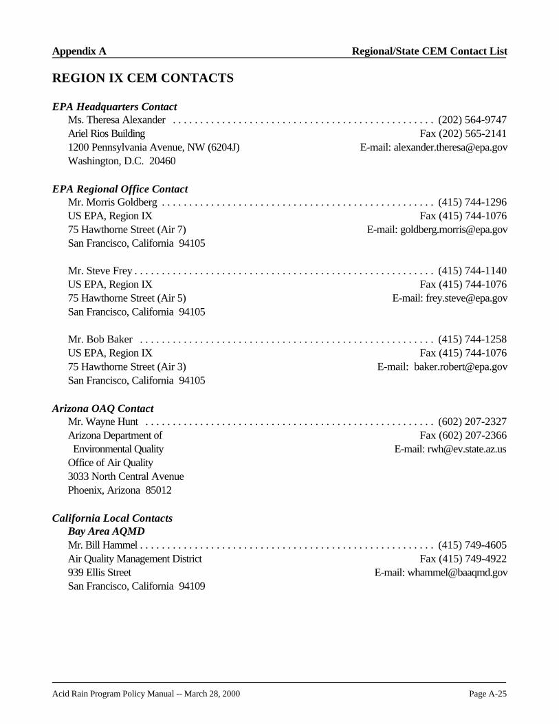
Appendix A Regional/State CEM Contact List
Acid Rain Program Policy Manual -- March 28, 2000 Page A-25
REGION IX CEM CONTACTS
EPA Headquarters ContactMs. Theresa Alexander . . . . . . . . . . . . . . . . . . . . . . . . . . . . . . . . . . . . . . . . . . . . . . . . (202) 564-9747Ariel Rios Building Fax (202) 565-21411200 Pennsylvania Avenue, NW (6204J) E-mail: [email protected], D.C. 20460
EPA Regional Office ContactMr. Morris Goldberg . . . . . . . . . . . . . . . . . . . . . . . . . . . . . . . . . . . . . . . . . . . . . . . . . . (415) 744-1296US EPA, Region IX Fax (415) 744-107675 Hawthorne Street (Air 7) E-mail: [email protected] Francisco, California 94105
Mr. Steve Frey . . . . . . . . . . . . . . . . . . . . . . . . . . . . . . . . . . . . . . . . . . . . . . . . . . . . . . . (415) 744-1140US EPA, Region IX Fax (415) 744-107675 Hawthorne Street (Air 5) E-mail: [email protected] Francisco, California 94105
Mr. Bob Baker . . . . . . . . . . . . . . . . . . . . . . . . . . . . . . . . . . . . . . . . . . . . . . . . . . . . . . (415) 744-1258US EPA, Region IX Fax (415) 744-107675 Hawthorne Street (Air 3) E-mail: [email protected] Francisco, California 94105
Arizona OAQ ContactMr. Wayne Hunt . . . . . . . . . . . . . . . . . . . . . . . . . . . . . . . . . . . . . . . . . . . . . . . . . . . . . (602) 207-2327Arizona Department of Fax (602) 207-2366 Environmental Quality E-mail: [email protected] of Air Quality3033 North Central AvenuePhoenix, Arizona 85012
California Local ContactsBay Area AQMDMr. Bill Hammel . . . . . . . . . . . . . . . . . . . . . . . . . . . . . . . . . . . . . . . . . . . . . . . . . . . . . . (415) 749-4605Air Quality Management District Fax (415) 749-4922939 Ellis Street E-mail: [email protected] Francisco, California 94109

Regional/State CEM Contact List Appendix A
Page A-26 Acid Rain Program Policy Manual -- March 28, 2000
Mojave Desert AQMDMr. Elden Heaston (760) 245-1661, ext 5737Mojave Desert Air Quality Fax (760) 245-2699 Management District E-mail: [email protected] Civic Drive, Suite 200Victorville, California 92392
Monterey Bay Unified APCDMr. Larry Borrelli . . . . . . . . . . . . . . . . . . . . . . . . . . . . . . . . . . . . . . . . . . . . . . . . . . . . . (831) 647-9411Air Pollution Control District Fax (831) 647-850124580 Silver Cloud Court E-mail: [email protected], California 93940
San Diego APCDMs. Suzanne Blackburn . . . . . . . . . . . . . . . . . . . . . . . . . . . . . . . . . . . . . . . . . . (619) or(858) 694-8972Air Pollution Control District Fax (619) or (858) 694-38589150 Chesapeake Drive E-mail: [email protected] Diego, California 92123
San Luis Obispo County APCDMr. Gary Willey . . . . . . . . . . . . . . . . . . . . . . . . . . . . . . . . . . . . . . . . . . . . . . . . . . . . . . (805) 781-5912Air Pollution Control District Fax (805) 546-10353433 Roberto Court E-mail: [email protected] Luis Obispo, California 93401
South Coast AQMDMr. Dipankar Sarkar . . . . . . . . . . . . . . . . . . . . . . . . . . . . . . . . . . . . . . . . . . . . . . . . . . (909) 396-2273South Coast AQMD Fax (909) 396-2099Monitoring & Analysis E-mail: [email protected] East Copley Drive Diamond Bar, California 91765
Ventura County APCDMr. Kerby Zozula . . . . . . . . . . . . . . . . . . . . . . . . . . . . . . . . . . . . . . . . . . . . . . . . . . . . (805) 645-1421Air Pollution Control District Fax (805) 645-1444669 County Square Drive E-mail: [email protected] FloorVentura County, California 93003
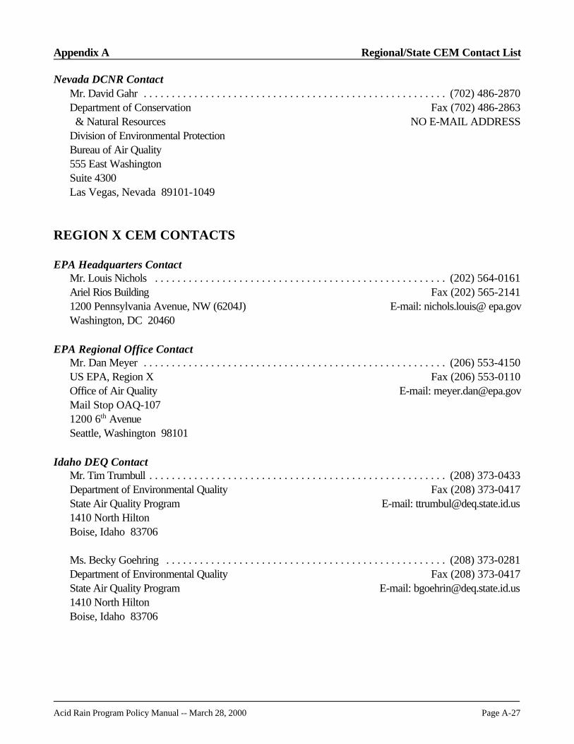
Appendix A Regional/State CEM Contact List
Acid Rain Program Policy Manual -- March 28, 2000 Page A-27
Nevada DCNR ContactMr. David Gahr . . . . . . . . . . . . . . . . . . . . . . . . . . . . . . . . . . . . . . . . . . . . . . . . . . . . . . (702) 486-2870Department of Conservation Fax (702) 486-2863 & Natural Resources NO E-MAIL ADDRESSDivision of Environmental ProtectionBureau of Air Quality555 East WashingtonSuite 4300Las Vegas, Nevada 89101-1049
REGION X CEM CONTACTS
EPA Headquarters ContactMr. Louis Nichols . . . . . . . . . . . . . . . . . . . . . . . . . . . . . . . . . . . . . . . . . . . . . . . . . . . . (202) 564-0161Ariel Rios Building Fax (202) 565-21411200 Pennsylvania Avenue, NW (6204J) E-mail: nichols.louis@ epa.govWashington, DC 20460
EPA Regional Office ContactMr. Dan Meyer . . . . . . . . . . . . . . . . . . . . . . . . . . . . . . . . . . . . . . . . . . . . . . . . . . . . . . (206) 553-4150US EPA, Region X Fax (206) 553-0110Office of Air Quality E-mail: [email protected] Stop OAQ-1071200 6th AvenueSeattle, Washington 98101
Idaho DEQ ContactMr. Tim Trumbull . . . . . . . . . . . . . . . . . . . . . . . . . . . . . . . . . . . . . . . . . . . . . . . . . . . . . (208) 373-0433Department of Environmental Quality Fax (208) 373-0417State Air Quality Program E-mail: [email protected] North HiltonBoise, Idaho 83706
Ms. Becky Goehring . . . . . . . . . . . . . . . . . . . . . . . . . . . . . . . . . . . . . . . . . . . . . . . . . . (208) 373-0281Department of Environmental Quality Fax (208) 373-0417State Air Quality Program E-mail: [email protected] North HiltonBoise, Idaho 83706

Regional/State CEM Contact List Appendix A
Page A-28 Acid Rain Program Policy Manual -- March 28, 2000
Oregon DEQ ContactBendMr. Mark Fisher . . . . . . . . . . . . . . . . . . . . . . . . . . . . . . . . . . . . . . . . . . . . . . (541) 388-6146, ext. 275Department of Environmental Quality Fax (541) 388-82832146 North East 4th Street E-mail: [email protected] Bend, Oregon 97701
Mr. Thane Jennings . . . . . . . . . . . . . . . . . . . . . . . . . . . . . . . . . . . . . . . . . . . . (541) 388-6146, ext. 247Department of Environmental Quality Fax (541) 388-82832146 North East 4th Street E-mail: [email protected], Oregon 97701
Washington DOE/Local ContactsMr. Alex Piliaris . . . . . . . . . . . . . . . . . . . . . . . . . . . . . . . . . . . . . . . . . . . . . . . . . . . . . . (360) 407-6811Department of Ecology Fax (360) 407-6802Air Quality Program E-mail: [email protected]. Box 47600Olympia, Washington 98504-7600
NorthwestMr. Axel Franzmann . . . . . . . . . . . . . . . . . . . . . . . . . . . . . . . . . . . . . . . . . . . . (360) 428-1617, ext. 211Northwest Air Pollution Authority Fax (360) 428-16201600 South 2nd Street E-mail: [email protected] Vernon, Washington 98273-5202
Puget Sound APCAMr. Fred Austin . . . . . . . . . . . . . . . . . . . . . . . . . . . . . . . . . . . . . . . . . . . . . . . . . . . . . . (206) 689-4055Puget Sound Clean Air Agency Fax (206) 343-7522110 Union Street, Suite 500 E-mail: [email protected], Washington 98101-2038
Mr. Gerry Pade . . . . . . . . . . . . . . . . . . . . . . . . . . . . . . . . . . . . . . . . . . . . . . . . . . . . . . (206) 689-4065Puget Sound Clean Air Agency Fax (206) 343-7522110 Union Street, Suite 500 E-mail: [email protected], Washington 98101-2038
Southwest APCAMs. Jennifer Brown (360) 574-3058, ext. 27Air Pollution Control Authority Fax (360) 576-09251308 Northeast 134th Street E-mail: [email protected], Washington 98685

Acid Rain Program Policy Manual -- March 28, 2000 Page B-i
APPENDIX BCORRESPONDENCE
Page
Letter on Recertification . . . . . . . . . . . . . . . . . . . . . . . . . . . . . . . . . . . . . . . . . . . . . . . . . . B-1
EPA's Response . . . . . . . . . . . . . . . . . . . . . . . . . . . . . . . . . . . . . . . . . . . . . . . . . . . . . . . B-2
Letter Concerning Submission of Certification Test Results to Phase I DesignatedRepresentatives in EPA Region VII . . . . . . . . . . . . . . . . . . . . . . . . . . . . . . . . . . . . . . . B-4
Memorandum on Protocol Gas Concentration Adjustments . . . . . . . . . . . . . . . . . . . . . . . . B-6
Letter on Early Election and Common Stack Continuous Emissions Monitoring . . . . . . . . B-11
Letter on NOx Monitoring for Common Stack Early Election Units . . . . . . . . . . . . . . . . . B-14
Correspondence Appendix B
Page B-ii Acid Rain Program Policy Manual -- March 28, 2000
[This page intentionally left blank]

Acid Rain Program Policy Manual -- March 28, 2000 Page B-1
Appendix B: Correspondence
Letter on Recertification
August 20, 1993
Ms. Cecilia MijaresU.S. EPA Region 5Air and Radiation Divisions (AE-17J)77 West Jackson BoulevardChicago IL 60604
Dear Ms. Mijares:
Electric Energy, Inc. (EEI) is planning to replace the orifices in the sample probes for the continuousEmissions Monitoring System (CEMS) with one that is not an exact duplicate. It will, however, provide thesame concentration of diluted sample to the analyzers. EEI request confirmation that replacement of thesample orifice in the CEMS dilution probe will not require re-certification of the monitors.
EEI has the dilution type CEM system. This system extracts a sample of gas from the stack and dilutes it withair at a ratio of 150:1. An orifice is used to meter the stack gas sample flow to the mixing chamber. Instrument air is added until the 150:1 dilution ratio is achieved.
EEI installed the system this year and went through field certification in June. Based on recent operatingexperience, EEI believes that changing the stack gas sample orifice to a smaller one will increase the reliabilityof the system. We have found that our current orifice does not respond as desired to small changes in airfrom the air supply. The new orifice will be more tolerant to air supply fluctuation and, therefore, shouldprovide more reliable readings. This smaller orifice will still provide a 150:1 dilution ratio, but will require lessinstrument air to do it. Because the stack gas sample dilution ratio will remain constant, the operating range ofthe analyzers will not be affected.
In the dilution type system, calibration gas is introduced ahead of the stack gas orifice. The calibration gas isdrawn through the orifice and diluted exactly the way a stack gas sample would be. The analyzers measurethe concentration in the diluted sample. The Data Acquisition System (DAS) takes that analyzer value,multiplies it by 150 and compares it to the known bottle value. When EEI changes the orifice to the smallerone and reduce the instrument air accordingly to maintain the 150:1 dilution ratio, EEI will perform a completecalibration gas linearity check to verify that the dilution ratio is maintained.

Correspondence Appendix B
Page B-2 Acid Rain Program Policy Manual -- March 28, 2000
In summary, EEI believes that changing the sample orifice in the dilution probe does not affect the ability of thesystem to measure SO2, NOx, or CO2 concentrations and should not require complete re-certification sincethe same dilution ratio is maintained. EEI will perform a calibration gas check of the system using low, midand high concentrations of calibration gas. This check will confirm that stack gas concentrations will beaccurately measured.
At your earliest convenience, please provide confirmation that re-certification is not required so thisimprovement can be implemented in our system. If you have any questions, please contact Mr. Bruce Parkerat (618) 543-7531, extension 458.
Sincerely,
{signed}William H. SheppardPlant Manager
EPA's Response:
September 13, 1993
William H. SheppardPlant ManagerElectric Energy, IncorporatedP.O. Box 165Joppa, Illinois 62953
RE: Replacement of Sample Orifice on Acid Rain CEMS at Joppa Steam Plant, Joppa, Illinois
Dear Mr. Sheppard:
This is in response to your letter of August 20, 1993. The United States Environmental Protection Agency(USEPA) has considered your request for guidance on whether the proposed replacement of sample orificeswithin your acid rain continuous emission monitoring system (CEMS) would require recertification.
Specifically, Electric Energy, Inc. (EEI) conducted field certification testing in June 1993 on CEMS installedon units 1-6 at the Joppa Steam Plant. Based on the current performance of these CEMS, you believe thatchanging the stack gas sample orifice to a smaller one will increase the CEMS tolerance to small fluctuationsin air from the air supply, and that therefore increase the CEMS reliability. By adjusting the supply of air tocompensate for the smaller size of the replacement orifice, you will maintain the CEM's current 150:1 dilutionratio. Because the calibration gas physically passes through this stack gas sample orifice component of the
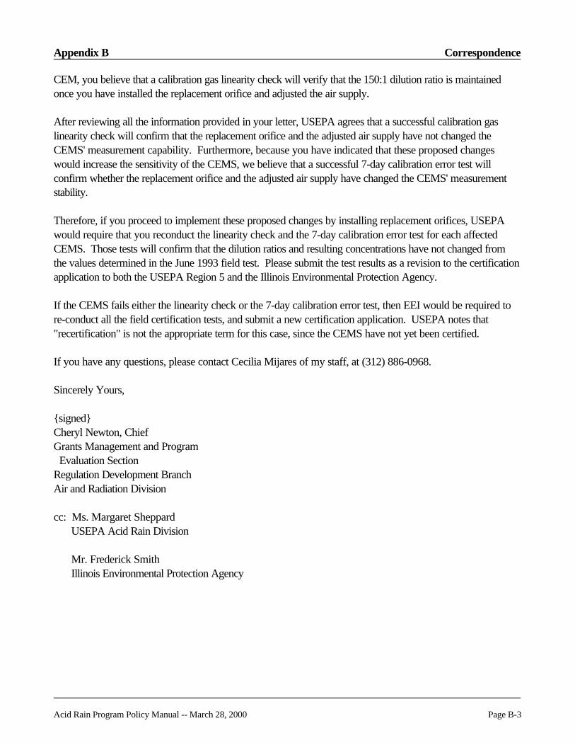
Appendix B Correspondence
Acid Rain Program Policy Manual -- March 28, 2000 Page B-3
CEM, you believe that a calibration gas linearity check will verify that the 150:1 dilution ratio is maintainedonce you have installed the replacement orifice and adjusted the air supply.
After reviewing all the information provided in your letter, USEPA agrees that a successful calibration gaslinearity check will confirm that the replacement orifice and the adjusted air supply have not changed theCEMS' measurement capability. Furthermore, because you have indicated that these proposed changeswould increase the sensitivity of the CEMS, we believe that a successful 7-day calibration error test willconfirm whether the replacement orifice and the adjusted air supply have changed the CEMS' measurementstability.
Therefore, if you proceed to implement these proposed changes by installing replacement orifices, USEPAwould require that you reconduct the linearity check and the 7-day calibration error test for each affectedCEMS. Those tests will confirm that the dilution ratios and resulting concentrations have not changed fromthe values determined in the June 1993 field test. Please submit the test results as a revision to the certificationapplication to both the USEPA Region 5 and the Illinois Environmental Protection Agency.
If the CEMS fails either the linearity check or the 7-day calibration error test, then EEI would be required tore-conduct all the field certification tests, and submit a new certification application. USEPA notes that"recertification" is not the appropriate term for this case, since the CEMS have not yet been certified.
If you have any questions, please contact Cecilia Mijares of my staff, at (312) 886-0968.
Sincerely Yours,
{signed}Cheryl Newton, ChiefGrants Management and Program Evaluation SectionRegulation Development BranchAir and Radiation Division
cc: Ms. Margaret SheppardUSEPA Acid Rain Division
Mr. Frederick SmithIllinois Environmental Protection Agency

Correspondence Appendix B
Page B-4 Acid Rain Program Policy Manual -- March 28, 2000
Letter Concerning Submission of Certification Test Results to Phase IDesignated Representatives in EPA Region VII
dated October 1, 1993
{Address of DR}
Dear {name of DR}:
Over the past several months, the Region 7 Acid Rain Program continuous emission monitoring team hasparticipated in a number of pre-test meetings and on-site test activities. We've observed much confusionabout how certification results are to be submitted; whether in a hardcopy report, on magnetic media(diskette) or on both formats. This letter is intended to clarify exactly what information, and in what format,test results are to be submitted to the regional office.
For monitors to quality for certification, Part 75 requires "magnetic" submission of all certification testresults in the format specified by the Electronic Data Reporting (EDR) instruction, Version 1.1 (copyenclosed). In particular, the certification data must be submitted on an IBM compatible 3-1/2" or 5-1/4" highdensity floppy disk. Furthermore, each electronic report submission must be a single ASCII flat filecomposed of variable length records with each Record Type exactly following the format specified in the EDRinstructions. It is important to note that spreadsheet and database files neither meet the requirement of beingASCII flat files nor do they satisfy the format specifications in the EDR instructions.
So far, Region 7 has received only one diskette containing certification test data. The diskette contained anumber of spreadsheet files (non-ASCII readable) and only one ASCII-readable file of minute-by-minute testresults of unknown origin. The only ASCII-readable file was not in the format described in the EDRinstructions. As a consequence the diskette was unreadable by EPA's certification results review softwareand could not be processed.
Besides meeting the format specified in the EDR instructions, each submitted diskette must contain theinformation listed in EDR Tables 3 (Monitoring Plan Information) and 4 (Test Information), along with Table2, Record-type 100 (Facility Information). The certification test results data file must be sorted in facility-unit-component-test data order, i.e.,
Rec 100 Facility informationRec 500 Monitoring plan unit definition table...Unit 1Rec 501 Monitoring plan common stack definition table...Unit 1Rec 510 Monitoring system component table...Component ARec 600-631 Test information...Component ARec 510 Monitoring system component table...Component BRec 600-631 Test information...Component B
.....etc.....Rec 500 Monitoring plan unit definition table...Unit 2Rec 501 Monitoring plan common stack definition table...Unit 2Rec 510 Monitoring system component table...Component A

Appendix B Correspondence
Acid Rain Program Policy Manual -- March 28, 2000 Page B-5
Rec 600-631 Test information...Component ARec 510 Monitoring system component table...Component BRec 600-631 Test information...Component B
.....etc.....
Enclosed is an "example" hardcopy printout containing hypothetical data showing how the ASCII filemight look if properly constructed. As a clarification to the EDR instructions, you may exclude Record Type520 (formula table) from the certification results data file. Likewise, if not seeking approval for an alternativemonitoring system, Record Types 630 (alternative monitoring system data) and 631 (alternative monitoringsystem results and statistics) are not necessary. We request that you include two copies of the certificationresults diskette, one for the regional office and one for the Acid Rain Division, with your certificationapplication(s).
The region also requires, as part of our standard operating procedure, a hardcopy report of all test results,calculations, calibration data, plant operating data, and other information described in the enclosed reportoutline. Much of this information cannot easily be put on or read in electronic format and is only useful inhardcopy format. Additionally, the hardcopy report provides the regional office with a permanent record ofthe certification test results and other important baseline information. We request, in addition to the twocopies provided to Region 7, that you send a copy of the hardcopy results to your respective state and localair pollution control agencies.
To avoid any unexpected surprises in preparing the electronic data file, we recommend that you consultwith your data acquisition and handling system vendor, your testing contractor, and other utility staff to ensurethat you have a mechanism to generate the required data file in the appropriate format. As previouslymentioned in our September 2, 1993 letter, your certification application cannot be considered complete untilyou submit all elements of the application, including the hardcopy certification test results report, the electroniccertification test results data file and the data acquisition and handling system verification. We hope you findthe enclosed information useful. In the meantime, if you have any question about the certification process,please give me a call at (913) 551-7622.
Sincerely,{signed}Jon KnodelAir Permits Section

Correspondence Appendix B
Page B-6 Acid Rain Program Policy Manual -- March 28, 2000
Memorandum on Protocol Gas Concentration Adjustments
UNITED STATES ENVIRONMENTAL PROTECTION AGENCYWASHINGTON, D.C. 20460
August 29, 1996
OFFICE OF AIR AND RADIATION
MEMORANDUM
SUBJECT: Implementing Protocol Gas Concentration Adjustments
FROM: Acid Rain Division
TO: Part 75 Affected Sources
Part 75 affected sources should follow the guidance in the July 24, 1996 memorandum from AndrewBond (attached). This memorandum is also available on the TTN. In addition to following the July 24memorandum, the following Part 75-specific guidance should be followed:
! Do not retrospectively correct test results from tests conducted with affected gases or resubmit emissionsdata reported from monitors calibrated with affected gases.
! Prior to January 1, 1997 (after which all calibration gases must be based on corrected standards), werecommend that utilities check the SO2 calibration gases used to calibrate the reference method monitorbefore performing a relative accuracy test audit. Verify that the SO2 calibration gases for the referencemethod monitor are consistent (adjusted or not adjusted) with the SO2 calibration gases used to calibratethe stack CEMS. If necessary, make adjustments so that all of the SO2 calibration gases are corrected tothe accurate standard.
! Any questions may be directed to the appropriate USEPA Regional Office or Acid Rain Division contact.
Appendix B Correspondence
Acid Rain Program Policy Manual -- March 28, 2000 Page B-7
UNITED STATES ENVIRONMENTAL PROTECTION AGENCYNATIONAL EXPOSURE RESEARCH LABORATORY
RESEARCH TRIANGLE PARK, NC 27711
July 24, 1996
OFFICE OF RESEARCH AND DEVELOPMENT
MEMORANDUM
SUBJECT: Guidance for SRMs and NTRMs Certified by NIST between 1989 and 1996
FROM: Andrew E. Bond, Acting ChiefQuality Assurance Branch (MD-77B)AMRD/National Exposure Research LaboratoryResearch Triangle Park, NC 27711
TO: Suppliers of Protocol Gases
The National Institute of Standards and Technology (NIST) has informed us that they are adjustingthe SO2 concentrations in the Standard Reference Materials (SRMs) and the NIST Traceable ReferenceMaterials (NTRMs) that were certified between 1989 and May 31, 1996. The adjustments are required asthe result of an intercomparison between the traditional titration method and a gravimetrically preparedstandard.
We are aware that some of these SRMs and NTRMs have been used in the past or may be used inthe future to certify Protocol Gases either directly or through the use of Gas Manufacturer's IntermediateStandards (GMISs) traceable to these SRMs and NTRMs. No later than September 1, 1996 all newProtocol Gases produced or sold are required to be based upon the adjusted SRM/NTRM value. Thisincludes gases produced using GMISs. In addition, Protocol Gases produced using adjusted SRM/NTRMsshould be tagged with a code "R" before the SRM number to indicate that the adjustment has already beenmade (i.e., "SRM 1693a" would be changed to "SRM R1693a" on the Protocol Gas certification/cylinderlabels).
Some of the Protocol Gases presently in use or previously used in conformance to 40 CFR Parts 58,60, 61 and 75 may also require an SO2 concentration "adjustment." This includes gases used for stackCEMS and reference method testing. It is acceptable to re-issue certificates and cylinder labels with thecorrected gas values. If this approach is followed, the new certificate and cylinder labels should be taggedwith a code R in the SRM number to indicate that the adjustment has been made.

Correspondence Appendix B
Page B-8 Acid Rain Program Policy Manual -- March 28, 2000
We are aware that issuing new certificates and labels for affected Protocol Gases could be costly andtime consuming. Therefore, it is also acceptable to EPA if the owners of Protocol Gases hand-correct theircertificates and cylinder labels. If this approach is followed, owners of Protocol Gases should attachdocumentation to the certificate indicating the unadjusted concentration, the adjustment factor, and the newadjusted concentration (this may include a letter from the supplier of the Protocol Gas indicating the"adjustment factor" they should use). A sample standard form and a blank form for making these handcorrections are attached. The EPA regulatory units concerned with 40 CFR Parts 58, 60, 61 and 75 haveconcurred with this approach.
Protocol Gas users must implement the adjustment no later than January 1, 1997. Each EPAregulatory unit may issue additional guidance about how this adjustment will affect their program.
We would appreciate it if you would notify your Protocol Gases users of the required "adjustment" totheir SO2 concentration. Please feel free to include a copy of this letter with your correspondence.
If you have questions please feel free to contact Ms. Avis Hines of my staff at 919-541-4001 or byFAX 919-541-7953.
Attachments
cc: Avis Hines, MD-77BBill Mitchell, MD-77BRoss Highsmith, MD-78AJim Vickery, MD-75John Silvasi, MD-14John T. Schakenbach, 6204J

Appendix B Correspondence
Acid Rain Program Policy Manual -- March 28, 2000 Page B-9
SAMPLE STANDARD FORM
EPA Cylinder GasSO2 Concentration Adjustment
Gas Cylinder Data:
Gas Supplier: Gas VendorCylinder No.: XXX123Certification Date: 7/25/96Expiration Date: 7/25/99Type of Cylinder: P(P=protocol, G=GMIS, N=NTRM, S=SRM)
Original SO2 concentration, C(SO2)ori: 90.81 ppmCorrected SO2 concentration, C(SO2)cor: 92.70 ppm
C(SO2)cor = C(SO2)ori *Fcor
Gas Standard* Data:
Standard No.: SRM-0000Corrected Standard No.: SRM-R-0000Cylinder No.: xxx-456Expiration date: 7/20/97Original concentration of the standard, Sorg: 259.8 ppmCorrect concentration of the standard, Scor: 265.2 ppm(from NIST table)Correction factor, Fcor = Scor/Sorg: 1.021
Signature: ______________________________ Date: __________________
* SRMs or NTRMs

Correspondence Appendix B
Page B-10 Acid Rain Program Policy Manual -- March 28, 2000
EPA Cylinder GasSO2 Concentration Adjustment
Gas Cylinder Data:
Gas Supplier:Cylinder No.:Certification Date:Expiration Date:Type of Cylinder:(P=protocol, G=GMIS, N=NTRM, S=SRM)
Original SO2 concentration, C(SO2)ori:Corrected SO2 concentration, C(SO2)cor:
C(SO2)cor = C(SO2)ori *Fcor
Gas Standard* Data:
Standard No.:Corrected Standard No.:Cylinder No.:Expiration date:Original concentration of the standard, Sorg:Correct concentration of the standard, Scor:(from NIST table)Correction factor, Fcor = Scor/Sorg:
Signature: ______________________________ Date: __________________
* SRMs or NTRMs

Appendix B Correspondence
Acid Rain Program Policy Manual -- March 28, 2000 Page B-11
Letter on Early Election and Common Stack Continuous Emissions Monitoring
UNITED STATES ENVIRONMENTAL PROTECTION AGENCYWASHINGTON, D.C. 20460
August 9, 1996
OFFICE OF AIR AND RADIATION
Mr. Michael CashinEnvironmental EngineerMinnesota Power30 West Superior StreetDuluth MN 55802-2093
Re: Early Election and Common Stack Continuous Emissions Monitoring
Dear Mr. Cashin:
As I indicated in my letter of July 24, 1996, I am writing to follow up and respond to your remainingquestions to which I have not yet responded. Specifically, you have raised questions concerning whether ornot the provisions of §75.17(a)(2)(i) through (iii) apply to units that send in early election plans under 40 CFR76.8. You indicated that Minnesota Power is interested in knowing about possible options where it might earlyelect all units sharing a common stack and then monitor NOx with a CEMS on the common stack.
In all cases, the early election units may be monitored individually for NOx emission rate in lb/mmBtu,under §75.17(a)(1) or (2)(iii)(a) (where all units on the common stack are affected units) or (b)(1) (where oneor more units on the stack are nonaffected units). It is not necessary to install a flow monitoring system oneach unit in order to determine the NOx emission rate. As discussed below, the early election units mayinstead be monitored at the common stack only under certain circumstances.
EPA notes that part 76 states that each individual early election unit must demonstrate that it meets thePhase I NOx emission limitation each year, starting from the effective date of the early election throughDecember 31, 2007. In fact, a unit's early election plan will be terminated if the unit cannot make thisdemonstration (§76.8(e)(3)(i); 59 FR 13538, 13561 (March 22, 1994)). The purpose of this specialrequirement for early election units is to avoid allowing a unit to be grandfathered until 2008 from a stricter,revised Phase II NOx emission limitation without that unit providing an offsetting environmental benefit throughearly compliance with the Phase I NOx emission limitation (59 FR 13561). Otherwise, the environment couldreceive more NOx emissions than if the unit had not early elected.

Correspondence Appendix B
1 This also prevents emission reductions made at nonearly election units from being substituted for making reductionsat early election units.
2 In the first sentence of the response to comment, EPA stated that "[compliance demonstration for early electionunits is no different than compliance demonstration for other affected units." Id. This summary statement wasincorrect on its face since, for example, early election units, unlike other affected units, must demonstrate individualunit compliance and are barred from averaging prior to 2000 (§76.8(a)(5) and (e)(3)(i)).
Page B-12 Acid Rain Program Policy Manual -- March 28, 2000
The restrictions on early election unit averaging are consistent with this approach. Under part 76, earlyelection units are not allowed to participate in an emission averaging plan before the year 2000. An earlyelection unit may participate in an emission averaging plan in the year 2000 or thereafter. However, theemission limitation included for that unit in the calculation for determining if there is group compliance with theplan is the revised Phase II emission limitation, if a revised limitation is issued under section 407(b)(2) of theAct (§§76.8(a)(5) and 76.11(d)(1)(ii)(A)). These restrictions on averaging for early election units preventutilities from using the early reductions at such units in lieu of reductions that would otherwise have to be madeat Phase I units prior to 2000 or Phase I and Phase II units starting in 2000 (59 FR 13560-61).1 In analyzingthe impact of averaging plans, EPA assumed that individual early election units would meet the Phase Iemission limitations (59 FR 13561). This assumption reflects the requirement, noted above, that the earlyelection be terminated for any individual unit failing to meet the Phase I emission limitation through 2007.
If units share a common stack and the NOx emission rate is measured only on the common stack, it isnot possible, without additional information, to determine if each individual unit actually met the Phase I NOx
emission limitation. For example, if there is a group of Phase II units using a common stack, where only oneunit has emission controls installed and all units are early elected, it is physically possible for the group of unitsto meet the Phase I NOx emission limitation at the common stack on an average basis without each individualunit meeting the limitation. Thus, monitoring on the common stack with a stack NOx CEMS may not ensurecompliance with the requirement in § 72.8 [sic; § 76.8] that each individual early election unit meet the Phase Iemission limitation. For this reason, when the early election provisions were first promulgated, EPA stated thatthere are two options for monitoring such units: "either installing separate CEMs for each early elected [unit's]duct, or install[ing] one CEM in the common stack, provided the NOx emission rates are apportioned in amanner approved by the Administrator." Comment and Response Document for March 22, 1994 rule at 126(February 1994).2
Sections 75.17(a)(2) and 75.17(b) address, for Phase I and Phase II units in general, the conditionsunder which common stack NOx monitoring may be used. However, those sections do not address underwhat circumstances the owner or operator of prospective early election units can use common stackmonitoring to meet the special requirement, under §76.8(e)(3)(i), of demonstrating that each such unitindividually meets the Phase I NOx emission limitation. This is reflected in the form issued by EPAimplementing the Phase I NOx regulations, which requires each prospective early election unit to specify in itsNOx compliance plan that the unit itself will meet the Phase I emission limitation for wall-fired or tangentiallyfired boilers. The form expressly bars a unit selecting early election from also selecting one of the monitoringoptions otherwise available under §75.17(a)(2)(i)(A) or (B). See Instructions for NOx Compliance Plans forPhase I Permit Application at 2 (March 1994).

Appendix B Correspondence
Acid Rain Program Policy Manual -- March 28, 2000 Page B-13
Under §76.8(d)(1), EPA will only approve early election plans that comply with the requirements of§76.8. Consequently, EPA will not approve early election plans under circumstances where the owners oroperators will not be able to make the demonstration required under §76.8(e)(3)(i).
EPA will approve early election plans for qualified units that are individually monitored for NOx andthereby have the ability to make this demonstration. EPA will consider approving plans for prospective earlyelection units with common stack NOx monitoring only in either of the following circumstances:
(1) The designated representative may petition the Agency for approval of a method for apportioningthe NOx emission rate measured in the stack by a common stack monitor among the units on the stack. The apportionment methodology must ensure the complete and accurate estimation of NOx emissionrate for each unit. EPA notes that these requirements may be difficult to meet. If EPA approves anapportionment method as consistent with the requirements of §75.17(a)(2)(i)(C) or (b)(2), commonstack NOx monitoring may be used in conjunction with the approved apportionment method.
(2) If every unit sharing the common stack is an early election unit and the demonstrations describedbelow are made, the utility may monitor for NOx on the common stack and show that the group ofunits on the stack meets on an average basis the strictest of the NOx emission limitations applicable toone or more of the units. In order to ensure that each unit is meeting the applicable Phase I NOx
emission limitation individually, a utility must demonstrate that:
(A) each of the units using the common stack has installed low NOx burner technology(LNBT) with a performance guarantee that the unit will meet the Phase I limitation; and
(B) the performance guarantee has been met for each unit. In making this demonstration, theutility must provide: the performance data and resulting report for each unit from theacceptance testing required under the contract with the LNBT vendor.
If you have further questions, you may contact me at (202) 233-9163.
Sincerely,
[signed]Margaret A. SheppardEnvironmental ScientistAcid Rain Division
cc: Constantine Blathras, EPA/Reg. 5Dwight Alpern, EPA/ARD

Correspondence Appendix B
Page B-14 Acid Rain Program Policy Manual -- March 28, 2000
Letter on NOx Monitoring for Common Stack Early Election Units
UNITED STATES ENVIRONMENTAL PROTECTION AGENCYWASHINGTON, D.C. 20460
August 19, 1996
OFFICE OF AIR AND RADIATION
R. James Gronquist, P.E.Designated RepresentativeJamestown Board of Public Utilities92 Steele Street P.O Box 700Jamestown, NY 14702-0700
Re: Jamestown Board of Public Utilities Title IV NOx Early Election Plan
Dear Mr Gronquist,
I have received your July 8, 1996 letter concerning early election and common stack continuousemissions monitoring at boilers #9, #10, #11, and #12 at your Samuel A. Carlson Generating Station. According to your letter, boilers #9 and #12 share a common stack and boilers #10 and #11 share a separatecommon stack. Your letter also indicates that you wish to apply for early election for all four units under theprovisions of 40 CFR 76.8. In this letter, you requested clarification on several issues concerning qualificationof these units for early election.
Part 76 requires the owner or operator of units that early elect to demonstrate that each individualearly election unit meets the applicable Phase I NOx emission limitation. See 40 CFR 76.8(e)(3)(i). EPAbelieves that the data from a common stack alone will not generally be sufficient to demonstrate that each unitemitting to that common stack meets the Phase I emission limitation and thus qualifies for an early election plan. EPA’s recommended option is to monitor NOx emissions at the unit level. However, based on your letter,EPA understands that this is not feasible at your facility. Thus EPA provides the following, Jamestown maymonitor at the common stack and meet the most stringent Phase I emissions limitation applicable to any of theunits sharing the common stack beginning each year from 1997 through 2007. Jamestown must alsodemonstrate that each individual unit meets the NOx emission limitation by providing the following data:
1. For a unit with installed low NOx burners that are guaranteed to meet the applicable Phase I NOx
emission limitation, a copy of the performance guarantee, for the low NOx burners installed or being

Appendix B Correspondence
Acid Rain Program Policy Manual -- March 28, 2000 Page B-15
installed, that the individual unit will meet the applicable limitation and a demonstration that theperformance guarantee has been met for the unit. In making this demonstration, you must provide theperformance data and resulting report for the unit from the acceptance testing required under thecontract with the low-NOx-burner vendor.
2. For a unit with installed low NOx burners that are not guaranteed to meet the applicable Phase INOx emission limitation, post-low-NOx-burner-installation emission data showing that the unit meetsthe Phase I emission limitation (in lieu of the information in paragraph 1 above). In making thisdemonstration, you must include at least 720 operating hours of monitored NOx emission data either: (i) at the common stack from a certified continuous emission monitoring system (CEM) (in accordancewith 40 CFR Part 75) when the unit is the only boiler emitting to the common stack; or (ii) at the ductof the unit using EPA reference method 7E in Appendix A of 40 CFR Part 60. You must also showthat this data was obtained during a period representative of normal operation of the unit. Weunderstand that the low NOx burners on boilers #9 and #10 were not guaranteed to meet the Phase Iemission limitation. EPA will evaluate the data that you submit for these units to determine whethereach unit meets the Phase I emission limitation during normal operation.
EPA notes that, under the final NOx rule, early election units cannot participate in an averaging plan inPhase I and can participate in an averaging plan in Phase II only if any revised Group 1 emission limitation isused for the unit in determining compliance with the averaging plan. See 40 CFR 76.8(a)(5) and76.11(d)(1)(ii)(A).
Finally, if you wish to elect only one of the two units at a common stack, the only monitoring optionsavailable for that unit are to monitor with a certified CEM at the individual early election unit or to monitor witha certified CEM at the common stack with an EPA approved apportionment method. Otherwise, the unitcannot be approved for early election.
Before EPA can complete the processing of your early election plan, you must submit (consistent withparagraphs 1 and 2 above): at least 720 operating hours of data from boilers #9 and #10 demonstrating thatthey meet the Phase I emission limitation; and the performance guarantee for the low NOx burners on boiler#11. In addition, any approval of the early election plan will have to be conditioned on receipt of theperformance guarantee for low NOx burners on boiler #12 and the demonstrations of achievement of theguarantees that boilers #11 and #12 meet the Phase I emission limitation. In order to provide more certaintyconcerning the status of these boilers under any conditionally-approved early election plan, the information onwhich the plan will be conditioned should be provided as soon as possible. If you have any further questions,please contact Kevin Culligan of my staff at (202) 233-9172.
Sincerely,
[signed]Larry Kertcher, Branch ChiefSource Assessment Branch
Correspondence Appendix B
Page B-16 Acid Rain Program Policy Manual -- March 28, 2000
[This page intentionally left blank.]

Acid Rain Program Policy Manual -- March 28, 2000 Page C-i
APPENDIX CMISCELLANEOUS
Page
Summary of Field Study on Reference Methods 6C, 7E, and 3A . . . . . . . . . . . . . . . . . . . C-1
Quick Reference Guide to Flow Span . . . . . . . . . . . . . . . . . . . . . . . . . . . . . . . . . . . . . . . . C-2
Quarterly Report Review Process for Determining Final Annual Emissions . . . . . . . . . . . . . C-6

Miscellaneous Appendix C
Page C-ii Acid Rain Program Policy Manual -- March 28, 2000
[This page intentionally left blank]

Acid Rain Program Policy Manual -- March 28, 2000 Page C-1
APPENDIX C: MISCELLANEOUS
Summary of Field Study on Reference Methods 6C, 7E, and 3A
A collaborative evaluation of Reference Methods (RM) 6C, 7E, and 3A was recently done at the BigRivers Electric Corporation facility in Sebree, Kentucky. Two RM sampling techniques (dry-basisextractive and wet-basis dilution) were compared side-by-side for 72 concurrent sample runs; eachrun was 30 minutes in duration. Four test teams participated in the study, with two teams using thedry-basis method and two teams using the dilution method.
Three gases (SO2, NOx, and CO2) were measured, and each RM measurement system wascalibrated before and after each test run. Methods 3A, 6C, and 7E were precisely followed for thedry-basis tests. For the dilution tests, calibration techniques and run validation procedures similar tothe procedures recommended in Section 21 of this policy document were used. In 36 of the test runs,the dry-basis and dilution RM systems were calibrated against the same set of calibration gases ("A-Group" gases). In the other 36 runs, each test team used its own calibration gases ("B-group" gases).
The results of the Big Rivers study generally show good agreement and reproducibility between thewet and dry RM measurement techniques. However, it is quite clear from the results that the wet-basis readings were consistently higher than the corresponding dry-basis readings. For the threegaseous species measured, the dilution extractive RM systems gave concentration readings higher thanthe dry-basis RM systems, approximately 92 percent of the time. The wet-basis readings averagedabout 3 to 5% higher than the dry basis readings, irrespective of whether the "A" or "B" Group gaseswere used for the calibrations.
The results of the Big Rivers study are presented in the document entitled, "A Collaborative FieldEvaluation of EPA Test Methods 6C, 7E and 3A" (Prepared for EPA under Contract No. 68-D2-0163 by Entropy, Inc.; Research Triangle Park, NC; March 1994).
History: First published in March 1995, Update #5

Miscellaneous Appendix C
Page C-2 Acid Rain Program Policy Manual -- March 28, 2000
Quick Reference Guide To Flow Span
Definitions:
Maximum Potential Velocity (MPV) - represents the maximum stack gas velocity for a given unitor stack. It can be determined either through velocity traverse testing or a formula calculation. It isexpressed in units of standard feet per minute (sfpm), wet basis.
Maximum Potential Flow Rate (MPF) - is the maximum stack gas flow rate in standard cubic feetper hour (scfh), wet basis. It is used for missing data purposes and to set the flow rate span value.
Calibration Units - refers to the actual units of measure used in daily calibration error testing of aflow monitor (sfpm, ksfpm, scfm, kscfm, scfh, kscfh, acfm, kacfm, acfh, kacfh, inH2O, mmscfh,mmacfh, afpm, kafpm).
Calibration MPF - is the maximum potential flow rate expressed in calibration units. This value isnot calculated for differential pressure (DP) type flow monitors.
Calibration Span Value - is a calculated value which is used to determine the zero-level and high-level reference signal values for calibration error testing. It ensures that calibration tests are performedat levels that are representative of the actual values that the monitor is expected to be reading. It isexpressed in calibration units
Flow Rate Span Value - is a calculated value used to set the full-scale reporting range of a flowmonitor, in scfh.
.Full-Scale Range - represents the largest value that a particular scale on the instrument is capable ofmeasuring. It is a result of the design and construction (and subsequent modification) of the monitoritself. The full-scale range used for daily calibration error tests is expressed in calibration units. Thefull-scale range used for flow rate reporting is expressed in units of scfh, wet basis. The full-scalerange must be greater than or equal to the corresponding span value.
Determination of Important Values:
! MPV
Test Results - MPV may be determined based on velocity traverse testing. If this method is chosen,use the highest average velocity measured at or near the maximum unit operating load. (Part 75,Appendix A, Section 2.1.4.1)

Appendix C Miscellaneous
Acid Rain Program Policy Manual -- March 28, 2000 Page C-3
Formula - MPV may be determined using Equation A-3a or A-3b in Part 75, Appendix A, Section2.1.4.1.
Historical Data - MPV may be determined using historical data. If this method is used, the historicaldata must include operation at the maximum load level and the MPF must represent the highestobserved flow rate. (Part 75, Appendix A, Section 2.1.4.3.)
! MPF
Multiply MPV (in sfpm, wet basis) by the inside cross sectional area (in square feet) of the flue at theflow monitor location. Then multiply this value by 60 to convert to scfh on a wet basis. That is:
MPF(scfhwet) = MPV(sfpmwet) x A(ft2) x 60(m/h)
Round the MPF upward to the next highest multiple of 1000 scfh
! Calibration MPF (Non-DP type monitors, only)
Multiply MPF (in scfh, wet basis) by the appropriate conversion factors to convert to calibration units. That is:
Calibration MPF (cal units) = MPF(scfhwet) x [Conversion to cal units]
This value should not be calculated if a DP type flowmeter is used.
! Calibration Span Value (Non-DP type monitors)
Convert MPV into the units that will be used for the daily calibration test. Then multiply this value bya factor no less than 100 percent and no greater than125 percent and round up the result to no lessthan 2 significant figures. In other words, the rounded result should have at least 2 significant figuresand should follow engineering convention by not having more non-zero figures than the precision ofthe measured values used in the calculation. (Part 75, Appendix A, Section 2.1.4.2) That is:
Calibration Span = MPV(sfpmwet) x [Conversion to cal units] x [Multiplier 1.00 to 1.25]Value (cal units)
or
= Calibration MPF (cal units) x [Multiplier 1.00 to 1.25]

Miscellaneous Appendix C
Page C-4 Acid Rain Program Policy Manual -- March 28, 2000
! Calibration Span Value (DP type monitors)
For DP-type monitors, multiply the MPV (sfpm) by a factor no less than 1.00 and no greater than1.25. Convert the result from sfpm to units of actual feet per second (afps). Then, use Equation 2-9in Reference Method 2 (40 CFR 60 Appendix A) to convert the actual velocity to an equivalent deltaP value in inches of water. Retain at least two decimal places in the resultant delta P, which is thecalibration span value.
! Flow Rate Span Value (All flow monitors)
Calculate the flow rate span value as follows:
Flow Rate = MPF (scfhwet) x [Multiplier 1.00 to 1.25] Span Value (scfhwet)
Round the flow rate span value upward to the next highest multiple of 1000 scfh
! Full-Scale Range for Reporting
Select the full-scale range for reporting hourly flow rates so that the majority of readings obtainedduring normal operation will be between 20 and 80 percent of full-scale (Part 75, Appendix A,Section 2.1). The full-scale range must be equal to or greater than the flow rate span value.
Reporting of Important Monitoring Plan and Quarterly Report Values1:
Value Hardcopy Monitoring PlanQuarterly Report
(RecordType/Column)
Units
MPV Table D-2 (if calculated) or attached methodexplanation and calculations (if determined fromtesting)
Not reported sfpm, wet
MPF Table D-1, and Table D-2 (if calculated) orattached method explanation and calculations (ifdetermined from testing)
RT 530/17 scfh, wet
Calibration MPF(non-DP type
monitors, only)
Table D-1 and attached calculations Not reported cal units 2
Calibration SpanValue
Table D-1 and attached calculations RT 230/24,RT 530/36, RT 600/24
cal units
Flow Rate SpanValue
Attached calculations RT 530/90 scfh, wet

Appendix C Miscellaneous
Value Hardcopy Monitoring PlanQuarterly Report
(RecordType/Column)
Units
Acid Rain Program Policy Manual -- March 28, 2000 Page C-5
Full-ScaleRange
(Calibration)
Table D-1, column (8) RT 530/49 cal units
Full-ScaleRange
(Reporting)
Attached calculations RT 530/99 scfh, wet
CalibrationError Test Data
Not reported RT 230/37,RT 230/50, RT 600/37, RT 600/50
cal units
Flow Rate Not reported RT 220/29RT 220/39
scfh, wet
1 See EDR v2.1 and instructions for additional flow reporting requirements (RATAs, Reference Method monitoring, etc.)
2 sfpm, ksfpm, scfm, kscfm, scfh, kscfh, acfm, kacfm, acfh, kacfh, inH2O, mmscfh, mmacfh, afpm, kafpm
History: First published in June 1996, Update #9; revised in October 1999 Revised Manual

Miscellaneous Appendix C
Page C-6 Acid Rain Program Policy Manual -- March 28, 2000
Quarterly Report Review Process for Determining Final Annual Emissions
Acid Rain ProgramQuarterly Report Review Process for Determining Final Annual Data
The Acid Rain Program regulations (40 CFR Part 75) require affected sources to submit quarterly data reportsfor their affected units to the EPA no later than 30 days following the end of each calendar quarter. Each reportmust be signed and certified by the source’s Designated Representative (DR) or Alternate DesignatedRepresentative (ADR) for accuracy and completeness. This document describes the Quarterly Report ReviewProcess the EPA uses to evaluate quarterly reports and determine the accepted emissions value for each affectedsource. These final data are used for allowance reconciliation and compliance determination, and are made availableto the public.
All quarterly reports submitted to the EPA are entered into the Emissions Tracking System (ETS) which performsautomated data processing. ETS is maintained on the EPA mainframe computer located in Research TrianglePark, NC. The majority of reports are electronically submitted directly to ETS using “ETS-PC,” an EPA-developed software program.
The EPA’s Quarterly Report Review Process consists of the following steps:
1. Data Review -- All quarterly reports are analyzed to detect deficiencies and to identify reports that mustbe resubmitted to correct problems. The EPA also identifies reports that were not submitted by theappropriate reporting deadline.
2. Data Resubmission -- Revised quarterly reports are obtained from sources by a specified deadlineto correct deficiencies found during the Data Review process.
3. Data Dissemination -- All data are reviewed and preliminary and final emissions data reports areprepared for public release and compliance determination.
These three primary activities are described below in further detail:
1. Data Review
The EPA’s Data Review consists of four steps: Diskette Submission Review, Automated Quarterly ReportRejection Criteria Review, Automated Quarterly Report Critical Error Review, and Additional Quarterly ReportAudits. These steps are described below:

Appendix C Miscellaneous
Acid Rain Program Policy Manual -- March 28, 2000 Page C-7
A) Diskette Submission Review - The number of quarterly reports submitted on diskettes represents a smallpercentage of the total number of quarterly reports submitted to the EPA. Reports submitted on diskette mustbe accompanied by a letter containing certification statements signed by the DR or ADR. Diskette reportsare examined and must pass the following rejection criteria (specific to diskette submissions) before they canbe transmitted to the EPA mainframe for further automated analysis:
1) All reports contained on a diskette must be resubmitted if the diskette is found to contain a computer virus.2) All reports contained on a diskette must be resubmitted if the diskette is unreadable (e.g., physically
damaged).3) All reports contained on a diskette in a compressed (*. ZIP) file or self-extracting (*.EXE) compressed
file must be resubmitted if the EPA cannot successfully “decompress” the report.4) Any report contained on a diskette must be resubmitted if the report is unreadable (e.g., wrong file format
or corrupted) or missing.5) Any report contained on a diskette must be resubmitted if the report contains two or more units that are
not associated through their stack configuration.6) Any report for a common or multiple stack configuration (including associated units), contained on a
diskette must be resubmitted if the same unit or stack is contained in more than one report. The stack(s)and associated unit-level data must be contained in a single report.
The EPA will reject a diskette report if it fails any of these criteria and will notify the source by telephone thatthe report must be resubmitted by a stated deadline (typically within five calendar days after the telephone call).On the other hand, if a diskette report passes these criteria, the EPA will transmit it to the ETS for automatedreview.
B) Automated Quarterly Report Rejection Criteria Review - All reports submitted to ETS on the EPA mainframeare first tested against automated rejection criteria. These criteria determine whether a quarterly report isbasically complete and internally consistent according to Part 75 reporting requirements, including the recordtypes (RT) described in the Electronic Data Reporting Format (EDR), versions 1.3, 2.0, and 2.1. The EPAwill reject a report if it fails any of the rejection criteria, and will inform the source that the report must becorrected and resubmitted (for tracking purposes, ETS assigns a Status Code of ‘6' to a rejected report).
Sources using ETS-PC to electronically submit reports to the EPA receive “instant feedback” containing theresults from this automated review. After reviewing the feedback, the source may revise the report and resubmitit prior to the submission deadline. If a report is rejected (Status Code 6), the feedback states that the sourcemust correct and resubmit the report to the EPA no later than 30 days from the date of the feedback (seeSection 2. Data Resubmission). Sources using ETS-PC have the option of submitting a file numerous timesbefore the submission deadline.
For a report submitted on diskette, the EPA provides the feedback in a letter to the DR approximately 20days after the submission deadline. The letter will notify the DR of any rejected reports and will request thatrejected reports be corrected and resubmitted no later than 30 days after the date of the letter (see Section2. Data Resubmission). The DR may electronically resubmit the report using ETS-PC instead of resubmittingit on a diskette.

Miscellaneous Appendix C
Page C-8 Acid Rain Program Policy Manual -- March 28, 2000
The following rejection criteria are applied during this automated review:
1) Does the report contain a facility identification record (RT100)?2) Does the report contain only one facility identification record (RT100)?3) Is the facility identification record (RT100) the first record in the report?4) Is the plant code (ORISPL) in RT100 contained in the EPA’s database of valid ORISPL codes?5) Are the calendar year and/or quarter in RT100 correct? 6) Are all Unit IDs and/or Stack IDs in the report found in the EPA’s database of valid IDs for the plant
code (ORISPL)?7) Does the report contain basic monitoring plan data (RT502 or RT503) for each unit and stack present
in the report?8) Is there a Unit Definition Record (RT502) for each unit ID contained in the report, and is there a
Stack/Pipe Header Definition Record (RT503) for each Stack or Pipe ID contained in the report exceptfor reports containing only nonoperational units or stacks?
9) Is there at least one of the following for each operating unit (defined in RT502) or stack/pipe (definedin RT503) in the report: emissions data (RT2xx or RT3xx), QA/QC test data and results (RT6xx), oroperating data (RT300)?
10) Is there a summary emissions data record (RT301) for each unit, stack, or pipe reported in the report?11) Does the Unit/Stack/Pipe ID specified in the ETS mainframe filename appear in the report?12) Does the report contain only ASCII or EBCDIC-compliant characters (except for RTs 520, 550, 555,
and 900/901/910)?13) Do all records in the report begin with a valid record type code, as defined in EDR v1.3, v2.0, or v2.1?14) Are SO2 (RTs 310, 313, 314), CO2 (RTs 330, 331) and NOx (RTs 320, 323, 324) present in the file?15) Does the sum of the hourly records for CO2 (RT330) multiplied by the operating time (RT300) equal
the total quarterly CO2 tons reported in RT 301?16) Does the quarterly average NOx rate calculated from the hourly records for NOx (RT 320 and 323) equal
the reported quarterly average NOx rate reported in RT301?17) Are the Bias Adjustment Factors for SO2 (RT200), Flow (RT220), and NOx (RT320) greater than or
equal to 1.00?18) Is every hour of CO2 mass emissions (RT 330) less than 9999 tons?19) Is every hour of Heat Input Rate (RT 300) less than 99999 mmBtu/hour?20) Do the concentration (2XX) and mass emission (3XX) record types contain positive emission values?
A report that passes the automated rejection criteria will next undergo an automated critical error review,described below.
C) Automated Quarterly Report Critical Error Review - Each report that passes the automated rejection criteriathen undergoes a second level of automated ETS software checks to detect critical errors. A report that failsany one of these checks is assigned a “Critical Error” status (Status Code 5) within ETS. In such a case theEPA will inform the source that the report contains critical errors that must be corrected in future submissionsor the EPA may reject subsequent reports. In addition, if these errors that are of such a magnitude as to havea “significant” impact on the emissions (as defined in Section 2. Data Resubmission), the quarterly reportcontaining the errors must be resubmitted.

Appendix C Miscellaneous
Acid Rain Program Policy Manual -- March 28, 2000 Page C-9
Sources submitting their reports using ETS-PC will immediately receive the results from this automated criticalerror review in their feedback. After reviewing the feedback, the source may revise the report and resubmitit prior to the submission deadline. For a report submitted on a diskette, the source’s DR will receive afeedback letter containing these results approximately 20 days after the report submission deadline. The DRmay electronically resubmit the report using ETS-PC instead of resubmitting it on a diskette.
The following critical error criteria are applied during this automated review:
1) Does the sum of the hourly records for SO2 (RTs 310, 313, and 314) multiplied by the operating time(RT300) equal the total quarterly SO2 tons reported in RT 301?
2) Does the sum of the hourly records for Heat Input (RT300) multiplied by the operating time (RT300)equal the total quarterly Heat Input reported in RT301?
3) Are the appropriate hourly emissions (RT 302/313 and/or 303/314) present for an Appendix D unit?4) Is the cumulative annual average NOx emission rate reported in RT 301 less than 3.00 lb/mmBtu?5) Are the cumulative annual SO2 tons emitted reported in RT 301 less than 180,000 tons?
6) Is every hour of SO2 mass emissions (RT 310, 313, and/or 314) less than 50,000 tons?7) Is every hour of average NOx emissions rate (RT 320, 323, and/or 324) less than 4.00 lb/mmBtu?8) Is the EPA Accepted Value greater than or equal to the Cumulative Annual Value for SO2, CO2, NOx,
and Heat Input?9) Is the sum of the hourly NOx Mass emissions reported in RT 360 less than or equal to 50 tons?10) Is the sum of the hourly SO2 emissions reported in RT 360 less than or equal to 25 tons?11) Do all data reported in the file fall within the submission quarter?12) Are the proper program indicators being reported for each unit in RT 505?13) Do the program indicators reported for each unit in RT 505 match those stored by the EPA?14) Does the reporting frequency reported for each unit in RT 505 match what is stored by the EPA?15) Is the fuel type reported in RT 585 appropriate for a Low Mass Emissions (LME) Unit ?16) Is there a RT 585 for each pollutant (SO2, CO2, and NOx Rate)and heat input present in the file?
After a report completes the critical error review, it then undergoes a final level of ETS software checks todetect other types of errors and inconsistencies (“informational errors”). Results from this final analysis arealso included in the ETS feedback provided to the DR. ETS generates messages to describe the informationalerrors (if any) detected in the report. The DR may then revise the report to correct informational errors andresubmit it to the EPA prior to the submission deadline. The DR must also ensure that such errors are correctedso they do not occur in subsequent quarterly reports.
As part of ongoing Quality Assurance (QA) activities, the EPA expects to incorporate certain informationalerrors into the set of critical error criteria (Status Code 5) or incorporate some informational errors or criticalerror criteria into the set of rejection criteria (Status Code 6). In other words, errors which are currentlyidentified by ETS for the source to correct in future submissions may become errors which the source mustcorrect before the quarterly report containing the specified error(s) can be accepted by the EPA.
D) Additional Quarterly Report Audits - In addition to the automated data review and feedback described above,the EPA may subject quarterly reports to an electronic audit as a part of ongoing QA activities where additional

Miscellaneous Appendix C
Page C-10 Acid Rain Program Policy Manual -- March 28, 2000
rejection criteria are applied. If a report fails any of these additional criteria, the EPA may notify the DR andrequire resubmission of that report, and/or initiate a field audit. Note that resubmission will be required if theaudit results indicate that there is a “significant” impact on the reported emissions (as defined in Section 2. DataResubmission).
Examples of criteria that the EPA may apply during a quarterly report audit are:
1) Are the reported emissions or heat input data consistent (for example, does the sum of the EPA-calculatedhourly SO2 emissions for the quarter multiplied by the operating time equal the quarterly total SO2
emissions value reported in RT301)?2) Are the hourly SO2 mass emissions calculated correctly from the appropriate data elements?3) Are the hourly NOx emission rates calculated correctly from the appropriate data elements?4) Are the hourly heat input rates calculated correctly from the appropriate data elements?5) Is the correct bias adjustment factor applied for every hour, where appropriate?6) Have the required quarterly linearity tests been conducted, passed, and reported within the required
amount of time?7) Have the required RATA tests been conducted, passed, and reported within the required amount of time?8) Have the required daily monitor calibration tests and flow monitor interference check tests been conducted
and reported?9) Has the required quarterly flow monitor leak check test been conducted and reported?10) Are all monitors used to report emissions data certified?11) If the quarterly report indicates that a recertification event occurred, were the test results submitted to
the EPA?
Finally, the EPA may conduct periodic, independent field audits to assure compliance with Part 75 ContinuousEmission Monitoring requirements. These field audits may include activities such as review of on-site records,CEMS inspections, and QA test observations. The EPA expects that when errors or deficiencies arediscovered through the field audit program, appropriate corrective action will be taken independently of thequarterly review process described here.
After reviewing the results from these additional audits, the EPA may expand the automated rejection criteria(Status Code 6) or critical error criteria (Status Code 5) applied by the ETS software to include one or morenew criteria and implement them in a subsequent calendar quarter.
2. Data Resubmission
As described above in the Data Review section, a source may need to resubmit a quarterly report to correctspecified problems. A quarterly report resubmitted to the EPA replaces the previous submission in ETS andat a minimum will also undergo the automated Data Review processes described above. As a result, eachresubmitted report must be complete; it must contain all the required data records for emissions, QA/QC, andmonitoring plan data. Additionally, a resubmitted report must be accompanied by the DesignatedRepresentative Signature and Certification Statements, included in RTs 900/901 or in a hard-copy letter. If

Appendix C Miscellaneous
Acid Rain Program Policy Manual -- March 28, 2000 Page C-11
the resubmitted report passes all rejection criteria and critical error criteria and the problem(s) identified inthe prior submission was also corrected, no further action is required by the DR.
Resubmission Procedures and Deadlines
During the 30-day quarterly report submission period following the end of each calendar quarter, a sourcethat uses ETS-PC to submit its reports may revise and resubmit the reports for that quarter, as necessary,before the quarterly report deadline. As a result, most of the quarterly reports will pass all rejection and criticalerror criteria before the submission deadline. The remaining reports typically contain problems that causedthe EPA to reject them, or they contain other significant inaccuracies identified by the EPA and/or source.These reports will need to be corrected and resubmitted to the EPA. Resubmission deadlines, including finalquarterly report resubmission deadlines, are discussed below.
After the quarterly reporting deadline, a source must first contact the EPA before resubmitting a quarterly reportso the EPA can determine whether the resubmission is permissible and prepare ETS to receive theresubmission. If the EPA has rejected the report, the source DR must correct the report and resubmit it bythe deadline specified in the feedback, or resubmit it according to supplemental EPA guidance (for example,if the report was rejected during an audit). If a report contains critical errors or contains other significant errorsidentified by the EPA and/or source (as described below), the report must be resubmitted according to EPAguidance.
If the EPA and/or the source discover an error which impacts the emissions results, the EPA will determinewhether the impact is significant and warrants correction of the emissions data through the resubmission ofany or all of the quarterly reports for that calendar year. If a source discovers such an error, the source mayvoluntarily inform the EPA and request that the EPA allow resubmission of the affected report(s). If the EPAapproves the request, the source will be instructed to resubmit the quarterly report. As part of this process,the EPA will first consider whether the emissions data will be used for compliance determinations. For example,in the case of a unit where the SO2 emissions data are used to calculate allowance deductions for compliancewith the Acid Rain Program emission limitation requirements, the EPA will require the source to correct thedata if the error in the reported SO2 value was greater than or equal to one ton. The following criteria areused to determine whether a quarterly report should be resubmitted to the EPA:
1) Are the reported SO2 mass emissions correct within 1.0 ton or less?2) Is the reported NOx emission rate correct within 0.01 lb/mmBtu or less?3) Is the reported heat input correct within 1000 mmBtu or less?4) Are the reported CO2 mass emissions correct within10.0 tons or less?5) Are required quarterly linearity test data and results (RT601 and 602) reported and are they complete?6) Are required RATA test data and results (RT610 and 611) reported and are they complete?7) Are the required daily monitor calibration tests and flow monitor interference check tests reported and
are they complete?8) Was the required quarterly flow monitor leak check test reported and was it complete?

Miscellaneous Appendix C
Page C-12 Acid Rain Program Policy Manual -- March 28, 2000
9) If a report was submitted via direct electronic submission and the Electronic DR Signature and CertificationStatements (RT900 and 901) were submitted instead of a hard copy letter containing the DR certificationand signature, are these record types correct, complete, and present?
10) Are the reported emissions or heat input data consistent (for example, the sum of the reported hourlySO2 emissions for the quarter multiplied by the operating time does equal the quarterly total SO2 emissionsvalue reported in RT301)?
11) Is the quarterly report free of errors that EPA may determine will have a significant impact on the dataquality?
As part of ongoing QA activities, the EPA may modify this criteria.
Final Quarterly Report Resubmission Deadlines:
To finalize the year-to-date emissions data as early as possible in anticipation of annual allowance reconciliationand compliance determination, the EPA has established the following final quarterly report resubmissiondeadlines for specified calendar quarters:
1st quarter 2000 - Resubmission Deadline: 07/31/2000
2nd quarter 2000 - Resubmission Deadline: 10/31/2000
3rd quarter 2000 - Resubmission Deadline: 12/29/2000
4th quarter 2000 - Resubmission Deadline: 03/30/2001
While the EPA will make every effort to assure that the current year’s data are accurate, the EPA will notunilaterally change or correct submitted data without providing notice to the affected source. To the extentpracticable, data reconciliation efforts, including resubmissions, will be made in cooperation with the source.Nonetheless, the responsibility to ensure the accuracy of the data submissions remains with the source.
3. Data Dissemination
All quarterly reports received by the EPA are maintained in a central database within ETS. This databaseis updated when quarterly reports are resubmitted. The EPA regularly extracts data from ETS for publicdistribution and for annual allowance reconciliation and compliance purposes. Reports containing thepreliminary quarterly and year-to-date summary emissions and related data are released to the public on aquarterly basis, approximately 30 days after the end of each calender quarter. Final annual summary emissionsdata are available approximately nine months after the end of the calendar year.
The summary reports and related data (including individual quarterly reports) can be obtained from the EPA’sAcid Rain Program home page on the World Wide Web (http://www.epa.gov/acidrain/edata.html#agg).