acoustic performance design of automotive muffler · acoustic performance design of automotive...
TRANSCRIPT
Acoustic Performance Design of Automotive Muffler Asutosh Prasad*, and Raj C Thiagarajan * Corresponding author, ATOA Scientific Technologies Pvt Ltd, 204, Regent Prime, 48 Whitefield Main Road, Whitefield, Bengaluru 560066, India, www.atoa.com, [email protected] Abstract
The effects of automotive engine emission and exhaust noise on the natural environment has become a critical obstacle for living beings. Exhaust system is known to be a vital component of the automotive emission and environmental noise pollution. Exhaust noise from an Internal Combustion engine is one of the root cause for traffic noise pollution. Acoustical Engineering of automotive muffler or silencer has gradually reduced the noise pollution level in an effective manner. Automotive mufflers are engineered to attenuate noise level, meeting desired emissions and sound quality based on pollution regulatory control. Therefore automotive muffler design has become an essential part of current research and development. The design validation of mufflers has always been a big challenge for Engineers due to it’s complexity, hence it is an active area of research and development in recent years. Automotive Mufflers need to be designed considering the Sound Wave propagation and Noise cancellation physics behind it. Design and production of desired muffler is an iterative process followed by built and test method. Recent research on automotive emissions made it possible to design and develop desired muffler numerically without consuming time and cost. This paper deals with the numerical experiments for early prediction of muffler performance at the design stage. In this experiment a Reactive Muffler is developed and validated numerically compared to traditional built and test process.
1.0 Introduction
With increased demands of passenger cars in developing countries, the automotive manufacturers are facing several challenges from Pollution control board on severe noise pollution. Automobiles are the major part in development of any country, which makes regular transportation easier. Though automobiles provides better transportation, it comes
with huge cost to mankind by making environmental noise pollution. Automotive engines are the root cause of traffic noise pollution. Hence mufflers are essential to reduce the engine noise before it interact with surround atmosphere. 1.2 Engine Noise
The Internal Combustion Engine is the heart of a
vehicle. The explosion during combustion process generates loud sound pressure which must be extracted to atmosphere without affecting the engine performance. This sound pulse propagates through air medium to our ear. The noise produced from the internal combustion engines can increase beyond normal sound level leading to hearing loss and mental stress.
1.3 Exhaust Mufflers
Exhaust Mufflers are the mechanical devices
engineered to attenuate engine noise before it reaches to the surrounding atmosphere. The integrated sound cancellation phenomena of expansion chambers inside exhaust muffler makes it possible to attenuate high frequency noise and generate sounds below critical level. Though mufflers can reduce high frequency noise, it gradually decreases engine performance by generating heavy back pressure. Hence it is essential to design a muffler which reduces engine noise without affecting the performance. Design and analysis of mufflers is a complex work that affects noise attributes, emission and fuel efficiency of an internal combustion engine. For suitable design of a muffler, Transmission loss (TL) and Insertion Loss (IL) are the key parameters that need to be derived for further experiments. Among these two, Transmission Loss (TL) is more preferred and widely used for predicting both muffler and engine performance. Though the muffler design is an iterative process by trial and error methods, in recent years the advances in Numerical simulation has made it possible to save production time and costs by reducing prototype building and physical testing. In this paper, numerical design of a reactive muffler is considered for better noise reduction and engine performance.
Excerpt from the Proceedings of the 2015 COMSOL Conference in Pune

1.3.1 Reactive Muffler
Reactive Mufflers are designed to reflect the sound waves produced by the engine so that the sound waves partially cancel themselves out. This phenomena is called as the principle of destructive interference. The initial sound waves produced from engine noise are guided to produce another equal and opposite reflected sound wave inside expansion chambers. These waves when collides with each other produce a destructive interference leading to sound cancellation. A Reactive muffler consists of several chambers connected with tubular pipes to produce sound reflection at every junctions. The impedance mismatch and reflection of the incident sound wave makes it possible to send back the acoustic energy to the source, hence partially reduce the engine noise inside the muffler. Though the reactive mufflers are designed to reduce engine noise, they are prone to generate heavy backpressure. It has been found that the reduction in noise is inversely proportional to the backpressure. Because of the back pressure the volumetric efficiency decreases and specific fuel consumption increases leading to low engine performance. Hence an optimised muffler design is to be implemented so that there is maximum noise reduction and minimum possible back pressure without affecting engine performance. An optimum reactive muffler can be designed by special arrangement of expansion chamber and pipes, which is an iterative process followed by traditional “Built & Test” methods. The traditional “Built & Test” methods of mufflers are expensive and time consuming to obtain desired results. With recent development in Computer Aided Design and Computer Aided Engineering, it is possible predict muffler performance by virtual simulations. 2.0 Numerical Modeling & Simulation
This paper describes the prediction of mufller performance by Numerical modeling methodology. The Numerical model of a muffler is developed and simulated using COMSOL Multiphysics. 2.1 Model Definition
In this experiment a CAD model of automotive muffler is designed using commercial CAD software and imported to COMSOL for numerical simulation. The muffler model consists of five separate resonating chambers divided by thin walls. The resonating chambers are connected by tubular pipes for easy passage of exhaust gases and better sound reflection.
Delta type thin baffles are patterned gradually to separate the sound wave and flow at nose and mix them at tail for extra sound reduction. Since the flow direction are opposite to each other, they tends to cancel the sound effectively. The inlet and the outlet correspond to connections in direction of engine and free air, respectively.
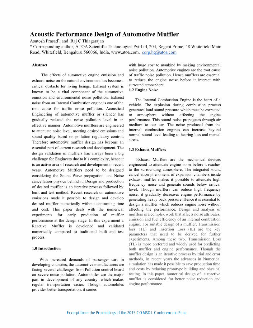
Figure 1. CAD Model of Automotive Muffler 2.2 Meshing
Meshing is defined as a process to discretize an
infinite geometric domain into finite numbers of elements and nodes. In this investigation the tetrahedral mesh elements are used. The maximum element length is calculated considering the wavenumber and wavelength. For Finite Element Analysis it is necessary to maintain four elements per each wavelength. Wavelength calculation
λ = fc
Where = Wavelength of Sound λ
c = Velocity of Sound = 343 m/sec f = Maximum Frequency = 2000 Hz
.1715 mλ = 343
2000 = 0 According to theory, there has to be four elements per wavelength Maximum element length
m.0428754Wavelength = 4
0.1715 = 0 = 42.875 mm
Excerpt from the Proceedings of the 2015 COMSOL Conference in Pune
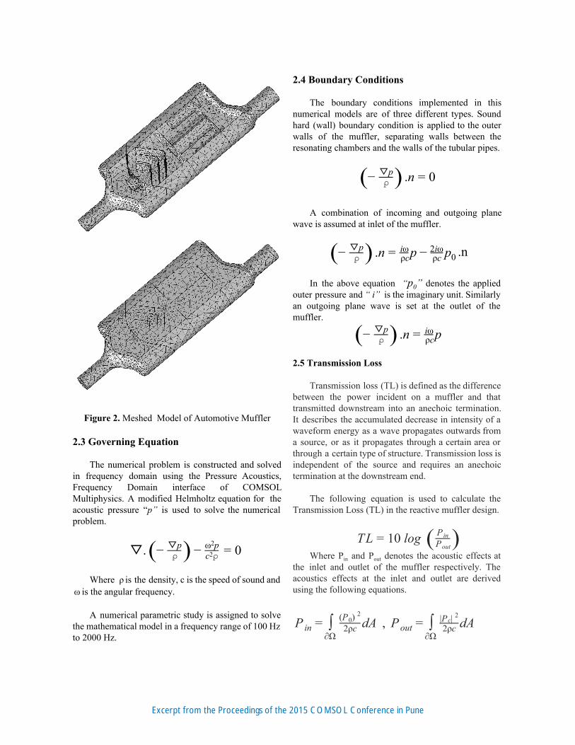
Figure 2. Meshed Model of Automotive Muffler
2.3 Governing Equation
The numerical problem is constructed and solved in frequency domain using the Pressure Acoustics, Frequency Domain interface of COMSOL Multiphysics. A modified Helmholtz equation for the acoustic pressure “p” is used to solve the numerical problem.
. ▽ −( ⍴▽p) − c ⍴2
ω p2 = 0
Where is the density, c is the speed of sound and ρ is the angular frequency.ω
A numerical parametric study is assigned to solve
the mathematical model in a frequency range of 100 Hz to 2000 Hz.
2.4 Boundary Conditions The boundary conditions implemented in this
numerical models are of three different types. Sound hard (wall) boundary condition is applied to the outer walls of the muffler, separating walls between the resonating chambers and the walls of the tubular pipes.
n −( ⍴▽p) . = 0
A combination of incoming and outgoing plane
wave is assumed at inlet of the muffler.
.nn p p −( ⍴▽p) . = ρc
iω − ρc2iω
0 In the above equation “p0” denotes the applied
outer pressure and“ i” is the imaginary unit. Similarly an outgoing plane wave is set at the outlet of the muffler.
n p −( ⍴▽p) . = ρc
iω
2.5 Transmission Loss Transmission loss (TL) is defined as the difference
between the power incident on a muffler and that transmitted downstream into an anechoic termination. It describes the accumulated decrease in intensity of a waveform energy as a wave propagates outwards from a source, or as it propagates through a certain area or through a certain type of structure. Transmission loss is independent of the source and requires an anechoic termination at the downstream end.
The following equation is used to calculate the
Transmission Loss (TL) in the reactive muffler design.
L 0 log T = 1 ( P inPout) Where Pin and Pout denotes the acoustic effects at
the inlet and outlet of the muffler respectively. The acoustics effects at the inlet and outlet are derived using the following equations.
, dAP in = ∫
∂Ω2ρc(P ) 0
2
dAP out = ∫
∂Ω2ρcP | c| 2
Excerpt from the Proceedings of the 2015 COMSOL Conference in Pune
3.0 Result & Discussion The performance of the reactive muffler design is
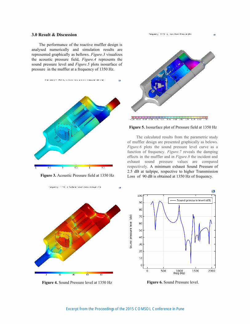
analysed numerically and simulation results are represented graphically as bellows. Figure.3 visualizes the acoustic pressure field, Figure.4 represents the sound pressure level and Figure.5 plots isosurface of pressure in the muffler at a frequency of 1350 Hz.
Figure 3. Acoustic Pressure field at 1350 Hz
Figure 4. Sound Pressure level at 1350 Hz
Figure 5. Isosurface plot of Pressure field at 1350 Hz
The calculated results from the parametric study of muffler design are presented graphically as belows. Figure.6 plots the sound pressure level curve as a function of frequency. Figure.7 reveals the damping effects in the muffler and in Figure.8 the incident and exhaust sound pressure values are compared respectively. A minimum exhaust Sound Pressure of 2.5 dB at tailpipe, respective to higher Transmission Loss of 90 dB is obtained at 1350 Hz of frequency.
Figure 6. Sound Pressure level.
Excerpt from the Proceedings of the 2015 COMSOL Conference in Pune

Figure 7. Transmission Loss (TL).
Figure 8. Sound Pressure level comparison. 4.0 Conclusions
In this experiment the performance of a reactive muffler model is analysed numerically. The numerical modelling methodology helped us to predict performance of a complex muffler design without traditional built and test methods. Muffler performance investigation by numerical methodologies shows potential to increase productivity of muffler manufacturers , reduces the production time and
cost respectively. Numbers of muffler can be designed and performance calculations can be performed in virtual environment before physical production. The numerical model can further be used to optimize mufflerdesign, for extreme sound cancellation and high engine performance in automobiles. 5.0 Acknowledgement
This research was supported by R & I Department of ATOA Scientific Technologies, Bengaluru, India. The author would like to thank the technical team,who provided insight and expertise that greatly assisted the research. 6.0 References [1] M,L. Munjal, Acoustic of Ducts and mufflers, New York:WileyInterscience(1986) [2] J. Igarashi and M.Toyama 1958 Aeronautical Research Institute, University of Tokyo, Report no.339, 223241 Fundamental of acoustical silencers [3] Shital Shah, et al., “A Practical Approach towards Muffler Design, Development and Prototype Validation”, SAE International, vol. 021, pp. 116, 2010. [4] Paritosh Bhattacharya, et al., “Design of Reactive Muffler for Study on the Noise Level and Performance of a Two cylinder Four Stroke 16 H.P Diesel Engine”, 2013. [5] Sabry Allam, “Acoustic Modeling and Testing of Advanced Exhaust System components for Automotive Engines”, Doctoral thesis, KTH, Sweden, 2004.
Excerpt from the Proceedings of the 2015 COMSOL Conference in Pune

Excerpt from the Proceedings of the 2015 COMSOL Conference in Pune