acoustic trilateration search and rescue using swarm robotics · 2016-04-28 · the swarm search...
TRANSCRIPT
Project ID: MXC-0421
Acoustic Trilateration Search andRescue Using Swarm Robotics
A Major Qualifying ProjectSubmitted to the Faculty of
Worcester Polytechnic Institutein partial fulfillment of the requirements for the
Degree in Bachelor of Sciencein
Computer Science and Robotics EngineeringBy
Corey AdayNidhi Diwakar
Dan Murray
Date: April 28, 2016Project Advisor:
Professor Michael Ciaraldi

AbstractThe goal of the project is to design and build a robotic system able to locate a sound sourcevia trilateration between multiple mobile robots on the same field, overseen by a mastercontroller. As they navigate the test environment, these robots will demonstrate time dif-ference of arrival (TDOA)-based localization and communication over a wireless network.Although previous research has proven that sound localization is possible on a mobile plat-form, this concept has not yet been shown for multiple mobile units that must communicatebetween each other. The intended application of this system is to model robot-aided search-and-rescue or underwater sound mapping.
i

Contents1. Introduction 1
1.1. Project Background . . . . . . . . . . . . . . . . . . . . . . . . . . . . . . . 11.2. Application . . . . . . . . . . . . . . . . . . . . . . . . . . . . . . . . . . . 31.3. Trilateration Concept . . . . . . . . . . . . . . . . . . . . . . . . . . . . . . 3
2. Methodology 52.1. Mechanical Design . . . . . . . . . . . . . . . . . . . . . . . . . . . . . . . 52.2. Parts Used . . . . . . . . . . . . . . . . . . . . . . . . . . . . . . . . . . . . 6
2.2.1. Motors . . . . . . . . . . . . . . . . . . . . . . . . . . . . . . . . . 62.2.2. Wheels and Casters . . . . . . . . . . . . . . . . . . . . . . . . . . . 62.2.3. Power Sources . . . . . . . . . . . . . . . . . . . . . . . . . . . . . 72.2.4. Microphone . . . . . . . . . . . . . . . . . . . . . . . . . . . . . . . 72.2.5. CPUs . . . . . . . . . . . . . . . . . . . . . . . . . . . . . . . . . . 82.2.6. Chassis Components . . . . . . . . . . . . . . . . . . . . . . . . . . 8
2.3. Electronic Design . . . . . . . . . . . . . . . . . . . . . . . . . . . . . . . . 82.4. Software Design . . . . . . . . . . . . . . . . . . . . . . . . . . . . . . . . . 10
2.4.1. Program Flow . . . . . . . . . . . . . . . . . . . . . . . . . . . . . . 112.5. Costs Summary . . . . . . . . . . . . . . . . . . . . . . . . . . . . . . . . . 12
3. Results 143.1. Assessment Criteria . . . . . . . . . . . . . . . . . . . . . . . . . . . . . . . 14
4. Discussion 15
5. Conclusions 17
6. Future Works 18
A. Appendix A 20A.1. ADC Datasheet . . . . . . . . . . . . . . . . . . . . . . . . . . . . . . . . . 20A.2. Digital Pot Datasheet . . . . . . . . . . . . . . . . . . . . . . . . . . . . . . 21A.3. Microphone Datasheet . . . . . . . . . . . . . . . . . . . . . . . . . . . . . 22A.4. Thin Speaker Datasheet . . . . . . . . . . . . . . . . . . . . . . . . . . . . . 23
ii

List of Figures1. Microphone Array and Robot [1] . . . . . . . . . . . . . . . . . . . . . . . . 12. Ultrasonic Sensor Configuration [2] . . . . . . . . . . . . . . . . . . . . . . 23. Sound Direction Localization Using Binaural Sensing [3] . . . . . . . . . . . 24. Trilateration Diagram . . . . . . . . . . . . . . . . . . . . . . . . . . . . . . 35. One Field Robot . . . . . . . . . . . . . . . . . . . . . . . . . . . . . . . . . 56. MCP3008 Connected to Pi Cobbler [4] . . . . . . . . . . . . . . . . . . . . . 97. Electronics Configuration between Master and Swarm Unit . . . . . . . . . . 108. Beacon Amplifier Circuit (Circuit Basics, Fritzing) . . . . . . . . . . . . . . 109. Program Flow Graphic . . . . . . . . . . . . . . . . . . . . . . . . . . . . . 1110. Final Chassis Design . . . . . . . . . . . . . . . . . . . . . . . . . . . . . . 15
iii

List of Tables1. Cost Evaluation . . . . . . . . . . . . . . . . . . . . . . . . . . . . . . . . . 13
iv
1. IntroductionThis robotic system was designed to locate a sound source via trilateration between multiplemobile robots on the same field. As they navigated the test environment, these robots aimedto demonstrate time difference of arrival (TDOA)- based localization and mapping over awireless network. Each robot was equipped with a single microphone and processing units,as well as wheels and encoders for navigation. Upon hearing the sound source, each robotwas designed to report wirelessly to the master, which was tasked with making calculationsto determine where the source was located. With this information, the master was designedto dispatch the robots to find the source, allowing the robots to navigate to their assignedlocations.
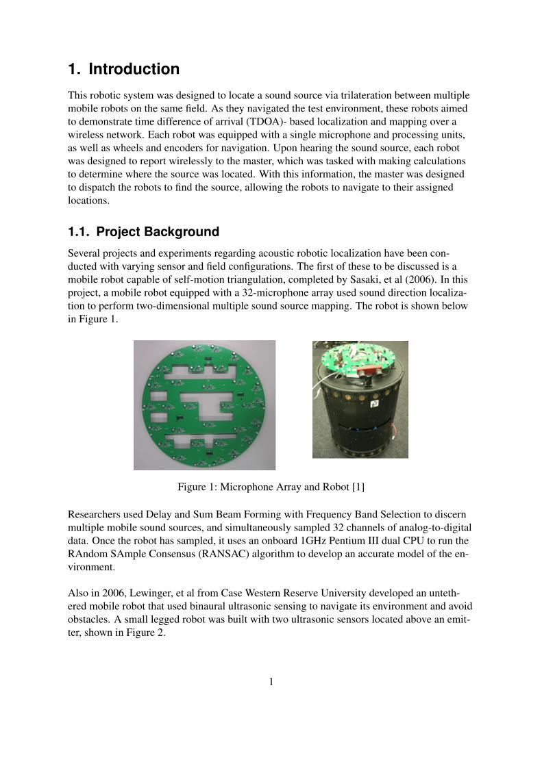
1.1. Project BackgroundSeveral projects and experiments regarding acoustic robotic localization have been con-ducted with varying sensor and field configurations. The first of these to be discussed is amobile robot capable of self-motion triangulation, completed by Sasaki, et al (2006). In thisproject, a mobile robot equipped with a 32-microphone array used sound direction localiza-tion to perform two-dimensional multiple sound source mapping. The robot is shown belowin Figure 1.
Figure 1: Microphone Array and Robot [1]
Researchers used Delay and Sum Beam Forming with Frequency Band Selection to discernmultiple mobile sound sources, and simultaneously sampled 32 channels of analog-to-digitaldata. Once the robot has sampled, it uses an onboard 1GHz Pentium III dual CPU to run theRAndom SAmple Consensus (RANSAC) algorithm to develop an accurate model of the en-vironment.
Also in 2006, Lewinger, et al from Case Western Reserve University developed an unteth-ered mobile robot that used binaural ultrasonic sensing to navigate its environment and avoidobstacles. A small legged robot was built with two ultrasonic sensors located above an emit-ter, shown in Figure 2.
1

Figure 2: Ultrasonic Sensor Configuration [2]
By analyzing the differences of sound intensity received at each sensor, the team was ableto execute obstacle detection and avoidance behaviors in an experimental field. This projectused an Acroname Brainstem microcontroller to process signals from the ultrasonic sensorsas well as R/C commands sent from operators on the field.
A third group of researchers Murray, et al, explored the concept of interaural time differ-ence analysis on a mobile robot equipped with two microphones, similar to the configurationof mammalian ears (2004). This robot was designed as a waiter listening for customers ina busy restaurant, so the experimental field included multiple, distinct sound sources. Thisconcept is displayed in Figure 3.
Figure 3: Sound Direction Localization Using Binaural Sensing [3]
To properly detect and localize sound, these researchers used principles present in the mam-malian auditory cortex, such as interaural time difference and interaural phase difference.The robot used several high-speed processing units to gather and compute acoustic data withrespect to azimuth.
While all of this research proves that sound localization is possible on a mobile platform,this concept has not yet been shown for multiple individually mobile platforms that mustcommunicate between each other. The intended application of this system is to model robot-aided search-and-rescue. In this circumstance, the target that must be sought and rescued
2
would have a sound-emitting device which would be activated as necessary. Adjustments tothe propagation characteristics and communication would be made to allow for environmen-tal shifts.
1.2. ApplicationThe swarm search and rescue can be implemented in a setting where a hiker is lost and re-quires assistance. The units would patrol well-known hiking areas, and each hiker wouldcarry a sound-emitting device. If the hiker was lost or injured, he or she would activate theirbeacon. Upon hearing the beacon, the swarm units would begin the cycle of listening andsearching for the source.
The concept in this project can also be applied to the real world issue of aquatic animal track-ing, where whales and dolphins make loud, distinguishable sounds. Each swarm unit wouldbe dispatched in the water, and would either anchor to the seafloor or dwell at a constantdepth while sensing. They would surface to determine their locations via GPS, and this pro-cess would be used to find creatures underwater. Naturally, it would be necessary to includealtitude detection in this context.
1.3. Trilateration Concept
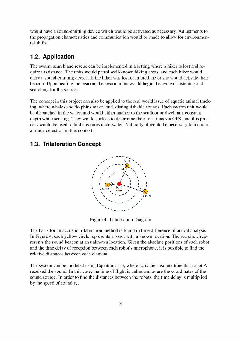
Figure 4: Trilateration Diagram
The basis for an acoustic trilateration method is found in time difference of arrival analysis.In Figure 4, each yellow circle represents a robot with a known location. The red circle rep-resents the sound beacon at an unknown location. Given the absolute positions of each robotand the time delay of reception between each robot’s microphone, it is possible to find therelative distances between each element.
The system can be modeled using Equations 1-3, where as is the absolute time that robot Areceived the sound. In this case, the time of flight is unknown, as are the coordinates of thesound source. In order to find the distances between the robots, the time delay is multipliedby the speed of sound vs.
3

da = asvs (1)
∆db = bsvs (2)
∆dc = csvs (3)
Where bs and cs are measured relative to as. Using simple distance formulas, we find Equa-tions 4-6, a nonlinear system of equations which can then be condensed into a solvable, lin-ear system.
(xs − ax)2 + (ys − ay)2 = d2a (4)
(xs − bx)2 + (ys − by)2 = (da + ∆db)
2 (5)
(xs − cx)2 + (ys − cy)2 = (da + ∆dc)
2 (6)
4

2. Methodology
2.1. Mechanical DesignThe robot is designed with three main levels and a smaller fourth level, as seen in Figure 5below.
Figure 5: One Field Robot
Starting at the bottom, the first layer contains the components necessary for movement. Themotors, wheels, and casters are all attached to this level. The second level holds the powerbanks, putting them in the middle of the robot. This keeps the center of gravity relativelylow, as well as putting the power sources in a central location that is easy to reach for allcomponents.
The third level holds both microcontrollers, situated right next to the small fourth level,which holds the circuitry and the sound detector. Having the sound detector at the very topof the robot minimized the chances of noise interference from the robot’s own components,including the motors at the very base of the robot.
Prior to this design, a prototype with a slightly different design was built for testing pur-poses. The prototype had only two levels, and was half again the diameter of the final design.The prototype also used two omniwheels in place of the casters in the final design. Although
5
the design was functional, it was too wide for the purposes of this project while still not hav-ing enough space for two microcontrollers and all three power banks. In addition, the noisefrom the motors interfered with the sound detector.
2.2. Parts Used2.2.1. Motors
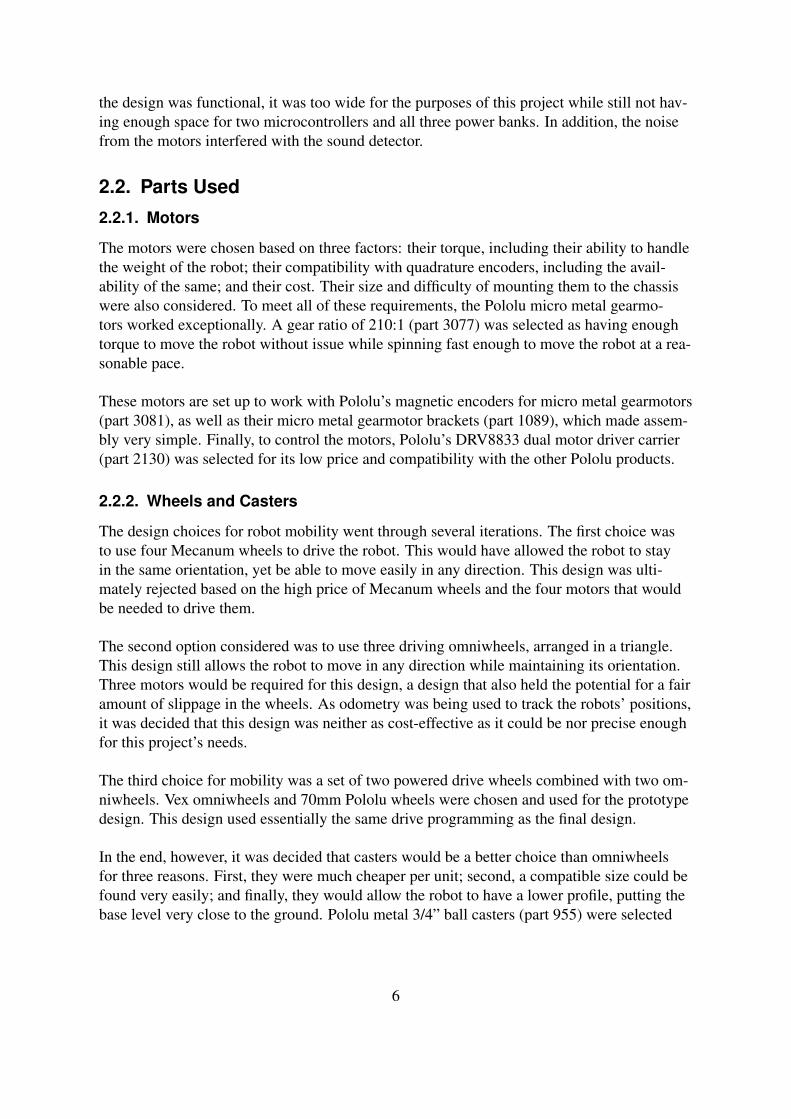
The motors were chosen based on three factors: their torque, including their ability to handlethe weight of the robot; their compatibility with quadrature encoders, including the avail-ability of the same; and their cost. Their size and difficulty of mounting them to the chassiswere also considered. To meet all of these requirements, the Pololu micro metal gearmo-tors worked exceptionally. A gear ratio of 210:1 (part 3077) was selected as having enoughtorque to move the robot without issue while spinning fast enough to move the robot at a rea-sonable pace.
These motors are set up to work with Pololu’s magnetic encoders for micro metal gearmotors(part 3081), as well as their micro metal gearmotor brackets (part 1089), which made assem-bly very simple. Finally, to control the motors, Pololu’s DRV8833 dual motor driver carrier(part 2130) was selected for its low price and compatibility with the other Pololu products.
2.2.2. Wheels and Casters
The design choices for robot mobility went through several iterations. The first choice wasto use four Mecanum wheels to drive the robot. This would have allowed the robot to stayin the same orientation, yet be able to move easily in any direction. This design was ulti-mately rejected based on the high price of Mecanum wheels and the four motors that wouldbe needed to drive them.
The second option considered was to use three driving omniwheels, arranged in a triangle.This design still allows the robot to move in any direction while maintaining its orientation.Three motors would be required for this design, a design that also held the potential for a fairamount of slippage in the wheels. As odometry was being used to track the robots’ positions,it was decided that this design was neither as cost-effective as it could be nor precise enoughfor this project’s needs.
The third choice for mobility was a set of two powered drive wheels combined with two om-niwheels. Vex omniwheels and 70mm Pololu wheels were chosen and used for the prototypedesign. This design used essentially the same drive programming as the final design.
In the end, however, it was decided that casters would be a better choice than omniwheelsfor three reasons. First, they were much cheaper per unit; second, a compatible size could befound very easily; and finally, they would allow the robot to have a lower profile, putting thebase level very close to the ground. Pololu metal 3/4” ball casters (part 955) were selected
6

for their height and load-bearing capacity. To complement them, a set of two 32mm Pololuwheels (part 1087), designed to be used with the micro gearmotors mentioned above, wereused as drive wheels.
2.2.3. Power Sources
In the original design, the robot would have been run off of a single power source, around9volts with a preferably high amperage and capacity. The first choice was a LiPo battery,for their low cost and small size; this idea was discarded based on the difficulty of charg-ing LiPo batteries, as well as the availability of large capacities. However, as the designs be-came more final, it was clear that a single power source would not meet the needs of eachseparate section. The motors would require their own power source due to the heavy currentdraw, as would the sound-sensing chip, which needed a more specific voltage. The micro-controllers would need yet another power source to ensure that they both received a steadyflow of power at the correct voltage. A steady flow of power was most important for the mi-crocontrollers, so the most steady power source would need to be used for them.
With this in mind, a cell phone battery charger pack was selected to power the microcon-trollers. This choice was made for several reasons, including the relative steadiness of apower source meant to be used as a charger. It was also compact, high capacity, and low-cost. A two-port 10AH phone charger pack was selected so that both microcontrollers couldbe connected at once without bringing in yet another power source.
For the motors, two 3.7V 18650 batteries were placed in series, giving the motors the sevenvolts required for movement. As 18650 batteries are commonly used in flashlights, head-lamps, and similar light sources, they were readily available, and were inexpensive whencompared to dedicated motor batteries. For the sound sensing chip, three AAA batteries wereplaced in series. This satisfied the power requirements in a very low-cost and easily replace-able way.
2.2.4. Microphone
The first choice of design was to use a regular omnidirectional microphone and filter thenoises both digitally and mechanically. This proved to add a level of complexity that thedesign could not accommodate. Instead, the SparkFun sound detector (part 12642) was se-lected. The sound detector was an audio sensing board that provides three different outputs:audio, a binary signal of the presence or non-presence of sound, and an analog signal rep-resenting its amplitude. Although a greater cost than a small omnidirectional microphonealone, this chip allowed for greater flexibility in filtering the sounds to find the signal therobot was searching for.
7

2.2.5. CPUs
The microcontroller used for this project had a very strict set of requirements to fulfill. First,it needed a processor speed of at least 100MHz to be able to detect the sound signal withenough precision to make an accurate TDOA calculation. Second, it needed to be able tocontrol the motors; third, it needed to be able to read the encoders. It also needed to supporta Wi-Fi connection and handle multi-threaded processing. Finally, it needed to be compatiblewith the sound detector.
With these six requirements in mind, the Beaglebone Black was selected. In theory, thisboard should have had the capacity to meet each requirement. However, the board was unre-liable, poorly documented, and difficult to use. It is still unknown whether the individual unitthe team had access to for the prototype was simply faulty or if all iterations of this boardwould have had the same issue. Unfortunately, a second unit was not available to test this,and a new microcontroller had to be selected in the end.
However, no other low-cost microcontroller was able to meet the specific requirements of theproject alone; therefore, it was decided that two microcontrollers would be used in tandem.The Raspberry Pi 2 B, combined with a Pi Cobbler (an extension to the Pi that allows forextra functions), had enough processing speed and power to handle the sound detector aswell as Wi-Fi, while the Arduino Uno could easily control the motors and read the encoders.The two microcontrollers could be connected and communicate via USB.
2.2.6. Chassis Components
Each level of each robot was laser-cut from .125” cast acrylic sheets. Wood of a similarthickness was also considered, as it would also be easy to laser-cut and is actually less ex-pensive than the acrylic. However, acrylic was chosen for several reasons. The surface ofthe acrylic is smoother, making it easier to attach things like Velcro. Acrylic is tough enoughto handle the amount of strain that these robots are under—they are fairly light-weight ma-chines, and no single sheet of acrylic is any longer than 8 inches across, not long enough tobuckle for lack of support. Finally, the acrylic is transparent, which makes it easier to tracewires and other components through the design while building and redesigning.
Vex brand 8x32 hex standoffs combined with 3/8” 8x32 screws separate the layers, leavingspace in each layer to move the components if necessary. Velcro strips are used to attach thepower banks and breadboards to the chassis, making them easy to detach or move around.The chassis altogether is relatively small and lightweight, considering the number of compo-nents and potential battery life.
2.3. Electronic DesignFor this application, the team originally chose the BeagleBone Black microcontroller andupon finding multiple functional defects, switched to a Raspberry Pi/Arduino combination.
8

With the latter configuration, each swarm unit used a Raspberry Pi to sense sound and com-municate wirelessly with the master computer. Each unit also contained an Arduino, whichreceived motor commands from the Raspberry Pi.
The Raspberry Pi offers WiFi capabilities, forty input/output pins, an HDMI port, four USBports, an Ethernet port, and a clock speed of 900 MHz. While it does not offer an onboardanalog to digital converter (ADC), there exists a Pi Cobbler breakout board, which providesaccess to all of the pins on the Pi board, and easily connects to the MCP3008. The MCP3008is an 8-channel ADC with 10-bit resolution and a maximum sampling capacity of 200 kilo-samples per second. Figure 6 shows the MCP3008 connected to the Cobbler with a poten-tiometer for testing purposes.
Figure 6: MCP3008 Connected to Pi Cobbler [4]
To sense the beacon, the team chose the SEN 12642 sound detector from Sparkfun. Thisparticular module was chosen for its three outputs: a binary representation of the presenceof sound, an amplitude representation of the wave, and an analog representation of the fullwave form. This varied functionality gave each robot more flexibility when processing thesignal and this affected the method of software analysis as well. To control sensitivity atvarying distances and to properly account for the variation in ambient noise level, the teamutilized an MCP4131 digital potentiometer. This allowed the capability to control the gain ofthe microphone through software via I2C. A top-level view of this configuration can be seenin Figure 7.
The team used a WiFi adapter with the Raspberry Pi to communicate with the master com-puter. To control motion, an Arduino Uno was connected to the Pi via USB. This board isequipped with six PWM-enabled I/O pins, multiple ADC pins, and a USB port. Throughoutthe trilateration process, the master would send motor commands wirelessly to the Pi, whichwould pass on the information to the Arduino over USB. The Arduino sent PWM signals toa DRV8833 dual motor driver, which controlled two DC motors equipped with two encoders.Each encoder fed into an I/O interrupt pin of the Arduino.
The beacon for this project was a thin speaker attached to an amplifier. An Arduino Mini wasdesigned to provide a square wave at 5 KHz. Figure 8 shows the amplifier set up.
9

Figure 7: Electronics Configuration between Master and Swarm Unit
Figure 8: Beacon Amplifier Circuit (Circuit Basics, Fritzing)
2.4. Software DesignThe general layout of the software underlying the project was designed to be modular andstraightforward. There was a section of the program to be run on the master, a section to berun on each swarm robot, and a section to be run on the beacon. The master was in charge of
10
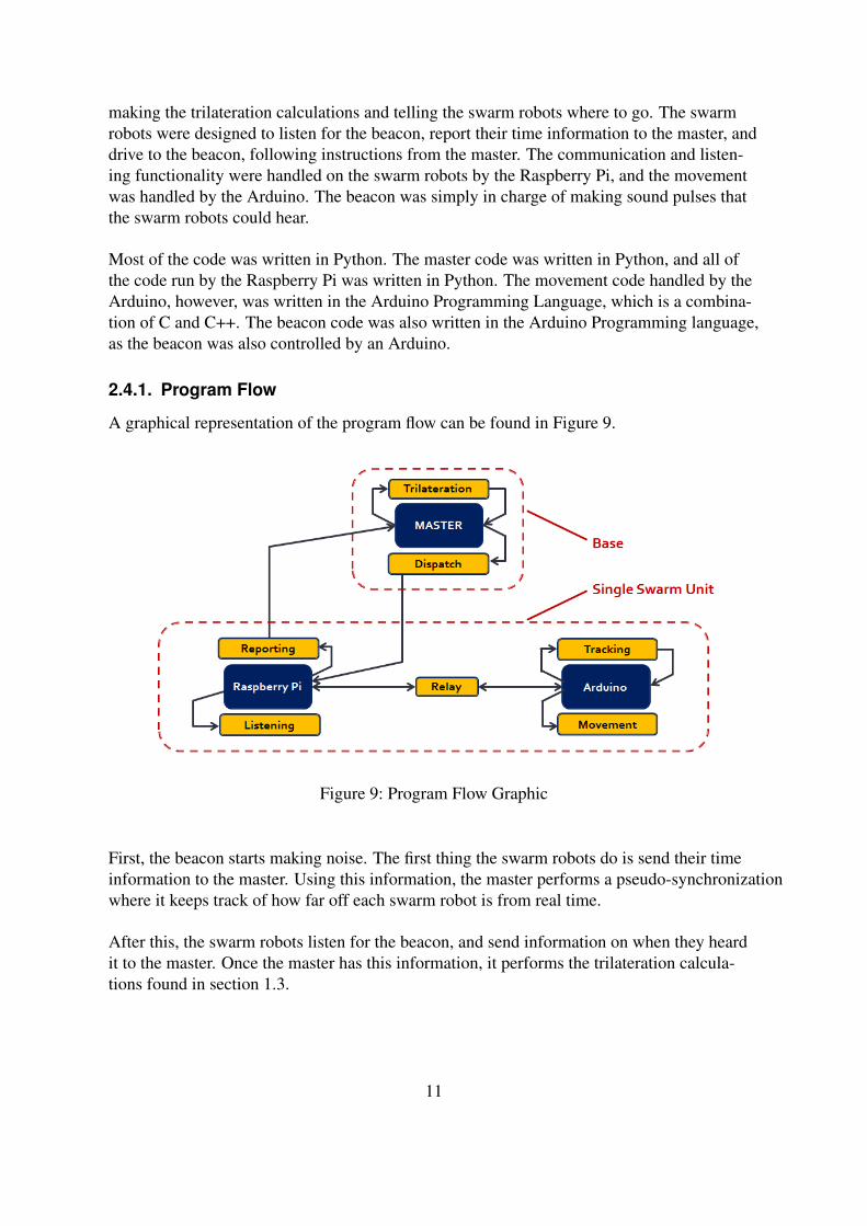
making the trilateration calculations and telling the swarm robots where to go. The swarmrobots were designed to listen for the beacon, report their time information to the master, anddrive to the beacon, following instructions from the master. The communication and listen-ing functionality were handled on the swarm robots by the Raspberry Pi, and the movementwas handled by the Arduino. The beacon was simply in charge of making sound pulses thatthe swarm robots could hear.
Most of the code was written in Python. The master code was written in Python, and all ofthe code run by the Raspberry Pi was written in Python. The movement code handled by theArduino, however, was written in the Arduino Programming Language, which is a combina-tion of C and C++. The beacon code was also written in the Arduino Programming language,as the beacon was also controlled by an Arduino.
2.4.1. Program Flow
A graphical representation of the program flow can be found in Figure 9.
Figure 9: Program Flow Graphic
First, the beacon starts making noise. The first thing the swarm robots do is send their timeinformation to the master. Using this information, the master performs a pseudo-synchronizationwhere it keeps track of how far off each swarm robot is from real time.
After this, the swarm robots listen for the beacon, and send information on when they heardit to the master. Once the master has this information, it performs the trilateration calcula-tions found in section 1.3.
11

Once the master has determined the position of the beacon with respect to the positions ofthe robots, it sends movement commands to each of the swarm robots.
The robots receive these commands and execute them, using the encoders on their motors todetermine how far they have moved in a given direction. Once the master has finished giv-ing movement commands to the swarm robots, it sends a message signifying the end of theprogram.
Threading was a key component in this project. The swarm robots each had two threadsin their program: one thread to communicate with the master and receive movement com-mands, and one thread to execute the commands using the motors and encoders. The masterhad one thread for each of the robots, so that the movements of the robots could occur simul-taneously instead of one-at-a-time.
2.5. Costs SummaryTable 1 below contains a detailed breakdown of costs for each robot.
According to Table 1, the total cost per robot is approximately $249.43. Comparably sizedrobots cost between $250 and $350, and do not usually have sound-sensing systems or theversatility of two microcontrollers that this design has.
12

Part Cost Number/Robot Total Cost/RobotBarrel Jack to USB Connector 1.88 1 1.88USB A to USB B Connector 5.99 1 5.99
Raspberry Pi 39.95 1 39.95Raspberry Pi Cobbler 6.95 1 6.95
Arduino Uno 24.95 1 24.95ADC 3.75 1 3.75
Micro SD Card (for Raspberry Pi) 11.99 1 11.99AAA Battery Case 1.95 1 1.95
AAA Batteries 2.50 1 2.50Micro Gearmotor 18.95 2 37.90
Magnetic Motor Quadrature Encoder 8.95 1 8.95Dual Motor Driver 4.95 1 4.95
Motor Brackets 4.99 1 4.991/8x12x24” Acrylic Sheet 12.99 1 12.99
Cell Phone Battery/Charger 9.99 1 9.99WiFi Adaptor 9.99 1 9.99
18650 Batteries 9.50 1 9.5018650 Battery Case 1.50 1 1.50
Sound Detector 10.95 1 10.95Solderless Bread Boards 7.69 1 7.69
Jumper Wires 5.99 1 5.99Vex Standoffs 12.50 1 12.50
Digital Potentiometer 0.67 1 0.67Wheels 4.98 1 4.98Casters 2.99 2 5.98
Table 1: Cost Evaluation
13
3. Results
3.1. Assessment CriteriaThere are several criteria the project was judged by. The robots themselves were judgedbased on their cost, abilities, and connectivity. The robots needed to be low-cost, be able toidentify sounds and record their times of arrival, and communicate with the master.
For the trilateration, another set of criteria was used. These include accuracy, execution time,rate of success, and feasibility. Accuracy was judged by how close the robots could calculatethe location of the sound beacon compared to its actual location. The calculated error wasapproximately 7cm, assuming that the processors had error of approximately 200 nanosec-onds, with a field size of approximately six meters square. Execution time was judged basedon how long the robots took to find the beacon (or to find the spot they assumed the beaconwas located), and rate of success was based on how many times the robots found the beacon(within acceptable error) out of the times the trials were run.
The final criteria, feasibility, includes the potential for future work. Some possible factors forusefulness include the length of the battery life, the accuracy of the program (as discussedabove), and what changes might be made to adapt it to a new environment.
14
4. DiscussionDuring the course of the project, the team encountered many technical challenges, someof which hindered progress. The first of these was the choice of microcontroller. To prop-erly sense and trilaterate, it was essential to have a microcontroller with an ADC built in ormodular with a sufficient clock speed. Since the robots are also mobile, the team initiallychose the BeagleBone Black. This board has features of both an Arduino and RaspberryPi.However, documentation on its use is heavily lacking, and frequently, the team was unableto communicate with its GPIO pins, connect to the internet, or even upload any code to theboard. It was after much deliberation and effort that the team switched to the RaspberryPi/Arduino combination. This choice was much more functional, as both boards are wellknown and come with technical support. The interface between the user and the board is alsoconsiderably more intuitive and well adapted to various applications.
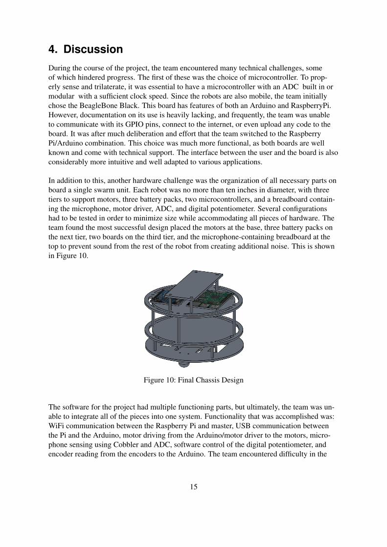
In addition to this, another hardware challenge was the organization of all necessary parts onboard a single swarm unit. Each robot was no more than ten inches in diameter, with threetiers to support motors, three battery packs, two microcontrollers, and a breadboard contain-ing the microphone, motor driver, ADC, and digital potentiometer. Several configurationshad to be tested in order to minimize size while accommodating all pieces of hardware. Theteam found the most successful design placed the motors at the base, three battery packs onthe next tier, two boards on the third tier, and the microphone-containing breadboard at thetop to prevent sound from the rest of the robot from creating additional noise. This is shownin Figure 10.
Figure 10: Final Chassis Design
The software for the project had multiple functioning parts, but ultimately, the team was un-able to integrate all of the pieces into one system. Functionality that was accomplished was:WiFi communication between the Raspberry Pi and master, USB communication betweenthe Pi and the Arduino, motor driving from the Arduino/motor driver to the motors, micro-phone sensing using Cobbler and ADC, software control of the digital potentiometer, andencoder reading from the encoders to the Arduino. The team encountered difficulty in the
15

process of multithreading with Python and debugging through the layer of abstraction thatPython presents as a language. It is also uncertain how robust the microphone sensing is withrespect to the environment, as the maximum sensitivity with the software-controlled poten-tiometer was half of the original sensitivity on the manufactured microphone. Due to this, thesound from the beacon had to be much louder than our design could support.
The final aspect of our design that required improvement was the beacon. It was designed toamplify a signal from an Arduino Uno or Mini board. However, the team found several is-sues with the wave generation feature of the Arduino. It was only possible to output a squarewave from the Arduino, which directly conflicted with the specifications on most speakers,which are easily capable of producing a clean 15kHz when given sine waves. In addition,due to the slow standard clock speed available on standard PWM pins, the Arduino was un-able to match any high frequency as the PWM operational frequency is only roughly 500 Hz.When the team attempted to use the Tone library, which is capable of 65.535 kHz, ringingand rattling could be heard from the speaker despite the documentation clearly stating that itshould not pose a problem. The team also implemented a single transistor between the Ar-duino and speaker, and while this provided the same intensity of sound, it was not possible toincrease the amplitude for the distance that was required.
16
5. ConclusionsFrom this project, the team gained a great understanding of the complexity of signal pro-cessing with sound in the audible range. Many factors must be considered, including scale,accuracy of hardware, and robustness of detection. It was found that it is theoretically possi-ble to use swarm units to trilaterate a sound in an environment. However, this work requireshigh processing power and statistical analysis, as well as adjustments in mechanical designfor real world environments. It is also necessary to repeatedly test the reliability of this sys-tem and carefully calculate the error, as this changes with the nature of the environment andthe motion capabilities of the robots themselves. Overall, this project has strong potential tobe implemented underwater, and the dynamics of sound would be worthwhile to study.
17

6. Future WorksThe initial design of this project included multiple phases. Through the course of the project,work was only done in phase 1. Upon completion of phase 1, the robots would be able tohear the beacon, send their information to the master, receive commands to move to the bea-con, and monitor their motion using only their own encoders. For the sake of future work,the following is a high-level layout of the remaining phases.
Phase 2 would see the addition of a second master computer, as well as each swarm robotreceiving its own beacon with its own unique sound signature. This way, the robots wouldstill monitor their motion using their own encoders, but after they believe they have reachedthe beacon, they would then sound off their own beacons. The two master computers wouldthen perform a modified trilateration process to locate each of the robots, the robots wouldlisten for the goal beacon again, and the whole process would repeat until the robots reachedthe goal beacon. Phase 2 accounts for any slipping that may occur, which the motor encoderswouldn’t report.
After phase 2 was complete, phase 3 would institute a system where the robots were contin-uously sounding off their beacons, and their motion would be exclusively monitored by thetwo masters’ modified trilateration technique. This way, the program would only have to berun through a single time.
In phase 4, obstacles in the field would be introduced. The field would be known to the mas-ter computers, and they would be in charge of path planning for the swarm robots.
18

References[1] M. H. Sasaki Y, Kagami S, “Multiple sound source mapping for a mobile robot by self-
motion triangulation,” 2009, in: IEEE international conference on intelligent robots andsystems, pp 380-385.
[2] R. D. Q. William A Lewinger, Michael S Watson, “Obstacle avoidance behavior for abiologically-inspired mobile robot using binaural ultrasonic sensors,” 2006, iEEE/RSJInternational Conference on Intelligent Robots and Systems, p. 5769-5774, Beijing,China.
[3] W. S. Murray JC, Erwin HR, “Robotic sound-source localization and tracking using in-teraural time difference and cross-correlation,” 2004, aI Workshop on Neurobotics.
[4] “Build a great sounding audio amplifier (with bass boost) from the lm386,” 2016, circuitBasics.
[5] C.-K. W. J.-S. Hu, C.-Y. Chan and C.-C. Wang, “Simultaneous localization of mobilerobot and multiple sound sources using microphone array,” 2009, in Proc. IEEE ICRA,Kobe, Japan, pp. 29-34.
[6] F. Keyrouz, “Efficient binaural sound localization for humanoid robots and telepresenceapplications,” 2008, (Ph.D. thesis), Technische Universitaat Munchen.
[7] F. C. Emmanuel Vincent, Aghilas Sini, “Audio source localization by control of a mo-bile robot,” 2015, iEEE 2015 International Conference on Acoustics, Speech and SignalProcessing (ICASSP), Brisbane, Australia.
19

© 2008 Microchip Technology Inc. DS21295D-page 1
MCP3004/3008
Features• 10-bit resolution• ± 1 LSB max DNL• ± 1 LSB max INL • 4 (MCP3004) or 8 (MCP3008) input channels• Analog inputs programmable as single-ended or
pseudo-differential pairs• On-chip sample and hold• SPI serial interface (modes 0,0 and 1,1)• Single supply operation: 2.7V - 5.5V• 200 ksps max. sampling rate at VDD = 5V• 75 ksps max. sampling rate at VDD = 2.7V• Low power CMOS technology• 5 nA typical standby current, 2 µA max.• 500 µA max. active current at 5V• Industrial temp range: -40°C to +85°C • Available in PDIP, SOIC and TSSOP packages
Applications• Sensor Interface• Process Control• Data Acquisition• Battery Operated Systems
Functional Block Diagram
DescriptionThe Microchip Technology Inc. MCP3004/3008devices are successive approximation 10-bit Analog-to-Digital (A/D) converters with on-board sample andhold circuitry. The MCP3004 is programmable toprovide two pseudo-differential input pairs or foursingle-ended inputs. The MCP3008 is programmableto provide four pseudo-differential input pairs or eightsingle-ended inputs. Differential Nonlinearity (DNL)and Integral Nonlinearity (INL) are specified at ±1 LSB.Communication with the devices is accomplished usinga simple serial interface compatible with the SPIprotocol. The devices are capable of conversion ratesof up to 200 ksps. The MCP3004/3008 devices operateover a broad voltage range (2.7V - 5.5V). Low-currentdesign permits operation with typical standby currentsof only 5 nA and typical active currents of 320 µA. TheMCP3004 is offered in 14-pin PDIP, 150 mil SOIC andTSSOP packages, while the MCP3008 is offered in 16-pin PDIP and SOIC packages.
Package Types
Comparator
Sampleand Hold
10-Bit SAR
DAC
Control Logic
CS/SHDN
VREF
VSSVDD
CLK DOUT
ShiftRegister
CH0
ChannelMax
InputCH1
CH7*
* Note: Channels 4-7 are available on MCP3008 Only
DIN
VDD
CLKDOUT
MC
P3004
1234
1413121110
98
567
VREF
DIN
CH0CH1CH2CH3
CS/SHDNDGND
AGND
NC
VDD
CLKDOUT
MC
P3008
1234
161514131211109
5678
VREF
DINCS/SHDNDGND
CH0CH1CH2CH3CH4CH5CH6CH7
NC
AGND
PDIP, SOIC, TSSOP
PDIP, SOIC
2.7V 4-Channel/8-Channel 10-Bit A/D Converterswith SPI Serial Interface
A. Appendix A
A.1. ADC Datasheet

© 2008 Microchip Technology Inc. DS22060B-page 1
MCP413X/415X/423X/425X
Features• Single or Dual Resistor Network options• Potentiometer or Rheostat configuration options• Resistor Network Resolution
- 7-bit: 128 Resistors (129 Steps)- 8-bit: 256 Resistors (257 Steps)
• RAB Resistances options of:- 5 kΩ - 10 kΩ - 50 kΩ - 100 kΩ
• Zero Scale to Full-Scale Wiper operation• Low Wiper Resistance: 75Ω (typical)• Low Tempco:
- Absolute (Rheostat): 50 ppm typical(0°C to 70°C)
- Ratiometric (Potentiometer): 15 ppm typical• SPI Serial Interface (10 MHz, modes 0,0 & 1,1)
- High-Speed Read/Writes to wiper registers- SDI/SDO multiplexing (MCP41X1 only)
• Resistor Network Terminal Disconnect Feature via:- Shutdown pin (SHDN) - Terminal Control (TCON) Register
• Brown-out reset protection (1.5V typical)• Serial Interface Inactive current (2.5 uA typical)• High-Voltage Tolerant Digital Inputs: Up to 12.5V• Supports Split Rail Applications • Internal weak pull-up on all digital inputs • Wide Operating Voltage:
- 2.7V to 5.5V - Device Characteristics Specified
- 1.8V to 5.5V - Device Operation• Wide Bandwidth (-3 dB) Operation:
- 2 MHz (typical) for 5.0 kΩ device • Extended temperature range (-40°C to +125°C)
DescriptionThe MCP41XX and MCP42XX devices offer a widerange of product offerings using an SPI interface. Thisfamily of devices support 7-bit and 8-bit resistornetworks, and Potentiometer and Rheostat pinouts.
Package Types (top view)
1234 5
678
P0WP0B
P0AVSS
VDD
MCP41X1 Single Potentiometer
PDIP, SOIC, MSOP
CS
SDI/SDOSCK
1234 5
678
P0BSDO
P0W
VDD
MCP41X2 Single Rheostat
PDIP, SOIC, MSOP
1234 11
121314
SHDNSDO
WP
VDD
MCP42X1 Dual Potentiometers
PDIP, SOIC, TSSOP
567 8
910
P0WP0B
P0AP1AP1WP1B
VSS
CS
SDISCK
VSS
CS
SDISCK
4x4 QFN*
1234 7
89
10SDOVDD
MCP42X2 Dual Rheostat
MSOP, DFN
5 6
P0BP0WP1WP1B
VSS
CS
SDISCK
3x3 DFN*
SDI/SDOSCK
VSS
P0B
P0W
1
2
34
8
7
65 P0A
CS
EP9
3x3 DFN*
SDI
SCK
VSS
SDO
P0B
1
2
34
8
7
65 P0W
VDDCS
EP9
VDD
3x3 DFN*
SDI
SCK
VSS
SDO
P0B
1
2
34
10
9
87 P0W
CS
EP11
VDD
5 6P1B P1W
* Includes Exposed Thermal Pad (EP); see Table 3-1.
2VSS
VSS
SCK WP
NC
P1B
P0B
P1W P1
A
P0A
P0W
CS
VD
D
SD
O
SH
DN
SDI EP
161
15 14 13
3
4
12
1110
95 6 7 8
17
7/8-Bit Single/Dual SPI Digital POT with Volatile Memory
A.2. Digital Pot Datasheet

Features at +2.7V• 80µA supply current per channel• 1.2MHz gain bandwidth product• Output voltage range: 0.01V to 2.69V• Input voltage range: -0.25V to +1.5V• 1.5V/µs slew rate• LMV321 directly replaces other industry standard LMV321
amplifiers; available in SC70-5 and SOT23-5 packages• LMV358 directly replaces other industry standard LMV358
amplifiers; available in MSOP-8 and SOIC-8 packages• LMV324 directly replaces other industry standard LMV324
amplifiers; available in SOIC-14 package• Fully specified at +2.7V and +5V supplies• Operating temperature range: -40°C to +125°C
Applications• Low cost general purpose applications• Cellular phones• Personal data assistants• A/D buffer• DSP interface• Smart card readers• Portable test instruments• Keyless entry• Infrared receivers for remote controls• Telephone systems• Audio applications• Digital still cameras• Hard disk drives• MP3 players
DescriptionThe LMV321 (single), LMV358 (dual), and LMV324 (quad)are a low cost, voltage feedback amplifiers that consume only80µA of supply current per amplifier. The LMV3XX familyis designed to operate from 2.7V (±1.35V) to 5.5V (±2.75V)supplies. The common mode voltage range extends below thenegative rail and the output provides rail-to-rail performance.
The LMV3XX family is designed on a CMOS process andprovides 1.2MHz of bandwidth and 1.5V/µs of slew rate at alow supply voltage of 2.7V. The combination of low power,rail-to-rail performance, low voltage operation, and tiny pack-age options make the LMV3XX family well suited for use inpersonal electronics equipment such as cellular handsets,pagers, PDAs, and other battery powered applications.
LMV321, LMV358, LMV324General Purpose, Low Voltage, Rail-to-Rail Output Amplifiers
www.fairchildsemi.com
REV. 1D. Feb. 2012
+
-LMV3XX
Rf
0.01µF
6.8µF
Out+In
+Vs
+
Rg
Typical Application
Frequency Response vs. CL
Mag
nitu
de (
1dB
/div
)
Frequency (MHz)0.01 0.1 1 10
CL = 200pFRs = 0
CL = 20pFRs = 0
CL = 200pFRs = 225Ω
CL = 100pFRs = 0
CL = 10pFRs = 0
CL = 2pFRs = 0
CL = 50pFRs = 0
+
-10kΩ
10kΩ
Rs
CL 2kΩ
A.3. Microphone Datasheet

Cover Industrial Co., Ltd.
Block 12, 3/F, DongFang JianFu, YuSheng Industrial zoneGuShu Village, XiXiang Town, BaoAn District , Shenzhen
Guangdong Province, China 518126Attn: Alex Xiao, Tel: 86-755-29173471, Fax: 86-755-29174502
Http://www.cover-cn.com
Parameters:1 Type Dynamic speaker2 Dimension External diameter 40 mm3 Rated Input Power 0.25 W4 Impedance 8 ohm ± 15% at 1500Hz5 Resonance
Frequency (Fo)440 Hz ± 20% at Fo, 1V
6 Sensitivity (S.P.L.) 85dB(W/m) ± 3 dB at AVE 0.6K,0.8K,1.0K,1.2K(Hz). 96dB(0.25W/0.1m) ± 3 dB 7 Frequency Range Fo – 20KHz8 Distortion Less than 10 % at 1500Hz 0.25W9 Max. Input Power Must be normal at 0.4W white noise for 1 minute.10 Voice Coil Diameter 10.8 mm11 Magnet Rare earth permanent (Nd-Fe-B) magnet Φ10 x 1.5mm12 Weight 11g ± 2g13 Appearance Should not exist any obstacle to be harmful to normal operation;
damages, cracks, rusts and distortions, etc.14 Operation Test Must be normal at program source –0.25W15 Buzz, Rattle, etc. Should not be audible at 1.41V sine Wave between Fo to 20KHz16 Polarity When positive voltage is applied to the terminal marked (+),
diaphragm should move to the front.17 Terminal Strength Capable of withstand 1kg load for 30 seconds without resulting in
any damage or rejection.18 Load Test 0.2 W white noise is applied for 96 hours and satisfy the test listed
on item 05,06,13,1519 High Temp. Test Keep 96 hours at +70 ±3 and leave 3 hours in normal
temperature and then check20 Low Temp. Test Keep 96 hours at -20 ±3 and leave 3 hours in normal
temperature and then check21 Humidity Test Keep 96 hours at + 60 ±3 relative humidity 95% and leave 3
hours in normal temperature and then checked.
A.4. Thin Speaker Datasheet