acoustical characterization of perforated facings
DESCRIPTION
Acoustical characterization of perforatedfacingsTRANSCRIPT

Annu. Rev. Fluid Mech. 2000. 32:275–308Copyright q 2000 by Annual Review. All rights reserved
0066–4189/00/0115–0275$12.00 275
LIQUID JET INSTABILITY AND ATOMIZATION IN
A COAXIAL GAS STREAM
J. C. Lasheras and E. J. HopfingerDepartment of Mechanical and Aerospace Engineering, University of California,San Diego, La Jolla, California 92093-0411; e-mail: [email protected]/UJF/INPG, B.P. 53, 38041 Grenoble Cedex, France; e-mail:[email protected]
Key Words stability, jets, sprays, combustion, turbulence
Abstract An overview of the near and far-field breakup and atomization of aliquid jet by a high speed annular gas jet is presented. The various regimes of liquidjet breakup are discussed in the parameter space of the liquid Reynolds number, theaerodynamic Weber number, and the ratio of the momentum fluxes between the gasand the liquid streams. Recent measurements of the gas-liquid interfacial instabilitiesare reviewed and used to analyze the underlying physical mechanisms involved inthe primary breakup of the liquid jet. This process is shown to consist of the periodicstripping of liquid sheets, or ligaments, which subsequently break up into smallerlumps or drops. Models to predict the liquid shedding frequency, as well as the globalparameters of the spray such as the liquid core length and spray spreading angle arediscussed and compared with the experiments. The role of the secondary liquidbreakup on the far-field atomization of the liquid jet is also considered, and an attemptis made to apply the classical turbulent breakup concepts to explain qualitatively themeasurement of the far-field droplet size distribution and its dependence on the liquidto gas mass and momentum flux ratios. Models for the droplet breakup frequency inthe far-field region of the jet, and for the daughter-size probability density function,which account for the effect of the liquid loading on the local turbulent dissipationrate in the gas, are discussed in the context of the statistical description of the sprayin the far field. The striking effect of the addition of swirl in the gas stream is alsoexamined.
1. INTRODUCTION AND HISTORICAL PERSPECTIVE
When a liquid jet issues from a nozzle and discharges into a stagnant gas, itbecomes unstable and breaks into droplets. Using surface energy arguments, Pla-teau (1873) proposed that, to achieve a state of minimum surface energy, a roundjet of diameter Dl must break into equal segments whose length must be about4.5 Dl. Rayleigh (1879) demonstrated that this breakup results from a hydrody-namic instability caused by surface tension and occurs at a relatively low jet

276 LASHERAS n HOPFINGER
Reynolds number. He found that the most unstable wavelength is the one sug-gested by Plateau. Weber (1931) extended Rayleigh’s analysis and showed thatthe liquid viscosity has a stabilizing effect that lowers the breakup rate andincreases the size of the observed droplets. At a larger Reynolds number, the jetbecomes wavy owing to aerodynamic effects, and at an even larger Reynoldsnumber (of the order of 105) atomization (the formation of droplets with sizesmuch smaller than the diameter of the jet) takes place owing to short-wavelengthshear instability (Hoyt & Taylor 1977a, Lefebvre 1989, Lin & Reitz 1998).
In the presence of a high-speed coaxial gas stream, which is the subject of thisreview, the breakup and atomization of the liquid jet is fundamentally different.When surrounded by a gas with a momentum flux greater than that of the liquid,the breakup of the jet is caused by the transfer of kinetic energy from the high-speed gas to the liquid, a process known as air-blast atomization (Lefebvre 1989,Lin & Reitz 1998). This type of breakup has widespread practical applications,ranging from fuel injectors in gas turbines and jet engines, to two-phase flowchemical reactors, chemical separators, spray drying, food processing, etc. Inliquid propellant rocket engines, for instance, liquid oxygen is atomized by ahigh-speed annular coaxial hydrogen gas jet, and the formation of a stable flamefront is intimately related to the quality of atomization and the mixing of theliquid oxygen with the hydrogen gas. Generally, the instability of the liquid-gasinterface and subsequent primary atomization are strongly dependent on the initialconditions. Most of the theoretical treatments of the liquid-gas interfacial insta-bility consider the gas/liquid interface to be infinitely thin, not taking into accountthe dominant role of the boundary layers formed in the nozzles.
In practical applications, the drop size is of primary interest and is generallycorrelated by a power law dependence on the gas velocity. An explanation forsuch a power law has been given only recently (Lasheras et al 1998). Equallyimportant is the drop size resulting from the primary breakup. Other character-istics of interest are the spreading rate of the spray and the unbroken length orliquid intact length Lb where breakup begins, as well as the liquid core length L,or length needed for the liquid jet to be completely broken into drops andligaments.
The format of this review is as follows. In Section 2, we discuss the differentbreakup regimes of a liquid jet by a coaxial gas stream in a Reynolds-Webernumber parameter space. An analysis of the near-field interfacial instability lead-ing to the primary droplet formation is given in Section 3. High-speed videoimages and optical-probe measurements demonstrate that the primary gas/liquidinstability is controlled by the high momentum gas and that its characteristicwavelength and frequency are primarily determined by the thickness of the inter-facial vorticity layer and the liquid/gas density ratio. Possible mechanisms for thedrop formation in the near-field are also examined in this section. The mechanismsdetermining the evolution of the far-field of the spray are discussed in Section 4.In this section we review recent experimental measurements of the far-field drop-let size probability density function (PDF) and discuss various models for the

AIR ASSISTED LIQUID JET ATOMIZATION 277
secondary liquid breakup. The striking effect of the addition of swirl in the gasstream is examined in Section 5.
2. REGIMES OF LIQUID JET BREAKUP IN A COAXIALGAS STREAM
When a liquid jet of diameter Dl and velocity Ul discharges into a stagnant gas,a Rayleigh instability manifests when the jet diameter is small and the jet Rey-nolds number Rel 4 UlDl/ml is not too large (of the order 102). The upper limitof Rel depends on the Ohnesorge number, Oh 4 ll/(qlrDl)
1⁄2, where ll and ql arethe viscosity and density of the liquid, and r is the interfacial surface tension. Atlarger Reynolds numbers, the jet becomes wavy because of aerodynamic effects,a regime called non-axisymmetric Rayleigh breakup or first wind-induced regime.When the Reynolds number is further increased, the wind stress at the gas/liquidinterface strips off droplets, and at the larger Reynolds number (around 105),atomization due to short-wavelength shear instability takes place (Hoyt & Taylor1977a,b, Reitz & Bracco 1982).
Concerning the breakup length, in the Rayleigh regime, beyond dripping, theintact length increases with the Reynolds number until a local maximum of aboutLb/Dl ' 102 is reached. It then decreases in the non-axisymmetric regime to aboutLb/Dl ' 10, before reaching a second maximum in the wind stress regime alsocalled second wind-induced regime. Beyond this point the intact length reducesto an asymptotic value in the fully developed spray regime. This asymptotic valuedepends strongly on the nozzle flow conditions, in particular on the boundarylayer thickness and the turbulence level (Reitz & Bracco 1982; Lin 1996). Theliquid core length L coincides with Lb in the Rayleigh regimes but is generallyconsiderably longer otherwise. In the atomization regimes of interest hereLb ' 0.
In this paper, we concentrate mainly on the analysis of the stability and theatomization (spray formation) of a liquid jet injected into a high velocity annularcoaxial gas stream. In addition to the liquid Reynolds, Rel, and Ohnesorge, Oh,number, the presence of the coflowing gas stream introduces four new parameters:the aerodynamic Weber number, ; the gas Reynolds number,2We 4 q U D /rg g l
Reg 4 Ug(Dg 1 Dl)/mg, the momentum flux ratio1 ; and the mass2 2M 4 q U /q Ug g l l
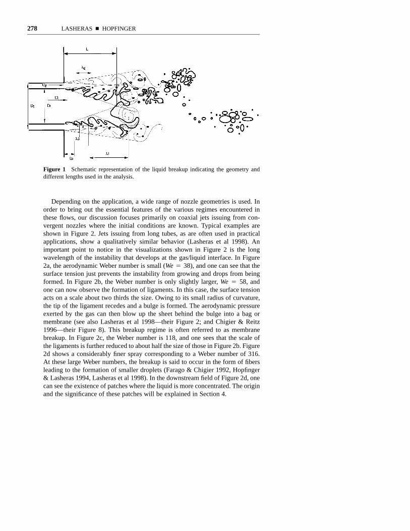
flux ratio, m 4 qlUl Al/qgUg Ag. Here, Al and Ag are the areas of the liquid andgas nozzle cross sections, respectively. In order to fix ideas, the geometry and theexpected instabilities, their wavelengths, and breakup processes are sketched inFigure 1.
1M is actually the dynamic pressure ratio. We keep here the terminology (local) momentumflux ratio used in previous publications.
278 LASHERAS n HOPFINGER
Figure 1 Schematic representation of the liquid breakup indicating the geometry anddifferent lengths used in the analysis.
Depending on the application, a wide range of nozzle geometries is used. Inorder to bring out the essential features of the various regimes encountered inthese flows, our discussion focuses primarily on coaxial jets issuing from con-vergent nozzles where the initial conditions are known. Typical examples areshown in Figure 2. Jets issuing from long tubes, as are often used in practicalapplications, show a qualitatively similar behavior (Lasheras et al 1998). Animportant point to notice in the visualizations shown in Figure 2 is the longwavelength of the instability that develops at the gas/liquid interface. In Figure2a, the aerodynamic Weber number is small (We 4 38), and one can see that thesurface tension just prevents the instability from growing and drops from beingformed. In Figure 2b, the Weber number is only slightly larger, We 4 58, andone can now observe the formation of ligaments. In this case, the surface tensionacts on a scale about two thirds the size. Owing to its small radius of curvature,the tip of the ligament recedes and a bulge is formed. The aerodynamic pressureexerted by the gas can then blow up the sheet behind the bulge into a bag ormembrane (see also Lasheras et al 1998—their Figure 2; and Chigier & Reitz1996—their Figure 8). This breakup regime is often referred to as membranebreakup. In Figure 2c, the Weber number is 118, and one sees that the scale ofthe ligaments is further reduced to about half the size of those in Figure 2b. Figure2d shows a considerably finer spray corresponding to a Weber number of 316.At these large Weber numbers, the breakup is said to occur in the form of fibersleading to the formation of smaller droplets (Farago & Chigier 1992, Hopfinger& Lasheras 1994, Lasheras et al 1998). In the downstream field of Figure 2d, onecan see the existence of patches where the liquid is more concentrated. The originand the significance of these patches will be explained in Section 4.

AIR ASSISTED LIQUID JET ATOMIZATION 279
a b
a b
c d
c d
Figure 2 Images of jet breakup by a coaxial gas flow. The nozzle contraction ratio is7:1, and liquid and gas diameters are Dl 4 7.6 mm, Dg 4 11.3 mm respectively. (a) Ul
4 0.16 m/s and Ug 4 19 m/s, (b) Ul 4 0.55 m/s and Ug 4 21 m/s. (c) Ul 4 0.86 m/sand Ug 4 30 m/s, and (d) Ul 4 0.26 m/s and Ug 4 50 m/s.
Due to the high contraction ratio of the nozzle used in the experiments shownin Figure 2, the velocity profiles at the exit are flat with very thin laminar boundarylayers (vorticity layers) in both the gas and liquid streams. The wavelength of theobserved instability, which as mentioned above, is of the order of the jet diameter,is considerably larger than the thickness of these vorticity layers (by a factor of102). Figure 2d also shows the possible coexistence of a short wavelength insta-bility whose wavelength k2 is shown in Figure 1. For jets issuing from long tubeswith turbulent velocity profiles, the vorticity thickness is also small, and theobserved wavelength is also larger than the diameter of the liquid jet. In contrast,the wavelength of the instability developing in the near-field (up to 10 jet diam-eters) of a high Reynolds number liquid jets discharging into a stagnant gas is

280 LASHERAS n HOPFINGER
Figure 3 Breakup regimes in the parameter space Rel 1 We. Lines of constant M arecalculated for water-air and Dl 4 7 mm. •, conditions of Fig. 2a to 2f; n, conditions ofFigure 6, | | |, regime of rocket engines. ✠ Conditions corresponding to the experimentsanalyzed in section 4. Here, , Rel 4 UlDl/ml; . (Note2 2 2We 4 q U D /r M 4 q U /q Ug g l g g l l
that Dl 4 3.5 mm in Figure 6 and in the measurements of section 4.2. We have shiftedthe values up by a factor of 2 so that these fall in the right range of M.)
always very short compared to the diameter of the liquid jet (Hoyt & Taylor1977a,b).
In order to have an overview of the different breakup and atomization pro-cesses taking place over the wide range of liquid and gas conditions, it is usefulto establish a regime diagram similar to that used for pressure atomizers (Reitz& Bracco 1982, Lin & Reitz 1998). The coaxial jet case of interest here is,however, considerably more complicated. The composition of such a diagram canbe very cumbersome since one has to deal with a much larger number of non-dimensional numbers.
An attempt to establish such a diagram has been made by Farago & Chigier(1992), which excludes the effect of M. A more complete diagram has beenproposed by Hopfinger (1998). Hopfinger’s diagram is reproduced in Figure 3 ina slightly modified form. The various breakup regimes are presented in the param-eter space of the liquid Reynolds number and the aerodynamic Weber number,

AIR ASSISTED LIQUID JET ATOMIZATION 281
and they are calculated for water and the geometry corresponding to the casesshown in Figure 2. Lines of constant M appear as straight lines, Rel 4(We/M)1/2 (Dlr/qlvl
2). Unfortunately, there is not enough experimental data avail-able to give the precise location of the different boundaries to any degree ofaccuracy, except when We r 0 (in this limit the boundaries are shown for Oh ofabout 1013). Recent experiments performed in the range of Weber numbers 20, We , 103 and 800 , Reg , 8.103 (Farago & Chigier 1992, Lasheras et al1998) give a good indication of the upper and lower boundaries of the liquidmembrane breakup. Good atomization, in the sense of a fine spray with uniformlysmall droplets, is achieved beyond the upper boundary of the membrane breakup.The farther to the right or above, the finer is the spray. For a given combinationof M(.1) and We, the mass loading m affects the downstream spray formationby draining kinetic energy from the gas stream. We discuss this effect in moredetail in Section 4.
2.1 Liquid Core Length, L
The momentum flux ratio M is the primary parameter determining the length ofthe unbroken liquid core. When M K 1, this length is determined by the liquidjet (Reitz & Bracco 1982), whereas for M ^ 1 the gas jet is responsible for thebreakup (Hopfinger & Lasheras 1994, Lasheras et al 1998). When M is large, theliquid core is very short, and above a certain critical value Mc (of about 50), agas cavity forms downstream of the liquid core, which is truncated by a recir-culating motion.
The core length L can be estimated from conservation of mass fluxes msAs 4qlUl A1, where Al is the cross sectional area of the liquid nozzle, As is the surfacearea of the liquid core, and ms is the flux of liquid mass shed per unit area (seefor example Przelawas 1996). The problem is to determine this mass flux acrossthe surface As. The semiempirical expression ms 4 C1 /r/ql]
1/32 2[l (q U )l g g
obtained using the capillary wave theory by Mayer (1961) is often used.This gives a core (cone) length
1/3L 1 r4 . (1)1 22/3D 2C M l Ul 1 l l
This formula, which involves an adjustable constant C1, is in reasonably goodagreement with experiments when the physical parameters are not varied over awide range of conditions. However, it does not give the correct limit when thesurface tension goes to zero, as is the case in applications such as liquid propellantrocket engines operating under supercritical conditions. Other empirical correla-tions such as (Arai et al 1985, Eroglu et al 1991, Lin & Reitzb1aL/D 4 C We Rel 2 l
1998) with 0.3 , a , 0.7 and 0.5 , b , 0.5, have the same shortcomings.A different expression for the core length has been proposed by Lasheras et
al (1998). Since the most unstable wavelength measured in the experiments isvery large (of the order of the jet diameter; see Figure 2), they argued that surface

282 LASHERAS n HOPFINGER
tension does not have any effect on the interfacial instability when the Webernumber is large. Using this fact, they were able to generalize the simple entrain-ment model proposed by Rehab et al (1997) to estimate L. This model is basedon dynamic pressure continuity at the interface in the form
2 2q u 4 C q u8 , (2)l e e g g
where is the r.m.s. velocity in the mixing layer (which can be approximatedu8gas 0.17 (Ug 1 Ul)), ue is the velocity at which liquid is entrained, and Ce is aproportionality constant obtained experimentally (Ce ù 0.25) (Rehab et al 1997).Substituting ms 4 qluc in the mass flux conservation, one gets
11L 6 Ulù 1 1 . (3)1) )2D Ul gM!
Liquid propellant rocket engines typically operate at M ' 10 (Herding et al 1998),which results in a liquid core length of about 2Dl (note that for liquid-gas jetsM . 1 also implies Ul/Ug K 1). On the other hand, for high-speed water jetsdischarging into a stagnant or nearly stagnant gas, we have M r 0 (Ug r 0), andEquation 3 reduces to L/Dl ' 6 (ql/qg)1/2. In this limit the core length is indepen-dent of the velocity, and the expression is of the same form as the one given byTaylor (1963). For the case of Ug 4 Ul, the core length is theoretically infinite(see Figure 3, color insert). The actual core length of the water jet depends onthe ratio of the thickness of the vorticity layer at the nozzle exit to the jet diameter.When this ratio is small, the core length of a water jet in air can reach values aslarge as 200Dl (Hoyt & Taylor 1977). For larger ratios, the jet breakup is com-pleted before the initial shear created in the nozzle has relaxed, and the core lengthis considerably shorter. It is known that the core length also depends on the nozzlegeometry (Reitz & Bracco 1982, Hiroyasu et al 1996, Lin & Reitz 1998).
Recent experiments performed in a water-air shear layer (Raynal 1997) indi-cate that Equation 3 is in good agreement with the measured core lengths. Raynalalso measured a weak dependency on Ul, with L decreasing with increasing Ul.One explanation for this weak dependency on Ul is that although surface tensiondoes not affect the instability, it can limit the elongation of the liquid sheet orligaments (3-D effect) by the effect of the surface tension force. In the case shownin Figure 2a, for instance, we can see that this force allows hardly any breakup,whereas in the case of Figure 2b the ligaments reach a considerably longer lengthand subsequently break. To account for this effect, the dynamic pressure balanceat the interface could be modified as:
2 2q u ` Br/d 4 C q u8 , (4)l e e g g
where d is the thickness of the sheet or ligament, and B is a coefficient to befound from experiments. The problem is to formulate an expression for d. Assum-

AIR ASSISTED LIQUID JET ATOMIZATION 283
ing that the minimum thickness is given by the dynamics of the shear layer, onecan use the strain rate-diffusion balance Ug /k } d2/m, and Ul/Ug K 1, to arrive atthe expression
L 6 1' . (5)
1/2D (1 1 B r/l U )l 1 g gM!
The coefficient B1, which depends weakly on the gas Reynolds number andweakly on Oh, is evaluated from Raynal’s (1997) experiments to be about 1013.This expression gives the correct limit when r goes to zero (Raynal 1997). Cor-relations of the type L/Dl } C/Mn with n 4 0.3 have also been proposed byEngelbert et al (1995).
2.2 Spray Angle
The spray angle is also a global quantity of considerable practical interest. Thegrowth rate of the liquid-gas shear layer is related to the liquid jet core length,which for large gas velocities gives an angle tanc ' M1/2/6. This relation remainsvalid as long as the liquid core remains cone-like, that is as long as M is less thanabout 30, giving a maximum angle c of about 408. The spray angle is generallylarger than the liquid-gas shear layer angle because the inertia of the drops allowsthem to escape the shear layer boundary. Raynal (1997) measured spray anglesa of about 508 with respect to the liquid cone surface and this angle was foundto depend only weakly on M. The stability analysis in section 3.1 suggests a sprayangle a of 458 when M1/2 k 1. Because the liquid cone angle increases with M,the total angle h of the spray cone decreases with M from h 4 2(a 1 c/2) '908 to 608.
3. THE NEAR-FIELD REGION
3.1 Linear Stability Analysis of a Liquid/Gas Shear Interface
The classical stability analysis of two parallel flows with different densities hasbeen performed on numerous occasions to study the primary instability devel-oping at a gas/liquid interface (Taylor 1963, Reitz & Bracco 1982, Lin & Lian1989, Lin 1996, and many others). An extension of this analysis to the particularcase of the coaxial jets with high momentum flux ratios of interest here has beendone by Raynal (1997), and Raynal et al (1999). Raynal showed that assumingan infinitely thin shear interface gives results that are not consistent with thefrequencies and wavelengths of the instabilities measured in both two-dimensional gas/liquid shear layers and in axisymmetric coaxial gas/liquid jets.His stability analysis indicates that in order to properly simulate the conditionsencountered in these flows, the vorticity layers resulting from the nozzle’s walls

284 LASHERAS n HOPFINGER
must be included. Furthermore, since the experimental observations suggestedthat the instability has a long wavelength compared to the thickness of the vor-ticity layers (see Figure 2), he assumed that the gas vorticity layer is responsiblefor the instability and that the surface tension can be neglected. In other words,he postulated that the gas stream fixes both the velocity and length scales in theproblem, and that the liquid damps high frequency perturbations and only allowslarge wavelengths to be amplified. Performing a classical linear stability analysisfollowing Chandrasekhar (1961) of a piecewise velocity profile composed of thetwo free streams and a constant vorticity layer in the gas of thickness d2, hecalculated the amplification rate as a function of wave number for values of thedensity ratio S 4 qg /ql ranging from 1 to 1013, and for large values of the velocityratio Ug/Ul. He showed that the preferentially amplified wavelength, as well asits amplification rate, decreases as the density ratio is decreased. When S , 1/10,the amplification rate is proportional to the density ratio qg /ql, while the groupvelocity and the selected wave number are proportional to (qg /ql)
1/2. For the caseof very small density ratios (S 4 1.2 2 1013), he found that the Strouhal numberof the most amplified wave is f dx /Uc 4 7.6 2 1013, where Uc is the groupvelocity.
3.2 Experimental Results
In an attempt to clarify this interfacial instability under the conditions of interesthere (large gas momentum flux and large gas Reynolds number), Raynal (1997)performed a two-dimensional liquid-gas shear layer experiment where he mea-sured both the frequency and the convection velocity of the interfacial wavesunder a wide range of gas and liquid velocities. He measured the frequency ofthe liquid interfacial waves with a laser beam and a photo-diode and determinedthe convection velocity Uc by correlating the photo-diode signal with the signalof a hot-film placed at a known distance downstream of the laser beam.
The measured Strouhal number, based on the vorticity thickness, dx, of thegas layer, f dx /Uc ù 8.7 2 1013, (Figure 4) was in very good agreement withhis linear stability analysis, which, as mentioned above, gives a Strouhal numberof f dx /Uc 4 7.6 2 1013. This value is much lower than the Strouhal numberf dx /Uc 4 0.13 measured in a homogeneous shear layer. The difference is due tothe much larger wavelength developing in the liquid-gas shear layer. This resultsuggests that the liquid damps out the high frequency excitations imposed by thegas stream. The measured convection velocity was found to agree with the oneproposed by Bernal & Roshko (1986) and Dimotakis (1986) for the large eddiesin a shear layer forming between two streams of unequal density U 4c
. Note that if the instability under consideration( q U ` q U )/( q ` q )! ! ! !l l g g l g
here were driven by the liquid vorticity layer, the wavelength would be very shortand consequently the Strouhal number would be large. For large gas velocities,this short wavelength instability k2 can also develop, coexisting with the longwavelength one k1 (see sketch in Figure 1).

AIR ASSISTED LIQUID JET ATOMIZATION 285
Figure 4 Measured frequency of the interfacial instability, f vs Uc/dx. From Raynal et al(1999).
3.3. Primary Drop Formation Mechanisms
3.3.1 Phenomenological Description of the Near-Field Breakup When theinterfacial waves are amplified, the liquid is drawn out into sheets of thickness dby the strain imposed by the gas stream. These sheets subsequently break intodroplets whose sizes are proportional to and of the order of d. The problem thenis to predict the thickness, d, of this sheet. Figure 5 shows a visualization (span-wise view) of the amplification of the interfacial perturbation and breakup of thesheet in the liquid-gas shear layer experiments (Raynal 1997). As the perturba-tions grow and a sheet begins to form, spanwise perturbations at the rim of thesheet also grow (compare, for instance, the left-hand side of Figure 5b with Figure5c and 5d). In time, the sheet’s thickness and rim radius decrease until surfacetension forces become of the order of the aerodynamic forces. The rim is finallydisrupted by aerodynamic forces and Rayleigh instability (see Figure 5e and Fig-ure 5f ). Behind the rim, the liquid sheet is blown out into a bag, forming amembrane, which breaks into small drops. The mechanism shown in Figure 5 ischaracteristic of the relatively small Weber numbers (the Weber number of Figure5 is about 80 based on the liquid layer thickness at the nozzle exit), where mem-brane breakup occurs (see Figure 3). This breakup mechanism is similar to thescenario observed in numerical simulations by Keller et al (1984), Li (1996), andZaleski et al (1998).

286 LASHERAS n HOPFINGER
Figure 5 Visualization of the temporal growth of the interfacial waves leading to sheetand subsequent ligament formation, followed by the breakup into drops. Ul 4 0.42 ms11,Ug 4 22 ms11. From Raynal (1997).
From a simple balance between the aerodynamic forces (drag) acting on therim and the opposing surface tension force, one learns that the drop size, di } d,scales with the Weber number as , where d is the ligament11 12d /D } We } Ui l g
thickness.When the Weber number is large and fiber-type breakup occurs, it is likely
that surface tension is unimportant in determining the final thickness of the sheetor ligament and hence the primary drop size. The size of the fibers df may scalewith the streamwise vortices of the interfacial gas shear layer given by the balancebetween the strain rate ]ug /]x } Ug /k and viscous diffusion rate . Since k }2m /dg f
dx(ql/qg)1/2 the size of the fibers would scale as df /Dl } (mg /UgDl)1/2(dx /Dl)1/2(ql/qg)1/4. With dx } Dl [mg/(Dg 1 Dl)Ug]1/2, for laminar conditions at thenozzle exit, the drop size varies as . The crossover from di } d to13/4d /D } Ui l g
di } df occurs at a certain gas velocity, or Weber number, which corresponds tothe upper boundary of membrane breakup in Figure 3 (We ; 102).
Villermaux (1998) proposed an expression for the initial drop size, valid overthe whole Weber number range, in the form where Wex
11/5 2/5d /d } We (q /q )i x x l g
is defined with . In obtaining this expression it is supposed that the11/2d } Ux g
rate of straining of the liquid sheet is Ui/k, and it continues until surface-tensionforces balance the straining. This expression gives a dependency of di on Ug in

AIR ASSISTED LIQUID JET ATOMIZATION 287
the form . Villermaux further suggested that the vorticity layer grows14/5d } Ui g
with x and replaces dx by the vorticity layer evaluated at the end of the potentialcone. In this case he finds . Other expressions for the initial or primary11d } Ui g
drop size have also been proposed by Przekwas 1996.Measurements made at the edge of the spray, where the drops are thought to
originate from the primary instability, seem to indicate a variation when1nd } Ui g
We ^ 200 and 0.5 , n , 0.7 (Hopfinger 1998). On the other hand, for smallWe, the size of the ligaments seem to decrease inversely proportional to We (seeFigure 2). This would give support to the existence of two regimes. For large Wethe drops resulting from the possible short wavelength instability k2 (see Figure1) are likely to scale on , with 0.5 , n , 2. Further measurements of1nk } U2 g
the drop size in the near-field are required to confirm this conjectures or guidenew models.
4. THE FAR-FIELD OF THE SPRAY
As described above, the primary instability of the gas/liquid interface leads to theformation of liquid sheets and ligaments that break into drops. Due to the large-scale vortical motion of the gas/gas and gas/liquid shear layers shown in Figure1, portions of these sheets and ligaments also may detach from the liquid jet.These liquid droplets and lumps of complex shapes are subsequently convecteddownstream (see sketch in Figure 1) and undergo breakup and coalescence asthey are subjected to the stresses of the surrounding turbulent gas. For the caseof very large aerodynamic Weber numbers, this secondary breakup taking placedownstream of the liquid core may account for a considerable fraction of theliquid atomization, thus determining the final droplet size distribution of the spray(Faeth 1990, Hsiang & Faeth 1992, Lasheras et al 1998).
The secondary breakup is particularly apparent in cases where the length ofthe core is small (as in the condition shown in Figures 6a and 6b), and largeportions of the liquid sheets are pinched off from the liquid by the large eddiesthat develop at the gas/liquid and gas/gas shear layers. This regime, shown inFigure 6, is dominated by the dynamics of the large-scale eddies and manifestsitself as an unsteadiness in the liquid void fraction, thus the name ‘‘superpulsatingmode’’ as used by Farago & Chigier (1992) and Chigier & Reitz (1996).
4.1. Secondary Breakup Mechanisms
Following the classical decomposition of the turbulent motion into a mean plusa fluctuating component, one can express the forces s acting on the liquid particlesas the sum of a force resulting from the mean relative velocity between the dropletand the gas (mean slip velocity), and a force due to the turbulence fluctuationsof the surrounding gas. To differentiate between the breakup processes resulting

288 LASHERAS n HOPFINGER
a
b
Figure 6 Instantaneous flow visualization of the break up of a liquid jet by an annularair jet Ul 4 0.5m/s. a) Ug 4 85m/s, We 4 489, M 4 31; b) Ug 4 56 m/s, We 4 210,M 4 13. From Lasheras et al (1998).
from these two effects, we refer to them as ‘‘shear break up’’ and ‘‘turbulent breakup,’’ respectively.
4.1.1. Shear Break Up When a liquid drop of size d is suddenly exposed to anairflow of constant relative speed, break up occurs if the shear Weber numberexceeds a critical value Weg 4 qg(ug 1 ud)2d/r (Lane 1951). Here ud and ug referto the mean values of the drop and gas velocities. Depending on the value of theshear Weber number, several types of breakup regimes exist: a bag or balloon-type breakup (Merrington & Richardson 1947, Kennedy & Roberts 1990); a strip-

AIR ASSISTED LIQUID JET ATOMIZATION 289
ping or shear breakup (Ranger & Nicholls 1969, Borisov et al 1981); and anexplosive or catastrophic breakup (Hanson et al 1963, Reinecke & Waldman1970). At low relative velocities, the pressure forces from the gas deform thedroplet into a disk shape, which is oriented normal to the relative velocity. At acritical shear Weber number of about 12, the disk deforms into a balloon shape,which is then stretched until it ruptures, producing a bimodal droplet size distri-bution composed of very small droplets resulting from the breakup of the balloonand very large ones from the breakup of the rim. According to Borisov et al(1981), the bag-like breakup regime occurs in the range 12 , Wes , 80 and0.2 , WesRe10.5 , 1.6. At shear Weber numbers greater than 80, one observes asecond breakup mode consisting of the stripping of ligaments that are shed offfrom the surface of the liquid lump, leading to the production of very smalldroplets. This regime appears in the range of 80 , Weg , 2104 and 1 , Weg
Re10.5 , 20 (Borisov et al 1981). For Weber numbers Weg . 2104, a catastrophicor explosive breakup is observed in which the droplet appears to disintegrate veryquickly into a very large number of droplets with sizes much smaller than theparent one. This third mode has been observed exclusively in the interaction ofa droplet with strong shock waves, and thus it is of no interest here. A summaryof these breakup regimes is also given by Faeth (1990). Unfortunately, beyondthe phenomenological descriptions given above, there is virtually no informationon either the breakup time or the droplet size distribution that results from eachone of these regimes. In addition, one has to apply caution in extending the above-mentioned experiments to the situations encountered downstream of the liquidcore in coaxial jets. The drop/shock interaction experiments in which some ofthese modes have been observed involve the sudden acceleration of a droplet andits exposure to a high-temperature dense gas. This causes a Rayleigh/Taylor typeof instability at the accelerating interface and, in some cases, nucleated boilingwithin the droplet, followed by rapid evaporation.
In the situation of interest here, the liquid jet is surrounded coaxially by a high-speed air jet, and the detached sheet and ligaments (such as the ones shown inFigure 6) are not suddenly exposed to a high-speed gas, but rather to a gas speedmuch smaller than the initial gas speed. It is therefore unlikely that an explosivebreakup can occur in the coaxial air–assisted atomization under considerationwhere the initial gas velocity is limited to Mach number unity and the dropletWeber number never reaches values above the initial aerodynamic Weber number,based on the diameter of the liquid jet (,1000). Even in applications such as theatomizers in liquid propellant rocket engines, where the initial aerodynamicWeber number can be very large (low surface tension and large densities), thedrops or liquid patches are not suddenly exposed to these conditions. Recentmeasurements by Lasheras et al (1998) show that although the shear breakup isvery important in the region of several jet diameters downstream of the liquidcore length (in particular the stripping ligament mode; see Figure 6), the resultingdroplets are quickly accelerated up to the gas speed, and their Weber numbersbecome very small at downstream distances greater than or equal to ten jet diam-

290 LASHERAS n HOPFINGER
eters. Beyond this point, the liquid lumps traveling at approximately the samevelocity as the gas are still surrounded by a high intensity turbulent gas, and theturbulent stresses acting on the droplets may lead to their breakup. This breakupprocess continues as the liquid droplets are convected downstream to a locationwhere the turbulent stresses acting on the surface of the droplet become equili-brated with the confinement forces due to viscosity and surface tension. At thispoint, the break up finishes and a frozen PDF is achieved. Thus, it should beexpected that, regardless of the initial break up, the maximum droplet size of theequilibrium (or frozen) PDF achieved in the far-field of coaxial jet sprays shouldbe determined by the final turbulent breakup process.
4.1.2. Turbulent Break up When a liquid lump of size d0 is immersed in aturbulent gas, the turbulent stresses acting on the droplet may be larger than theconfinement stresses due to both surface tension and internal viscous forces, andthe droplet breaks up into smaller ones in a characteristic time tb (Kolmogorov1949, Hinze 1955). When the Reynolds number of the air flow is very large, asin the case considered here (i.e., of the order of 104 to 105), Kolmogorov foundthat if the droplet size compared to the Kolmogorov’s microscale, g, satisfied k
g (ml/mg)3/4, the effect of the viscosity inside the drop is unimportant, and thedetermining factor in the turbulent break up is only the dynamic pressure causedby the velocity change over distance of the order of the droplet diameter. Thedynamic pressure force from the turbulent motion per unit surface is ,2q u(d)g
where is the mean square of the relative velocity fluctuations between two2u(d)points diametrically opposed on the surface of the droplet. The surface tensionforce per unit area is r/d. The turbulent Weber number is then defined as
. Thus, when Wet is greater than a critical value, (Wet)c, of order2We 4 q u(d) d/rt g
1 (Clay 1944), atomization of the liquid occurs because the dynamic pressureforces from the turbulent motion are sufficiently large to overcome the confine-ment of the surface tension (Hinze 1955).
Since the air jet is at a very high Reynolds number, at its centerline an inertialsubrange exists in which the energy spectrum of the turbulence conforms to Kol-mogorov’s hypothesis of local isotropy. In other words, the spectrum of the tur-bulent velocity fluctuations includes a range of high wave numbers (the universalequilibrium range), which is uniquely determined by the turbulent dissipation ratein the air. For this local isotropy to exist, the linear scale of the energy-containingeddies must be large compared to the scale of the small energy-dissipating eddies.For very small values of d(d . g), the form of the universal function can beobtained by dimensional analysis 4 C(ed)2/3. When the residence time of2u(d)the liquid in the turbulent region is longer than the breakup time, the maximumstable droplet size, dmax, can be obtained from the relation d 4max
.3/5 12/5[r(We ) /q ] et c g
In the following we discuss in some detail the statistical description of thedroplet size distribution in the far-field of the spray.

AIR ASSISTED LIQUID JET ATOMIZATION 291
4.2. Statistical Description of the Spray Far-Field
To analyze the process in the far-field, one can use a statistical description of theliquid droplets by introducing a droplet size distribution function (or density func-tion), f (d, x, v, t), defined as the probable number of droplets per unit volumewith diameters in the range about d, located in the spatial range about the vectorposition x, with a velocity in the range about v, at a time t. A Boltzmann-typeequation describing the time evolution of f (d, x, v, t) may be derived, usingarguments similar to those used in the kinetic theory of gases (Williams 1985,Coulaloglou & Tavlarides 1977, Konno et al 1980 1983),
]f ]` ¹ • (vf ) ` ¹ • (Ff ) 4 (Rf ) ` Q8 ` Q8 ` G, (6)x v b c]t ]d
where F(d, x, v, t) is the force per unit mass acting on a liquid particle of size d,and R(d, x, v, t) is the time rate of change of its size due to evaporation orcondensation (which in general depends on the thermodynamic properties of theliquid and on the local temperature and vapor concentration in the surroundinggas). This statistical formulation is widely used in the chemical engineering andcombustion communities to describe the evolution of two-phase flows such asgas/liquid systems or liquid/liquid dispersions (i.e., emulsions) and is referred toas the population balance equation (pbe) or the spray equation. is the timeQ8brate of increase of f due to particle breakup; is the rate of change of f due toQ8cdroplet coalescence; and G is the rate of change of f due to collisions that do notresult in coalescence (i.e., the changes in f resulting from the variation in thevelocity of the particle caused by inter-particle collisions, which did not result incoalescence). Eliminating the velocity dependence by integrating over the wholevelocity space for the steady-state, nonvaporizing flows of interest here, the popu-lation balance equation simply reduces to:
¹ • (vn) ` Q8 dv ` Q8 dv 4 0, (7)x b c# #where n(d, x) 4 * fdv is the mean number density of droplets of size d at alocation x, and v(d, x) 4 (* vfdv)/* fdv is the mean velocity of the liquid dropletof size d at location x. Expanding the first term in Equation 7 yields
v • ¹ n ` n¹ • v 4 Q ` Q , (8)x x b c
with dv, and dv. To close the problem, the use of modelsQ 4 *Q8 Q 4 *Q8b b c c
is required for Qb and Qc. In addition, the mean velocity of the liquid particlesv(d, x) must be calculated from the conservation of mass and linear momentumbetween the phases, which requires information on F.
In what follows we discuss the various theories proposed to calculate Qb andQc and compare them with experiments. The role of the convective term ¹x(vn)in the variation of the droplet size pdf with the downstream distance is not coveredhere. A discussion of this effect can be found in Lasheras et al (1998).

292 LASHERAS n HOPFINGER
The time rate of change of the droplet number density n due to the turbulentbreakup can be calculated as:
`
Q (d, x) 4 m(d )b(d, d )g(d )n(d )d(d ) 1 g(d)n(d), (9)b o o o o o#d
where g(d0) is the break frequency of a droplet of size d0 (or the inverse of thebreakup time tb), m(d0) is the mean number of daughter droplets resulting fromthe breakup of a parent droplet of size d0, and b(d, d0) is the size probabilitydensity function of the daughter droplets formed from the breakage of a motherdroplet of size d0 (Konno et al 1983). The first term on the right-hand side of theequation represents the rate of birth of droplets of size d due to the turbulent breakof larger droplets of size d0, while the second term represents the rate of death(or depletion) of droplets of size d due to their turbulent breakup. Use of Equation9 requires closure models for g(d0), m(d0), and b(d, d0).
4.2.1. Droplet Breakup Frequency, g(do) In the past, a large number of modelshave been proposed for the drop breakup rate, namely the drop elongation in ashear flow (Taylor 1934); turbulent pressure fluctuations (Hinze 1955); relativevelocity fluctuations; and drop/eddy collision, (Coulaloglou & Tavlarides 1977and Prince & Blanch 1990). Despite the above efforts, inconsistencies still existbetween the models and the experiments, and none of them can describe thebreakup frequency over the large range of conditions encountered in the coaxialjet flows of interest here. Using arguments similar to kinetic theory of gases,Prince & Blanch (1990) and Coulaloglou & Tavlarides (1977) have developed aclosure model widely used in the chemical engineering community, whichassumes that the breakup frequency g(d0) is the product of an eddy-drop collisionfrequency and a breakup efficiency, g(d0) 4 * hbekdne, where the collision fre-quency is given by , and the breakup efficiency is calculated2 2 1/2h 4 S (u ` u )be be b e
as . The drawback of this model is that it is based on ank 4 exp(1 E /Ee)r
idealized view of the turbulence composed of an array of eddies of various sizesand energies. In addition, it requires the use of submodels for the droplet/eddycollision cross section hbe, the breakup energy Er, and the number of eddies ofeach size ne. This model predicts a monotonic increase of the breakup frequencywith the droplet diameter, a fact contrary to experimental evidence (Martınez-Bazan (1999 a,b)).
Recently, Martınez-Bazan et al (1999a,b) have proposed a phenomenologicalmodel for g(d0) based on pure kinematic arguments and applicable to the rangeof conditions encountered in coaxial jets. This model gives excellent agreementwith experimental results of the turbulent breakup of bubbles and dropletsimmersed in homogeneous isotropic turbulent flows such as the fully developedregion of turbulent coaxial jets. The model is applicable when the droplets are ofdiameters in the inertial subrange of the turbulence (between the Kolmogorovmicroscale of viscous dissipation and the integral length scale, g , d0 , Lx), and

AIR ASSISTED LIQUID JET ATOMIZATION 293
when the internal viscous deformation forces can be neglected in comparison tothe surface tension forces. Under these conditions, the only two effects acting onthe surface of the droplet are the turbulent stresses and the surface tension. Whenthe average deformation energy per unit volume acting on the surface of thedroplet is greater than the confinement energy2 2/3 2/3e 4 1/2 qu(d ) 4 1/2 qde dt o o
per unit volume due to surface tension , the droplet breaks in a timee 4 6r/ds o
tb. In estimating the deformation energy an homogeneous turbulence flow in equi-librium was assumed and d is an integration constant (see Batchelor 1956). Thiscriterion, first proposed by Kolmogorov, defines a critical diameter dc 4 (12r/dq)3/5e12/5, below which the droplets do not break (Kolmogorov 1949, Baranaevet al 1949, Hinze 1955). Accordingly, the average time tb needed to break a dropletof this size dc is infinite, and the breakup frequency is zero.
Martınez-Bazan et al (1999a) postulated that the surface of any other dropletwith a diameter greater than dc will deform with an acceleration ab which, on theaverage, is proportional to the difference between the deformation and the con-finement forces acting on it:
2d u(d) 6ra 4 4 1 . (10)b 2 2t 2d qdb
This simple argument suggests that the break frequency depends not only on thedroplet size but also on e as
r2u(d) 6r 2/38.2(ed) 1 121 ! qdl 2d qdg(e, d) 4 4 4 K , (11)! gt d db
where Kg is the only proportionality constant involved in the model (Figure 7).The model shows that in the limit of very large droplets, d/dc k 1, surface
tension effects are very small and the breakup frequency decreases with the drop-let size as g(e, d) ' e
1⁄3 d12⁄3, while for small droplets, dc , d , dgmax, it increases
rapidly with the drop diameter as g(e, d) ' e13/5 (r/q)12/3 . It alsod/d 1 1! c
predicts a diameter dgmax 4 1.63dc for which the breakup frequency is maximum.Experiments conducted by Martınez-Bazan et al (1999 a,b), and Eastwood et
al (1999) (Figure 8) show that in the range d/dc k 1, the breakup frequency iswell predicted by the model and increases as e
1⁄3. However, no experimental con-firmation exists of the value of dgmax.
4.2.2. Number and Size PDF of the Daughter Droplets Resulting from theTurbulent Break Up Three main approaches have been used to model b(d,d0):phenomenological models based on surface energy considerations (Tsouris &Tavlarides 1994); statistical models (Coulaloglou & Tavlarides 1977, Prince &Blanch 1990, Longuet-Higgins 1992, Novikov & Dommermuth 1997); andhybrid models based on a combination of both (Konno et al 1983, Cohen 1991).

294 LASHERAS n HOPFINGER
Figure 7 Breakup frequency g(e, d) and breakup velocity model proposed by Martınez-Bazan et al (1999a).
Figure 8 Comparison of the breakup frequency measured experimentally with the modelgiven by Equation 11. From Martınez-Bazan et al (1999a).

AIR ASSISTED LIQUID JET ATOMIZATION 295
Among the most widely used phenomenological models based on surface energyconsiderations is the one proposed by Tsouris & Tavlarides (1994). They assumedthat, upon breakup, only two daughter droplets of size d1 and d2 are formed whosemost probable sizes are inversely proportional to the amount of surface energycreated in the breakup process. This gives a minimum probability for the for-mation of two particles of the same size (since their surface energy is maximum),and a maximum probability for the formation of a pair made up of a very largeparticle and its complementary very small one
e ` [e 1 e(d )]min max 1b(d , d ) 4 , (12)1 0 d0
(e ` [e 1 e(d )])ddmin max 1 1#0
where the energy to form a particle of size d1 is given by: 2e(d ) 4 prd `1 1
. The maximum energy emax corresponds to the formation of two2prd 2 1 prd2 0
particles of equal volume d1 4 d2 4 . This PDF has a U-shape with a1/3d /20
minimum value when a particle of minimum diameter and a complementary oneof maximum size are formed. This model has been shown to lead to results thatare not consistent with the experimental distributions measured in stirred tanksand other turbulent flows (Hesketh et al 1991, Sathyagal & Ramkrishna 1996,Kostoglou & Karabelas 1998, Martınez-Bazan et al 1999a,b, and others). In addi-tion, an important yet unresolved issue in the model is the need to define a cri-terion for the value of dmin.
Statistical distributions have also been proposed by Coulaloglou & Tavlarides(1977), Prince & Blanch (1990), and others. Coulaloglou & Tavlarides alsoassumed a binary breakup and that the probability distribution function b(d, d0)is given by a normal distribution (as proposed by Valentas & Amundson 1966).Purely statistical models have also been proposed by Longuet-Higgins (1992),Novikov & Dommermuth (1997), and others. Longuet-Higgins proposed a simplemechanism for the breakup process consisting of a series of random divisions ofa cubical block by a number of planes parallel to the faces of the block. In studyingthe PDF resulting from the cuts performed in one, two, and three dimensions, heobtained an infinite number of possible distributions, depending on the numberof random partitions performed in the initial dimension. Adjusting the combina-tion of the number of cuts performed in each dimensions, he showed that themodel could fit various experimental results (Longuet-Higgins 1999). Novikov& Dommermuth (1997) extended Kolmogorov’s similarity arguments and pro-posed a statistical description of the droplets in turbulent sprays using ideas ofsimilarity, cascade process, and infinitely divisible distributions. These statisticalmodels can describe the droplet size PDF measured in the far-field of the coaxialjets.
Konno et al (1980, 1983) proposed a hybrid model based on the assumptionthat three daughter droplets are produced from the breakup of one mother, m 43, and the probability of obtaining a certain combination of droplets is weighted

296 LASHERAS n HOPFINGER
by a factor proportional to the energy contained in the turbulent scales of sizesequal to the size of the daughter droplets
P } E(K )E(K )E(K ). . . . E(K ), (13)1 2 3 m
where E(Ei) is the spectrum function of the turbulent kinetic energy. Konno’sdistribution gives a low probability for combinations of very large and very smallparticles and gives a maximum probability for combinations of particles of similarsizes, a result totally opposite to Coulaloglou & Tavlarides’ model. Konno’smodel is also deficient in that the distribution of the daughter droplets is dependenton neither the size of the mother droplets, nor the turbulent kinetic energy of theunderlying turbulence, two facts contrary to experimental observations. In fact,Konno’s distribution is practically a universal one and can be approximated by abeta function (Konno et al 1983).
A hybrid model based on energy and entropy considerations has been proposedby Cohen (1991). Using entropy arguments, he found that the most probabledistribution resulting from the shattering of a mother droplet is similar to the betafunction proposed by Konno (1983). However, his PDF model incorporated adependency with e. Although Cohen’s model is an elegant one, it has the draw-back of producing an explosive breakup in which a very large number of daughterdroplets (several thousands) are formed, a fact not yet observed in anyexperiments.
Martınez-Bazan et al (1999b) have recently proposed a model for b(d, d0) thatassumes a cascade of binary droplet divisions (m 4 2) and is based on an exten-sion of the kinematic arguments used in their breakup frequency model (Figure9).
When a droplet of size d0 breaks into two droplets of sizes d1 and d2, thedaughter size PDF, b(d,d0), is assumed to be proportional to the product of thedifference in the stresses associated with the formation of a droplet of size d1,Ds1 4 1/2 qc(ed1)2/3 1 6r/d0, and the formation of the complementary dropletof size d2, Ds2 4 1/2 qc(ed1)2/3 1 6r/d0
1 6r 1 6r2/3 2/3b(d, d ) 4 K qc(ed ) 1 qc(ed ) 1 . (14)0 b 1 23 4 3 42 d 2 do o
This model predicts a dependency of the PDF on both d0 and e is in very goodagreement with experiments performed on the breakup of liquid droplets or bub-bles injected into the fully developed region of high Reynolds number turbulentjets.
Figure 10 shows a comparison of the various droplet size distribution modelsdiscussed above. At very high values of the dissipation rate, Martınez-Bazan’smodel closely resembles Konno’s model, while it differs considerably for smalle. On the other hand, Tavlarides’ model is diametrically opposed to the other twomodels.

AIR ASSISTED LIQUID JET ATOMIZATION 297
Figure 9 Dependency of the daughter size PDF, b(d, d0) on (a) the dissipation rate ofturbulent kinetic energy and (b) the droplet size. From Martınez-Bazan et al (1999b).

298 LASHERAS n HOPFINGER
Figure 10 Comparison of the various models proposed for the size PDF of the daughterdroplets formed from the turbulent breakup of a mother one of size d0.
4.2.3 Models for the Droplet Coalescence The turbulence of the surroundinggas results in drop/drop collisions and thereby in the possibility of coalescence.However, only a fraction of those collisions involving a sufficient amount ofkinetic energy result in a coalescence (Brazier-Smith et al 1972, Ashgriz & Poo1990, Jiang et al 1992, and others). When two droplets collide, a thin film of airforms between the two colliding droplets and acts as a cushion, which may causethem to rebound. If the time involved in a collision is sufficiently large, the airfilm separating the droplets gradually thins down below a certain threshold, theboundary between the two droplets will adhere and coalesce. Inversely, if theturbulence of the surrounding gas is sufficiently high (large e), the time involvedin the drop/drop collision is shorter than that needed for the film’s drainage, andthe droplets will rebound without undergoing coalescence.
The rate of change of the droplet number density n due to coalescence can becalculated as

AIR ASSISTED LIQUID JET ATOMIZATION 299
m/2
Q 4 h(m 1 m8, m8)k(m 1 m8, m8)n(m 1 m8, m8)n(m8)d(m8)C #0
`
1 n(m8) h(v, m8)k(v, m8)n(m8)d(m8), (15a)#0
where h(v, m8) is the collision frequency of drops of volumes v and v8, whichdepends on the dissipation rate of turbulent kinetic energy (relative velocitybetween two droplets) and the droplet number density. k(v, v8) is the coalescenceefficiency of collision between drops of volumes v and v8. The coalescence effi-ciency depends on the ratio between the droplet’s contact time and a criticaldrainage time, T. The drainage time is
lr 12/3 12/3T ' e dq1
(Tsouris & Tavlarides 1994, Jeffreys & Davis 1971). The contact time can beestimated as the reciprocal of the fluid velocity fluctuations between two pointsseparated by a distance equal to the droplet’s diameter, or turnover time t 'e11⁄3 d 2⁄3. The coalescence efficiency is given by
Tk ' exp 1 . (15b)1 2
t
The maximum drop diameter for which separation is possible (coagulation will
be prevented) is given by the cut-off condition 4 T, which givest
l8 11/4d } e . (16)max q1
4.2 Experimental Results of the Far-Field Droplet SizeDistributions in Coaxial Jets
Lasheras et al (1998) have shown that the nonmonotonic variation of the dropletsize measured along the central axis of the spray in the far-field x/D1 . 10 (Figure11) can be explained by the competition between turbulent breakup and coales-cence effects. Assuming local isotropy and fully developed turbulence at thecentral axis of the jet, the argument made is that both turbulent breakup andcoalescence depend only on the value of the dissipation rate of turbulent kineticenergy e.
The maximum droplet size that can withstand turbulent breakup is d 4c
, while the maximum droplet size above which coalescence is3/5 12/3(12r/dq) enegligible is . Thus, in regions of high e (after the length of11/4d ' l /q emax g 1
the liquid cone) turbulent breakup dominates, while further downstream, as equickly decays, turbulent breakup ends, and coalescence effects determine thedrop size (Shinnar 1961). Lasheras et al (1998) showed that the critical distance

300 LASHERAS n HOPFINGER
Figure 11 Downstream variation of the Sauter mean diameter(d32) measured at the jet’scenterline, Ug 4 140m/s and Ul 4 0.13, 0.20, 0.31, 0.43, and 0.55 m/s. From Lasheraset al (1998).
downstream from the nozzle needed for the turbulent breakup to be completedcan be estimated by equating the liquid residence time tr 4 *x ]n/U(n) 4
to the droplet breakup time obtained from Equation 11 as2x /2Ucrit g
dt 4 . (17)b
r2/3K 8.2(ed) 1 12g! qd
The remaining problem is obtaining an expression for e that takes into accountthe presence of the liquid mass loading. From energy conservation considerations,Lasheras et al (1998) proposed:
3Uge } . (18)D (1 ` m)g
This estimate of the dissipation rate gives a value for the distance downstreamup to which turbulent breakup takes place

AIR ASSISTED LIQUID JET ATOMIZATION 301
13/5 2/51 r14/5x } U , (19)crit g 3 4 1 2D (1 ` m) qg g
and the value of dc at the end of the breakup region as:
12/5 3/53U rgd } . (20)c 3 4 1 2D (1 ` m) qg g
Recent measurements of d90% and d32 performed over a wide range of gas veloc-ities and liquid mass loadings were found to compare well with the dmax and xcrit
given by the above equations (Lasheras et al 1998). Assuming similarity distri-butions so that the maximum critical diameter is proportional to the Sauter meandiameter (SMD), dc } d32, the above equation also shows that , with1bd ; U32 g
the exponent b varying between 6/5 to 8/5 depending on liquid mass loading.Most of the drop size measurements reported in the literature on coaxial jet spraysare made downstream of the liquid intact length at x/Dl . 10, and they are empir-ically correlated with a power law of the form , with the exponent b1bd ; U32 g
typically ranging from about 0.8 to 1.4 (Ingebo 1992) and occasionally even 2(Nukiyama & Takasawas 1989, Gomi 1985). The good agreement between theexperimental measurements and the prediction of Equations 19 and 20 givesstrong support to the model. It is important to remark that the secondary atomi-zation described above does not play a role in all regimes shown in Figure 3; itonly becomes relevant in the cases where the dissipation rate of turbulent kineticenergy e given by Equation 18 is very large. The droplet size distribution mea-surements of Lasheras et al were performed only for very large gas speeds andvery small liquid loadings (M . 100), corresponding to very large values of e.
Downstream of xcrit the turbulent kinetic energy of the air can no longer providesufficient pressure deformation forces to overcome the confinement due to thesurface tension. From this location onward, droplet coalescence, droplet decel-eration, and evaporation determine the drop size distribution. The maximum dropdiameter in this region is given by Equation 16 with the local dissipation rategiven by (x/Dg)14. This gives a nearly linear dependency of dmax on thee 4 qdownstream distance x, which is in agreement with the measurements shown inFigure 10. The turbulent model of Borghi (Vallet & Borghi 1998) also predictsuch a nearly linear increase in this region.
5. THE EFFECT OF THE ADDITION OF SWIRL TO THEGAS STREAM
It is well known that the addition of swirl can not only enhance the jet breakup,but also increase the lateral spreading of the liquid droplets. In the liquid-gascoaxial jet configurations, attempts to enhance jet breakup have generally beenmade by swirling the liquid jet. At first sight this seems a logical approach con-sidering the large density of the liquid compared with the gas. The importance of

302 LASHERAS n HOPFINGER
the momentum flux ratio in liquid jet breakup discussed in Section 2 suggests,however, that when M . 1 the addition of swirl to the gas stream is the optimalmethod to produce an enhancement of the liquid breakup. Hopfinger & Lasheras(1996) and Hardalupas & Whitelaw (1998) showed that a swirl in the gas jet isindeed very effective in breaking up the liquid jet when a critical swirl numberis exceeded. The swirl number is usually defined by the ratio of axial flux ofangular momentum to axial linear momentum flux, which in this case is closelyapproximated by S 4 Ut /Ug, where Ut is the tangential gas velocity at the nozzleexit and Ug is the axial velocity as above. The effect of a gas swirl is clearlyapparent by comparing the flow visualizations shown in Figures 12a and 12b.These conditions fall within the membrane breakup regime shown in Figure 3.Thus, large membrane surfaces are clearly visible in Figure 12b. The value of S4 1.27 is somewhat above the critical value Scr required for the onset of theformation of a central recirculating flow (similar to vortex breakdown). For theconditions of M 4 2.2, Scr ' 1 considered, a central recirculating flow is estab-lished, and a stagnation point on the central axis of the jet appears. In the exper-iments conducted with the geometry indicated above, Hopfinger & Lasheras(1996) found that the Scr decreases when M increases and reaches an asymptoticvalue of about 0.4 at large M.
When the depression on the jet’s centerline caused by the azimuthal motionof the gas becomes equal to the dynamic pressure of the fluid mixture existingon the axis, a flow reversal occurs, and a phenomenon similar to a vortex break-down takes place. Using this criterion, Hopfinger & Lasheras obtained an expres-sion for the critical swirl number in the form
1/2 1/2a (1 1 a) M2S 4 1 ` r , (21)cr 11 2 3 42 2r 2M ln(D /D ) a r1 2 1 g
where rg and g denote respectively the ratios of axial air and liquid velocities atthe jet’s nozzles and at the center line at the stagnation point location, rg 4Ug/ug(z), rl 4 Ul/ul(z), and a is the local value of the volumetric void fraction ofthe liquid.
There are two limiting regimes given by either very small or very large valuesof the momentum flux ratio M. For M of order 1, we have m 4
. Under these conditions, and consistent with the experimentalq A U /q A U k 1l l l g 2 g
observations, one can assume that the flow reversal occurs at a downstream loca-tion where, without swirl, the liquid core would remain unbroken (a 4 1 at thecenter), and the liquid velocity is close to Ul (rl 4 1). The critical swirl number(Equation 21) is then given by
11/2S 4 [2M ln(D /D )] . (22)cr g l
In the other limiting case of M k 1 (corresponding also to small liquid to airmass flow rates m K 1), the experimental observations show that prior to theflow reversal, the liquid core is quickly atomized by the high-speed coaxial gas

AIR ASSISTED LIQUID JET ATOMIZATION 303
Figure 12 Images of water jet breakup with and without swirl of the coaxial gas jet forUl 4 0.55 m s11 and Ug 4 22 m s11, M 4 2.2. (a), S 4 Ul/Ug 4 0; (b), S 4 1.27. Dl
4 7.6 mm, Dg 4 11.3 mm.
jet. Thus, in this case one can assume a 4 m K 1, and the leading term inEquation 21 is now
2 11/2S 4 [2r ln(D /D )] , (23)cr g g l
indicating that Scr is independent of M. Estimating rg 4 2.5, the above equationgives Scr ' 0.4 for the conditions studied by Hopfinger & Lasheras.
304 LASHERAS n HOPFINGER
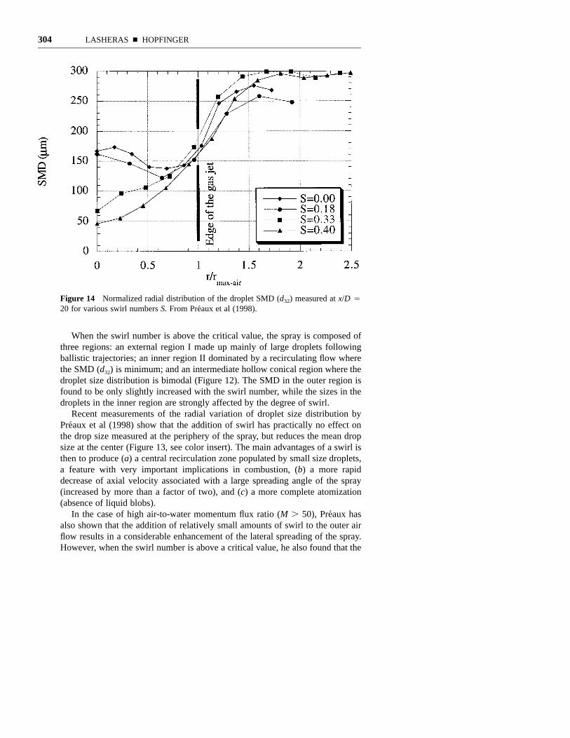
Figure 14 Normalized radial distribution of the droplet SMD (d32) measured at x/D 420 for various swirl numbers S. From Preaux et al (1998).
When the swirl number is above the critical value, the spray is composed ofthree regions: an external region I made up mainly of large droplets followingballistic trajectories; an inner region II dominated by a recirculating flow wherethe SMD (d32) is minimum; and an intermediate hollow conical region where thedroplet size distribution is bimodal (Figure 12). The SMD in the outer region isfound to be only slightly increased with the swirl number, while the sizes in thedroplets in the inner region are strongly affected by the degree of swirl.
Recent measurements of the radial variation of droplet size distribution byPreaux et al (1998) show that the addition of swirl has practically no effect onthe drop size measured at the periphery of the spray, but reduces the mean dropsize at the center (Figure 13, see color insert). The main advantages of a swirl isthen to produce (a) a central recirculation zone populated by small size droplets,a feature with very important implications in combustion, (b) a more rapiddecrease of axial velocity associated with a large spreading angle of the spray(increased by more than a factor of two), and (c) a more complete atomization(absence of liquid blobs).
In the case of high air-to-water momentum flux ratio (M . 50), Preaux hasalso shown that the addition of relatively small amounts of swirl to the outer airflow results in a considerable enhancement of the lateral spreading of the spray.However, when the swirl number is above a critical value, he also found that the

AIR ASSISTED LIQUID JET ATOMIZATION 305
droplet size distribution and the liquid void fraction exhibit stronger radial inhom-ogeneities throughout the spray (Figure 14). The degree of non-uniformitydepends on the swirl number.
The above results indicate that the primary atomization is the mechanism mostlikely to be responsible for the atomization of the droplets in the outer region,while turbulent breakup appears to play a major role in the intermediate region.Although this intermediate region is pushed outward with increasing swirl, themean size of the droplets existing there was found to be independent of the swirlnumber, a result consistent with the model shown in Section 4.
ACKNOWLEDGMENTS
Many ideas and results presented in this paper must be shared with our colleaguesE. Villermaux, L. Raynal, C. Martınez-Bazan, and J. Montanes. The work wasfinancially supported by the SEP (Societe Europeenne de Propulsion) under con-tract n8 910023 (EJH), and by the US Office of Naval Research under contractONR#N00014-96-1-0213 (JCL).
Visit the Annual Reviews home page at www.AnnualReviews.org.
LITERATURE CITED
Arai M, Shimizu M, Hiroyasu H. 1985.Breakup length and spray angle of highspeed jets. Proc. 3rd Int. Conf. Spray Sys-tems, pp. IB/4/1-IB/4/10
Ashgriz N, Poo JY. 1990. Coalescence and sep-aration in binary collisions of liquid drops.J. Fluid Mech. Vol. 221, pp. 183–204.
Baranaev Y, Tevenovskiy N, Treguboval EL.1949. On the measurements of minimalfluctuations in turbulent flows. Dokl. Akad.Novk. SSSR, 66(5) 821–2424
Batchelor GK. 1956. The Theory of Homoge-neous Turbulence. Cambridge, UK: Cam-bridge Univ. Press
Bernal LP, Roshko A. 1986. Streamwise vortexstructure in a plane mixing layer. J. FluidMech. 170:499–525
Borisov A, Gelfand B, Natanzon M, KossovO. 1981. Droplet break regimes and criteriafor their existence. J. Engin. Phys. 40(1)
Brazier-Smith PR, Jennings SG, Latham J.1972. The interaction of falling drops: coa-lescence. Proc. R. Soc. London, A 326:393–408
Chandrasekhar S. 1961. Hydrodynamic andHydromagnetic Stability. New York: Dover.
Chigier N, Reitz RD. 1996. Regimes of jetbreak up and break up mechanisms. Recentadvances in spray combustion: spray atom-ization and droplet burning phenomena.Progress in Astronautics and Aeronautics.Volume 166. pp 109–136
Clay PH. 1940. Proc. R. Acad. Sci. Amster-dam, The Netherlands 43:852
Cohen RD. 1991. Shattering of a liquid dropdue to impact. Proc. R. Soc. London, A435:483–503
Coulaloglou CA, Tavlarides LL. 1977.Description of interaction processes in agi-tated liquid-liquid dispersions. Chem.Engin. Sci. 32:1289–97
Dimotakis PE. 1986, Two-dimensional shearlayer entrainement. Am. Inst. Aeronaut.Astronaut. J. 24(11):1791–96
Eastwood E, Lasheras JC. 1999. Effect of thedensity and viscosity ratio on the breakupfrequency of a droplet injected into a tur-bulent flow. Phys. Fluids. To be submitted

306 LASHERAS n HOPFINGER
Engelbert C, Hardalupas Y, Whitelaw JH.1995. Breakup phenomena in coaxial air-blast atomizers. Proc. R. Soc. London A451:189–229
Eroglu H, Chigier N, Farago Z. 1991. Coaxialatomizer liquid intact lengths. Phys. FluidsA3(2):303–8
Faeth GM. 1990. Structure and atomizationproperties of dense sprays. Int. Symp. Com-bustion. pp. 1345–52. Pittsburgh, PA: Com-bustion Institute
Farago Z, Chigier N. 1992. Morphologicalclassification of disintegration of round jetsin a coaxial airstream. Atomization Sprays,2:137–53
Gomi H. 1985. Pneumatic atomization withcoaxial injectors. NAL-TR-888T, N 86-27595
Hanson AR, Domich EG, Adam HS. 1963.Shock tube investigation of the break-up ofdrops by air blast. Phys. Fluids 6:1070–80
Hardalupas Y, Whitelaw JH. 1998. Coaxial air-blast atomizers with swirling air stream.Recent advances in spray combustion: mea-surements and model simulation Vol. II.Progress in Astronaut. Aeronaut. Am. Inst.Aeronaut. Astronaut. 171:201–32
Herding G, Snyder R, Rolon C, Candel S.1998. Investigation of cryogenic propellantflames using computerized tomography ofemission images. J. Propulsion Power13(2):146–51
Hesketh RP, Etcgells AW, Russell TWF. 1991.Bubble break up in a pipe flow. Chem.Engin. Sci. 46:(1):1–9
Hinze JO. 1955. Fundamentals of the hydro-dynamic mechanism of splitting in disper-sion processes. Am. Inst. Chem. Engin. J.289–95
Hiroyasu H, Arai M, Shimizu M. 1996.Breakup length of a liquid jet and internalflow in a nozzle. Recent advances in spraycombustion: spray atomization and dropletburning phenomena. Progress in Astronaut.Aeronaut. Am. Inst. Aeronaut. Astronaut.166:173–84
Hopfinger EJ. 1998. Liquid jet instability andatomization in a coaxial gas stream. Proc.
Eur. Turbulence Conf. 7, ed. U. Frisch,Advances in Turbulence VII. Kluwer Aca-demic. In press
Hopfinger E, Lasheras JC. 1994. Break-up ofa water jet in a high velocity co-flowing air.Proc. Sixth Int. Conf. Liquid Atomizationand Spray Systems, ed. Yule & Dumouche,pp. 110–117. New York: Begell House
Hopfinger EJ, Lasheras JC. 1996. Explosivebreakup of a liquid jet by a swirling coaxialgas jet. Phys. Fluids. 8:1696–98
Hoyt JW, Taylor JJ. 1977a. Waves on waterjets. J. Fluid Mech. 83:
Hoyt JW, Taylor JJ. 1977b. Turbulence struc-ture in a water jet discharging in air. Phys.Fluids 20(10):1–20
Hsiang L-P, Faeth GM. 1992. Near-limit defor-mation and secondary break up. Int. J. Mul-tiphase Flows. 18(5):635–52
Ingebo RD. 1992. Effect of gas mass flux oncryogenic liquid break-up. Cryogenics32(2):191–93
Jeffreys GV, Davies GA. 1971. Coalescence ofliquid droplets and liquid dispersion.Recent Advances in Liquid-Liquid Extrac-tion, ed. C. Hanson, p. 495. New York:Pergamon
Jiang YJ, Umemura A, Law CK. 1992. Anexperimental investigation on the collisionbehavior of hydrocarbon droplets. J. FluidMech. 234:171–90
Keller FX, Li J, Vallet A, Vandromme D,Zaleski S. 1984. Direct numerical simula-tion of interface breakup and atomization.Proc. Sixth Int. Conf. Liquid Atomizationand Spray Systems, ed. Yule & Dumouchel.New York: Begell House
Kennedy JB, Roberts J. 1990. Rain ingestionin gas turbine engines. Proc. 4th Annu.Conf. Instabilities of Liquid AtomizationSpray Systems, pp 154–162. Hartford, CT.
Kolmogorov AN. 1949. On the disintegrationof drops by turbulent flows, Dokl. Akad.Nank. SSSR, 66:825–28
Konno M, Aoki M, Saito S. 1983. Scale effecton breakup process in liquid-liquid agitatedtanks. J. Chem. Engin. Japan 16(4):313–19

AIR ASSISTED LIQUID JET ATOMIZATION 307
Konno M, Matsunaga Y, Arai K, Saito S. 1980.Simulation model for break-up process inan agitated tank. J. Chem. Engin. Japan13(1):67–73
Kostoglou M, Karabelas AJ. 1998. On theattainment of steady state in turbulent pipeflows of dilute suspensions. Chem. Engin.Sci. 53(3):505–13
Lane WR. 1951. Shatter of drops in stream ofair. Ind. Eng. Chem. 43(6):1312–17
Lasheras JC, Villermaux E, Hopfinger EJ.1998. Break-up and atomization of a roundwater jet by a high speed annular air jet. J.Fluid Mech. 357:351–79
Lefebvre AH. 1989. Atomization and Sprays.New York: Hemisphere
Li J. 1996. Resolution numerique de l’equationde Navier-Stokes avec reconnectiond’interfaces: Methode de suivi de volume etapplication a l’atomization. These de Doc-torat, Univeriste Pierre et Marie Curie, Paris
Liang PY, Ungerwitter RJ. 1996. Modeling andatomization of secondary breakup from firstprinciples. Recent advances in spray com-bustion: spray atomization and dropletburning phenomena. Vol. I. Prog. Astro-naut. Aeronaut. 166:481–504
Lin SP. 1996. Regimes of jet break up andbreak up mechanisms (Mathematicalaspects). Recent advances in spray com-bustion: spray atomization and dropletburning phenomena. Vol. I, Prog. Astro-naut. Aeronaut. 166:109–136. Am. Inst.Aeronaut. Astronaut.
Lin SP, Lian ZW. 1989. Absolute instability ofa liquid jet in a gas. Phys. Fluids 32:120–26
Lin SP, Reitz RD. 1998. Drop and spray for-mation from a liquid jet. Annu. Rev. FluidMech. 30:85–105
Longuet-Higgins M. 1992. The crushing of aircavities in a liquid. Proc. R. Soc. London.A. 439:611–26
Martınez-Bazan C, Montanes JL, Lasheras JC.1999a. On the break up frequency of an airbubble injected into a fully developed tur-bulent flow. J. Fluid Mech. 401:157–182
Martınez-Bazan C, Montanes JL, Lasheras JC.1999b. On the size pdf resulting from thebreak up of an air bubble immersed into aturbulent liquid flow. J. Fluid Mech.401:183–207
Mayer E. 1961. Theory of liquid atomizationin high velocity gas streams. ARS31(12):1783–85
Merrington A, Richardson EG. 1947. Thebreak up of liquid jets. Proc. Phys. Soc.59:1
Novikov EA, Dommermuth DG. 1997. Distri-bution of droplets in a turbulent spray.Phys. Rev. E. 56(5):5479–82
Nukiyama GE, Takasawa Y. 1989. Experi-ments on the atomization of liquids bymeans of air streams, parts III and IV.Transact. Soc. Mech. Eng. Japan 5(18):63–75
Plateau J. 1873. Stattique Experimentale etTheoretique des Liquids Soumie Aux SeulesForces Moleicularies. Paris: ChanthierVallars
Przekwas AJ. 1996. Theoretical modeling ofliquid jet and sheet breakup processes. InRecent Advances in Spray Combustion:Spray Atomization and Droplet BurningPhenomena. Prog. Astronaut. Aeronaut.166:211–39.
Preaux G, Lasheras JC, Hopfinger EJ. 1998.Atomization of a liquid jet by a highmomentum coaxial swirling gas jet. Proc.3rd Int. Conf. Multiphase Flow, Lyon.France.
Prince WJ, Blanch HW. 1990. Bubble coales-cence and breakup in air-sparged bubblecolumns. Am. Inst. Chem. Eng. J.36(10):1489–99
Ranger R. and Nicholls JA. 1969. The aero-dynamics of shattering of liquid drops. Am.Inst. Aeronaut. Astronaut. J. 7:285–90
Rayleigh L. 1879. On the instability of jets.London Math. Soc. 10:361–71
Raynal L. 1997. Instabilite et entrainement al’interface d’une couche de melangeliquide-gaz. These de Doctorat, UniversiteJoseph Fourier, Grenoble.

308 LASHERAS n HOPFINGER
Raynal L, Villermaux E, Hopfinger EJ. 1999.Primary instability of a plane liquid-gasshear layer. J. Fluid Mech. Submitted
Rehab H, Villermaux E, Hopfinger EJ. 1997.Flow regimes of large velocity ratio coaxialjets. J. Fluid Mech. 345:357–81
Reinecke WG, Waldman GD. 1970. A study ofdrop break up behind strong shocks andapplications to flight. AVCO Report A VSD-0110-70-77
Reitz RD, Bracco FV. 1982. Mechanism ofatomization of a liquid jet. Phys. Fluids,25:1730–42
Sathyagal AN, Ramkrishna D. 1996. Dropletbreakup in stirred dispersions. Breakagefunctions from experimental drop-size dis-tributions. chemical engineering sciences.51(9):1377–91
Scardovelli R, Zaleski S. 1999. Direct numer-ical simulation of free surface and interfa-cial flows. Annu. Rev. Fluid Mech. 33:567–603
Shinnar R. 1961. On the behavior of liquid dis-persions in mixing vessels. J. Fluid Mech.10:259–75
Taylor GI. 1934. The formation of emulsionsin definable field of flow. Proc. R. Soc. Lon-don, Ser. A 146:501
Taylor GI. 1963. Generation of ripples by windblowing over a viscous liquid. In The Sci-
entific Papers of Sir G. I. Taylor, ed. G. K.Batchelor, 3:244–54 Cambridge, UK: Cam-bridge Univ. Press
Tsouris C, Tavlarides LL. 1994. Breakage andcoalescence models for drops in turbulentdispersions. Am. Inst. Chem. Eng. J.40(3):395–406
Valentas KJ, Amudson NR. 1966. Breakageand coalescence in dispersed phase sys-tems. Eng. Chem. Fundam. 5:533–42
Vallet A, Borghi R. 1998. An Eulerian modelof the atomization of a liquid jet. Proc. 3rdInt. Conf. on Multiphase Flows. ICMF’98.Lyon, France, June 8–12
Villermaux E. 1998. Mixing and spray forma-tion in coaxial jets. J. Prop. Power 14(5):
Weber C. 1931. Zum zerfall eines flussigkeits-trahles (on the disruption of liquid jets). Z.Angew. Math. Mech. 2(2)
Wierzba A, Takayama K. 1987. Experimentalinvestigations of liquid droplet breakup ina gas stream. Rep. Inst. High Speed Mech.53(382):2–93
Williams FA. 1985. Combustion Theory.Menlo Park, CA: Benjamin/Cummings.2nd ed.
Zaleski S, Li J, Succi S. 1998. Two-dimen-sional Navier-Stokes simulation of defor-mation and breakup of liquid patches. Phys.Rev. Lett. 75:244–47

LASHERAS ■ HOPFINGER C-1
Fig
ure
13Li
quid
voi
d fr
actio
n an
d dr
ople
t si
ze d
istr
ibut
ions
in a
coa
xial
spr
ay w
ith a
sw
irl n
umbe
r ab
ove
the
criti
cal.
Fro
m P
reau
x et
al 1
998.

Copyright of Annual Review of Fluid Mechanics is the property of Annual Reviews Inc. and its content may
not be copied or emailed to multiple sites or posted to a listserv without the copyright holder's express written
permission. However, users may print, download, or email articles for individual use.