acoustics & gps - inside gnssinsidegnss.com/wp-content/uploads/2018/01/igm...based kineto...
TRANSCRIPT

28 InsideGNSS j a n u a r y / f e b r u a r y 2 0 1 0 www.insidegnss.com
Modern asymmetric warfare has made the need to limit collateral damage a critical parameter for weapons devel-
opers. In recent years this need has led to more accurate weapon types with longer ranges and more sophisticated deploy-ment mechanisms.
Even traditional ballistic artillery has evolved to include GPS-based navigation and aerodynamic surfaces to achieve accuracies approaching one meter and rocket-assisted propulsion to achieve unprecedented ranges. Further, airburst deployment mechanisms can distribute ordnance in pre-selected patterns to optimize kill probability for different types of targets.
acoustics & GPSreal-Time Scoring and Classification of Munitions
The development of more precise weapons with GPS on board has created a corresponding need for more precise and flexible methods of testing them. Here’s a look inside the development of a highly accurate, real-time, portable, and low-cost alternative to traditional weapons testing systems. It incorporates state-of-the-art acoustic, GNSS, and data processing and analysis technologies and has been undergoing tests at the U.S. Army Yuma Proving Ground since May 2009.
MiGuel Cardoza, jeffrey Cook, and WilliaM adaMezTridenT research LLc

www.insidegnss.com j a n u a r y / f e b r u a r y 2 0 1 0 InsideGNSS 29
Below, an optical tracking unit with a digital imaging-based kineto tracking mount is hauled on a trailer to a surveyed sites. Inset photo: unexploded ordnance
This myriad of weapons types has led to a significant increase in the operation-al and logistics support costs for weap-ons testing. Multi-million–dollar radar systems, optical tracking systems, and telemetry systems deployed in fixed loca-tions over large test ranges have become the standard for weapon system testers. These traditional methods require not only substantial expenditures to oper-ate and maintain, but also require highly skilled data analysts and weeks of data processing and analysis to produce intel-ligible results.
Arguably the revolution in weapon systems development requires a new par-adigm in weapon systems testing. The application of state-of-the-art acoustic and data processing and analysis tech-nologies has led to our development of a highly accurate, real-time, portable, and low-cost alternative to traditional weapons testing systems.
This new capability has been field-ed at the U.S. Army Yuma Proving Ground in multiple test scenarios since May 2009, for a cost of less than $1 mil-lion and requiring only a two-person field deployment, data processing and analysis team. In this article, we will describe the design, development, and testing of our new acoustics-based test-ing system for munitions in which GPS technology contributes several impor-tant elements.
TraditionalScoringMethodsDepending on program requirements, the assessment of munitions perfor-mance and accuracy has tradition-ally involved trades between expensive equipment (with skilled operators and complex signal processing) and fidelity of the results. Scoring methods gener-ally fall into four basic categories: physi-cal, optical, radar, and acoustic. These methods may also be hybridized, such as when a ranging laser radar is combined with optical instrumentation.
Scoring methods involving the phys-ical survey of impact craters, the use of trained spotters with georeferenced landmarks, or the use of surveyed tar-gets or “witness plates,” have been used for years as a typical scoring methodol-
ogy. These methods tend to work well for single-round munitions but exhibit several limitations. Range delays are required for physical survey of impact craters, including time required to make the range “safe” prior to physically accessing the range.
If witness plates are used, these assets must be replaced after each successful impact; and if the witness plate is not impacted, the scoring accuracy degrades to one of the other methods. Further, these methods are generally not appli-cable to the scoring of dispensed muni-tions and are difficult to apply during night-time operations.
Optical methods have been applied in various forms for several years. In this technology’s simplest form, opera-tors set up manual theodolites over sur-veyed benchmarks to mark angles from the observer post to the event location. Combination of angle data from mul-tiple theodolite positions then allows triangulation of the event position.
Because of the difficulty in getting on target, for in-air detonations optical scoring generally references the smoke plume remaining after the event, rather than the event itself. In the more exten-sive implementations of this technology, a digital imaging-based kineto tracking mount (KTM) is hauled on a trailer to a surveyed pad, and this optical tracking unit — which may include an integrated operator on the mount or be controlled remotely — is then used much the way
that traditional theodolites are used for scoring.
For high-speed projectiles with high tracking slew rates, multiple instrumen-tation pods and responsive tracking algorithms are required to generate 3D munitions trajectories. These units are expensive, require skilled operators and significant support staff, and generally cannot be employed to score multiple, simultaneously dispensed munitions.
Even with the complete dispersion area within the optical field of view, algorithms for optical scoring do not generally support the generation of an individual munition score for the case of dispersing ordnance. Although these methods are generally applicable to both live and inert ordnance, in the case of inert ordnance, night-time operations are usually not conducted with optical scoring equipment.
Radar scoring provides similar advantages and disadvantages to the more complex automated optical scor-ing methods. Although radar generally provides good feedback on statistical characteristics of a given event scenario and can be used at night, individual event locations are generally not avail-able in the case of dispersive munitions. As with optical instrumentation, radars require skilled operators, a surveyed emplacement with good field of view, and significant signal processing and interpretation after the event.
Traditional acoustic scoring, as

30 InsideGNSS j a n u a r y / f e b r u a r y 2 0 1 0 www.insidegnss.com
acouSTicSandgpS
implemented on existing test ranges, employs microphones installed on test stands at surveyed locations surround-ing the impact area. Because these are generally portable set
ups, the locations are often sur-veyed at or just prior to deployment. Coaxial cables are then used to connect the microphones to the data recording equipment, often requiring cable runs of a few thousand feet to bring data from microphones on all sides of the impact area.
Water intrusion, long parallel cable runs, and damage from previous scoring exercises all take their toll on the data and induce noise into the process. Once the data are recorded, signal processing and a skilled operator are required to survey sensor locations and generate a score using operator-determined event times and time-difference-of-arrival (TDOA) processing.
While theoretically scores can be generated with traditional acoustic tech-niques for multiple dispersed munition events, realistically such systems are generally limited to counting detona-tions and statistical scoring.
next-generationacoustic-BasedScoringAcoustic-based scoring, in its most gen-eral sense, is the application of time-dif-ference-of-arrival algorithms to audio recordings made at known locations. Events that create acoustic signatures, such as detonations, ground impacts, or in-air detonations result in characteris-tic impulsive features on visible displays of audio signals. These features represent the arrival of the acoustic signature at the sensor location, after being gener-ated at the event location and propagat-ing through the atmosphere.
Although these techniques have been applied successfully for years in a number of high-accuracy water-impact scoring systems — many of which have been developed by the authors — acous-tic scoring in air has always been a more challenging problem due to the hetero-geneity of the acoustic propagation environment. And, although the gen-eral techniques have been applied to the determination of military indirect-fire gun location, typical accuracies of these “line of bearing” methods were generally in the range of a few hundred meters and not suitable for munitions scoring.
Time-difference-of-arrival(Tdoa)algorithm.The next-generation acous-tic-based scoring method incorporates a TDOA algorithm to calculate event locations. This algorithm uses a set of parameters (sensor locations) and mea-surements (signal arrival times) to esti-mate the unknown event location and time through a linearized least-squares process that minimizes the error in a “cost function.”
GPS technology is critical to this pro-cess in several stages, depending on the specific implementation. In the system described in this article, an automatic differential GPS survey provides the sen-sor locations, or parameters for TDOA. The acoustic signals recorded at each sensor are assured of accurate timing through the use of GPS-synchronized high rate digital sampling, reducing the error on each measurement. Finally, the acoustic propagation environment is characterized through the use of GPS-equipped weather sampling, measuring the vertical wind profile by calculat-ing the differential GPS trajectory of a weather balloon as it ascends over the test range.
SoundpropagationinairThe acoustic signatures created by muni-tions events tend to be characteristically broadband transient impulses and often form shock waves at very short propaga-tion distances (see figure 1 and figure 2).
In an ideal propagation environ-ment, these signatures would travel from the point of detonation to the sensors along a curved ray path that is depen-dent only on the temperature profile. In a realistic propagation environment, however, steady state winds and local-ized environmental effects, such as wind shear and temperature variations, can significantly complicate the measure-ment of travel times from event to sen-sor. A notable instance: wind shear that is typically present near the ground will tend to favor propagation downwind to a sensor near the ground, and propaga-tion of sound upwind is often problem-atic, leading to regions of reduced sound propagation, commonly referred to as “shadow zones” (see figure 3).
20
10
0
-10
-20
21.5 21.52 21.54 21.56 21.58Time from 18:43:43.282 UTC (seconds)
Pres
sure
(Pa)
Daytime/upwind Nighttime/downwind
Shadow Zone Sound Speed
Surface Propagation
High Altitude Prop
FIGURE 1 Sample near-field impulsive transient acoustic signature from a small detonation
FIGURE 3 Sample ray traces, showing upwind and downwind propagation from surface and high altitude sources, in daytime and nighttime environments
FIGURE 2 Sample propagated impulsive transient acoustic signature from munitions detonation
3000
2000
1000
0
-1000 0 0.5-1 -0.5 1x 10³

www.insidegnss.com j a n u a r y / f e b r u a r y 2 0 1 0 InsideGNSS 31
In addition to the tendency of wind shear to affect the propagation path, the wind speed acts as an additive vector component to the ambient sound speed, increasing or reducing the effective sound speed, so that for a given propagation path, the error in distance that would result from ignoring the steady state wind (see figure 4) can be considerable, especially for a system that has a design goal of one-meter accuracy or better.
As an example, if we have a design goal of scoring in the presence of steady state winds up to 10 meters/second within an
impact area of 200 meters radius, the uncompensated error is approximately 6 meters. For larger impact areas the error grows linearly, so that over a propagation distance of 1,000 meters the error is nearly 30 meters.
For a system that must score munitions at an accuracy of one meter or better, the effects of wind must therefore be con-sidered. Further, in the case of airburst munitions, we must also measure the profile as a function of altitude, not because of the path perturbations but because of the propagation travel time. A commercial off-the-shelf (COTS) meteorological balloon with on-board GPS to measure wind speed and sound speed as a function of altitude satisfies this requirement.
The sensor position is computed using differential GPS rela-tive to the launch station to measure altitude and horizontal displacement to estimate winds aloft. These data are then com-bined with the surface-based measurements (as discussed in the next section) to characterize the three-dimensional acoustic propagation environment.
practicalTechniquesinacousticScoringWhile the previous discussion points out the consequences of not compensating for weather effects on acoustic propagation, a practical example of compensating for those effects is useful in understanding the techniques that can be applied. We attack the problem by first considering the two-dimensional surface sound
30
25
20
15
10
5
00 100 200 300 400 500 600 700 800 900 1000Acoustic Propagation Distance (meters)
Unco
mpe
nsat
ed D
istan
ce Er
ror (
met
ers)
FIGURE 4 Distance error vs propagation distance, assuming steady-state wind uncompensated

32 InsideGNSS j a n u a r y / f e b r u a r y 2 0 1 0 www.insidegnss.com
acouSTicSandgpS
speed and then applying data from a ver-tical profile to include the sound speed variation with altitude, primarily impor-tant for airburst munitions.
figure 5 plots wind data collected from a distributed sensor network of six weather stations, showing the wind direction vector at each sensor and the calculated wind field that results from interpolating the data. These vectors are then considered along each acoustic propagation path that is calculated in the system.
In addition to the wind speed and direction, these weather stations mea-sure temperature, pressure, and relative humidity, so that the ambient sound speed may be calculated. The resulting two-dimensional sound-speed map then looks similar to the example shown on the right side of figure 6. Here the data from the deployed weather sensors are used to generate a sound speed at each position, then interpolated across the test range.
While the surface data are collected continuously during a scoring operation, the collection of vertical data is more challenging. It requires deployment of a GPS-equipped radiosonde weather bal-loon periodically to measure the ambi-ent sound speed and the wind speed and direction as a function of altitude. Because the vertical data are collected only periodically, the three-dimension-al sound speed uses the vertical profile anchored to the surface sound speed at any particular time to maintain conti-nuity of the sound-speed function.
The system calculates an average
sound speed, from the sur face to a given altitude, by integrating through the profile vertically and then fitting a polynomial to the resulting data. If a vertical profile is not available, we use a standard tem-perature lapse rate to calculate the ver-tical sound-speed profile.
acousticSignaturesandFilteringA sample acoustic signature shown earlier in Figure 2 is representative of the isolated munitions signatures that are typically presented to the process-ing software. However, the real value in an automated scoring system, such as the one described in this article, is the ability to ingest real data generated by sometimes very complicated scoring scenarios such as for distributed muni-tions artillery shells. In those cases, the signatures often look more like those shown in figure 7.
FIGURE 7 Sample acoustic data and wavelet-filtered data plot (red oval marks normalized data)
FIGURE 5 Sample wind field from six-sensor measurement at test range
300
200
100
0
-100
-200
-300-400 -300 -200 -100 0 100 200 300
x (meters)
y (m
eter
s)
FIGURE 6 Sensor and wind vector map and effective sound speed plot
www.insidegnss.com j a n u a r y / f e b r u a r y 2 0 1 0 InsideGNSS 33
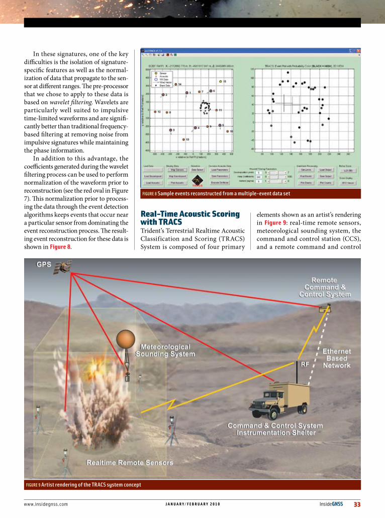
In these signatures, one of the key difficulties is the isolation of signature-specific features as well as the normal-ization of data that propagate to the sen-sor at different ranges. The pre-processor that we chose to apply to these data is based on wavelet filtering. Wavelets are particularly well suited to impulsive time-limited waveforms and are signifi-cantly better than traditional frequency-based filtering at removing noise from impulsive signatures while maintaining the phase information.
In addition to this advantage, the coefficients generated during the wavelet filtering process can be used to perform normalization of the waveform prior to reconstruction (see the red oval in Figure 7). This normalization prior to process-ing the data through the event detection algorithms keeps events that occur near a particular sensor from dominating the event reconstruction process. The result-ing event reconstruction for these data is shown in figure 8.
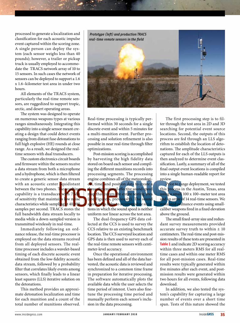
Real-TimeacousticScoringwithTRacSTrident’s Terrestrial Realtime Acoustic Classification and Scoring (TRACS) System is composed of four primary
elements shown as an artist’s rendering in figure 9: real-time remote sensors, meteorological sounding system, the command and control station (CCS), and a remote command and control
FIGURE 8 Sample events reconstructed from a multiple-event data set
FIGURE 9 Artist rendering of the TRACS system concept

34 InsideGNSS j a n u a r y / f e b r u a r y 2 0 1 0 www.insidegnss.com
station (RCCS). Accompanying photos show the CCS and the truck/trailer unit that houses it.
TRACS employs GPS technology in each of these elements for precise posi-tioning and timing, which is critical to the development of absolute WGS-84 coordinates and coordinated universal
time (UTC) timing for scoring munition detonations. A typical test scenario calls for numerous real-time remote sensors, which incorporate a 12-channel OEM GPS receiver board, to be deployed across test areas that can vary in size by as much as 6.4 kilometers.
System components communicate
wirelessly using a 900MHz RF network capable of distributing real-time compo-nent health and status, GPS position and tracking information, and acoustic data to multiple sources. The primary recipi-ent of this data is the CCS, although the data is also retransmitted to the RCCS in the event that the primary CCS cannot be staffed physically. The RCCS is fully mission-capable and can support all sys-tem operations as long as the facility is linked by RF or fiber-optic communica-tions with the CCS.
The TRACS system has the ability to perform real-time health checks across the network of sensors to ensure that the system is ready for data capture or to alert an operator to a failed segment. The system also has replaced previously required manual surveys with a GPS-based self-surveying capability, reduc-ing installation and setup time and labor. Each real-time remote sensor also monitors its GPS–based survey position so that it can warn the operator in the event of significant displacement due to such factors as high winds or a near-field ordnance detonation.
The real-time acoustic data can be audibly and visually reviewed as well as
acouSTicSandgpS
The TRACS system command and control center (top) and the vehicle that houses it
www.insidegnss.com j a n u a r y / f e b r u a r y 2 0 1 0 InsideGNSS 35
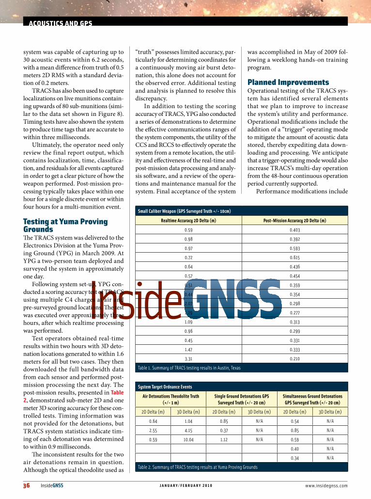
processed to generate a localization and classification for each acoustic impulse event captured within the scoring zone. A single person can deploy the sys-tem (each sensor weighs less than 40 pounds); however, a trailer or pickup truck is usually employed to accommo-date the TRACS network array of 10 to 15 sensors. In such cases the network of sensors can be deployed to support a 1.6 x 1.6–kilometer test area in under two hours.
All elements of the TRACS system, particularly the real-time remote sen-sors, are ruggedized to support tropic, arctic, and desert operating areas.
The system was designed to operate on numerous weapons types at various ranges simultaneously. Integrating this capability into a single sensor meant cre-ating a design that could detect events ranging from distant fuse detonations to full high explosive (HE) rounds at close range. As a result, we designed the real-time sensors with dual transducers.
The custom electronics circuit boards and firmware within the sensors receive a data stream from both a microphone and a hydrophone, which is then filtered to create a generic sensor data stream with an acoustic center equidistant between the two phones. The resulting capability is a transducer with 75dB of sensitivity that maintains low noise characteristics while sampling at 40,000 samples per second. TRACS stores the full bandwidth data stream locally to media while a down-sampled version is transmitted wirelessly in real-time.
Immediately following an ord-nance release, the real-time processor is employed on the data streams received from all deployed sensors. The real-time processor includes a wavelet-based timing of each discrete acoustic event obtained from the low-fidelity acoustic data stream, followed by a probability filter that correlates likely events among sensors, which finally leads to a linear least squares (LLS) iterative solution on the detonations.
This method provides an approxi-mate detonation localization and time for each munition and a count of the total number of munitions observed.
Real-time processing is typically per-formed within 30 seconds for a single discrete event and within 5 minutes for a multi-munition event. Further pro-cessing and solution refinement is also possible in near real-time through filter optimizations.
Post-mission scoring is accomplished by harvesting the high fidelity data stored on board each sensor and compil-ing the different munitions records into processing segments. The processing engine combines all of the meteorologi-cal, time, and position data to create a three-dimensional effective sound speed map that covers the entire testing area (see Figure 6, previously). The sound speed maps helps to accommodate situa-tions in which the sound speed is neither uniform nor linear across the test area.
The dual-frequency GPS data col-lected at the CCS is used to survey the CCS relative to an existing benchmark location. The CCS surveyed location and GPS data is then used to survey each of the real-time remote sensors with centi-meter-level accuracy.
Once the operational environment has been defined and all of the data har-vested, the acoustic data is reviewed and synchronized to a common time frame in preparation for iterative processing. The software automatically plots the available data while the user selects the time period of interest. Users also fine-tune the processing time period and manually perform each sensor’s inclu-sion in the data processing.
The first processing step is to fil-ter through the test area in 2D and 3D searching for potential event source locations. Second, the outputs of this process are fed through an LLS algo-rithm to establish the location of deto-nations. The amplitude characteristics captured for each of the LLS outputs is then analyzed to determine event clas-sification. Lastly, a summary of all of the final output event locations is compiled into a single human-readable report for review.
Prior to range deployment, we tested this process in the Austin, Texas, area using a small 100 x 100–meter test area and an array of 14 real-time sensors. We simulated ordnance events using small-caliber weapons fired in a fixed elevation above the ground.
The small fixed-array size and redun-dant survey measurements provided accurate survey truth to within ± 10 centimeters. The real-time and post-mis-sion results of these tests are presented in Table 1 and indicate 2D scoring accuracy within three meters RMS for all real-time cases and within one meter RMS for all post-mission cases. Real-time results were typically generated within five minutes after each event, and post-mission results were generated within two hours for all events, following data download.
In addition, we also tested the sys-tem’s capability for capturing a large number of events over a short time span. Tests of this nature showed the
Prototype (left) and production TRACS real-time remote sensors in the field
36 InsideGNSS j a n u a r y / f e b r u a r y 2 0 1 0 www.insidegnss.com
system was capable of capturing up to 30 acoustic events within 6.2 seconds, with a mean difference from truth of 0.5 meters 2D RMS with a standard devia-tion of 0.2 meters.
TRACS has also been used to capture localizations on live munitions contain-ing upwards of 80 sub-munitions (simi-lar to the data set shown in Figure 8). Timing tests have also shown the system to produce time tags that are accurate to within three milliseconds.
Ultimately, the operator need only review the final report output, which contains localization, time, classifica-tion, and residuals for all events captured in order to get a clear picture of how the weapon performed. Post-mission pro-cessing typically takes place within one hour for a single discrete event or within four hours for a multi-munition event.
TestingatYumaprovinggroundsThe TRACS system was delivered to the Electronics Division at the Yuma Prov-ing Ground (YPG) in March 2009. At YPG a two-person team deployed and surveyed the system in approximately one day.
Following system set-up, YPG con-ducted a scoring accuracy test of TRACS using multiple C4 charges at air and pre-surveyed ground locations. The test was executed over approximately three hours, after which realtime processing was performed.
Test operators obtained real-time results within two hours with 3D deto-nation locations generated to within 1.6 meters for all but two cases. They then downloaded the full bandwidth data from each sensor and performed post-mission processing the next day. The post-mission results, presented in Table 2, demonstrated sub-meter 2D and one meter 3D scoring accuracy for these con-trolled tests. Timing information was not provided for the detonations, but TRACS system statistics indicate tim-ing of each detonation was determined to within 0.9 milliseconds.
The inconsistent results for the two air detonations remain in question. Although the optical theodolite used as
“truth” possesses limited accuracy, par-ticularly for determining coordinates for a continuously moving air burst deto-nation, this alone does not account for the observed error. Additional testing and analysis is planned to resolve this discrepancy.
In addition to testing the scoring accuracy of TRACS, YPG also conducted a series of demonstrations to determine the effective communications ranges of the system components, the utility of the CCS and RCCS to effectively operate the system from a remote location, the util-ity and effectiveness of the real-time and post-mission data processing and analy-sis software, and a review of the opera-tions and maintenance manual for the system. Final acceptance of the system
was accomplished in May of 2009 fol-lowing a weeklong hands-on training program.
plannedimprovementsOperational testing of the TRACS sys-tem has identified several elements that we plan to improve to increase the system’s utility and performance. Operational modifications include the addition of a “trigger” operating mode to mitigate the amount of acoustic data stored, thereby expediting data down-loading and processing. We anticipate that a trigger-operating mode would also increase TRACS’s multi-day operation from the 48-hour continuous operation period currently supported.
Performance modifications include
acouSTicSandgpS
Small Caliber Weapon (GPS Surveyed Truth +/- 10cm)
Realtime Accuracy 2D Delta (m) Post-Mission Accuracy 2D Delta (m)
0.59 0.403
0.98 0.392
0.97 0.593
0.72 0.615
0.64 0.436
0.57 0.454
0.51 0.359
0.44 0.354
2.07 0.298
1.29 0.277
1.09 0.313
0.96 0.299
0.45 0.331
1.47 0.333
3.31 0.210
Table1.SummaryofTRACStestingresultsinAustin,Texas
System Target Ordnance Events
Air Detonations Theodolite Truth (+/- 1 m)
Single Ground Detonations GPS Surveyed Truth (+/- 20 cm)
Simultaneous Ground Detonations GPS Surveyed Truth (+/- 20 cm)
2DDelta(m) 3DDelta(m) 2DDelta(m) 3DDelta(m) 2DDelta(m) 3DDelta(m)
0.64 1.04 0.85 N/A 0.54 N/A
2.55 4.15 0.37 N/A 0.85 N/A
0.59 10.04 1.12 N/A 0.59 N/A
0.40 N/A
0.34 N/A
Table2.SummaryofTRACStestingresultsatYumaProvingGrounds

www.insidegnss.com j a n u a r y / f e b r u a r y 2 0 1 0 InsideGNSS 37
the modeling and filtering of supersonic acoustic events to improve the ability of the wavelet processor to identify lead-ing edge signatures and thus improve the 3D scoring accuracy of air burst detonations. Another performance modification under study is the ability to discriminate unique acoustic events for dispensed munitions where significant numbers of munitions are detonated in a small spatial and temporal area.
Two likely concept of operations modifications that would improve the ability to localize each unique dispensed munition event: altering sensor place-ment to significantly vary the range of each sensor relative to the impact field and reducing the temporal spacing within the LLS algorithm. These pend-ing modifications will expand the utility of the system and improve scoring reli-ability and accuracy.
conclusionTrident Research has adapted its TARGT ocean-based acoustic scoring system technology — described in an Inside GNSS article (August 2006) — to suc-cessfully provide sub-meter 2D and one-meter 3D munition scoring in a land-based environment. The TRACS system provides a highly portable, one-person deployable, land-based capability for the accurate scoring of single and multiple ground- and air-burst munitions.
The system has been accepted and successfully used by the U.S. Army Yuma Proving Ground to support weapons testing of multiple types of military ord-nance. This off-the-shelf capability pro-vides a rapid and low-cost alternative to conventional weapons testing methods. TRACS is highly adaptable to a broad range of test environments and provides a new tool for weapons program offices in evaluating the performance of new weapons, particularly weapons using dispensed submunitions.
ManufacturersThe TRACS real-time remote sensor incorporates the AC12 GPS receiver from Ashtech SAS, Carquefou, France; a Wi-Sys WS3977-DH GPS antenna from PCTEL, Inc., Bloomingdale, Illi-nois, USA; an AW900mT RF Trans-ceiver from AvaLAN Wireless Systems, Inc., Madison, Alabama, USA; an A09-HASM-675, MaxStream, Inc., Lindon, Utah, USA; a WXT-510 MET Sensor from Vaisala Oyj, Helsinki, Finland; an SDCFX3-16384-901 Extreme III 15GB CF card from SanDisk Corporation, Milpitas, California, USA; an MPA205 microphone, BSWA Technology Co., Ltd., Beijing, China; and a SensorTech SQ21 hydrophone, Sensor Technology Ltd., Collingwood, Ontario, Canada.
The TRACS instrumentation shel-ter contains a DL-V3 GPS/GLONASS receiver and a GPS-702-GG antenna manufactured by NovAtel, Inc., Calgary, Alberta, Canada; an AvaLAN Wire-less AW900xT radio; and an Antenex FG9026 RF antenna from Laird Tech-nologies, Chesterfield, Missouri, USA.
The TRACS remote command and control system incorporates a TR2021 computer (comprising an Intel Core 2 Duo 2.4 GHz; 4GB PC2 8500; 250 GB Storage; DVD+R) from Trident Research LLC, Austin, Texas, USA; an AW900xT radio and AW15 Yagi antenna from AvaLAN Wireless Systems, Inc.
authorsMiguel A. Cardoza hasworkedformorethan25yearsinsystemsengi-neering and programmanagementforfederal,state,andforeigngov-ernments in both the
universityandprivateindustrysectors.Inthattimehehasledthedesign,development,andfieldingofmultipleinstrumentationsystemsintheareaofweaponstestingandtraining,withemphasisonreal-time,remote,distributedsensorsystems.Cardozareceivedhisbachelorandmas-
terdegreesofscienceinaerospaceengineeringfromtheUniversityofTexasatAustin,andisagraduateoftheAdvancedProgramManagementCoursefromtheDefenseSystemsManagementCollege,atFortBelvoir,Virginia.Hehasauthorednumeroustechnicalpapersandpatentsonreal-timemilitaryinstrumentationsystemsandisthefounderandpresidentofTridentResearchLLC.
Dr. Jeffrey A Cook hasdevelopedprototypesoftacticalandinstrumen-tationsystemsforreal-timeenvironmentalsur-v e i l l a n c e , r e m o t esensing,datatelemetry,
automatedclassification,andcasualtyassessmentformultiplefederalandstategovernments.Hehasdevelopedandvalidatedfieldprototypesys-temsforballisticmissileandair-droppedbombscoring.Cookhasdesigned,fabricated,anddem-onstrated“sparker”-basedacousticsources,includinggeophysical-scaleunitsandsmallunitsforsimulationtestingofbombscoringsystems.CookwastheleadscientistfortheTRACSsystemdevelopmentforU.S.ArmyYumaProvingGround.HereceivedhisPh.D.inphysicsfromtheUniver-sityofTexasatAustinandiscurrentlyaseniorresearchscientistforTridentResearchLLC.
William Adamez hasworkedformorethan10yearsinsoftwareengi-neeringandITmanage-mentfortheDepartmentofDefenseinboththeuniversityandprivate
industrysectors.Inthattimehehasparticipatedinthedesign,development,andfieldingofanumberofmilitaryinstrumentationsystemsfortheU.S.Navy,Army,andAirForce.AdamezwastheprojectleadfortheTRACSsystemdevelop-mentfortheU.S.ArmyYumaProvingGround.Hereceivedhisbachelorofartsdegreeingeograph-icinformationsciencesfromtheUniversityofTexasatAustinandhismastersofSciencedegreeinmanagementinformationsystemsfromtheUniversityofPhoenix.Hehasalsoco-authoredpatentsonreal-timemilitaryinstrumentationsystemsandispresentlyaseniorsoftwareengi-neeratTridentResearchLLC.