acquity qda detector - waters corporation€¦ · · 2014-12-01acquity qda detector overview and...
TRANSCRIPT
ACQUITY QDa DetectorOverview and Maintenance Guide
715003956 Revision B
Copyright © Waters Corporation 2014All rights reserved

ii 13 November, 2014, 715003956 Rev. B

General Information
Copyright notice
© 2014 WATERS CORPORATION. PRINTED IN THE UNITED STATES OF AMERICA AND IN IRELAND. ALL RIGHTS RESERVED. THIS DOCUMENT OR PARTS THEREOF MAY NOT BE REPRODUCED IN ANY FORM WITHOUT THE WRITTEN PERMISSION OF THE PUBLISHER.
The information in this document is subject to change without notice and should not be construed as a commitment by Waters Corporation. Waters Corporation assumes no responsibility for any errors that may appear in this document. This document is believed to be complete and accurate at the time of publication. In no event shall Waters Corporation be liable for incidental or consequential damages in connection with, or arising from, its use. For the most recent revision of this document, consult the Waters Web site (waters.com).
Trademarks
Waters, ACQUITY, Connections INSIGHT, “THE SCIENCE OF WHAT’S POSSIBLE.”, and Waters Quality Parts, are registered trademarks of Waters Corporation. QDa and RADAR are trademarks of Waters Corporation.
PEEK is a registered trademark of Victrex Manufacturing, Limited.
Tygon is a registered trademark of Saint-Gobain Corporation.
Viton is a registered trademark of Dupont Dow Elastomers.
Other registered trademarks or trademarks are the sole property of their owners.
13 November, 2014, 715003956 Rev. B iii

Customer comments
Waters’ Technical Communications organization invites you to report any errors that you encounter in this document or to suggest ideas for otherwise improving it. Help us better understand what you expect from our documentation so that we can continuously improve its accuracy and usability.
We seriously consider every customer comment we receive. You can reach us at [email protected].
Contacting Waters
Contact Waters® with enhancement requests or technical questions regarding the use, transportation, removal, or disposal of any Waters product. You can reach us via the Internet, telephone, or conventional mail.
Waters contact information:
Contacting medium Information
Internet The Waters Web site includes contact information for Waters locations worldwide. Visit www.waters.com.
Telephone and fax From the USA or Canada, phone 800 252-4752, or fax 508 872 1990.For other locations worldwide, phone and fax numbers appear in the Waters Web site.
Conventional mail Waters Corporation34 Maple StreetMilford, MA 01757USA
iv 13 November, 2014, 715003956 Rev. B

Safety considerations
Some reagents and samples used with Waters instruments and devices can pose chemical, biological, or radiological hazards (or any combination thereof). You must know the potentially hazardous effects of all substances you work with. Always follow Good Laboratory Practice, and consult your organization’s standard operating procedures.
Considerations specific to the ACQUITY QDa Detector
Solvent leakage hazard
The source exhaust system is designed to be robust and leak-tight. Waters recommends you perform a hazard analysis, assuming a maximum leak into the laboratory atmosphere of 10% LC eluate, with an additional 0.5% leak for the Standard instrument.
Warning: To avoid leaks of materials that are biohazardous or toxins, follow these guidelines:• To confirm the integrity of the source exhaust system, renew
the source O-rings at intervals not exceeding one year.• To avoid chemical degradation of the source O-rings, which can
withstand exposure only to certain solvents (see page 76), determine whether any solvents you use that are not listed are chemically compatible with the composition of the O-rings.
13 November, 2014, 715003956 Rev. B v

Flammable solvents hazard
High temperature hazard
Mass spectrometer high temperature hazard:
Warning: To prevent ignition of flammable solvent vapors in the enclosed space of a mass spectrometer’s ion source, ensure that nitrogen flows continuously through the source. The nitrogen supply pressure must not fall below 600 kPa (6.0 bar, 87 psi) during an analysis requiring the use of flammable solvents.
Warning: To avoid burn injuries, avoid touching the source enclosure when operating or servicing the instrument.
Source enclosure assembly
vi 13 November, 2014, 715003956 Rev. B

High voltage hazard
Hazards associated with removing an instrument from service
When you remove the instrument from use to repair or dispose of it, you must decontaminate all of its vacuum areas. These are the areas in which you can expect to encounter the highest levels of contamination:
• Source interior
• Waste tubing
• Exhaust system
• Rotary pump oil (where applicable)
The need to decontaminate other vacuum areas of the instrument depends on the kinds of samples the instrument analyzed and their levels of concentration. Do not dispose of the instrument or return it to Waters for repair until the authority responsible for approving its removal from the premises specifies the extent of decontamination required and the level of residual contamination permissible. That authority must also prescribe the method of decontamination to be used and the appropriate protection for personnel undertaking the decontamination process.
You must handle items such as syringes, fused silica lines, and borosilicate tips used to carry sample into the source area in accordance with laboratory procedures for contaminated vessels and sharps. To avoid contamination by
Warning:
• To avoid electric shock, do not remove the mass spectrometer’s protective panels. The components they cover are not user-serviceable.
• To avoid nonlethal electric shock when the instrument is switched on, avoid touching the areas marked with the high voltage warning symbol. To touch those areas, first switch the instrument off.
Warning: To avoid personal contamination with biohazards, toxic materials, and corrosive materials, wear chemical-resistant gloves during all phases of instrument decontamination.
Warning: To avoid puncture injuries, handle syringes, fused silica lines, and borosilicate tips with extreme care.
13 November, 2014, 715003956 Rev. B vii

carcinogens, toxic substances, or biohazards, you must wear chemical-resistant gloves when handling or disposing of used oil.
FCC radiation emissions notice
Changes or modifications not expressly approved by the party responsible for compliance, could void the users authority to operate the equipment. This device complies with Part 15 of the FCC Rules. Operation is subject to the following two conditions: (1) this device may not cause harmful interference, and (2) this device must accept any interference received, including interference that may cause undesired operation.
Canada spectrum management emissions notice
This class A digital product apparatus complies with Canadian ICES-003.
Cet appareil numérique de la classe A est conforme à la norme NMB-003.
Electrical power safety notice
Do not position the instrument so that it is difficult to disconnect the power cord.
Safety hazard symbol notice
Documentation needs to be consulted in all cases where the symbol is used to find out the nature of the potential hazard and any actions which have to be taken.
Equipment misuse notice
If the equipment is used in a manner not specified by the manufacturer, the protection provided by the equipment may be impaired.
Safety advisories
Consult Appendix A for a comprehensive list of warning and caution advisories.
viii 13 November, 2014, 715003956 Rev. B
Operating this instrument
When operating this instrument, follow standard quality-control (QC) procedures and the guidelines presented in this section.
Applicable symbols
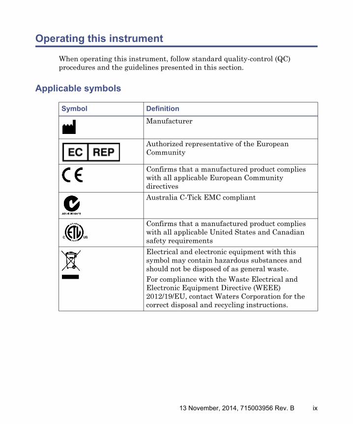
Symbol Definition
Manufacturer
Authorized representative of the European Community
Confirms that a manufactured product complies with all applicable European Community directives
Australia C-Tick EMC compliant
Confirms that a manufactured product complies with all applicable United States and Canadian safety requirements
Electrical and electronic equipment with this symbol may contain hazardous substances and should not be disposed of as general waste.For compliance with the Waste Electrical and Electronic Equipment Directive (WEEE) 2012/19/EU, contact Waters Corporation for the correct disposal and recycling instructions.
13 November, 2014, 715003956 Rev. B ix

Audience and purpose
This guide is for novice users, and assumes no knowledge of liquid chromatography or mass spectrometry principles. It provides an overview of the instrument and explains how to install it, prepare it for operation, and maintain it.
Intended use of the ACQUITY QDa Detector
Waters designed the ACQUITY QDa Detector for use as an ion confirmation and quantitation tool, as part of an ACQUITY UPLC or UPC2 system. The ACQUITY QDa Detector is not intended for use in diagnostic applications.
Calibrating
To calibrate LC systems, follow acceptable calibration methods using at least five standards to generate a standard curve. The concentration range for standards should include the entire range of QC samples, typical specimens, and atypical specimens.
Quality-control
Routinely run three QC samples that represent subnormal, normal, and above-normal levels of a compound. Ensure that QC sample results fall within an acceptable range, and evaluate precision from day to day and run to run. Data collected when QC samples are out of range might not be valid. Do not report these data until you are certain that the instrument performs satisfactorily.
x 13 November, 2014, 715003956 Rev. B

ISM classification
ISM Classification: ISM Group 1 Class A
This classification has been assigned in accordance with IEC CISPR 11 Industrial Scientific and Medical (ISM) instruments requirements. Group 1 products apply to intentionally generated and/or used conductively coupled radio-frequency energy that is necessary for the internal functioning of the equipment.
Class A products are suitable for use in all establishments other than residential locations and those directly connected to a low voltage, power-supply network supplying a building for domestic purposes.
There may be difficulties in ensuring electromagnetic compatibility in other environments due to conducted as well as radiated disturbances.
EC authorized representative
Waters Corporation Stamford AvenueAltrincham RoadWilmslow SK9 4AXUnited Kingdom
Telephone: +44-161-946-2400
Fax: +44-161-946-2480
Contact: Quality manager
13 November, 2014, 715003956 Rev. B xi

xii 13 November, 2014, 715003956 Rev. B
Table of Contents
General Information .................................................................................... iii
Copyright notice .................................................................................................. iii
Trademarks ........................................................................................................... iii
Customer comments ............................................................................................ iv
Contacting Waters ............................................................................................... iv
Safety considerations ........................................................................................... v Considerations specific to the ACQUITY QDa Detector ................................... v FCC radiation emissions notice ...................................................................... viii Canada spectrum management emissions notice .......................................... viii Electrical power safety notice ......................................................................... viii Safety hazard symbol notice............................................................................ viii Equipment misuse notice ................................................................................ viii Safety advisories .............................................................................................. viii
Operating this instrument ................................................................................. ix Applicable symbols ............................................................................................. ix Audience and purpose.......................................................................................... x Intended use of the ACQUITY QDa Detector .................................................... x Calibrating ........................................................................................................... x Quality-control ..................................................................................................... x
ISM classification ................................................................................................. xi ISM Classification: ISM Group 1 Class A ......................................................... xi
13 November, 2014, 715003956 Rev. B xiii

EC authorized representative ........................................................................... xi
1 Instrument features and Operating Modes ...................................... 17
Operating modes ................................................................................................ 18
Ion optics .............................................................................................................. 18
Auto setup ............................................................................................................ 19
Sample inlet ......................................................................................................... 19
Vacuum system ................................................................................................... 19
2 Preparing for Operation ....................................................................... 21
Rear panel connections .................................................................................... 22
Connecting to the electricity source ............................................................. 22
Starting the instrument ................................................................................... 23
3 Maintenance Procedures ...................................................................... 25
Spare parts .......................................................................................................... 26
Replacing fuses ................................................................................................... 26
Troubleshooting using Connections INSIGHT ........................................... 26
Safety and handling .......................................................................................... 28
Removing and refitting the source enclosure ............................................. 29 Removing the source enclosure from the instrument ...................................... 29 Fitting the source enclosure to the instrument................................................ 30
Maintaining the source components ............................................................. 31 Removing the sample cone assembly from the ion block................................. 31 Replacing the entrance-aperture seal and disc ................................................ 34 Removing the ion block...................................................................................... 35 Cleaning the source components....................................................................... 37 Refitting the source components....................................................................... 38
Cleaning the ion guide assembly .................................................................... 40 Removing the ion guide assembly from the source assembly.......................... 40
xiv 13 November, 2014, 715003956 Rev. B

Cleaning the differential aperture.................................................................... 44 Cleaning the ion guide assembly ...................................................................... 46 Fitting the ion guide assembly to the instrument ........................................... 48
Emptying the nitrogen exhaust trap ............................................................. 52
Replacing the roughing pump’s oil ................................................................ 54
A Safety Advisories .................................................................................... 57
Warning symbols ................................................................................................ 58 Specific warnings ............................................................................................... 59
Notices .................................................................................................................. 61
Warnings that apply to all Waters instruments and devices ................... 62
Warnings that address the replacing of fuses ............................................. 67
Electrical and handling symbols .................................................................... 69 Electrical symbols .............................................................................................. 69 Handling symbols .............................................................................................. 70
13 November, 2014, 715003956 Rev. B xv

B Specifications .......................................................................................... 71
Physical specifications ..................................................................................... 72
Environmental specifications ......................................................................... 72
Electrical specifications ................................................................................... 73
Input/output specifications ............................................................................. 74
C Materials of Construction and Compatible Solvents ..................... 75
Preventing contamination ............................................................................... 76
Items exposed to solvent .................................................................................. 76
Solvents used to prepare mobile phases ...................................................... 77
D External Connections ............................................................................ 79
External wiring and vacuum connections ................................................... 80
Connecting the Standard instrument’s backing pump ............................. 81
Connecting the Performance instrument’s backing pump ...................... 82 Making the electrical connections to the rotary pump .................................... 85
Connecting to the nitrogen gas supply ......................................................... 86
Connecting the nitrogen exhaust line .......................................................... 87 Connecting the exhaust solenoid cable............................................................. 90
Connecting the workstation ............................................................................ 90
Connecting Ethernet cables ............................................................................ 91
Input/output signal connectors ...................................................................... 92 Signal connections ............................................................................................. 93
Connecting to the power supply .................................................................... 95
xvi 13 November, 2014, 715003956 Rev. B

1 Instrument features and Operating Modes
To effectively use the ACQUITY® QDa™ Detector, you must familiarize yourself with its operating modes and feature.
Contents:
Topic Page
Operating modes .............................................................................. 18
Ion optics .......................................................................................... 18
Auto setup ........................................................................................ 19
Sample inlet ..................................................................................... 19
Vacuum system ................................................................................ 19
13 November, 2014, 715003956 Rev. B 17

1 Instrument features and Operating Modes
Operating modes
You can acquire data using any of these operating modes:
• Scanning, where the instrument scans across a user-defined span of mass-to-charge (m/z) ratios to produce a mass spectrum.
• Selected ion recording (SIR), where the instrument records the signal intensity at a static m/z ratio for the purpose of quantitation. Multiple m/z ratios can be recorded simultaneously.
• MSe, where the instrument performs both low and high fragmentation energy scans in a single run to aid in compound identification.
• RADAR, where the instrument performs Scanning and SIR acquisitions simultaneously.
Important: Do not open the instrument’s front door during data acquisition. Doing so cancels the acquisition.
Ion optics
Ions flow through the instrument in the following sequence:
1. Samples from the LC are introduced into the ionization source.
2. The ions pass through the sample cone into the vacuum system.
3. The ions pass through the transfer optics (the ion guides) to the quadrupole, where they are filtered according to their m/z ratios.
4. The transmitted ions are detected by the photomultiplier detection system.
5. The signal is amplified, digitized, and sent to the software for analysis.
18 13 November, 2014, 715003956 Rev. B

Auto setup
Auto setup
The instrument can perform auto setup checks when it powers on. If auto setup is enabled, the instrument performs a startup check of mass scale calibration and quadrupole (spectrum) resolution, using an internal calibrant during startup. If the instrument reports no problems, the status LED shows green, and the instrument is ready for use. If the check identifies a problem, the software prompts you to start an automatic correction process. The quadrupole resolution and mass scale calibration can also be checked on demand without powering off the instrument.
To learn how to enable startup checks, see the instrument’s online Help.
Sample inlet
Connect the ACQUITY QDa to the preceding instrument in your system using the supplied probe assembly. You can use 250-mm or 500-mm probe assemblies, whichever best suits your configuration. If required, use a union to extend the length to fit with your configuration.
Recommendation: Where possible, use the 250-mm PEEK tubing. Doing so minimizes band broadening.
Vacuum system
An internal turbomolecular pump and external backing pump create the instrument’s vacuum. The Performance instrument uses a separate rotary vane pump, and the Standard instrument uses a diaphragm pump attached to the back of the instrument.
Vacuum leaks, electrical failures, and vacuum pump failures cause vacuum loss, the damage from which is prevented by protective interlocks. The system monitors turbomolecular pump speed and continuously measures turbo power. The turbo speed also serves as a switch, stopping operation when it senses vacuum loss.
Notice: Ensure suitable tubing is used to prevent the pressure exceeding the limits of the preceding instruments.
13 November, 2014, 715003956 Rev. B 19

1 Instrument features and Operating Modes
20 13 November, 2014, 715003956 Rev. B
2 Preparing for Operation
Prepare the detector for use according to the specifications in this chapter.
Contents:
Topic Page
Rear panel connections .................................................................... 22
Connecting to the electricity source ................................................ 22
Starting the instrument .................................................................. 23
13 November, 2014, 715003956 Rev. B 21

2 Preparing for Operation
Rear panel connections
When making connections to the QDa detector’s rear panel, refer to the diagram in Appendix D, “External Connections”.
For details of supported inlet system configurations, contact Waters Technical Service.
Connecting to the electricity source
The ACQUITY QDa requires a separate, grounded (earthed) electricity source. The ground connection in the electrical outlet must be common and connected near the system.
To connect to the electricity source:
Recommendation: Use a line conditioner and uninterruptible power supply (UPS) for optimum long-term input voltage.
1. Connect the female end of the power cord to the receptacle on the rear panel of the detector.
2. Connect the male end of the power cord to a suitable wall outlet.
Alternative: If your system includes the optional FlexCart, connect the female end of the cart’s electrical cable (included in the startup kit) to the receptacle on the rear panel of the instrument. Connect the hooded, male end of the cart’s electrical cable to the power strip on the back of the cart. Finally, connect the power strip’s cable to a wall outlet operating on its own circuit.
Warning: To avoid electrical shock, observe these precautions:• Use the SVT-type power cord in the United States and the HAR-type
(or better) in Europe. The main power cord must be replaced with one of adequate rating. To learn which cord to use in other countries, contact your local Waters® distributor.
• Power-off and unplug the detector before performing any maintenance on the instrument.
• Connect all components of the ACQUITY inlet system to a common ground.
22 13 November, 2014, 715003956 Rev. B

Starting the instrument
Starting the instrument
Starting the instrument entails powering-on the ACQUITY workstation, logging into the workstation, powering-on the instrument and all other ACQUITY instruments, and starting the software.
Requirement: You must power-on and log in to the ACQUITY UPLC workstation first to ensure that it obtains the IP addresses of the system instruments.
To start the instrument:
1. On the rear panel, ensure the nitrogen supply is connected to the instrument’s nitrogen inlet connection (see page 22).
Requirement: The nitrogen must be dry and oil-free, with a purity of at least 95%. Regulate the supply at 600 to 690 kPa (6.0 to 6.9 bar, 87 to 100 psi).
2. Power-on the workstation, and log in.
3. Press the power switches on the top, left-hand sides of the ACQUITY system modules, including the QDa detector.
Result: Each module establishes communications with the workstation.
Warning: To avoid electric shock and burn injuries, follow these guidelines:• Do not expose the data system or any ancillary equipment to
dripping or splashing liquids.• Do not place objects filled with liquid, such as solvent bottles, on
the data system or ancillary equipment.
Notice: To avoid damage to the instrument caused by incompatible solvents, refer to Appendix C, “Materials of Construction and Compatible Solvents”.
Warning: To avoid igniting flammable solvents, never let the nitrogen supply pressure fall below 600 kPa (6.0 bar, 87 psi).
13 November, 2014, 715003956 Rev. B 23

2 Preparing for Operation
4. Allow approximately 5 minutes for the instruments to establish communications.
Tip: The power and status LEDs show steady green when the instruments have established communications.
5. On the workstation, start the software.
Result: The instrument performs startup checks.
6. In the software, monitor the Instrument Console for messages and LED indications.
24 13 November, 2014, 715003956 Rev. B

3 Maintenance Procedures
Keep to a maintenance schedule, and perform maintenance as required and described in this chapter.
Contents:
Topic Page
Spare parts ....................................................................................... 26
Replacing fuses................................................................................. 26
Troubleshooting using Connections INSIGHT............................... 26
Safety and handling......................................................................... 28
Removing and refitting the source enclosure ................................. 29
Maintaining the source components ............................................... 31
Cleaning the ion guide assembly..................................................... 40
Emptying the nitrogen exhaust trap .............................................. 52
Replacing the roughing pump’s oil.................................................. 54
13 November, 2014, 715003956 Rev. B 25

3 Maintenance Procedures
Spare parts
To ensure that your system operates as designed, use only Waters Quality Parts®. Visit www.waters.com/wqp for information about Waters Quality Parts, including how to order them.
Replacing fuses
If either of the instrument's fuses, located on the rear panel, rupture or become otherwise faulty, replace it with a fuse of this type and rating.
Troubleshooting using Connections INSIGHT
Connections INSIGHT® is an “intelligent” device management (IDM) Web service that enables Waters to provide proactive service and support for the ACQUITY UPLC system. To use Connections INSIGHT, you must install its service agent software on your MassLynx workstation. In a client/server system, you must also install the service agent, on the computer from which you control the system. The service agent software automatically and securely captures and sends information about the support needs of your system directly to Waters.
If you encounter a performance problem when using the Instrument Console, you can manually submit a Connections Insight request to Waters customer
Warning: To protect against fire hazard, replace fuses with those of the type and rating specified in the following table, and printed on the panels adjacent to the instrument’s fuse covers.
Warning: To avoid electric shock, disconnect the mass spectrometer from the power supply before replacing fuses. The instrument has two fuses, and uses double pole/neutral fusing. Circuits can remain live even when one fuse has blown.
Fuse information:
Location Size TypeCurrent rating
Rupture capacity
Voltage rating
Rear panel 5 × 20mm T 8 A H 250 V
26 13 November, 2014, 715003956 Rev. B

Troubleshooting using Connections INSIGHT
support. Alternatively, you can use Remote Desktop, a real-time collaboration option that controls the two-way connection with the ACQUITY UPLC system by enabling the Connections INSIGHT iAssist service level.
Consult these sources for more information about Connections INSIGHT and Connections INSIGHT iAssist:
• http://www.waters.com
• Connections INSIGHT Installation Guide (part number 715001399)
• Connections INSIGHT User's Guide (part number 715001400)
• Your sales representative
• Your local Waters subsidiary
• Waters Customer Support
To submit a Connections Insight request:
1. Select Troubleshoot > Submit Connections Insight request.
2. In the Connections Insight Request dialog box, type your name, telephone number, e-mail address, and a description of the problem.
3. Click Submit, and allow approximately 5 minutes to save the service profile.
Result: A .zip file containing your Connections Insight profile is forwarded to Waters customer support for review.
Tip: Saving a service profile or plot file from the Instrument Console can require as much as 150 MB of file space.
13 November, 2014, 715003956 Rev. B 27

3 Maintenance Procedures
Safety and handling
Bear in mind the following safety considerations when performing maintenance procedures:
See Appendix A for safety advisory information.
Warning: The instrument components can be contaminated with biohazards or toxic materials. Always wear chemical-resistant, powder-free gloves while handling the components.
Warning: To prevent injury, follow these guidelines:• Always observe Good Laboratory Practice when handling solvents,
changing tubing, or operating the instrument. Know the physical and chemical properties of the solvents used (see the Material Safety Data Sheets for the solvents in use).
• Ensure the instrument is fully vented before performing maintenance procedures.
Warning: To avoid electric shock,• do not remove the instrument’s panels, for they cover no
user-serviceable items.• ensure that the instrument is in Standby mode before you begin any
maintenance operation.
Warning: The probe and source can be hot. To avoid burn injuries, take great care while working with these components.
Notice: When performing maintenance operations inside the source enclosure, ensure that these criteria are met:• The instrument is powered-off.• The LC flow is disconnected.
28 13 November, 2014, 715003956 Rev. B
Removing and refitting the source enclosure
Removing and refitting the source enclosure
Remove the source enclosure to gain access to the source components that need routine cleaning and replacement.
Removing the source enclosure from the instrument
Required material
Chemical-resistant, powder-free gloves
To remove the source enclosure:
1. Power-off the instrument using the power button in the top, left-hand corner of the front panel.
2. Wait for approximately 5 minutes, to allow the instrument to vent.
3. Open the source enclosure door.
4. To disconnect the source enclosure’s electrical cable from the front of the instrument, loosen the screws and pull the cable from the socket.
5. Loosen the 2 thumbscrews on the front of the source enclosure.
6. To remove the source enclosure, pull it away from the instrument using both hands.
Warning: The source components can be contaminated with biohazards or toxic materials. Always wear chemical-resistant, powder-free gloves while performing this procedure.
Notice: To avoid damaging the fragile probe, use care when removing it from the source enclosure.
Warning: To avoid burn injuries, allow the source enclosure to cool before touching the metal interior.
13 November, 2014, 715003956 Rev. B 29

3 Maintenance Procedures
7. Remove the probe from the top of the source enclosure using the thumbscrew.
Fitting the source enclosure to the instrument
Required material
Chemical-resistant, powder-free gloves
To fit the source enclosure:
1. Using both hands, slide the source enclosure onto instrument’s supporting rods.
2. To secure the enclosure against the instrument, tighten the 2 thumbscrews on the front of the source enclosure.
3. Connect the electrical cable to the socket on the right-hand side of the instrument’s front panel, and tighten the screws.
4. Carefully insert the probe into the orifice at the top of the source enclosure.
5. To secure the probe, tighten the PEEK screw atop the source enclosure.
Tip: The screw clicks when it is fully secured.
Warning: To avoid puncture injuries from the sharp probe tip, use care when inserting and removing the probe from the source enclosure.
Warning: To avoid personal contamination with biohazards or toxic materials, wear chemical-resistant, powder-free gloves while performing this procedure.
Notice: To avoid damage to the electrical connector’s screws, do not overtighten them.
Notice: To avoid damaging the fragile probe, use care when inserting it into the source enclosure.
30 13 November, 2014, 715003956 Rev. B

Maintaining the source components
Maintaining the source components
Clean the source components when these conditions apply:
• The sample cone and cone gas nozzle are visibly fouled.
• You have dismissed inlet and sample-related causes for decreased signal intensity.
Removing the sample cone assembly from the ion block
Required material
Chemical-resistant, powder-free gloves.
To remove the source components from the ion block:
1. Remove the source enclosure (see page 29).
2. To remove the gas cone and PEEK cone clamp, pull the cone clamp away from the instrument.
Warning: To avoid personal contamination with biohazards or toxic materials, always wear chemical-resistant, powder-free gloves while performing this procedure.
Warning: To avoid burn injuries, allow the ion block to cool before performing this procedure.
13 November, 2014, 715003956 Rev. B 31
3 Maintenance Procedures
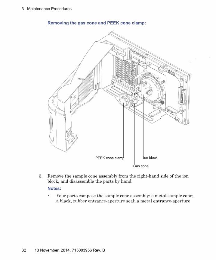
Removing the gas cone and PEEK cone clamp:
3. Remove the sample cone assembly from the right-hand side of the ion block, and disassemble the parts by hand.
Notes:
• Four parts compose the sample cone assembly: a metal sample cone; a black, rubber entrance-aperture seal; a metal entrance-aperture
PEEK cone clamp Ion block
Gas cone
32 13 November, 2014, 715003956 Rev. B
Maintaining the source components
disc, found inside the entrance-aperture seal; a metal entrance-aperture carrier.
• The rubber entrance aperture seal and metal entance-aperture disc are consumables, provided assembled as a single part.
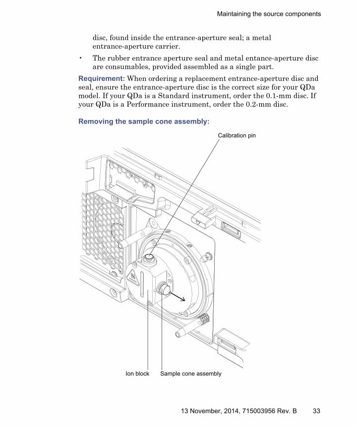
Requirement: When ordering a replacement entrance-aperture disc and seal, ensure the entrance-aperture disc is the correct size for your QDa model. If your QDa is a Standard instrument, order the 0.1-mm disc. If your QDa is a Performance instrument, order the 0.2-mm disc.
Removing the sample cone assembly:
Sample cone assemblyIon block
Calibration pin
13 November, 2014, 715003956 Rev. B 33

3 Maintenance Procedures
Sample cone assembly components:
Replacing the entrance-aperture seal and disc
Replace the entrance seal aperture when these conditions apply:
• You have dismissed LC and sample-related causes for decreased signal intensity.
• Cleaning the source components fails to increase signal stability.
Required materials:
• New entrance-aperture seal and entrance-aperture disc.
• Chemical-resistant, powder-free gloves.
To replace the entrance-aperture seal:
1. Dispose of the old entrance-aperture seal and disc according to your local environmental regulations.
2. Insert the new entrance-aperture seal and disc into the sample cone.
Requirement: When ordering a replacement entrance-aperture disc and seal, ensure the entrance-aperture disc is the correct size for your QDa model. If your QDa is a Standard instrument, order the 0.1-mm disc. If your QDa is a Performance instrument, order the 0.2-mm disc.
Warning: To avoid personal contamination with biohazards or toxic materials, always wear chemical-resistant, powder-free gloves while performing this procedure.
Entrance-aperture carrier
Entrance-aperture seal
Sample cone
Entrance-aperture disc
34 13 November, 2014, 715003956 Rev. B

Maintaining the source components
3. Refit the source components (see page 38).
Removing the ion block
Clean the ion block when cleaning the sample cone assembly fails to increase signal sensitivity.
Required materials:
• Chemical-resistant, powder-free gloves.
• 2.5-mm Allen wrench.
To remove the ion block:
1. Remove the calibration pin from the top of the ion block by pulling it upwards.
Tip: To locate the calibration pin, see the diagram on page 33.
2. Remove the sample cone assembly from the right-hand side of the ion block (see page 31).
Warning: To avoid personal contamination with biohazards or toxic materials, always wear chemical-resistant, powder-free gloves while performing this procedure.
Warning: To avoid puncture injuries from the sharp calibration pin, use care when removing it from and replacing it in the ion block.
13 November, 2014, 715003956 Rev. B 35

3 Maintenance Procedures
3. Remove the 2 screws securing the ion block to the instrument using the 2.5-mm Allen wrench, and remove the ion block.
Ion block securing screws Calibration pin
36 13 November, 2014, 715003956 Rev. B

Maintaining the source components
Cleaning the source components
Required materials:
• Chemical-resistant, powder-free gloves.
• Appropriately sized glass vessels in which to completely immerse components when cleaning. Use only glassware not previously cleaned with surfactants.
• HPLC-grade (or better) methanol.
• HPLC-grade (or better) water.
• Formic acid.
• Ultrasonic bath.
• Source of oil-free, inert gas (nitrogen or argon) for drying (air-drying optional).
• Wash bottle containing HPLC-grade (or better) 1:1 methanol/water.
• Large beaker.
To clean the source components:
1. Remove any O-rings from the source components, and remove the insulator for the PEEK calibration pin from the top of the ion block.
2. Immerse the sample cone, entrance-aperture carrier, and ion block in separate glass vessels containing 1:1 methanol/water.
Note: Do not clean the rubber entrance-aperture seal and entrance-aperture disc. Instead, replace these consumables when they are visibly damaged.
Tip: If the components are obviously contaminated, use 45:45:10 methanol/water/formic acid.
3. Place the vessels in the ultrasonic bath for 30 minutes.
Warning: To avoid personal contamination with biohazards or toxic materials, always wear chemical-resistant, powder-free gloves while performing this procedure.
Warning: To avoid contamination with corrosive and toxic formic acid, use a fume hood and suitable protective equipment during this procedure.
13 November, 2014, 715003956 Rev. B 37

3 Maintenance Procedures
4. If you used formic acid in the cleaning solution, do as follows:
a. Rinse the components by immersing them in separate glass vessels containing water, and then place the vessels in the ultrasonic bath for 20 minutes.
b. Remove any residual water from the components by immersing them in glass vessels containing methanol, and then place the vessels in the ultrasonic bath for 10 minutes.
5. Carefully remove the components from the vessels, and blow-dry them with inert, oil-free gas.
6. Inspect each component for persisting contamination, and if contamination is present, do as follows:
a. Use the wash bottle containing 1:1 methanol/water to rinse the component over the large beaker.
b. Blow-dry the component with inert, oil-free gas.
7. Inspect each component for persisting contamination.
Important: If contamination is present on the sample cone or entrance-aperture carrier, dispose of the component, and obtain a new one before reassembling the sampling cone assembly.
Refitting the source components
Required materials:
• Chemical-resistant, powder-free gloves
• 2.5-mm Allen wrench
To refit the source components:
1. If you removed the O-rings from the source components, refit them.
2. Insert the rubber entrance-aperture seal into the sample cone.
3. Insert the entrance-aperture carrier into the entrance-aperture seal and sample cone assembly.
Notice: To avoid recontaminating the components, wear clean, chemical-resistant, powder-free gloves for the rest of this procedure.
38 13 November, 2014, 715003956 Rev. B

Maintaining the source components
4. Insert the entrance-aperture carrier, entrance-aperture seal, and sample cone assembly into the entrance-aperture on the right-hand-side of the ion block.
5. Insert the calibration pin into the top of the ion block.
6. Place the ion block assembly against the ion block support on the front of the instrument, aligning the screw positions.
7. Secure the ion block to the instrument using the 2, 3-mm screws, and tighten the screws using the 2.5-mm Allen wrench.
8. Refit the source enclosure (see page 30).
13 November, 2014, 715003956 Rev. B 39

3 Maintenance Procedures
Cleaning the ion guide assembly
Clean the ion guide assembly when these conditions apply:
• You have dismissed LC and sample-related causes for decreased signal intensity.
• Cleaning the source components fails to increase signal stability.
• Replacing the entrance-aperture seal and disc fails to increase signal stability.
Removing the ion guide assembly from the source assembly
Required materials:
• Chemical-resistant, powder-free gloves
• 3-mm Allen wrench
• 2.5-mm Allen wrench
• Flat-blade screwdriver
Warning: To avoid personal contamination with biohazards or toxic materials, always wear chemical-resistant, powder-free gloves while performing this procedure.
Warning: To avoid puncture injuries from the sharp calibration pin, use care when removing it from and replacing it in the ion block.
Warning: To avoid burn injuries, allow the source enclosure and source components to cool before performing this procedure.
Notice: To avoid damaging the StepWave ion guide assembly, handle it and its components carefully throughout the cleaning procedure. In particular, do not touch the wiring.
40 13 November, 2014, 715003956 Rev. B

Cleaning the ion guide assembly
To remove the ion guide assembly from the source assembly:
1. Remove the source enclosure from the instrument (see page page 29).
2. Remove the source components and the ion block from the instrument (see page 31 and page 34).
3. Remove the 4 screws securing the pumping block to the instrument, using the 3-mm Allen wrench.
4. Carefully pull the pumping block away from the instrument, removing it.
Note: The ion guide assembly is attached to the rear side of the pumping block.
Removing the pumping block and ion guide:
Pumping block securing screws
Pumping block
Ion guide
13 November, 2014, 715003956 Rev. B 41
3 Maintenance Procedures
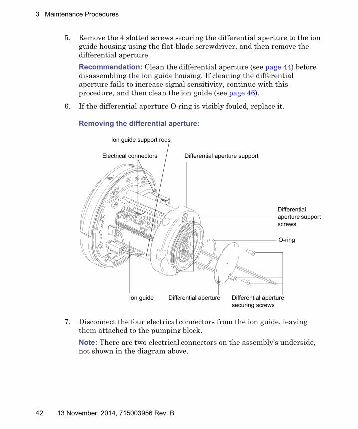
5. Remove the 4 slotted screws securing the differential aperture to the ion guide housing using the flat-blade screwdriver, and then remove the differential aperture.
Recommendation: Clean the differential aperture (see page 44) before disassembling the ion guide housing. If cleaning the differential aperture fails to increase signal sensitivity, continue with this procedure, and then clean the ion guide (see page 46).
6. If the differential aperture O-ring is visibly fouled, replace it.
Removing the differential aperture:
7. Disconnect the four electrical connectors from the ion guide, leaving them attached to the pumping block.
Note: There are two electrical connectors on the assembly’s underside, not shown in the diagram above.
Differential aperture securing screws
Differential aperture Ion guide
O-ring
Differential aperture support
Ion guide support rods
Differential aperture support screws
Electrical connectors
42 13 November, 2014, 715003956 Rev. B

Cleaning the ion guide assembly
8. Remove the 2 screws securing the differential aperture support to the ion guide support rods using the 3-mm Allen wrench, and then remove the differential aperture support and ion guide from the pumping block.
Note: The ion guide is attached to the differential aperture support.
9. To detach the ion guide from the differential aperture support, remove the 4 ion guide securing screws using the 2.5-mm Allen wrench.
Removing the ion guide:
Ion guide securing screws (fourth screw is obscured)
Differential aperture supportIon guide
13 November, 2014, 715003956 Rev. B 43
3 Maintenance Procedures
Cleaning the differential aperture
Required materials:
• Chemical resistant, powder-free gloves.
• Suitable glass vessel in which to completely immerse the differential aperture when cleaning.
• HPLC-grade deionized water.
• Waters MS Cleaning Solution (part number 186006846) or HPLC-grade (or better) 1:1 methanol/water.
• Holding container for used cleaning solution.
• Ultrasonic bath.
• Source of oil-free, inert gas (for example, nitrogen) for drying.
To clean the differential aperture:
1. Place the differential aperture in the glass vessel.
2. Add Waters MS Cleaning Solution or 1:1 methanol/water to the vessel until the differential aperture is immersed completely.
3. Place the vessel containing the differential aperture in the ultrasonic bath for 20 minutes.
4. Carefully pour the cleaning solution from the vessel holding the differential aperture into the holding container, retaining the differential aperture in the vessel.
Tip: You can reuse Waters MS Cleaning Solution for one subsequent cleaning.
5. Fill the vessel with deionized water, to rinse the differential aperture, and then discard the water.
6. Refill the vessel with deionized water, to rinse the differential aperture a second time, and then discard the water.
7. Fill the vessel with isopropyl alcohol, ensuring that the differential aperture is immersed completely.
Warning: To avoid personal contamination with biohazards or toxic materials, always wear chemical-resistant, powder-free gloves while performing this procedure.
44 13 November, 2014, 715003956 Rev. B

Cleaning the ion guide assembly
8. Place the vessel containing the differential aperture in the ultrasonic bath for 20 minutes.
9. Carefully remove the differential aperture from its vessel, and blow-dry the component using inert, oil-free gas.
10. Discard the used isopropyl alcohol, using an appropriate waste container.
13 November, 2014, 715003956 Rev. B 45

3 Maintenance Procedures
Cleaning the ion guide assembly
Required materials:
• Chemical-resistant, powder-free gloves.
• Suitable vessel in which to completely immerse the ion guide assembly when cleaning.
• Two lengths of PEEK, PTFE, or stainless steel tubing, appropriately sized for suspending the ion guide assembly in the glass vessels when cleaning.
• HPLC-grade deionized water.
• Waters MS Cleaning Solution (186006846) or HPLC-grade (or better) 1:1 methanol/water.
• Holding container for used Waters MS Cleaning Solution.
• HPLC-grade isopropyl alcohol.
• Ultrasonic bath.
• Source of oil-free, inert gas (for example, nitrogen) for drying.
To clean the ion guide assembly:
1. Bend a PEEK, PTFE, or stainless steel tube into a hook shape.
2. Use the hook to carefully suspend the first ion guide PCB assembly in the glass vessel so that the bottom of the assembly does not touch the bottom of the vessel.
Warning: To avoid personal contamination with biohazards or toxic materials, always wear chemical-resistant, powder-free gloves while performing this procedure.
Notice: To avoid damage to the ion guide caused by vibration, ensure that the bottom of the ion guide does not touch the bottom of the glass vessel.
46 13 November, 2014, 715003956 Rev. B

Cleaning the ion guide assembly
Cleaning the ion guide:
3. Add Waters MS Cleaning Solution or 1:1 methanol/water to the glass vessel until the ion guide is immersed completely.
4. Place the vessel containing the ion guide in the ultrasonic bath for 20 minutes.
5. Carefully pour the cleaning solution from the vessel holding the ion guide into the holding container, retaining the ion guide in the vessel.
Tip: You can reuse Waters MS Cleaning Solution for one subsequent cleaning.
6. Fill the vessel with deionized water, to rinse the ion guide, and then discard the water.
7. Refill the vessel with deionized water, to rinse the ion guide a second time, and then discard the water.
8. Fill the vessel with isopropyl alcohol, ensuring that the ion guide is immersed completely.
9. Place the vessel containing the ion guide in the ultrasonic bath for 20 minutes.
Hook
Ion Guide
13 November, 2014, 715003956 Rev. B 47

3 Maintenance Procedures
10. Carefully remove the ion guide from its vessel, and blow-dry the component using inert, oil-free gas.
11. Discard the used isopropyl alcohol, using an appropriate waste container.
Fitting the ion guide assembly to the instrument
Required materials:
• Chemical-resistant, powder-free gloves
• 2.5-mm Allen wrench
To fit the ion guide assembly to the instrument:
1. Fit the differential aperture O-ring to the differential aperture support (see the diagram on page 42).
2. Fit the differential aperture to the differential aperture support using the 3 slotted screws, and secure the screws using a flat-blade screwdriver.
3. Carefully slide the ion guide’s PCBs into the differential aperture support.
Warning: To avoid personal contamination with biohazards or toxic materials, always wear chemical-resistant, powder-free gloves while performing this procedure.
48 13 November, 2014, 715003956 Rev. B

Cleaning the ion guide assembly
4. Secure the ion guide to the differential aperture support using the 4 ion guide securing screws.
Assembling the ion guide housing:
5. Secure the ion guide and differential aperture support assembly to the pumping block’s ion guide support rods using the 2 differential aperture support screws, and tighten them using the 3-mm Allen wrench.
Tip: It is normal for the ion guide assembly to have some freedom to move when assembled correctly.
12
13 November, 2014, 715003956 Rev. B 49
3 Maintenance Procedures
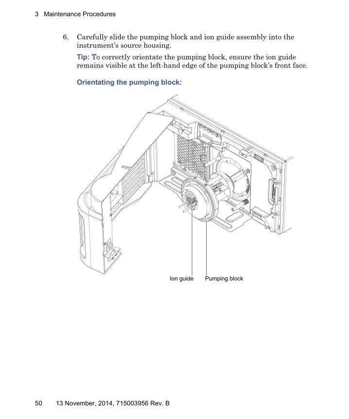
6. Carefully slide the pumping block and ion guide assembly into the instrument’s source housing.
Tip: To correctly orientate the pumping block, ensure the ion guide remains visible at the left-hand edge of the pumping block’s front face.
Orientating the pumping block:
Pumping blockIon guide
50 13 November, 2014, 715003956 Rev. B

Cleaning the ion guide assembly
7. Secure the pumping block to the instrument using the 4 pumping block securing screws, and tighten them using the 3-mm Allen wrench.
Securing the pumping block:
8. Fit the ion block and source components to the instrument (see page 38).
9. Fit the source enclosure to the instrument (see page 30).
13 November, 2014, 715003956 Rev. B 51

3 Maintenance Procedures
Emptying the nitrogen exhaust trap
Inspect the nitrogen exhaust trap in the instrument’s exhaust line daily, and empty it before it is more than 10% full.
Nitrogen exhaust trap:
Required material
Chemical-resistant, powder-free gloves
To empty the trap:
1. In the software, stop the LC flow.
2. Remove the source enclosure (see page 29).
TP03404
From instrument exhaust connection (12-mm OD)
To laboratory exhaust port (12-mm OD)
Exhaust solenoid cable
52 13 November, 2014, 715003956 Rev. B

Emptying the nitrogen exhaust trap
3. Unscrew and remove the nitrogen exhaust trap from its cap and associated fittings.
4. Dispose of the waste liquid in accordance with local environmental regulations.
5. Fit and fully tighten the trap onto its cap.
6. Secure the trap in the upright position.
7. Refit the source enclosure (see page 30).
8. In the software, start the LC flow.
Warning: To avoid personal contamination with biohazards or toxic materials that may be present in the exhaust trap bottle’s waste liquid, always wear chemical-resistant, pow-der-free gloves while handling the nitrogen exhaust trap.
Warning: The waste liquid can be contaminated with biohaz-ards or toxic materials. Dispose of it according to local envi-ronmental regulations.
13 November, 2014, 715003956 Rev. B 53
3 Maintenance Procedures
Replacing the roughing pump’s oil
Note: This section applies to the Performance QDa Detector only. The Standard instrument uses a diagphragm pump, which does not require oil.
Replace the roughing pump’s oil when any of these conditions apply:
• The oil level is low.
Tip: To check the oil level, view it through the sight glass on the pump’s rear panel.
• The oil in the pump appears darker than new oil, emits a strange odor, or is visibly contaminated.
• The oil has been in use for more than two years.
Note: If you are using a diaphragm pump, attached to the instrument’s rear panel, this procedure is not necessary. The diaphragm pump does not use oil.
Required materials:
• Chemical-resistant, powder-free gloves
• Tray on which to place the pump
• Container to catch used oil
• Suitable pump oil
To add oil to the roughing pump:
1. Power-off the instrument using the power button in the top, left-hand corner of the front panel.
2. Wait for approximately 5 minutes to allow the instrument to vent.
3. Switch off the pump, and disconnect the power cable.
4. Place the pump on a tray suitable for catching dripping oil.
Warning: To avoid personal contamination with biohazards or toxic materials in used pump oil, always wear chemical-resistant, powder-free gloves while performing this procedure.
Warning: To avoid burn injuries, allow the pump to cool before touching surfaces displaying the burn warning symbol.
54 13 November, 2014, 715003956 Rev. B

Replacing the roughing pump’s oil
5. Remove the oil-drain plug from the pump’s rear panel.
Roughing-pump rear panel:
6. Tilt the pump slightly, and catch the oil in a suitable container.
7. Dispose of the oil according to local environmental regulations.
8. Insert the oil-drain plug into the pump’s rear panel.
9. To flush the pump, pour 50 mL of fresh oil into the pump inlet, on pump’s top side.
Tip: If you encounter difficulty, remove the separator.
10. Operate the pump briefly.
11. Drain the flushing oil into a suitable container.
12. If necessary, repeat steps 9 through 11 until all contaminants are removed.
Oil level sight glass
Oil drain plug
13 November, 2014, 715003956 Rev. B 55
3 Maintenance Procedures
13. Remove the oil-inlet plug, and pour fresh oil into the oil-inlet port until the level reaches the sight glass’s ‘max’ mark.
14. Insert the oil-drain plug into the pump’s rear panel.
Notice: Do not overfill the pump. That is, do not fill it beyond the “max” mark.
56 13 November, 2014, 715003956 Rev. B

A Safety Advisories
Waters instruments and devices display hazard symbols that alert you to the hidden dangers associated with a product’s operation and maintenance. The symbols also appear in product manuals where they accompany statements describing the hazards and advising how to avoid them. This appendix presents the safety symbols and statements that apply to all of the products that Waters offers.
Contents:
Topic Page
Warning symbols.............................................................................. 58
Notices .............................................................................................. 61
Warnings that apply to all Waters instruments and devices ........ 62
Electrical and handling symbols ..................................................... 69
13 November, 2014, 715003956 Rev. B 57

A Safety Advisories
Warning symbols
Warning symbols alert you to the of death, injury or seriously adverse physiological reactions associated with an instrument’s use or misuse. Heed all warnings when you install, repair, or operate any Waters instrument or device. Waters accepts no liability in cases of injury or property damage resulting from the failure of individuals to comply with any safety precaution when installing, repairing, or operating any of its instruments or devices.
The following symbols warn of s that can arise when you operate or maintain a Waters instrument or device, or a component of an instrument or device. When one of these symbols appear in a manual’s narrative sections or procedures, an accompanying statement identifies the applicable and explains how to avoid it.
Warning: (General risk of danger. When this symbol appears on an instrument, consult the instrument’s user documentation for important safety-related information before you use the instrument.)
Warning: (Risk of burn injury from contacting hot surfaces.)
Warning: (Risk of electric shock.)
Warning: (Risk of fire.)
Warning: (Risk of sharp-point puncture injury.)
Warning: (Risk of hand crush injury.)
Warning: (Risk of exposure to ultraviolet radiation.)
Warning: (Risk of contacting corrosive substances.)
Warning: (Risk of exposure to a toxic substance.)
Warning: (Risk of personal exposure to laser radiation.)
Warning: (Risk of exposure to biological agents that can pose a serious health threat.)
58 13 November, 2014, 715003956 Rev. B

Warning symbols
Specific warnings
The following warnings (both symbols and text) can appear in the user manuals of particular instruments and devices and on labels affixed to them or their component parts.
Burst warning
This warning applies to Waters instruments and devices fitted with nonmetallic tubing.
Mass spectrometer shock hazard
The following warning applies to all Waters mass spectrometers.
Warning: (Risk of tipping.)
Warning: (Risk of explosion.)
Warning: (Risk of eye injury.)
Warning: To avoid injury from bursting, nonmetallic tubing, heed these precautions when working in the vicinity of such tubing when it is pressurized:• Wear eye protection.• Extinguish all nearby flames.• Do not use tubing that is, or has been, stressed or kinked.• Do not expose nonmetallic tubing to incompatible compounds like
tetrahydrofuran (THF) and nitric or sulfuric acids.• Be aware that some compounds, like methylene chloride and
dimethyl sulfoxide, can cause nonmetallic tubing to swell, significantly reducing the pressure at which the tubing can rupture.
Warning: To avoid electric shock, do not remove the mass spectrometer’s protective panels. The components they cover are not user-serviceable.
13 November, 2014, 715003956 Rev. B 59

A Safety Advisories
The following warning applies to certain mass spectrometers when they are in Operate mode.
Mass spectrometer flammable solvents warning
This warning applies to mass spectrometers performing an analysis that requires the use of flammable solvents.
Biohazard warning
The following warning applies to Waters instruments and devices that can process material containing biohazards, which are substances that contain biological agents capable of producing harmful effects in humans.
Warning: To avoid nonlethal electric shock, ensure the mass spectrometer is in Standby mode before you touch any of its external surfaces that are marked with this high voltage warning symbol.
Warning: To prevent ignition of flammable solvent vapors in the enclosed space of a mass spectrometer’s ion source, ensure that nitrogen flows continuously through the source. The nitrogen supply pressure must not fall below 600 kPa (6.0 bar, 87 psi) during an analysis requiring the use of flammable solvents.
Warning: To avoid infection with potentially infectious, human-sourced products, inactivated microorganisms, and other biological materials, assume that all biological fluids that you handle are infectious. Specific precautions appear in the latest edition of the US National Institutes of Health (NIH) publication, Biosafety in Microbiological and Biomedical Laboratories (BMBL).Observe Good Laboratory Practice (GLP) at all times, particularly when working with hazardous materials, and consult your the biohazard safety representative for your organization regarding the proper use and handling of infectious substances.
60 13 November, 2014, 715003956 Rev. B

Notices
Biohazard and chemical hazard warning
This warning applies to Waters instruments and devices that can process biohazards, corrosive materials, or toxic materials.
Notices
Notices appear where an instrument or device can be subject to use or misuse that can damage it or compromise a sample’s integrity. The exclamation point symbol and its associated statement alert you to such risk.
Warning: To avoid personal contamination with biohazards, toxic materials, or corrosive materials, you must understand the hazards associated with their handling. Guidelines prescribing the proper use and handling of such materials appear in the latest edition of the National Research Council's publication, Prudent Practices in the Laboratory: Handling and Disposal of Chemicals. Observe Good Laboratory Practice (GLP) at all times, particularly when working with hazardous materials, and consult the safety representative for your organization regarding its protocols for handling such materials.
Notice: To avoid damaging the instrument’s case, do not clean it with abrasives or solvents.
13 November, 2014, 715003956 Rev. B 61

A Safety Advisories
Warnings that apply to all Waters instruments and devices
When operating this device, follow standard quality-control procedures and the equipment guidelines in this section.
Attention: Changes or modifications to this unit not expressly approved by the party responsible for compliance could void the user’s authority to operate the equipment.
Important: Toute modification sur cette unité n’ayant pas été expressément approuvée par l’autorité responsable de la conformité à la réglementation peut annuler le droit de l’utilisateur à exploiter l’équipement.
Achtung: Jedwede Änderungen oder Modifikationen an dem Gerät ohne die ausdrückliche Genehmigung der für die ordnungsgemäße Funktionstüchtigkeit verantwortlichen Personen kann zum Entzug der Bedienungsbefugnis des Systems führen.
Avvertenza: qualsiasi modifica o alterazione apportata a questa unità e non espressamente autorizzata dai responsabili per la conformità fa decadere il diritto all'utilizzo dell'apparecchiatura da parte dell'utente.
Atencion: cualquier cambio o modificación efectuado en esta unidad que no haya sido expresamente aprobado por la parte responsable del cumplimiento puede anular la autorización del usuario para utilizar el equipo.
注意:未經有關法規認證部門允許對本設備進行的改變或修改,可能會使使用者喪失操作該設
備的權利。
注意:未经有关法规认证部门明确允许对本设备进行的改变或改装,可能会使使用者丧失操作该设备的合法性。
주의: 규정 준수를 책임지는 당사자의 명백한 승인 없이 이 장치를 개조 또는 변경할 경우, 이 장치를 운용할 수 있는 사용자 권한의 효력을 상실할 수 있습니다.
注意:規制機関から明確な承認を受けずに本装置の変更や改造を行うと、本装置のユーザーとしての承認が無効になる可能性があります。
62 13 November, 2014, 715003956 Rev. B

Warnings that apply to all Waters instruments and devices
Warning: Use caution when working with any polymer tubing under pressure:• Always wear eye protection when near pressurized polymer tubing.• Extinguish all nearby flames.• Do not use tubing that has been severely stressed or kinked.• Do not use nonmetallic tubing with tetrahydrofuran (THF) or concentrated
nitric or sulfuric acids.• Be aware that methylene chloride and dimethyl sulfoxide cause nonmetallic
tubing to swell, which greatly reduces the rupture pressure of the tubing.Attention: Manipulez les tubes en polymère sous pression avec precaution:• Portez systématiquement des lunettes de protection lorsque vous vous
trouvez à proximité de tubes en polymère pressurisés.• Eteignez toute flamme se trouvant à proximité de l’instrument.• Evitez d'utiliser des tubes sévèrement déformés ou endommagés.• Evitez d'utiliser des tubes non métalliques avec du tétrahydrofurane (THF)
ou de l'acide sulfurique ou nitrique concentré.• Sachez que le chlorure de méthylène et le diméthylesulfoxyde entraînent le
gonflement des tuyaux non métalliques, ce qui réduit considérablement leur pression de rupture.
Vorsicht: Bei der Arbeit mit Polymerschläuchen unter Druck ist besondere Vorsicht angebracht:• In der Nähe von unter Druck stehenden Polymerschläuchen stets
Schutzbrille tragen.• Alle offenen Flammen in der Nähe löschen.• Keine Schläuche verwenden, die stark geknickt oder überbeansprucht sind.• Nichtmetallische Schläuche nicht für Tetrahydrofuran (THF) oder
konzentrierte Salpeter- oder Schwefelsäure verwenden.• Durch Methylenchlorid und Dimethylsulfoxid können nichtmetallische
Schläuche quellen; dadurch wird der Berstdruck des Schlauches erheblich reduziert.
13 November, 2014, 715003956 Rev. B 63

A Safety Advisories
Attenzione: fare attenzione quando si utilizzano tubi in materiale polimerico sotto pressione:• Indossare sempre occhiali da lavoro protettivi nei pressi di tubi di polimero
pressurizzati.• Spegnere tutte le fiamme vive nell'ambiente circostante.• Non utilizzare tubi eccessivamente logorati o piegati.• Non utilizzare tubi non metallici con tetraidrofurano (THF) o acido solforico
o nitrico concentrati.• Tenere presente che il cloruro di metilene e il dimetilsolfossido provocano
rigonfiamenti nei tubi non metallici, riducendo notevolmente la pressione di rottura dei tubi stessi.
Advertencia: se recomienda precaución cuando se trabaje con tubos de polímero sometidos a presión:• El usuario deberá protegerse siempre los ojos cuando trabaje cerca de tubos
de polímero sometidos a presión.• Si hubiera alguna llama las proximidades.• No se debe trabajar con tubos que se hayan doblado o sometido a altas
presiones.• Es necesario utilizar tubos de metal cuando se trabaje con tetrahidrofurano
(THF) o ácidos nítrico o sulfúrico concentrados.• Hay que tener en cuenta que el cloruro de metileno y el sulfóxido de dimetilo
dilatan los tubos no metálicos, lo que reduce la presión de ruptura de los tubos.
警告:當在有壓力的情況下使用聚合物管線時,小心注意以下幾點。
• 當接近有壓力的聚合物管線時一定要戴防護眼鏡。
• 熄滅附近所有的火焰。
• 不要使用已經被壓癟或嚴重彎曲管線。
• 不要在非金屬管線中使用四氫呋喃或濃硝酸或濃硫酸。
• 要了解使用二氯甲烷及二甲基亞楓會導致非金屬管線膨脹,大大降低管線的耐壓能力。
64 13 November, 2014, 715003956 Rev. B

Warnings that apply to all Waters instruments and devices
警告:当有压力的情况下使用管线时,小心注意以下几点:
• 当接近有压力的聚合物管线时一定要戴防护眼镜。
• 熄灭附近所有的火焰。
• 不要使用已经被压瘪或严重弯曲的管线。
• 不要在非金属管线中使用四氢呋喃或浓硝酸或浓硫酸。
• 要了解使用二氯甲烷及二甲基亚枫会导致非金属管线膨胀,大大降低管线的耐压能力。
경고: 가압 폴리머 튜브로 작업할 경우에는 주의하십시오.• 가압 폴리머 튜브 근처에서는 항상 보호 안경을 착용하십시오.• 근처의 화기를 모두 끄십시오.• 심하게 변형되거나 꼬인 튜브는 사용하지 마십시오.• 비금속(Nonmetallic) 튜브를 테트라히드로푸란(Tetrahydrofuran: THF) 또는 농축 질산 또는 황산과 함께 사용하지 마십시오.
• 염화 메틸렌(Methylene chloride) 및 디메틸술폭시드(Dimethyl sulfoxide)는 비금속 튜브를 부풀려 튜브의 파열 압력을 크게 감소시킬 수 있으므로 유의하십시오.
警告:圧力のかかったポリマーチューブを扱うときは、注意してください。
• 加圧されたポリマーチューブの付近では、必ず保護メガネを着用してください。
• 近くにある火を消してください。
• 著しく変形した、または折れ曲がったチューブは使用しないでください。
• 非金属チューブには、テトラヒドロフラン(THF)や高濃度の硝酸または硫酸などを流
さないでください。
• 塩化メチレンやジメチルスルホキシドは、非金属チューブの膨張を引き起こす場合があり、その場合、チューブは極めて低い圧力で破裂します。
13 November, 2014, 715003956 Rev. B 65
A Safety Advisories
Warning: The user shall be made aware that if the equipment is used in a manner not specified by the manufacturer, the protection provided by the equipment may be impaired.
Attention: L’utilisateur doit être informé que si le matériel est utilisé d’une façon non spécifiée par le fabricant, la protection assurée par le matériel risque d’être défectueuses.
Vorsicht: Der Benutzer wird darauf aufmerksam gemacht, dass bei unsachgemäßer Verwenddung des Gerätes die eingebauten Sicherheitseinrichtungen unter Umständen nicht ordnungsgemäß funktionieren.
Attenzione: si rende noto all'utente che l'eventuale utilizzo dell'apparecchiatura secondo modalità non previste dal produttore può compromettere la protezione offerta dall'apparecchiatura.
Advertencia: el usuario deberá saber que si el equipo se utiliza de forma distinta a la especificada por el fabricante, las medidas de protección del equipo podrían ser insuficientes.
警告:使用者必須非常清楚如果設備不是按照製造廠商指定的方式使用,那麼該設備所提供的保護將被消弱。
警告:使用者必须非常清楚如果设备不是按照制造厂商指定的方式使用,那么该设备所提供的保护将被削弱。
경고: 제조업체가 명시하지 않은 방식으로 장비를 사용할 경우 장비가 제공하는 보호 수단이 제대로 작동하지 않을 수 있다는 점을 사용자에게 반드시 인식시켜야 합니다.
警告: ユーザーは、製造元により指定されていない方法で機器を使用すると、機器が提供している保証が無効になる可能性があることに注意して下さい。
66 13 November, 2014, 715003956 Rev. B

Warnings that address the replacing of fuses
Warnings that address the replacing of fuses
The following warnings pertain to instruments equipped with user-replaceable fuses.
If the fuse types and ratings appear on the instrument:
Warning: To protect against fire, replace fuses with those of the type and rating printed on panels adjacent to instrument fuse covers.Attention: pour éviter tout risque d'incendie, remplacez toujours les fusibles par d'autres du type et de la puissance indiqués sur le panneau à proximité du couvercle de la boite à fusible de l'instrument.Vorsicht: Zum Schutz gegen Feuer die Sicherungen nur mit Sicherungen ersetzen, deren Typ und Nennwert auf den Tafeln neben den Sicherungsabdeckungen des Geräts gedruckt sind.Attenzione: per garantire protezione contro gli incendi, sostituire i fusibili con altri dello stesso tipo aventi le caratteristiche indicate sui pannelli adiacenti alla copertura fusibili dello strumento.Advertencia: Para evitar incendios, sustituir los fusibles por aquellos del tipo y características impresos en los paneles adyacentes a las cubiertas de los fusibles del instrumento.
警告 :為了避免火災,更換保險絲時,請使用與儀器保險絲蓋旁面板上所印刷之相同類型與規格的保險絲。
警告:为了避免火灾,应更换与仪器保险丝盖旁边面板上印刷的类型和规格相同的保险丝。
경고: 화재의 위험을 막으려면 기기 퓨즈 커버에 가까운 패널에 인쇄된 것과 동일한 타입 및 정격의 제품으로 퓨즈를 교체하십시오.
警告:火災予防のために、ヒューズ交換では機器ヒューズカバー脇のパネルに記載されているタイプおよび定格のヒューズをご使用ください。
13 November, 2014, 715003956 Rev. B 67
A Safety Advisories
If the fuse types and ratings do not appear on the instrument:
Warning: To protect against fire, replace fuses with those of the type and rating indicated in the “Replacing fuses” section of the Maintenance Procedures chapter.Attention: pour éviter tout risque d'incendie, remplacez toujours les fusibles par d'autres du type et de la puissance indiqués dans la rubrique "Remplacement des fusibles" du chapitre traitant des procédures de maintenance.Vorsicht: Zum Schutz gegen Feuer die Sicherungen nur mit Sicherungen ersetzen, deren Typ und Nennwert im Abschnitt "Sicherungen ersetzen" des Kapitels "Wartungsverfahren" angegeben sind.Attenzione: per garantire protezione contro gli incendi, sostituire i fusibili con altri dello stesso tipo aventi le caratteristiche indicate nel paragrafo "Sostituzione dei fusibili" del capitolo "Procedure di manutenzione".Advertencia: Para evitar incendios, sustituir los fusibles por aquellos del tipo y características indicados en la sección "Sustituir fusibles".
警告 :為了避免火災,更換保險絲時,應使用「維護步驟」章節中「更換保險絲」所指定之相同類型與規格的保險絲。
警告:为了避免火灾,应更换 “维护步骤 ”一章的 “更换保险丝 ”一节中介绍的相同类型和规格的保险丝。
경고: 화재의 위험을 막으려면 유지관리 절차 단원의 “퓨즈 교체” 절에 설명된 것과 동일한 타입 및 정격의 제품으로 퓨즈를 교체하십시오.
警告: 火災予防のために、ヒューズ交換ではメンテナンス項目の「ヒューズの交換」に記載されているタイプおよび定格のヒューズをご使用ください。
68 13 November, 2014, 715003956 Rev. B

Electrical and handling symbols
Electrical and handling symbols
Electrical symbols
The following electrical symbols and their associated statements can appear in instrument manuals and on an instrument’s front or rear panels.
Electrical power on
Electrical power off
Standby
Direct current
Alternating current
Protective conductor terminal
Frame, or chassis, terminal
Fuse
13 November, 2014, 715003956 Rev. B 69

A Safety Advisories
Handling symbols
The following handling symbols and their associated statements can appear on labels affixed to the packaging in which instruments, devices, and component parts are shipped.
Keep upright!
Keep dry!
Fragile!
Use no hooks!
70 13 November, 2014, 715003956 Rev. B

B Specifications
The applicability of the following specifications depends on the conditions in individual laboratories. Refer to the ACQUITY QDa Detector System Site Preparation Guide, or contact the Waters® Technical Service organization for additional information about the specifications.
Contents:
Topic Page
Physical specifications ..................................................................... 72
Environmental specifications .......................................................... 72
Electrical specifications ................................................................... 73
13 November, 2014, 715003956 Rev. B 71

B Specifications
Physical specifications
The following table lists the physical specifications for the ACQUITY QDa Detector.
Environmental specifications
The following table lists the environmental specifications for the ACQUITY QDa Detector.
Physical specifications:
Attribute Specification
Height 20.0 cm
Width 35.3 cm
Depth Standard instrument: 75.0 cmPerformance instrument: 65.0 cm
Weight Standard instrument: 28 kgPerformance instrument: 25 kg
Environmental specifications:
Attribute Specification
Operating temperature (performance is specified)
15 °C to 28 °C
Safe operating temperature (no damage or hazard)
4 °C to 40 °C
Operating humidity 20% to 80%, non-condensing
72 13 November, 2014, 715003956 Rev. B

Electrical specifications
Electrical specifications
The following table lists the electrical specifications for the ACQUITY QDa Detector.
Electrical specifications:
Attribute Specification
Protection classa
a. Protection Class I – The insulating scheme used in the instrument to protect from electrical shock. Class I identifies a single level of insulation between live parts (wires) and exposed conductive parts (metal panels), in which the exposed conductive parts are connected to a grounding system. In turn, this grounding system is connected to the third pin (ground pin) on the electrical power cord plug.
Class 1
Overvoltage categoryb
b. Overvoltage Category II – Pertains to instruments that receive their electrical power from a local level such as an electrical wall outlet.
II
Pollution degreec
c. Pollution Degree 2 – A measure of pollution on electrical circuits that can produce a reduction of dielectric strength or surface resistivity. Degree 2 refers only to normally nonconductive pollution. Occasionally, however, expect a temporary conductivity caused by condensation.
2
Moisture protectiond
d. Moisture Protection – Normal (IPX0) – IPX0 means that no Ingress Protection against any type of dripping or sprayed water exists. The “X” is a placeholder that identifies protection against dust, if applicable.
IPX0
Line voltages, nominal 100 V to 240 V
Frequency 50/60 Hz
Maximum power draw 400 W
13 November, 2014, 715003956 Rev. B 73

B Specifications
Input/output specifications
The following table lists the input and output specifications for the ACQUITY QDa Detector.
Input and output specifications:
Attribute Specification
USB Ports Maximum voltage: 5 VMaximum current: 1 ATransmission Rate: 480 Mbits/s
Com Port (RS232) Baud rate 96008 bits, no parity, 1 stop bit (8-N-1)
Contact Closure Outputs (Stop Flow/Switch)
Maximum voltage: 30 VMaximum current: 0.5 AMaximum VA Rating: 3 W
Event Inputs (Inject Start/Event In)
Voltage threshold: 2.5 VMaximum input voltage: 100 VMinimum input voltage: -100 VMaximum current: 1.12 mA
Analogue Out Maximum output: +10 VMinimum output: -10 VOutput current: 10 mA
74 13 November, 2014, 715003956 Rev. B

C Materials of Construction and Compatible Solvents
Warning: To confirm the integrity of the source exhaust system, you must address any safety issues raised by the contents of this appendix.
Contents:
Topic Page
Preventing contamination ............................................................... 76
Items exposed to solvent.................................................................. 76
Solvents used to prepare mobile phases ......................................... 77
13 November, 2014, 715003956 Rev. B 75

C Materials of Construction and Compatible Solvents
Preventing contamination
For information about preventing contamination, refer to Controlling Contamination in Ultra Performance LC/MS and HPLC/MS Systems (part number 715001307), which you can download from the Waters Web site (www.waters.com).
Items exposed to solvent
The items that appear in the following table can be exposed to solvent. You must evaluate the safety issues if the solvents used in your application differ from the solvents normally used with these items. See page 77 for details about the most common ingredients used to prepare mobile phases.
Items exposed to solvent:
Item Material
Gas exhaust port Aluminium
Gas tubes FEP (fluorinated ethylene propylene)
Ion block Stainless steel
Ion block support PEEK® (polyetheretherketone)
O-rings Viton® orPTFE (polytetrafluoroethylene)-encapsulated Viton
Solvent waste/leak management Tygon tubing
Source enclosure Alochromed aluminium
Waste bottle Polypropylene
Waste bottle push-in fittings NBR (nitrile butadiene rubber), SST (Stainless steel), PBT (polybutylene Terephthalate), and POM (polyoxymethylene)
76 13 November, 2014, 715003956 Rev. B

Solvents used to prepare mobile phases
Solvents used to prepare mobile phases
The following solvents, frequently used to prepare mobile phases for reverse-phase LC/MS (API), are not expected to adversely affect the performance of the materials shown in the preceding table:
Water 100%
Methanol 100%
Acetonitrile 100%
Formic acid <0.1%
Acetic acid <0.1%
Trifluoroacetic acid (TFA) <0.1%
Ammonium acetate <10mM
Ammonium formate <10mM
2-Propanol (IPA) 100%
Ammonium hydroxide <0.18%
Triethyl amine (TEA) <0.1%
13 November, 2014, 715003956 Rev. B 77

C Materials of Construction and Compatible Solvents
78 13 November, 2014, 715003956 Rev. B

D External Connections
This appendix describes the instrument’s external connections.
Warning: To avoid injury, always perform a risk assessment when manually handling the QDa Detector. Waters recommend two people lift the instrument.
Notice: If you must remove the instrument from service, contact Waters Technical Service for recommended cleaning, flushing, and packaging procedures.See page iv.
Contents:
Topic Page
External wiring and vacuum connections....................................... 80
Connecting the Standard instrument’s backing pump.................. 81
Connecting the Performance instrument’s backing pump............. 82
Connecting to the nitrogen gas supply............................................ 86
Connecting the nitrogen exhaust line............................................. 87
Connecting the workstation............................................................. 90
Connecting Ethernet cables............................................................. 91
Input/output signal connectors........................................................ 92
Connecting to the power supply...................................................... 95
13 November, 2014, 715003956 Rev. B 79

D External Connections
External wiring and vacuum connections
When making connections to the QDa detector’s rear panel, refer to the following diagram.
Rear panel connections:
For details of supported system configurations, contact Waters Technical Service.
Ethernet cable Vacuum pump tubing
Waste bottle solenoid connection
Power cable Diaphragm pump supports
Nitrogen inlet
Backing pump connector
Diaphragm pump securing screw Diaphragm pump
securing screw
Service port
80 13 November, 2014, 715003956 Rev. B

Connecting the Standard instrument’s backing pump
Connecting the Standard instrument’s backing pump
The Standard instrument uses a diaphragm pump attached to the back of the instrument.
Note: To connect the Performance instrument’s backing pump, see page 81.
Required materials:
• Chemical-resistant, powder-free gloves
• Phillips® (cross-head) screwdriver
• Diaphragm vacuum hose (included in the installation kit)
To connect the diaphragm pump:
1. Hook the pump on to the 3 diaphragm pump supports on the rear of the instrument, shown in the figure on page 80.
2. Secure the pump to the instrument using the 2 screws, and tighten them using the Phillips (cross-head) screwdriver.
3. Connect the length of diaphragm pump vacuum hose in step 2 to the 1-inch OD straight vacuum port on the instrument’s rear panel.
4. Route the open end of the exhaust tubing to a suitable exhaust vent.
5. Connect the diaphragm pump cable to the backing pump connector on the instrument’s rear panel (see page 80).
Requirement: When using the diaphragm pump, ensure that the 0.1-mm entrance-aperture disc is installed.
Warning: To avoid personal contamination with biohazards or toxic materials in used pump oil, always wear chemical-resistant, powder-free gloves while performing this procedure.
Notice: The instrument requires two separate exhaust systems: one for nitrogen, the other for the roughing pump. Vent them to atmosphere through separate exhaust lines. Oil mist can severely damage the instrument if the nitrogen exhaust line connects with the roughing pump exhaust line. Your warranty does not cover damage caused by routing exhaust lines incorrectly.
13 November, 2014, 715003956 Rev. B 81

D External Connections
Connecting the Performance instrument’s backing pump
Note: To connect the Standard instrument’s backing pump, see page 81.
Required materials:
• Chemical-resistant, powder-free gloves
• 7-mm nut driver
• 8-mm Allen wrench
• Sharp knife
• NW16 clamp (included in the installation kit)
• NW16 O-ring (included in the installation kit)
• PVC exhaust tubing (included in the installation kit)
• PVC hose clamps (included in the installation kit)
• 1-inch ID vacuum hose (included in the installation kit)
Exhaust port
Vacuum hose assembly
Power cable
82 13 November, 2014, 715003956 Rev. B

Connecting the Performance instrument’s backing pump
To connect the roughing pump:
1. Place a suitable PTFE drip tray on the floor, within 5 feet of the instrument.
Requirement: The pump must be oriented in a way that allows easy daily access to the gas ballast valve and oil-level sight glass.
2. Place the pump on the PTFE drip tray.
3. Using the NW16 center ring and clamp, and the 7-mm nut driver, attach the flanged end of a length of 1-inch ID vacuum hose to the vacuum port on the pump.
Warning: The pump and its connections can be contaminated with biohazardous and/or toxic materials. Always wear chemical-resistant, powder-free gloves when performing this procedure.
Notice:
• To ensure correct operation of the roughing pump, the pump must be installed within 1 degree of horizontal.
• The area where the roughing pump is located must have an ambient temperature of 15 to 40 ºC (59 to 104 ºF).
• To ensure proper ventilation, the pump must be installed with the following minimum clearances:
Right-side minimum clearance is 15.24 cm (6 inches)
Back-side minimum clearance is 15.24 cm (6 inches)
Front-side minimum clearance is 35.56 cm (14 inches)
Left-side minimum clearance is 15.24 cm (6 inches)
13 November, 2014, 715003956 Rev. B 83

D External Connections
4. Using a hose clamp, connect the opposite end of the length of 1-inch vacuum hose in step 3 to the 1-inch OD straight vacuum port on the instrument’s rear panel.
5. Using a hose clamp, connect a length of 19-mm clear PVC exhaust tubing to the pump exhaust port.
6. Route the open end of the exhaust tubing to a suitable exhaust vent.
7. Check the oil level in the pump (see “Replacing the roughing pump’s oil” on page 54.
8. Make the electrical connections to the rotary pump (see page 85).
Notice: To avoid gas leaks, use the sharp knife to cut the PVC exhaust tubing squarely (that is, perpendicular to its horizontal axis).
Notice: The instrument requires two separate exhaust systems: one for nitrogen, the other for the roughing pump. Vent them to atmosphere through separate exhaust lines. Oil mist can severely damage the instrument if the nitrogen exhaust line connects with the roughing pump exhaust line. Your warranty does not cover damage caused by routing exhaust lines incorrectly.
Notice: To ensure correct operation of the roughing pump, do not operate the pump with the oil level at less than 30% of the MAX level.
84 13 November, 2014, 715003956 Rev. B
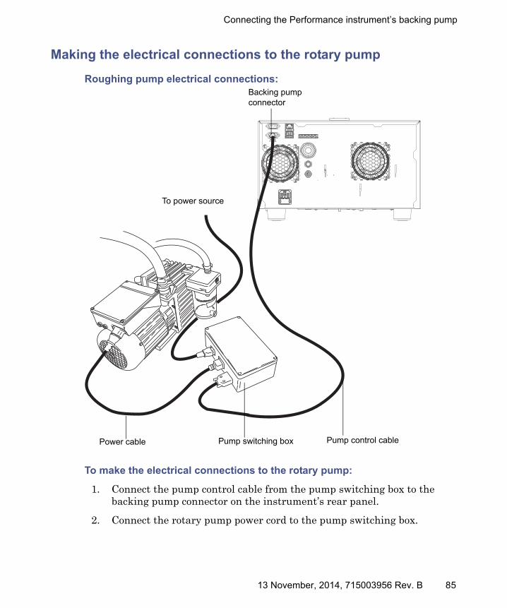
Connecting the Performance instrument’s backing pump
Making the electrical connections to the rotary pump
Roughing pump electrical connections:
To make the electrical connections to the rotary pump:
1. Connect the pump control cable from the pump switching box to the backing pump connector on the instrument’s rear panel.
2. Connect the rotary pump power cord to the pump switching box.
Pump switching boxPower cable
To power source
Backing pump connector
Pump control cable
13 November, 2014, 715003956 Rev. B 85

D External Connections
3. Connect the pump switching box power cord to the main power source, and use the power switch on the pump to power it on.
Tip: The relay box allows the instrument to remotely control the backing pump.
Connecting to the nitrogen gas supply
Required materials
• Chemical-resistant, powder-free gloves
• Sharp knife
• Wrench
• 6-mm PTFE tubing (included in the installation kit)
• 6-mm stud
• Nitrogen regulator
To connect the nitrogen gas supply:
1. Use the sharp knife to cut a length of 6-mm PTFE tubing long enough to connect the rear of the instrument to the nitrogen regulator.
2. Connect one end of the 6-mm PTFE tubing to the nitrogen inlet port on the rear of the instrument (see page 80).
3. Attach the nitrogen regulator to the nitrogen supply.
4. Install the 6-mm stud into the regulator outlet.
Notice: To avoid gas leaks, use the sharp knife to cut the PTFE tubing squarely (that is, perpendicular to its horizontal axis).
86 13 November, 2014, 715003956 Rev. B

Connecting the nitrogen exhaust line
5. Connect the free end of the long piece of 6-mm PTFE tubing to the 6-mm stud.
Requirement: The nitrogen must be dry and oil-free, with a purity of at least 95%. Regulate the supply at 600 to 690 kPa (6.0 to 6.9 bar, 87 to 100 psi).
Connecting the nitrogen exhaust line
Required materials
• Chemical-resistant, powder-free gloves
• Sharp knife
• 12-mm PTFE tubing (included in the Waters Rough Pump Connect Kit)
• 12-mm right-angle elbow connectors (included in the Waters Start-Up Kit)
13 November, 2014, 715003956 Rev. B 87
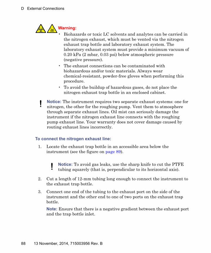
D External Connections
To connect the nitrogen exhaust line:
1. Locate the exhaust trap bottle in an accessible area below the instrument (see the figure on page 89).
2. Cut a length of 12-mm tubing long enough to connect the instrument to the exhaust trap bottle.
3. Connect one end of the tubing to the exhaust port on the side of the instrument and the other end to one of two ports on the exhaust trap bottle.
Note: Ensure that there is a negative gradient between the exhaust port and the trap bottle inlet.
Warning:
• Biohazards or toxic LC solvents and analytes can be carried in the nitrogen exhaust, which must be vented via the nitrogen exhaust trap bottle and laboratory exhaust system. The laboratory exhaust system must provide a minimum vacuum of 0.20 kPa (2 mbar, 0.03 psi) below atmospheric pressure (negative pressure).
• The exhaust connections can be contaminated with biohazardous and/or toxic materials. Always wear chemical-resistant, powder-free gloves when performing this procedure.
• To avoid the buildup of hazardous gases, do not place the nitrogen exhaust trap bottle in an enclosed cabinet.
Notice: The instrument requires two separate exhaust systems: one for nitrogen, the other for the roughing pump. Vent them to atmosphere through separate exhaust lines. Oil mist can seriously damage the instrument if the nitrogen exhaust line connects with the roughing pump exhaust line. Your warranty does not cover damage caused by routing exhaust lines incorrectly.
Notice: To avoid gas leaks, use the sharp knife to cut the PTFE tubing squarely (that is, perpendicular to its horizontal axis).
88 13 November, 2014, 715003956 Rev. B
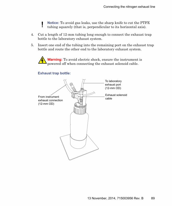
Connecting the nitrogen exhaust line
4. Cut a length of 12-mm tubing long enough to connect the exhaust trap bottle to the laboratory exhaust system.
5. Insert one end of the tubing into the remaining port on the exhaust trap bottle and route the other end to the laboratory exhaust system.
Exhaust trap bottle:
Notice: To avoid gas leaks, use the sharp knife to cut the PTFE tubing squarely (that is, perpendicular to its horizontal axis).
Warning: To avoid electric shock, ensure the instrument is powered off when connecting the exhaust solenoid cable.
TP03404
From instrument exhaust connection (12-mm OD)
To laboratory exhaust port (12-mm OD)
Exhaust solenoid cable
13 November, 2014, 715003956 Rev. B 89

D External Connections
Connecting the exhaust solenoid cable
To connect the exhaust solenoid cable:
1. Connect the exhaust solenoid cable to the port on the exhaust trap bottle (see page 89).
2. Connect the other end of the cable to the exhaust solenoid connection on the rear panel of the instrument (see page 80).
Connecting the workstation
Before connecting the workstation to the instrument, set up the workstation according to its accompanying instructions. Locate the workstation within 5 meters (16 feet) of the instrument.
Requirement: Use shielded network cables with the instrument to ensure compliance with FCC, and other, limits.
To connect the workstation:
1. Connect the peripherals to the PC.
2. Connect one end of the shielded network cable to the ethernet port on the rear panel of the instrument.
3. Connect the other end of the ethernet cable to the ACQUITY ethernet switch box.
4. Connect one end of another ethernet cable to the ACQUITY ethernet switch box.
5. Connect the other end of the shielded network cable to the port labeled Instrument LAN on the workstation rear panel.
Warning: To avoid injury from electric shock or fire, and to prevent damage to the workstation and ancillary equipment, do not place objects filled with liquid—such as solvent bottles—on these items, or expose them to dripping or splashing liquids.
90 13 November, 2014, 715003956 Rev. B

Connecting Ethernet cables
To connect the instrument to the power source:
1. Select the correct power cord for your location.
2. Connect the female end of the power cord to the power port on the rear panel of the instrument.
Connecting Ethernet cables
Requirement: Use shielded Ethernet cables with the instrument to ensure compliance with FCC, and other, limits.
To make Ethernet connections:
1. Connect one end of one shielded Ethernet cable to the network switch, and then connect the other end to the Ethernet card on the preconfigured ACQUITY™ workstation.
Tip: On preconfigured systems, the Ethernet card is identified as the Instrument LAN card.
2. Connect one end of the other shielded Ethernet cable to the back of the instrument, and then connect the other end to the network switch.
Notice: Do not connect the instrument’s power supply cord until you complete the installation procedures in the previous sections.
13 November, 2014, 715003956 Rev. B 91

D External Connections
Input/output signal connectors
The instrument’s rear panel includes a removable connector that hold the screw terminals for I/O signals. These connectors are keyed so that they can receive a signal cable inserted only one way.
I/O signal connector:
Warning: To avoid electric shock, separate all electrical connections to the rear panel from hazardous voltages by double or reinforced insulation. Circuits of this type are classified as safety extra low voltage (SELV). Examples of circuits that are typically SELV include contact closure inputs and outputs for autosamplers, and UV, RI, and fluorescence detector signal outputs for LC/MS systems. The electrical connections on the rear panel of this mass spectrometer are all SELV.
Notice: To avoid damage to the instrument, do not exceed these voltages:• ±30 Vdc to the Analog (Out) connection.• 30 Vdc to the Stop Flow (Out), Inject Start (In), Switch 2 (Out),
Switch 3 (Out), and Switch 4 (Out) connections.
1
2
3
4
5
6
7
8
9
10
+−+−+−+–
−+
Stop Flow (Out)
Stop Flow (Out)
Switch (Out)
Switch (Out)
Inject Start (In)
Inject Start (In)
Event (In)
Event (In)
Analog (Out)
Analog (Out)
92 13 November, 2014, 715003956 Rev. B

Input/output signal connectors
Signal connections
Requirement: To meet the regulatory requirements of immunity from external electrical disturbances, install connection covers over the signal connectors.
To make signal connections:
1. Reference the signal connection location from the silk-screened label for inject start or any other input/output connection you plan to use from Connector I or II on the rear panel of each instrument.
Instrument analog-out/event-in connections:
Signal connections Description
Analog (Out) Used for analog chart output functionality. The output voltage range is 0 to 1 V. The resolution of the voltage output is 12 bits.
Stop Flow (Out) Used to stop the solvent flow if the nitrogen gas supply fails. Maximum 30 V, 0.5 A, 10 W.
Inject Start (In) Signals the start of an injection. Maximum 30 V.
Event (In) Allows an external device to start data acquisition. Maximum 30 V.
Switch (Out) Used to send time-based contact closure signals to external devices. Maximum 30 V, 0.5 A, 10 W.
13 November, 2014, 715003956 Rev. B 93
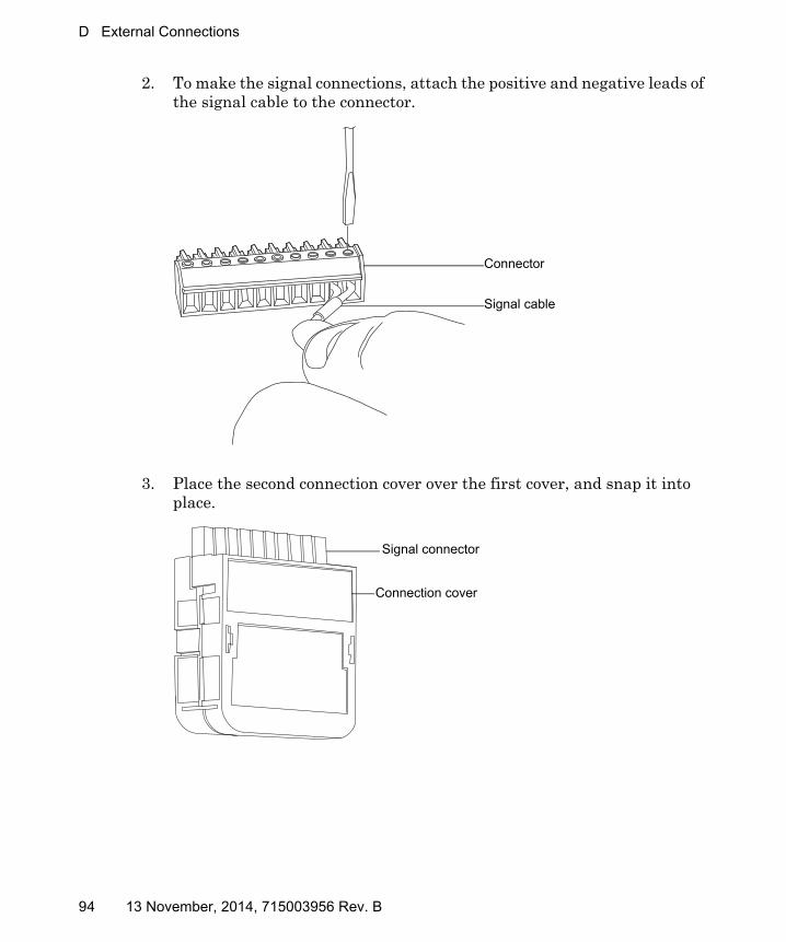
D External Connections
2. To make the signal connections, attach the positive and negative leads of the signal cable to the connector.
3. Place the second connection cover over the first cover, and snap it into place.
TP02585
Signal cable
Connector
TP02588
Signal connector
Connection cover
94 13 November, 2014, 715003956 Rev. B

Connecting to the power supply
Connecting to the power supply
To connect the instrument to the power supply, refer to page 22.
13 November, 2014, 715003956 Rev. B 95

D External Connections
96 13 November, 2014, 715003956 Rev. B