acquity uplc h-class - waters corporation...sm-ftn’s door is opened and turns off when the door is...
TRANSCRIPT

ACQUITY UPLC H-ClassSample Manager - Flow Through Needle Operator’s Overview and Maintenance
Information
Revision B
Copyright © Waters Corporation 2010All rights reserved

ii
Copyright notice
© 2010 WATERS CORPORATION. PRINTED IN THE UNITED STATES OF AMERICA AND IN IRELAND. ALL RIGHTS RESERVED. THIS DOCUMENT OR PARTS THEREOF MAY NOT BE REPRODUCED IN ANY FORM WITHOUT THE WRITTEN PERMISSION OF THE PUBLISHER.The information in this document is subject to change without notice and should not be construed as a commitment by Waters Corporation. Waters Corporation assumes no responsibility for any errors that may appear in this document. This document is believed to be complete and accurate at the time of publication. In no event shall Waters Corporation be liable for incidental or consequential damages in connection with, or arising from, its use.

Table of Contents
Copyright notice ................................................................................................... ii
Overview ................................................................................................................ 1 Location of SM-FTN in the ACQUITY UPLC H-Class system ......................... 1 Flow path through the sample management system......................................... 2 SM-FTN major components ................................................................................ 3 Functional systems .............................................................................................. 7 Injection mechanics ............................................................................................. 8
Preparing for operation ................................................................................... 12 Installing the leak sensor .................................................................................. 13 Installing the waste tubing ............................................................................... 14 Priming the SM-FTN......................................................................................... 16
Using the SM-FTN .............................................................................................. 17 Interface requirements ...................................................................................... 17 Installation recommendations for fittings........................................................ 18 Selecting purge and wash solvents ................................................................... 20 Washing the SM-FTN needle ............................................................................ 22 Loading sample plates ....................................................................................... 23 Sample chamber considerations ....................................................................... 27 Choosing needles and extension loops .............................................................. 27 Choosing the sample syringe............................................................................. 29 Choosing the sample syringe draw rate ........................................................... 29 Choosing the needle height setting................................................................... 30 Recovering maximum sample from vials.......................................................... 31 Revising a plate type ......................................................................................... 32 Air gaps .............................................................................................................. 33 Load-ahead and loop offline options ................................................................. 33 Auto dilution ...................................................................................................... 35 Diagnostic tests.................................................................................................. 35 Resolving leak sensor errors ............................................................................. 36
Table of Contents iii

Maintaining the SM-FTN .................................................................................. 39 Contacting Waters technical service................................................................. 39 Maintenance schedule ....................................................................................... 41 Maintenance considerations.............................................................................. 42 Configuring maintenance warnings ................................................................. 42 Replacing the leak sensor.................................................................................. 43 Replacing the seal .............................................................................................. 45 Replacing the sample needle and needle guide................................................ 58 Replacing the sample syringe ........................................................................... 66 Replacing the injection valve cartridge ............................................................ 70 Cleaning the instrument’s exterior................................................................... 72
iv Table of Contents

Overview
You can submit samples for analysis on the ACQUITY UPLC H-Class system by loading microtiter plates or vials onto the rotary sample tray of the sample manager-flow through needle (SM-FTN). Using a flow-through-needle mechanism, in which the needle is part of the high-pressure sample flow path, the sample manager injects the samples it draws from the plates and vials onto a chromatographic column. Optional extension loops (installed between the sample needle and the injection valve) increase the volume of your injections beyond that of the sample needle. Using the sample manager-flow through needle, you can also dilute injected samples (auto-dilution).
Location of SM-FTN in the ACQUITY UPLC H-Class systemThe following diagram shows the location of the SM-FTN in the ACQUITY UPLC H-Class system.
TP03241
Bottle tray
Detector
Column heater
Sample manager - flow through needle
Quaternary solvent manager
Overview 1

Tips:• Use care when stacking or moving the SM-FTN. Ensure the drip tray
does not collide with any surface.• Use care when installing and removing reusable fittings.
See also: Column Compartments Operator's Overview and Maintenance Information on the ACQUITY UPLC H-Class System Documentation CD to avoid potential leaks or carryover.
Flow path through the sample management systemThe following diagram shows how the SM-FTN functions as part of the ACQUITY UPLC H-Class system.
Drainage from column heater Wash solvent direct
from solvent bottle
Sample
Degassed solvent from QSM
Inject valve
Mobile phase from QSM
To column
QSM=Quaternary solvent manager
Secondary drainage to QSM
Secondary drainage to QSM
Primary drainage to QSM
Primary drainage to QSM
Sample syringe valve
2
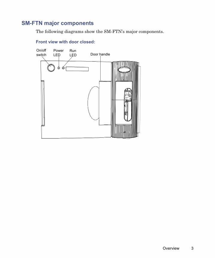
SM-FTN major componentsThe following diagrams show the SM-FTN’s major components.
Front view with door closed:
On/off switch
Power LED
Run LED Door handle
Overview 3

Front view, with door open:
Plate selector switch
Sample syringe
Location of sample manager leak sensor
Injection valve
Sample tray
Chamber temperature sensor Access panel
Sample syringe valve
Location of back pressure regulator
Location of column heater leak sensor
4

Sample compartment components visible with access panel removed:
SM-FTN components:
Component DescriptionAccess panel Removable panel (requires a TORX® driver) that
allows access to sample compartment components such as the seal assembly and needle carriage.
Compartment lighting
LED that illuminates the sample compartment. The compartment light automatically turns on when the SM-FTN’s door is opened and turns off when the door is closed. The light can also be turned off via the console to accommodate light-sensitive samples.
Inject/wash port An assembly that houses the injection port, needle seal, needle wash mechanism, and force sensor.
Location of sample needle
Inject/wash port
Inject port wash drain
Sample needle carriage
Location of wash tube
Compartment lighting
Location of column heater leak sensor cable connector
Location of sample manager leak sensor cable connector
Overview 5

Inject port wash drain
Directs the needle wash to waste.
Injection valve A two-position, six-port injection valve.Leak sensor Continuously monitors the SM-FTN for leaks and
stops the system flow when its optical sensor detects about 1.5 mL of accumulated, leaked liquid in its surrounding reservoir.
Plate selector switch Toggle switch used to select either plate position 1 or 2.
Sample syringe Draws sample into the sample needle.Sample syringe valve
A three-position, rotary-shear valve.
Sample needle Extracts sample from vials.Sample needle carriage
Positions the sample needle in the sample compartment.
Sample tray Secures the sample plates or vial holders in place.Chamber temperature sensor
Located on the rear wall of the sample chamber, to monitor sample environment.
Wash tube Delivers wash solvent to the inject/wash port.
SM-FTN components: (Continued)
Component Description
6

Functional systems
RΘ positioning mechanism
The RΘ (R-theta) positioning mechanism’s two axes control the orientation of the sample plates within the sample compartment and the relative position of the sample needle carriage. The theta-rotary axis is a belt-driven shaft that rotates a pair of sample plates 360° from a reference point. The R-linear axis is the axis along which the sample needle carriage is oriented. The carriage runs from the rear-left corner to the front-right corner of the sample compartment.
Injection system
The injection flow path includes the assemblies required to aspirate a sample and deliver it to the column. The process involves the needle, optional extension loop, sample syringe and syringe valve, injection valve, and injection/wash port.
Overview 7

Flow path diagram:
Injection mechanicsDuring an injection:
1. The needle is positioned and driven down by the R-carriage.
2. A PEEK support sleeve prevents buckling and helps ensure proper alignment with the seat.
3. The needle is driven into the seat to a specified force to form the first high-pressure seal.
4. The second high-pressure seal on the seat is formed during assembly when the seat is locked into place between the support sleeve and overflow cup via a compression nut.
Solenoid valve
Wash pump
InOut
Wash solvent
Purge solvent
SampleTo waste
Sample syringe
Pressure transducer
To waste
Union
Inject valve inject position
From pump
To column
Injection port
Sample compartment
8

5. The entire injection port assembly rests on a spring and is guided in an aluminum housing.
6. The needle presses against the seat, compressing the spring, which creates the required load between the needle and the seat.
Cross-view of injection needle and seal:
The following figures show a standard ACQUITY UPLC H-Class system cycle time and load-ahead cycle time.
NEEDLE
Needle motion
Force applied through the needle carriage
Needle
Seal
Overflow cup
Aluminum housing
Seal
High-pressure seal
Force sensor
Overview 9

Standard ACQUITY UPLC H-Class system cycle time definition:
Wash system
The wash system cleans the outside of the sample needle while it is inside the injection/wash port.You can choose two external needle washes, pre-injection or post-injection. Neither wash sequence allows wash solvent to enter the sample stream.
Pre-injection (insertion) washThe pre-injection wash washes the needle at a location above the seal position used for injection. The solvent begins to flow before the needle is lowered to this wash position.Choose to perform this wash if you are concerned about material on the outside of the sample needle damaging the seal or affecting the contact between the seal and the needle.
Post-injection (OD needle) washPerformed by default, this wash washes the exterior of the sample needle after an injection is made and the needle remains in the seal position.
Start End
SM-FTN sample preparationand positioning
Sample injection
Systemsetup
Standard injection mode
Total ACQUITY UPLC H-Class system cycle time
Chromatographic run time
Pre-wash Post-wash
10
Two priming modes are available:• Wash solvent prime, where the wash solvent flows through the wash
system to prime each component.• Purge solvent prime, where the degassed purge solvent flows through
the sample syringe.The purge solvent used for priming is also the solvent used to move sample through the injection flow path. During auto-dilution, the purge solvent is the dilution solvent.
Thermal system
The thermal system maintains the set temperature in the sample compartment.Tips:
• You do not need to defrost the sample compartment.• The SM-FTN’s fans stop circulating air whenever the sample
compartment door is open.• The sample tray rotates slowly when the system is idle, to help maintain
a uniform temperature across the plates.
Overview 11

Injection linearity
Preparing for operation
Note: The system is shipped with a 15-μL needle. If you are not using the default ACQUITY UPLC H-Class system configuration, which uses this needle, see page 39.Prepare the SM-FTN for operation after you prepare the quaternary solvent manager. Preparation involves these steps:
• Priming the sample syringe solvent• Priming the wash solvent• Prepare sample plates and load into sample compartment
Performance specifications for SM-FTN:
Item SpecificationInjection linearity (15-μL needle)
See system specifications information on the documentation CD.
Injection linearity (15-μL needle and 50-μL loop)
R2 = 0.999, caffeine, 1 injection per point, 10:90 acetonitrile/water, isocratic, 0.6 mL/min flow rate, 2 μL to 50 μL
Injection linearity 15-μL needle and 100-μL loop)
R2 = 0.999, caffeine, 1 injection per point, 10:90 acetonitrile/water, isocratic, 0.6 mL/min flow rate, 10 μL to 100 μL
Injection linearity 15-μL needle and 250-μL loop)
R2 = 0.999, caffeine, 1 injection per point, 10:90 acetonitrile/water, isocratic, 0.6 mL/min flow rate, 25 μL to 250 μL
12

Installing the leak sensor
Required materials
• Gloves: clean, powder-free, chemical-resistant• Leak sensor
To install the leak sensor:
1. Power-off the SM-FTN.
2. Open the device’s door, gently pulling its right-hand edge toward you.
3. Carefully unpack the new leak sensor.
Warning: To prevent injury, always observe Good Laboratory Practices when you handle solvents, change tubing, or operate the SM-FTN. Consult the Material Safety Data Sheets regarding the solvents you use.
Warning: The leak sensor can be contaminated with biohazardous and/or toxic materials. Always wear clean, chemical-resistant, powder-free gloves when performing this procedure.
Caution: To avoid damaging electrical parts, never disconnect an electrical assembly while power is applied to an instrument. To completely interrupt power, set the power switch to Off, and then unplug the power cord from the AC source. Wait 10 seconds thereafter before you disconnect an assembly.
Preparing for operation 13

4. Align the leak sensor’s T-bar with the slot in the side of the leak sensor reservoir, and slide the leak sensor into place.
5. Plug the leak sensor connector into the front of the instrument.
6. Power-on the SM-FTN.
7. In the ACQUITY UPLC Console, select Sample Manager FTN from the system tree.
8. In the SM-FTN information window, click Control > Reset SM, to reset the SM-FTN.
Installing the waste tubing
Required material
Gloves: clean, powder-free, chemical-resistant
Caution: To prevent contamination, wear clean, chemical-resistant, powder-free gloves when installing or removing the waste tubing.
TP02892
T-bar
Leak sensor installed in reservoir
Slot in leak sensor reservoir
14

To install the waste tubing:
1. Locate the pre-installed, corrugated tubing running from the process waste port (found on the lower drip tray of the sample manager), and route it through the pass-through on the upper drip tray of the quaternary solvent manager.
2. Slide the adapter onto the end of the corrugated Teflon® tubing.
3. Connect the adapter to the front boss fitting on the lower drip tray of the quaternary solvent manager.Tip: For instructions on routing the quaternary solvent manager waste and vent lines, see the Quaternary Solvent Manager Operator’s Overview and Maintenance Information.
Corrugated Teflon tubing
Process waste port
Pass-through on upper drip tray of the quaternary solvent manager
Front boss fitting on lower drip tray of the quaternary solvent manager
Preparing for operation 15

Priming the SM-FTNThe priming process fills the wash system with wash solvent or the injection pathway with purge solvent. You prime the system to accomplish these tasks:
• Prepare a new SM-FTN for operation• Prepare a SM-FTN for operation after it has been idle for an extended
period• Change the purge solvent• Remove bubbles from the lines
Ensure that the purge and wash solvents are correctly composed and that they are high in quality and miscible with any other solvents used in your system. Use filters in all solvent reservoirs, and ensure the volumes of solvents are sufficient for priming.
To prime the sample syringe:
1. In the ACQUITY UPLC Console, select Sample Manager FTN from the system tree.
SM-FTN information window:
2. Click Control > Prime.
16

Alternative: Right-click in the SM-FTN control panel, in the data application, and then click Prime.
3. In the Prime dialog box, click the boxes on the left-hand side, to place a check mark next to the priming function you want to perform.
4. Specify a duration, in seconds, for priming the wash solvent and the number of cycles for priming the purge solvent, and then click OK.
Recommendation: Specify 5 to 7 primes when you are changing solvents.Each priming cycle takes approximately 0.5 minutes. When the system status is “Idle,” priming is finished.
Using the SM-FTN
Before running samples,• examine the injection valve, sample syringe, and all fittings for leaks.
Tighten fittings as needed.• ensure both SM-FTN doors are closed.
Interface requirements
Ventilation
Allow at least 15.2 cm clearance at the rear and at least 1.3 cm clearance on the right-hand side of the SM-FTN for ventilation.
Priming parameter values:
Solvent Range DefaultWash solvent 1 to 600 seconds 15 secondsPurge solvent 1 to 50 cycles 5 cycles
Using the SM-FTN 17

Drainage system
• Allow clearance for fluid lines to pass along the right-hand side of the instrument (twelve 0.125” OD tubes or four 1/6” OD tubes, for example).
• Ensure that the SM-FTN can accept drainage from the column heater and provide a path to waste.
Installation recommendations for fittings
The system uses gold-plated compression screws and two-piece ferrules. See the diagram below for assembly orientation.
Recommendations:• To prevent bandspreading, ensure the tubing bottoms in its fitting hole
before tightening the compression screw.• For easier accessibility, use long compression screws to attach tubes to
the injector and vent valve.• Perform the sample syringe leak test whenever you replace or loosen
fittings during maintenance (see the ACQUITY UPLC online Help).
Warning: Fittings can be contaminated with biohazardous and/or toxic materials. Always wear clean, chemical-resistant, powder-free gloves when reinstalling fittings.
Caution: When installing or removing a column, be sure that you turn the column itself and not the fitting (compression screw and ferrule). If the fitting turns, the collet could become stuck and cause the active pre-heater tubing to turn with the fitting, potentially damaging the active pre-heater assembly.
TubingCompression screwFerrule with locking ring
18

• Whenever you loosen fittings during maintenance, examine them for cracks, stripped threads, and deformations.
• Do not reuse stainless steel fittings more than six times.
Required material
Gloves: clean, powder-free, chemical-resistantWhen tightening system fittings, consult the following table.
Installation recommendations for ACQUITY UPLC fittings:
Fitting Recommended tightening1/4-28 flangeless with ferrule Snug plus 1/6-turn
1/4-28 flangeless with 2-piece ferrule Snug plus 1/6-turn
10-32 LT135 PEEK with ferrule Snug plus 1/6-turn; if leaking, tighten another 1/8-turn
10-32 one-piece PEEK Finger-tight
1/6 turn
1/8 turn
Using the SM-FTN 19

Selecting purge and wash solvents
Purge solvent
The primary function of the purge solvent is to move sample along the injection pathway. The solvent comes into contact with the sample (as the dilution solvent) only when you choose the auto-dilution option. You also use purge solvent to prime the syringe.See also: “Priming the SM-FTN” on page 16
Stainless steel (gold plated) with 2-piece stainless steel ferrule (first use)
Finger-tight plus 3/4-turn with wrench
Stainless steel (gold plated) with 2-piece stainless steel ferrule (re-installed)
Finger-tight plus up to 1/6-turn with wrench
Reusable finger-tight (first use) Snug plus 1/6-turn
Reusable finger-tight (re-installed) Snug plus 1/6-turn; if leaking, tighten another 1/8-turn
Installation recommendations for ACQUITY UPLC fittings: (Continued)
Fitting Recommended tightening
3/4 turn
TP02728
Collet removal tool
20

Wash solvent
You can use wash solvent in an optional procedure that cleans the exterior of the needle before or after an injection. By default, the system washes the exterior of the needle after an injection. You can also prime the wash system with wash solvent to ascertain proper flow through the waste tubing and to confirm that the wash system is operating properly.See also: “Wash system” on page 10
General guidelines
For best performance, follow these guidelines when selecting purge and wash solvents. Otherwise, you can increase the risk of carryover. The guidelines do not prohibit all other solvent combinations, however, which you can run with lower performance expectations or by manipulating default injection parameters.Use purge and wash solvents based on the sample and mobile phase chemistries of your application. When you perform auto-dilutions, ensure purge solvent and sample solutions/buffers are miscible and soluble.For buffered aqueous, reversed-phase chromatographic conditions and MS applications, it is best to use a wash solvent of 100% methanol or acetonitrile or a mixture of methanol or acetonitrile with 0% to 20% water. Use a purge solvent with low organic content (~5% to 10%), to minimize dissolved gas while still preventing microbial growth.See the Solvent Considerations appendix in the ACQUITY UPLC H-Class System Guide for further information about solvents.
For best performance if you use the auto-dilution option, the purge solvent must be similar or identical to your isocratic or initial gradient solvent
Caution: To avoid damaging the solenoid valve seats and seals in the solvent path, do not use a nonvolatile buffer as the purge or wash solvent.
Using the SM-FTN 21

conditions, excluding buffers. Do not use salt buffers in purge or wash solvents.
Washing the SM-FTN needle
To wash the SM-FTN needle (OD needle wash):
1. In the ACQUITY UPLC Console, select Sample Manager FTN from the system tree.
2. In the SM-FTN information window, click Control > Wash Needle.
Wash solvent effects:
Property EffectOrganic species As a general principle, purge and wash solvents
must include the same organic species, which is not always practicable. You can, however, use a 100% organic wash solvent.
Solvent composition The purge solvent, if used for auto-dilution, must reflect as closely as possible the same composition as the initial gradient mobile phase.
pH Adjust the pH of the purge and wash solvents for best peak shape and carryover performance.
Concentration of wash solvent
Wash solvent must be no stronger than the concentration needed to reduce carryover to an acceptable level.
Solubility of sample The sample must be soluble in the purge solvent if you are performing auto-dilution.
Caution: Proteins (in plasma, for example) do not dissolve in solvents whose organic component is greater than 40%.
Sample diluent The purge solvent (diluent) will contact the sample, so match the sample matrix as closely as possible. To offset adverse effects on peak shape caused by the matrix’s composition, adjust the purge solvent composition.
Cycle times Higher viscosity wash solvents lengthen wash cycles.
22

Alternative: Right-click the SM-FTN control panel in the data application, and then click Wash Needle.
3. In the Needle Wash box, specify the wash duration, in seconds.Tips: • The range is 0 through 99 seconds; the default is 6 seconds.• The flow rate of the wash solvent is 20 mL/min +/- 20%.
4. Click OK. Result: The needle wash begins. When it ends, the status returns to idle.
To stop a needle wash routine before it finishes:
In the SM-FTN information window, click Control > Reset SM.Alternative: Right-click the SM-FTN control panel in the data application, and then click Reset SM.
Loading sample platesThe SM-FTN is compatible with the ANSI standard well-plates, vial-trays, vials, and cap-mats/seals that are approved for use with the ACQUITY UPLC H-Class system. The SM-FTN holds two ANSI/SBS plates that you load through the front door. Requirement: The plates you use must meet ANSI/SBS standards.Tip: Vial positions V1 through V4, located on the right-hand and left-hand sides of the sample tray, accommodate 4-mL vials. Contact Waters for inserts that allow you to use 2-mL vials in these positions.
Using the SM-FTN 23

Observing vial and plate recommendations
Waters recommends that you observe these guidelines for loading sample vials and plates in the SM-FTN:
• Use only Waters-certified vials.• Use only 1860024XX-series plates and cap mats in the SM-FTN.• Use pre-slit cap-mats/seals and vial caps. • Use foil covers on vial plates whenever possible.• Always measure other manufacturers’ plates to determine their
suitability for use in the SM-FTN.• To avoid warping plates, do not centrifuge them.• When selecting a new plate supplier, especially for size 384 plates,
always compare the plate size with Waters’ specifications.
Required material
Safety glasses
Caution: • Use of non-pre-slit cap mats and vial caps can cause
clogging in the wash lines.• Vial holders must conform to ANSI/SBS standards. • To prevent sample spillage or needle damage, use only
Waters-approved covers on the sample vials. • Do not put plates in a centrifuge. • Plates containing samples with high concentrations of
organic solvent can give inconsistent results at room temperature.
Warning: To avoid eye injury, wear safety glasses when loading sample plates.
24

To load a sample plate:
1. Open the SM-FTN’s door, gently pulling its right-hand edge toward you.
2. Press the plate selector switch on the top, center of the door frame to select plate position 1 or 2.Exception: If the SM-FTN is accessing the sample tray when you select a new plate position, the selector switch does not operate and the instrument beeps once. The selector switch operates again after the SM-FTN no longer accesses the sample tray.Tip: Press the plate selector switch twice to toggle between loading a sample plate and loading positions that accept 4-mL vials.
3. Pull the sample tray out.
4. Load the plate onto the tray so that well position A,1 is at the rear, left-hand corner, and the forward edge of the plate is behind the spring inside the front of the carrier.
Sample tray pulled out
Position for a 4-mL vial (V1 through V4)
Using the SM-FTN 25

Tip: “A” represents the row number, “1” represents the vial position.
Sample plate vial positions:
TP03232
Sample plate
A,1 well position
1 2 3 4 5 6 7 8
A
B
C
D
E
F
26
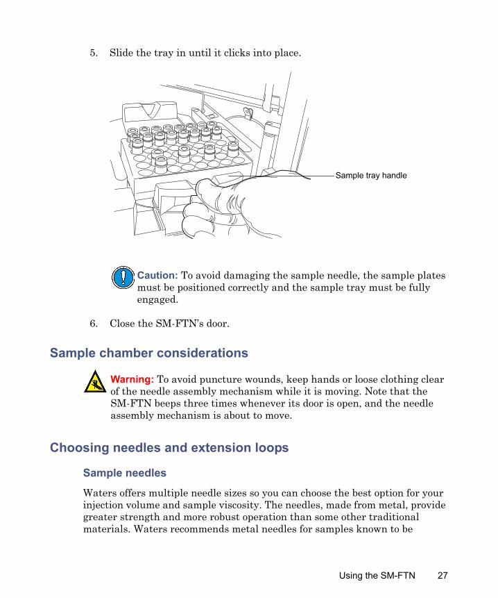
5. Slide the tray in until it clicks into place.
6. Close the SM-FTN’s door.
Sample chamber considerations
Choosing needles and extension loops
Sample needles
Waters offers multiple needle sizes so you can choose the best option for your injection volume and sample viscosity. The needles, made from metal, provide greater strength and more robust operation than some other traditional materials. Waters recommends metal needles for samples known to be
Caution: To avoid damaging the sample needle, the sample plates must be positioned correctly and the sample tray must be fully engaged.
Warning: To avoid puncture wounds, keep hands or loose clothing clear of the needle assembly mechanism while it is moving. Note that the SM-FTN beeps three times whenever its door is open, and the needle assembly mechanism is about to move.
Sample tray handle
Using the SM-FTN 27

attracted to hydrophobic polymers and also when you use hexane and tetrahydrofuran.Tip: Using a smaller needle increases cycle times.
Extension loops
Extension loops, which increase the volume of sample that can be drawn and held for injection, are an optional part of the injection system. You install them between the needle and the injection valve port.
Modifying needle and extension loop configuration parameters
To configure the system for a needle or extension loop size that differs from the one currently fitted:
1. In the ACQUITY UPLC Console, select Sample Manager FTN from the system tree.
2. Select Configure > Volumes.
3. In the Volume Configuration dialog box, select the appropriate needle or extension loop size from the list, and then click OK.
The following metal sample needles are available for the SM-FTN:
Needle size Recommended maximum injection volume
15-μL (24” L x 0.007” ID) – Default 10 μL30-μL (24” L x 0.010” ID) 25 μL
The following extension loops are available to use in the SM-FTN:
Loop size Recommended maximum injection volume with any size needle
50 μL 50 μL100 μL 100 μL250 μL 250 μL
28

Choosing the sample syringeThe following sample syringe sizes are available to use in the SM-FTN:
• 50 μL• 100 μL – Default• 250 μL• 500 μL
Choose a syringe size that allows you to draw your desired total sample volume into the sample needle (and optional extension loop). Waters recommends using a sample syringe volume that is at least two times your sample volume.
Modifying sample syringe configuration parameters
To configure the system for a syringe size that differs from the one currently fitted:
1. In the ACQUITY UPLC Console, select Sample Manager FTN from the system tree.
2. Select Configure > Volumes.
3. In the Volume Configuration dialog box, select the appropriate sample syringe size from the list, and then click OK.
Choosing the sample syringe draw rateThe ideal syringe draw rate depends on sample volume, sample viscosity, and desired cycle time. You can also specify the draw rate (in μL/min), if desired.
Maximum syringe draw rates for the 15-μL needle (0.007” ID):
Extension loop volume
Solvent TypeNo extension loop
50 μL 100 μL 250 μL
50:50 methanol/water
30 μL/min 30 μL/min 30 μL/min 30 μL/min
100% water 55 μL/min 55 μL/min 55 μL/min 55 μL/min
Using the SM-FTN 29

Choosing the needle height settingThe default setting for needle penetration depth prevents you from reaching the bottom of the vial.
You can change the default needle placement (needle height) setting in the software in two places: the Dilution tab of the Sample Manager instrument method editor and the Advanced Settings dialog box. Set consistent values in both places.
100% acetonitrile 150 μL/min 150 μL/min 150 μL/min 150 μL/min100% dimethyl sulfoxide (DMSO)
25 μL/min 25 μL/min 25 μL/min 25 μL/min
Maximum syringe draw rates for the 30-μL needle (0.010” ID):
Extension loop volume
Solvent TypeNo extension loop
50 μL 100 μL 250 μL
50:50 methanol/water
120 μL/min 120 μL/min 120 μL/min 120 μL/min
100% water 230 μL/min 230 μL/min 230 μL/min 230 μL/min100% acetonitrile 640 μL/min 640 μL/min 640 μL/min 640 μL/min100% dimethyl sulfoxide (DMSO)
100 μL/min 100 μL/min 100 μL/min 100 μL/min
Caution: To avoid damaging the needle, follow the guidelines in this section, and use the appropriate needle-height setting for your sample plates or vials.
Maximum syringe draw rates for the 15-μL needle (0.007” ID): (Continued)
Extension loop volume
Solvent TypeNo extension loop
50 μL 100 μL 250 μL
30

To aspirate more sample from the vial, decrease the value so that the needle tip is closer to the bottom of the vial.Tips:
• The default needle-height setting for 48-vial plates is “automatic”, which is set at 4.0 mm.
• The default needle-height setting for all other plates is 2.0 mm.
Recovering maximum sample from vialsThe current ANSI plate (48 vials) definition for the 2-mL Maximum Recovery Vials can leave some sample in the vial. If you want to recover the maximum amount of sample, change the needle placement setting. Tip: To modify needle placement for vials, click Instrument Method Editor > ACQ-FTN > General tab > Advanced, and change the “Needle Placement (from bottom)” value.
Vial type
Minimum needle placement (mm)
Description Part number
Waters Supplied Total Recovery Vial
0.7 Screw Cap 12 × 32 mm Clear Total Rec pre-slit PTFE/Silicone Septa
186000385C
Vial depth
Sample needle
2 mm offset
Using the SM-FTN 31

See also: Waters Sample Vials and Accessories brochure on www.waters.com.
Revising a plate typeThe ANSI-48Tube0.65mLHolder plate type is defined in Empower software so that the needle does not use sample near the bottom of the vial, greatly increasing the residual volume. The plate type contains 0.65 mL tubes.
To create a new plate type and correct the depth value:
1. In Empower software, open the Configure System window.
2. From the Empower Configuration tree, select Plate Types.
3. Select the plate type “ANSI-48Tube0.65mLHolder”.
4. From the menu, select File > Properties.
Waters Supplied Max. Recovery Vial
2.1 Screw Cap 12 × 32 mm Clear Max Rec pre-slit PTFE/Silicone Septa
186000327C
Screw Cap 12 × 32 mm Amber Max Rec pre-slit PTFE/Silicone Septa
186003886C
Waters Supplied Flat Bottom Vial
0.1 Screw Cap 12 × 32 mm Clear with pre-slit PTFE/Silicone Septa
186000307C
Screw Cap 12 × 32 mm Amber pre-slit PTFE/Silicone Septa
186000847C
Screw Cap 12 × 32 mm 750 µL PP pre-slit PTFE/Silicone Septa
186002636
Screw Cap 12 × 32 mm 300 µL PP pre-slit PTFE/Silicone Septa
186002639
Vial type
Minimum needle placement (mm)
Description Part number
32

5. Under Plate Type, type a suitable name for the plate.
6. Change the Depth parameter to 28.5.
7. Click OK. Result: A copy of the plate definition is created with a new name and revised needle depth.
Air gapsIf air gaps are required for your chromatography, you can specify an air-gap volume in the instrument method editor. The default air-gap volume is 0 μL.
To specify an air-gap volume:
1. In the instrument method editor, click the ACQ-FTN tab and then the General tab.
2. Click Advanced.
3. In the Advanced Settings dialog box, mark the box for the air-gap option.
4. Specify volumes for your pre-aspirate and post-aspirate air gaps, and then click OK.
Load-ahead and loop offline options
Load ahead
The load-ahead option instructs the sample manager to aspirate the next sample in a sample list while a current sample is running.Requirement: You must take the extension loop off-line when you use the load-ahead option.
Loop offline
The loop-offline option can improve chromatographic performance by producing a sharp trailing sample edge as the sample leaves the needle and extension loop. Choose it to specify an interval, in minutes, following an injection, after which the needle and extension loop return to the load position. Doing so reduces the delay volume by taking the needle and extension loop offline before the gradient reaches the injection valve and after the sample transfers to the injection port.
Using the SM-FTN 33

ACQUITY UPLC H-Class system load-ahead cycle time definition:
Tip: The time buffer delay is a “wait time” that compensates for variations in the time it takes to load a sample.The minimum cycle time is the lesser of either the two run times or sample preparation and wash.Exception: The first injection of a sample set, and injection sets with different methods, can not utilize load-ahead mode.
To choose the load-ahead and loop-offline options:
1. In the instrument method editor, click the ACQ-FTN tab and then the General tab.
2. Mark the boxes for the load-ahead and loop-offline options.
3. Specify a time interval for the loop-offline option, if necessary.Tip: In the SM-FTN, a programmed gradient typically flows through all parts of the instrument that contact the sample. If you initiate the loop-offline option before the gradient reaches its final conditions, the highly organic portion of your gradient does not pass through the needle. As a result, the gradient can fail to remove all sample from the needle – resulting in low sample recovery and an increased risk of carryover.
EndStart
Sample injection
Total ACQUITY UPLC H-Class system cycle time
Load-ahead mode after the first injection
Chromatographic run time
SM-FTN sample preparation
SM-FTN wash time
Time buffer delay
System setup and sample positioning
Loop comes offline
34

Auto dilutionChoose the auto-dilution option to dilute dissolved samples (containing no solids) with a solvent the sample syringe delivers. You can specify an interval, to allow time for sample mixing.
To choose the dilution option:
1. In the instrument method editor, click the ACQ-FTN tab and then the Dilution tab.
2. Mark the box to Enable dilution.
3. Specify a needle height, purge solvent volume, and a post dilution delay interval.
Diagnostic testsYou can select these diagnostic tests from the SM-FTN’s Maintain menu:
• Needle seal readiness test, which verifies that, when the needle is in the “seal” position and the injection valve is in the “inject” position, no unacceptable drop in solvent pressure occurs.
• Sample syringe leak test, which verifies the sample path is free of leaks.The Maintain menu also lists these functions:
• Characterizing the needle seal, which determines the seal location.• Calibrating the needle’s Z-axis, which calibrates the vertical position of
the needle.• Disabling motors, which you do before manually moving the sample tray
and R-carriage.• Parking the sample needle and injection valve, which you do before
storing the system, or replacing a needle or valve.• Replacing the needle, seal, and sample syringe
See also: • Quaternary Solvent Manager Operator’s Overview and Maintenance
Information for information on the quaternary solvent manager’s leak test.
• ACQUITY Console online Help for additional information about running diagnostic tests.
Using the SM-FTN 35

Resolving leak sensor errorsThe SM-FTN is the only ACQUITY UPLC H-Class instrument fitted with two leak sensors, bottom and top: called the SM-FTN leak sensor and the column heater leak sensor, respectively.After approximately 1.5 mL of liquid accumulates in the leak sensor reservoir, an alarm sounds indicating that the leak sensor detected a leak.
Required materials
• Cotton swabs• Gloves: clean, powder-free, chemical-resistant• Nonabrasive, lint-free wipes
To resolve a leak sensor error:
1. In the ACQUITY UPLC Console’s Leak Sensors dialog box, determine which of the SM-FTN’s 2 leak sensors detected a leak.
2. If the message reads “Leak Detected”, locate the source of the leak, and make the repairs necessary to stop it. If you need additional information, see the Column Compartments Operator’s Overview and Maintenance Information document.
Warning: The leak sensor can be contaminated with biohazardous and/or toxic materials. Always wear clean, chemical-resistant, powder-free gloves when performing this procedure.
Caution: To avoid scratching or damaging the leak sensor• do not allow buffered solvents to accumulate and dry on it.• do not submerge it in a cleaning bath.
36

3. Remove the leak sensor from its reservoir, grasping it by its serrations, and pull upward on it.
Tip: If you cannot easily manipulate the leak sensor after removing it from its reservoir, detach the connector from the front of the device (see page 43).
4. Use a nonabrasive, lint-free wipe to dry the leak sensor prism.
Caution: To avoid damaging the leak sensor, do not grasp it by the ribbon cable.
Serrations
TP02891
Prism
Lint-free wipe
Using the SM-FTN 37

5. Roll up a nonabrasive, lint-free wipe, and use it to absorb the liquid from the leak sensor reservoir and its surrounding area.
6. With a cotton swab, absorb any remaining liquid from the corners of the leak sensor reservoir and its surrounding area.
Rolled up lint-free wipe
Leak sensor reservoir
Cotton swabLeak sensor reservoir
38

7. Align the leak sensor’s T-bar with the slot in the side of the leak sensor reservoir, and slide the leak sensor into place.
8. If you detached the connector from the front of the instrument, reattach it.
9. In the ACQUITY UPLC Console, select Sample Manager FTN from the system tree.
10. In the SM-FTN information window, click Control > Reset SM, to reset the SM-FTN.
Maintaining the SM-FTN
Contacting Waters technical serviceIf you are located in the USA or Canada, report malfunctions or other problems to Waters Technical Service (800 252-4752). Otherwise, phone the Waters corporate headquarters in Milford, Massachusetts (USA), or contact
TP02892
T-bar
Leak sensor installed in reservoir
Slot in leak sensor reservoir
Maintaining the SM-FTN 39

your local Waters subsidiary. The Waters Web site includes phone numbers and e-mail addresses for Waters locations worldwide. Visit www.waters.com.When you contact Waters, be prepared to provide this information:
• Error message (if any)• Nature of the malfunction• Instrument serial numbers (see page 40)• Flow rate• Operating pressure• Solvent(s)• Detector settings (sensitivity and wavelength)• Type and serial number of column(s)• Sample type• Data application version and serial number• ACQUITY UPLC H-Class system workstation model and operating
system versionFor complete information on reporting shipping damages and submitting claims, see the document Waters Licenses, Warranties, and Support Services.
Locating system serial numbers
Each system instrument or device bears a serial number that facilitates service and support. Serial numbers also provide a way to create single log entries for each instrument so that you can review the usage history of a particular unit.Be prepared to provide the serial numbers of the instruments in your system when you contact Waters customer support.
To view instrument information:
1. In the ACQUITY UPLC Console, select an instrument from the system tree.
2. Click Configure > View module information. The Module Information dialog box displays this information: • Serial number• Firmware version
40

• Firmware checksum• Component software version
Alternatives:• From the main window, hover the pointer over the visual representation
of the system instrument or device you want information about.• Obtain the serial number from the printed labels on the instrument or
device’s rear panel or inside its front door.
Maintenance scheduleWaters recommends that you perform the following routine maintenance on the SM-FTN to ensure reliable operation and accurate results. When using the system throughout the day (and on nights and weekends), or when using aggressive solvents such as buffers, perform these maintenance tasks more frequently.
Recommended routine maintenance schedule:
Maintenance procedure Frequency For information...Replace the leak sensor As needed See page 43.Replace the seal During scheduled
routine maintenance or as needed
See page 45.
Replace the sample needle and needle guide
During scheduled routine maintenance or as needed
See page 58.
Replace the sample syringe During scheduled routine maintenance or as needed
See page 66.
Replace the injection valve cartridge
During scheduled routine maintenance or as needed
See page 70.
Clean the instrument with a soft, lint-free cloth, or paper dampened with water
As needed See page 72.
Maintaining the SM-FTN 41
Maintenance considerations
Safety and handling
Observe these warning and caution advisories when you perform maintenance operations on your system.
Proper operating procedures
To ensure your system runs efficiently, follow the procedures on page 12.
Configuring maintenance warningsMaintenance counters provide real-time usage status information that can help you determine when to schedule routine maintenance for specific components. You can set usage thresholds and maintenance warnings that alert you when a component reaches the designated threshold limit. By setting threshold limits and monitoring these usage counters regularly, you can minimize unexpected failures and unscheduled downtime during important work. For information on setting maintenance warnings, consult the ACQUITY UPLC Console online Help.
Warning: To prevent injury, always observe Good Laboratory Practices when you handle solvents, change tubing, or operate the SM-FTN. Consult the Material Safety Data Sheets regarding the solvents you use.
Warning: To avoid electric shock, do not remove the instrument’s protective panels. The components within are not user-serviceable.
Caution: To avoid damaging electrical parts, never disconnect an electrical assembly while power is applied to an instrument. To completely interrupt power, set the power switch to Off, and then unplug the power cord from the AC source. Wait 10 seconds thereafter before you disconnect an assembly.
42

Replacing the leak sensor
Required materials
• Gloves: clean, powder-free, chemical-resistant• New leak sensor
To replace the leak sensor:
1. Open the SM-FTN’s door, gently pulling its right-hand edge toward you.
2. Press down on the tab to detach the leak sensor connector from the front of the instrument.
Warning: The leak sensor can be contaminated with biohazardous and/or toxic materials. Always wear clean, chemical-resistant, powder-free gloves when performing this procedure.
Leak sensor connector
Press down on tab to release connector
Maintaining the SM-FTN 43

3. Remove the leak sensor from its reservoir, grasping it by its serrations, and pull upward on it.
4. Carefully unpack the new leak sensor.
5. Align the leak sensor’s T-bar with the slot in the side of the leak sensor reservoir, and slide the leak sensor into place.
6. Plug the leak sensor connector into the front of the SM-FTN.
Serrations
TP02892
T-bar
Leak sensor installed in reservoir
Slot in leak sensor reservoir
44

7. In the ACQUITY UPLC Console, select Sample Manager FTN from the system tree.
8. In the SM-FTN information window, click Control > Reset SM, to reset the SM-FTN.
Replacing the seal
Required materials
• 5/16-inch open-end wrench• 1/4-inch open-end wrench• 1/2-inch open-end wrench• T10 TORX driver• T20 TORX driver• Gloves: clean, powder-free, chemical-resistant• Seal kit
To replace the seal:
1. In the ACQUITY UPLC Console, select Sample Manager-FTN from the system tree.
2. Click Maintain > Replace > Seal. Result: Doing so moves the needle carriage towards the back of the sample compartment.
3. Open the SM-FTN’s door.
Warning: The seal can be contaminated with biohazardous and/or toxic materials. Always wear clean, chemical-resistant, powder-free gloves when performing this procedure.
Maintaining the SM-FTN 45
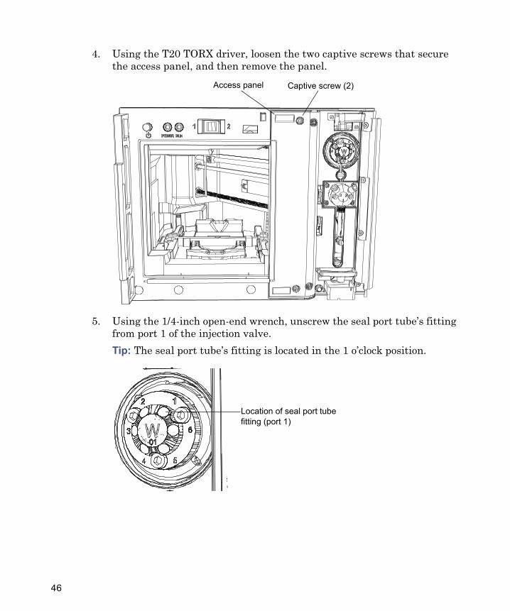
4. Using the T20 TORX driver, loosen the two captive screws that secure the access panel, and then remove the panel.
5. Using the 1/4-inch open-end wrench, unscrew the seal port tube’s fitting from port 1 of the injection valve.Tip: The seal port tube’s fitting is located in the 1 o’clock position.
Captive screw (2)Access panel
Location of seal port tube fitting (port 1)
46

6. Using the T10 TORX driver, remove the screw that secures the seal assembly to the sample compartment floor, lift the assembly upward, and remove it and the seal port tube from the sample compartment.
7. Unscrew the finger-tight wash tube fitting from the finger-tight wash fitting.
8. Unscrew the finger-tight wash fitting from the seal assembly.
Screw
Seal assembly
Wash fitting
Location of wash tube fitting
Maintaining the SM-FTN 47
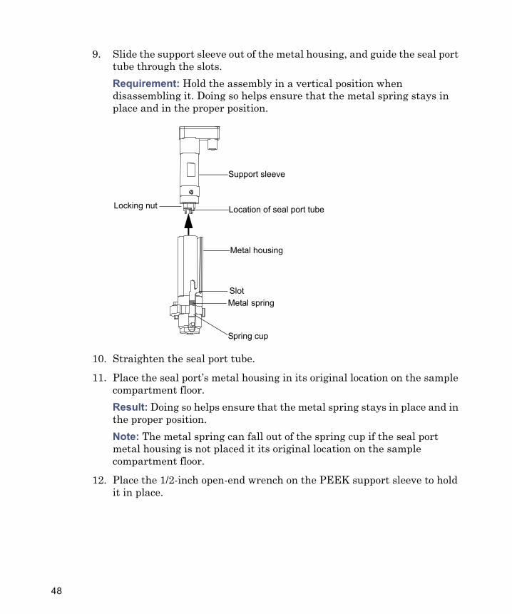
9. Slide the support sleeve out of the metal housing, and guide the seal port tube through the slots. Requirement: Hold the assembly in a vertical position when disassembling it. Doing so helps ensure that the metal spring stays in place and in the proper position.
10. Straighten the seal port tube.
11. Place the seal port’s metal housing in its original location on the sample compartment floor. Result: Doing so helps ensure that the metal spring stays in place and in the proper position.Note: The metal spring can fall out of the spring cup if the seal port metal housing is not placed it its original location on the sample compartment floor.
12. Place the 1/2-inch open-end wrench on the PEEK support sleeve to hold it in place.
Support sleeve
Metal springSlot
Metal housing
Location of seal port tube
Spring cup
Locking nut
48

13. Place the 5/16-inch open-end wrench on the stainless steel locking nut.
14. Loosen the locking nut, and unscrew it from the support sleeve.
Place 1/2-inch open-end wrench here
Place 5/16-inch open-end wrench here
Location of seal port tube
Support sleeve
Locking nut
Tube/port assembly
Maintaining the SM-FTN 49

15. Remove the seal from the seal port, and discard the seal.
Caution: To prevent contamination, wear clean, chemical-resistant, powder-free gloves and work on a clean surface when replacing the seal.
Seal
Locking nut
Seal port
50

16. Insert the new seal into the seal port. The seal is keyed, ensuring that it will only install one way, as shown below.
Seal
Locking nut
Smaller diameter end
Seal port
Notch
Seal
Align notch with pin in seal cup
Pin
Seal cup
Maintaining the SM-FTN 51
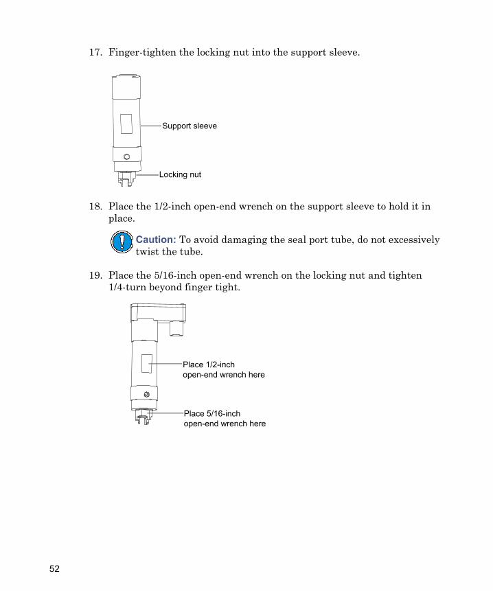
17. Finger-tighten the locking nut into the support sleeve.
18. Place the 1/2-inch open-end wrench on the support sleeve to hold it in place.
19. Place the 5/16-inch open-end wrench on the locking nut and tighten 1/4-turn beyond finger tight.
Caution: To avoid damaging the seal port tube, do not excessively twist the tube.
Support sleeve
Locking nut
Place 1/2-inch open-end wrench here
Place 5/16-inch open-end wrench here
52

20. Bend the line 90 degrees in line with the threaded hole in the support sleeve.Note: To avoid interfering with the motion of the metal spring in the metal housing, the bend in the seal port tube must not extend beyond the step in the locking nut.
21. Slide the seal port tube into the slot on the side of the metal housing.
Requirement: Ensure the three prongs on the locking nut are seated inside the metal spring.
Support sleeve
Step in locking nut
Threaded hole
Support sleeve
Metal springSlot
Metal housing
Location of seal port tube
Spring cup
Maintaining the SM-FTN 53

Prongs on locking nut correctly seated inside metal spring:
22. Slide the support sleeve into the metal housing, ensuring the fitting hole on the support sleeve aligns with the slot on the metal housing.
SpringProng (3)
Locking nut
Fitting hole
Slot
54

23. Screw the wash fitting finger-tight into the support sleeve.
24. Screw the wash tube fitting into the wash fitting, and tighten it finger-tight plus 1/4-turn.
Caution: To avoid damaging the support sleeve, be careful not to cross-thread the wash fitting.
Wash fitting
Wash fitting
Location of wash tube fitting
Maintaining the SM-FTN 55

25. Adjust the amount of tubing in the sample compartment by sliding it in and out of the foam.Tip: The wash tube is secured to the wall and should not interfere with the sample tray operation or vertical motion of the wash port.
26. Place the seal assembly in its original location on the sample compartment floor and align the screw hole with the hole in the floor, ensuring the inject port wash drain is in the needle wash basin.Tip: There are unused holes in the sample compartment floor.
27. Using the T10 TORX driver, tighten the screw that secures the seal assembly to the sample compartment floor.
28. Ensure all cables are routed so they do not interfere with the operation of the needle carriage home sensor.Using gentle radius bends, route the seal port tube to the right, following straight up the right side edge of the sample compartment. The seal port tube must be routed in the middle of the wash fitting and
Screw
Seal assembly
Inject port wash drain
Needle wash basin
56

the load cell cable. Ensure the cable exits the inject port assembly without any tight bends in front of the load cell cable.
29. Using gentle radius bends, route the seal port tube behind the needle tube and to the right.
30. Screw the seal port’s fitting into port 1 of the injection valve, and then use the 1/4-inch open-end wrench to tighten the fitting 1/4-turn past finger-tight.
31. Reinstall the access panel using the T20 TORX driver to tighten the two screws that secure the panel to the front of the unit.
Caution: To avoid errors in operation, ensure that the load cell cable is routed behind the seal port tube and the wash tube.
Location of seal port tube fitting (port 1)
Maintaining the SM-FTN 57

Requirement: Ensure that the seal port tube is routed under the gap on the side of the access panel.
32. Close the SM-FTN’s door.
33. Characterize the needle seal (see the ACQUITY UPLC online Help).
34. Perform the needle seal readiness test (see the ACQUITY UPLC online Help).
Replacing the sample needle and needle guide
Required materials
• T6 TORX driver• T10 TORX driver• T20 TORX driver
Warning: The sample needle and needle guide can be contaminated with biohazardous and/or toxic materials. Always wear clean, chemical-resistant, powder-free gloves when performing this procedure.
Access panel gap
58

• Gloves: clean, powder-free, chemical-resistant• Needle assembly kit
To replace the sample needle and needle guide:
1. In the ACQUITY UPLC Console, select Sample Manager-FTN from the system tree.
2. Click Maintain > Replace > Needle. Result: Doing so invokes a wizard that moves the sample needle assembly to an accessible position.
3. Open the SM-FTN’s door.
4. Using a T20 TORX driver, loosen the two captive screws that secure the access panel, and then remove the panel.
5. Remove the sample plate if a plate is loaded.
Captive screw (2)Access panel
Maintaining the SM-FTN 59

6. Unscrew the needle assembly’s fitting from injector port 4.
ACQUITY UPLC H-Class sample needle assembly:
7. Inside the sample compartment, open the needle-tubing guide cover, located on the roof of the compartment, by rotating it clockwise.
Fitting ID sleeveMounting sleeve Needle tip
Mounting cylinder
Location of needle assembly’s fitting (port 4)
Guide cover Guide channelNeedle tubing
60

8. Push the needle latch back, to release the needle mounting cylinder from its mounting cavity and the needle tubing from its notches.
9. Lift the needle tip out of the needle guide at the bottom of the needle mechanism.
Needle latch NotchesMounting cavity
Needle guide
Needle
Maintaining the SM-FTN 61

10. Using a T10 TORX driver, loosen the screw on the needle-tubing clamp and remove the tubing.
11. Using the T6 TORX driver, loosen the needle guide set screw, and then remove the needle guide.
12. Install the new needle guide, and tighten the set screw.
Warning: To avoid puncture wounds, or damage to the end of the needle, do not touch or press the end of the sample needle.
Remove needle assembly from this clamp
Clamp screw
Set screw
Needle guide
62

13. Holding the new needle assembly with both hands to control its position within the sample compartment, secure the mounting sleeve in the opening of the tubing clamp, with the fitting oriented toward the valve.
ACQUITY UPLC H-Class sample needle assembly:
14. From inside the sample compartment, take hold of the needle assembly tubing as it enters the compartment from above.
Caution: To avoid letting go of the needle assembly and possibly damaging the tip of the needle, do not tighten the clamp screw during this step of the procedure.
Fitting ID sleeveMounting sleeve Needle tip
Mounting cylinder
Secure mounting sleeve in this clamp
Maintaining the SM-FTN 63

15. Ensure the needle tubing is routed to the left side of the needle carriage’s rails and is secured in the guide channel on the roof of the compartment.
16. Remove the protective cap from the needle tip.
17. Insert the needle mounting cylinder into the mounting cavity.
18. Route the tubing through the two notches below the Z-flag.
Caution: To avoid damaging the instrument, do not place the loose loop of tubing above the Z-flag.
Guide coverGuide channel Needle tubing
NotchesMounting cavity
Do not loop needle tubing above Z-flag
64

19. Push the needle latch forward to secure the needle assembly.
20. Using a T10 TORX driver, tighten the screw on the needle-tubing clamp.
21. Insert the needle’s tip into the needle guide at the bottom of the needle mechanism.
22. Ensure that the needle tubing is fully inserted into port 4, on the injection valve, and then thread the fitting into the port, tightening the fitting securely.
23. Reinstall the access panel, using the T20 TORX driver to tighten the two screws that secure it to the front of the unit.
Needle latchNotches
Insert needle tip here
Maintaining the SM-FTN 65

Requirement: Ensure that the seal port tube is routed under the gap on the side of the access panel.
24. Close the SM-FTN’s door.
25. Calibrate the needle’s Z axis (see the ACQUITY UPLC online Help).
26. Characterize the needle seal (see the ACQUITY UPLC online Help).
27. Perform the needle seal readiness test (see the ACQUITY UPLC online Help).
Replacing the sample syringe
Recommendation: Perform the sample syringe leak test whenever you replace the sample syringe (see the ACQUITY UPLC online Help).
Warning: The sample syringe can be contaminated with biohazardous and/or toxic materials. Always wear clean, chemical-resistant, powder-free gloves when performing this procedure.
Access panel gap
66

Air bubbles in the sample syringe adversely affect system pressure, baseline, volume, and peak area.
Replace the sample syringe when any of these conditions arise:• The syringe plunger tip becomes worn or discolored• You want to change to the other syringe size• The syringe leaks or causes air bubbles• The syringe fails the leak test
Required materials
• Degassed, weak wash solvent• Gloves: clean, powder-free, chemical-resistant• Replacement sample syringe
To replace the sample syringe:
1. In the ACQUITY UPLC Console, select Sample Manager FTN from the system tree.
2. Click Maintain > Replace > Sample syringe > OK. Result: Doing so invokes a wizard that moves the syringe to the “down” position.
Caution: To avoid breaking the sample syringe, do not attempt to remove air bubbles from the syringe by tapping on it.
Warning: To avoid injury, ensure that no injection is in progress or pending before you remove the sample syringe.
Maintaining the SM-FTN 67

3. Remove the knurled screw that holds the sample syringe to the syringe mounting bracket.
Sample syringe assembly components:
4. Unscrew the sample syringe, counterclockwise, until it separates from the sample syringe valve.
Caution: To avoid breaking the syringe, do not grasp it by its glass barrel. Always grasp the syringe by its knurled collar.
Sample syringe valve
Sample syringe
Knurled screw
Knurled collar
68

5. Depress the syringe barrel to clear the top mounting bracket, and remove the syringe.
6. Carefully unpack the replacement sample syringe.
7. Partially fill the new syringe (by hand) with weak wash solvent (to help remove air bubbles).Requirement: Make sure all air bubbles are removed.
8. Retract the syringe plunger so that the plunger end slides over the threaded post on the syringe guide mounting bracket.
9. Screw the new sample syringe partially into the sample syringe valve.
10. Finger-tighten the sample syringe.
11. Install and finger-tighten the knurled screw that holds the sample syringe plunger to the mounting bracket.
12. Run the Prime Sample Syringe Only option until no air bubbles remain in the sample syringe.Tip: Tap the sample syringe while pushing on the plunger to remove air.
Sample syringe valve
Mounting bracket
Threaded holder
Syringe plunger
Knurled collar
Maintaining the SM-FTN 69

Replacing the injection valve cartridge
Requirement: When you replace the injection valve, you must also replace the sample loop.
Required materials
• 2-mm Allen wrench• Gloves: clean, powder-free, chemical-resistant• Injection valve cartridge
To replace the injection valve cartridge:
1. In the ACQUITY UPLC Console, select Sample Manager FTN from the system tree.
2. In the SM-FTN information window, click Maintain > Park needle and inject valve > Yes.
3. Power-off the SM-FTN.
Warning: The injection valve cartridge can be contaminated with biohazardous and/or toxic materials. Always wear clean, chemical-resistant, powder-free gloves when performing this procedure.
Caution: To avoid damaging electrical parts, never disconnect an electrical assembly while power is applied to an instrument. To completely interrupt power, set the power switch to Off, and then unplug the power cord from the AC source. Wait 10 seconds thereafter before you disconnect an assembly.
70
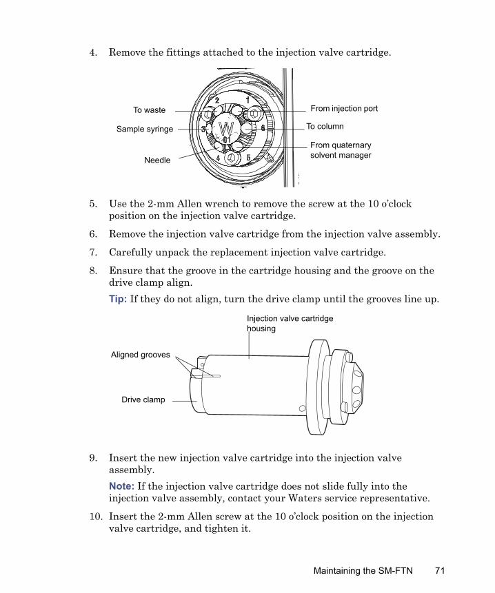
4. Remove the fittings attached to the injection valve cartridge.
5. Use the 2-mm Allen wrench to remove the screw at the 10 o’clock position on the injection valve cartridge.
6. Remove the injection valve cartridge from the injection valve assembly.
7. Carefully unpack the replacement injection valve cartridge.
8. Ensure that the groove in the cartridge housing and the groove on the drive clamp align. Tip: If they do not align, turn the drive clamp until the grooves line up.
9. Insert the new injection valve cartridge into the injection valve assembly.Note: If the injection valve cartridge does not slide fully into the injection valve assembly, contact your Waters service representative.
10. Insert the 2-mm Allen screw at the 10 o’clock position on the injection valve cartridge, and tighten it.
From injection port
To column
From quaternary solvent manager
To waste
Sample syringe
Needle
Drive clamp
Aligned grooves
Injection valve cartridge housing
Maintaining the SM-FTN 71
11. Reattach all fittings, ensuring the tubes bottom in their fitting holes.
12. Ensure the SM-FTN’s door is closed.
13. Power-on the SM-FTN.
Cleaning the instrument’s exteriorClean surfaces of the SM-FTN using only a soft, lint-free paper or cloth dampened with water.Observe these requirements when cleaning device surfaces:
• Always ensure the electrical power to the device is interrupted.• Always use eye and hand protection during the cleaning process.• Apply the water to a clean cloth only, and then wipe the device.• Never spray or apply the water directly onto any device surface.
72