acronyms, formulas & well control forms - home - enform acronyms, formulas and well control...
TRANSCRIPT
AC
RO
NY
MS
, F
OR
MU
LA
S &
WE
LL
CO
NT
RO
L F
OR
MS
Acronyms, Formulas
& Well Control Forms
Acronyms, Formulas and Well Control Forms
i
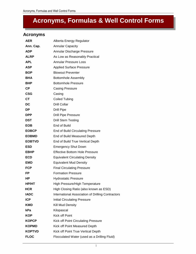
Acronyms
AER Alberta Energy Regulator
Ann. Cap. Annular Capacity
ADP Annular Discharge Pressure
ALRP As Low as Reasonably Practical
APL Annular Pressure Loss
ASP Applied Surface Pressure
BOP Blowout Preventer
BHA Bottomhole Assembly
BHP Bottomhole Pressure
CP Casing Pressure
CSG Casing
CT Coiled Tubing
DC Drill Collar
DP Drill Pipe
DPP Drill Pipe Pressure
DST Drill Stem Testing
EOB End of Build
EOBCP End of Build Circulating Pressure
EOBMD End of Build Measured Depth
EOBTVD End of Build True Vertical Depth
ESD Emergency Shut Down
EBHP Effective Bottom Hole Pressure
ECD Equivalent Circulating Density
EMD Equivalent Mud Density
FCP Final Circulating Pressure
FP Formation Pressure
HP Hydrostatic Pressure
HP/HT High Pressure/High Temperature
HCR High Closing Ratio (also known as ESD)
IADC International Association of Drilling Contractors
ICP Initial Circulating Pressure
KMD Kill Mud Density
kPa Kilopascal
KOP Kick off Point
KOPCP Kick off Point Circulating Pressure
KOPMD Kick off Point Measured Depth
KOPTVD Kick off Point True Vertical Depth
FLOC Flocculated Water (used as a Drilling Fluid)
Acronyms, Formulas & Well Control Forms
Acronyms, Formulas and Well Control Forms
ii
FOSV Fully Opening Safety Valve
LOG Leak-Off Gradient
LOP Leak-Off Pressure
LWD Logging-While-Drilling
MACP Maximum Allowable Casing Pressure
MADFD Maximum Allowable Drilling Fluid Density
MASP Maximum Applied Surface Pressure
MDI Mud Density Increase
MGS Mud Gas Separator
MPD Managed Pressure Drilling
MR Mixing Rate
NMD New Mud Density
OBM Oil-Based Mud
OK Overkill
OMD Original Mud Density
PBD Pump Bore Diameter
PID Proportional-Integral-Derivative
PO Pump Output
PVT Pit Volume Totalizer
PVT Pressure, Volume, and Temperature
PWD Pressure-While-Drilling
RCD Rotating Control Device
RCH Rotating Control Head
RS Reduced Speed
RSPP Reduced Speed Pump Pressure
ROP Rate of Penetration
SAGD Steam Assisted Gravity Drainage
SAPP Sodium Acid Pyrophosphate (thinner/dispersant)
SICP Shut-In Casing Pressure
SIDPP Shut-In Drill Pipe Pressure
SL Stroke Length
SLSWC Second Line Supervisor’s Well Control
SPM Strokes per Minute
SPP Standpipe Pressure
STKS Strokes
TVD True Vertical Depth
TMD Total Measured Depth
UBD Underbalanced Drilling
WBM Water-Based Mud
WC Well Control
WBE Wellbore Barrier Element
WBS Well Barrier Schematics
Acronyms, Formulas and Well Control Forms
iii
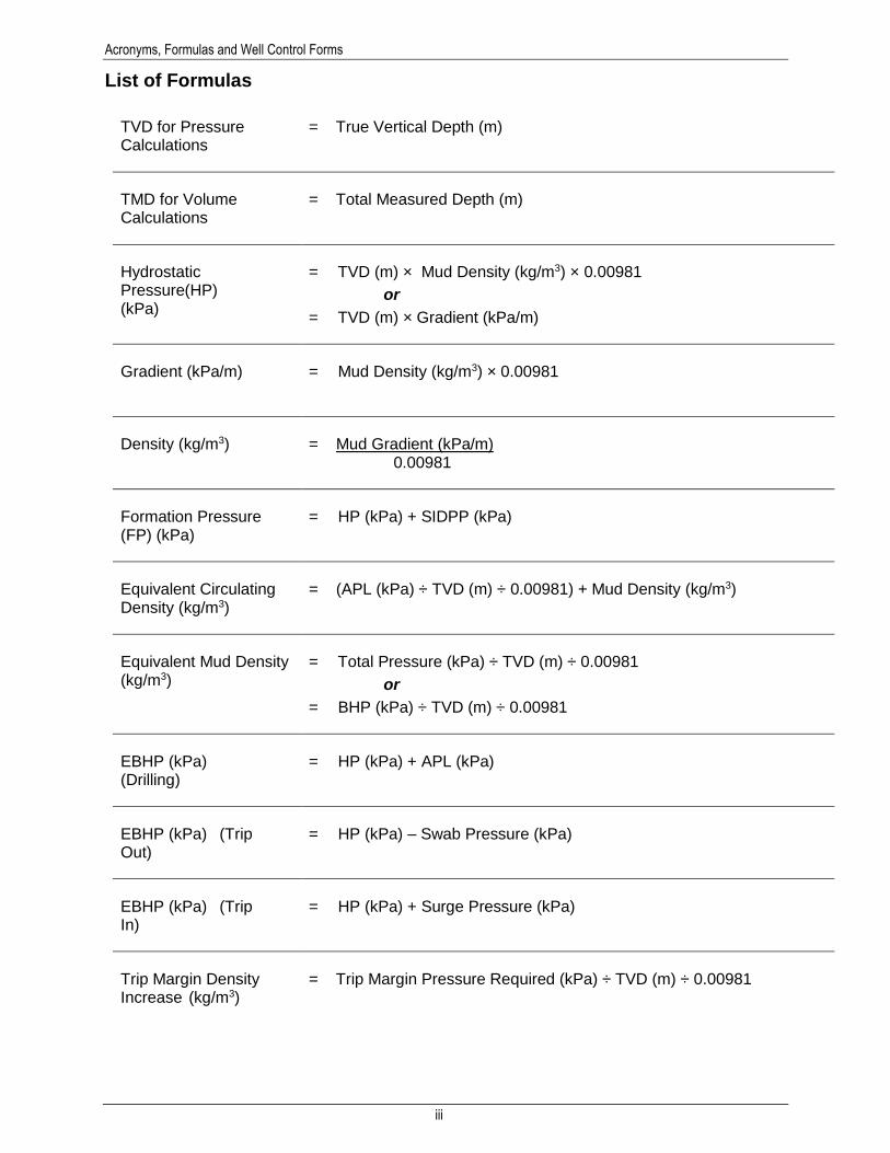
List of Formulas
TVD for Pressure Calculations
= True Vertical Depth (m)
TMD for Volume Calculations
= Total Measured Depth (m)
Hydrostatic Pressure(HP) (kPa)
= TVD (m) × Mud Density (kg/m3) × 0.00981
or
= TVD (m) × Gradient (kPa/m)
Gradient (kPa/m)
= Mud Density (kg/m3) × 0.00981
Density (kg/m3) = Mud Gradient (kPa/m) 0.00981
Formation Pressure (FP) (kPa)
= HP (kPa) + SIDPP (kPa)
Equivalent Circulating Density (kg/m3)
= (APL (kPa) ÷ TVD (m) ÷ 0.00981) + Mud Density (kg/m3)
Equivalent Mud Density (kg/m3)
= Total Pressure (kPa) ÷ TVD (m) ÷ 0.00981
or
= BHP (kPa) ÷ TVD (m) ÷ 0.00981
EBHP (kPa) (Drilling)
= HP (kPa) + APL (kPa)
EBHP (kPa) (Trip Out)
= HP (kPa) – Swab Pressure (kPa)
EBHP (kPa) (Trip In)
= HP (kPa) + Surge Pressure (kPa)
Trip Margin Density Increase (kg/m3)
= Trip Margin Pressure Required (kPa) ÷ TVD (m) ÷ 0.00981
Acronyms, Formulas and Well Control Forms
iv
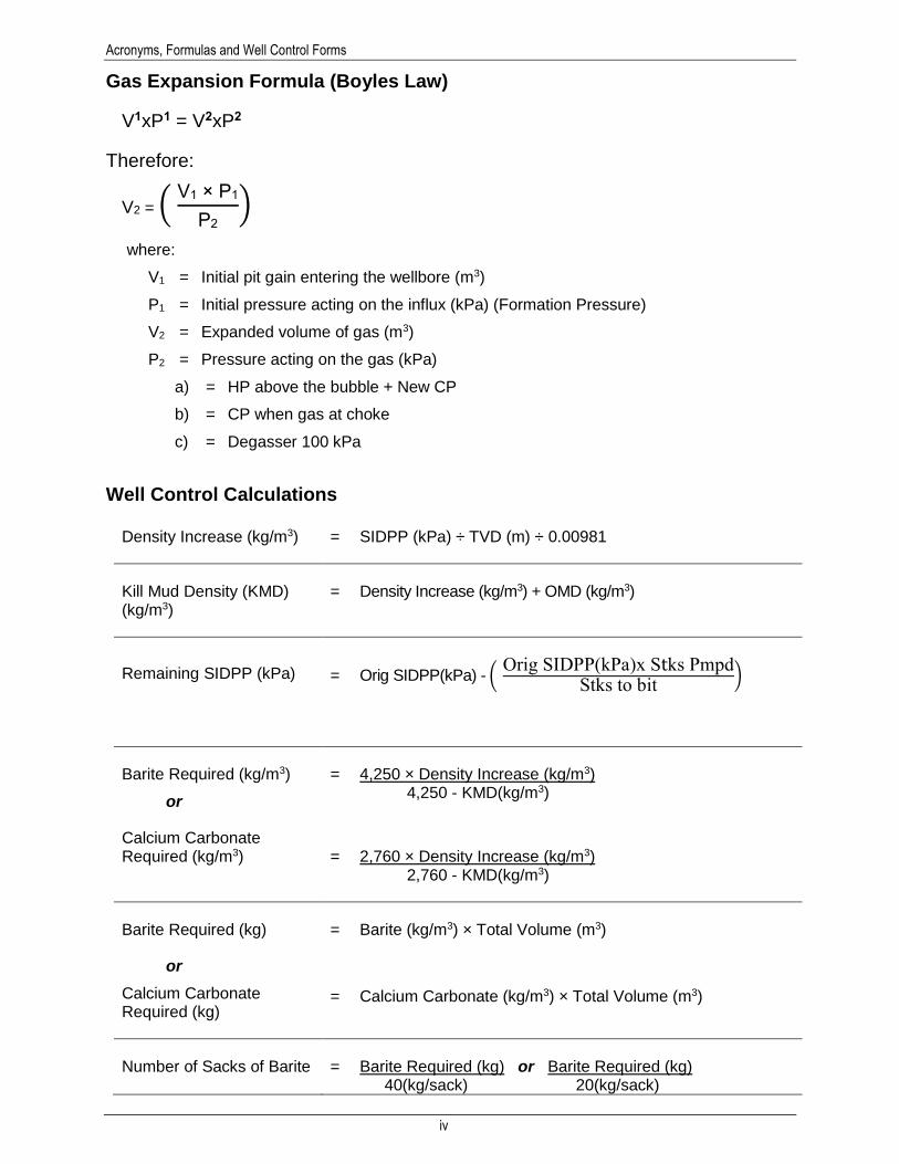
Gas Expansion Formula (Boyles Law)
V1xP1 = V2xP2
Therefore:
V2 = ( V1 × P1
P2)
where:
V1 = Initial pit gain entering the wellbore (m3)
P1 = Initial pressure acting on the influx (kPa) (Formation Pressure)
V2 = Expanded volume of gas (m3)
P2 = Pressure acting on the gas (kPa)
a) = HP above the bubble + New CP
b) = CP when gas at choke
c) = Degasser 100 kPa
Well Control Calculations
Density Increase (kg/m3) = SIDPP (kPa) ÷ TVD (m) ÷ 0.00981
Kill Mud Density (KMD) (kg/m3)
= Density Increase (kg/m3) + OMD (kg/m3)
Remaining SIDPP (kPa) = Orig SIDPP(kPa) - ( Orig SIDPP(kPa)x Stks PmpdStks to bit
)
Barite Required (kg/m3)
or
Calcium Carbonate Required (kg/m3)
= 4,250 × Density Increase (kg/m3) 4,250 - KMD(kg/m3)
= 2,760 × Density Increase (kg/m3) 2,760 - KMD(kg/m3)
Barite Required (kg)
or
Calcium Carbonate Required (kg)
= Barite (kg/m3) × Total Volume (m3)
= Calcium Carbonate (kg/m3) × Total Volume (m3)
Number of Sacks of Barite = Barite Required (kg) or Barite Required (kg) 40(kg/sack) 20(kg/sack)

Acronyms, Formulas and Well Control Forms
v
or
Number of Sacks of Calcium Carbonate
= Calcium Carbonate Required (kg/m3) 25(kg/sack)
(Dependent on sack size delivered to location)
Mixing Rate (MR) (sacks/mi)
= Number of Sacks Reduced Circulating Time (min)
Initial Circulating Pressure (ICP) (kPa)
= RSPP (kPa) + SIDPP (kPa) + Overkill (kPa)
Final Circulating Pressure (FCP) (kPa) = (
RSPP (kPa)× KMD (kg/m3)
OMD (kg/m3)) + Overkill (kPa)
Formulas specific to the Concurrent Method
Density Increase (kg/m3)
= * 40 × Mix Rate × [4,250 – Original Density (kg/m3)] 4,250 × PO (m3/min) + (40 × Mix Rate)
or
= ** 25 × Mix Rate × [2,760 – Original Mud Density (kg/m3)] 2,760 × PO (m3/min) + (25 × Mix Rate)
FCP (kPa)
= ( RSPP (kPa)× NMD (kg/m3)
OMD (kg/m3)) + Remaining SIDPP (kPa)
Remaining SIDPP (kPa)
or
Remaining SIDPP (kPa)
= SIDPP(kPa) – [Density Increase(kg/m3) × Depth(m) × 0.00981]
= TVD (m) × Remaining MDI (kg/m3) × 0.00981
Note: * 40kg/sx (Dependent on sack size delivered to location)
**25kg/sx (Dependent on sack size delivered to location)
Acronyms, Formulas and Well Control Forms
vi
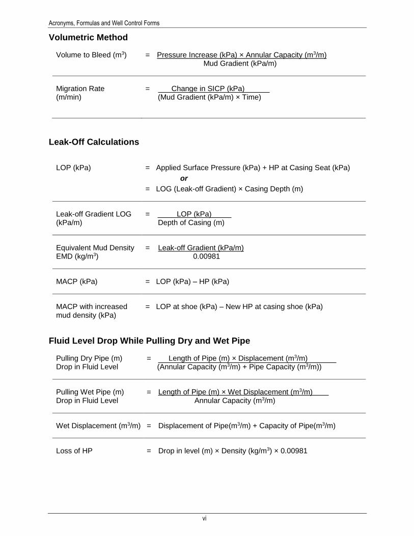
Volumetric Method
Volume to Bleed (m3) = Pressure Increase (kPa) × Annular Capacity (m3/m) Mud Gradient (kPa/m)
Migration Rate (m/min)
= Change in SICP (kPa) (Mud Gradient (kPa/m) × Time)
Leak-Off Calculations
LOP (kPa) = Applied Surface Pressure (kPa) + HP at Casing Seat (kPa)
or
= LOG (Leak-off Gradient) × Casing Depth (m)
Leak-off Gradient LOG (kPa/m)
= LOP (kPa) Depth of Casing (m)
Equivalent Mud Density EMD (kg/m3)
= Leak-off Gradient (kPa/m) 0.00981
MACP (kPa) = LOP (kPa) – HP (kPa)
MACP with increased mud density (kPa)
= LOP at shoe (kPa) – New HP at casing shoe (kPa)
Fluid Level Drop While Pulling Dry and Wet Pipe
Pulling Dry Pipe (m) Drop in Fluid Level
= Length of Pipe (m) × Displacement (m3/m) (Annular Capacity (m3/m) + Pipe Capacity (m3/m))
Pulling Wet Pipe (m) Drop in Fluid Level
= Length of Pipe (m) × Wet Displacement (m3/m) Annular Capacity (m3/m)
Wet Displacement (m3/m) = Displacement of Pipe(m3/m) + Capacity of Pipe(m3/m)
Loss of HP = Drop in level (m) × Density (kg/m3) × 0.00981

Acronyms, Formulas and Well Control Forms
vii
Pill Pumping Calculation
1. Length of Pill (m) = Pill Volume (m3)
Drill Pipe Capacity (m3/m)
2. Differential Pressure (kPa)
= Length of Pill (m) × (Pill Gradient (kPa/m) – Mud Gradient (kPa/m))
3. Empty Pipe Length (m) after pill settles =
Differential Pressure (kPa)
Mud Gradient (kPa/m)
Recovery (m3) = Empty Pipe (m) × Drill Pipe Capacity (m3/m)
or
= Volume of Pill (m3) × ( Pill Density (kg/m3)Mud Density (kg/m3)
-1)
Accumulator Calculations
1. Fluid Required (L) = Litres to Close Annular Preventer + Litres to Close Pipe Ram Preventers + Litres to Open Hydraulic Valve
Critical Sour = Close Annular and Open HCR and Close, Open, Close One Ram and Shear Pipe in Use
2. Total Fluid Required (L) with 50% Safety Margin
= Fluid Required × 1.5
This value is to be used in the Accumulator Size formula below.
Note: Safety margin is established by company policies and manufacturer’s specifications.
3. Accumulator Size (L)
= (Remaining Pressure (kPa) × Total Fluid Required (L)
Pressure on Accumulator (kPa) - Remaining Pressure (kPa)) × (
Pressure on Accumulator (kPa)
Precharge Pressure (kPa))
4. Bottles Required =
Accumulator Size in Litres
Bottle Size (usable fluid)
Nitrogen Backup Calculations
5. Usable Nitrogen/btl (L) = (Bottle Pressure (kPa)
Remaining Pressure (kPa) -1) × Bottle Size (L)
6. Nitrogen Bottles Required =
Fluid Required (without Safety Factor)
Usable Nitrogen/btl (L)
Acronyms, Formulas and Well Control Forms
viii
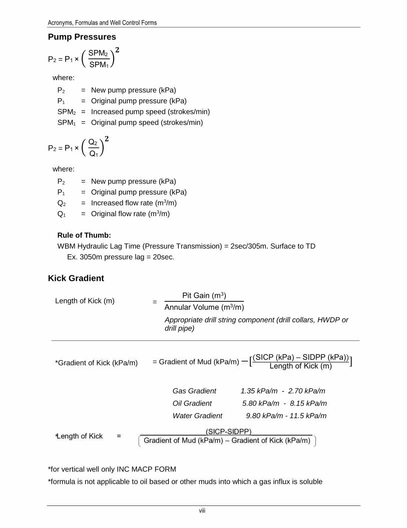
Pump Pressures
P2 = P1 × ( SPM2
SPM1
)𝟐
where:
P2 = New pump pressure (kPa)
P1 = Original pump pressure (kPa)
SPM2 = Increased pump speed (strokes/min)
SPM1 = Original pump speed (strokes/min)
P2 = P1 × ( Q2
Q1
)𝟐
where:
P2 = New pump pressure (kPa)
P1 = Original pump pressure (kPa)
Q2 = Increased flow rate (m3/m)
Q1 = Original flow rate (m3/m)
Rule of Thumb:
WBM Hydraulic Lag Time (Pressure Transmission) = 2sec/305m. Surface to TD
Ex. 3050m pressure lag = 20sec.
Kick Gradient
Length of Kick (m) = Pit Gain (m3)
Annular Volume (m3/m)
Appropriate drill string component (drill collars, HWDP or drill pipe)
*Gradient of Kick (kPa/m)
= Gradient of Mud (kPa/m) −[(SICP (kPa) – SIDPP (kPa))Length of Kick (m)
]
Gas Gradient 1.35 kPa/m - 2.70 kPa/m
Oil Gradient 5.80 kPa/m - 8.15 kPa/m
Water Gradient 9.80 kPa/m - 11.5 kPa/m
*
*for vertical well only INC MACP FORM
*formula is not applicable to oil based or other muds into which a gas influx is soluble
Acronyms, Formulas and Well Control Forms
ix
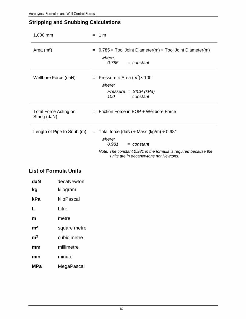
Stripping and Snubbing Calculations
1,000 mm = 1 m
Area (m2) = 0.785 × Tool Joint Diameter(m) × Tool Joint Diameter(m)
where: 0.785 = constant
Wellbore Force (daN) = Pressure × Area (m2)× 100
where:
Pressure = SICP (kPa) 100 = constant
Total Force Acting on String (daN)
= Friction Force in BOP + Wellbore Force
Length of Pipe to Snub (m) = Total force (daN) ÷ Mass (kg/m) ÷ 0.981
where: 0.981 = constant
Note: The constant 0.981 in the formula is required because the units are in decanewtons not Newtons.
List of Formula Units
daN decaNewton
kg kilogram
kPa kiloPascal
L Litre
m metre
m2 square metre
m3 cubic metre
mm millimetre
min minute
MPa MegaPascal

Acronyms, Formulas and Well Control Forms
x
Order of Operations (BEDMAS) BEDMAS is an acronym that reminds us of the correct order of operations:
BEDMAS tells us that brackets are the highest priority, then exponents, then both division and
multiplication, and finally addition and subtraction. This means that we evaluate exponents
before we multiply, divide before we subtract, etc.
Example 1 (Brackets)
15 − (6 + 1) + 30 ÷ (3 × 2)
BEDMAS tells us to evaluate what’s in the brackets first. Therefore, we get the following:
15 − (6 + 1) + 30 ÷ (3 × 2)
= 15 − 7 + 30 ÷ (3 × 2)
= 15 − 7 + 30 ÷ 6
= 15 − 7 + 5
= 8 + 5
= 13
Example 2 (Nested Brackets)
There is no limit on how many sets of brackets we can use in an equation. So you could see an
expression that looks like this:
(8 − (5 + 1) ) × 3
To evaluate an expression like this, we simply follow BEDMAS twice! Once we notice the outer
brackets, we realize that we need to first evaluate the sub-expression they contain using
BEDMAS. Next, we notice the inner-brackets and then we realize that we need to evaluate that
B• Brackets
•First Priority
E• Exponents
•Second Priority
D• Division
•Third Priority
M• Multiplication
•Third Priority
A• Addition
•Fourth Priority
S• Subtraction
•Fourth Priority

Acronyms, Formulas and Well Control Forms
xi
sub-expression first.
A simple rule that summarizes this strategy is:
When dealing with brackets inside brackets (called nested brackets), evaluate
what’s inside the inner-most brackets first.
Remember that this rule is just BEDMAS. It’s nothing new. Using this rule, our sample
expression would be evaluated as follows:
(8 − (5 + 1)) × 3
= (8 − 6) × 3
= 2 x 3
= 6
Example 3 (Exponents)
There are two important rules to remember when dealing with exponents:
1. Any number to the exponent 1 is equal to itself.
2. Any number (except for 0) to the exponent 0 is equal to 1.
25 = 2 × 2 × 2 × 2 × 2 = 32
70 = 1
32 = 3 × 3 = 9
51 = 5
05 = 0
Example 4
8 + 4 × 3 ÷ 2
= 8 + 12 ÷ 2
= 8 + 6
= 14
From BEDMAS, we see that the division and multiplication must be done before the addition.
Acronyms, Formulas and Well Control Forms
xii
Forms The Enform forms presented in the following pages as well as the Check List
are guides to help Prepare, Execute, and Review the Well Control Procedures
in this manual. These forms can be used for all well control methods. They are
available here for your use in the field should you require them. Enform does
not accept any liability whatsoever in there use or resulting outcomes on the
well.
Checklist
Used for Equipment and Data Check on pages Chapter 4-54 to 4-57
Well Control Data Sheets
Used to collect necessary data for well configurations listed below for all methods of well control:
Vertical Hole
Deviated Hole
Vertical Liner
Deviated Liner
Well Control Operations Record Sheet
Used to record all Kill Operations.
Well Control Kill Sheet
Used to calculate all the parameters required to kill the well with a weighted drilling fluid (mud):
Casing: 1st Circulation for Concurrent and Low Choke.
Casing: 2nd Circulation for Driller’s, Wait & Weight, and Concurrent.
Liner: 2nd Circulation for Driller’s, Wait & Weight, and Concurrent.
Deep Liner: Multiple strings DP, HWDP, DC.
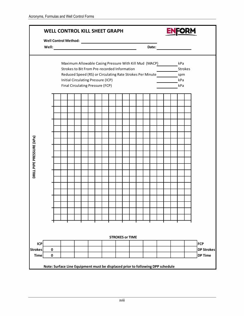
Well Control Kill Sheet Graph
Used to show the change from the Initial Circulating Pressure (ICP) to the Final Circulating Pressure (FCP) as the kill fluid is pumped down the Drill Pipe.
Volumetric Method Kill Sheet
Deviated Horizontal Kill Sheet
A pressure graphs used to show the change from ICP (Initial Circulating Pressure) to KOPCP (Kick off Point Circulating Pressure) to EOBCP (End of Build Circulating Pressure) to FCP (Final Circulating Pressure)

Acronyms, Formulas and Well Control Forms
xiii
Blank Kill Sheet for Well Control
WELL:
MD TVD UNITS
Depth m
Surface casing – Specifications mm
Set at m
Annulus Length (to liner top) m
BOP RATING KPa
Intermediate Casing – Specifications
Top m
Set at m
KICK OFF POINT (KOP) m
END OF BUILD (EOB) m
Hole Size mm
DRILL STRING
Length Specifications Capacity m3/m
Push Pipe
Drill Pipe
Heavy Weight
Drill Collars
ANNULAR CAPACITY
DC to open hole annular capacity m3/m
Tubulars in open hole annular capacity m3/m
Tubulars in casing annular Capacity m3/m
Original Mud Density (OMD) Kg/m3
Leak Off Gradient (LOG) KPa/m
PUMP SPECIFICATIONS
Bore Stroke Reduced Speed
RSPP Displacement
Pump #1
Pump #2
Surface Line Volume * m3
Mud Tank Volume m3
Shut in Drill Pipe Pressure (SIDPP) KPa
Shut In Casing Pressure (SICP) KPa
Pit Gain m3
OverKill (If Used) KPa
* Account for surface line volume when pumping kill mud to the bit. Reset strokes when kill mud reaches floor, then follow drill pipe schedule pumping kill mud to the bit.

Acronyms, Formulas and Well Control Forms
xiv
Well MD m Well TVD m SICP kPa Pump Output m3/stk
Kick Size m3 Shoe TVD m SIDPP KPa Reduced Strokes stks/min
VOLUMES, DISPLACEMENT TIMES AND STROKES – Use Measured Depth (MD)
Length
(m) Capacity (m3/m)
Volume (m3) Strokes Minutes
Strokes to Displace Surface Lines
Surface to KOP or (Surface to BHA if Vertical)
(L)
KOP to EOB (Vertical Well Leave Blank)
(M)
EOB to BHA (Vertical Well Leave Blank)
(N1)
Heavy Weight Drill Pipe (N2)
Drill Collar (N3)
Drill String Volume (Surface to Bit) (D)
DC in Open Hole
Tubulars in Open Hole
Open Hole Volume (Bit to casing Shoe) (E)
Washout (Estimated %) (E) x 10% 10% Open Hole Volume with Washout (Bit to Surface) (F)
Tubulars in Casing (G)
Total Annulus Volume H=F+G (H)
Total Well System Volume (Surface to Surface) I=D+H (I)
Active Surface Volume (J)
Total active Fluid System =I+J
Initial MACP – Use True Vertical Depth at Casing Shoe (TVD)
LOP = Shoe TVD m × Leak off Gradient kPa/m = kPa
HP = Shoe TVD m × Original Mud Density kg/m3 × 0.00981 = kPa
Current MACP = LOP kPa – HP kPa = kPa
Mud Density Increase (MDI) = SIDPP kPa ÷ TVD m ÷ 0.00981 = kg/m3
Kill Mud Density = Original Mud Density kg/m3 + MDI kg/m3 = kg/m3
New MACP with Kill Mud – Use True Vertical Depth (TVD)
New HP = Shoe TVD m × Kill Mud Density kg/m3 × 0.00981 = kPa
New MACP = LOP kPa – New HP kPa = kPa
BARITE REQUIREMENTS
Barite Required = 4250kg/m3 × Density Increase kg/m3
= kg/m3 [4250kg/m3 – Kill Mud Density kg/m3]
Total Barite = Barite required kg/m3 × Total active Fluid System m3 = kg
Number of Sacks = Total Barite kg ÷ 40 kg/sack = Sacks
Mixing Rate (If mixed on the fly) = Number of Sacks ÷ Total Minutes = Sacks/min
(for Concurrent Method Proceed to PG 4)
Acronyms, Formulas and Well Control Forms
xv
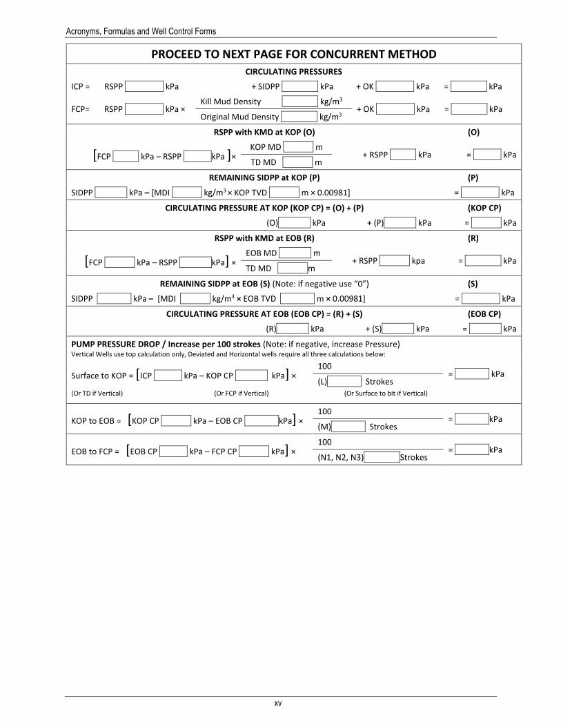
PROCEED TO NEXT PAGE FOR CONCURRENT METHOD
CIRCULATING PRESSURES
ICP = RSPP kPa + SIDPP kPa + OK kPa = kPa
FCP= RSPP kPa × Kill Mud Density kg/m3
+ OK kPa = kPa Original Mud Density kg/m3
RSPP with KMD at KOP (O) (O)
[FCP kPa – RSPP kPa ]× KOP MD m
+ RSPP kPa = kPa TD MD m
REMAINING SIDPP at KOP (P) (P)
SIDPP kPa – [MDI kg/m3 × KOP TVD m × 0.00981] = kPa
CIRCULATING PRESSURE AT KOP (KOP CP) = (O) + (P) (KOP CP)
(O) kPa + (P) kPa = kPa
RSPP with KMD at EOB (R) (R)
[FCP kPa – RSPP kPa] × EOB MD m
+ RSPP kpa = kPa TD MD m
REMAINING SIDPP at EOB (S) (Note: if negative use “0”) (S)
SIDPP kPa – [MDI kg/m3 × EOB TVD m × 0.00981] = kPa
CIRCULATING PRESSURE AT EOB (EOB CP) = (R) + (S) (EOB CP)
(R) kPa + (S) kPa = kPa
PUMP PRESSURE DROP / Increase per 100 strokes (Note: if negative, increase Pressure) Vertical Wells use top calculation only, Deviated and Horizontal wells require all three calculations below:
Surface to KOP = [ICP kPa – KOP CP kPa] × 100
= kPa (L) Strokes
(Or TD if Vertical) (Or FCP if Vertical) (Or Surface to bit if Vertical)
KOP to EOB = [KOP CP kPa – EOB CP kPa] × 100
= kPa (M) Strokes
EOB to FCP = [EOB CP kPa – FCP CP kPa] × 100
= kPa (N1, N2, N3) Strokes
Acronyms, Formulas and Well Control Forms
xvi
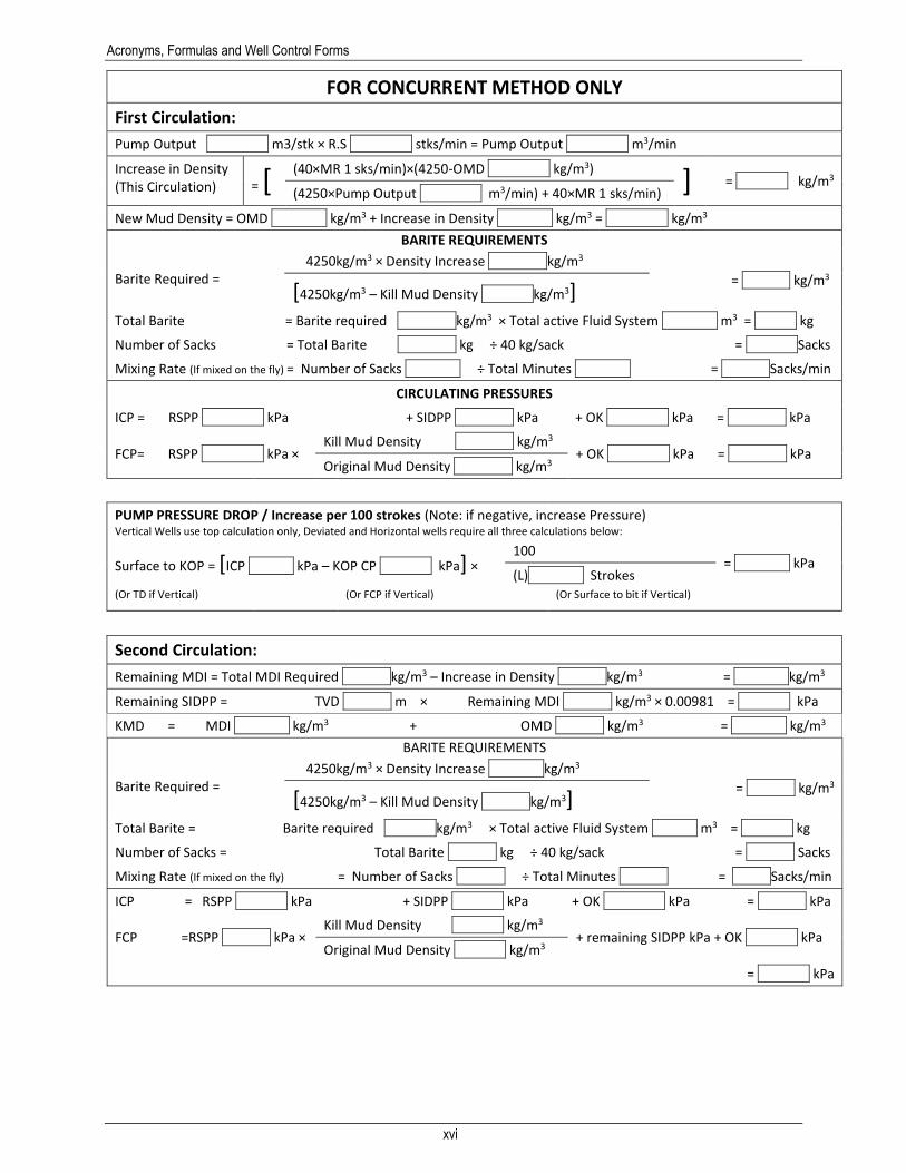
FOR CONCURRENT METHOD ONLY
First Circulation:
Pump Output m3/stk × R.S stks/min = Pump Output m3/min Increase in Density (This Circulation) = [
(40×MR 1 sks/min)×(4250-OMD kg/m3) ] = kg/m3
(4250×Pump Output m3/min) + 40×MR 1 sks/min)
New Mud Density = OMD kg/m3 + Increase in Density kg/m3 = kg/m3
BARITE REQUIREMENTS
Barite Required = 4250kg/m3 × Density Increase kg/m3
= kg/m3 [4250kg/m3 – Kill Mud Density kg/m3]
Total Barite = Barite required kg/m3 × Total active Fluid System m3 = kg
Number of Sacks = Total Barite kg ÷ 40 kg/sack = Sacks
Mixing Rate (If mixed on the fly) = Number of Sacks ÷ Total Minutes = Sacks/min
CIRCULATING PRESSURES
ICP = RSPP kPa + SIDPP kPa + OK kPa = kPa
FCP= RSPP kPa × Kill Mud Density kg/m3
+ OK kPa = kPa Original Mud Density kg/m3
PUMP PRESSURE DROP / Increase per 100 strokes (Note: if negative, increase Pressure) Vertical Wells use top calculation only, Deviated and Horizontal wells require all three calculations below:
Surface to KOP = [ICP kPa – KOP CP kPa] × 100
= kPa (L) Strokes
(Or TD if Vertical) (Or FCP if Vertical) (Or Surface to bit if Vertical)
Second Circulation:
Remaining MDI = Total MDI Required kg/m3 – Increase in Density kg/m3 = kg/m3
Remaining SIDPP = TVD m × Remaining MDI kg/m3 × 0.00981 = kPa
KMD = MDI kg/m3 + OMD kg/m3 = kg/m3
BARITE REQUIREMENTS
Barite Required = 4250kg/m3 × Density Increase kg/m3
= kg/m3 [4250kg/m3 – Kill Mud Density kg/m3]
Total Barite = Barite required kg/m3 × Total active Fluid System m3 = kg
Number of Sacks = Total Barite kg ÷ 40 kg/sack = Sacks
Mixing Rate (If mixed on the fly) = Number of Sacks ÷ Total Minutes = Sacks/min
ICP = RSPP kPa + SIDPP kPa + OK kPa = kPa
FCP =RSPP kPa × Kill Mud Density kg/m3
+ remaining SIDPP kPa + OK kPa Original Mud Density kg/m3
= kPa

Acronyms, Formulas and Well Control Forms
xvii
WELL CONTROL OPERATIONS RECORD SHEET
WELL CONTROL METHOD: _____________________ KICK DATA
Well: ______________________________________ Date: _______________
spm
kPa
kPa
kPa
kPa
kPa
m3
kg/m3
RSPP + kPa
SIDPP + kPa
OK + kPa
Initial Circulating Press. - ICP = kPa
Pump Strokes to Bit stk
Final Circulating Press. - FCP kPa
SICP + kPa
0K + kPa
Initial Kill CP = kPa
SIDPP +
RSPP +
MINIMUM =
____:____ minkPa
- kPa
= kPa
+ kPa
= kPa
____:____ AM/PM
Gas To Surface TimeInitial DPP @ RS
Allowable Increase in MACP
Original MACP
NEW MACP
Lowest DPP @ GTS
Stabilized SICP
M.A.C.P.
Initial Pit Gain
Mud (Drilling Fluid) Density
kPa
kPa
kPa
RECORD CIRCULATING PRESSURES EVERY 2 MINUTES RECORDED KICK DATA
RS Pump Pressure - RSPP
M.A.C.P. Increase - NO WEIGHT MATERIAL ADDED
DPP REQUIRED TO CONTROL FORMATION
INITIAL KILL CASING PRESSURE
CIRCULATING DRILL PIPE PPRESSURES
Reduced Speed - RS
Overkill - OK
Stabilized SIDPP
FINAL SHUT-IN PRESSURESTIMESICP
WELL SHUT-IN @
SIDPP
REMARKS or
PROBLEMS
TIME
(hrs:min)
DPP
(kPa)
CP
(kPa)
TANK
GAIN
(m3)
CHOKE
POSITION
(%)
Acronyms, Formulas and Well Control Forms
xviii
WELL CONTROL KILL SHEET GRAPH
Well Control Method:
Well: Date:
Maximum Allowable Casing Pressure With Kill Mud (MACP) kPa
Strokes to Bit From Pre-recorded Information Strokes
Reduced Speed (RS) or Circulating Rate Strokes Per Minute spm
Initial Circulating Pressure (ICP) kPa
Final Circulating Pressure (FCP) kPa
STROKES or TIME
ICP FCP
Strokes DP Strokes
Time DP Time
Note: Surface Line Equipment must be displaced prior to following DPP schedule
0
DR
ILL
PIP
E P
RES
SUR
E (k
Pa)
0

Acronyms, Formulas and Well Control Forms
xix
WELL CONTROL KILL SHEET - VOLUMETRIC METHOD
Well TVD m Well Name
Well TMD m Casing Depth m Date
Annular Capacity (m3/m) : m
3/m Time :
Pressure Increase (kPa) : kPaStep 7
OverKill (kPa) : kPa Time :
kPa
Mud Density (kg/m3) : kg/m
3 Step 6Bleed : :
Starting Volume (m3) : (Pit Gain) Time :
kPa m3
Cumulative Volume (m3) Time :
Volume to Bleed Off (m3) : (Use Formula Below)
Step 5Bleed : :
Shut In @ (time) : Hours Time :
kPa m3
Cumulative Volume (m3) Time :
S I C P (kPa) : kPaStep 4
Bleed : :
MACP (kPa): kPa Time :
kPa m3
Cumulative Volume (m3) Time :
Step 3Bleed : :
S I C P & TimeTime : Time :
kPa m3
Cumulative Volume (m3) Time :
OVERKILL Step 2Bleed : :
PRESSURE INCREASEkPa m
3Cumulative Volume (m
3) Time :
TOTAL >>> Step 1Bleed : :
Time at First Press Build Up:_____________m
3Cumulative Volume (m
3) Time :
Migration Rate :
Perculation Rate
(meters/minute) =
Mud Gradient (kPa/m)
( Pressure Increase (kPa) x Annular Capacity (m3/m)) ( Mud Gradient (kPa/m) X Time (min) )
Change in SICP (kPa)Volume to Bleed Off (m
3) :
Acronyms, Formulas and Well Control Forms
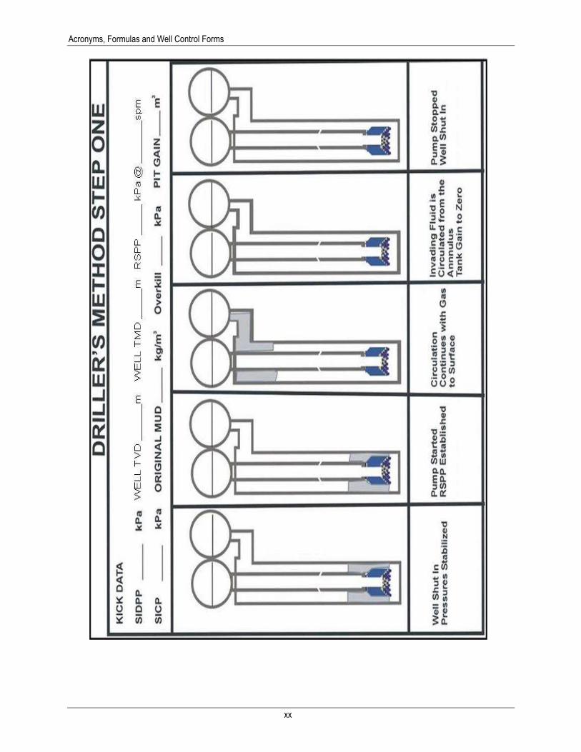
xx
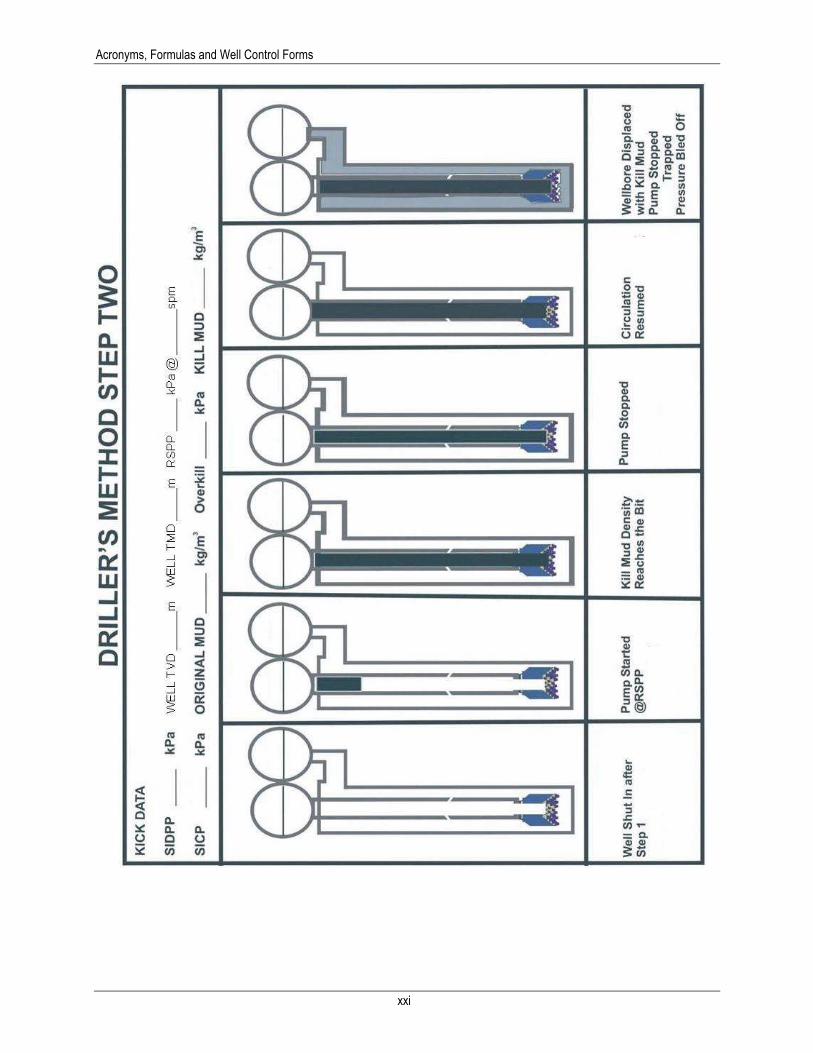
Acronyms, Formulas and Well Control Forms
xxi