acs 502 installation & start-up manual...acs 502 abb drives installation & start-up manual...
TRANSCRIPT

ACS 502
ABB Drives
Installation & Start-up Manual
ASEA BROWN BOVERI
ACS 502/504 Adjustable FrequencyAC Drives 50 to 400 HP, Series B
ACS 502-04FEFFECTIVE 8/31/95SUPERSEDES 9/1/94


1995 ABB Industrial Systems Inc. All Rights Reserved.
ACS 502/504Adjustable Frequency AC Drives
50 to 400 HP, Series B
Installation & Start-up Manual
ACS 502-04F
EFFECTIVE: 1995-08-30SUPERSEDES: 1994-09-01


ACS 502 Installation & Start-up Manual iii
Safety Instructions
General Safety Instructions
Warnings in this manual appear in either of two ways:
• Dangerous voltage warnings, preceded by a Dangerous Voltage symbol, indicate the presence of voltages which may cause death or serious injury. These warnings describe procedures to avoid death or serious injury.
• General warnings, preceded by a General Warning symbol, indicate situations or conditions which may cause death or serious injury. These warnings describe procedures to avoid death or serious injury.
CAUTIONS inform you of situations or conditions which will damage machinery or cause additional motor-operation down-time if you do not take suggested steps to correct or address such situations or conditions.
Note: Notes provide you with additional and useful information. Although less urgent than cautions and warnings, notes are important and should not be ignored.
Warning Symbols For your own safety please pay special attention to instructions containing these symbols:
This warning symbol indicates the presence of dangerous voltage. This symbol informs you of high voltage conditions, situations, and locations that may cause death or serious injury if you do not follow precautions and proper steps.
This warning symbol indicates a general warning.
This warning symbol indicates an electrostatic discharge hazard.

Safety Instructions
iv ACS 502 Installation & Start-up Manual
Warnings, Cautions,and Notes
WARNING! Your drive contains dangerous voltages when connected to the line power. Always check that the ACS 502/504 is safe, after disconnecting the power, by measuring the DC bus voltage and line input voltage. Failure to check voltages could cause death or serious injury. Only a qualified electrician should carry out the electrical installation.
Note that the Motor Control Card of the ACS 502/504 is at DC bus voltage potential.
The DC bus capacitors contain dangerous DC voltage levels (1.35 x VIN). After disconnecting the supply, wait at least five minutes after the display readout on the control panel has disappeared before taking any measurements.
Dangerous external control voltages may be present on the relay outputs of the Control Interface Card and Option Cards.
CAUTION : Electrostatic Discharge (ESD) can damage electronic circuits. Do not handle any components without following the proper ESD precautions.
ACS 502 Installation & Start-up Manual v
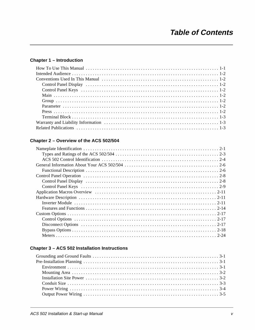
Table of Contents
Chapter 1 – Introduction
How To Use This Manual . . . . . . . . . . . . . . . . . . . . . . . . . . . . . . . . . . . . . . . . . . . . . . . . . . . . . . . . . . 1-1Intended Audience . . . . . . . . . . . . . . . . . . . . . . . . . . . . . . . . . . . . . . . . . . . . . . . . . . . . . . . . . . . . . . . . 1-2Conventions Used In This Manual . . . . . . . . . . . . . . . . . . . . . . . . . . . . . . . . . . . . . . . . . . . . . . . . . . . 1-2
Control Panel Display . . . . . . . . . . . . . . . . . . . . . . . . . . . . . . . . . . . . . . . . . . . . . . . . . . . . . . . . . . 1-2Control Panel Keys . . . . . . . . . . . . . . . . . . . . . . . . . . . . . . . . . . . . . . . . . . . . . . . . . . . . . . . . . . . . 1-2Main . . . . . . . . . . . . . . . . . . . . . . . . . . . . . . . . . . . . . . . . . . . . . . . . . . . . . . . . . . . . . . . . . . . . . . . . 1-2Group . . . . . . . . . . . . . . . . . . . . . . . . . . . . . . . . . . . . . . . . . . . . . . . . . . . . . . . . . . . . . . . . . . . . . . . 1-2Parameter . . . . . . . . . . . . . . . . . . . . . . . . . . . . . . . . . . . . . . . . . . . . . . . . . . . . . . . . . . . . . . . . . . . . 1-2Press . . . . . . . . . . . . . . . . . . . . . . . . . . . . . . . . . . . . . . . . . . . . . . . . . . . . . . . . . . . . . . . . . . . . . . . . 1-2Terminal Block . . . . . . . . . . . . . . . . . . . . . . . . . . . . . . . . . . . . . . . . . . . . . . . . . . . . . . . . . . . . . . . . 1-3
Warranty and Liability Information . . . . . . . . . . . . . . . . . . . . . . . . . . . . . . . . . . . . . . . . . . . . . . . . . . 1-3Related Publications . . . . . . . . . . . . . . . . . . . . . . . . . . . . . . . . . . . . . . . . . . . . . . . . . . . . . . . . . . . . . . 1-3
Chapter 2 – Overview of the ACS 502/504
Nameplate Identification . . . . . . . . . . . . . . . . . . . . . . . . . . . . . . . . . . . . . . . . . . . . . . . . . . . . . . . . . . . 2-1Types and Ratings of the ACS 502/504 . . . . . . . . . . . . . . . . . . . . . . . . . . . . . . . . . . . . . . . . . . . . . 2-3ACS 502 Control Identification . . . . . . . . . . . . . . . . . . . . . . . . . . . . . . . . . . . . . . . . . . . . . . . . . . . 2-4
General Information About Your ACS 502/504 . . . . . . . . . . . . . . . . . . . . . . . . . . . . . . . . . . . . . . . . . 2-6Functional Description . . . . . . . . . . . . . . . . . . . . . . . . . . . . . . . . . . . . . . . . . . . . . . . . . . . . . . . . . . 2-6
Control Panel Operation . . . . . . . . . . . . . . . . . . . . . . . . . . . . . . . . . . . . . . . . . . . . . . . . . . . . . . . . . . . 2-8Control Panel Display . . . . . . . . . . . . . . . . . . . . . . . . . . . . . . . . . . . . . . . . . . . . . . . . . . . . . . . . . . 2-8Control Panel Keys . . . . . . . . . . . . . . . . . . . . . . . . . . . . . . . . . . . . . . . . . . . . . . . . . . . . . . . . . . . . 2-9
Application Macros Overview . . . . . . . . . . . . . . . . . . . . . . . . . . . . . . . . . . . . . . . . . . . . . . . . . . . . . 2-11Hardware Description . . . . . . . . . . . . . . . . . . . . . . . . . . . . . . . . . . . . . . . . . . . . . . . . . . . . . . . . . . . . 2-11
Inverter Module . . . . . . . . . . . . . . . . . . . . . . . . . . . . . . . . . . . . . . . . . . . . . . . . . . . . . . . . . . . . . . 2-11Features and Functions . . . . . . . . . . . . . . . . . . . . . . . . . . . . . . . . . . . . . . . . . . . . . . . . . . . . . . . . . 2-14
Custom Options . . . . . . . . . . . . . . . . . . . . . . . . . . . . . . . . . . . . . . . . . . . . . . . . . . . . . . . . . . . . . . . . . 2-17Control Options . . . . . . . . . . . . . . . . . . . . . . . . . . . . . . . . . . . . . . . . . . . . . . . . . . . . . . . . . . . . . . 2-17Disconnect Options . . . . . . . . . . . . . . . . . . . . . . . . . . . . . . . . . . . . . . . . . . . . . . . . . . . . . . . . . . . 2-17Bypass Options . . . . . . . . . . . . . . . . . . . . . . . . . . . . . . . . . . . . . . . . . . . . . . . . . . . . . . . . . . . . . . . 2-18Meters . . . . . . . . . . . . . . . . . . . . . . . . . . . . . . . . . . . . . . . . . . . . . . . . . . . . . . . . . . . . . . . . . . . . . . 2-24
Chapter 3 – ACS 502 Installation Instructions
Grounding and Ground Faults . . . . . . . . . . . . . . . . . . . . . . . . . . . . . . . . . . . . . . . . . . . . . . . . . . . . . . . 3-1Pre-Installation Planning . . . . . . . . . . . . . . . . . . . . . . . . . . . . . . . . . . . . . . . . . . . . . . . . . . . . . . . . . . . 3-1
Environment . . . . . . . . . . . . . . . . . . . . . . . . . . . . . . . . . . . . . . . . . . . . . . . . . . . . . . . . . . . . . . . . . . 3-1Mounting Area . . . . . . . . . . . . . . . . . . . . . . . . . . . . . . . . . . . . . . . . . . . . . . . . . . . . . . . . . . . . . . . . 3-2Installation Site Power . . . . . . . . . . . . . . . . . . . . . . . . . . . . . . . . . . . . . . . . . . . . . . . . . . . . . . . . . . 3-2Conduit Size . . . . . . . . . . . . . . . . . . . . . . . . . . . . . . . . . . . . . . . . . . . . . . . . . . . . . . . . . . . . . . . . . . 3-3Power Wiring . . . . . . . . . . . . . . . . . . . . . . . . . . . . . . . . . . . . . . . . . . . . . . . . . . . . . . . . . . . . . . . . . 3-4Output Power Wiring . . . . . . . . . . . . . . . . . . . . . . . . . . . . . . . . . . . . . . . . . . . . . . . . . . . . . . . . . . . 3-5

Table of Contents
vi ACS 502 Installation & Start-up Manual
Power Connections . . . . . . . . . . . . . . . . . . . . . . . . . . . . . . . . . . . . . . . . . . . . . . . . . . . . . . . . . . . . . . . 3-6Input Wiring . . . . . . . . . . . . . . . . . . . . . . . . . . . . . . . . . . . . . . . . . . . . . . . . . . . . . . . . . . . . . . . . . . 3-6Output Wiring . . . . . . . . . . . . . . . . . . . . . . . . . . . . . . . . . . . . . . . . . . . . . . . . . . . . . . . . . . . . . . . . . 3-7Dynamic Braking . . . . . . . . . . . . . . . . . . . . . . . . . . . . . . . . . . . . . . . . . . . . . . . . . . . . . . . . . . . . . . 3-8
Control Connections . . . . . . . . . . . . . . . . . . . . . . . . . . . . . . . . . . . . . . . . . . . . . . . . . . . . . . . . . . . . . . 3-8Available Control Locations . . . . . . . . . . . . . . . . . . . . . . . . . . . . . . . . . . . . . . . . . . . . . . . . . . . . . . 3-8Terminal Block Connections . . . . . . . . . . . . . . . . . . . . . . . . . . . . . . . . . . . . . . . . . . . . . . . . . . . . . 3-9
Chapter 4 – ACS 504 Installation Instructions
Pre-Installation Planning . . . . . . . . . . . . . . . . . . . . . . . . . . . . . . . . . . . . . . . . . . . . . . . . . . . . . . . . . . . 4-1Environment . . . . . . . . . . . . . . . . . . . . . . . . . . . . . . . . . . . . . . . . . . . . . . . . . . . . . . . . . . . . . . . . . . . . . 4-7
Inverter Modules . . . . . . . . . . . . . . . . . . . . . . . . . . . . . . . . . . . . . . . . . . . . . . . . . . . . . . . . . . . . . . . 4-7Control Unit . . . . . . . . . . . . . . . . . . . . . . . . . . . . . . . . . . . . . . . . . . . . . . . . . . . . . . . . . . . . . . . . . . 4-8
Power Wiring . . . . . . . . . . . . . . . . . . . . . . . . . . . . . . . . . . . . . . . . . . . . . . . . . . . . . . . . . . . . . . . . . . . . 4-9Input and Output Power Wiring . . . . . . . . . . . . . . . . . . . . . . . . . . . . . . . . . . . . . . . . . . . . . . . . . . . 4-9Checking the Motor Insulation . . . . . . . . . . . . . . . . . . . . . . . . . . . . . . . . . . . . . . . . . . . . . . . . . . . 4-13
Control Connections . . . . . . . . . . . . . . . . . . . . . . . . . . . . . . . . . . . . . . . . . . . . . . . . . . . . . . . . . . . . . 4-13Available Control Locations . . . . . . . . . . . . . . . . . . . . . . . . . . . . . . . . . . . . . . . . . . . . . . . . . . . . . 4-13X50 . . . . . . . . . . . . . . . . . . . . . . . . . . . . . . . . . . . . . . . . . . . . . . . . . . . . . . . . . . . . . . . . . . . . . . . . 4-14
Control Interface Card Connections . . . . . . . . . . . . . . . . . . . . . . . . . . . . . . . . . . . . . . . . . . . . . . . . . 4-16
Chapter 5 – Start-up Procedure
Safety Precautions . . . . . . . . . . . . . . . . . . . . . . . . . . . . . . . . . . . . . . . . . . . . . . . . . . . . . . . . . . . . . . . . 5-1Installation Inspection . . . . . . . . . . . . . . . . . . . . . . . . . . . . . . . . . . . . . . . . . . . . . . . . . . . . . . . . . . . . . 5-2Start-up Data Parameters . . . . . . . . . . . . . . . . . . . . . . . . . . . . . . . . . . . . . . . . . . . . . . . . . . . . . . . . . . . 5-3Keypad Control Tests . . . . . . . . . . . . . . . . . . . . . . . . . . . . . . . . . . . . . . . . . . . . . . . . . . . . . . . . . . . . . 5-4
Motor Disconnected from the ACS 502 . . . . . . . . . . . . . . . . . . . . . . . . . . . . . . . . . . . . . . . . . . . . . 5-4Motor Connected to the ACS 502 . . . . . . . . . . . . . . . . . . . . . . . . . . . . . . . . . . . . . . . . . . . . . . . . . 5-5Keypad Control vs. External Control . . . . . . . . . . . . . . . . . . . . . . . . . . . . . . . . . . . . . . . . . . . . . . . 5-6
Default Drive Parameters . . . . . . . . . . . . . . . . . . . . . . . . . . . . . . . . . . . . . . . . . . . . . . . . . . . . . . . . . . . 5-7Customizing Application Macro Parameters . . . . . . . . . . . . . . . . . . . . . . . . . . . . . . . . . . . . . . . . . . . . 5-7Password Protection (Parameter Lock) . . . . . . . . . . . . . . . . . . . . . . . . . . . . . . . . . . . . . . . . . . . . . . . . 5-8
Chapter 6 – Fault Tracing
Warning and Fault Messages . . . . . . . . . . . . . . . . . . . . . . . . . . . . . . . . . . . . . . . . . . . . . . . . . . . . . . . . 6-1Warning messages of ACS 502/504 . . . . . . . . . . . . . . . . . . . . . . . . . . . . . . . . . . . . . . . . . . . . . . . . 6-1Fault messages of ACS 502/504 . . . . . . . . . . . . . . . . . . . . . . . . . . . . . . . . . . . . . . . . . . . . . . . . . . . 6-2
Appendix A – ACS 502/504 Technical Data
Input Power . . . . . . . . . . . . . . . . . . . . . . . . . . . . . . . . . . . . . . . . . . . . . . . . . . . . . . . . . . . . . . . . . . . . A-1Output Power . . . . . . . . . . . . . . . . . . . . . . . . . . . . . . . . . . . . . . . . . . . . . . . . . . . . . . . . . . . . . . . . . . . A-1Analog Inputs . . . . . . . . . . . . . . . . . . . . . . . . . . . . . . . . . . . . . . . . . . . . . . . . . . . . . . . . . . . . . . . . . . . A-1Auxiliary Voltage (for Controls) . . . . . . . . . . . . . . . . . . . . . . . . . . . . . . . . . . . . . . . . . . . . . . . . . . . . A-2Digital Inputs . . . . . . . . . . . . . . . . . . . . . . . . . . . . . . . . . . . . . . . . . . . . . . . . . . . . . . . . . . . . . . . . . . . A-2Analog Outputs . . . . . . . . . . . . . . . . . . . . . . . . . . . . . . . . . . . . . . . . . . . . . . . . . . . . . . . . . . . . . . . . . A-2

Table of Contents
ACS 502 Installation & Start-up Manual vii
Digital Relay Outputs . . . . . . . . . . . . . . . . . . . . . . . . . . . . . . . . . . . . . . . . . . . . . . . . . . . . . . . . . . . . .A-2Environmental Limits . . . . . . . . . . . . . . . . . . . . . . . . . . . . . . . . . . . . . . . . . . . . . . . . . . . . . . . . . . . . .A-2Enclosures . . . . . . . . . . . . . . . . . . . . . . . . . . . . . . . . . . . . . . . . . . . . . . . . . . . . . . . . . . . . . . . . . . . . . .A-2
Glossary . . . . . . . . . . . . . . . . . . . . . . . . . . . . . . . . . . . . . . . . . . . . . . . . . . . . . . . . . . . . . . . . . G-1
Index . . . . . . . . . . . . . . . . . . . . . . . . . . . . . . . . . . . . . . . . . . . . . . . . . . . . . . . . . . . . . . . . . . . . . I-1

Table of Contents
viii ACS 502 Installation & Start-up Manual
This page intentionally left blank.

ACS 502 Installation & Start-up Manual 1-1
Chapter 1 – Introduction
This chapter describes the purpose and contents of this manual, describes the intended audience, explains conventions used in this manual, and lists related publications.
How To Use This Manual
The purpose of this manual is to provide you with the information necessary to install, start-up, and service an ACS 502/504 Adjustable Frequency AC Drive rated 50 to 400 hp. This manual also describes features and functions of the drives and requirements such as external drive control connections, wiring, and cable sizes and routing.
ACS 502/504 user documentation also includes the ACS 500 Adjustable Frequency AC Drives 2 to 400 HP Programming Manual Including Application Macros which is provided with the drive.
Chapter 1 – Introduction, the chapter you are reading now, introduces you to the ACS 502/504 Adjustable Frequency AC Drives 50 to 400 HP Installation & Start-up Manual and conventions used throughout the manual.
Chapter 2 – Overview of the ACS 502/504 describes drive components and provides a brief introduction to Control Panel operation, the drive parameter menu system, and drive Application macros.
Chapter 3 – ACS 502 Installation Instructions describes planning for ACS 502 drive installation, new drive inspection, and drive installation. This chapter also includes requirements and connections for input and output wiring and external control wiring.
Chapter 4 – ACS 504 Installation Instructions describes planning for ACS 504 chassis installation, new drive inspection, and drive installation. This chapter also includes requirements and connections for input and output wiring and external control wiring.
Chapter 5 – Start–up Procedure describes safety, installation inspection, how to check default parameters and set start-up parameters, and how to test the drive with the motor disconnected and connected.
Chapter 6 – Fault Tracing describes troubleshooting procedures through fault messages, resetting faults, accessing stored information in the fault history, and tracing faults to their origins.
Appendix A – ACS 502/504 Technical Data lists input and output voltages, amperage, and other useful data for each drive rated 50 to 400 hp.
Glossary lists and defines terms common to all ACS 502/504 drives.
Index helps you locate the page numbers of topics contained in this manual.

Chapter 1 – Introduction
1-2 ACS 502 Installation & Start-up Manual
Intended Audience The audience for this manual has:
• Knowledge of standard electrical wiring practices, electronic components, and electrical schematic symbols.
• Minimal knowledge of ABB product names and terminology.
• No experience or training in installing, operating, or servicing the ACS 502/504.
The audience for this manual will install, start-up, and service the ACS 502/504.
Conventions Used In This Manual
Listed below are terms and language conventions used in this manual. These terms and conventions are defined here to help you understand their meanings and applications throughout this manual. For a complete listing of ACS 502/504 terms, refer to the Glossary at the end of this manual.
Control Panel Display The Control Panel display is an LCD readout of drive functions, drive parameter selections, and other drive information. Letters or numbers appear in the display according to which Control Panel keys you press.
Control Panel Keys Control Panel keys are flat, labeled, push-button-type devices that allow you to monitor drive functions, select drive parameters, and change drive macros and settings.
Main A main is the first level of programming. The Mains organize the Parameters into four main functional groups. A Main in this manual is the number corresponding to Group access. All Groups in the 10s range are accessed on the Control Panel through CONTROL CONNECTIONS/MAIN 10. Access Groups in the 20s range through DRIVE PARAMETERS/MAIN 20. Access Groups in the 30s range through PROTECTION PARAMETER/MAIN 30, and access Groups in the 40’s range through APPLIC PARAMETERS/MAIN 40 .
Group A Group is a sub-set of a Main. Groups are grouped within Mains according to their 10s, 20s, 30s, or 40s range. For example, Groups numbered 30.1, 30.2, 30.3, and 30.4 are found in PROTECTION PARAMETER/MAIN 30. Parameters are accessed through Groups.
Parameter A parameter is a sub-set of a Group, selected through the Control Panel keys. Parameters in this manual often are expressed as a number, a decimal (.), another number, a decimal, and another number. The first number at the left represents the Main. The number between the decimals represents the Group, for example, 20.2 (Start/Stop). The number at the right represents a Parameter within that group, for example, 4 (Brake Chopper). In this manual, Parameter 4 in Group 20.2 is expressed as Parameter 20.2.4.
Press Press a key on the Control Panel to achieve a desired result. In this manual, individual Control Panel keys are enclosed in square brackets. For example, the Setting mode key is expressed as [ * ]. Refer to Chapter 2 – Overview of the ACS 502/504, Control Panel Operation, for details.

Chapter 1 – Introduction
ACS 502 Installation & Start-up Manual 1-3
Terminal Block A terminal block is a group of wire connections on a drive. This manual expresses specific terminal blocks and connections as a letter, usually X, a number, a colon (:), and another number. The letter and number to the left of the colon represent the name of the terminal block, for example, X25. The number to the right of the colon represents the terminal connection, for example 16, on the terminal block. In this manual, a terminal connection numbered 16, located on a terminal block named X25, is expressed as X25:16.
Warranty and Liability Information
The warranty for your ABB drive covers manufacturing defects. The manufacturer carries no responsibility for damage due to transport or unpacking.
In no event and under no circumstances shall the manufacturer be liable for damages and failures due to misuse, abuse, improper installation, or abnormal conditions of temperature, dust, or corrosives, or failures due to operation above rated capacities. Nor shall the manufacturer ever be liable for consequential and incidental damages.
The period of manufacturer's warranty is 12 months, and not more than 18 months, from the date of delivery.
Extended warranty may be available with certified start-up. Contact your local distributor for details.
Your local ABB Drives company or distributor may have a different warranty period, which is specified in their sales terms, conditions, and warranty terms.
If you have any questions concerning your ABB drive, contact your local distributor or ABB Drives office.
The technical data and specifications are valid at the time of printing. ABB reserves the right to subsequent alterations.
Related Publications For related information, refer to the ABB ACS 500 Adjustable Frequency AC Drives 2 to 400 HP Programming Manual Including Application Macros (ACS 500-05).

Chapter 1 – Introduction
1-4 ACS 502 Installation & Start-up Manual
This page intentionally left blank.
ACS 502 Installation & Start-up Manual 2-1
Chapter 2 – Overview of the ACS 502/504
The ACS 502 and ACS 504 are adjustable frequency AC drives for 50 to 300 hp constant torque and 60 to 400 hp variable torque, 480 volt applications; and 60 to 150 hp constant torque and 75 to 200 hp variable torque, 600 volt applications. The ACS 504 is an open chassis, designed for mounting into a customer’s enclosure. The ACS 502 is a complete enclosed assembly (including the ACS 504 module) ready for operation.
This chapter describes the features and functions of the ACS 502, and includes illustrations and block diagrams. It also describes the ACS 502 hardware components and the Control Panel displays and keys. This chapter also presents an overview of the Parameters menu system and Application macros.
Nameplate Identification
Figure 2-1 explains the base drive part number used to derive the drive code printed on the nameplate, located at on the right side of the enclosure, or inside the door of the ACS 502, or on the left side below the brake terminals on the ACS 504.

Chapter 2 – Overview of the ACS 502/504
2-2 ACS 502 Installation & Start-up Manual
Figure 2-1 Explanation of ACS 502/504 Drive Code
ACS 502 - 075 - 4 - 0 0 P 2AC = AC Drive
Product Type:S = Standard Product
Family:50 = ACS 500
Construction1 = Sizes 002 to 060, Wall Mounted2 = Sizes 050 to 350, Std Floor Stand Cabinet4 = Sizes 050 to 350, Module
Output Power (HP, Constant Torque)
Input Voltage3 = 380-415 VAC4 = 440-500 VAC
Internal Option 20 = No Option
Internal Option 12 = I/O Extension Board (SNAT 7520 IOE)8 = (5) Isolated Digital Inputs (SNAT 763 DII)9 = 3-15 PSI and (2) Isolated Digital Inputs (SNAT 762 PSI)
0 = No Option
Control PanelP = Internal Control Panel (Keypad and Display)0 = No Panel
Protection Class of Enclosure*0 = Chassis (IP 00)2 = NEMA 1 (IP 21)3 = NEMA 1 w/Air Filters5 = NEMA 12 (IP 54)
*Not all Protection Classes are available for all units.
A = 115 VAC Control Power Board
Dynamic BrakingBlanks = No Brake1 = Internal Dynamic Brake Chopper Installed
(KVA, Constant Torque for 380 VAC)
6 = 525-600 VAC
3 = Tachometer input option (SNAT 7610 BAC)

Chapter 2 – Overview of the ACS 502/504
ACS 502 Installation & Start-up Manual 2-3
Types and Ratings ofthe ACS 502/504
Table 2-1 shows the type series and ratings of the ACS 504.
Table 2-1 Rating Table for ACS 502 and ACS 504, 440 – 500 VAC,& 525 – 600 VAC
Drive Type
Constant Torque Variable Torque
I NDimension Reference
hp
Amps(Current Rating
of Drive) hp
Amps(Current Rating
of Drive)
I R I IN IRSQ I INSQ
480 volt units
ACS50X-050-4- 50 65 62 60 77 69 65
R6ACS50X-060-4- 60 77 71 75 96 87 84
ACS50X-075-4- 75 96 87 100 124 111 112
ACS50X-100-4- 100 124 113 125 156 141 135R7
ACS50X-125-4- 125 156 143 150 180 159 164
ACS50X-150-4- 150 180 161 200 240 214 200R8
ACS50X-200-4- 200 240 218 250 302 269 240
ACS50X-250-4- 250 302 273 300 361 328 300
R9ACS50X-300-4- 300 361 333 350 414 376 365
ACS50X-350-4- 300 361 333 400 460 418 365
600 volt units
ACS50X-060-6- 60 62 54 75 77 67 77R6
ACS50X-075-6- 75 77 67 100 99 87 77
ACS50X-100-6- 100 99 87 125 125 110 99 R7
ACS50X-125-6- 125 125 110 150 144 126 125 R8
ACS50X-150-6- 150 144 126 200 192 168 172 R9

Chapter 2 – Overview of the ACS 502/504
2-4 ACS 502 Installation & Start-up Manual
Table 2-2 shows the definitions for symbols used in this manual.
Table 2-2 Symbol Definitions
ACS 502 ControlIdentification
The numbers and letters in the last seven spaces of the ACS 502 Model Number stand for the specific options included with your drive. Locate the Control Nameplate on the right side of the enclosure or inside the door of the ACS 502 and use Figure 2-2 to verify the options included with your drive. The first part of the part number is derived from Figure 2-1 by removing the letters AC in the first two places and the dashes (-).
Symbol Definition
VIN Rated supply voltage [V]. The actual voltage is set by a parameter.
IIN Approximate input current (rms) when shaft power is PR, line voltage is 480 V, and the motor is a standard NEMA motor [Amps].
IR Rated output current in constant torque applications [Amps].
PR Maximum motor nominal shaft power in constant torque applications for 2-, 4-, and 6-pole standard motors [hp].
IINSQ Approximate input current when shaft power is PRSQ, line voltage is 480 V and the motor is a standard NEMA motor. This is the maximum thermal input current [Amps].
IRSQ Rated output current in squared torque applications [Amps].
PRSQ Maximum motor nominal shaft power in squared torque applications for 2-, 4-, and 6-pole standard motors [hp].
IN The output current on which the drive’s internal trips and settings are based [Amps].

Chapter 2 – Overview of the ACS 502/504
ACS 502 Installation & Start-up Manual 2-5
Figure 2-2 Nameplate Codes
MOLACS 502A=29.3 to 32.0B=32.1 to 34.9C=35.0 to 37.8D=37.9 to 41.7E=41.8 to 45.9F=46.0 to 49.0G=49.1 to 54.2H=54.3 to 60.0J=57.1 to 62.8K=62.9 to 69.1L=69.2 to 75.0M=75.1 to 83.3N=83.4 to 86.9P=87.0 to 92.9Q=93.0 to 100R=98 to 107.9S=108 to 113.9T=114 to 125.9U=126 to 138.9V=139 to 153W=154 to 163X=164 to 180Y=175 to 194Z=195 to 2202=221 to 2473=248 to 2764=277 to 3075=308 to 3456=346 to 3817=382 to 4208=421 to 4650=None
ACS502-075-4-00P2S502075400P2
NEMA Type Enclosure2=NEMA 13=NEMA 1 with Air Filters5=NEMA 12
ControlA=Hand-Off-Auto Switch incl. 115 V
Control TransformerB=Hand-Off-Auto Switch & Speed Pot
incl. 115 V Control TransformerC=115 VAC Control Transformer
& Terminal Board1=Internal Brake ChopperM=A+1N=B+1P=C+10=None
Input OptionsA=Door Interlocked Disconnect SwitchB=Door Interlocked Circuit BreakerC=Disconnect w/3% Line ReactorD=Circuit Breaker w/3% Line ReactorE=Input Terminal Block w/3% Line
ReactorF=Disconnect w/5% Line ReactorG=Circuit Breaker w/5% Line ReactorH=Input Terminal Block w/5% Line
Reactor0=Extended Enclosure w/Input
Terminal Block
BypassA=Manual BypassB=Manual Bypass w/Service SwitchC=Automatic BypassD=Automatic Bypass w/Service SwitchE=Manual Bypass, Mechanically
InterlockedF=Manual Bypass w/Service Switch,
Mechanically InterlockedG=Automatic Bypass, Mechanically
InterlockedH=Automatic Bypass w/Service
Switch, Mechanically Interlocked0=None
MetersA=Analog VoltmeterB=Analog Speed MeterY=Ammeter (Sized to unit)Z=Two Ammeters (Sized to MOL’s)1=A+B2=A+Y3=A+Z4=B+Y5=B+Z6=A+B+Y7=A+B+Z0=None
* Horsepowers listed are estimated only. MOL’s MUST be sized for the specific motor.
25
30
40
50
60
75
100
125150
200
250
300350
HP*

Chapter 2 – Overview of the ACS 502/504
2-6 ACS 502 Installation & Start-up Manual
General Information About Your ACS 502/504
Functional DescriptionPower-on sequence When line voltage is switched on, the capacitor bank is charged first via the
charging circuit. The charging takes less than one second. During this time, the thyristors on the rectifier bridge are not conducting.
GENERAL WARNING! The maximum permissible number of chargings in one minute is four. If the DC bus is charged more often, the charging resistor may fail due to excess heat. Therefore, it is recommended that you do not use the input power switching on and off as a Start/Stop command.
The power supply of the ACS 504 comes from the capacitor bank. The power supply turns on when the voltage on the capacitors has reached about 300 VDC. Subsequently, the Control Interface Card, Motor Control Card and Main Circuit Interface Card are energized.
When the DC-voltage has reached 80% of its nominal value, the microprocessor on the Motor Control Card energizes the Input Protection Card. The thyristors are gated fully conducting and the thyristor-diode rectifier behaves like a normal 6-pulse diode bridge.
The cooling fan turns on at initial power-on. To prolong the useful life of the fan bearings, the fan is automatically turned off after one minute, unless:
• The drive has a RUN command, or
• Heatsink temperature is above 113°F (45°C).
Control In normal duty the drive follows commands and references either from the keypad or the terminal block on the Control Interface Card. The control signal source selection and the way the drive interprets these signals are configured by parameters.
Power section Power flow through the drive in normal duty is from AC-input line through the rectifier bridge to the DC-filter capacitors which sustain a constant DC-voltage. The nominal value for this voltage is 1.35 x VIN.
The Inverter consists of six power semiconductor switches whose operation is controlled by the Motor Control Card via the Main Circuit Interface Card. Turning these switches on and off in a certain sequence is called modulation. The modulation frequency in the ACS 504 is about 3 kHz at maximum and cannot be altered.
The potential at any terminal U2, V2, W2 (T1, T2, T3) of the inverter can only be high or low. The modulation determines which one. At any instant, the line to line output voltage is either 0 V when the switches in these phases are in the same position or ± 1.35 x VIN when the corresponding switches are in different positions.
Chapter 2 – Overview of the ACS 502/504
ACS 502 Installation & Start-up Manual 2-7
The output voltage waveform is a pulse-train. The widths of the pulses depend on the modulation. The purpose of the modulation is to create the fundamental voltage wave (its amplitude and frequency), e.g., according to the law Vout / fout = constant (V/Hz).
The distortion of the output voltage from the sinusoidal fundamental creates corresponding harmonics in the motor current. However, since the motor is highly inductive and the modulation frequency is relatively high, the current waveform is nearly sinusoidal.
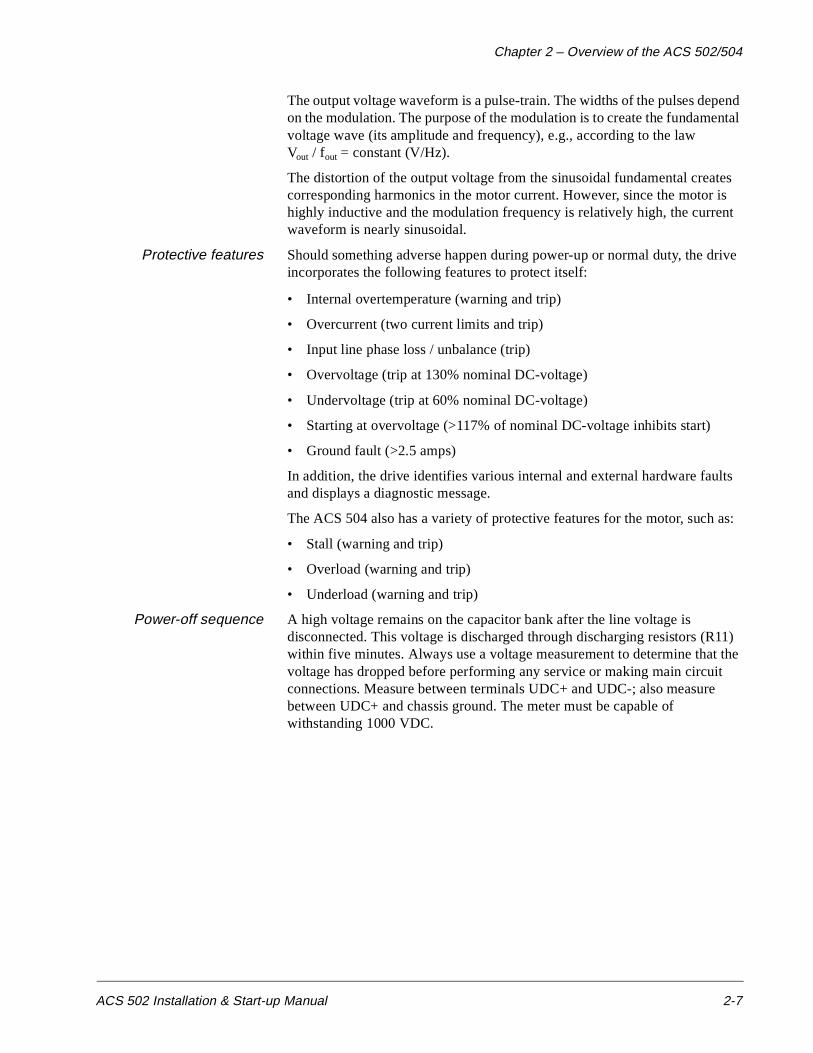
Protective features Should something adverse happen during power-up or normal duty, the drive incorporates the following features to protect itself:
• Internal overtemperature (warning and trip)
• Overcurrent (two current limits and trip)
• Input line phase loss / unbalance (trip)
• Overvoltage (trip at 130% nominal DC-voltage)
• Undervoltage (trip at 60% nominal DC-voltage)
• Starting at overvoltage (>117% of nominal DC-voltage inhibits start)
• Ground fault (>2.5 amps)
In addition, the drive identifies various internal and external hardware faults and displays a diagnostic message.
The ACS 504 also has a variety of protective features for the motor, such as:
• Stall (warning and trip)
• Overload (warning and trip)
• Underload (warning and trip)
Power-off sequence A high voltage remains on the capacitor bank after the line voltage is disconnected. This voltage is discharged through discharging resistors (R11) within five minutes. Always use a voltage measurement to determine that the voltage has dropped before performing any service or making main circuit connections. Measure between terminals UDC+ and UDC-; also measure between UDC+ and chassis ground. The meter must be capable of withstanding 1000 VDC.

Chapter 2 – Overview of the ACS 502/504
2-8 ACS 502 Installation & Start-up Manual
Control Panel Operation
Control Panel Display The Control Panel, located on top of the Control Interface Card, has a 2x20 character alphanumeric LCD and a keypad.
The operation information, parameters and fault indications are displayed in nine languages: English, German, Italian, Spanish, Dutch, French, Danish, Finnish, and Swedish. The language selection is made in Start-up Data, Parameter A (Language).
Figure 2-3 shows control panel display indications.
Figure 2-3 Control Panel Displays
Main NameRotation Direction→ = Forward← = Reverse
Main Number Control Location[ ] = Keypad ControlNo Brackets = External
Run StatusI = RunO = Stop
Parameter Numberand Name
Active ReferenceR1 = Ref 1
Parameter ValueMode Indication[ ] = Setting ModeNo Brackets = Display Mode
Chapter 2 – Overview of the ACS 502/504
ACS 502 Installation & Start-up Manual 2-9
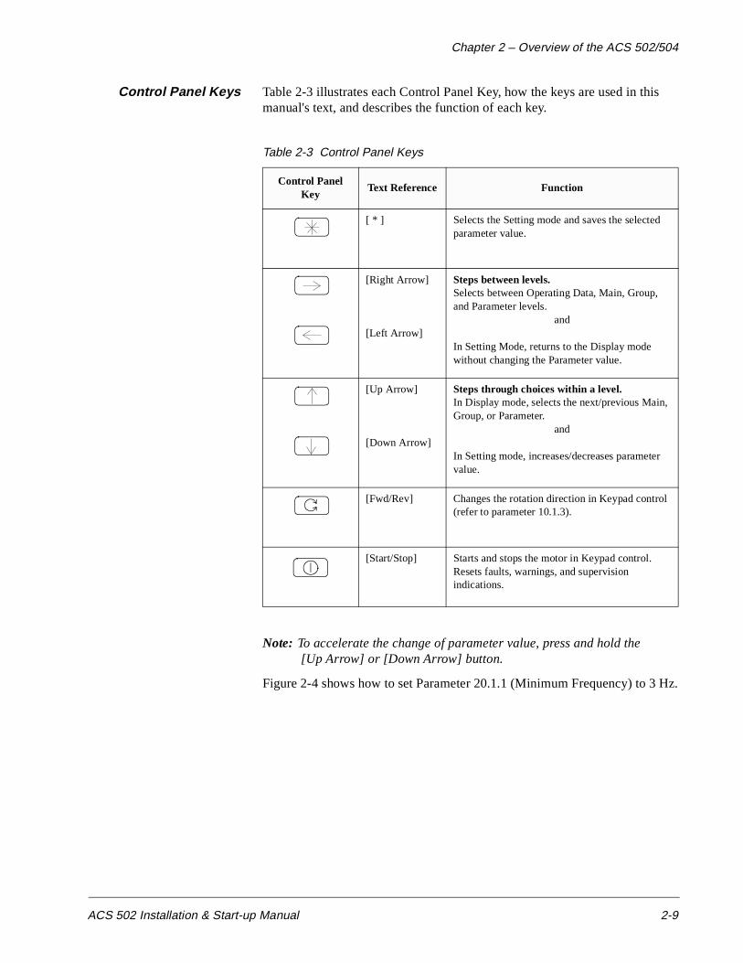
Control Panel Keys Table 2-3 illustrates each Control Panel Key, how the keys are used in this manual's text, and describes the function of each key.
Table 2-3 Control Panel Keys
Note: To accelerate the change of parameter value, press and hold the [Up Arrow] or [Down Arrow] button.
Figure 2-4 shows how to set Parameter 20.1.1 (Minimum Frequency) to 3 Hz.
Control Panel Key
Text Reference Function
[ * ] Selects the Setting mode and saves the selected parameter value.
[Right Arrow]
[Left Arrow]
Steps between levels.Selects between Operating Data, Main, Group, and Parameter levels.
and
In Setting Mode, returns to the Display mode without changing the Parameter value.
[Up Arrow]
[Down Arrow]
Steps through choices within a level.In Display mode, selects the next/previous Main, Group, or Parameter.
and
In Setting mode, increases/decreases parameter value.
[Fwd/Rev] Changes the rotation direction in Keypad control (refer to parameter 10.1.3).
[Start/Stop] Starts and stops the motor in Keypad control. Resets faults, warnings, and supervision indications.

Chapter 2 – Overview of the ACS 502/504
2-10 ACS 502 Installation & Start-up Manual
Figure 2-4 Parameter Settings
Indent to Main level.
Select the required Main.
Indent to Group level. Select the required
Indent to Parameter level. Select the requiredParameter by [Up Arrow] and [Down Arrow]key.
Change to Setting mode. Brackets indicate thatthe parameter value now can be changed.
Set the parameter value. If you want to cancel thechange and return to Display mode, press [RightArrow] or [Left Arrow], otherwise
Save the selected value to parameter memory.Brackets disappear indicating that the parametervalue is stored in memory.
Return to Operating Data parameter 1 (OutputFrequency).
Group by [Up Arrow] and [Down Arrow] keys.

Chapter 2 – Overview of the ACS 502/504
ACS 502 Installation & Start-up Manual 2-11
Adjusting DisplayContrast
The contrast of the LCD can be adjusted for optimal viewing. This can be done when the display is in the Main or Group level.
To adjust contrast, press and hold [ * ] and then press [Up Arrow] or [Down Arrow].
You may need to adjust the display contrast if the ACS 502 has been installed in a location with high ambient temperatures. The factory default setting is optimum for an ambient temperature between 59°F and 86°F (15°C and 30°C).
Application Macros Overview
Application macros are complete sets of default parameter settings for some typical applications. This allows all of the parameters to be set with the touch of a button.
When you select an Application macro, the parameters listed in the ACS 500 Adjustable Frequency AC Drives 2 to 350 HP Programming Manual Including Application Macros are set to a value suitable for a particular application. The parameters which are not included in the Application macro retain the factory settings. If you must adjust the parameter values, refer to the instructions in the ACS 500 Adjustable Frequency AC Drives 2 to 350 HP Programming Manual Including Application Macros.
Hardware Description The ACS 504 chassis units consist of a Control Unit and an Inverter Module. These communicate via a multi-conductor cable.
The ACS 502 series drives consist of an ACS 504 chassis unit mounted in an enclosure.
Inverter Module Figure 2-5 shows the components of the ACS 504. Table 2-4 gives the description of the components.

Chapter 2 – Overview of the ACS 502/504
2-12 ACS 502 Installation & Start-up Manual
Figure 2-5 ACS 504 Components
AAAAAAAAAAAAAAAAAAAAAAAAAAAAAAAAAAAAAAAAAAAAAAA
AAAAAAAAAAAAAAAAAAAAAAAAAAAAAAAAAAAAAAAAAAAA
AAAAAAAAAAAAAAAAAAAAAAAAAAAAAAAAAAAAAAAAAAAAAAAAAAAAAAAAAAAAAAAAAAAAAAAAAAAAAAAAAAAAAAAAAAAAAAAAAAAAAAAAAAAAAAAAAAAAAAAAAAAAAAAAAAAAAAA
AAAAAAAAAAAAAAAAAAAAAAAAAAAAAAAAAAAAAAAAAAAAAAAAAAAAAAAAAAAAAAAA
AAAAAAAAAAAAAAAAAAAAAAAAAAAAAAAAAAAAAAAAAAAAAAAAAAAAAAAAAAAAAAAAAAAAAAAAAAAAAAAAAA
AAAAAAAAAAAAAAAAAAAAAAAAAAAAAAAAAAAAAAAAAAAAAAAAAAAAAAAAAAAAAAAAAAAAAAAAAAAAAAAAAAAAAAAAAAAAAAAAAAAAAAAA
AAAAAAAAAAAAAAAAAAAAAAAAAAAAAAAAAAAAAAAAAAAAAAAAAAAAAAAAAAAAAAAAAAAAAAAAAAAAAAAAAAAAAAAAAAAAAAAAAAAAAAAAAAAAA
AAAAAAAAAAAAAAAAAAAAAAAAAAAAAAAAAAAAAAAAAAAAAAAAAAAAAAAAAAAAAAAAAAAAAAAAAAAAAAAAA
AAAAAAAA
AAAAAAAA
AAAAAAAA
AAAAAAAA
AAAAAAAA
AAAAAAAA
AAAAAAAA
AAAAAAAA
AAAAAAAA
AAAAAAAA
AAAAAAAA
AAAAAAAA
AAAAAAAA
AAAAAAAA
AAAAAAAA
AAAAAAAA
AAAAAAAA
AAAAAAAA
AAAAAAAA
AAAAAAAA
AAAAAAAA
AAAAAAAA
AAAAAAAA
AAAAAAAA
AAAAAAAA
AAAAAAAA
AAAAAAAAAA
AAAAAAAAAAAAAAAAAAAAAAAAAAAAAAAAAAAAAAAAAAAAAAAAAAAAAAAAAAAAAAAAAAAAAAAAAAAAAAAAAAAAAAAAAAAAAAAAAAAAAAAAAAAAAAAAAAAAAAAAAAAAAAAAAAAAAAAAAAAAAAAAAAAAAAAAAAAAAA
X305 X304 X307 X318
X303
X306
X309
X301 X302
X801
X802
X803
X806
X809X805
U1,V1,W1L1, L2, L3
R14
V14
V11,V12,V13
L11
R11
V1,V2,V3V4,V5,V6
U21,U22
3
6 (3)
A8
SNAT 7902 INP
A3
SNAT 7261 INTA7SNAT xyz5 SCLxyz=kVA rating
C14C15C16
S1
X808
X807
Y61(Y62)
T61
II
IU2,IV2
tR718
(30)
PE
U2 T1V2 T2W2 T3
3
UDC+
BR
UDC-
M X310...X315
A4A5X50 X51
X53
X54
X55
X56
SNAT 7780 CNT
X404
X401 X402
X406X407
40 20
10
& KEYPAD
X57
A10
A11
A9
SNAT 780 BRC
V8
X905
X905
(MOTOR TERMINALS)
(BRAKE TERMINALS)
(LINE TERMINALS)
(CONTROL TERMINALS)
CONTROL INTERFACE
DISPLAY
MOTOR CONTROL
MAIN CIRCUITINTERFACE
MATCHING
INVERTERRECTIFIER
INPUT PROTECTION
INVERTER MODULE
CHOPPERCONTROL
OPTIONAL BRAKECHOPPER
(U1)
2
2
CONTROL UNIT
(OPTIONAL)
(OPTIONAL)
acsblkus.drw
X60
SNAT 7670 EFS
X403 X1003 X1003
Chapter 2 – Overview of the ACS 502/504
ACS 502 Installation & Start-up Manual 2-13
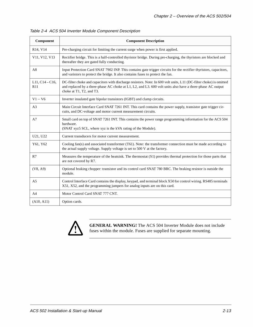
Table 2-4 ACS 504 Inverter Module Component Description
GENERAL WARNING! The ACS 504 Inverter Module does not include fuses within the module. Fuses are supplied for separate mounting.
Component Component Description
R14, V14 Pre-charging circuit for limiting the current surge when power is first applied.
V11, V12, V13 Rectifier bridge. This is a half-controlled thyristor bridge. During pre-charging, the thyristors are blocked and thereafter they are gated fully conducting.
A8 Input Protection Card SNAT 7902 INP. This contains gate trigger circuits for the rectifier thyristors, capacitors, and varistors to protect the bridge. It also contains fuses to protect the fan.
L11, C14 – C16, R11
DC-filter choke and capacitors with discharge resistors. Note: In 600 volt units, L11 (DC-filter choke) is omitted and replaced by a three-phase AC choke at L1, L2, and L3. 600 volt units also have a three-phase AC output choke at T1, T2, and T3.
V1 – V6 Inverter insulated gate bipolar transistors (IGBT) and clamp circuits.
A3 Main Circuit Interface Card SNAT 7261 INT. This card contains the power supply, transistor gate trigger cir-cuits, and DC-voltage and motor current measurement circuits.
A7 Small card on top of SNAT 7261 INT. This contains the power range programming information for the ACS 504 hardware.(SNAT xyz5 SCL, where xyz is the kVA rating of the Module).
U21, U22 Current transducers for motor current measurement.
Y61, Y62 Cooling fan(s) and associated transformer (T61). Note: the transformer connection must be made according to the actual supply voltage. Supply voltage is set to 500 V at the factory.
R7 Measures the temperature of the heatsink. The thermostat (S1) provides thermal protection for those parts that are not covered by R7.
(V8, A9) Optional braking chopper: transistor and its control card SNAT 780 BRC. The braking resistor is outside the module.
A5 Control Interface Card contains the display, keypad, and terminal block X50 for control wiring. RS485 terminals X51, X52, and the programming jumpers for analog inputs are on this card.
A4 Motor Control Card SNAT 777 CNT.
(A10, A11) Option cards.

Chapter 2 – Overview of the ACS 502/504
2-14 ACS 502 Installation & Start-up Manual
WARNING! Parts within the Inverter Module are at main circuit potential. The printed circuit boards within the Control Unit are grounded. The signal isolation takes place in the Inverter Module.
Featuresand Functions
The ACS 502 is an enclosed, floor-standing adjustable frequency AC drive. Depending on the options chosen, the ACS 502 provides motor overload protection, disconnect switch or circuit breaker, bypass, analog meters, indicator lights, and external control connections.
Figure 2-6 shows the door of the ACS 502 and indicates all possible options. Your drive may not look exactly like the illustration.
Figure 2-6 ACS 502 Front Door
VM AM1 AM2 SPM
W Y
POTSS1
OPL
SS2
BPL FPL
RESET
R
ABB Drives
Disconnecthandle
VoltmeterExt. FaultPilot Light
BypassPilot Light
NormalPilot Light
BypassSwitch
HOASwitch
MOLReset
SpeedPot
AmmetersSpeedMeter
Keypad/DigitalDisplay
Chapter 2 – Overview of the ACS 502/504
ACS 502 Installation & Start-up Manual 2-15
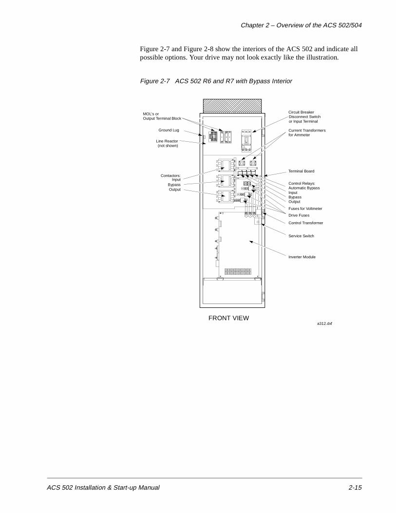
Figure 2-7 and Figure 2-8 show the interiors of the ACS 502 and indicate all possible options. Your drive may not look exactly like the illustration.
Figure 2-7 ACS 502 R6 and R7 with Bypass Interior
F U 5 FU 6
O F F
O N
Ground Lug
Circuit BreakerDisconnect Switchor Input Terminal
Fuses for Voltmeter
MOL's orOutput Terminal Block
Current Transformersfor Ammeter
Control Transformer
Control Relays:Automatic BypassInputBypassOutput
Drive Fuses
Inverter Module
Service Switch
Contactors:
OutputBypass
Input
a312.dxfFRONT VIEW
Terminal Board
Line Reactor(not shown)

Chapter 2 – Overview of the ACS 502/504
2-16 ACS 502 Installation & Start-up Manual
Figure 2-8 ACS 502 R8 with Bypass and R9 Interior
Ground Lug
Output Terminal Block
Current Transformers& Tower Brackets
MOL
Wireduct
Control Relays: OutputBypass
InputAutomatic Bypass
Contactors: OutputBypass
Input
Busbar Jumper
Circuit BreakerDisconnect Switch
or Input Terminal
Terminal Board
Fuses for Voltmeter
Control Transformer
Current Transformersfor Ammeter
Drive Fuses
InverterModule
ServiceSwitch
a302.dxfLine Reactor(not shown)

Chapter 2 – Overview of the ACS 502/504
ACS 502 Installation & Start-up Manual 2-17
Custom Options Custom options for the ACS 502 fall into five main categories:
• Control Options
• Disconnect Options
• Bypass Options
• Thermal Overload Relays
• Meters
Control Options The Control Options are Hand/Off/Auto and Hand/Off/Auto with Speed Potentiometer. Both options include 115 VAC control power and control power transformer. The 115 VAC control can be ordered without Hand/Off/Auto or Speed Potentiometer.
When no control option is ordered, the top half of the terminal board is not used. This board (illustrated in Chapter 3 – ACS 502 Installation Instructions in this manual) is the location of Terminal Block TB1, to which all connections are made. Terminal Board connections are described in this manual. 115 VAC Control is required with all Bypass options.
Hand/Off/Auto Hand/Off/Auto is a door mounted switch, wired at the factory. This switch allows you to select one of three modes. In the Hand mode, the Drive Enable signal enables the drive and the ACS 502 Keypad (Operating Data Parameter 14) controls the speed. In the Off mode, the drive is disabled even if you use an external speed reference or if you attempt to start the drive via the keypad. In the Auto mode, a remote contact closure starts the drive, provided you have connected a remote contact. A remote signal (voltage or current) controls speed. The remote signal controlling speed can also be pneumatic, but requires an option board. The 115 VAC control transformer provides control voltage.
Hand/Off/Auto withSpeed Potentiometer
Hand/Off/Auto with Speed Potentiometer is the same as Hand/Off/Auto with the addition of a manual speed potentiometer mounted on the drive enclosure. In the Hand mode, the speed potentiometer controls the speed.
Input Options The Disconnect Options are the Door Interlocked Disconnect Switch and the Door Interlocked Circuit Breaker.
Door InterlockedDisconnect Switch
The Door Interlocked Disconnect Switch is a non-fused disconnect switch. Fuses are provided as standard, mounted separately.
Door Interlocked CircuitBreaker
The Door Interlocked Circuit Breaker is a thermal magnetic, molded case circuit breaker.
Both options are a thru-the-door interlock design and can be padlocked in the OFF position.
Input Line Reactor 3% or 5% input line reactors to reduce the harmonics to the power line.
Chapter 2 – Overview of the ACS 502/504
2-18 ACS 502 Installation & Start-up Manual
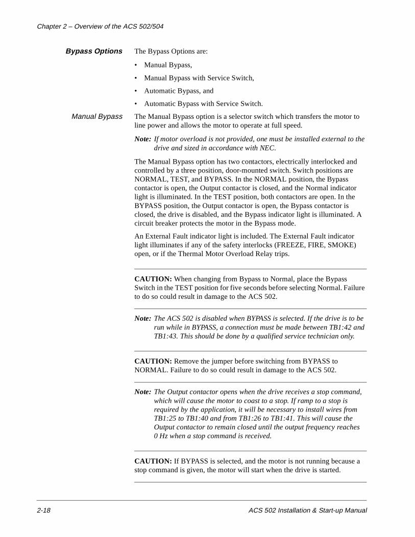
Bypass Options The Bypass Options are:
• Manual Bypass,
• Manual Bypass with Service Switch,
• Automatic Bypass, and
• Automatic Bypass with Service Switch.
Manual Bypass The Manual Bypass option is a selector switch which transfers the motor to line power and allows the motor to operate at full speed.
Note: If motor overload is not provided, one must be installed external to the drive and sized in accordance with NEC.
The Manual Bypass option has two contactors, electrically interlocked and controlled by a three position, door-mounted switch. Switch positions are NORMAL, TEST, and BYPASS. In the NORMAL position, the Bypass contactor is open, the Output contactor is closed, and the Normal indicator light is illuminated. In the TEST position, both contactors are open. In the BYPASS position, the Output contactor is open, the Bypass contactor is closed, the drive is disabled, and the Bypass indicator light is illuminated. A circuit breaker protects the motor in the Bypass mode.
An External Fault indicator light is included. The External Fault indicator light illuminates if any of the safety interlocks (FREEZE, FIRE, SMOKE) open, or if the Thermal Motor Overload Relay trips.
CAUTION: When changing from Bypass to Normal, place the Bypass Switch in the TEST position for five seconds before selecting Normal. Failure to do so could result in damage to the ACS 502.
Note: The ACS 502 is disabled when BYPASS is selected. If the drive is to be run while in BYPASS, a connection must be made between TB1:42 and TB1:43. This should be done by a qualified service technician only.
CAUTION: Remove the jumper before switching from BYPASS to NORMAL. Failure to do so could result in damage to the ACS 502.
Note: The Output contactor opens when the drive receives a stop command, which will cause the motor to coast to a stop. If ramp to a stop is required by the application, it will be necessary to install wires from TB1:25 to TB1:40 and from TB1:26 to TB1:41. This will cause the Output contactor to remain closed until the output frequency reaches 0 Hz when a stop command is received.
CAUTION: If BYPASS is selected, and the motor is not running because a stop command is given, the motor will start when the drive is started.
Chapter 2 – Overview of the ACS 502/504
ACS 502 Installation & Start-up Manual 2-19
Manual Bypass withService Switch
The Manual Bypass with Service Switch option is the same as the Manual Bypass option with the addition of another switch, and a third (input) contactor on the line power side of the drive. The additional switch allows you to apply power to, or remove power from the drive for servicing while the motor continues to operate on line power. In the BYPASS position, the Drive Input contactor opens and removes power from the drive. The Drive Input contactor is also controlled by the three position Service Switch, with the positions labeled NORMAL, OFF, and TEST. This switch is mounted inside the enclosure. In the NORMAL position, the Bypass switch controls the Drive Input contactor. In the TEST position, the Drive Input contactor is closed. In the OFF position, the Drive Input contactor is open.
Note: The Drive Input contactor opens when BYPASS is selected, removing power from the drive. The service switch will energize the input contactor in the TEST position to allow the drive to be powered while in BYPASS for servicing.
Note: The ACS 502 is disabled when BYPASS is selected. If the drive is to be run while in BYPASS, a connection must be made between TB1:42 and TB1:43. This should be done by a qualified service technician only.
CAUTION: Return the service switch to Normal and remove the jumper from TB1:42 to TB1:43 before switching from BYPASS to NORMAL. Failure to do so could result in damage to the ACS 502.
Note: The Output contactor opens when the drive receives a stop command, which will cause the motor to coast to a stop. If ramp to a stop is required by the application, it will be necessary to install wires from TB1:25 to TB1:40 and from TB1:26 to TB1:41. This will cause the Output contactor to remain closed until the output frequency reaches 0 Hz when a stop command is received.
CAUTION: If BYPASS is selected, and the motor is not running because a stop command is given, the motor will start when the drive is started.
Chapter 2 – Overview of the ACS 502/504
2-20 ACS 502 Installation & Start-up Manual
Automatic Bypass An Automatic Bypass may be added to the Manual Bypass or Manual Bypass with Service Switch. The Automatic Bypass automatically transfers the motor to line power when the drive shuts down on a protective trip. If Automatic Restart is enabled on the drive, the drive will attempt to automatically restart before the motor transfers to line power. Bypass transfer occurs when the drive is in a fault condition and will not reset. When an automatic transfer occurs, the Bypass indicator light illuminates.
Thermal MotorOverload Relays
The Thermal Motor Overload Relay Options are relays rated 30, 60, 100, or 180 amps in-line with the output power, and 26 amp relay with 500:5 current transformers for ratings from 180 to 500 amps. These options are standard, manually resettable, bimetallic motor overload relays with a Class 20 trip curve. The relays provide thermal motor protection when operating a motor from the drive. If a Bypass Option is included, the relays also provide thermal motor protection across the line power. If the overload trips, power is removed from the motor whether in Normal or Bypass mode. When the drive has the Bypass option, an external fault indicator is included. This indicator will illuminate if the overload relay trips. The overload relay is reset by a pushbutton on the enclosure door.
Thermal Motor Overload Relays have heater elements to determine the trip level of the overload relay. The heater element type is stamped on the element. If the overload is not sized properly for the motor, purchase new heaters of the correct size. See the following tables for heater sizes. Table 2-6 shows heater sizes for the 30, 60, 100, and 180 amp Furnas relays. Table 2-7 is for ratings over 180 amps, which are Square D devices. Your ACS 502 may have either one or two overload relays, depending upon how many motors the drive controls.
Chapter 2 – Overview of the ACS 502/504
ACS 502 Installation & Start-up Manual 2-21
Table 2-5 Heater Sizes for Furnas Relays
Furnas Heater Code
Amps 30 60 100 180
E3E4E5E6E7
.30 – .32
.33 – .35
.36 – .38
.39 – .41
.42 – .44
E8E9E11E12E13
.45 – .49
.50 – .54
.55 – .58
.59 – .63
.64 – .67
E14E16E17E18E19
.68 – .73
.74 – .81
.82 – .87
.88 – .94.95 – 1.00
E23E24E26E27E28
1.10 – 1.101.11 – 1.261.27 – 1.401.41 – 1.581.59 – 1.74
E29E31E32E33E34
1.75 – 1.851.86 – 1.992.00 – 2.112.12 – 2.312.32 – 2.59
E36E37E38E39E41
2.60 – 2.752.76 – 2.952.96 – 3.213.22 – 3.483.49 – 3.89
E42E44E46E47E48
3.90 – 4.354.36 – 4.734.74 – 5.215.22 – 5.745.75 – 6.05
E49E50E51E52E53
6.06 – 6.466.47 – 6.956.96 – 8.098.10 – 9.299.30 – 10.4
E54E55E56E57E60
10.5 – 10.911.0 – 12.012.1 – 14.514.6 – 16.8
Chapter 2 – Overview of the ACS 502/504
2-22 ACS 502 Installation & Start-up Manual
E61E62E65E66E67
16.9 – 18.418.5 – 20.921.0 – 22.522.6 – 24.324.4 – 27.2
16.9 – 18.418.5 – 20.921.0 – 22.522.6 – 24.724.8 – 27.2 27.1 – 30.0
E69E70E71E72E73
27.3 – 29.229.3 – 30.0
27.3 – 29.229.3 – 32.032.1 – 34.9
35.0 – 37.8
30.1 – 33.233.3 – 35.735.8 – 39.439.5 – 43.443.5 – 46.9
E73AE74E76E77E78
37.9 – 41.741.8 – 45.946.0 – 49.049.1 – 54.254.3 – 60.0
47.0 – 51.551.6 – 57.057.1 – 62.862.9 – 69.1
E79E80E88E89E91
69.2 – 75.075.1 – 83.3
50.0 – 55.956.0 – 60.961.0 – 65.9
E92E93E94E96E97
83.4 – 86.987.0 – 92.9
66.0 – 69.970.0 – 75.976.0 – 81.982.0 – 86.987.0 – 92.9
E98E99E101E102E103
93.0 – 100.0 93.0 – 97.998.0 – 107.9108.0 – 113.9114.0 – 125.9126.0 – 138.9
E104E106E107
139.0 – 153.0154.0 – 163.0164.0 – 180.0
Furnas Heater Code
Amps 30 60 100 180
Chapter 2 – Overview of the ACS 502/504
ACS 502 Installation & Start-up Manual 2-23
Table 2-6 Heater Sizes for Square D Relays
Heater Code Amps
AR .45 28.0 – 30.0
AR .49 31.0 – 33.0
AR .54 34.0 – 36.0
AR .59 37.0 – 39.0
AR .65 40.0 – 42.0
AR .71 43.0 – 46.0
AR .78 47.0 – 50.0
AR .86 51.0 – 52.0
AR .95 53.0 – 56.0
AR 1.05 57.0 – 60.0
AR 1.15 61.0 – 66.0
AR 1.26 67.0 – 73.0
AR 1.39 74.0 – 81.0
AR 1.53 82.0 – 90.0
AR 1.68 91.0 – 105.0
AR 1.85 106.0 – 115.0
AR 2.04 116.0 – 125.0
AR 2.24 126.0 – 135.0
AR 2.46 136.0 – 147.0
AR 2.71 148.0 – 158.0
AR 2.98 159.0 – 174.0
AR 3.28 175.0 – 194.0
AR 3.62 195.0 – 220.0
AR 3.98 221.0 – 247.0
AR 4.37 248.0 – 276.0
AR 4.80 277.0 – 307.0
AR 5.3 308.0 – 345.0
AR 5.8 346.0 – 381.0
AR 6.4 382.0 – 420.0
AR 7.0 421.0 – 465.0
Chapter 2 – Overview of the ACS 502/504
2-24 ACS 502 Installation & Start-up Manual
Meters The Meter Options are Output Voltmeter, Output Speed Meter, and Output Ammeter. A total of four analog meters can be installed in the ACS 502.
Output Voltmeter The Output Voltmeter indicates motor voltage on a 0 – 500 VAC scale connected directly to the drive output.
Output Speed Meter The Output Speed Meter is calibrated in percent of maximum speed with a 0 – 100 percent scale connected to one of the analog outputs.
Note: This option uses one of the analog outputs on the ACS 502.
Output Ammeters The Ammeters have six calibration sizes ranging from 100 to 500 amps. Depending on the number of motors driven, one or two Output Ammeters can be installed in the ACS 502. If two ammeters are ordered, two Thermal Motor Overload Relays must be ordered; the ammeters are sized to the Thermal Motor Overload Relays. If two Thermal Motor Overload Relays are ordered and only one ammeter is ordered, the ammeter will indicate the sum of the current at the two relays.

ACS 502 Installation & Start-up Manual 3-1
Chapter 3 – ACS 502 Installation Instructions
This chapter explains how to install the ACS 502 and connect all power, motor, and control wiring. It also describes the initial inspection procedures.
Grounding and Ground Faults
The ACS 502 must always be grounded through a ground conductor connected to the ground terminal.
If the ACS 502 is connected to a system without system ground, the ground fault protection must be capable of starting at ground fault currents containing high frequency and DC components. The ACS 502 ground fault protection guards the variable frequency drive against ground faults occurring in the motor or the motor wiring.Fault current protective switches do not necessarily operate properly with variable frequency drives. When using such switches their function should be checked at possible ground fault currents arising in a fault situation.
Pre-Installation Planning
This drive has been tested in accordance with UL508. 480 VAC units: The drives are suitable for use on a circuit capable of delivering not more than 42,000 rms Amperes, 500 Volts maximum.
When circuit breakers are supplied, the drive package is limited to the rating of the circuit breaker, which is 18,000 rms Amperes for the 50 & 60 HP units; 25,000 for the 75 - 125 HP units; and 30,000 for the 150 - 400 HP units.600 VAC units: are suitable for use on a circuit capable of delivering not more than 42,000 rms Amperes, 600 Volts. When circuit breakers are supplied, the drive package is limited to the rating of the circuit breaker, which is 14,000 rms Amperes.
When output chokes are supplied, 480 and 600 VAC units are suitable for use on a circuit capable of delivering not more than 65,000 rms Amperes, 500 Volts or 600 Volts.
Environment These drives are to be used in a heated, indoor controlled environment that is relatively free of moisture and conductive contaminates such as condensation, carbon dust, and the like.
The maximum ambient temperature allowed is 113°F (45°C) for an ACS 502 in a NEMA 1 enclosure for constant torque loads, when the load current is lower than or equal to the continuous rated constant torque current (IR). The maximum ambient temperature allowed is 104°F (40°C) for an ACS 502 in a NEMA 12 enclosure for constant torque loads; and an ACS 502 in a NEMA 1 enclosure for variable torque loads, when the load current is lower than or equal to the continuous maximum load current (IRSQ).
The cooling air must be clean and free from corrosive materials. When necessary the required cooling should be provided by using clean, dry air. If the cooling air contains dust, clean the cooling surfaces of the unit regularly using compressed air and a brush.
Chapter 3 – ACS 502 Installation Instructions
3-2 ACS 502 Installation & Start-up Manual
If the heatsink is not cleaned and it is not able to dissipate the expended heat, the ACS 502’s thermal protection will operate, causing a fault indication which stops the drive. The ACS 502 can be started again when the temperature of the heatsink has fallen below 167°F (75°C).
The temperature of the heatsink can be read from the Control Panel Display Operating Data, Parameter 8 (Drive Temperature).
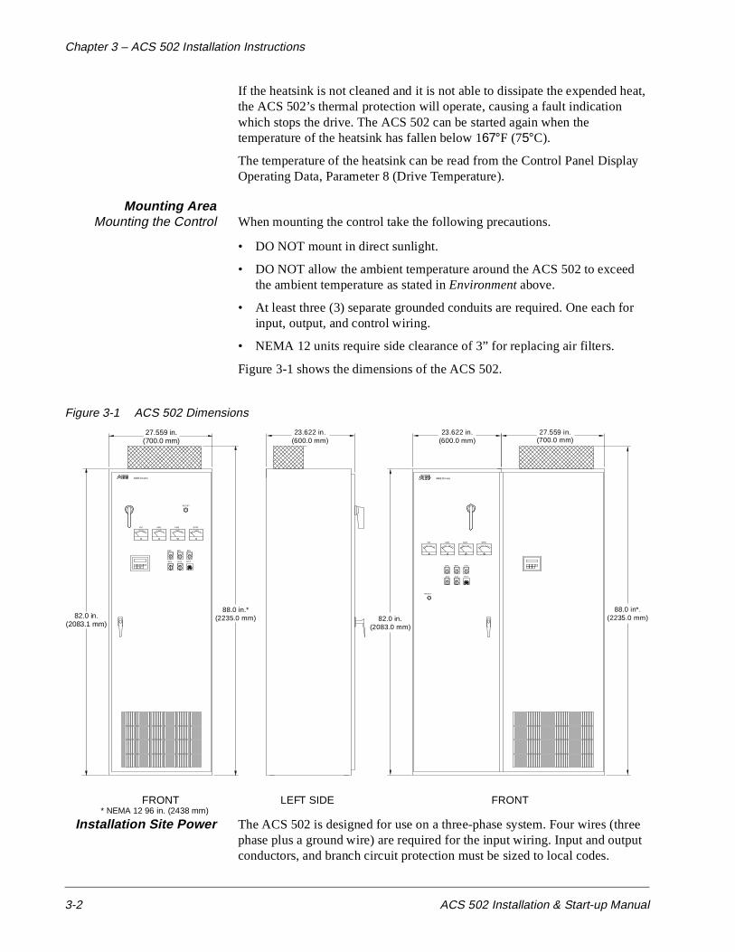
Mounting AreaMounting the Control When mounting the control take the following precautions.
• DO NOT mount in direct sunlight.
• DO NOT allow the ambient temperature around the ACS 502 to exceed the ambient temperature as stated in Environment above.
• At least three (3) separate grounded conduits are required. One each for input, output, and control wiring.
• NEMA 12 units require side clearance of 3” for replacing air filters.
Figure 3-1 shows the dimensions of the ACS 502.
Figure 3-1 ACS 502 Dimensions
Installation Site Power The ACS 502 is designed for use on a three-phase system. Four wires (three phase plus a ground wire) are required for the input wiring. Input and output conductors, and branch circuit protection must be sized to local codes.
88.0 in*.(2235.0 mm)
FRONTLEFT SIDE
VM AM1 AM2 SPM
PO TS S1
OPL BP L FPL
RES ET
ABB Drives
23.622 in.(600.0 mm)
23.622 in.(600.0 mm)
27.559 in.(700.0 mm)
82.0 in.(2083.0 mm)
SS2
FRONT
VM AM 1 A M2 S PM
PO TS S1
OPL
SS2
BPL FPL
RE SET
ABB Drives
27.559 in.(700.0 mm)
82.0 in.(2083.1 mm)
88.0 in.*(2235.0 mm)
* NEMA 12 96 in. (2438 mm)

Chapter 3 – ACS 502 Installation Instructions
ACS 502 Installation & Start-up Manual 3-3
Conduit Size Figure 3-2 and Figure 3-3 show top views of the ACS 502 and conduit entry area. The panels must be removed from the drive before being drilled and punched to prevent metal particles from falling into the drive.
Figure 3-2 ACS 502 Conduit Entry Area for One Door Enclosure
Figure 3-3 ACS 502 Conduit Entry Area for Two Door Enclosure
Figure 3-3 shows the left bay at the enclosure only.
TOP VIEW
5.906 in.(150.0 mm)
27.559 in.(700.0 mm)
23.622 in.(600.0 mm)
24.516 in.(622.7 mm)
12.113 in.(307.7 mm)
Recommended areafor entry/exit
150.00 mm[5.906"]
600.00 mm[23.622"]
480.04 mm [18.899"]
491.55 mm[19.352"]
553.25 mm [21.781"]
a300.dxf
Chapter 3 – ACS 502 Installation Instructions
3-4 ACS 502 Installation & Start-up Manual
Power Wiring All field wiring shall be rated for 167°F (75°C).
Install the motor wiring away from other wire routes. Avoid long parallel runs with other wires.
The tightening torque for the input power connections to the circuit breaker should be 275 in.-lbs. Tightening torques to other termination points should be as labeled on the device.
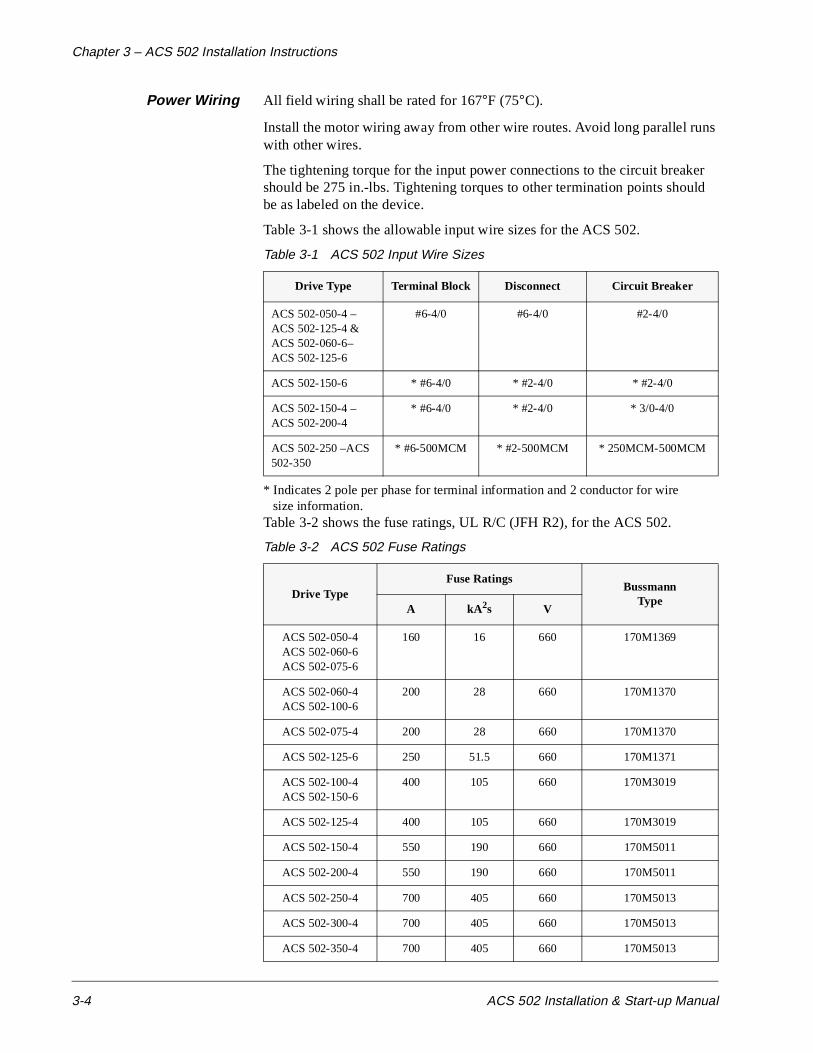
Table 3-1 shows the allowable input wire sizes for the ACS 502.
Table 3-1 ACS 502 Input Wire Sizes
* Indicates 2 pole per phase for terminal information and 2 conductor for wire size information.
Table 3-2 shows the fuse ratings, UL R/C (JFH R2), for the ACS 502.
Table 3-2 ACS 502 Fuse Ratings
Drive Type Terminal Block Disconnect Circuit Breaker
ACS 502-050-4 –ACS 502-125-4 & ACS 502-060-6–ACS 502-125-6
#6-4/0 #6-4/0 #2-4/0
ACS 502-150-6 * #6-4/0 * #2-4/0 * #2-4/0
ACS 502-150-4 –ACS 502-200-4
* #6-4/0 * #2-4/0 * 3/0-4/0
ACS 502-250 –ACS 502-350
* #6-500MCM * #2-500MCM * 250MCM-500MCM
Drive Type Fuse Ratings
BussmannType
A kA2s V
ACS 502-050-4ACS 502-060-6ACS 502-075-6
160 16 660 170M1369
ACS 502-060-4ACS 502-100-6
200 28 660 170M1370
ACS 502-075-4 200 28 660 170M1370
ACS 502-125-6 250 51.5 660 170M1371
ACS 502-100-4ACS 502-150-6
400 105 660 170M3019
ACS 502-125-4 400 105 660 170M3019
ACS 502-150-4 550 190 660 170M5011
ACS 502-200-4 550 190 660 170M5011
ACS 502-250-4 700 405 660 170M5013
ACS 502-300-4 700 405 660 170M5013
ACS 502-350-4 700 405 660 170M5013
Chapter 3 – ACS 502 Installation Instructions
ACS 502 Installation & Start-up Manual 3-5
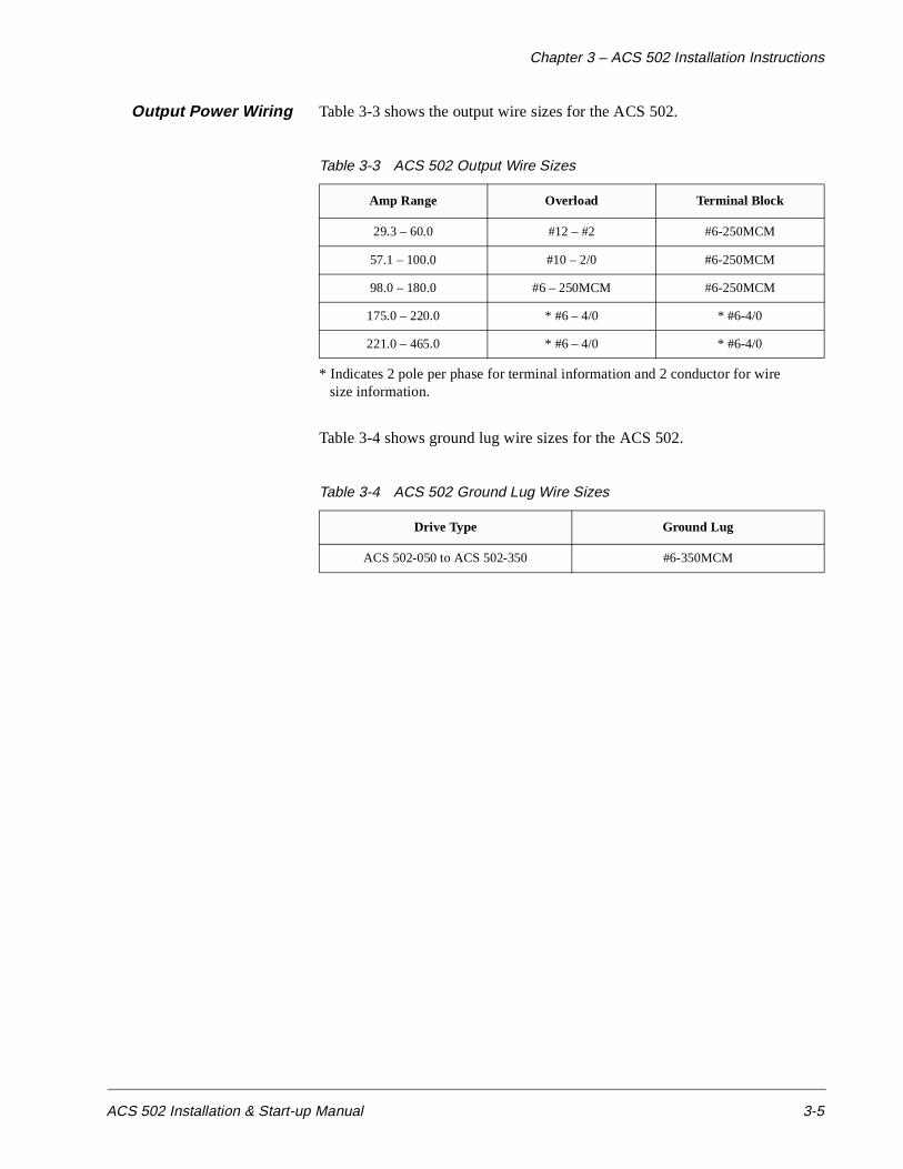
Output Power Wiring Table 3-3 shows the output wire sizes for the ACS 502.
Table 3-3 ACS 502 Output Wire Sizes
* Indicates 2 pole per phase for terminal information and 2 conductor for wire size information.
Table 3-4 shows ground lug wire sizes for the ACS 502.
Table 3-4 ACS 502 Ground Lug Wire Sizes
Amp Range Overload Terminal Block
29.3 – 60.0 #12 – #2 #6-250MCM
57.1 – 100.0 #10 – 2/0 #6-250MCM
98.0 – 180.0 #6 – 250MCM #6-250MCM
175.0 – 220.0 * #6 – 4/0 * #6-4/0
221.0 – 465.0 * #6 – 4/0 * #6-4/0
Drive Type Ground Lug
ACS 502-050 to ACS 502-350 #6-350MCM
Chapter 3 – ACS 502 Installation Instructions
3-6 ACS 502 Installation & Start-up Manual
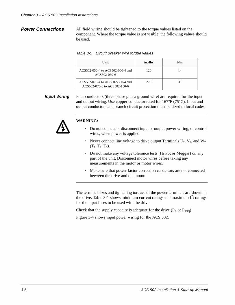
Power Connections All field wiring should be tightened to the torque values listed on the component. Where the torque value is not visible, the following values should be used.
Table 3-5 Circuit Breaker wire torque values
Input Wiring Four conductors (three phase plus a ground wire) are required for the input and output wiring. Use copper conductor rated for 167°F (75°C). Input and output conductors and branch circuit protection must be sized to local codes.
WARNING:
• Do not connect or disconnect input or output power wiring, or control wires, when power is applied.
• Never connect line voltage to drive output Terminals U2, V2, and W2 (T1, T2, T3).
• Do not make any voltage tolerance tests (Hi Pot or Meggar) on any part of the unit. Disconnect motor wires before taking any measurements in the motor or motor wires.
• Make sure that power factor correction capacitors are not connected between the drive and the motor.
The terminal sizes and tightening torques of the power terminals are shown in the drive. Table 3-1 shows minimum current ratings and maximum I2t ratings for the input fuses to be used with the drive.
Check that the supply capacity is adequate for the drive (PR or PRSQ).
Figure 3-4 shows input power wiring for the ACS 502.
Unit in.-lbs Nm
ACS502-050-4 to ACS502-060-4 and ACS502-060-6
120 14
ACS502-075-4 to ACS502-350-4 and ACS502-075-6 to ACS502-150-6
275 31

Chapter 3 – ACS 502 Installation Instructions
ACS 502 Installation & Start-up Manual 3-7
Figure 3-4 Input Power Wiring
Output Wiring Sizing is the same as for the input wiring.
Figure 3-5 shows output power wiring for the ACS 502.
Figure 3-5 Output Power Wiring
R8 w/bypass and R9 (all)
R6 & R7 (all) and R8 w/o bypass
a317.dxfa318.dxf
R8 w/bypass and R9 (all)
R6 & R7 (all) and R8 w/o bypass
a317.dxfa318.dxf

Chapter 3 – ACS 502 Installation Instructions
3-8 ACS 502 Installation & Start-up Manual
Dynamic Braking When Dynamic Braking is required, connection is made to the DC bus terminals. Dynamic Braking can be accomplished in two ways.
1. Internal Dynamic Brake Chopper. If the ACS 502 was provided from the factory with dynamic braking, the control logic and power switch for the dynamic braking are built into the drive. The DC bus voltage is present at the DC bus terminals only when the DC bus voltage exceeds the braking threshold due to regeneration.To determine if the internal dynamic braking chopper has been supplied, first check the part number as described in Chapter 2 – Overview of the ACS 502/504. If the internal dynamic braking chopper is supplied, an external resistor load bank is connected to the Brake terminal (BR) and positive DC bus terminal (UDC+).
WARNING! Before connecting a resistor load bank to the DC bus terminals, measure the voltage at the terminals with power applied to the ACS 502. Use a meter rated greater than 1000 VDC. The voltage should be zero volts. If the voltage is 1.35 x VIN, the internal braking chopper is not present, DO NOT CONNECT LOAD BANK RESISTORS.
2. External Dynamic Braking Device. If the internal dynamic brake chopper was not supplied and dynamic braking is required for the application, an external dynamic braking chopper and resistor load bank can be connected to the DC bus terminals.
WARNING! The brake control terminals carry a dangerous DC voltage (1.35 x VIN). No device other than an ABB Drives dynamic braking device may be connected to the positive and negative terminals of Terminal Block X2.
Control Connections
Available ControlLocations
The ACS 502 can be controlled from the Keypad located on the front of the enclosure or with an external control device.
External control devices, for example a PLC or remote operator devices, can be connected to Terminal Block TB1. These control devices can be Analog or Digital. Refer to Terminal Block Connections in this chapter.
When planning control wiring from ACS 502 and external control devices consider the following:
1. All external control wiring to TB1:1 to TB1:20 must be done with shielded cable and must not be run in the same conduit or raceway with any high power wiring. The shield connection must be terminated at the chassis ground lug provided. The other end of the shield should be cut and taped back at the signal source.
Chapter 3 – ACS 502 Installation Instructions
ACS 502 Installation & Start-up Manual 3-9
2. TB1 terminals 2 and 8 are “GND 2” (circuit common). TB1 terminals 4, 6, 18, and 20 are also connected to circuit common.
3. These terminals are optically isolated from power and isolated from chassis ground by a 10 megohm resistor. They are not isolated from one another.
4. Refer to the Terminal Block Connections section in this chapter for an outline of control signal requirements when selecting an Application macro.
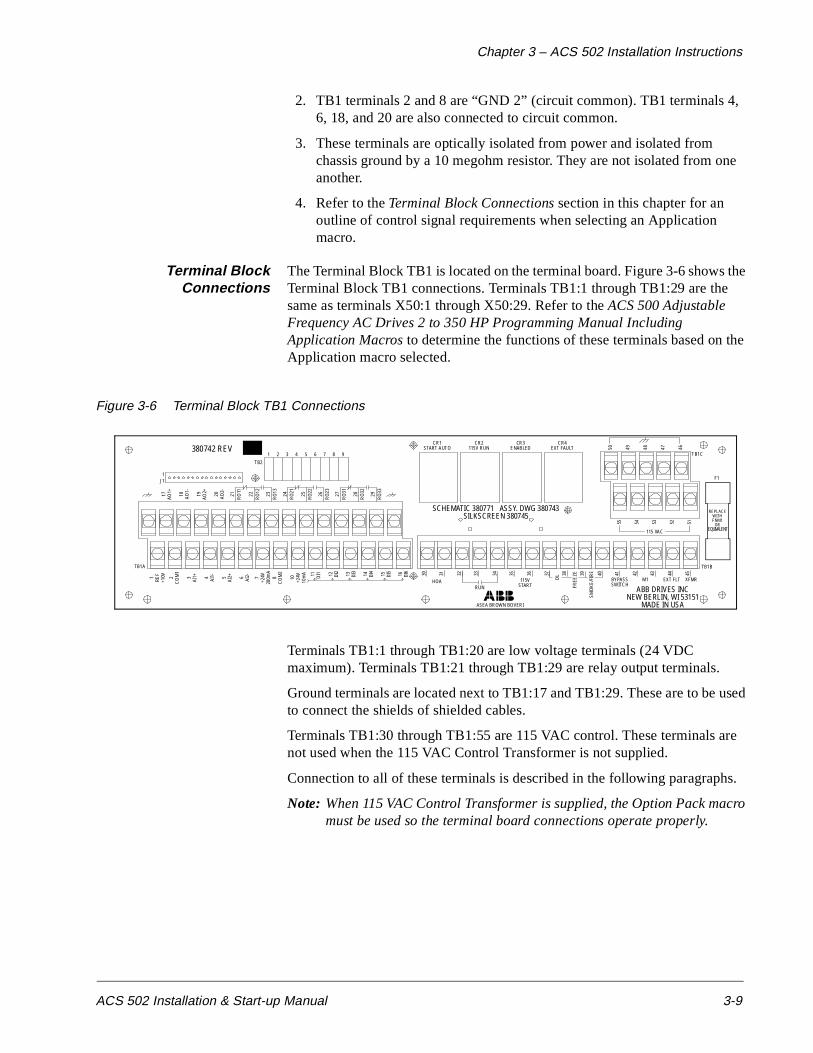
Terminal BlockConnections
The Terminal Block TB1 is located on the terminal board. Figure 3-6 shows the Terminal Block TB1 connections. Terminals TB1:1 through TB1:29 are the same as terminals X50:1 through X50:29. Refer to the ACS 500 Adjustable Frequency AC Drives 2 to 350 HP Programming Manual Including Application Macros to determine the functions of these terminals based on the Application macro selected.
Figure 3-6 Terminal Block TB1 Connections
Terminals TB1:1 through TB1:20 are low voltage terminals (24 VDC maximum). Terminals TB1:21 through TB1:29 are relay output terminals.
Ground terminals are located next to TB1:17 and TB1:29. These are to be used to connect the shields of shielded cables.
Terminals TB1:30 through TB1:55 are 115 VAC control. These terminals are not used when the 115 VAC Control Transformer is not supplied.
Connection to all of these terminals is described in the following paragraphs.
Note: When 115 VAC Control Transformer is supplied, the Option Pack macro must be used so the terminal board connections operate properly.
380742 REV
J11
17AO
1+
18 AO1-
19AO
2+
20 AO2-
21R
O11
22R
O12
23R
O13
24R
O21
25R
O22
26R
O23
27R
O31
28R
O32
29R
O33
TB2
1 2 3 4 5 6 7 8 9
TB1A
1 REF
+10V 2
CO
M1
3AI
1+ 4 AI1- 5
AI2+ 6 AI2- 7
+24V
200m
A8
CO
M2
10 +24V
10m
A 11 DI1 12 DI2
13 DI3
14 DI4
15 DI5
16 DI6 30 31 32 33 34 35 36 37 38 39 40 41 42 43 44 45
HOARUN
115VSTART
OL
FREE
ZE
SMO
KE/
FIR
E
BYPASSSWITCH
M1 EXT FLT XFMR
TB1B
ASEA BROWN BOVERI
ABB DRIVES INCNEW BERLIN, WI 53151
MADE IN USA
115 VAC
55 54 53 52 51
50 49 48 47 46
SCHEMATIC 380771 ASSY. DWG 380743SILKSCREEN 380745
CR1START AUTO
CR2115V RUN
CR3ENABLED
CR4EXT FAULT
TB1C
F1
REPLACEWITHFNM1
OREQUIVALENT
Chapter 3 – ACS 502 Installation Instructions
3-10 ACS 502 Installation & Start-up Manual
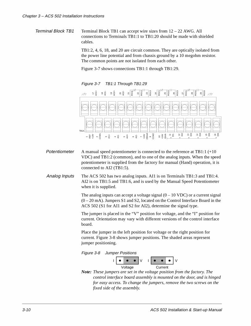
Terminal Block TB1 Terminal Block TB1 can accept wire sizes from 12 – 22 AWG. All connections to Terminals TB1:1 to TB1:20 should be made with shielded cables.
TB1:2, 4, 6, 18, and 20 are circuit common. They are optically isolated from the power line potential and from chassis ground by a 10 megohm resistor. The common points are not isolated from each other.
Figure 3-7 shows connections TB1:1 through TB1:29.
Figure 3-7 TB1:1 Through TB1:29
Potentiometer A manual speed potentiometer is connected to the reference at TB1:1 (+10 VDC) and TB1:2 (common), and to one of the analog inputs. When the speed potentiometer is supplied from the factory for manual (Hand) operation, it is connected to AI2 (TB1:5).
Analog Inputs The ACS 502 has two analog inputs. AI1 is on Terminals TB1:3 and TB1:4. AI2 is on TB1:5 and TB1:6, and is used by the Manual Speed Potentiometer when it is supplied.
The analog inputs can accept a voltage signal (0 – 10 VDC) or a current signal (0 – 20 mA). Jumpers S1 and S2, located on the Control Interface Board in the ACS 502 (S1 for AI1 and S2 for AI2), determine the signal type.
The jumper is placed in the “V” position for voltage, and the “I” position for current. Orientation may vary with different versions of the control interface board.
Place the jumper in the left position for voltage or the right position for current. Figure 3-8 shows jumper positions. The shaded areas represent jumper positioning.
Figure 3-8 Jumper Positions
Note: These jumpers are set in the voltage position from the factory. The control interface board assembly is mounted on the door, and is hinged for easy access. To change the jumpers, remove the two screws on the fixed side of the assembly.
17
AO
1+
18 AO
1-
19
AO
2+
20 AO
2-
21
RO
11
22
RO
12
23
RO
13
24
RO
21
25
RO
22
26
RO
23
27
RO
31
28
RO
32
29
RO
33
TB1A
1
RE
F
+1
0V 2
CO
M1
3
AI1
+
4 AI1
-
5
AI2
+
6 AI2
-
7
+2
4V
200
mA
8
CO
M2
10
+2
4V
10m
A 11 DI1 12 DI2 13 DI3 14 DI4 15 DI5 16 DI6
VI
Voltage
VI
CurrentABB0045A

Chapter 3 – ACS 502 Installation Instructions
ACS 502 Installation & Start-up Manual 3-11
Auxiliary 24 VDC An auxiliary +24 VDC supply is available on Terminals TB1:7 and TB1:8. This supply can drive auxiliary devices whose total current draw is less than 200 mA.
Digital Inputs TB1 has six digital inputs, DI1 through DI6 on Terminals TB1:11 through TB1:16 respectively. The digital inputs use 24 VDC logic from terminal TB1:10 and are active high.
DI1, DI2, DI5, and DI6 are used by the logic on the Terminal Board when the 115 VAC control transformer is supplied. DI3 and DI4 can be used for Preset Speeds or floating point control.
Analog Outputs TB1 has two analog output signals. AO1 is on Terminals TB1:17 and TB1:18. AO2 is on TB1:19 and TB1:20. These signals are 0 – 20 mA (or 4 – 20 mA), and can operate into a maximum 500 ohm load. When the Speed Meter is supplied, it uses AO1.
Digital (Relay) Outputs Three relay outputs are each Form C. Relay RO1 is on Terminals TB1:21, TB1:22, and TB1:23. Relay RO2 is on Terminals TB1:24, TB1:25, and TB1:26. Relay RO3 is on Terminals TB1:27, TB1:28, and TB1:29.
The first terminal for each relay is the normally closed (NC) terminal, the second is the common, and the third is the normally open (NO) terminal.
Maximum Switching Voltage: 300 VDC / 250 VAC.
Maximum Switching Current/Power: 8 A @ 24 VDC, 0.4 A @ 250 VDC, or 2000 VA @ 250 VAC.
Maximum Continuous Current: 2 A rms.
If the relay outputs are used to control inductive loads, such as the coils of relays or contactors, some form of noise supression must be provided at the load. This is to reduce the electrical noise that could interfere with the electronics in the drive, as well as increase the life of the contacts in the relay.
AC coils should be supressed with an MOV (metal oxide varistor) or a Series-Connected RC (resistor capacitor) network, as illustrated below:
MOV should be rated 120 VAC - 240 VAC for 115 VAC circuits, 240 VAC - 320 VAC for 230 VAC circuits, minimum 10 joules. Values for the RC Network vary, as they effect the opening and closing time. Contact the contactor manufacturer for recommended values.
X50MOV
X50
RC network
115 VAC
115 VAC

Chapter 3 – ACS 502 Installation Instructions
3-12 ACS 502 Installation & Start-up Manual
DC coils should be supressed with a diode, although this is not required because of the small amount of noise generated by these type of circuits. If a diode is used, it should have a voltage rating greater than or equal to the supply voltage, and be connected as shown below:
Figure 3-9 shows connections TB1:32 through TB1:40.
Note: The 115 VAC control transformer must be supplied for these terminals to be active.
Figure 3-9 TB1:32 Through TB1:40
Two-Wire Start(Dry Contact)
To start the ACS 502 by dry contact (maintained), connect contact to TB1:32 and TB1:34. This will start the drive in Auto when HOA is supplied, and will start and stop the motor in Bypass when Bypass is supplied.
115 VAC Start To start the ACS 502 by applying 115 VAC, connect the 115 VAC signal to TB1:35 and TB1:36. Operation is the same as Two-Wire Start.
Freeze/Fire/SmokeProtection
Safety interlocks, such as Freeze, Fire, and Smoke protection are normally closed dry contacts connected in series between TB1:38, TB1:39, and TB1:40. Remove the jumper wire before making your connection. When the contact opens, the motor will stop, whether in NORMAL or BYPASS. When the External Fault indicator is provided (supplied with Bypass Option), the indicator will illuminate when any of these contacts open.
115 VAC Auxiliary Power 115 VAC is available for customer use. There is approximately 100 VA available. TB1:46 through TB1:50 are ground, and TB1:51 through TB1:55 are hot.
Figure 3-10 shows connections TB1:46 through TB1:55.
Figure 3-10 TB1:46 Through TB1:55
X50diode (24 VDC in this case)
24 VDC-
+
32 33 34 35 36 37 38 39 40
RUN115V
START
OL
FREE
ZE
SMO
KE/F
IRE
115 VAC
55 54 53 52 51
50 49 48 47 46
ACS 502 Installation & Start-up Manual 4-1
Chapter 4 – ACS 504 Installation Instructions
This chapter explains how to properly install an ACS 504 chassis unit
The ACS 504 chassis includes:
• ACS 504 Inverter Module
• Control Unit including cable (6 feet)
• Control Unit Brackets
• Input Fuses (supplied loose)
• Fuse Holder (supplied loose)
• Control Label (supplied loose)
• Ground fault current transformer
• Input choke (600 volt units only)
Pre-Installation Planning
This drive has been tested in acccordance with UL508. 480 VAC units: The drives are suitable for use on a circuit capable of delivering not more than 42,000 rms Amperes, 500 Volts maximum. 600 VAC units: are suitable for use on a circuit capable of delivering not more than 42,000 rms Amperes, 600 Volts.
When output chokes are supplied, 480 and 600 VAC units are suitable for use on a circuit capable of delivering not more than 65,000 rms Amperes, 500 Volts or 600 Volts.
Careful planning is required to insure proper operation of the ACS 504. The information provided in this chapter includes all dimensions, cooling requirements, and wiring information.
Figure 4-1 shows the dimensional drawings of the ACS 504 Inverter Module and Figure 4-3 shows the dimensional drawings of the ACS 504 Control Unit. Figure 4-2 shows the foot print dimensional drawing of the Inverter Module. Table 4-2 gives the dimensions and approximate weights of the Inverter Module.
Figure 4-1 shows the dimensions of the Inverter Modules. Dimensions marked with letters and numbers are found in Table 4-2. Numbers are in inches (mm).

Chapter 4 – ACS 504 Installation Instructions
4-2 ACS 502 Installation & Start-up Manual
Figure 4-1 Inverter Module Dimensions
Table 4-1 ACS 504 Inverter Module Weights
R6 R7 R8 R9
Weight (lb) 137 196 278 364
Weight (kg) 62 89 126 165
BRUDC+
UDC-
D4
D3
D1D2
V2
W2
U2
PE
1.50(38)
5.51(140)
5.51(140)
COOLING AIRINLET
COOLING AIR OUTLET
NAME PLATEBRAKING CHOPPER'SNAME PLATE (OPTION)
2.32 (59)
1.42(36)
2.58(91)
2.76(70)
M1030-44NmM 66-9 Nm
AIRA4
A5
A6 A7
TOP OF THE CABINET
BOTTOM OF THE CABINET
BACK
FRONT
LEFT WALLRIGHT WALL
15.67 (398)16.85 (428)
W2W1
W30.60(15)
H2H1
H3
H3
H5
H4
H6
PE
0.60 (15)
0.35*0.79(9*20)
U1 V1 W1
AIRAIR
COOLING AIRINLET
CONTROL CIRCUIT TERMINAL X301(INSIDE) TO BE CONNECTED TO TERMINAL X401 IN CONTROL UNIT
CONTROL CIRCUIT TERMINAL X302 (INSIDE)TO BE CONNECTED TO TERMINAL X402 IN CONTROL UNIT
LIFTING HOLES
M1030-44Nm
H8 H7
A1 A2 A3
SPACE FOR OTHER DEVICES
LINE TERMINALS
MOTOR TERMINALS
BRAKE TERMINALS
GROUNDING TERMINALS
1.73(44)
1.73(44)
1.42(36)
acs504d.drwFront ViewLeft Side

Chapter 4 – ACS 504 Installation Instructions
ACS 502 Installation & Start-up Manual 4-3
Table 4-2 shows the dimensions of the Inverter Modules.
Table 4-2 ACS 504 Inverter Module Dimensions
Figure 4-2 shows the footprint of the Inverter Modules.
Figure 4-2 Inverter Module Footprint
CodeR6 R7 R8 R9
mm in mm in mm in mm in
H1 675 26.57 959 37.76 1255 49.41 1608 63.31
H2 705 27.76 989 38.94 1285 50.59 1638 64.49
H3 125 4.92 165 6.50 205 8.07 265 10.43
H4 390 15.35 557 21.93 720 28.35 928 36.54
H5 101 3.98 101 3.98 101 3.98 99 3.90
H6 214 8.43 363 14.29 538 21.18 717 28.23
H7 350 13.78 535 21.06 775 30.51 1080 42.52
H8 570 22.44 755 29.72 994 39.13 1300 51.18
W1 451 17.76 451 17.76 482 18.98 482 18.98
W2 473 18.62 473 18.62 512 20.16 512 20.16
W3 50 1.97 64 2.52 50 1.97 50 1.97
D1 385 15.28 385 15.28 415 16.34 415 16.34
D2 228 8.98 228 8.98 260 10.24 260 10.24
D3 229 9.02 229 9.02 259 10.20 259 10.20
D4 242 9.53 242 9.53 272 10.71 272 10.71
A1 – A7 Refer to Table 4-3
.59 in.(15 mm)
.35x79 in.(9x20 mm)
1.5 in(38 mm)
15.7 in.(398 mm)
5.5 in.(140 mm)
5.5 in.(140 mm)
acs504ft.drw
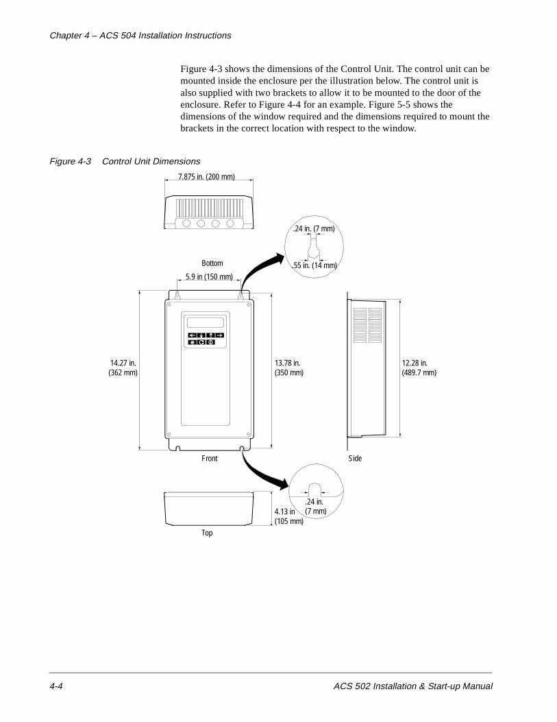
Chapter 4 – ACS 504 Installation Instructions
4-4 ACS 502 Installation & Start-up Manual
Figure 4-3 shows the dimensions of the Control Unit. The control unit can be mounted inside the enclosure per the illustration below. The control unit is also supplied with two brackets to allow it to be mounted to the door of the enclosure. Refer to Figure 4-4 for an example. Figure 5-5 shows the dimensions of the window required and the dimensions required to mount the brackets in the correct location with respect to the window.
Figure 4-3 Control Unit Dimensions
Front
Top
Side
.24 in.4.13 in
.24 in. (7 mm)
14.27 in. 12.28 in.
.55 in. (14 mm)5.9 in (150 mm)
7.875 in. (200 mm)
13.78 in.
Bottom
(489.7 mm)
(105 mm)(7 mm)
(350 mm)(362 mm)

Chapter 4 – ACS 504 Installation Instructions
ACS 502 Installation & Start-up Manual 4-5
Figure 4-4 Example of Control Box Mounting
Figure 4-5 Mounting Bracket location in relation to window cut-out
Door Closed Door Open
AAAAAAAA AAAAAAAA
AAAAAAAAA
AAAAAA A
AAAAAAAAAAAAAA
contbox1.eps> contbox1.dxf
AAAAAAAAAAAAAAAAAAAAAAAAAAAAAAAAAAAAAAAAAAAAAAAAAAAAAAAAA
AAAAAAAAAAAAAAAAAAAAAAAAAAAAAAAAAAAAAAAAAAAAAAAAAAAAAAAA
AAAAAAA
AAAAAAA
AAAAAAAAAAAAAAAAAAAAAAAAAAAAAAAAAAAAAAAAAAAAAAAA
AAAAAAAAAAAAAAAAAAAAAAAAAAAAAAA
AAAAAAAAAAAAAAAAAAAAA AAAAAAAAAAAAAAAAAAA AAAAAAAAAAAA
AAA
AAAAAAAA
AAAAAAAAAAA
AAAAAAAAAAA
AAAAAAAAAAAAAAAAAAAAAA
View from inside door
Window3.877”w3.051”h2.549”
(64.75 mm)
1.814” (46.08 mm)
6.944” (176.38 mm)
2.876” (73.05 mm)
LeftBracket
RightBracket
14.26”(362 mm)
9.32” (237 mm)
Depth 3.9” (100 mm)from inside door

Chapter 4 – ACS 504 Installation Instructions
4-6 ACS 502 Installation & Start-up Manual
Table 4-3 shows power losses and cooling air volumes with free space requirements for ACS 504 Inverter Modules.
Table 4-3 ACS 504 Cooling Requirements
Drive Type
Losses Air Volumes Free Space Requirements Opening Areas
Watts Unit Volume Unit A1 A2 A3 A4 A5 A6 A7 Unit Inlet Outlet
ACS 504-050-4
1750 m3/hr 300 mm 150 100 50 100 - 150 400 cm2 600 800
CFM 177 in. 6 4 2 4 - 6 16 sq in. 93 124
ACS 504-060-4
& 060-6
2500 m3/hr 570 mm 150 100 50 100 - 150 400 cm2 800 1000
CFM 335 in. 6 4 2 4 - 6 16 sq in. 124 155
ACS 504-075-4
& 075-6
3000 m3/hr 570 mm 150 100 50 100 - 150 400 cm2 800 1000
CFM 335 in. 6 4 2 4 - 6 16 sq in. 124 155
ACS 504-100-4
3500 m3/hr 690 mm 150 - 50 100 50 150 400 cm2 1000 1500
CFM 406 in. 6 - 2 4 2 6 16 sq in. 155 233
ACS 504-125-4
& 100-6
4250 m3/hr 690 mm 150 - 50 100 50 150 400 cm2 1000 1500
CFM 406 in. 6 - 2 4 2 6 16 sq in. 155 233
ACS 504-150-4
5250 m3/hr 950 mm 150 - 50 100 50 150 400 cm2 1200 1800
CFM 559 in. 6 - 2 4 2 6 16 sq in. 186 279
ACS 504-200-4
& 125-6
6500 m3/hr 950 mm 150 - 50 100 50 150 400 cm2 1200 1800
CFM 559 in. 6 - 2 4 2 6 16 sq in. 186 279
ACS 504-250-4
8000 m3/hr 1350 mm 150 - 50 100 50 150 400 cm2 1400 2000
CFM 795 in. 6 - 2 4 2 6 16 sq in. 217 310
ACS 504-300-4 and
350-4& 150-6
10000 m3/hr 1350 mm 150 - 50 100 50 150 400 cm2 1400 2000
CFM 795 in. 6 - 2 4 2 6 16 sq in. 217 310
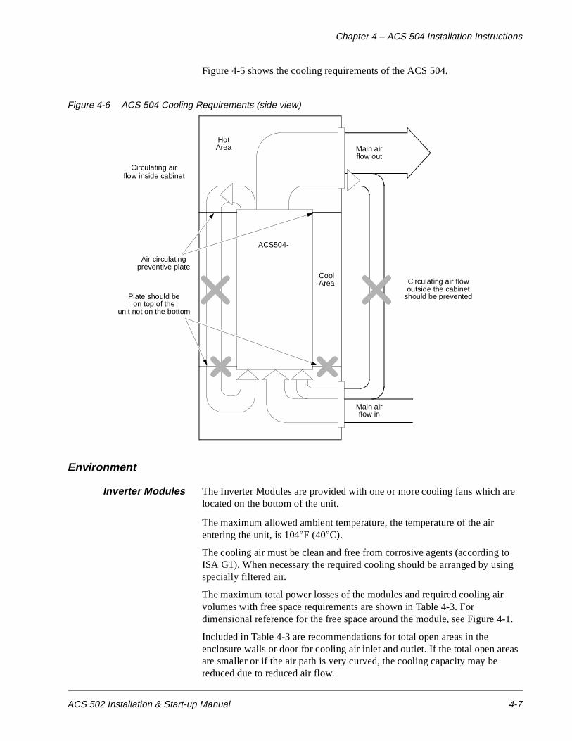
Chapter 4 – ACS 504 Installation Instructions
ACS 502 Installation & Start-up Manual 4-7
Figure 4-5 shows the cooling requirements of the ACS 504.
Figure 4-6 ACS 504 Cooling Requirements (side view)
Environment
Inverter Modules The Inverter Modules are provided with one or more cooling fans which are located on the bottom of the unit.
The maximum allowed ambient temperature, the temperature of the air entering the unit, is 104°F (40°C).
The cooling air must be clean and free from corrosive agents (according to ISA G1). When necessary the required cooling should be arranged by using specially filtered air.
The maximum total power losses of the modules and required cooling air volumes with free space requirements are shown in Table 4-3. For dimensional reference for the free space around the module, see Figure 4-1.
Included in Table 4-3 are recommendations for total open areas in the enclosure walls or door for cooling air inlet and outlet. If the total open areas are smaller or if the air path is very curved, the cooling capacity may be reduced due to reduced air flow.
ACS504-
CoolArea
HotArea Main air
flow out
Main airflow in
Circulating airflow inside cabinet
Air circulatingpreventive plate
Plate should beon top of the
unit not on the bottom
Circulating air flowoutside the cabinet
should be prevented

Chapter 4 – ACS 504 Installation Instructions
4-8 ACS 502 Installation & Start-up Manual
The losses shown in the preceding table occur when the output current is INSQ and input current is IINSQ. The temperature rise of the cooling air with these air volumes and losses is below 64°F (18°C).
Note: Dimension A7 is given with the assumption that the air exhaust is on top part of the door or side walls. This dimension may be reduced if the opening is on the roof of the cabinet.
GENERAL WARNING! When planning or inspecting the installation of ACS 504, pay special attention to the cooling air flow. Prevent the air from circulating from the outlet of the unit back to the inlet. Improper layout and inadequate channelling may lead to re-circulating air flow and excessive temperature rise within the enclosure. It may be necessary to install a horizontal baffle at the Inverter Module top level to keep the cool and warm air separate.
If the cooling air contains dust, clean the cooling surfaces of the unit regularly using compressed air and a brush. If there are filters at the air inlet of the enclosure, check their condition regularly and replace if needed.
If the cooling ability is reduced too much or if the ambient temperature exceeds 104°F (40°C), the thermal protection of the drive will operate causing an overtemperature warning and eventual tripping. The tripping temperature of the heatsink is 185°F (85°C). The drive can be started again when the temperature of the heatsink is below 167°F (75°C). (A faster way to start would be to disconnect the power, wait for the display to turn off, and power up again.)
The temperature of the heatsink can be read from the control panel display.
The temperature difference between the heatsink and ambient is an indication of the prevailing cooling conditions and can be utilized in preventive maintenance or in installation inspection. When the ACS 504 has been running at IR for more than an hour, the difference should be less than 77°F (25°C). When the ACS 504 has been running at IRSQ (fOUT at 60Hz) for more than an hour, the difference should be less than 86°F (30°C).
Note: When planning or inspecting the installation of your ACS 504, pay special attention to the cooling air flow. Do not let the air circulate from the outlet of the drive to the inlet. This is especially important when you install a module in an area where improper lay-out and inadequate channelling may lead to re-circulating air flow and excessive temperature rise within the cubicle.
Control Unit When planning the installation of the Control Unit in an enclosure, ensure that the temperature of the air surrounding the Control Unit does not exceed 122°F (50°C). Do not block the openings on the cover of the unit. Direct the warm exhaust air away from the Inverter Module so that it does not heat the Control Unit.
Chapter 4 – ACS 504 Installation Instructions
ACS 502 Installation & Start-up Manual 4-9
Power Connections
Input and Output PowerWiring
Four conductors (three phase plus a ground wire) are required for the input and output wiring. Use copper conductor rated for 167°F (75°C). Input and output conductors and branch circuit protection must be sized to local codes.
WARNING:
• Do not connect or disconnect input or output power wiring, or control wires, when power is applied.
• Never connect line voltage to drive output Terminals U2, V2, and W2 (T1 T2, T3).
• Do not make any voltage tolerance tests (Hi Pot or Meggar) on any part of the unit. Disconnect motor wires before taking any measurements in the motor or motor wires.
• Make sure that power factor correction capacitors are not connected between the drive and the motor.
Note that the 600 volt units are supplied with an AC input choke. This choke MUST be installed for the unit to operate properly.
Figure 4-6 and Figure 4-7 show the connections of the ACS 504.

Chapter 4 – ACS 504 Installation Instructions
4-10 ACS 502 Installation & Start-up Manual
Figure 4-7 ACS 504 Input and Output Power Connections
InputPower
OutputPower
Dynamic BrakeConnectionsCautionHigh Voltage!(Covered withprotective shield)
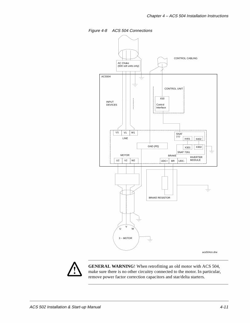
Chapter 4 – ACS 504 Installation Instructions
ACS 502 Installation & Start-up Manual 4-11
Figure 4-8 ACS 504 Connections
GENERAL WARNING ! When retrofitting an old motor with ACS 504, make sure there is no other circuitry connected to the motor. In particular, remove power factor correction capacitors and star/delta starters.
GND (PE)
U1 V1 W1
U2 V2 W2 UDC+ UDC-BR
AAAAAAAAAAAAAAAAAAAAAAAAAAAAAAAAAAAAAAAAAAAAAAAAAAAAAAAAAAAAAAAA
AAAAAAAAAAAAAAAAAAAAAAAAAAAAAAAAAAAAAAAAAAAA
AAAAAAAAAAAAAAAAAAAAAAAAAAAAAAAAAAAAAAAAAAAAAAAAAAAAAAAAAAAAAAAAAAAAAAAAAAAAAAAAAAAA
UV
W
ACS504
AAAAAAAAAAAA
AAAAAAAA
AAAAAAAA
AAAAAAAA
AAAAAAAA
AA
AAAAAAAAAAAAAAAAAA
AAAAAAAAAAAAAAAAAAAAAAAAAAAAAAAAAAAAAAAAAAAAAAAAAAAAAAAAAAA
AAAAAAAAAAAAA
AAAAAAAA
AAAAAAAAAAAAAAAAAAAAAAAAAAA
INPUTDEVICES Control
Interface
SNAT777
X401 X402
X50
SNAT 7261
X301 X302
BRAKE
AAAAAAAAAAAAA
AAAAAAAAAAAAA
AAAAAAAAAAAAA
AAAAAAAAAAAA
3 ~ MOTOR
BRAKE RESISTOR
LINE
MOTOR
CONTROL UNIT
CONTROL CABLING
INVERTERMODULE
acs504cn.drw
AC Choke(600 volt units only)

Chapter 4 – ACS 504 Installation Instructions
4-12 ACS 502 Installation & Start-up Manual
The terminal sizes and tightening torques of the power terminals are shown in Table 4-4, which also includes minimum current ratings and maximum I2t ratings for the input fuses to be used with the module (see page 3-4 for fuse types).
Check that the supply capacity is adequate for the drive (PR or PRSQ).
Table 4-4 ACS 504 Electrical Specifications
Precautions with MotorCable
Install the motor cable away from other cable routes. Avoid parallel runs with other cables.
WARNING! The brake control terminals carry a dangerous DC voltage (>600V). No device other than an ABB Drives dynamic braking device may be connected to the UDC+, BR, and UDC- terminals.
Connecting the ControlUnit to the Inverter
Module
The cable coming out of the Control Unit is to be connected to connector X604 on the Inverter Module. The connector must be secured with the thumb screws. The cable provided is 6 feet long, and should not be extended.
The yellow/green grounding wire that is connected to one of the PE terminals on the left side of the Inverter Module is also to be connected to the Control Unit Chassis (PE2).
Connecting the GroundFault Current Transformer
The ACS 504 is supplied with a current transformer (CT) to provide the ground fault protection. This CT should be installed on the input of the drive by running all three line wires through the CT (do not run the ground wire
Drive Type
Power terminals U1, V1, W1 and U2, V2, W2
Ground terminal (PE) Fuse Ratings
SizeTorque in
NmTorque in
lb-in.Size
Torque in Nm
Torque in lb-in.
A kA2s V
ACS 504-050-4 &ACS504-060-6 to ACS504-075-6
M10 30 – 44 260 – 380 M10 30 – 44 260 – 380 160 16 660
ACS 504-060-4 to ACS 504-075-4 & ACS 504-100-6
M10 30 – 44 260 – 380 M10 30 – 44 260 – 380 200 28 660
ACS504-125-6 M10 30 – 44 260 – 380 M10 30 – 44 260 – 380 250 28 660
ACS 504-100-4 & ACS 504-125-4 & ACS 504-150-6
M10 30 – 44 260 – 380 M10 30 – 44 260 – 380 400 105 660
ACS 504-150-4 & ACS 504-200-4
M12 50 – 75 435 – 650 M10 30 – 44 260 – 380 550 190 660
ACS 504-250-4 to ACS 504-350-4
M12 50 – 75 435 – 650 M10 30 – 44 260 – 380 700 405 660
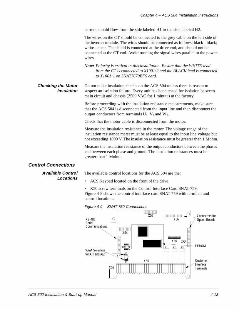
Chapter 4 – ACS 504 Installation Instructions
ACS 502 Installation & Start-up Manual 4-13
current should flow from the side labeled H1 to the side labeled H2.
The wires on the CT should be connected to the grey cable on the left side of the inverter module. The wires should be connected as follows: black - black; white - clear. The shield is connected at the drive end, and should not be connected at the CT end. Avoid running the signal wires parallel to the power wires.
Note: Polarity is critical in this installation. Ensure that the WHITE lead from the CT is connected to X1001:2 and the BLACK lead is connected to X1001:1 on SNAT7670EFS card.
Checking the MotorInsulation
Do not make insulation checks on the ACS 504 unless there is reason to suspect an isolation failure. Every unit has been tested for isolation between main circuit and chassis (2500 VAC for 1 minute) at the factory.
Before proceeding with the insulation resistance measurements, make sure that the ACS 504 is disconnected from the input line and then disconnect the output conductors from terminals U2, V2 and W2.
Check that the motor cable is disconnected from the motor.
Measure the insulation resistance in the motor. The voltage range of the insulation resistance meter must be at least equal to the input line voltage but not exceeding 1000 V. The insulation resistance must be greater than 1 Mohm.
Measure the insulation resistance of the output conductors between the phases and between each phase and ground. The insulation resistances must be greater than 1 Mohm.
Control Connections
Available ControlLocations
The available control locations for the ACS 504 are the:
• ACS Keypad located on the front of the drive.
• X50 screw terminals on the Control Interface Card SNAT-759.Figure 4-8 shows the control interface card SNAT-759 with terminal and control locations.
Figure 4-9 SNAT-759 Connections
V/mA Selectorsfor AI1 and AI2
X53
S1
X51
S3noterm
X50
K1 K2 K3
X55
X54
X56
1 2 3 4 5 6 7 8 9 10 11 12 13 14 15 16 17 18 19 20 21 22 23 24 25 26 27 28 29
Connectors forOption Boards
EPROM
CustomerInterfaceTerminals
S4
RS-485SerialCommunications
S2
I V
X57
X60
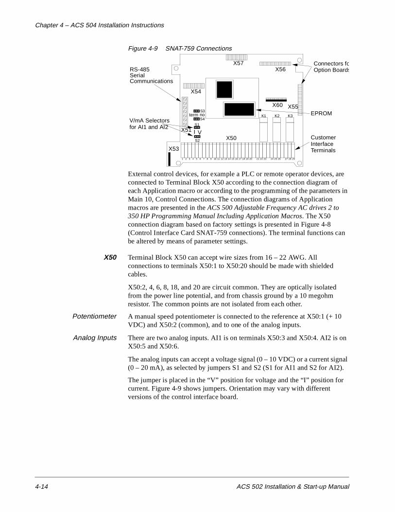
Chapter 4 – ACS 504 Installation Instructions
4-14 ACS 502 Installation & Start-up Manual
Figure 4-9 SNAT-759 Connections
External control devices, for example a PLC or remote operator devices, are connected to Terminal Block X50 according to the connection diagram of each Application macro or according to the programming of the parameters in Main 10, Control Connections. The connection diagrams of Application macros are presented in the ACS 500 Adjustable Frequency AC drives 2 to 350 HP Programming Manual Including Application Macros. The X50 connection diagram based on factory settings is presented in Figure 4-8 (Control Interface Card SNAT-759 connections). The terminal functions can be altered by means of parameter settings.
X50 Terminal Block X50 can accept wire sizes from 16 – 22 AWG. All connections to terminals X50:1 to X50:20 should be made with shielded cables.
X50:2, 4, 6, 8, 18, and 20 are circuit common. They are optically isolated from the power line potential, and from chassis ground by a 10 megohm resistor. The common points are not isolated from each other.
Potentiometer A manual speed potentiometer is connected to the reference at X50:1 (+ 10 VDC) and X50:2 (common), and to one of the analog inputs.
Analog Inputs There are two analog inputs. AI1 is on terminals X50:3 and X50:4. AI2 is on X50:5 and X50:6.
The analog inputs can accept a voltage signal (0 – 10 VDC) or a current signal (0 – 20 mA), as selected by jumpers S1 and S2 (S1 for AI1 and S2 for AI2).
The jumper is placed in the “V” position for voltage and the “I” position for current. Figure 4-9 shows jumpers. Orientation may vary with different versions of the control interface board.
V/mA Selectorsfor AI1 and AI2
X53
S1
X51
S3noterm
X50
K1 K2 K3
X55
X54
X56
1 2 3 4 5 6 7 8 9 10 11 12 13 14 15 16 17 18 19 20 21 22 23 24 25 26 27 28 29
Connectors foOption Boards
EPROM
CustomerInterfaceTerminals
S4
RS-485SerialCommunications
S2
I V
X57
X60

Chapter 4 – ACS 504 Installation Instructions
ACS 502 Installation & Start-up Manual 4-15
Digital (Relay) Outputs There are three relay outputs which are each Form C. Relay RO1 is on terminals X50:21, X50:22, and X50:23; Relay RO2 is on terminals X50:24, X50:25, and X50:26; Relay RO3 is on terminals X50:27, X50:28, and X50:29.
The first terminal for each relay is the normally closed terminal (NC), the second is the common, and the third is the normally open (NO).
Maximum Switching Voltage: 300 VDC / 250 VAC
Maximum Switching Current/Power: 8 A @ 24 VDC, 0.4 A @ 250 VDC, or 2000 VA @ 250 VAC
Maximum Continuous Current: 2 A rms
If the relay outputs are used to control inductive loads, such as the coils of relays or contactors, some form of noise supression must be provided at the load. This is to reduce the electrical noise that could interfere with the electronics in the drive, as well as increase the life of the contacts in the relay.
AC coils should be supressed with an MOV (metal oxide varistor) or a Series-Connected RC (resistor capacitor) network, as illustrated below:
MOV should be rated 120 VAC - 240 VAC for 115 VAC circuits, 240 VAC - 320 VAC for 230 VAC circuits, minimum 10 joules. Values for the RC Network vary, as they effect the opening and closing time. Contact the contactor manufacturer for recommended values.
DC coils should be supressed with a diode, although this is not required because of the small amount of noise generated by these type of circuits. If a diode is used, it should have a voltage rating greater than or equal to the supply voltage, and be connected as shown below:
X50MOV
X50
RC network
115 VAC
115 VAC
X50diode (24 VDC in this case)
24 VDC-
+
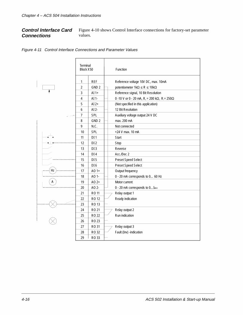
Chapter 4 – ACS 504 Installation Instructions
4-16 ACS 502 Installation & Start-up Manual
Control Interface Card Connections
Figure 4-10 shows Control Interface connections for factory-set parameter values.
Figure 4-11 Control Interface Connections and Parameter Values
Relay output 2
Run indication
1
2
3
4
5
6
7
8
9
10
11
12
13
14
15
16
17
18
19
20
21
22
23
24
25
26
27
28
29
REF
GND 2
AI 1+
AI 1-
AI 2+
AI 2-
SPL
GND 2
N.C.
SPL
DI 1
DI 2
DI 3
DI 4
DI 5
DI 6
AO 1+
AO 1-
AO 2+
AO 2-
RO 11
RO 12
RO 13
RO 21
RO 22
RO 23
RO 31
RO 32
RO 33
TerminalBlock X50 Function
Reference voltage 10V DC, max. 10mA
potentiometer 1kΩ ≤ R ≤ 10kΩReference signal, 10 Bit Resolution
0 -10 V or 0 - 20 mA, Rv = 200 kΩ, Ri = 250Ω(Not specified in this application)
12 Bit Resolution
Auxiliary voltage output 24 V DC
max. 200 mA
Not connected
+24 V max. 10 mA
Start
Stop
Reverse
Acc./Dec 2
Preset Speed Select
Preset Speed Select
Output frequency
0 - 20 mA corresponds to 0… 60 Hz
Motor current
0 - 20 mA corresponds to 0…IMAX
Relay output 1
Ready indication
Relay output 3
Fault (Inv) -indication
A AAAAAAAAAAAAAAAAAAAAAAAAAAAA
A AAAAAAAAAAAAAAAAAAAAAAAAAAAA
AA
AAAA
AAAAAAAA
AAAAAAAA
AAAAAAAA
AAAAAAAA
AAAAAA
AA
AAAA
AAAAAAAA
AAAAAAAA
AAAAAAAA
AAAAAAAA
AAAAAAAA
AAAAAAAA
AAAA
AA
AAAAAAAAAAAAAAAAAAAAAAAAAAAAAAAAAAAAAAAAAAAAAAAAAAAAAAAAAAAAAAAAAAAA
A
AAAAAAAAAAAAAAAAAAAAAAAAAAAAAAAAAAAAAAAAAAAAAAAAAAAAAAA
AAAAAAAAAA
AAAAAAAA
A AAAAAAAAAAAAAAAAAAAAAAAA
A AAAAAAAAAAAAAAAAAAAAAAAA
A AAAAAAAAAAAAAAAAAAAAAAA
AA
AAAA
AAAAAAAA
AAAAAAAA
AAAAAAAA
AAAAAAAA
AAAAAAAA
AAAA
A AAAAAAAAAAAAAAAAAAAAAAAA
AA AAAAAAAAAAAAAAAAAA
AA AAAAAAAAAAAAAAAAA
AA AAAAAAAAAAAAAAAAAA
AA AAAAAAAAAAAAAAAAAA
AA AAAAAAAAAAAAAAAAA
AA AAAAAAAAAAAAAAAAAA
A AAAAAAAA
A
AAAAAAAAAA
A AAAA
AAAAAAAA
AAAAAA
A AAAAAAAAAAAAAAAAAAAAAAAAAAAA
A
Hz
A AAAAAAAAAAAAAAAAAAAAAAAAAAAAA

ACS 502 Installation & Start-up Manual 5-1
Chapter 5 – Start-up Procedure
This chapter explains how to inspect the installation and how to start-up the ACS 502. Prerequisite information required for start-up was provided in Chapter 2 – Overview of the ACS 502/504.
Safety Precautions Before start-up, observe the following:
The components inside the converter module are at DC Bus potential (1.35 x VIN) when the ACS 502 is connected to supply voltage. This voltage is extremely dangerous and can cause death or serious injury.
When the supply voltage is disconnected from the input terminals U1, V1, W1 (L1, L2, L3), it will take about five minutes before the DC Bus capacitors are discharged to a safe voltage.
To ensure that the voltage level is safe, measure the voltage between positive (+) and negative (-) DC Bus Terminals UDC+ and UDC- (refer to Figure 4-7). Meter must be rated for 1000 VDC. Also measure between UDC+ and chassis ground.
The Control Interface Card and Option Cards are isolated from the main circuit, but dangerous voltages may be present at relay contact terminals. Always check for high voltage at Terminals X50:21 – 29 before working on the Control Interface or Option Cards.
WARNING! When the ACS 502 is connected to the line power, the Motor Terminals U2, V2, and W2 (T1, T2, T3) and the Brake Terminals UDC+, UDC-, and BR are live even if the motor is not running. Do not make any connections when the ACS 502 is connected to the line. Disconnect and lock out power to the drive before servicing the drive. Failure to disconnect power may cause death or serious injury.
Figure 5-1 shows the start-up checklist.

Chapter 5 – Start-up Procedure
5-2 ACS 502 Installation & Start-up Manual
Figure 5-1 Start-up Checklist
Installation Inspection Inspect the mechanical and electrical installation of the ACS 502 for compliance with the prevailing electrical installation regulations and codes.
Note: Do not connect the motor wires before proceeding with the Keypad Control Test, Motor Disconnected. Refer to Keypad Control Tests in this chapter.
After installation, inspect the following:
• Grounding of the ACS 502 and the motor.
• Supply and motor wires (selection of the wire size, connections).
• Control cables (connections, wire shields grounding, location as far as possible from the power wires).
• Quantity and quality of cooling air for the ACS 502.
• Verify that it is safe to run the motor.
• Connect the ACS 502 to supply voltage. Check that the voltage between L1 – L2, L2 – L3, and L1 – L3 (U1 – V1, U1 – W1, and V1 – W1) is VN ± 10%.
PREPARATION
SAFETY PRECAUTIONS- Read and follow safety instructions.
INSTALLATION INSPECTION
- Check for proper grounding.- Check supply wires and motor wires.- Check control wires.- Verify availability and quality of cooling air.
START-UP
START-UP DATA PARAMETERS- Check and complete the Start-Up Data
parameter values.
KEYPAD CONTROL TEST WITHOUT MOTOR- Check the operation of the ACS 502
without motor.
KEYPAD CONTROL TEST WITH MOTOR
- Check operation with motor connected.- Check external controls.
Chapter 5 – Start-up Procedure
ACS 502 Installation & Start-up Manual 5-3
Start-up Data Parameters
Power up the ACS 502. The display shows Operating Data Parameter 1 (Output Frequency). Before proceeding with the start-up, check and complete the Start-up Data Parameter values. Do not change parameters at this time except as described in the following steps.
While viewing Parameter 1 (Output Frequency) press and hold [ * ], then press [Right Arrow]. The display shows Parameter A (Language) in Setting mode.
A LANGUAGE Press [Up Arrow] or [Down Arrow] to select your preferred language. The ACS 502 displays all information in the language you select. Press [ * ] to confirm the selection and move to the next parameter. The available languages are: English, German, Italian, Spanish, Dutch, French, Danish, Finnish, and Swedish.
B APPLICATIONS Leave this in the FACTORY setting to perform the start-up procedure. If anything other than FACTORY displays, press [Up Arrow] or [Down Arrow] to change the parameter to FACTORY. Press [ * ] to confirm the selection and move to the next parameter.
C APPLIC. RESTORE This parameter restores all parameters of the current application to factory-set parameter values. Set this to YES by pressing [Up Arrow]. Press [ * ] to confirm the selection and move to the next parameter.
D SUPPLY VOLTAGE This parameter offers choices of 440, 460, 480, and 500 VAC for 480-volt units or 380, 400, and 415 VAC for 380-volt units.
Press [Up Arrow] or [Down Arrow] to select the voltage value matching line voltage providing power to your ACS 502. Press [ * ] to confirm the selection and move to the next parameter.
E USER DISPLAYSCALE
This parameter is used to set the scaling factor for Operating Data Parameter 2 (Speed). When set to 0, the speed display will show RPM. When set to 100 , the speed display will show %. When set to any other value from 0 – 10000, the display will show this value (minus slip unless slip compensation is ON) when the output frequency is at the frequency set by Start-up Data Parameter I (Motor Base Frequency).
Press [Up Arrow] or [Down Arrow] to set the desired value of the speed display. Press [ * ] to confirm the selection and move to the next parameter.
F MOTOR CURRENT-FLA
This parameter matches the ACS 502 to the rated motor current, adjustable between 0 and 1000 amps. The drive uses this parameter for motor overload protection and current (amperage) information displays.
Press [Up Arrow] or [Down Arrow] to select the current (amperage) value for your motor. Press [ * ] to confirm the selection and move to the next parameter.
Chapter 5 – Start-up Procedure
5-4 ACS 502 Installation & Start-up Manual
G MOTOR POWER This parameter matches the motor rated power, adjustable between 0.7 hp and 1340 hp. The drive uses this parameter for motor overload and kWh information displays. The left key switches the display between hp and kWh. To change the display, press and hold the left key for two seconds.
Press [Up Arrow] or [Down Arrow] to select the motor power value for your motor. Press [ * ] to confirm the selection and move to the next parameter.
H MOTOR POWERFACTOR
This parameter matches the motor power factor (at rated speed and load on sinusoidal power), adjustable between 0.10 and 1.0. The drive uses this parameter for motor torque and power information displays.
Press [Up Arrow] or [Down Arrow] to select the motor power factor value for your motor. Press [ * ] to confirm the selection and move to the next parameter.
I MOTOR BASEFREQUENCY
This parameter is used to set the designed frequency of the motor, adjustable from 30 Hz to 500 Hz in 10 Hz increments. Changing this value will automatically set the Field Weakening Point (FWP) to the same value.
Press [Up Arrow] or [Down Arrow] to select the base frequency value for your motor. Press [ * ] to confirm the selection and move to the next parameter.
J MOTOR BASE R.P.M. This parameter is used to set the nameplate speed of the motor and is adjustable from 200 to the maximum 2 pole motor speed based on Start-up Data Parameter I (Motor Base Frequency).
Press [Up Arrow] or [Down Arrow] to set the motor nameplate speed value for your motor. Press [ * ] to confirm the selection and move to the next parameter.
K MOTOR NOM.VOLTAGE
The default is 460 V for 480-volt units and 380 V for 380-volt units. Changing this parameter automatically changes the Maximum Output Voltage.
Press [Up Arrow] or [Down Arrow] to select the motor rated voltage for your motor. Press [ * ] to confirm the selection and return to Operating Data Parameter 1 (Output Frequency).
Keypad Control Tests
Motor Disconnectedfrom the ACS 502
After setting the Start-up Data parameters, test the drive as follows:
1. Disconnect and lock out power from the ACS 502. Wait at least five minutes after disconnecting power. Verify that the DC Bus voltage is at a safe level by measuring the voltage between positive (+) and negative (-) on Brake Terminals UDC+ and UDC-. Check for zero volts at Terminals X50:21 – 29 before continuing.
2. Disconnect the motor from the ACS 502.
3. Power up the ACS 502.
4. Press [Start/Stop] to issue a start command. The Run Status indicator on the LCD Display displays the Start (I) symbol.
Chapter 5 – Start-up Procedure
ACS 502 Installation & Start-up Manual 5-5
5. Press [ * ] to enter setting mode. Press [Up Arrow] until the frequency display shows 60 Hz, then press [ * ] to enter the value.
6. Press [Up Arrow] or [Down Arrow] to scroll through and check the Operating Data parameters. Check that Operating Data Parameter 7 (Output Voltage) is equal to the input voltage. Verify that Operating Data Parameter B (Motor Current) is less than 3% of the drive rated current (IR).
If the drive operates according to these steps, disconnect and lock out power to the ACS 502 to prepare for the next test.
WARNING! Wait at least five minutes after disconnecting power from the drive before you attempt to service the drive. Bus capacitors in the intermediate DC circuit must discharge before servicing the drive. Check for zero volts at Terminals TB1:21 – 29, UDC+, and UDC-. Your measuring meter must be rated for 1000 VDC. Failure to check voltages may result in death or serious injury.
If the drive does not operate according to these steps, refer to Chapter 6 – Fault Tracing in this manual for additional information.
Motor Connectedto the ACS 502
After successfully testing the drive with the motor disconnected, continue testing the drive as follows:
1. Disconnect and lock out power from the ACS 502. Check for zero volts at Terminals X50:21 – 29 and X2:(+) and (-) before continuing.
If a Bypass option is supplied, set the Drive Switch to NORMAL and the Bypass Switch to NORMAL.
2. Connect the motor to the ACS 502.
3. Power up the ACS 502.
4. Set Operating Data Parameter 10 (Keypad Ref 1) to 0.5 Hz.
CAUTION: Check motor rotation direction as soon as the motor begins to move. If motor rotation direction is critical and the motor does not run in the direction indicated by the Rotation Direction indicator on the ACS 502 LCD Display:• Shut down the drive.• Disconnect and lock out power to the drive.• Wait five minutes.• Check for zero volts at Terminals UDC+ and UDC-. When the drive has reached zero volts, swap any two motor output wires at the Output Terminals. Incorrect motor rotation direction may cause equipment damage.
5. Press [Start/Stop] to issue a start command. The Run Status indicator on the LCD Display displays the Start (I) symbol.
Chapter 5 – Start-up Procedure
5-6 ACS 502 Installation & Start-up Manual
6. Check the monitored values of Operating Data Parameters 1 – 8 for normal drive and motor operation.
7. Return to Operating Data Parameter 1 (Output Frequency).
8. Slowly increase the frequency value of Parameter 1. Verify that motor speed varies as frequency varies.
9. Increase the Parameter 1 frequency value to 60 Hz and return to Display mode.
10. Measure the output current in all three phases. The current should be balanced, and should not exceed the motor or drive rating.
11. If a Bypass option is supplied, check the motor rotation in bypass. Set the Bypass switch to BYPASS, then to TEST. If the motor turns in the wrong direction, swap any two input power wires.
If the drive operates according to these steps, your ACS 502 is ready to use with preset or modified macro adjustments.
If the drive does not operate according to these steps, refer to Chapter 6 – Fault Tracing in this manual.
Note: If you plan to use an external control device for your drive, you must wire the control to the drive according to the wiring scheme of the macro you select. If the 115 VAC control transformer is supplied, the Option Pack macro must be selected. Refer to Chapter 3 – Installation Instructions in this manual for more information on specific external control wiring schemes.
Refer to the Chapter 2 – Overview of the ACS 502/504, Control Panel Operation for more information on accessing and changing parameters.
Keypad Control vs.External Control
The ACS 502 can be controlled from two external control locations or from the Control Panel keypad. Refer to the ACS 500 Adjustable Frequency AC Drives 2 to 350 HP Programming Manual Including Application Macros, Chapter 3 – Control Operations, for additional information. The selection between KEYPAD and EXTERNAL is made through Operating Data Parameter 9 (Control Location).
KEYPAD R1 is a direct frequency reference, set by Operating Data Parameter 10 (Keypad Ref 1). KEYPAD PI goes through an application block, where it can be manipulated when the PI-controller is selected, set by Operating Data Parameter 11 (Keypad PI (REF 2)). Refer to the ACS 500 Adjustable Frequency AC Drives 2 to 350 HP Programming Manual Including Application Macros, Chapter 3 – Control Operations, for additional information.
EXTERNAL selection will cause the ACS 502 to follow commands connected to X50 (or TB1), such as a manual speed pot, HOA switch, Automatic Start, and Speed Signals, etc.
Chapter 5 – Start-up Procedure
ACS 502 Installation & Start-up Manual 5-7
Default Drive Parameters
Now that you have tested and started the drive using the Factory macro settings, check the Factory macro default drive parameters. Refer to the ACS 500 Adjustable Frequency AC Drives 2 to 350 HP Programming Manual Including Application Macros for additional information about Factory macro default settings.
ACS 502 external control wiring schemes vary according to the macro you choose and the parameter values you change. If you plan to change the ACS 502 macros or parameter values, and if you plan to use an external control device, refer to the ACS 500 Adjustable Frequency AC Drives 2 to 350 HP Programming Manual Including Application Macros for information on control wiring, application macros, and modifying macro parameters.
To complete the start-up, select the appropriate application macro, and make any necessary parameter changes. Connect all external wiring based on the configuration selected, and test all external interfacing.
Customizing Application Macro Parameters
At some point during the installation of your ACS 502 you may select one of the pre-set application macros closely suited to your application. You select application macros from Start-up Data Parameter B (Applications). You also may need to modify the macro to custom-fit your application. For example, if you select the Factory macro for your application, the Factory macro default for Start-up Data Parameter D (Supply Voltage) is 480 V. If your supply voltage is 460 V, you need to change this parameter in the macro accordingly.
To customize the macro for your application you must change certain parameter values. In each macro, certain parameters are more likely to be changed than other parameters, but the application determines which parameters, and in which macro, changes will be required.
Note: If you plan to use an external control device for your drive, you must wire the control to the drive according to the wiring scheme of the macro you select. Refer to the ACS 500 Adjustable Frequency AC Drives 2 to 350 HP Programming Manual Including Application Macros for more information on specific macro external control wiring schemes.
Refer to the ACS 500 Adjustable Frequency AC Drives 2 to 350 HP Programming Manual Including Application Macros for more information on accessing and changing parameters.
Note: If you use RUN ENABLE Digital Input from the screw terminals, the keypad’s START/STOP function becomes disabled until a run enable signal is present.
Note: The direction is fixed in FORWARD by Parameter 10.1.3 (Loc/Ext Direction) in the factory default settings for safety purposes. If the application requires reversing, change Parameter 10.1.3 accordingly. If reversing is not required, the digital input programmed for Direction can be reprogrammed for another function.
Chapter 5 – Start-up Procedure
5-8 ACS 502 Installation & Start-up Manual
Password Protection (Parameter Lock)
Parameter Lock prevents unauthorized persons from altering the parameters. When Parameter Lock is active the Setting mode cannot be selected and ACS 502 parameters can not be changed. The ACS 502 Parameter Lock can be controlled with the Keypad (Operating Data Parameter 20 (Parameter Lock)) or a digital input. Parameter 10.4.3 (Param. Lock Sel) (Keypad, DI1 – DI6) selects the control location. To activate the Parameter Lock, set operating Data Parameter 20 (Parameter Lock) to LOCKED xxx if the control location is the Keypad or activate the selected digital input if the control location is a DI setting.
The Parameter Lock control location is indicated in Operating Data Parameter 20 (Parameter Lock). Characters xxx after the parameter value (OPEN xxx, LOCKED xxx ) indicate that the current control location is Keypad.
To open the Parameter Lock, you must enter the correct combination. The combination for all ACS 502 units is 358. When viewing Parameter Lock, enter setting mode and set the xxx to 358. Press [ * ] to open the Parameter Lock. Refer to the ACS 500 Adjustable Frequency AC Drives 2 to 350 HP Programming Manual Including Application Macros, Chapter 3 – Control Operations, for detailed setting instructions.
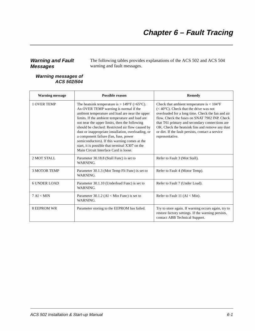
ACS 502 Installation & Start-up Manual 6-1
Chapter 6 – Fault Tracing
Warning and Fault Messages
The following tables provides explanations of the ACS 502 and ACS 504 warning and fault messages.
Warning messages ofACS 502/504
Warning message Possible reason Remedy
1 OVER TEMP The heatsink temperature is > 149°F (>65°C). An OVER TEMP warning is normal if the ambient temperature and load are near the upper limits. If the ambient temperature and load are not near the upper limits, then the following should be checked: Restricted air flow caused by dust or inappropriate installation, overloading, or a component failure (fan, fuse, power semiconductors). If this warning comes at the start, it is possible that terminal X307 on the Main Circuit Interface Card is loose.
Check that ambient temperature is < 104°F (< 40°C). Check that the drive was not overloaded for a long time. Check the fan and air flow. Check the fuses on SNAT 7902 INP. Check that T61 primary and secondary connections are OK. Check the heatsink fins and remove any dust or dirt. If the fault persists, contact a service representative.
2 MOT STALL Parameter 30.18.8 (Stall Func) is set to WARNING.
Refer to Fault 3 (Mot Stall).
3 MOTOR TEMP Parameter 30.1.3 (Mot Temp Flt Func) is set to WARNING.
Refer to Fault 4 (Motor Temp).
6 UNDER LOAD Parameter 30.1.10 (Underload Func) is set to WARNING.
Refer to Fault 7 (Under Load).
7 AI < MIN Parameter 30.1.2 (AI < Min Func) is set to WARNING.
Refer to Fault 11 (AI < Min).
8 EEPROM WR Parameter storing to the EEPROM has failed. Try to store again. If warning occurs again, try to restore factory settings. If the warning persists, contact ABB Technical Support.

Chapter 6 – Fault Tracing
6-2 ACS 502 Installation & Start-up Manual
Fault messages ofACS 502/504
Fault message Possible reason Remedy
1 START/STOP The start/stop reference from Control Interface Card is different from the start/stop state of the Motor Control Card.
Check the connection between Control Interface and Motor Control Cards. If the fault persists, contact ABB Technical Support.
2 OVER TEMP The heatsink temperature has been above 185°F (85°C) and has not fallen below 167°F (75°C). Restricted air flow caused by dust or inappropriate installation; overloading or a component failure (fan, power semiconductors). If the display shows a negative temperature, when the ambient (and heatsink) is obviously warmer, the thermostat S1 has probably opened (due to Rectifier bridge overtemperature). If this fault appears at start, it is possible that terminal X307 on Main Circuit Interface Card is loose.
Check that ambient temperature is < 104°F (< 40°C). Check that the drive was not overloaded for too long. Check the fan and air flow. Check the fuses on SNAT 7902 INP. Check that T61 primary and secondary connections are OK. Check heatsink fins, remove any dust or dirt. If the fault persists, contact a service representative. If the temperature display was negative, check the line fuses.
3 MOT STALL The ACS 502/504 has determined that the motor is operating in the stall region. Refer to Parameter 30.1.10 (Stall Time/Freq). The motor is not turning because of increased load torque. Motor may be too small for the application.
Remove mechanical problem causing increased load torque. If the motor shaft is rotating and the motor is not overheating, increase stall limit parameters. Check dimensioning, use larger drive and motor if necessary.
4 MOTOR TEMP The ACS 502/504 has determined that there is a high probability that the motor is overheated. Because the temperature rise is calculated from the motor current and not measured directly, the motor may be within temperature rise specification.
Check the motor temperature. If it is within temperature rise specification, increase Parameter 30.1.5 (Motor Load Curve) and/or Parameter 30.1.4 (Motor Therm Time) and restart. If the motor temperature is above rated temperature, improve motor cooling or resize the motor.
7 UNDER LOAD The motor load has dropped below the supervision limit set by Parameters 30.1.12 and 30.1.13.
Remove mechanical problem causing underload. Check motor load cycle and increase Parameter 30.1.12 (Underload Time) or change Parameter 30.1.13 (Underload Curve).
8 OVERCURR1 The output current instantaneous value has exceeded 375% of IN. Too short acceleration time relative to load inertia is the most common cause of an overcurrent trip. Also sudden shocks in the load torque may cause this trip. If the field weakening point is set too low or if there is too much IR-compensation, an overcurrent trip may follow. An oversized motor, a short circuit, or other hardware failure in the motor, motor cable, or in the drive itself may also cause this trip.
Check the load torque conditions and accelerating time. Make sure that there is no short circuit or ground fault in the motor circuit. See that there is no other load than the motor (especially capacitors) connected to the power output.
8 OVERCURR3 This trip originates from the supervisory circuits on the gate pulse channels on the Main Circuit Interface Card. An undervoltage at any of the gate pulse channels’ auxiliary +/- 15 V supply will cause this trip.
If the fault persists after resetting, it is most probably due to undervoltage at a pulse channel. Replace the Main Circuit Interface Card.If the fault persists after starting the drive once, contact ABB Service. Do not try to restart the drive several times, since this may lead to other hardware failures.

Chapter 6 – Fault Tracing
ACS 502 Installation & Start-up Manual 6-3
9 OVER VOLT DC bus voltage has exceeded 130% nominal voltage. Most common cause for this is overvoltage (static or transient) in the input line. Overvoltage can also result, when the motor runs as a generator in drives where the load inertia is extremely high and the deceleration time is set low.
Check the input line for static or transient overvoltages, e.g., generating loads or large power factor correction capacitors upstream.Use longer deceleration time or use coasting stop function if it is compatible with the application. If short deceleration time is needed, use Dynamic Braking Device.
10 UNDER V 1 DC bus voltage has gone below 60% of the nominal voltage. Most common reason for low voltage trip is failure in the input line, e.g., loss of one phase due to a fuse clearance. A sudden load spike or vibrations in the load may also cause this trip. Internal failure in the ACS 502/504 can cause this trip.
Check input line fuses and supply. If they are OK, an internal failure has occurred. Contact ABB Technical Support.
11 AI < MIN Analogue input less than the minimum as set by Parameters 10.5.1 and 10.5.5.
Input reference has failed or control wire is broken. Check the reference circuit.
16 PWR RNGE Power range programming does not match after replacing the Control Interface or the Main Circuit Interface Card.
Check the Matching Card which is on top of the Main Circuit Interface Card. Check that the start-up data is given accordingly for the new Control Interface Card. Remove power, wait one minute, then restore power. If the fault persists, contact ABB Technical support.
19 IN COMMS Failure in serial communication within the Control Interface and/or Motor Control Cards.
Check the cabling between the Control Interface and the Motor Control Cards. If the fault persists, contact ABB Technical Support.
20 CON INT This fault is related to components in the Control Interface Card.
Remove power, wait one minute, then restore power. If the problem persists, call ABB Technical Support.
21 MOT CONTX This fault is related to components in the Motor Control Card or in the Converter Module.
The number replacing the X in the fault message conveys the following information:1 = U2 phase current measurement problem 2 = V2 phase current measurement problem 3 = DC-voltage measurement problem 4 = Serial communication problem 5 = Power supply problem on SNAT 777 6 = Too high ripple content in DC-voltage, possibly caused by an input line fuse failure or phase loss/unbalance. Check these areas. Also make sure that the load is not vibrating. If the fault persists, check the Input Protection Card and/or rectifier modules. For faults 1 – 5, remove power, wait one minute, then restore power. If the problem persists, call ABB Technical Support. Record the specific fault code (X), you may be asked for it.
22 PAR REST Parameter restoring error. Parameter checksum does not match.
Reset fault display. (The display is reset allowing the scrolling of parameters, but the fault is not reset.) Check all parameter settings or reset the factory settings. Remove power, wait one minute, then restore power and check that the fault has disappeared.
Fault message Possible reason Remedy
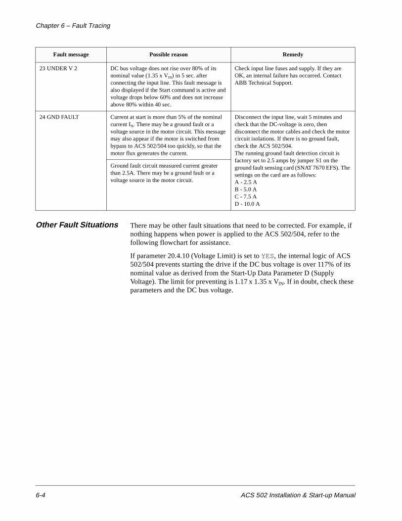
Chapter 6 – Fault Tracing
6-4 ACS 502 Installation & Start-up Manual
Other Fault Situations There may be other fault situations that need to be corrected. For example, if nothing happens when power is applied to the ACS 502/504, refer to the following flowchart for assistance.
If parameter 20.4.10 (Voltage Limit) is set to YES, the internal logic of ACS 502/504 prevents starting the drive if the DC bus voltage is over 117% of its nominal value as derived from the Start-Up Data Parameter D (Supply Voltage). The limit for preventing is 1.17 x 1.35 x VIN. If in doubt, check these parameters and the DC bus voltage.
23 UNDER V 2 DC bus voltage does not rise over 80% of its nominal value (1.35 x VIN) in 5 sec. after connecting the input line. This fault message is also displayed if the Start command is active and voltage drops below 60% and does not increase above 80% within 40 sec.
Check input line fuses and supply. If they are OK, an internal failure has occurred. Contact ABB Technical Support.
24 GND FAULT Current at start is more than 5% of the nominal current IN. There may be a ground fault or a voltage source in the motor circuit. This message may also appear if the motor is switched from bypass to ACS 502/504 too quickly, so that the motor flux generates the current.
Disconnect the input line, wait 5 minutes and check that the DC-voltage is zero, then disconnect the motor cables and check the motor circuit isolations. If there is no ground fault, check the ACS 502/504.The running ground fault detection circuit is factory set to 2.5 amps by jumper S1 on the ground fault sensing card (SNAT 7670 EFS). The settings on the card are as follows:A - 2.5 AB - 5.0 AC - 7.5 AD - 10.0 A
Ground fault circuit measured current greater than 2.5A. There may be a ground fault or a voltage source in the motor circuit.
Fault message Possible reason Remedy
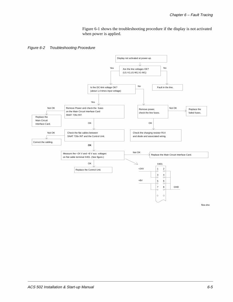
Chapter 6 – Fault Tracing
ACS 502 Installation & Start-up Manual 6-5
Figure 6-1 shows the troubleshooting procedure if the display is not activated when power is applied.
Figure 6-2 Troubleshooting Procedure
OK
1 2
3 4
5 6
7 8
+24V
+8V
GND
X401
Display not activated at power-up.
Are the line voltages OK?
(U1-V1,U1-W1,V1-W1)
Yes No
Fault in the line.Is the DC-link voltage OK?
(about 1,4 times input voltage)
Yes
No
Remove Power and check the fuses
on the Main Circuit Interface Card
SNAT 726x INT.
OK
Remove power,
check the line fuses.
OK
Check the charging resistor R14
and diode and associated wiring.
Check the flat cables between
SNAT 726x INT and the Control Unit.
Measure the +24 V and +8 V aux. voltages
on flat cable terminal X401. (See figure.)
Replace the Control Unit.
Replace the Main Circuit Interface Card.
Not OK
OK
Not OK
OK
Replace the
failed fuses.
Not OK
Replace the
Main Circuit
Interface Card.
Not OK
Correct the cabling.
flow.drw

Chapter 6 – Fault Tracing
6-6 ACS 502 Installation & Start-up Manual
This page intentionally left blank.

ACS 502 Installation & Start-up Manual A-1
Appendix A – ACS 502/504 Technical Data
Input Power Voltage: 440/460/480/500 VAC ± 10% for 480 VAC units
380/400/415 VAC ± 10% for 380 VAC units
Frequency: 48 – 63 Hz
Displacement Power Factor: > 0.98
Line Imbalance: ± 3% of VR
Output Power Voltage: 0 – VN, three-phase (full voltage at field weakening point)
Frequency: 0 – 120 Hz
Frequency Resolution: 0.01 Hz
Continuous Current (constant torque): 1.0 x IR
Continuous Current (variable torque): 1.0 x IRSQ
Maximum Current (1 min/every 10 min): 1.5 x IR
Short Time Overload (2 sec/every 1 min): 2.0 x IR
Overcurrent Trip: 3.75 x IN instantaneous, 2.65 x IN (RMS)
Field Weakening Point: 30 – 180 Hz
Continuous Loadability of Motor: 100% at rated speed (for F class motor)
Modulation Frequency: 3 kHz
Analog Inputs Two programmable analog inputs.
Current Reference: 0 – 20 mA, RI = 250 ohms
• Minimum: 0 mA / 4 mA / 0 – 20 mA
• Maximum: 0 – 20 mA
Voltage Reference: 0 - 10 V, RI = 200K ohms
• Minimum: 0 V / 2 V / 0 – 10 V
• Maximum: 0 – 10 V
Potentiometer: 1K – 10K ohms
Potentiometer Reference Voltage: 10 V, 10 mA
Resolution: AI1 = 10 Bit; AI2 = 12 Bit
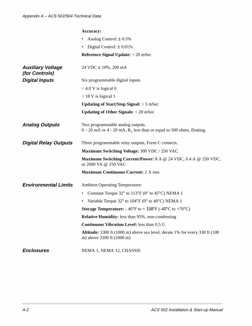
Appendix A – ACS 502/504 Technical Data
A-2 ACS 502 Installation & Start-up Manual
Accuracy:
• Analog Control: ± 0.5%
• Digital Control: ± 0.01%
Reference Signal Update: < 20 mSec
Auxiliary Voltage (for Controls)
24 VDC ± 10%, 200 mA
Digital Inputs Six programmable digital inputs.
< 4.0 V is logical 0
> 18 V is logical 1
Updating of Start/Stop Signal: < 5 mSec
Updating of Other Signals: < 20 mSec
Analog Outputs Two programmable analog outputs.0 – 20 mA or 4 - 20 mA, RL less than or equal to 500 ohms, floating.
Digital Relay Outputs Three programmable relay outputs, Form C contacts.
Maximum Switching Voltage: 300 VDC / 250 VAC
Maximum Switching Current/Power: 8 A @ 24 VDC, 0.4 A @ 250 VDC, or 2000 VA @ 250 VAC
Maximum Continuous Current: 2 A rms
Environmental Limits Ambient Operating Temperature:
• Constant Torque 32° to 113°F (0° to 45°C) NEMA 1
• Variable Torque 32° to 104°F (0° to 40°C) NEMA 1
Storage Temperature: - 40°F to + 158°F (-40°C to +70°C)
Relative Humidity: less than 95%, non-condensing
Continuous Vibration Level: less than 0.5 G
Altitude: 3300 ft (1000 m) above sea level, derate 1% for every 330 ft (100 m) above 3300 ft (1000 m)
Enclosures NEMA 1, NEMA 12, CHASSIS

ACS 502 Installation & Start-up Manual G-1
Glossary
Analog Input (AI) An Analog Input is an input to the ACS 502/504 for a user-supplied DC signal. The signal may be a speed reference or a process feedback. This signal can be from:
• Manual speed pot
• DC voltage (0 to 10 VDC)
• DC current (0 to 20 mADC)
Analog inputs on the ACS 502/504 Keypad Display are abbreviated AI.
Converter The ACS 502/504 series adjustable frequency drive (AFD) uses a three-phase diode bridge to convert the applied AC line voltage to rectified DC.
DC Bus The DC Bus is comprised of the:
• DC potential source (internal rectifier bridge or external source),
• DC link inductor (connecting the DC bus capacitors to the DC potential source), and
• DC bus capacitors that, together with the DC link inductor, provide filtration of the DC source potential and provide some buffering between the DC source and the power inverter section.
The DC Bus voltage is 1.35 x Supply Voltage (VIN).
Default A default is a pre-programmed value for a parameter. When you first install and start your ACS 502/504 drive, all application macro parameter values appearing on the Keypad Display are default settings. You may change these default settings in the process of customizing your drive for your particular drive application.
Digital Input (DI) The Digital Inputs (DI) receive bistable (two-state On-Off) control signals from the outside world. An example of such would be a two-position Start-Stop selector switch. Digital inputs on the ACS 502/504 Keypad Display are abbreviated DI.
EEPROM EEPROM is an acronym for Electrically Erasable Programmable Read Only Memory. The EEPROM is the non-volatile memory that stores all parameters, even when power is removed.
ESD ESD is an acronym for Electrostatic Discharge. ESD cautions indicate situations in which static electricity can damage circuit boards on the ACS 502/504 drive. Follow the precautions listed in the Safety section at the beginning of this manual when installing or removing circuit boards.

Glossary
G-2 ACS 502 Installation & Start-up Manual
Field Weakening Point This is the point at which the output voltage no longer increases as the output frequency is increased. Operation above this point results in reduced motor torque capability while the output kVA remains constant. Refer to Parameter 20.4.4 (Field Weak Point).
Group A Group is the second of three display levels in ACS 502/504 programming. Groups group parameters by their functionality, and provide access to them in the same way that Mains provide access to Groups. Groups appear within their respective Mains. For example, if you need to access Group 20.4 or Group 20.3, you must first select Main 20 using specific Keypad procedures. Refer to Chapter 2 – Overview of the ACS 502/504.
IGBT An IGBT is a fast switching power transistor. ACS 502/504 drives use these in the inverter section as part of the process of changing DC voltage to AC voltage.
I R This notation abbreviates the constant torque rated output current, in amperes, of an ACS 502/504.
I RSQ This notation abbreviates the rated variable drive output current, in amperes, of an ACS 502/504.
I N This notation abbreviates the current which the drive trips and on which settings are based.
Inverter The inverter changes DC power to AC power for application to the motor windings. Control of the inverter affords variable frequency and voltage to be applied to the motor for control of motor speed and direction.
IR Compensation IR Compensation is a parameter that provides the motor with extra torque at motor speeds between 0.1 Hz and the set Field Weakening Point. Refer to Parameter 20.4.4 (Field Weak Point) and Field Weakening Point in this glossary.
Joystick Control Joystick control allows you to use a joystick for external speed and direction drive control through analog input AI1. Refer to Parameter 10.2.2 (External Ref1 Sel).
Line Voltage Line voltage in this manual means the input voltage that provides power to the ACS 502/504. Line voltage is connected to the ACS 502/504 Terminals L1, L2, and L3. Refer to Start-up Data Parameter D (Supply Voltage). Refer to Supply Voltage in this glossary.
Living Zero The Living Zero function allows the ACS 502/504 to detect a loss of reference signal. Set Parameter 10.5.1 (Minimum AI1) to a value greater than 0.3 V/0.6 mA for a Living Zero function. You can then supervise the presence of a control signal by setting Parameter 30.1.2 (AI < Min Function) to WARNING or FAULT. A Warning or Fault message will then display if the analog input falls below the set minimum.

Glossary
ACS 502 Installation & Start-up Manual G-3
Macro A macro is a pre-programmed set of defaults for all of the parameters, which are typical for the specified application. When you select a macro from Start-up Data Parameter B (Applications), you select the macro that most closely defines the drive functions necessary for your particular application. After selecting the macro, you can modify or customize the macro to specifically conform to your application.
Refer to the ACS 500 Adjustable Frequency AC Drives 2 to 350 HP Programming Manual Including Application Macros for information on macro applications, functions, and parameter values.
Main A Main is the first of four display levels in the ACS 502/504 programming. Mains provide access to Groups in the same way that Groups provide access to Parameters. For example, to access Main 10 while viewing any of the 28 Operating Data Parameters, press [Right Arrow] on the Control Panel Keypad. From the Main 10 display, press [Up Arrow] to access Main 20, Main 30, and Main 40. Refer to Chapter 2 – Overview of the ACS 502/504.
Meggar Test A Meggar Test measures an insulation system's resistance. This test passes a low current, high voltage through a capacitor and measures the resistance of the insulation system. Meggar test results are usually expressed in megohms.
CAUTION: The ACS 502/504 must not be subjected to testing of this type as damage could result. Any wires connected to the ACS 502/504 MUST be disconnected from the ACS 502/504 before being subjected to this type of test.
Memory The ACS 502/504 memory provides computer storage for program data and instructions.
Multimeter A multimeter measures electric component functions and values such as voltage (volts), resistance (ohms), and current (amperes). Some multimeters also test diodes.
Operating Data Operating Data defines ACS 502/504 Parameters 1 (Output Frequency) through 28 (Act Value 2 (PFC)) located at the first of four display levels.
Many Operating Data parameters simply display information such as drive temperature and motor speed, and some parameter values can be changed according to drive application needs.
Parameter A Parameter is the last of four display levels in the ACS 502/504 programming. In most cases, Groups provide access to Parameters, and Parameters allow you to modify macros, change start-up settings, and monitor drive and motor functions. Refer to Chapter 2 – Overview of the ACS 502/504.
PR This notation abbreviates the rated constant torque output power rating of an ACS 502/504.
PRSQ This notation abbreviates the rated variable torque output power rating of an ACS 502/504.

Glossary
G-4 ACS 502 Installation & Start-up Manual
Rectifier A rectifier is a device that permits current flow in one direction and blocks the flow of current in the other direction. In today's technology, rectifiers are of the silicon diode type. The ACS 502/504 uses six rectifiers, configured into a three-phase bridge configuration, as the power converter section of the drive.
Slip Compensation Slip compensation is a feature in the ACS 502/504 that allows the drive to compensate for motor slip caused by increased load.
Start-up Data Start-up Data parameters allow you to set certain parameter values prior to starting the ACS 502/504. You set these parameters according to the language you want the drive to display (such as German, Spanish, or English), the supply voltage providing power to the drive, and so on. In most cases, these parameters are one-time settings made only during the drive installation process.
Start-up Data parameters are not accessed through the same display levels as Operating Data parameters, Main level, or Group level. Instead, you must first view Operating Data Parameter 1 (Output Frequency), press and hold [ * ] on the Control Panel Keypad, then press [Right Arrow]. Only this procedure accesses Start-up Data parameters on the ACS 502/504.
Supply Voltage Supply voltage in this manual means the input voltage that provides power to the ACS 502/504. Supply voltage is connected to ACS 502/504 Terminals L1, L2, and L3. Refer to Start-up Data Parameter D (Supply Voltage). Refer to Line Voltage and VIN in this glossary.
TR This notation abbreviates the rated output torque of the motor.
VIN This notation abbreviates the input voltage to the drive. Refer to Supply Voltage in this glossary.
VN This notation abbreviates the voltage for which the drive is programmed.
VR This notation abbreviates the rated input voltage, in volts, of an ACS 502/504.

ACS 502 Installation & Start-up Manual I-1
Index
Numerics
115 VAC auxiliary powerACS 502 connections 3-12
115 VAC startACS 502 connections 3-12
A
Ambient temperature for ACS 502 3-2Analog inputs
ACS 502 connections 3-10ACS 504 connections 4-14
Analog outputsACS 502 connections 3-11ACS 504 connections 4-14
APPLIC. RESTORE 5-3Application macros
customizing 5-7default settings 2-11overview 2-11
APPLICATIONS 5-3Audience, intended 1-2Auxiliary 24 VDC
ACS 502 connections 3-11
B
Braking, dynamic 3-8
C
Cautions, definition iiiControl connections for ACS 502
external control 3-8TB1 3-9
Control connections for ACS 504SNAT-759 4-13, 4-16X50 4-13
Control interface card, ESD warning ivControl panel
display 1-2, 2-8keys 1-2, 2-9LCD display illustration 2-8operation 2-8table of keypad functions 2-9using the keys 1-2
Conventions used in this manual 1-2Cooling requirements for ACS 502 3-1
D
DC bus capacitors ivDigital inputs
ACS 502 connections 3-11ACS 504 connections 4-14
Digital outputsACS 502 connections 3-11ACS 504 connections 4-15
Dimensions of ACS 502 3-2Dimensions of ACS 504 4-2Display contrast, adjusting 2-11Display indications 2-8Drive code, nameplate identification 2-1Dynamic braking 3-8
E
ESD warning ivExternal control 5-6
F
Fault messages 6-1Fault tracing 5-5Faults 6-4freeze/fire/smoke
ACS 502 connections 3-12
G
Ground lug sizes for ACS 502 3-5Group, defined 1-2
I
Input powerwire sizes for ACS 502 3-4wire sizes for ACS 504 4-9
K
Keypad controldefinition 5-6
Keypad functions 2-9Keys, control panel 1-2
Index
I-2 ACS 502 Installation & Start-up Manual
L
LANGUAGE 5-3Liability inf ormation 1-3
M
Macros, overview 2-11Main, defined 1-2MOTOR BASE FREQUENCY 5-4MOTOR BASE R.P.M. 5-4Motor control card
ESD warning ivMOTOR CURRENT -FLA 5-3MOTOR NOM. VOLTAGE 5-4MOTOR POWER 5-4MOTOR POWER FACTOR 5-4Motor rotation, direction 5-5
N
Nameplate, identification 2-1Notes, definition iii
O
Output powerACS 502 maximum wire lengths 3-5terminal connections from ACS 504 4-13
Output wiring for ACS 502 3-7Output wiring for ACS 504 4-9
P
Parameterdefined 1-2value changing example 2-10
Parameter lock 5-8Password protection 5-8Potentiometer
ACS 502 connections 3-10ACS 504 connections 4-14
Power requirement for ACS 502 3-2Pre-installation planning for ACS 502
environment 3-1mounting 3-2output wire length restrictions 3-5power wiring table 3-4
Pre-installation planning for ACS 504environment 4-6input wiring 4-9mounting 4-2, 4-3output wiring 4-9
Programming example 2-10Publications related to this manual 1-3
R
Relay outputsACS 502 connections 3-11ACS 504 connections 4-15
S
Safety instructionsgeneral iiigrounding for ACS 502 3-1warning symbols iii
Specifications A-1Start-up
default parameters 5-7inspection 5-2parameters 5-3safety precautions 5-1
Start-up data parameters 5-3SUPPLY VOLTAGE 5-3
T
Technical data A-1Terminal block, defined 1-3Tests
hi pot 3-6, 4-9Meggar 3-6, 4-9motor connected 5-5motor disconnected 5-4
Troubleshooting procedure 6-5Two-wire start
ACS 502 connections 3-12
U
USER DISPLAY SCALE 5-3

Index
ACS 502 Installation & Start-up Manual I-3
V
Voltage tolerance testshi pot warning 3-6, 4-9Meggar warning 3-6, 4-9
W
Warning messages 6-1Warranty information 1-3Wire sizes for ACS 502
power 3-4Wire sizes for ACS 504
power 4-9Wiring
control 5-6
X
X50ACS 504 connections 4-14

Index
I-4 ACS 502 Installation & Start-up Manual
This page intentionally left blank.


ABB Industrial Systems Inc.16250 West Glendale DriveNew Berlin, WI 53151Telephone: (414) 785-3416Fax: (414) 785-0397
ASEA BROWN BOVERI AC
S 50
2-04
FEF
FEC
TIV
E 8/
331/
95SU
PER
SED
ES 3
/1/9
4