acs ads airprep systems - schmidtabrasiveblasting.com · acs 250 acs 400 acs 750 acs 950 acs 1200...
TRANSCRIPT
AIRPREP SYSTEM OPERATION AND MAINTENANCE MANUAL
September 2017
SAVE THIS MANUAL AND MAKE AVAILABLE TO ALL USERS OF THIS EQUIPMENT!
Manual Part Number 7200-260
(Available for downloading from SchmidtAbrasiveBlasting.com)
Copyright © 2017 AXXIOM Manufacturing, Inc. 11927 S. Highway 6, Fresno, Texas 77545
800.231.2085 * 281.431.0581 * fax 281.431.1717
Website Visit us at www.SchmidtAbrasiveBlasting.com Manual
Copyright © 2017 Axxiom Manufacturing, Inc.
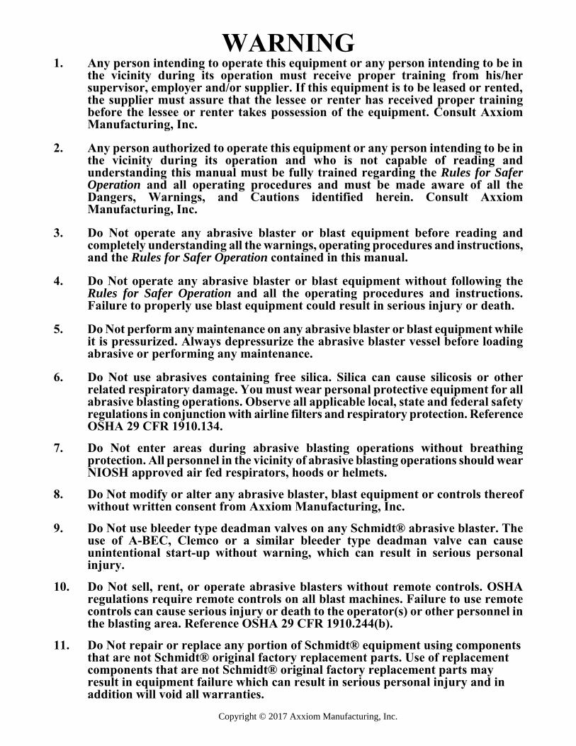
WARNING 1. Any person intending to operate this equipment or any person intending to be in
the vicinity during its operation must receive proper training from his/her supervisor, employer and/or supplier. If this equipment is to be leased or rented, the supplier must assure that the lessee or renter has received proper training before the lessee or renter takes possession of the equipment. Consult Axxiom Manufacturing, Inc.
2. Any person authorized to operate this equipment or any person intending to be in
the vicinity during its operation and who is not capable of reading and understanding this manual must be fully trained regarding the Rules for Safer Operation and all operating procedures and must be made aware of all the Dangers, Warnings, and Cautions identified herein. Consult Axxiom Manufacturing, Inc.
3. Do Not operate any abrasive blaster or blast equipment before reading and
completely understanding all the warnings, operating procedures and instructions, and the Rules for Safer Operation contained in this manual.
4. Do Not operate any abrasive blaster or blast equipment without following the
Rules for Safer Operation and all the operating procedures and instructions. Failure to properly use blast equipment could result in serious injury or death.
5. Do Not perform any maintenance on any abrasive blaster or blast equipment while
it is pressurized. Always depressurize the abrasive blaster vessel before loading abrasive or performing any maintenance.
6. Do Not use abrasives containing free silica. Silica can cause silicosis or other
related respiratory damage. You must wear personal protective equipment for all abrasive blasting operations. Observe all applicable local, state and federal safety regulations in conjunction with airline filters and respiratory protection. Reference OSHA 29 CFR 1910.134.
7. Do Not enter areas during abrasive blasting operations without breathing
protection. All personnel in the vicinity of abrasive blasting operations should wear NIOSH approved air fed respirators, hoods or helmets.
8. Do Not modify or alter any abrasive blaster, blast equipment or controls thereof
without written consent from Axxiom Manufacturing, Inc. 9. Do Not use bleeder type deadman valves on any Schmidt® abrasive blaster. The
use of A-BEC, Clemco or a similar bleeder type deadman valve can cause unintentional start-up without warning, which can result in serious personal injury.
10. Do Not sell, rent, or operate abrasive blasters without remote controls. OSHA
regulations require remote controls on all blast machines. Failure to use remote controls can cause serious injury or death to the operator(s) or other personnel in the blasting area. Reference OSHA 29 CFR 1910.244(b).
11. Do Not repair or replace any portion of Schmidt® equipment using components
that are not Schmidt® original factory replacement parts. Use of replacement components that are not Schmidt® original factory replacement parts may result in equipment failure which can result in serious personal injury and in addition will void all warranties.
i Copyright © 2017 Axxiom Manufacturing, Inc.
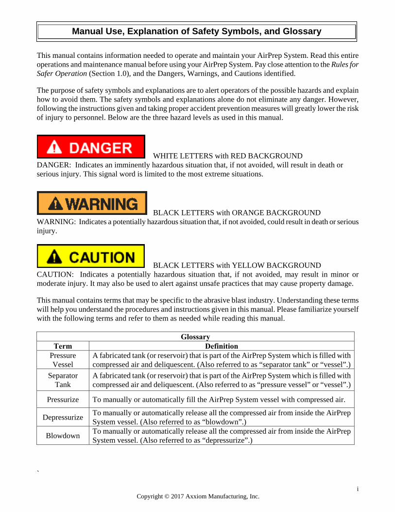
This manual contains information needed to operate and maintain your AirPrep System. Read this entire operations and maintenance manual before using your AirPrep System. Pay close attention to the Rules for Safer Operation (Section 1.0), and the Dangers, Warnings, and Cautions identified. The purpose of safety symbols and explanations are to alert operators of the possible hazards and explain how to avoid them. The safety symbols and explanations alone do not eliminate any danger. However, following the instructions given and taking proper accident prevention measures will greatly lower the risk of injury to personnel. Below are the three hazard levels as used in this manual.
WHITE LETTERS with RED BACKGROUND DANGER: Indicates an imminently hazardous situation that, if not avoided, will result in death or serious injury. This signal word is limited to the most extreme situations.
BLACK LETTERS with ORANGE BACKGROUND WARNING: Indicates a potentially hazardous situation that, if not avoided, could result in death or serious injury.
BLACK LETTERS with YELLOW BACKGROUND CAUTION: Indicates a potentially hazardous situation that, if not avoided, may result in minor or moderate injury. It may also be used to alert against unsafe practices that may cause property damage. This manual contains terms that may be specific to the abrasive blast industry. Understanding these terms will help you understand the procedures and instructions given in this manual. Please familiarize yourself with the following terms and refer to them as needed while reading this manual.
Glossary Term Definition
Pressure Vessel
A fabricated tank (or reservoir) that is part of the AirPrep System which is filled with compressed air and deliquescent. (Also referred to as “separator tank” or “vessel”.)
Separator Tank
A fabricated tank (or reservoir) that is part of the AirPrep System which is filled with compressed air and deliquescent. (Also referred to as “pressure vessel” or “vessel”.)
Pressurize To manually or automatically fill the AirPrep System vessel with compressed air.
Depressurize To manually or automatically release all the compressed air from inside the AirPrep System vessel. (Also referred to as “blowdown”.)
Blowdown To manually or automatically release all the compressed air from inside the AirPrep System vessel. (Also referred to as “depressurize”.)
`
Manual Use, Explanation of Safety Symbols, and Glossary
ii Copyright © 2017 Axxiom Manufacturing, Inc.
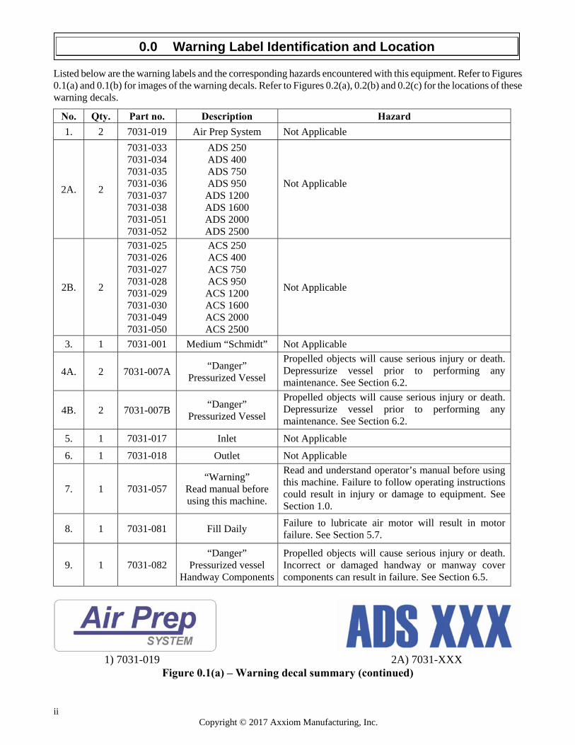
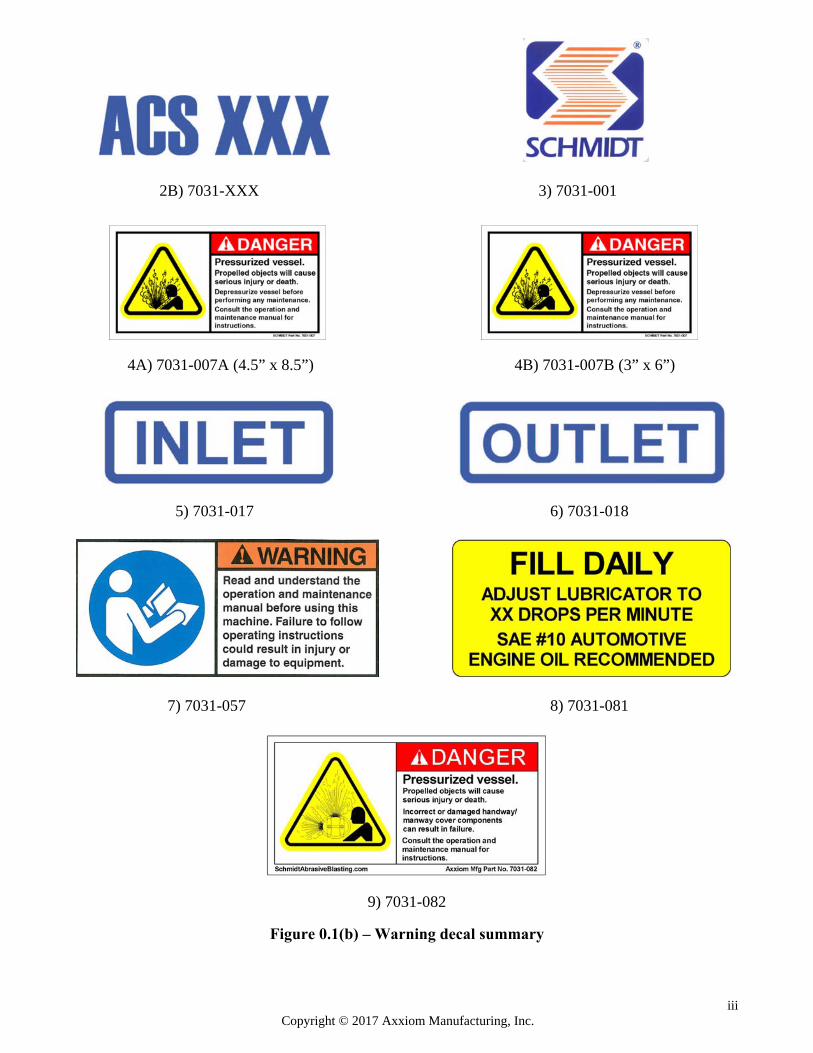
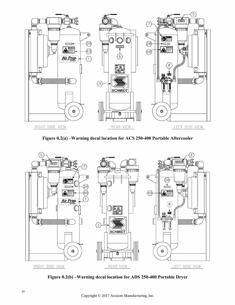
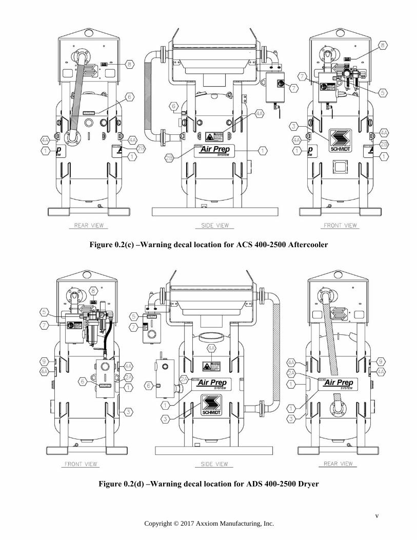
Listed below are the warning labels and the corresponding hazards encountered with this equipment. Refer to Figures 0.1(a) and 0.1(b) for images of the warning decals. Refer to Figures 0.2(a), 0.2(b) and 0.2(c) for the locations of these warning decals.
No. Qty. Part no. Description Hazard
1. 2 7031-019 Air Prep System Not Applicable
2A. 2
7031-033 7031-034 7031-035 7031-036 7031-037 7031-038 7031-051 7031-052
ADS 250 ADS 400 ADS 750 ADS 950
ADS 1200 ADS 1600 ADS 2000 ADS 2500
Not Applicable
2B. 2
7031-025 7031-026 7031-027 7031-028 7031-029 7031-030 7031-049 7031-050
ACS 250 ACS 400 ACS 750 ACS 950
ACS 1200 ACS 1600 ACS 2000 ACS 2500
Not Applicable
3. 1 7031-001 Medium “Schmidt” Not Applicable
4A. 2 7031-007A “Danger”
Pressurized Vessel
Propelled objects will cause serious injury or death. Depressurize vessel prior to performing any maintenance. See Section 6.2.
4B. 2 7031-007B “Danger”
Pressurized Vessel
Propelled objects will cause serious injury or death. Depressurize vessel prior to performing any maintenance. See Section 6.2.
5. 1 7031-017 Inlet Not Applicable
6. 1 7031-018 Outlet Not Applicable
7. 1 7031-057 “Warning”
Read manual before using this machine.
Read and understand operator’s manual before using this machine. Failure to follow operating instructions could result in injury or damage to equipment. See Section 1.0.
8. 1 7031-081 Fill Daily Failure to lubricate air motor will result in motor failure. See Section 5.7.
9. 1 7031-082 “Danger”
Pressurized vessel Handway Components
Propelled objects will cause serious injury or death. Incorrect or damaged handway or manway cover components can result in failure. See Section 6.5.
1) 7031-019 2A) 7031-XXX
Figure 0.1(a) – Warning decal summary (continued)
0.0 Warning Label Identification and Location
iii Copyright © 2017 Axxiom Manufacturing, Inc.
2B) 7031-XXX 3) 7031-001
4A) 7031-007A (4.5” x 8.5”) 4B) 7031-007B (3” x 6”)
5) 7031-017 6) 7031-018
7) 7031-057 8) 7031-081
9) 7031-082 Figure 0.1(b) – Warning decal summary
iv Copyright © 2017 Axxiom Manufacturing, Inc.
Figure 0.2(a) –Warning decal location for ACS 250-400 Portable Aftercooler
Figure 0.2(b) –Warning decal location for ADS 250-400 Portable Dryer
v Copyright © 2017 Axxiom Manufacturing, Inc.
Figure 0.2(c) –Warning decal location for ACS 400-2500 Aftercooler
Figure 0.2(d) –Warning decal location for ADS 400-2500 Dryer

vi Copyright © 2017 Axxiom Manufacturing, Inc.
THIS PAGE IS INTENTIONALLY BLANK
vii Copyright © 2017 Axxiom Manufacturing, Inc.
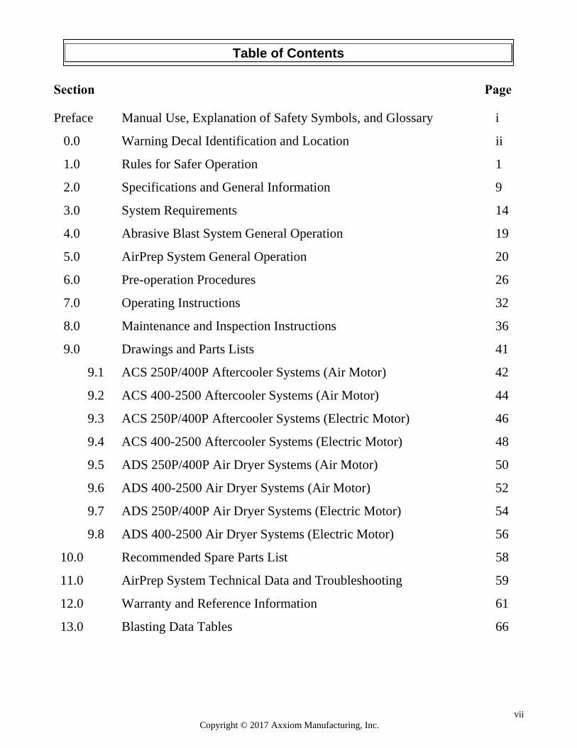
Section Page Preface Manual Use, Explanation of Safety Symbols, and Glossary i
0.0 Warning Decal Identification and Location ii
1.0 Rules for Safer Operation 1
2.0 Specifications and General Information 9
3.0 System Requirements 14
4.0 Abrasive Blast System General Operation 19
5.0 AirPrep System General Operation 20
6.0 Pre-operation Procedures 26
7.0 Operating Instructions 32
8.0 Maintenance and Inspection Instructions 36
9.0 Drawings and Parts Lists 41
9.1 ACS 250P/400P Aftercooler Systems (Air Motor) 42
9.2 ACS 400-2500 Aftercooler Systems (Air Motor) 44
9.3 ACS 250P/400P Aftercooler Systems (Electric Motor) 46
9.4 ACS 400-2500 Aftercooler Systems (Electric Motor) 48
9.5 ADS 250P/400P Air Dryer Systems (Air Motor) 50
9.6 ADS 400-2500 Air Dryer Systems (Air Motor) 52
9.7 ADS 250P/400P Air Dryer Systems (Electric Motor) 54
9.8 ADS 400-2500 Air Dryer Systems (Electric Motor) 56
10.0 Recommended Spare Parts List 58
11.0 AirPrep System Technical Data and Troubleshooting 59
12.0 Warranty and Reference Information 61
13.0 Blasting Data Tables 66
Table of Contents

viii Copyright © 2017 Axxiom Manufacturing, Inc.
THIS PAGE IS INTENTIONALLY BLANK
1 Copyright © 2017 Axxiom Manufacturing, Inc.
1.1. GENERAL RULE FOR SAFER OPERATION.
SCHMIDT® AIRPREP SYSTEMS HAVE BEEN DESIGNED TO BE SAFE WHEN USED IN THE PROPER MANNER. ALL AIRPREP SYSTEMS ARE POTENTIALLY DANGEROUS IF ALL SAFETY PRECAUTIONS ARE NOT RIGOROUSLY FOLLOWED. PROPER TRAINING IS REQUIRED BEFORE OPERATION. PROPER PROCEDURES MUST BE FOLLOWED. THE AIRPREP SYSTEM AND ALL COMPONENTS MUST BE PROPERLY MAINTAINED. FAILURE TO OPERATE, SERVICE AND MAINTAIN THE AIRPREP SYSTEM AS SET FORTH IN THIS MANUAL MAY CAUSE INJURY OR EVEN DEATH TO ANY PERSON USING, SERVICING OR IN THE VICINITY OF THE AIRPREP SYSTEM.
THIS MANUAL IDENTIFIES POTENTIAL HAZARDS BY DANGER, WARNING, AND CAUTION SYMBOLS. HOWEVER, ALL THE RULES, PROCEDURES AND RECOMMENDATIONS MUST BE FOLLOWED. FAILURE TO OPERATE PROPERLY IS VERY LIKELY TO PLACE PERSONS AND PROPERTY AT HIGH RISK OF DAMAGE, INJURY OR EVEN DEATH.
THIS EQUIPMENT IS DESIGNED TO BE USED IN CONJUNCTION WITH ABRASIVE BLAST EQUIPMENT THEREFORE SOME OF THE RULES FOR SAFER OPERATION THAT FOLLOW MAY NOT BE SPECIFIC TO THE USE OF THE AIRPREP SYSTEM HOWEVER, OPERATORS MAY ENCOUNTER THESE POTENTIAL HAZARDS.
AIRPREP SYSTEMS AND THE ABRASIVE BLAST OPERATION ARE POTENTIALLY DANGEROUS IF ALL SAFETY PRECAUTIONS ARE NOT FOLLOWED. FAILURE TO OPERATE THE AIRPREP SYSTEM WITHOUT FOLLOWING ALL THE RULES FOR SAFER OPERATION MAY RESULT IN SERIOUS INJURY OR DEATH TO OPERATING PERSONNEL OR PERSONS IN THE OPERATING VICINITY.
1.2. KNOW YOUR EQUIPMENT. Do Not operate this equipment in a manner other than its intended application (see Section 4.0). Do
Not operate this equipment or any other Schmidt® equipment without following the Rules for Safer Operation and all the operating procedures and instructions. Learn the applications and limitations as well as the specific potential hazards related to this machine. Failure to do so could result in serious injury or death.
1.3. RECEIVE PROPER TRAINING.
Do Not operate this equipment unless you have received operational and maintenance training. Begin by thoroughly reading and understanding this operation and maintenance manual and all included information. Consult an authorized Schmidt distributor or Axxiom manufacturing, Inc.
1.4. PROTECT YOUR FEET.
Do Not operate this equipment without wearing OSHA approved foot protection. Observe all applicable local, state and federal regulations. See Section 3.10 and OSHA 29 CFR 1910.136.
Heavy objects can shift while being blasted and may fall on operators. All operators and personnel in the vicinity must wear OSHA approved foot protection during the operation of this equipment. See Section 3.10 and OSHA 29 CFR 1910.136.
1.0 Rules for Safer Operation
2 Copyright © 2017 Axxiom Manufacturing, Inc.
1.5. PROTECT YOUR EYES. Do Not operate this equipment without wearing OSHA approved safety glasses. Observe all applicable local, state and federal safety regulations. See Section 3.10 and OSHA 29 CFR 1910.133.
The abrasive blast operation produces a dusty work environment which can leave dust that can be blown in the face and eyes of operators. All operators and personnel in the vicinity must wear OSHA approved safety glasses during the operation of this equipment. See Section 3.10 and OSHA 29 CFR 1910.133.
1.6. PROTECT YOUR LUNGS.
Do Not operate this equipment without wearing OSHA approved respiratory protection. Abrasive blasting produces dust contaminated with toxic substances from the abrasive used, the coating being removed, and the object being blasted. This dust may contain silica which can cause severe and permanent lung damage, cancer, and other serious diseases. Do Not breathe the dust. Do Not rely on your sight or smell to determine if dust is in the air. Silica and other toxic substances may be in the air without a visible dust cloud. If air-monitoring equipment for silica is not provided at the worksite, then all personnel MUST wear appropriate respiratory protection when using or servicing this equipment. Breathing air supplied to respirators must be of acceptable quality. Consult your employer and OSHA regarding the appropriate respiratory protection and breathing air quality. See Sections 3.9, 3.10, and OSHA 29 CFR 1910.134.
Abrasive blasting produces dust which may contain silica and other toxic substances that can cause severe and permanent lung damage, cancer, and other serious diseases if inhaled. All operators and personnel in the vicinity must wear OSHA approved respiratory protection during the operation of this equipment. See Sections 3.9, 3.10, and OSHA 29 CFR 1910.134.
1.7. BREATHING AIR QUALITY. Do Not use breathing air that does not meet OSHA Class D standards. Use extreme caution when selecting a source of breathing air. Breathing air provided by an oil-lubricated air compressor can contain carbon monoxide; therefore, use of a carbon monoxide detector is required (See Section 3.10). Carbon monoxide can be in the compressed air produced by an oil-lubricated air compressor when it is operated at extremely high temperature; therefore a high temperature alarm is required to alert the operators when this condition exists. See Section 3.9 and reference OSHA 29 CFR 1910.134(i).
Extreme caution must be taken when connecting to industrial air sources. Industrial locations can have sources of compressed gases such as nitrogen which is fatal if used as a breathing air source. Verify that the air source is breathable air.
Breathing air must meet OSHA Class D standards. Use of breathing air sources that do not meet Class D standards can cause asphyxiation and result in death. Verify that all air sources are breathable quality and use a high-temperature alarm and a carbon monoxide monitor when required. See Sections 3.9, 3.10 and OSHA 29 CFR 1910.134(i). Enclosed blast areas must be ventilated to reduce airborne dust to an acceptable level as required by OSHA 29 CFR 1910.1000.
3 Copyright © 2017 Axxiom Manufacturing, Inc.
1.8. PROTECT YOUR HEARING. Do Not operate this equipment without wearing OSHA approved hearing protection. Observe all applicable local, state and federal safety regulations. See Section 3.10 and refer to OSHA 29 CFR 1910.95.
Loud noise is generated by the blast nozzle and the blowdown operation of this equipment. All operators and personnel in the vicinity must wear OSHA approved hearing protection during the operation of this equipment. See Section 3.10 and refer to OSHA 29 CFR 1910.95.
1.9. PROTECT YOUR PERSON Abrasive blasting produces dust contaminated with toxic substances from the abrasive used, the
coating being removed, and the object being blasted. All blast operators and other personnel involved in the blast operation or in the vicinity of the blast operation should wear protective clothing. The protective clothing should be disposable or washable work clothes that should be removed at the worksite so that contaminated dust is not transferred into automobiles or homes. See Section 3.10 and refer to OSHA 29 CFR 1910.94 and 1910.134.
1.10. ADHERE TO ALL REGULATIONS.
Do Not operate this equipment without observing all local, state, and federal safety regulations including, but not limited to, OSHA (Occupational Safety and Health Administration).
1.11. STAY ALERT.
Do Not operate this equipment when you are tired or fatigued. Use caution and common sense while operating and/or performing maintenance on this equipment.
1.12. DO NOT USE DRUGS, ALCOHOL, or MEDICATION.
Do Not operate this equipment while under the influence of drugs, alcohol, or any medication.
1.13. PROTECT BYSTANDERS. Do Not allow blast equipment operators and other personnel to enter the vicinity of the blast operation without providing respiratory protective equipment that meets OSHA regulations. If dust concentration levels exceed the limitations set in OSHA 29 CFR 1910.1000 then respirators are required.
1.14. KEEP CHILDREN AND VISITORS AWAY. Do Not allow children or other non-operating personnel to contact this equipment or the connecting hoses and cords. Keep children and non-operating personnel away from work area.
1.15. AVOID DANGEROUS ENVIRONMENTS. Do Not operate this equipment without familiarizing yourself with the surrounding environment. The blast operation creates high level of noise which may prevent the operator from hearing other possible dangers (i.e. traffic or moving equipment). In such situations a stand-by watch person may be necessary to protect against injury to personnel.
1.16. AVOID DANGEROUS ENVIRONMENTS.
Do Not use this equipment in areas cluttered with debris. Debris in the work area can create tripping hazards which can cause the operator to lose control of the blast hose and result in injury to operating personnel. Keep work area clean and well lit. When working at an elevated location, pay attention to articles and persons below.
4 Copyright © 2017 Axxiom Manufacturing, Inc.
1.17. AVOID DANGEROUS ENVIRONMENTS. Do Not operate this equipment in elevated areas without using fall protection equipment. Certain applications of this equipment may require the use of scaffolding. Use of scaffolding creates hazardous situations such as tripping and fall hazards which can result in serious injury or death to operating personnel. Consult OSHA 29 CFR 1910 Subpart D.
1.18. AVOID DANGEROUS ENVIRONMENTS. Do Not blast objects that are not properly secured. The blast operation can cause the blasted object to shift or move. Extremely large objects to be blasted can create a crush hazard to operating personnel which can result in serious injury or death. Properly secure the object to be blasted.
1.19. AVOID DANGEROUS ENVIRONMENTS. Do Not blast objects used to store flammable materials. The blast operation can cause sparks which can ignite fumes or residual flammable materials inside enclosed containers which can explode resulting in serious injury or death to operating personnel.
1.20. ELECTRICALLY GROUND EQUIPMENT. Static electricity is generated by the abrasive flow through the blast hose. To protect against static electrical shock to operating personnel only use static dissipating blast hose and install a grounding strap on the abrasive blaster.
1.21. MAINTAIN VESSEL INTEGRITY. Do Not operate this equipment with the pressure vessel damaged, or with any part of it worn or
damaged. Do Not operate this equipment in a condition that may cause failure of the pressure vessel. See Rules 1.22 through 1.32 below.
An AirPrep System is a Pressurized Vessel. Alterations, damage, or misuse of the pressure vessel can result in rupturing. Damaged or incorrect components used on the AirPrep System can result in rupturing. The compressed air inside a pressurized vessel contains a dangerously high level of energy which can propel objects and cause serious injury or death.
1.22. NEVER OPERATE OVER MAXIMUM WORKING PRESSURE. Do Not operate this equipment above maximum allowable working pressure (MAWP) at maximum
operating temperature (°F) shown on the ASME nameplate attached to the vessel. See Sections 2.2 and 8.1.
1.23. INSTALL PRESSURE RELIEF DEVICE.
Do Not operate this equipment without a pressure relief device in place. The ASME Code requires that all vessels be equipped with pressure relief devices prior to installation. The pressure relief device must be set at the maximum allowable working pressure of the pressure vessel. See the ASME nameplate attached to the vessel typically located above the handway. See Section 3.11 for information regarding the pressure relief valve.
1.24. NEVER OPERATE BEYOND ALLOWABLE TEMPERATURE RANGE. Do Not operate this equipment above the maximum allowable temperature at the allowable pressure or below the minimum design metal temperature (MDMT) shown on the pressure vessel nameplate. The characteristics of the pressure vessel metal are weakened when the temperature is outside the operating range. Operating the pressure vessel outside of allowable temperature range can result in rupturing and cause serious injury or death. See Section 2.2.
5 Copyright © 2017 Axxiom Manufacturing, Inc.
1.25. ASME NAMEPLATE REQUIRED. Do Not operate this equipment if the ASME pressure vessel nameplate is missing. Contact Axxiom Manufacturing, Inc. for technical support.
1.26. DO NOT MODIFY VESSEL.
Do Not modify or alter this equipment, or any blast equipment, or controls thereof without written consent from Axxiom Manufacturing, Inc. Do Not weld, grind, or sand the pressure vessel. It will not be safe to operate. Non-authorized modifications could lead to serious injury or death. Non-authorized modifications will void the warranty and the ASME/NB integrity.
1.27. DO NOT HAMMER ON VESSEL. Do Not hammer on or strike any part of the pressure vessel. Hammering on the pressure vessel can create cracks and cause rupturing.
1.28. FIRE DAMAGE NOTICE. Do Not operate if the pressure vessel has been damaged by fire. If damaged, take out of service immediately and have it inspected and/or repaired by a qualified facility. Contact Axxiom Manufacturing, Inc. for technical support.
1.29. INSPECT VESSEL REGULARLY. Do Not operate this equipment with damage to the pressure vessel. It is not safe. Inspect outside and inside of the pressure vessel regularly for corrosion or damage (i.e. dents, gouges or bulges). If damaged, take out of service immediately and have it inspected and/or repaired by a qualified facility. Contact Axxiom Manufacturing, Inc. for technical support. See Section 8.0.x
1.30. CHECK FOR LEAKS IN VESSEL. Do Not operate this equipment if there is a leak in the pressure vessel. If leaking, take out of service immediately and have it inspected and/or repaired by a qualified facility. Contact Axxiom Manufacturing, Inc. for technical support. See Section 8.0.
1.31. INSPECT HANDWAY ASSEMBLY. Do Not operate the abrasive blaster without first inspecting the handway assembly. To insure proper operation all handway components must be the correct size for the vessel handway opening. See Section 6.3.
1.32. NEVER MODIFY BLOWDOWN. Do Not connect the blowdown on this equipment onto a common header with any other unit of any
description, or any other source of compressed air, without first making sure a check valve is used between the header and this unit. Do Not install this equipment sharing piping with another unit of higher discharge pressure and capacity. A safety hazard could occur in the form of a back-flow condition. Do Not install a muffler or silencer on the blowdown that is not designed for use on AirPrep system. It can cause a malfunction and can result in a hazardous condition.
6 Copyright © 2017 Axxiom Manufacturing, Inc.
1.33. DEPRESSURIZE VESSEL BEFORE PERFORMING MAINTENANCE. Do Not remove, repair, or replace any item on this equipment while it is pressurized. Do Not
attempt to perform maintenance or load abrasive while this equipment is pressurized or is even capable of being pressurized. This means the inlet ball valve should be closed and the air supply should be shut off or disconnected. Anytime the manual blowdown valve is closed it should be assumed that the abrasive blast vessel is pressurized.
An AirPrep System is a Pressurized Vessel. The compressed air inside a pressurized vessel contains a dangerously high level of energy which can propel objects and cause serious injury or death. Depressurize vessel before performing any maintenance. See Section 6.2.
1.34. ALWAYS USE REMOTE CONTROLS. Do Not sell, rent, or operate abrasive blasters without remote controls. OSHA regulations require
remote controls on all abrasive blasters. All abrasive blasters must be equipped with automatic (deadman) type remote controls (either pneumatic or electric). Failure to use remote controls can cause serious injury or death to the operator(s) or other personnel in the blasting area. Reference OSHA 29 CFR 1910.244(b).
1.35. NEVER USE BLEEDER TYPE DEADMAN VALVES. Do Not use bleeder type deadman valves on any Schmidt® abrasive blaster. The use of A-BEC, Clemco, or a similar bleeder type deadman valve can, without warning, cause unintentional start-up which can result in serious personal injury. A particle of dirt from the air hose can plug the bleed hole in the deadman valve and cause the blast outlet to turn on.
1.36. CHECK FOR DAMAGED PARTS. Do Not use this equipment with damaged components. Periodically check all valves, hoses, fittings,
pipe and pipe fittings (internal and external) to see that they are in good condition. Repair or replace any component that shows any sign of wear, leakage, or any other damage. See Section 8.0.
Damaged components can fail during operation and result in serious injury or death to operating
personnel.
1.37. ALWAYS USE SAFETY PINS ON HOSE COUPLING CONNECTIONS. Do Not use this equipment without hose coupling safety pins in place and hose whip checks
installed on all air and blast hoses. All blast hose couplings and air hose couplings have pin holes that must be safety pinned to protect against accidental disconnections. Accidental hose disconnection can cause serious injury or death. See Sections 5.14 and 8.8.
1.38. ALWAYS USE CORRECT REPLACEMENT PARTS AND ACCESSORIES. Do Not use replacement parts or accessories that are not rated for pressures equal to or higher than your equipment’s operating pressure. Improper hoses and/or fittings used on, or connected to the Schmidt equipment can rupture and cause serious injury or death.
Do Not use replacement parts that are not Schmidt® original factory replacement parts. Non-original parts may not fit properly and can cause equipment damage and/or failure which can result in serious injury to operating personnel. Consult Axxiom Manufacturing, Inc.
Use of replacement components that are not Schmidt® original factory replacement parts may result in equipment failure which can result in serious injury to operating personnel.
7 Copyright © 2017 Axxiom Manufacturing, Inc.
1.39. ALWAYS USE CORRECT PRESSURE RATED ACCESSORIES. Do Not use air reservoirs or moisture separator tanks that are not rated for use in compressed air applications. Air reservoirs and moisture separator tanks larger than 6 inches inside diameter must have an ASME code stamp.
An air reservoir or moisture separator tank is a Pressurized Vessel. The compressed air inside a pressurized vessel contains a dangerously high level of energy which can explode propelling objects and result in serious injury or death to operating personnel. Air reservoir and moisture separator tanks must be ASME coded tanks.
1.40. NEVER AIM BLAST NOZZLE TOWARDS ANY PERSON. Do Not aim the blast nozzle towards yourself or any person. A system malfunction or a blocked blast nozzle that clears can trigger accidental start up resulting in injury to personnel.
1.41. NEVER USE ABRASIVE NOT INTENDED FOR BLAST EQUIPMENT. Do Not use abrasive blast media containing free silica. Silica can cause silicosis or other related
respiratory damage. Verify that the abrasive is intended for use in blasting equipment. Personal protective equipment, including airline filters and respirators, must be used for all abrasive blasting operations. Observe all applicable local, state and federal safety regulations. See Sections 3.8, 3.10, and reference OSHA 29 CFR 1910.134.
1.42. CHECK ABRASIVE FOR DEBRIS. Do Not use blast abrasive that contains trash or other debris. Trash or debris can create a blockage and cause equipment malfunction. Screen recycled abrasive to remove trash.
1.43. STOP OPERATION IMMEDIATELY IF ANY ABNORMALITY IS DETECTED. Do Not operate this equipment if anything abnormal is seen during operation. Stop operation immediately for inspection. Refer to Section 8.0 for maintenance and inspection details.
1.44. DO NOT OVERLOAD THE LIFT EYES. Do Not load the lifting eyes above the rated capacity. Do Not lift the blast vessel by any point other than the lifting eyes or designated lift points. Do Not lift the blast vessel while it is pressurized. See Section 2.6.
1.45. AVOID WET ENVIRONMENTS. Do Not expose this equipment to rain. Do not use this equipment in wet conditions. AirPrep Systems operated outdoors must be protected from weather.
1.46. AVOID CORROSIVE ENVIRONMENTS.
Do Not locate this equipment in corrosive atmospheres as rapid deterioration of fan shroud, cooling coil, fan and motor may take place resulting in reduced life.
1.47. AVOID EXTREME TEMPERATURES. Do Not expose AirPrep Systems fan motors to extreme temperatures. The motors furnished are built for fan duty only. Consideration should be given to the installation location so motors are not subjected to extreme temperatures. AirPrep Systems with air motor have a maximum operating temperature of 250°F (121°C). Refer to the motor nameplate for AirPrep Systems with electric motors. Do Not operate AirPrep Systems below 35°F (1°C).
8 Copyright © 2017 Axxiom Manufacturing, Inc.
1.48. DO NOT CYCLE AIRPREP SYSTEM FAN. AirPrep Systems fan and drive motors are designed for continuous operation. Do Not alter to a cycled fan mode.
1.49. ALLOW PROPER CLEARANCE. Do Not install this equipment where airflow to aftercooler fan will be restricted. For proper air flow, a minimum of 12" should be allowed between the aftercooler fan and any walls or obstructions.
1.50. DO NOT OPERATE WITH GUARDS REMOVED.
Do Not operated AirPrep Systems with the fan guard removed. Do Not place hands near radiator fan guard. Contact with rotating fan can result in serious injury to operating personnel.
1.51. ELECTRIC FAN MOTORS MUST BE INSTALLED BY QUALIFIED PERSONNEL. Do Not connect electric motors to a power supply that does not have the same characteristics as shown on the motor nameplate. Be sure to provide proper fusing to minimize chance of possible motor burnout. Before starting the motor, follow manufacturer’s recommendations. Turn the fan by hand to eliminate possible motor burnout in the event the fan has been damaged in shipment. Observe operation after the motor has been started for the first time.
1.52. MAINTAIN WARNING DECALS. Do Not remove, cover, obstruct, or paint over any warnings, cautions, or instructional material attached. Warning decals must be installed, maintained, and located to be visible and with enough light for legibility. See Sections 0.0 and 8.10.
1.53. SAVE THIS OPERATION AND MAINTENANCE MANUAL.
Refer to this operation and maintenance manual as needed as well as any additional information included from other manufacturers. Never permit anyone to operate this equipment without having him/her first read this manual and receive proper training. Make this manual readily available to all operating and maintenance personnel. If the manual becomes lost or illegible replace it immediately. This operation and maintenance manual should be read periodically to maintain the highest skill level; it may minimize chance of a serious accident.
1.54. SAFETY REFERENCES See Section 12.4 for safety information sources and contact information. Use these sources to obtain additional information regarding all aspects of blast operation safety.
9 Copyright © 2017 Axxiom Manufacturing, Inc.
2.1 Notes To Distributors and Owners
2.1.1. Verify that the operation and maintenance manual is included with the AirPrep System when it is received. Verify that the operation and maintenance manual is included with the AirPrep System when it is delivered to the purchaser.
2.1.2. This equipment is intended for knowledgeable and experienced users. No person or persons
should be allowed to operate this equipment without first receiving proper training in abrasive blasting operation and use of this equipment.
2.1.3. Immediately notify Axxiom Manufacturing, Inc. of any instances of use of this equipment
in any manner other than the intended application. See Section 4.0. 2.1.4. Only qualified personnel should load and unload this equipment for shipping. Slings or
other lifting devices must only be attached to the designated lifting points. See the lifting diagrams shown in Section 2.6.
2.1.5. For further information contact: Axxiom Manufacturing, Inc. 11927 South Highway 6
Fresno, Texas 77545
Phone: 1-800-231-2085 Fax: 1-281-431-1717 Website: www.SchmidtAbrasiveBlasting.com
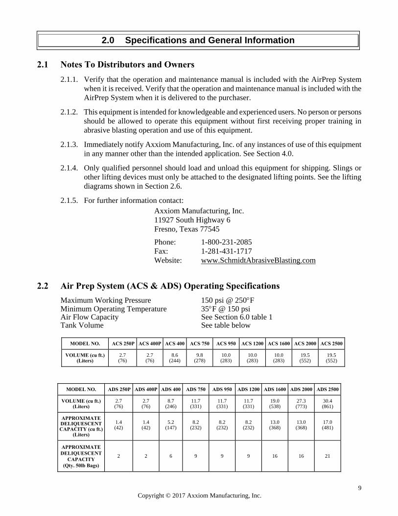
2.2 Air Prep System (ACS & ADS) Operating Specifications
Maximum Working Pressure 150 psi @ 250F Minimum Operating Temperature 35F @ 150 psi Air Flow Capacity See Section 6.0 table 1 Tank Volume See table below
MODEL NO. ACS 250P
ACS 400P
ACS 400
ACS 750
ACS 950
ACS 1200
ACS 1600
ACS 2000
ACS 2500
VOLUME (cu ft.)
(Liters)
2.7 (76)
2.7 (76)
8.6
(244)
9.8
(278)
10.0 (283)
10.0 (283)
10.0 (283)
19.5 (552)
19.5 (552)
MODEL NO.
ADS 250P
ADS 400P
ADS 400
ADS 750
ADS 950
ADS 1200
ADS 1600
ADS 2000
ADS 2500
VOLUME (cu ft.)
(Liters)
2.7 (76)
2.7 (76)
8.7
(246)
11.7 (331)
11.7 (331)
11.7 (331)
19.0 (538)
27.3 (773)
30.4 (861)
APPROXIMATE DELIQUESCENT CAPACITY (cu ft.)
(Liters)
1.4 (42)
1.4 (42)
5.2 (147)
8.2 (232)
8.2 (232)
8.2 (232)
13.0 (368)
13.0 (368)
17.0 (481)
APPROXIMATE DELIQUESCENT
CAPACITY (Qty. 50lb Bags)
2 2 6 9 9 9 16 16 21
2.0 Specifications and General Information
10 Copyright © 2017 Axxiom Manufacturing, Inc.
2.3 Important Reference Numbers
Fill in the AirPrep Systems model number and serial number in the blank spaces below. These will be used for reference whenever service or maintenance is required. AirPrep System Model Number AirPrep System Part Number AirPrep System Serial Number National Board Number
2.4 Vessel Information
2.4.1. All pressure vessels used in Schmidt AirPrep Systems are manufactured in strict accordance with the provisions of the ASME Code Section VIII, Div. 1.
2.4.2. In order to maintain the high level of quality and quality control used in the manufacture of
this vessel, it is required that any and all welded repairs to this vessel be performed by a reputable shop holding a National Board “R” Stamp and/or an ASME “U” stamp, depending on state or city law. Welding on the vessel performed by welders not properly qualified per the ASME Code voids the ASME/NB integrity of that particular vessel.
2.5 Notes
11 Copyright © 2017 Axxiom Manufacturing, Inc.
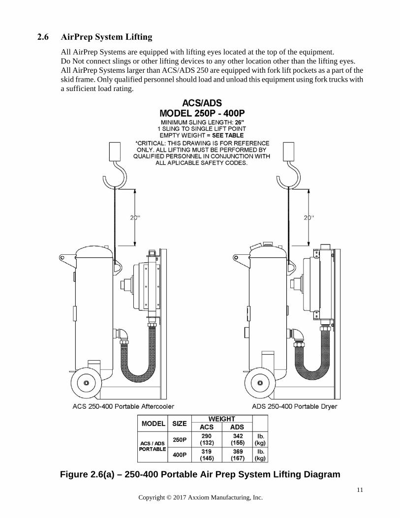
2.6 AirPrep System Lifting
All AirPrep Systems are equipped with lifting eyes located at the top of the equipment. Do Not connect slings or other lifting devices to any other location other than the lifting eyes. All AirPrep Systems larger than ACS/ADS 250 are equipped with fork lift pockets as a part of the skid frame. Only qualified personnel should load and unload this equipment using fork trucks with a sufficient load rating.
Figure 2.6(a) – 250-400 Portable Air Prep System Lifting Diagram
12 Copyright © 2017 Axxiom Manufacturing, Inc.
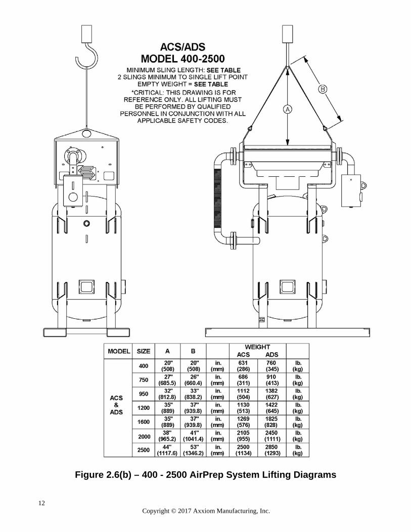
Figure 2.6(b) – 400 - 2500 AirPrep System Lifting Diagrams
13 Copyright © 2017 Axxiom Manufacturing, Inc.
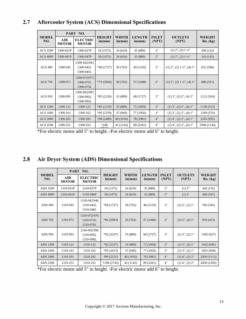
2.7 Aftercooler System (ACS) Dimensional Specifications
MODEL
NO.
PART NO.
HEIGHT in(mm)
WIDTH in(mm)
LENGTH in(mm)
INLET (NPT)
OUTLETS (NPT)
WEIGHT lbs. (kg)
AIR
MOTOR
ELECTRIC
MOTOR ACS 250P
1300-021P
1300-027P
54 (1372)
24 (610)
35 (889)
2" (1) 2", (2) 1 ½"
290 (132)
ACS 400P
1300-041P
1300-047P
58 (1473)
24 (610)
35 (889)
2" (1) 2", (2) 1 ½"
319 (145)
ACS 400
1300-041
1300-042/043
1300-042L
1300-043L
*68 (1727)
30 (762)
49 (1245)
2" (1) 2", (2) 1 ½", (4) 1"
631 (286)
ACS 750
1300-071
1300-072/073
1300-072L
1300-073L
*73 (1854)
30 (762)
57 (1448)
2" (1) 2", (2) 1 ½", (4) 1"
686 (311)
ACS 950
1300-091
1300-092/093
1300-092L
1300-093L
*85 (2159)
35 (889)
68 (1727)
3" (1) 3", (2) 2", (4) 1"
1112 (504)
ACS 1200
1300-121
1300-122
*85 (2159)
35 (889)
72 (1829)
3"
(1) 3", (2) 2", (4) 1"
1130 (513)
ACS 1600
1300-161
1300-162
*85 (2159)
37 (940)
77 (1956)
3"
(1) 3", (2) 2", (4) 1"
1269 (576)
ACS 2000
1300-201
1300-202
†98 (2489)
40 (1016)
78 (1981)
4"
(1) 4", (2) 2", (4) 1"
2105 (955)
ACS 2500
1300-251
1300-252
†108
(2743)
45 (1143)
89 (2261)
4"
(1) 4", (2) 2", (4) 1"
2500 (1134)
*For electric motor add 5" to height. †For electric motor add 6" to height.
2.8 Air Dryer System (ADS) Dimensional Specifications
MODEL
NO.
PART NO.
HEIGHT in(mm)
WIDTH in(mm)
LENGTH in(mm)
INLET (NPT)
OUTLETS (NPT)
WEIGHT lbs. (kg)
AIR
MOTOR
ELECTRIC
MOTOR
ADS 250P
1310-021P
1310-027P
54 (1372)
24 (610)
35 (889)
2"
(1) 2”
342 (155)
ADS 400P
1310-041P
1310-046P
58 (1473)
24 (610)
35 (889)
2"
(1) 2"
369 (167)
ADS 400
1310-041
1310-042/046
1310-042L
1310-046L
*68 (1727)
30 (762)
48 (1219)
2" (1) 2", (2) 1"
760 (345)
ADS 750
1310-071
1310-072/076
1310-072L
1310-076L
*82 (2083)
30 (762)
57 (1448)
2" (1) 2", (2) 1"
910 (413)
ADS 950
1310-091
1310-092/096
1310-092L
1310-096L
*92 (2337)
35 (889)
68 (1727)
3" (1) 3", (2) 1"
1382 (627)
ADS 1200
1310-121
1310-122
*92 (2337)
35 (889)
72 (1829)
3"
(1) 3", (2) 1"
1422 (645)
ADS 1600
1310-161
1310-162
*95 (2413)
37 (940)
77 (1956)
3"
(1) 3", (2) 1"
1825 (828)
ADS 2000
1310-201
1310-202
†99 (2515)
40 (1016)
78 (1981)
4"
(1) 4", (2) 2"
2450 (1111)
ADS 2500
1310-251
1310-252
†108 (2743)
45 (1143)
89 (2261)
4"
(1) 4", (2) 2"
2850 (1293)
*For electric motor add 5" to height. †For electric motor add 6" to height.
14 Copyright © 2017 Axxiom Manufacturing, Inc.
3.2 Compressed Air Requirements
Blast nozzle The blast nozzle size and blast pressure determine the compressed air requirements. Available air flow capacity and/or air compressor size must be considered before selecting the blast nozzle size. An air source dedicated to the abrasive blast system is preferred to reduce system pressure drops and back flow of air. If an existing air compressor will be used or a limited air supply is available, then the blast nozzle must be selected based on these conditions. Be aware that as the blast nozzle wears the air demand will increase. See Table 1 in Section 13.0 for air consumption by nozzle size at various pressures. The required air consumption will be used to select the proper size AirPrep System.
3.3 Air compressor size Air compressor size is crucial to the operation of the abrasive blasting equipment which in turn will affect the selection of the AirPrep system. Blast nozzle selection and desired productivity must be evaluated to determine the air flow requirements prior to selecting the air compressor size. Sufficient air supply capacity is necessary to maintain the system air pressure. Insufficient air flow capacity will result in reduced blast nozzle pressure and lost productivity. The air compressor must be large enough to supply:
i. The sum of blast air requirements for each nozzle at the highest pressure that will be
used (see Section 13.0, Table 1).
ii. The 12 CFM breathing air supplied to each blast operator respirator. NOTE: Reference OSHA regulations regarding requirements for breathing air, especially when an oil-lubricated air compressor is used.
iii. The AirPrep System size should be selected based on the size and capability of the air
compressor to be used to meet the air requirements determined above.
3.4 AirPrep System Air Supply Lines The air supply hose and fittings connected to the inlet and outlets of the AirPrep System must be rated at a minimum of 150 psi operating pressure. The air supply hose from the air compressor to the AirPrep System should be at least the same diameter as the air inlet piping (see Section 2.7). AirPrep Systems are equipped with smaller secondary outlet ports which can be reduced in size by installing pipe bushings to match the connecting equipment. Again the air requirement of the connecting equipment must be considered so that the proper size piping/hose is selected. See Section 5.14.
3.5 AirPrep System Air Pressure The standard maximum operating pressure for AirPrep Systems is 150 psig; however custom systems may have varying operating pressure. The maximum operating pressure for the AirPrep System is stamped on the ASME nameplate attached to the vessel. AirPrep Systems equipped with air motors to drive the cooling fan are supplied with an air pressure regulator. This air regulator is to reduce the air pressure to the required operating pressure of the fan air motor. The regulator is pre-set at the manufacturer and should not be altered. The required operating pressure for the fan air motor is given in Section 11.0, Table 2.
3.0 System Requirements
15 Copyright © 2017 Axxiom Manufacturing, Inc.
3.6 Blast System Air Quality AirPrep Systems are equipped with an inlet filter/separator to remove debris and condensed moisture from the incoming air flow; however, if the air source contains an excessive amount of debris, it may be necessary to install a preliminary filter upstream of the AirPrep System inlet. Excessive contamination of the incoming air can clog the heat exchanger of the AirPrep System and cause expensive damage to the system.
3.7 Electrical Requirements
AirPrep Systems can be equipped with electric fan motors. On units equipped with electric fan motors the supply voltage can range from 110Vac (single phase) to 460Vac (three phase). Each electric motor can be wired one of two voltages as specified by the purchaser at the time of purchase however, the motor can be rewired at installation. If the unit is to be rewired it may be necessary to change the motor starter and/or the thermal overload strips. Only a qualified electrician should install and/or make electrical changes to the AirPrep Systems.
Power connections to AirPrep System with electric motors expose operators to high electrical voltages. Contact with high electrical voltages can result in serious injury or death. Only qualified personnel should install or perform maintenance on the electrical system.
3.9 Breathing Air Quality All blast operators must be supplied with and required to use NIOSH approved air-fed respirators. Breathing air supplied to these respirators must meet Grade D air quality standards as specified by OSHA 29 CFR 1910.134(i) and the Compressed Gas Association Specifications ANSI/CGA G-7.1. Consult these specifications when selecting a source of breathing air. Breathing air must be clean, dry, contaminant-free, and provided at a pressure and volume specified by NIOSH. Use NIOSH approved air filters on all sources of breathing air. See Section 3.10.
Breathing air filters do not remove carbon monoxide or any other toxic gases. Use a carbon monoxide monitor to detect unacceptable levels. Consult OSHA 29 CFR 1910.134(i).
Many sources of breathing air are available such as air cylinders, free-air pumps, oil-less air compressors, and oil lubricated air compressors. The most commonly used is the same air compressor that is used for the blast air which most often is oil lubricated. Breathing air provided by an oil-lubricated air compressor can contain carbon monoxide and therefore requires the use of a carbon monoxide detector (See Section 3.10). Carbon monoxide can be in the compressed air produced by an oil-lubricated air compressor when it is operated at extremely high temperature; therefore, a high temperature alarm is required to alert the operators when this condition exists.
Oil lubricated air compressors can produce carbon monoxide. Carbon monoxide can cause asphyxiation and result in death. Use a high-temperature alarm and a carbon monoxide monitor when an oil lubricated air compressor is used to supply breathing air. Consult OSHA 29 CFR 1910.134(i).
16 Copyright © 2017 Axxiom Manufacturing, Inc.
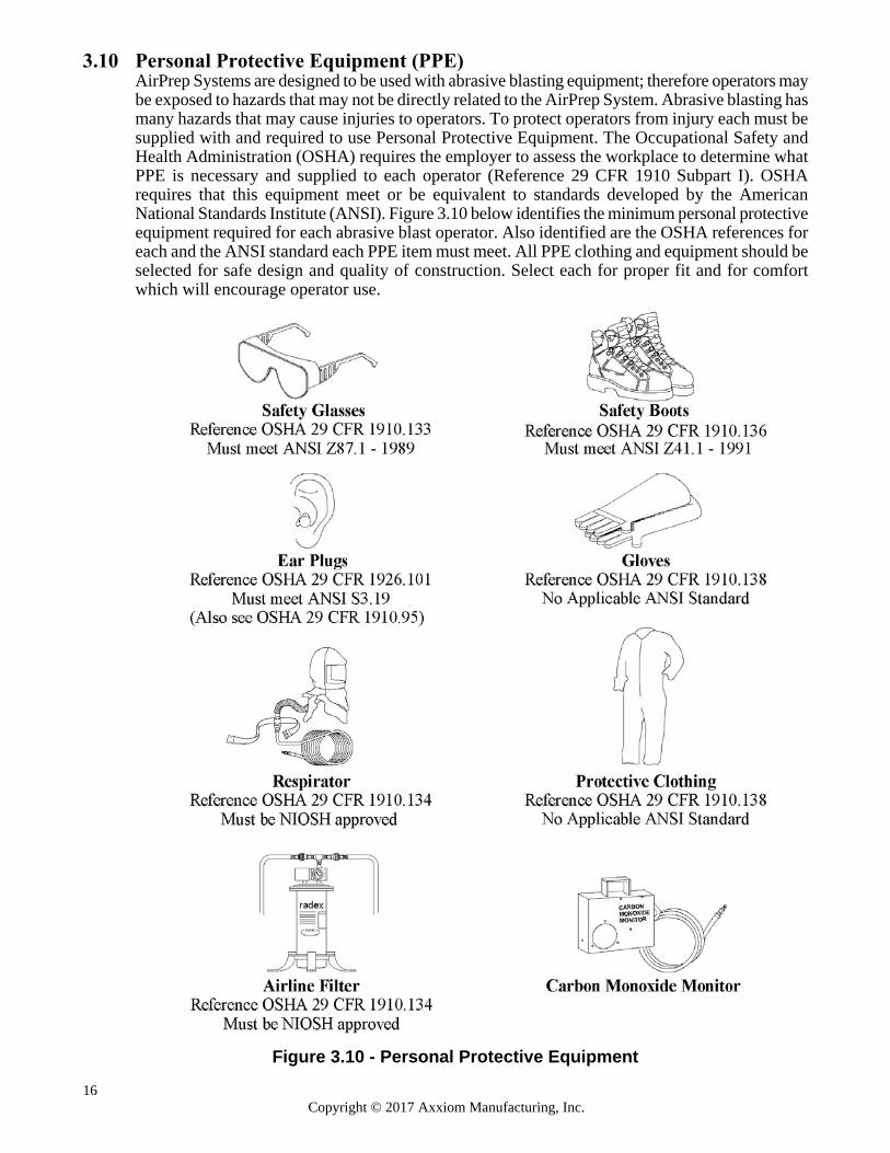
3.10 Personal Protective Equipment (PPE) AirPrep Systems are designed to be used with abrasive blasting equipment; therefore operators may be exposed to hazards that may not be directly related to the AirPrep System. Abrasive blasting has many hazards that may cause injuries to operators. To protect operators from injury each must be supplied with and required to use Personal Protective Equipment. The Occupational Safety and Health Administration (OSHA) requires the employer to assess the workplace to determine what PPE is necessary and supplied to each operator (Reference 29 CFR 1910 Subpart I). OSHA requires that this equipment meet or be equivalent to standards developed by the American National Standards Institute (ANSI). Figure 3.10 below identifies the minimum personal protective equipment required for each abrasive blast operator. Also identified are the OSHA references for each and the ANSI standard each PPE item must meet. All PPE clothing and equipment should be selected for safe design and quality of construction. Select each for proper fit and for comfort which will encourage operator use.
Figure 3.10 - Personal Protective Equipment
17 Copyright © 2017 Axxiom Manufacturing, Inc.
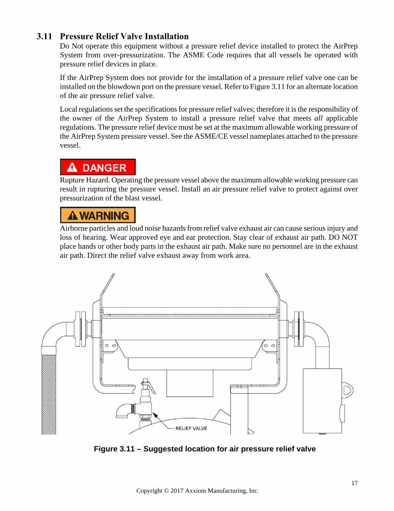
3.11 Pressure Relief Valve Installation Do Not operate this equipment without a pressure relief device installed to protect the AirPrep System from over-pressurization. The ASME Code requires that all vessels be operated with pressure relief devices in place. If the AirPrep System does not provide for the installation of a pressure relief valve one can be installed on the blowdown port on the pressure vessel. Refer to Figure 3.11 for an alternate location of the air pressure relief valve.
Local regulations set the specifications for pressure relief valves; therefore it is the responsibility of the owner of the AirPrep System to install a pressure relief valve that meets all applicable regulations. The pressure relief device must be set at the maximum allowable working pressure of the AirPrep System pressure vessel. See the ASME/CE vessel nameplates attached to the pressure vessel.
Rupture Hazard. Operating the pressure vessel above the maximum allowable working pressure can result in rupturing the pressure vessel. Install an air pressure relief valve to protect against over pressurization of the blast vessel.
Airborne particles and loud noise hazards from relief valve exhaust air can cause serious injury and loss of hearing. Wear approved eye and ear protection. Stay clear of exhaust air path. DO NOT place hands or other body parts in the exhaust air path. Make sure no personnel are in the exhaust air path. Direct the relief valve exhaust away from work area.
Figure 3.11 – Suggested location for air pressure relief valve
18 Copyright © 2017 Axxiom Manufacturing, Inc.
3.12 INSTALLATION CHECKLIST (Photocopy this page to use as a worksheet)
□ Accessories: confirm receipt as purchased with the AirPrep System.
□ Inspect AirPrep System: check for possible damage during shipment. See Section 8.0 for inspection instructions.
□ Clean AirPrep ADS System: remove handway cover and check for debris inside. If Replace handway cover per instructions in Section 6.3.
□ CFM available: determine available air supply (cfm) and record here. Confirm AirPrep System capacity meets or exceeds the available cfm from above. See Sections 3.2, 3.3, and 3.5 for information on determining air requirements.
□ Air inlet/outlet connection: install air supply piping or connect an air supply hose that is the same size as the air inlet size. See Section 3.4 for details.
□ Deliquescent (AirPrep ADS Systems): fill dryer vessel with deliquescent tablets. See Section 2.2 for capacity.
□ Breathing air: provide Grade D air source for blast operators. See Section 3.9.
□ PPE: provide all the necessary personal protective equipment. See Section 3.10.
□ Pressure relief valve: install relief valve if not provided on AirPrep System. See Section 3.11 for information on pressure relief valve installation.
□ AirPrep System radiator drain: for environments where freezing is possible install a radiator drain ball valve to drain water that accumulates in the radiator. Critical: This will protect the radiator from damage caused by inside water freezing. See Section 5.3.
□ Air motor lubricator: fill lubricator with SAE #10 oil and set correct drip rate as detailed in Section 7.2. Also see Sections 5.4, 5.6, & 8.5.4.
□ Air motor pressure regulator: correct pressure is set by the manufacturer; however, to insure optimum operation confirm that it is set correctly. See Sections 5.5 and 11.2.
□ Electric power: AirPrep Systems equipped with an electric motor that must be installed by a qualified technician. Confirm the specified voltage to insure proper installation. Note: motor starter thermal units are installed for the voltage specified at the time of purchase; if the voltage is changed during installation risk of overload or under protection will result. See Sections 3.7 and 5.7.
□ Operator training: all operators must completely read and understand the operation and maintenance manual and be properly trained in equipment and blast operations.
□ AirPrep System Setup: follow procedures in Section 6.1.
19 Copyright © 2017 Axxiom Manufacturing, Inc.
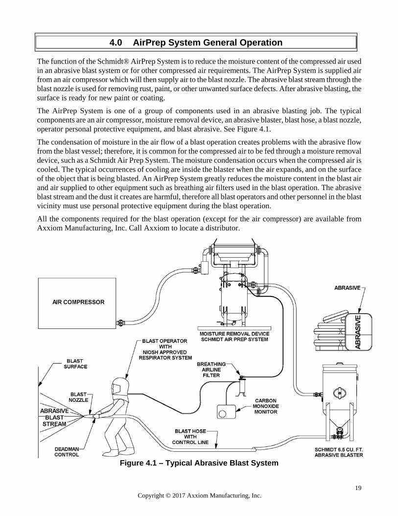
The function of the Schmidt® AirPrep System is to reduce the moisture content of the compressed air used in an abrasive blast system or for other compressed air requirements. The AirPrep System is supplied air from an air compressor which will then supply air to the blast nozzle. The abrasive blast stream through the blast nozzle is used for removing rust, paint, or other unwanted surface defects. After abrasive blasting, the surface is ready for new paint or coating. The AirPrep System is one of a group of components used in an abrasive blasting job. The typical components are an air compressor, moisture removal device, an abrasive blaster, blast hose, a blast nozzle, operator personal protective equipment, and blast abrasive. See Figure 4.1. The condensation of moisture in the air flow of a blast operation creates problems with the abrasive flow from the blast vessel; therefore, it is common for the compressed air to be fed through a moisture removal device, such as a Schmidt Air Prep System. The moisture condensation occurs when the compressed air is cooled. The typical occurrences of cooling are inside the blaster when the air expands, and on the surface of the object that is being blasted. An AirPrep System greatly reduces the moisture content in the blast air and air supplied to other equipment such as breathing air filters used in the blast operation. The abrasive blast stream and the dust it creates are harmful, therefore all blast operators and other personnel in the blast vicinity must use personal protective equipment during the blast operation. All the components required for the blast operation (except for the air compressor) are available from Axxiom Manufacturing, Inc. Call Axxiom to locate a distributor.
Figure 4.1 – Typical Abrasive Blast System
4.0 AirPrep System General Operation
20 Copyright © 2017 Axxiom Manufacturing, Inc.
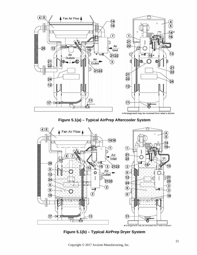
See Figure 5.1 to help understand the general operation of an AirPrep System. Do not attempt to operate the AirPrep System before reading all sections of this manual and following all setup procedures. See Sections 5.1 through 5.14 and Section 6.0. An AirPrep System is designed to cool, clean and dry compressed air for use in abrasive blasting equipment. The system removes moisture and contaminants that shorten the life of equipment controls and decrease blasting efficiency. Compressed air enters the AirPrep System at the pre-filter (#1) which filters trash and condensed moisture from the incoming air. The air flow then enters the aftercooler radiator (#4) where the flow is passed through a heat exchanger. The heat exchanger is constructed of many tubes through which the compressed air passes. Air flow created by the fan and air motor assembly (#5) is blown across the heat exchanger tubes which cools the compressed air. The cooling of the air condenses much of the moisture into water droplets. The cooled air and water droplets flow into the separator tank (#12) at the inlet. As the air flow rises through the tank it passes through stainless steel particulate filter (ACS Systems only) or a bed of marbles then into the deliquescent/desiccant tablets (ADS Systems only). The incoming air flow causes the condensed moisture to fall to the bottom of the vessel. The moisture collected is drained from the bottom of the separator tank through the drain valve (#11). The AirPrep fan air motor is turned on and off by the ball valve (#13). Closing the ball valve will disable the fan air motor (#5). The AirPrep System separator vessel (#12) is depressurized by closing the air compressor outlet ball valve and then opening the blowdown ball valve (#11) to completely vent the compressed air. 5.1 AirPrep System Air Inlet
The AirPrep System air inlet is located on the pre-filter (#1). The air inlet port is the same size as the aftercooler piping (see Section 2.7). On most models there are no fittings or ball valve provided for the air inlet. Only portable models include inlet/outlet ball valves and crowfeet. Any required fittings or ball valve must be provided by the owner/operator. Any valves, fittings or hoses installed on or connected to the AirPrep System air inlet port must have a minimum operating pressure of 150 psi.
Valve, fitting, and/or hose rupture can cause serious injury or death. Do Not install or connect any valves, fittings or hoses that are not rated for a minimum 150 psi operating pressure.
5.2 Pre-filter
Compressed air enters the system through the air inlet pre-filter (#1) (the maximum inlet pressure should not exceed 150 psi). The pre-filter removes large particle contaminants and moisture from the incoming air. The water and debris that is removed by the pre-filter can be drained through the drain valve (#3) located at the bottom of the pre-filter. This ball valve should be left slightly open anytime the system is in operation. This allows water to be drained as it is filtered from the air. Leave the drain valve (#3) closed anytime the AirPrep System is not in use.
5.3 Aftercooler Radiator After passing through the pre-filter, the air enters the aftercooler (#4). The aftercooler is a large fan cooled radiator that reduces the temperature of the compressed air which initiates moisture condensation. The fan is powered by either an air motor (#5) or an optional electric motor. Refer to Section 11.0 table 1 for the capacity of the aftercooler unit. The coil surfaces of the aftercooler radiator must be kept clean to maintain performance (see Section 8.0). CRITICAL: All AirPrep radiators include a 1/4" drain port plugged at the time of manufacture. When operating the system in an environment where freezing is possible install a ball valve in the radiator drain port to allow draining of accumulated water. This will protect against damage caused by inside water freezing.
5.0 AirPrep System General Operation
21 Copyright © 2017 Axxiom Manufacturing, Inc.
Figure 5.1(a) – Typical AirPrep Aftercooler System
Figure 5.1(b) – Typical AirPrep Dryer System
22 Copyright © 2017 Axxiom Manufacturing, Inc.
5.4 Air Motor (radiator fan) The air motor (#5) is a rotary type motor operated by compressed air. The expansion of the operating air during normal operation creates a cooling effect. Therefore, the temperature of the air motor will not exceed the higher of the surrounding atmosphere or the air input temperatures. The vanes of the air motor take up their own wear and will last 5,000-15,000 hours depending upon speed, method of oiling, operating pressure and the maintenance performed on the motor. The operating air must be clean, oiled and should not exceed the specified pressure; therefore, a filter/regulator and an automatic lubricator are installed in the air line upstream of the motor (refer to Section 11.0, Table 2 for air motor specifications). Ball valve (#13) turns off the air motor. Note: The air motor air supply must be clean, dry, and lubricated to minimize chance of motor failure.
5.5 Combination Air Filter/Regulator (fan air motor) The compressed air supplied to the air motor passes through an air filter/regulator (#14) to remove moisture which could cause rust in the air motor and also could cause ice to form on the exhaust muffler (#17). The water that is removed by the filter can be drained by opening the petcock valve at the bottom of the air filter. This valve should be left slightly opened anytime the system is in operation. This allows water to be drained as it is filtered from the air. Some models may be equipped with filters having automatic drains. The aftercooler fan speed can be controlled by changing the supply air pressure. The pressure is adjusted by turning the knob of the air filter/regulator (#14), clockwise to increase pressure/motor speed and counter-clockwise to decrease pressure/motor speed. The air pressure is indicated by the pressure gauge (#16) mounted on the regulator body. Note: The air motor pressure must not exceed the specified maximum pressure (see Section 11.0, Table 2).
5.6 Automatic Air Lubricator (fan air motor) After the air motor supply air passes the filter/regulator it is oiled by the automatic micro-fog lubricator (#15). The amount of lubrication depends on the volume of air passing through the motor. A detergent SAE #10 automotive engine oil is recommended; however SAE 10W-30 may be substituted. The lubricator flow rate is adjusted based upon the air cfm flow rate required for the air motor. Refer to Section 11.0, Table 2 for air flow and drip rate. The oil feed adjustment is made by turning the knob at the top of the lubricator, clockwise to increase flow or counter-clockwise to decrease flow. The lubricator reservoir can be drained if contaminants accumulate inside.
Failure to properly lubricate the air motor as detailed above will result in costly motor failure. Note: Filter/regulator and lubricator arrangement may vary from what is shown in Figure 5.1.
5.7 Electric Motor (radiator fan) Electric aftercooler fan motors (#5) are optional and are available in various operating voltages depending on the size of the aftercooler. The motor characteristics are on the nameplate attached to the motor (see to Section 11.0, Table 2 for motor specifications). The motor should be connected to a power source of the same characteristics as the motor. Be sure to provide proper overload protection to minimize chance of possible motor burnout. Verify the “as purchased” specification before installation and operation. Follow the manufacturer’s installation recommendations. Turn the fan by hand to eliminate possible motor burnout in the event the fan has been damaged in shipment. Observe operation after motor is started for the first time. See drawings in Section 9.0.
To protect against possible electrical shock, it is important to properly ground this unit using the grounding screw provided. Be sure not to disconnect the motor grounding wire when making this connection.
Power connections to AirPrep System with electric motors expose operators to high electrical voltages. Contact with high electrical voltages can result in serious injury or death. Only qualified personnel should install or perform maintenance on the electrical system.

23 Copyright © 2017 Axxiom Manufacturing, Inc.
Figure 5.1(a) – Typical AirPrep Aftercooler System
Figure 5.1(b) – Typical AirPrep Dryer System
24 Copyright © 2017 Axxiom Manufacturing, Inc.
5.8 Separator Tank After the compressed air leaves the aftercooler, it enters the separator tank (#12). The separator tank allows the compressed air to expand causing moisture condensation. The air enters the tank at a low elevation through a tangential inlet. The cyclonic movement causes the water droplets in the air to drop to the bottom of the tank. As the air flow rises through the tank it passes through a stainless steel particulate filter (ACS systems) or a bed of marbles (#10) then into the deliquescent/desiccant tablets (#9) (ADS Systems). The absorbed/adsorbed moisture then drops to the bottom of the separator tank. The moisture collected in the separator tank can be drained through the drain ball valve (#11). This ball valve should be left slightly open anytime the system is in operation. This allows water to be drained as it is filtered from the air. After each use the drain ball valve should be completely opened to drain all the moisture that has accumulated. The drain ball valve (#11) should be left closed anytime the unit is not in use.
The Air Prep System separator tank is a Pressurized Vessel. Propelled objects will cause serious injury or death. Depressurize vessel before performing any maintenance. See Section 6.2.
5.9 ACS System Air Outlets On ACS Aftercooler Systems the air outlets are located on the side of separator tank. There are five outlet ports; one primary outlet and four smaller auxiliary outlet ports. Portable models only have one outlet. Refer to Section 2.7 for the outlet sizes. Except for Portable models; there are no fittings or ball valves provided with the outlets. Any required fittings or ball valve should be provided by the user. Any valves, fittings or hoses installed on or connected to the AirPrep System air outlet ports must have a minimum operating pressure of 150 psi. Plug all outlet ports that are not used.
Valve, fitting, and/or hose rupture can cause serious injury or death. Do Not install or connect any valves, fittings or hoses that are not rated for a minimum 150 psi operating pressure.
5.10 Deliquescent/Desiccant Tablets (ADS Systems only) The volume of the ADS separator tank above the marble bed (#10) can be filled with deliquescent or desiccant tablets (#9). The tablets can be filled into the separator tank through the handway (#7) at the top. The deliquescent/desiccant tablets are not furnished with the AirPrep System. These materials are designed to lower the dew point of the compressed air by removing moisture. Deliquescent tablets absorb moisture and dissolve into a brine solution. Desiccant tablets adsorb moisture (adhesion to the contacting surface). The brine solution or water droplets then drop to the bottom of the separator tank. The moisture or brine solution can be drained through the ball valve (#11) at the bottom of the tank. Note: Keep all drains and outlet valves closed anytime the AirPrep System is not in use. This is to protect against moist air entering from outside of the system. Note: ACS Systems are not designed for use of deliquescent/desiccant.
The Air Prep System is a Pressurized Vessel. Propelled objects will cause serious injury or death. Depressurize vessel before performing any maintenance. See Section 6.2.
5.11 After-Filter (ADS Systems only) The particulate after-filter (#2) removes particles of deliquescent or desiccant material that may have been carried over from the separator tank. The after-filter also is the air source for the aftercooler air motor. Any debris that is removed by the after-filter can be drained through the drain valve (#3) located at the bottom of the after-filter. The drain ball valve (#3) should be left closed anytime the AirPrep System is not in use.
25 Copyright © 2017 Axxiom Manufacturing, Inc.
5.12 ADS System Air Outlets On ADS Dryer Systems the air outlets are located on the after-filter (#2). There are three outlet ports; one primary outlet and two smaller auxiliary ports. Portable models only have one air outlet. Refer to Section 2.8 for the outlet sizes. There are no fittings or ball valves provided with the outlets. Any required fittings or ball valve should be provided by the user. Any valves, fittings or hoses installed on or connected to the AirPrep System air outlet ports must have a minimum operating pressure of 150 psi. Plug all outlet ports that are not used.
Valve, fitting, and/or hose rupture can cause serious injury or death. Do Not install or connect any valves, fittings or hoses that are not rated for a minimum 150 psi operating pressure.
5.11 Depressurize (Blowdown)
The drain ball valve (#11) is used to release all the compressed air (depressurize) from inside the AirPrep System separator tank (#12). The AirPrep System must be depressurized for filling with deliquescent /desiccant tablets (ADS Systems), or to perform any maintenance. To depressurize the separator tank turn off the air compressor and/or close the compressor’s outlet valve, then slowly open the drain ball valve (#11) located at the bottom of the tank (see Section 6.2). The drain ball valve should be left closed anytime the unit in not in use. If the ADS System drain ball valve is left open deliquescent/desiccant tablets will remove moisture from air entering from outside the tank.
Airborne particles and loud noise hazards from blowdown exhaust air can cause serious injury and loss of hearing. Wear approved eye and ear protection. Stay clear of blowdown air path. DO NOT place hands or other body parts in the blowdown air path. Make sure no personnel are in the blowdown air path.
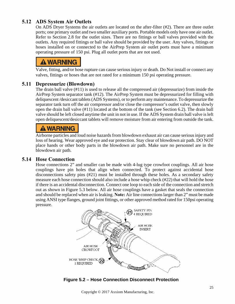
5.14 Hose Connection
Hose connections 2” and smaller can be made with 4-lug type crowfoot couplings. All air hose couplings have pin holes that align when connected. To protect against accidental hose disconnections safety pins (#21) must be installed through these holes. As a secondary safety measure each hose connection should also include a hose whip check (#22) that will hold the hose if there is an accidental disconnection. Connect one loop to each side of the connection and stretch out as shown in Figure 5.3 below. All air hose couplings have a gasket that seals the connection and should be replaced when air is leaking. Note: Air line connections larger than 2” must be made using ANSI type flanges, ground joint fittings, or other approved method rated for 150psi operating pressure.
Figure 5.2 – Hose Connection Disconnect Protection
26 Copyright © 2017 Axxiom Manufacturing, Inc.
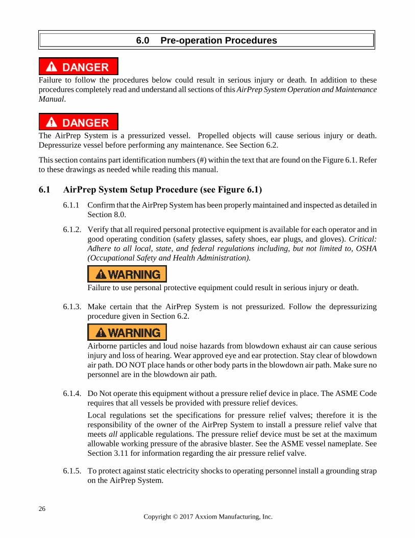
Failure to follow the procedures below could result in serious injury or death. In addition to these procedures completely read and understand all sections of this AirPrep System Operation and Maintenance Manual.
The AirPrep System is a pressurized vessel. Propelled objects will cause serious injury or death. Depressurize vessel before performing any maintenance. See Section 6.2. This section contains part identification numbers (#) within the text that are found on the Figure 6.1. Refer to these drawings as needed while reading this manual. 6.1 AirPrep System Setup Procedure (see Figure 6.1)
6.1.1 Confirm that the AirPrep System has been properly maintained and inspected as detailed in Section 8.0.
6.1.2. Verify that all required personal protective equipment is available for each operator and in
good operating condition (safety glasses, safety shoes, ear plugs, and gloves). Critical: Adhere to all local, state, and federal regulations including, but not limited to, OSHA (Occupational Safety and Health Administration).
Failure to use personal protective equipment could result in serious injury or death.
6.1.3. Make certain that the AirPrep System is not pressurized. Follow the depressurizing procedure given in Section 6.2.
Airborne particles and loud noise hazards from blowdown exhaust air can cause serious injury and loss of hearing. Wear approved eye and ear protection. Stay clear of blowdown air path. DO NOT place hands or other body parts in the blowdown air path. Make sure no personnel are in the blowdown air path.
6.1.4. Do Not operate this equipment without a pressure relief device in place. The ASME Code
requires that all vessels be provided with pressure relief devices. Local regulations set the specifications for pressure relief valves; therefore it is the responsibility of the owner of the AirPrep System to install a pressure relief valve that meets all applicable regulations. The pressure relief device must be set at the maximum allowable working pressure of the abrasive blaster. See the ASME vessel nameplate. See Section 3.11 for information regarding the air pressure relief valve.
6.1.5. To protect against static electricity shocks to operating personnel install a grounding strap on the AirPrep System.
6.0 Pre-operation Procedures
27 Copyright © 2017 Axxiom Manufacturing, Inc.
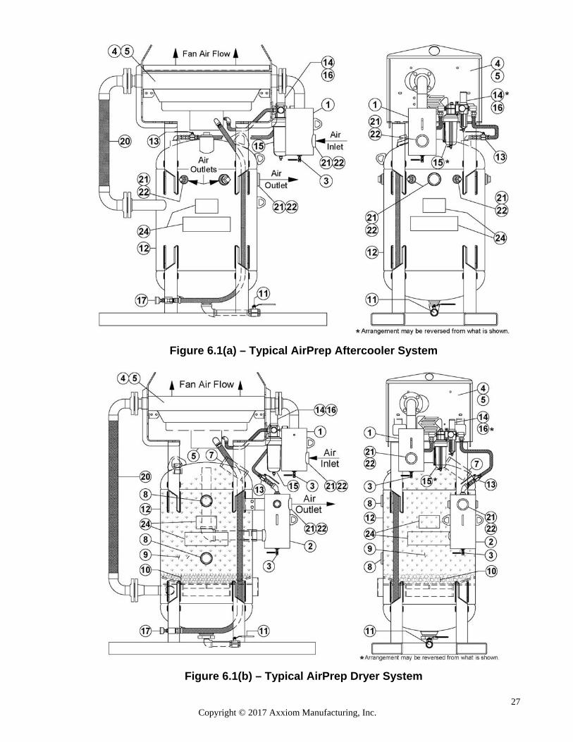
Figure 6.1(a) – Typical AirPrep Aftercooler System
Figure 6.1(b) – Typical AirPrep Dryer System

28 Copyright © 2017 Axxiom Manufacturing, Inc.
6.1.6. Units having electric aftercooler fan motors must be installed by qualified personnel. Follow manufacturer’s recommendations.
Power connections to AirPrep System with electric motors expose operators to high electrical voltages. Contact with high electrical voltages can result in serious injury or death. Only qualified personnel should install or perform maintenance on the electrical system.
6.1.7. Open drain valves (#3) on the pre-filter (#1) and after-filter (#2), petcock valve (#14) (units
with air motor) and drain valve (#11) on the separator tank to drain out moisture inside. Note: These drain valves should be left closed when the unit is not in use.
6.1.8. Close drain valves (#3), (#11) and petcock valve (#14).
6.1.9. Close all the air outlet ball valve(s) (provided by user).
6.1.10. If the unit has an electric aftercooler motor skip to 6.1.13. If the aftercooler has an air
motor, close the air motor on/off ball valve (#13).
6.1.11. Check the reservoir of the air lubricator (#15) for debris in the oil. If necessary drain the oil through the petcock valve at the bottom of the bowl. Fill the oil reservoir of the automatic air lubricator (#15) with detergent SAE #10 automotive engine oil. Lubricator adjustment is detailed in Sections 5.6 and 7.2. Note: Filter/regulator and lubricator arrangement may vary from what is shown in Figure 6.1.
6.1.12. Tighten the bowls on air filter (#14) and air lubricator (#15).
6.1.13. Check the level of the deliquescent/desiccant tablets (#9). Fill if necessary, through the
upper handway opening (#7). (ADS Systems only)
6.1.14. Properly install the handway (#7) on the separator tank (#12). See Section 6.3.
6.1.15. Turn the aftercooler fan (#4) by hand to be sure that no damage has occurred to fan during shipment or time of non-use. This will eliminate possible motor burnout.
6.1.16. Connect an air supply hose to the air inlet on the pre-filter (#1) and install safety clips to
protect against accidental disconnections during operation.
Failure to install safety pins on all hose couplings could result in serious injury or death. See Sections 5.1, 5.14, and 8.8.
6.1.17. Connect output air supply hose(s) to the outlet connections on the separator tank (#12) (ACS Systems) or the after-filter (#2) (ADS Systems) and install safety clips (#21) and hose whip checks (#22) to protect against accidental disconnections during operation. See Sections 5.1, 5.14, and 8.8.
Failure to install safety pins and whip checks on all hose couplings could result in serious injury or death. See Sections 5.1, 5.14, and 8.8.
29 Copyright © 2017 Axxiom Manufacturing, Inc.
6.2 AirPrep System Depressurizing Procedure (Blowdown)
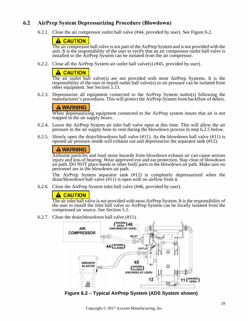
6.2.1. Close the air compressor outlet ball valve (#44, provided by user). See Figure 6.2.
The air compressor ball valve is not part of the AirPrep System and is not provided with the unit. It is the responsibility of the user to verify that an air compressor outlet ball valve is installed so the AirPrep System can be isolated from the air compressor.
6.2.2. Close all the AirPrep System air outlet ball valve(s) (#45, provided by user).
The air outlet ball valve(s) are not provided with most AirPrep Systems. It is the responsibility of the user to install outlet ball valve(s) so air pressure can be isolated from other equipment. See Section 5.13.
6.2.3. Depressurize all equipment connected to the AirPrep System outlet(s) following the manufacturer’s procedures. This will protect the AirPrep System from backflow of debris.
When depressurizing equipment connected to the AirPrep system insure that air is not trapped in the air supply hoses.
6.2.4. Leave the AirPrep System air inlet ball valve open at this time. This will allow the air
pressure in the air supply hose to vent during the blowdown process in step 6.2.5 below. 6.2.5. Slowly open the drain/blowdown ball valve (#11). As the blowdown ball valve (#11) is
opened air pressure inside will exhaust out and depressurize the separator tank (#12).
Airborne particles and loud noise hazards from blowdown exhaust air can cause serious injury and loss of hearing. Wear approved eye and ear protection. Stay clear of blowdown air path. DO NOT place hands or other body parts in the blowdown air path. Make sure no personnel are in the blowdown air path. The AirPrep System separator tank (#12) is completely depressurized when the drain/blowdown ball valve (#11) is open with no airflow from it.
6.2.6. Close the AirPrep System inlet ball valve (#46, provided by user).
The air inlet ball valve is not provided with most AirPrep System. It is the responsibility of the user to install the inlet ball valve so AirPrep System can be locally isolated from the compressed air source. See Section 5.1.
6.2.7. Close the drain/blowdown ball valve (#11).
Figure 6.2 – Typical AirPrep System (ADS System shown)
30 Copyright © 2017 Axxiom Manufacturing, Inc.
6.3 Handway Cover Installation Procedures (See Figure 6.3(a))
6.4.1. Check that the handway cover, crab, bolt, and gasket are dimensionally correct for the size handway weld ring of the pressure vessel.
a) Measure and write down the inside dimensions “A” and “B” of the handway weld ring.
See Figure 6.4(a).
b) Verify the size of the handway assembly by comparing the weld ring measurements from step “a” to the dimensions shown in Table 6.4(c).
c) Verify that the dimensions of the cover, crab, bolt, and gasket match the corresponding
dimensions given in Table 6.4(c). Note: The actual dimensions may vary by up to 1/4" from those given in Table 6.4(c).
d) Replace any component that is not dimensionally correct. Incorrect dimensions indicate
that the component is part of a different size handway assembly.
The handway assembly is part of a Pressurized Vessel. Use of incorrect handway components will result in assembly failure. Assembly failure will propel objects causing serious injury or death.
6.4.2. Once a month inspect the handway gasket for tears, cracks, or other wear. Replace if
necessary.
6.4.3. Once a month inspect the handway weld ring sealing surface inside the vessel. Inspect the handway cover sealing surface. Both surfaces must be smooth.
6.4.4. Place the gasket on the handway cover then fit both through the opening.
6.4.5. Place the cover and gasket in position against the inside edge of the handway weld ring.
Apply a pulling force to hold in position then proceed. *See note below.
6.4.6. Center the gasket on the handway weld ring.
6.4.7. Center the handway cover on the gasket.
6.4.8. Center the handway crab on the outside weld ring.
6.4.9. Slide the handway crab bolt to the inside edge of the slot before tightening. See Figure 6.4(a).
6.4.10. When all components are centered and the crab bolt is bottomed in the slot, tighten the nut
onto the bolt with a wrench until snug.
6.4.11. Only after completing all the pre-operation procedures in Section 6.0 and the abrasive blast vessel is then pressurized, re-tighten the nut with a wrench until snug again.
6.4.12. Do not over-tighten the crab nut and bolt. Over-tightening could bend the crab out of shape
resulting in malfunction of the assembly.
6.3.13. Periodically check for leaks.
*Note: Contact Axxiom Manufacturing or an Authorized Schmidt distributor and request information on the new SureFit™ Handway Gasket (patent pending) that eliminates the difficulty of aligning the gasket. Scan the QR Tag on the left to view a short video.
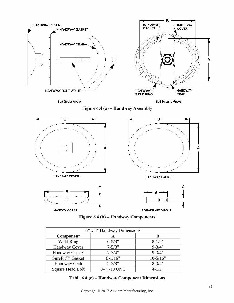
31 Copyright © 2017 Axxiom Manufacturing, Inc.
Figure 6.4 (a) – Handway Assembly
Figure 6.4 (b) – Handway Components
6” x 8” Handway Dimensions Component A B Weld Ring 6-5/8” 8-1/2”
Handway Cover 7-5/8” 9-3/4” Handway Gasket 7-3/4” 9-3/4” SureFit™ Gasket 8-1/16” 10-5/16” Handway Crab 2-3/8” 8-3/4”
Square Head Bolt 3/4”-10 UNC 4-1/2”
Table 6.4 (c) – Handway Component Dimensions
32 Copyright © 2017 Axxiom Manufacturing, Inc.
7.1 Filling the AirPrep Air Dryer System With Deliquescent/Desiccant (ADS Systems only)
7.1.1. The AirPrep ADS System must be completely depressurized before filling with deliquescent can begin. Follow the depressurizing procedure in Section 6.2.
Airborne particles and loud noise hazards from blowdown exhaust air can cause serious injury and loss of hearing. Wear approved eye and ear protection. Stay clear of blowdown air path. DO NOT place hands or other body parts in the blowdown air path. Make sure no personnel are in the blowdown air path.
7.1.2. Open the pre-filter (#1) drain ball valve (#3) to check for air flow. No air flow indicates that
the AirPrep System is depressurized. See Figure 7.1(b).
7.1.3. Remove the handway cover (#7) at the top of the separator tank (#12). 7.1.4. Check inside the separator tank for looseness of the deliquescent/desiccant tablets (#9).
Extended exposure to moisture will fuse the tablets together and can possibly block or restrict air flow. Break apart fused tablets with a long rod or similar device. Fill with tablets to the top of the separator tank (#12).
7.1.5. Re-install the handway cover and gasket (#7). See Section 6.3 for installation procedure.
7.1.6. Only after completing all the pre-operation procedures in Sections 6.0 and 7.1, and the
AirPrep System is then pressurized per Section 7.2, check the handway(s) (#7) for leaks. Periodically check the handway(s) for leaks thereafter.
7.2 AirPrep System Startup (refer to Figure 7.1)
7.2.1. The AirPrep System must be properly prepared and all operating personnel must be thoroughly trained before operation. Completely read and understand all sections of this manual before beginning operation. See the pre-operation procedures given in Section 6.0.
7.2.2. Perform the required inspections and maintenance before beginning AirPrep System
operation. See the instructions given in Section 8.0.
The AirPrep System is a Pressurized Vessel. Propelled objects will cause serious injury or death. Depressurize vessel before performing any maintenance. See Section 6.2.
7.2.3. Supply air to the AirPrep System by starting the air compressor and opening the compressor's air outlet valve (#44).
7.2.4. Open the AirPrep System air inlet ball valve (#46). Note: This valve is provided by the
equipment owner/operator and filed installed. See Figure 6.2 and Section 5.1.
7.2.5. Slightly open drain valves (#3), (#11) and petcock valve (#14) (units with air motor) so that moisture/debris can be drained from the pre-filter, after-filter, separator tank, and air filter as it is removed from the compressed air.
7.0 Operating Instructions
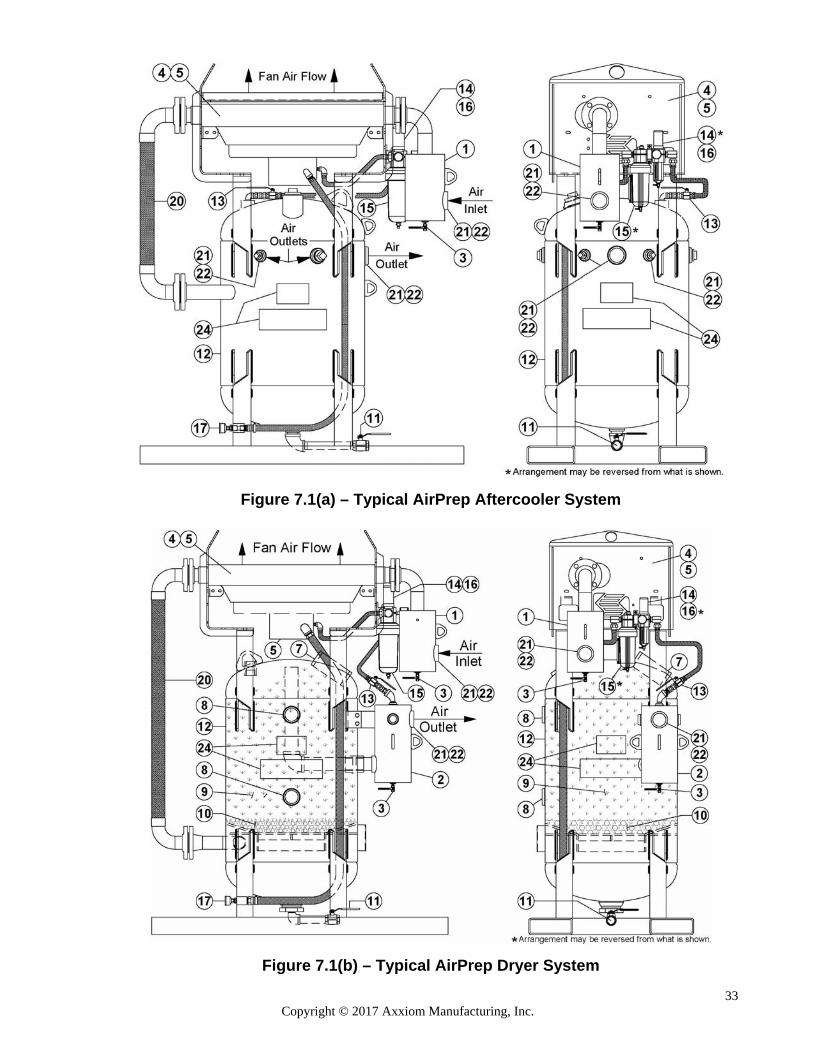
33 Copyright © 2017 Axxiom Manufacturing, Inc.
Figure 7.1(a) – Typical AirPrep Aftercooler System
Figure 7.1(b) – Typical AirPrep Dryer System
34 Copyright © 2017 Axxiom Manufacturing, Inc.
7.2.5. If the unit has an electric aftercooler motor, press the “Start” button to begin cooling fan operation, then skip to step 7.2.8. If the aftercooler has an air motor, open the air motor on/off ball valve (#13).
7.2.6. Adjust air pressure regulator (#14) to the required pressure. See Section 11.0 for correct air
motor inlet pressure setting. Turn clockwise to increase pressure/motor speed and counter-clockwise to decrease pressure/motor speed.
Do not exceed maximum air motor pressure. Exceeding the air motor operating pressure can cause system failure. See Section 11.0, Table 2 for air motor operating pressure.
7.2.7. Adjust the lubricator (#15) to the proper flow rate. The lubricator flow rate is adjusted
based upon the air cfm flow rate required for the air motor. Refer to Section 11.0, Table 2 for air flow and drip rate requirement. Turn the socket head screw on top of the lubricator to adjust flow (clockwise to increase flow, counterclockwise to decrease flow). See Section 5.6.
Failure to lubricate the air motor will result in motor failure. See Section 11.0, Table 2 for air motor cfm requirements. Note: Filter/regulator and lubricator arrangement may vary from what is shown in Figure 7.1(a) and 7.1(b).
7.2.8. Confirm that the aftercooler fan rotation is correct. The airflow should be up through the radiator (#4). Incorrect air flow indicates the air motor (#5) air supply and exhaust ports are reversed. On units with electric fan motors electrical changes are required. Consult a qualified electrician.
7.2.9. Open outlet ball valve(s) (#45) to supply air to the connected equipment (see Figure 6.2).
7.3 AirPrep System Shutdown
7.3.1 Close the aftercooler motor air supply valve (#13). On electric units press the “Stop” button on the motor starter control box to end cooling fan operation.
7.3.2 Close all the AirPrep System air outlet ball valves (see Figure 6.2).
7.3.3 Turn off the air compressor and/or close the compressor’s outlet valve (see Figure 6.2).
7.3.4 Open drain valve (#3) on the pre-filter (#1), after-filter (#2) and petcock valve (#1) (units
with air motor) to drain moisture and clean out dirt particles.
7.3.5 Completely depressurize the AirPrep System separator tank (#12) by slowly and completely opening the blowdown ball valve (#11). See Section 6.2 for blowdown procedure.
Airborne particles and loud noise hazard from the blowdown exhaust air can cause serious injury and loss of hearing. Wear approved eye and ear protection. Stay clear of blowdown air path. DO NOT place hands or other body parts in the blowdown air path. Make sure no personnel are in the blowdown air path.
7.3.6 Close drain valves (#3), (#14), and petcock valve (#11).

35 Copyright © 2017 Axxiom Manufacturing, Inc.
Figure 7.1(a) – Typical AirPrep Aftercooler System
Figure 7.1(b) – Typical AirPrep Dryer System
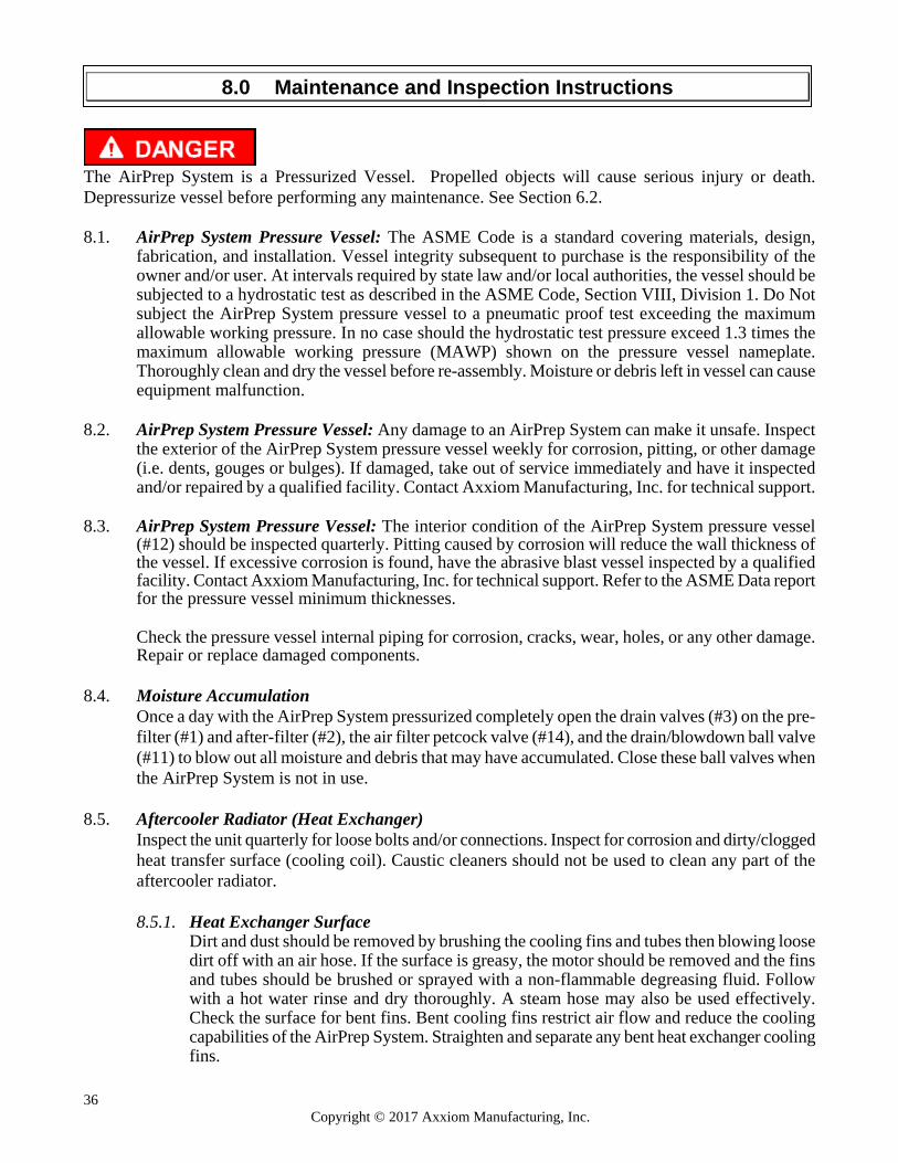
36 Copyright © 2017 Axxiom Manufacturing, Inc.
The AirPrep System is a Pressurized Vessel. Propelled objects will cause serious injury or death. Depressurize vessel before performing any maintenance. See Section 6.2. 8.1. AirPrep System Pressure Vessel: The ASME Code is a standard covering materials, design,
fabrication, and installation. Vessel integrity subsequent to purchase is the responsibility of the owner and/or user. At intervals required by state law and/or local authorities, the vessel should be subjected to a hydrostatic test as described in the ASME Code, Section VIII, Division 1. Do Not subject the AirPrep System pressure vessel to a pneumatic proof test exceeding the maximum allowable working pressure. In no case should the hydrostatic test pressure exceed 1.3 times the maximum allowable working pressure (MAWP) shown on the pressure vessel nameplate. Thoroughly clean and dry the vessel before re-assembly. Moisture or debris left in vessel can cause equipment malfunction.
8.2. AirPrep System Pressure Vessel: Any damage to an AirPrep System can make it unsafe. Inspect
the exterior of the AirPrep System pressure vessel weekly for corrosion, pitting, or other damage (i.e. dents, gouges or bulges). If damaged, take out of service immediately and have it inspected and/or repaired by a qualified facility. Contact Axxiom Manufacturing, Inc. for technical support.
8.3. AirPrep System Pressure Vessel: The interior condition of the AirPrep System pressure vessel
(#12) should be inspected quarterly. Pitting caused by corrosion will reduce the wall thickness of the vessel. If excessive corrosion is found, have the abrasive blast vessel inspected by a qualified facility. Contact Axxiom Manufacturing, Inc. for technical support. Refer to the ASME Data report for the pressure vessel minimum thicknesses.
Check the pressure vessel internal piping for corrosion, cracks, wear, holes, or any other damage.
Repair or replace damaged components. 8.4. Moisture Accumulation
Once a day with the AirPrep System pressurized completely open the drain valves (#3) on the pre-filter (#1) and after-filter (#2), the air filter petcock valve (#14), and the drain/blowdown ball valve (#11) to blow out all moisture and debris that may have accumulated. Close these ball valves when the AirPrep System is not in use.
8.5. Aftercooler Radiator (Heat Exchanger)
Inspect the unit quarterly for loose bolts and/or connections. Inspect for corrosion and dirty/clogged heat transfer surface (cooling coil). Caustic cleaners should not be used to clean any part of the aftercooler radiator.
8.5.1. Heat Exchanger Surface
Dirt and dust should be removed by brushing the cooling fins and tubes then blowing loose dirt off with an air hose. If the surface is greasy, the motor should be removed and the fins and tubes should be brushed or sprayed with a non-flammable degreasing fluid. Follow with a hot water rinse and dry thoroughly. A steam hose may also be used effectively. Check the surface for bent fins. Bent cooling fins restrict air flow and reduce the cooling capabilities of the AirPrep System. Straighten and separate any bent heat exchanger cooling fins.
8.0 Maintenance and Inspection Instructions
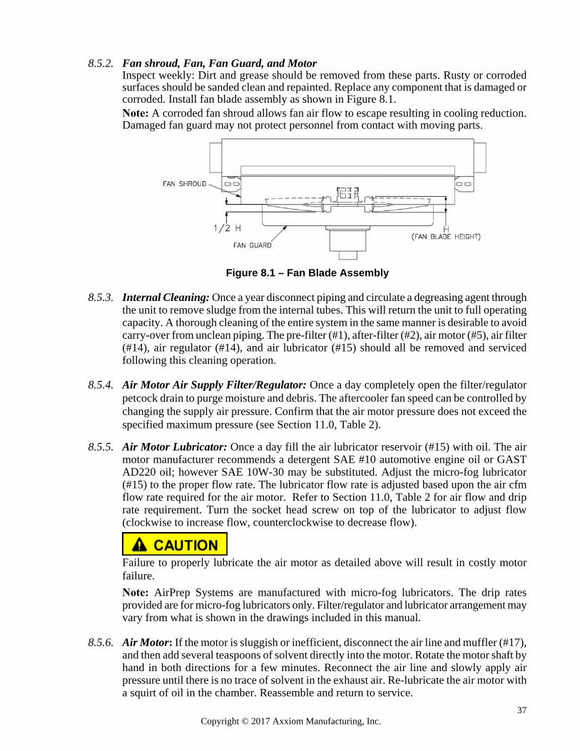
37 Copyright © 2017 Axxiom Manufacturing, Inc.
8.5.2. Fan shroud, Fan, Fan Guard, and Motor
Inspect weekly: Dirt and grease should be removed from these parts. Rusty or corroded surfaces should be sanded clean and repainted. Replace any component that is damaged or corroded. Install fan blade assembly as shown in Figure 8.1. Note: A corroded fan shroud allows fan air flow to escape resulting in cooling reduction. Damaged fan guard may not protect personnel from contact with moving parts.
Figure 8.1 – Fan Blade Assembly
8.5.3. Internal Cleaning: Once a year disconnect piping and circulate a degreasing agent through
the unit to remove sludge from the internal tubes. This will return the unit to full operating capacity. A thorough cleaning of the entire system in the same manner is desirable to avoid carry-over from unclean piping. The pre-filter (#1), after-filter (#2), air motor (#5), air filter (#14), air regulator (#14), and air lubricator (#15) should all be removed and serviced following this cleaning operation.
8.5.4. Air Motor Air Supply Filter/Regulator: Once a day completely open the filter/regulator petcock drain to purge moisture and debris. The aftercooler fan speed can be controlled by changing the supply air pressure. Confirm that the air motor pressure does not exceed the specified maximum pressure (see Section 11.0, Table 2).
8.5.5. Air Motor Lubricator: Once a day fill the air lubricator reservoir (#15) with oil. The air
motor manufacturer recommends a detergent SAE #10 automotive engine oil or GAST AD220 oil; however SAE 10W-30 may be substituted. Adjust the micro-fog lubricator (#15) to the proper flow rate. The lubricator flow rate is adjusted based upon the air cfm flow rate required for the air motor. Refer to Section 11.0, Table 2 for air flow and drip rate requirement. Turn the socket head screw on top of the lubricator to adjust flow (clockwise to increase flow, counterclockwise to decrease flow).
Failure to properly lubricate the air motor as detailed above will result in costly motor failure. Note: AirPrep Systems are manufactured with micro-fog lubricators. The drip rates provided are for micro-fog lubricators only. Filter/regulator and lubricator arrangement may vary from what is shown in the drawings included in this manual.
8.5.6. Air Motor: If the motor is sluggish or inefficient, disconnect the air line and muffler (#17), and then add several teaspoons of solvent directly into the motor. Rotate the motor shaft by hand in both directions for a few minutes. Reconnect the air line and slowly apply air pressure until there is no trace of solvent in the exhaust air. Re-lubricate the air motor with a squirt of oil in the chamber. Reassemble and return to service.
38 Copyright © 2017 Axxiom Manufacturing, Inc.
8.5.7 Air Motor Exhaust Muffler: Inspect the air motor exhaust muffler monthly. Dirt and grime accumulation on the exhaust element can restrict air flow and cause a reduction of power output from the air motor. Remove the muffler and clean with a degreasing agent.
8.5.8. Electric Motor
Keep outside surface free of dirt and grease so motor will cool properly. Make sure cooling air over motor is not obstructed. The motors are normally furnished with sealed bearing that do not require maintenance. However if the motor is equipped with an Alemite fitting, clean the tip and apply grease gun. Use 1 to 2 full strokes on motors in NEMA 215 frame and smaller, 2 to 3 strokes on NEMA 254 through 365 frame and 3 to 4 strokes on NEMA 404 frames and larger. On motors having drain plugs, remove grease drain plug and operate motor for 20 minutes before replacing drain plug. Refer to motor nameplate. Motors furnished with ball bearings require lubrication every 6 months.
Electric Shock Hazard. Disconnect electric power to motor before performing any routine maintenance.
Electric Shock Hazard. Power connections to AirPrep System with electric motors expose operators to high electrical voltages. Contact with high electrical voltages can result in serious injury or death. Only qualified personnel should install or perform maintenance on the electrical system.
8.6 Separator Tank Deliquescent/Desiccant (ADS Systems Only) Check the deliquescent/desiccant level monthly. At each filling of deliquescent/desiccant check inside the separator tank for looseness of the deliquescent/desiccant tablets (#9). Extended exposure to moisture will fuse the tablets together and can possibly block or restrict air flow. Break apart fused tablets with a long rod or similar device. Fill with tablets to the top of the separator tank (#12). Note: Minimum tablet size is 5/8” x 3/4". Smaller sizes will reduce air flow through marble bed (#10).
8.7. Blast and Air Hoses, Piping, Pipe Fittings, and Wires: All air hoses, blast hoses, control hoses,
pipe, pipe fittings, and wires are wear items on any abrasive blaster. These components should be inspected daily for air leaks, cracks, holes, dry rotting, cuts, or any other damage. Repair or replace any components that show any signs of wear or damage.
Damaged hoses, piping, pipe fittings or wires can cause system malfunctions and can result in serious injury or death to operating personnel.
Worn hose assemblies can rupture during operation and the resulting pressurized air stream can cause serious personal injury.
Static electric shock hazard. To minimize the chance of static electric shock install a grounding strap on the AirPrep System and only use static dissipating hoses.
39 Copyright © 2017 Axxiom Manufacturing, Inc.
8.8. Blast/Air Hose Couplings: All air hose couplings have pin holes that align when connected. To protect against accidental hose disconnections safety pins must be installed through these holes. Each hose connection must also include a hose whip check that will hold the hose if there is an accidental disconnection. Connect one loop to each side of the connection and stretch out as shown in Figure 8.2 below. Check hose connections daily and replace missing or damaged pins and whip checks.
Failure to install safety pins and whip checks on all hose couplings could result in serious injury or death.
Figure 8.2 – Hose Connection Disconnect Protection
8.9 Blast and Air Hose Gaskets: All air hose, blast hose, and threaded couplings have gaskets that seal
the connection. To reduce loss of air pressure and/or premature abrasive wear replace these gaskets when leaks are found. Inspect the couplings daily for leaks and wear. Replace gaskets when visible wear or leaks are found. To insure proper coupling connection always use fittings that are the same brand. See the drawings and part lists in Section 9.0.
8.10. Personal Protective Equipment: Check daily to verify that all personal protective equipment is
available for each blast operator. Check daily to verify that all personal protective equipment is in good operating condition. Consult the operating and maintenance instructions provided by the manufacturer of each PPE item. See Section 3.10 and reference OSHA 29 CFR 1910 Subpart I.
Failure to use personal protective equipment could result in serious injury or death.
8.11. Warning Decals: Check monthly to verify that all the warning decals are in position and legible. See Section 0.0 for full descriptions and locations.
Failure to maintain warning decals risks the possibility of not alerting the AirPrep System operator to potential dangers which can result in serious injury or death. See Section 0.0.
8.12. Handway Assembly (ADS Systems only, except portable models): Refer to Section 6.3 for installation and inspection procedures.
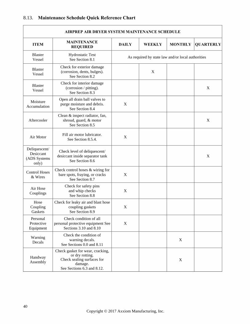
40 Copyright © 2017 Axxiom Manufacturing, Inc.
8.13. Maintenance Schedule Quick Reference Chart
AIRPREP AIR DRYER SYSTEM MAINTENANCE SCHEDULE
ITEM MAINTENANCE
REQUIRED DAILY WEEKLY MONTHLY QUARTERLY
Blaster Vessel
Hydrostatic Test See Section 8.1
As required by state law and/or local authorities
Blaster Vessel
Check for exterior damage (corrosion, dents, bulges).
See Section 8.2 X
Blaster Vessel
Check for interior damage (corrosion / pitting).
See Section 8.3 X
Moisture Accumulation
Open all drain ball valves to purge moisture and debris.
See Section 8.4 X
Aftercooler Clean & inspect radiator, fan,
shroud, guard, & motor See Section 8.5
X
Air Motor Fill air motor lubricator.
See Section 8.5.4. X
Deliquescent/ Desiccant
(ADS Systems only)
Check level of deliquescent/ desiccant inside separator tank
See Section 8.6 X
Control Hoses & Wires
Check control hoses & wiring for bare spots, fraying, or cracks
See Section 8.7 X
Air Hose Couplings
Check for safety pins and whip checks See Section 8.8
X
Hose Coupling Gaskets
Check for leaky air and blast hose coupling gaskets See Section 8.9
X
Personal Protective Equipment
Check condition of all personal protective equipment See
Sections 3.10 and 8.10 X
Warning Decals
Check the condition of warning decals.
See Sections 0.0 and 8.11 X
Handway Assembly
Check gasket for wear, cracking, or dry rotting.
Check sealing surfaces for damage.
See Sections 6.3 and 8.12.
X
41 Copyright © 2017 Axxiom Manufacturing, Inc.
The following pages contain drawings representing typical
blast control systems and components. Determine the type of
control system the abrasive blast system is equipped with
(pneumatic or electric controls) then reference the
appropriate drawing and parts list to determine the required
parts. To insure the proper operation of the AirPrep System
only use Schmidt® original factory replacement parts
furnished by an authorized Schmidt distributor. See Section
1.37 and Section 12.2.12.
9.0 Drawings and Parts Lists
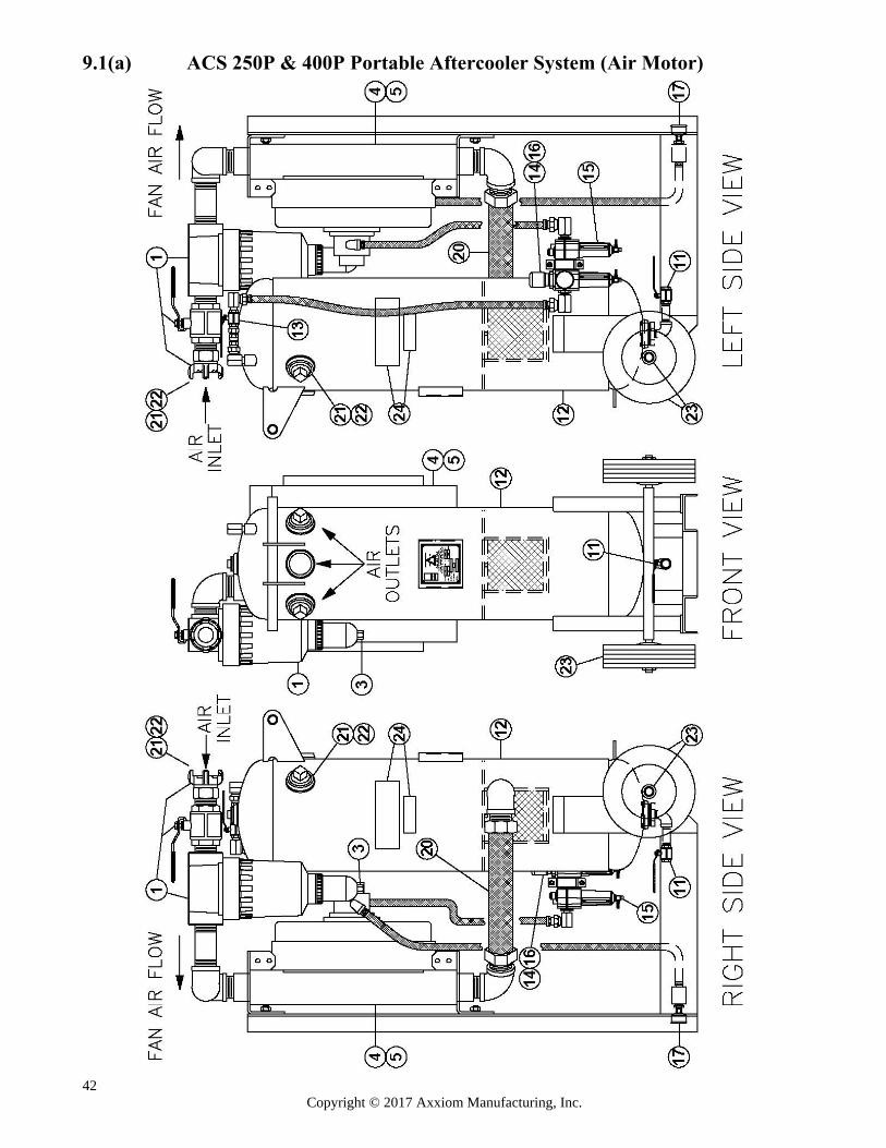
42 Copyright © 2017 Axxiom Manufacturing, Inc.
9.1(a) ACS 250P & 400P Portable Aftercooler System (Air Motor)
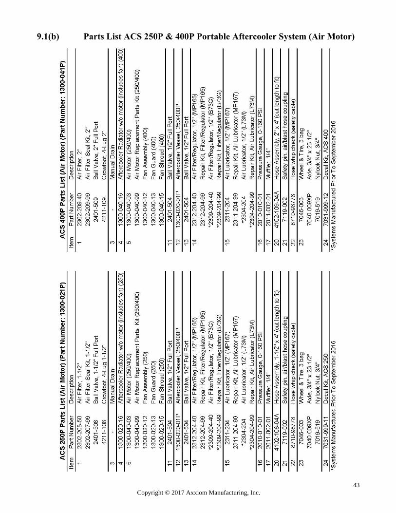
43 Copyright © 2017 Axxiom Manufacturing, Inc.
9.1(b) Parts List ACS 250P & 400P Portable Aftercooler System (Air Motor)
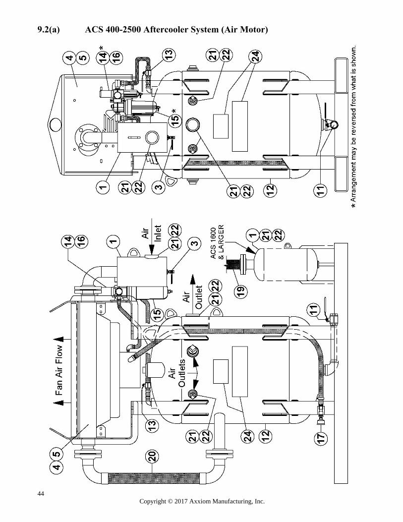
44 Copyright © 2017 Axxiom Manufacturing, Inc.
9.2(a) ACS 400-2500 Aftercooler System (Air Motor)
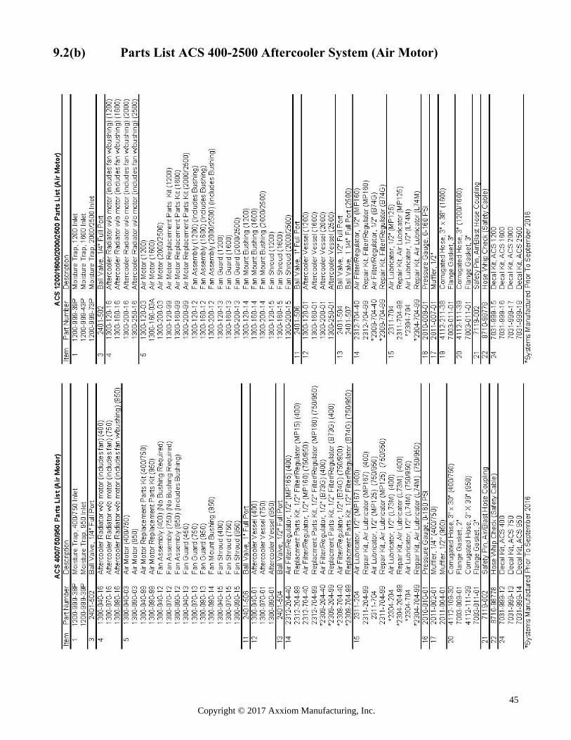
45 Copyright © 2017 Axxiom Manufacturing, Inc.
9.2(b) Parts List ACS 400-2500 Aftercooler System (Air Motor)
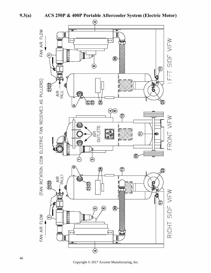
46 Copyright © 2017 Axxiom Manufacturing, Inc.
9.3(a) ACS 250P & 400P Portable Aftercooler System (Electric Motor)
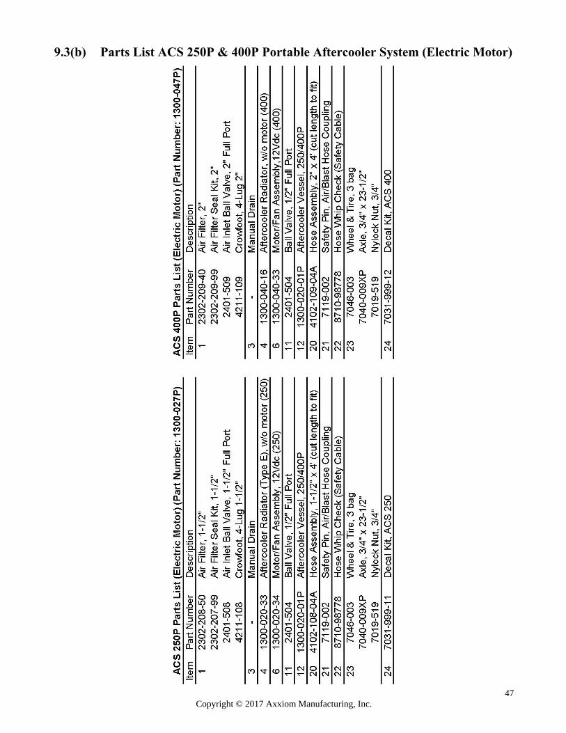
47 Copyright © 2017 Axxiom Manufacturing, Inc.
9.3(b) Parts List ACS 250P & 400P Portable Aftercooler System (Electric Motor)
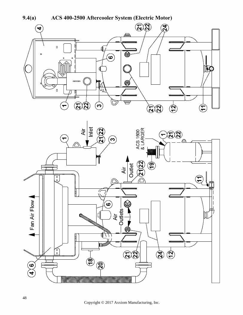
48 Copyright © 2017 Axxiom Manufacturing, Inc.
9.4(a) ACS 400-2500 Aftercooler System (Electric Motor)
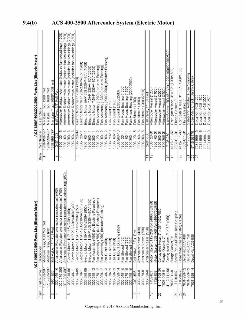
49 Copyright © 2017 Axxiom Manufacturing, Inc.
9.4(b) ACS 400-2500 Aftercooler System (Electric Motor)
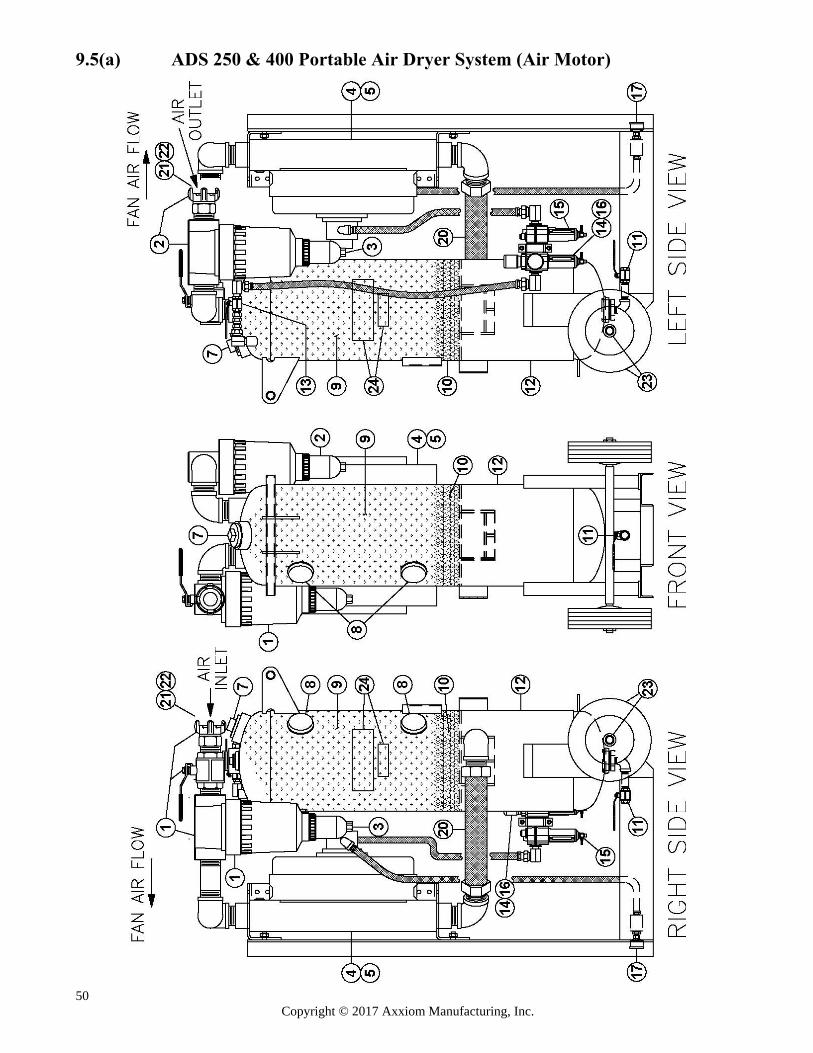
50 Copyright © 2017 Axxiom Manufacturing, Inc.
9.5(a) ADS 250 & 400 Portable Air Dryer System (Air Motor)
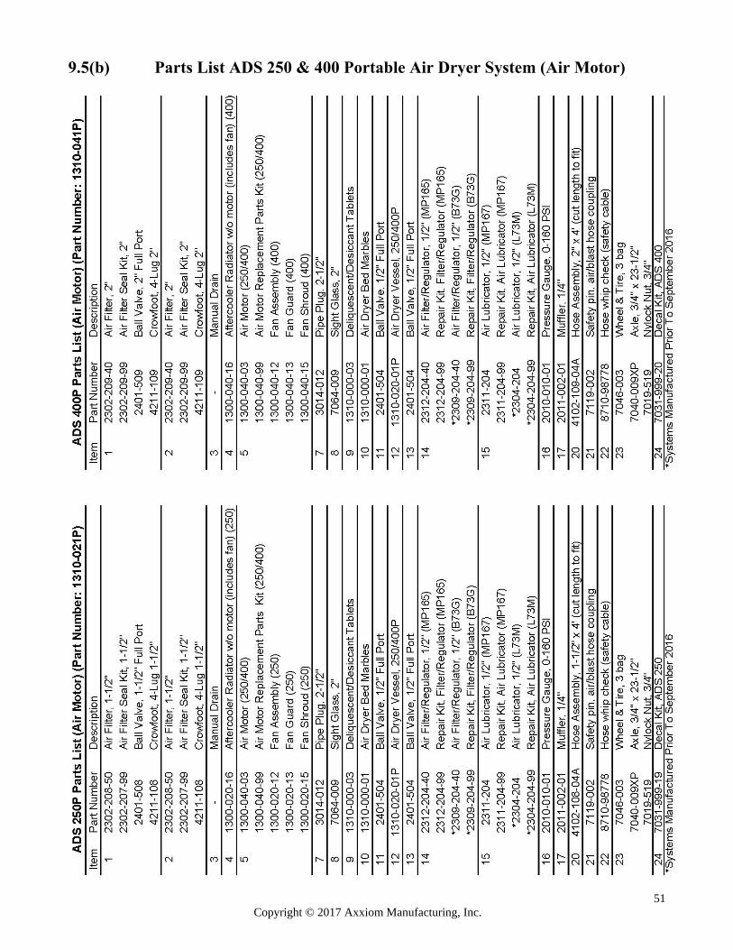
51 Copyright © 2017 Axxiom Manufacturing, Inc.
9.5(b) Parts List ADS 250 & 400 Portable Air Dryer System (Air Motor)
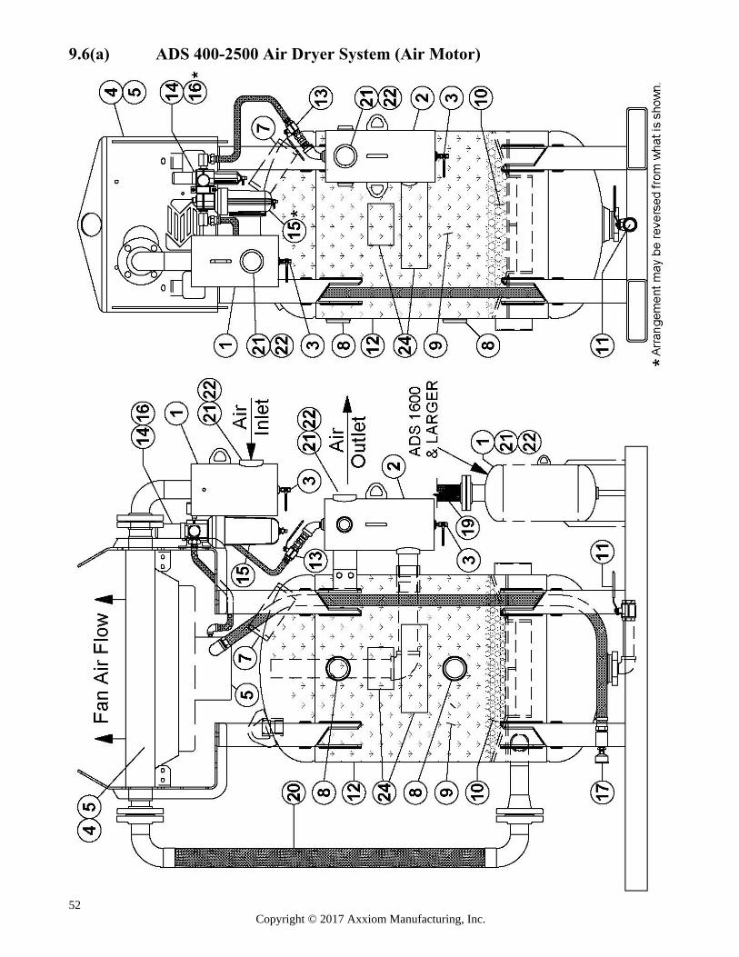
52 Copyright © 2017 Axxiom Manufacturing, Inc.
9.6(a) ADS 400-2500 Air Dryer System (Air Motor)
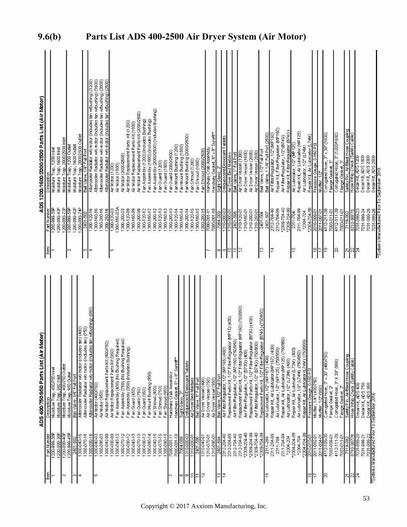
53 Copyright © 2017 Axxiom Manufacturing, Inc.
9.6(b) Parts List ADS 400-2500 Air Dryer System (Air Motor)
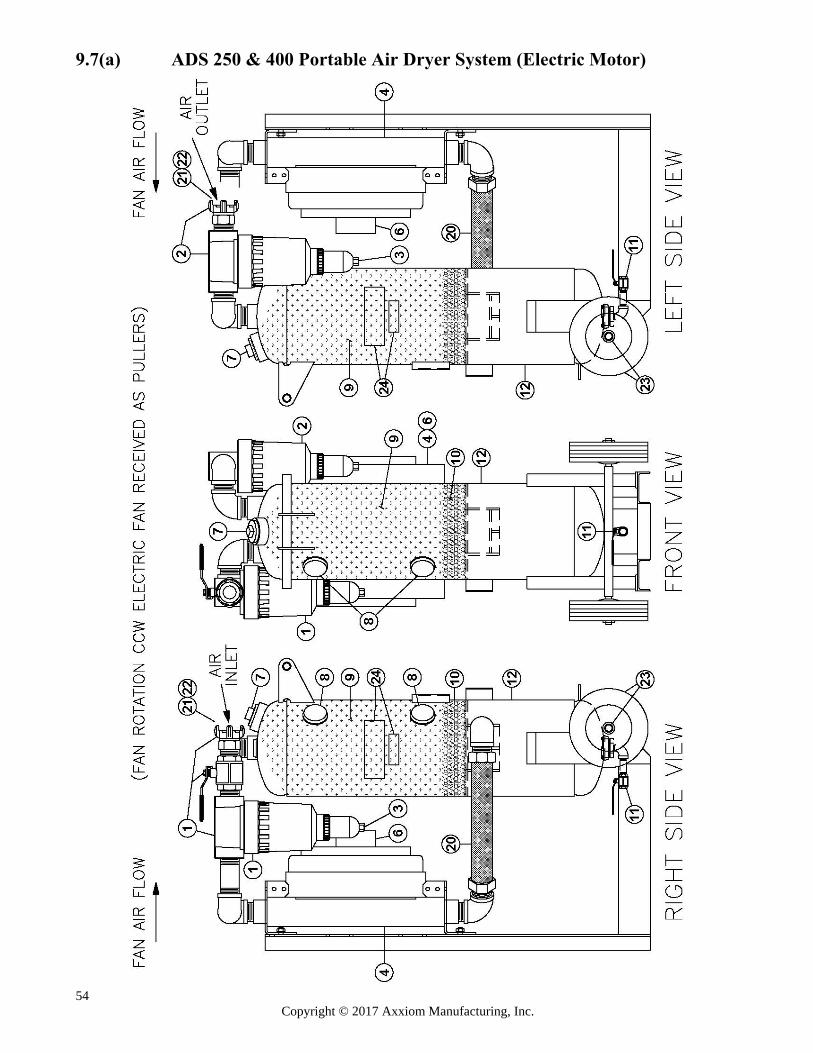
54 Copyright © 2017 Axxiom Manufacturing, Inc.
9.7(a) ADS 250 & 400 Portable Air Dryer System (Electric Motor)
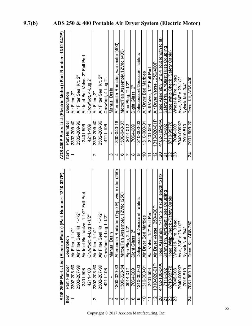
55 Copyright © 2017 Axxiom Manufacturing, Inc.
9.7(b) ADS 250 & 400 Portable Air Dryer System (Electric Motor)
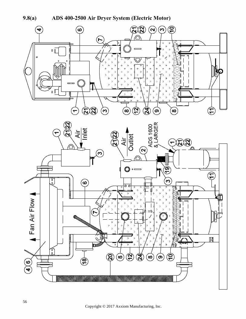
56 Copyright © 2017 Axxiom Manufacturing, Inc.
9.8(a) ADS 400-2500 Air Dryer System (Electric Motor)
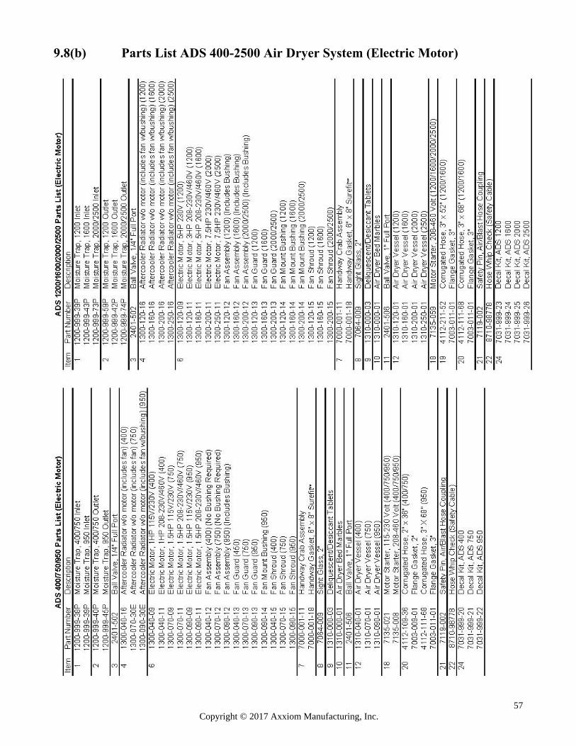
57 Copyright © 2017 Axxiom Manufacturing, Inc.
9.8(b) Parts List ADS 400-2500 Air Dryer System (Electric Motor)
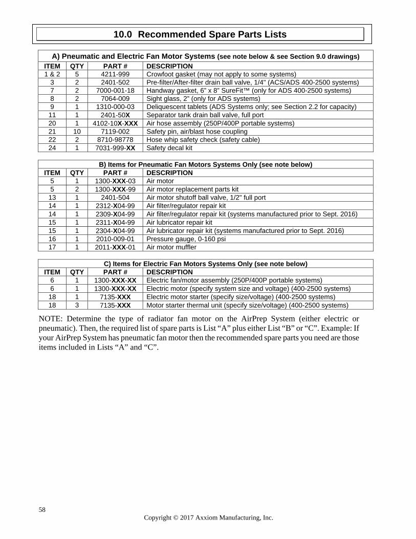
58 Copyright © 2017 Axxiom Manufacturing, Inc.
A) Pneumatic and Electric Fan Motor Systems (see note below & see Section 9.0 drawings) ITEM QTY PART # DESCRIPTION 1 & 2 5 4211-999 Crowfoot gasket (may not apply to some systems)
3 2 2401-502 Pre-filter/After-filter drain ball valve, 1/4" (ACS/ADS 400-2500 systems) 7 2 7000-001-18 Handway gasket, 6” x 8” SureFit™ (only for ADS 400-2500 systems) 8 2 7064-009 Sight glass, 2” (only for ADS systems) 9 1 1310-000-03 Deliquescent tablets (ADS Systems only; see Section 2.2 for capacity) 11 1 2401-50X Separator tank drain ball valve, full port 20 1 4102-10X-XXX Air hose assembly (250P/400P portable systems) 21 10 7119-002 Safety pin, air/blast hose coupling 22 2 8710-98778 Hose whip safety check (safety cable) 24 1 7031-999-XX Safety decal kit
B) Items for Pneumatic Fan Motors Systems Only (see note below)
ITEM QTY PART # DESCRIPTION 5 1 1300-XXX-03 Air motor 5 2 1300-XXX-99 Air motor replacement parts kit 13 1 2401-504 Air motor shutoff ball valve, 1/2" full port 14 1 2312-X04-99 Air filter/regulator repair kit 14 1 2309-X04-99 Air filter/regulator repair kit (systems manufactured prior to Sept. 2016) 15 1 2311-X04-99 Air lubricator repair kit 15 1 2304-X04-99 Air lubricator repair kit (systems manufactured prior to Sept. 2016) 16 1 2010-009-01 Pressure gauge, 0-160 psi 17 1 2011-XXX-01 Air motor muffler
C) Items for Electric Fan Motors Systems Only (see note below)
ITEM QTY PART # DESCRIPTION 6 1 1300-XXX-XX Electric fan/motor assembly (250P/400P portable systems) 6 1 1300-XXX-XX Electric motor (specify system size and voltage) (400-2500 systems) 18 1 7135-XXX Electric motor starter (specify size/voltage) (400-2500 systems) 18 3 7135-XXX Motor starter thermal unit (specify size/voltage) (400-2500 systems)
NOTE: Determine the type of radiator fan motor on the AirPrep System (either electric or pneumatic). Then, the required list of spare parts is List “A” plus either List “B” or “C”. Example: If your AirPrep System has pneumatic fan motor then the recommended spare parts you need are those items included in Lists “A” and “C”.
10.0 Recommended Spare Parts Lists
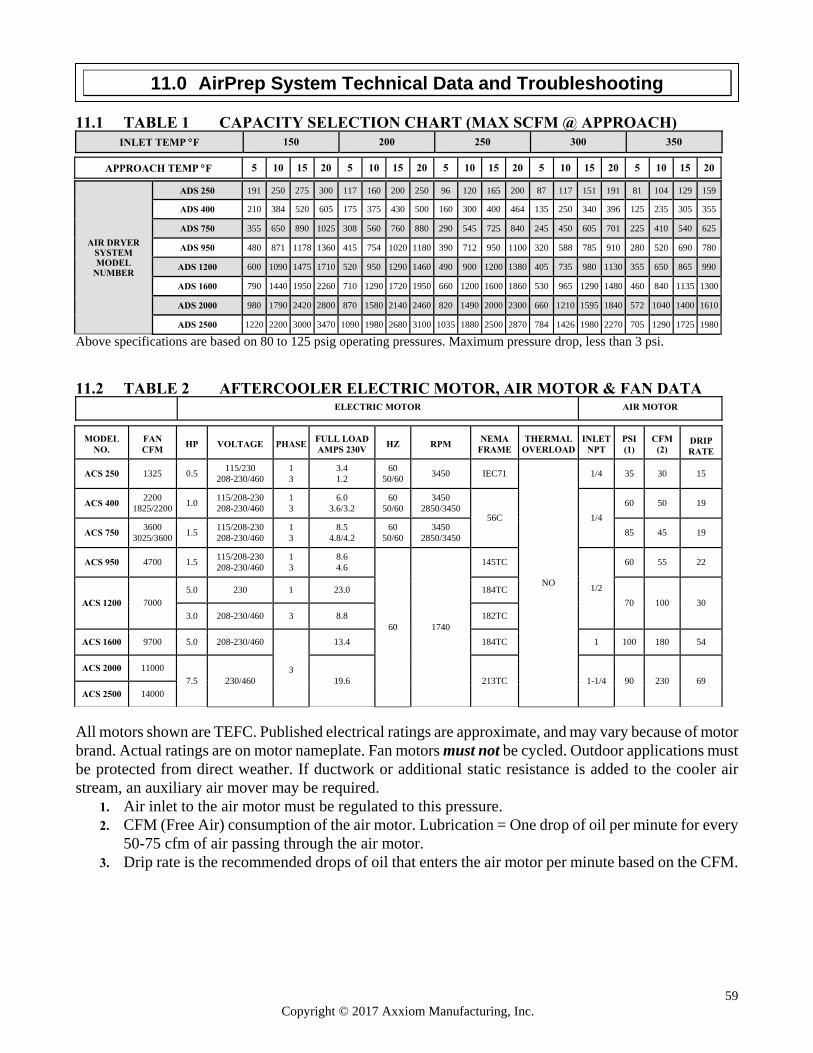
59 Copyright © 2017 Axxiom Manufacturing, Inc.
11.1 TABLE 1 CAPACITY SELECTION CHART (MAX SCFM @ APPROACH)
INLET TEMP F
150
200
250
300
350
Above specifications are based on 80 to 125 psig operating pressures. Maximum pressure drop, less than 3 psi.
11.2 TABLE 2 AFTERCOOLER ELECTRIC MOTOR, AIR MOTOR & FAN DATA
ELECTRIC MOTOR
AIR MOTOR
All motors shown are TEFC. Published electrical ratings are approximate, and may vary because of motor brand. Actual ratings are on motor nameplate. Fan motors must not be cycled. Outdoor applications must be protected from direct weather. If ductwork or additional static resistance is added to the cooler air stream, an auxiliary air mover may be required.
1. Air inlet to the air motor must be regulated to this pressure. 2. CFM (Free Air) consumption of the air motor. Lubrication = One drop of oil per minute for every
50-75 cfm of air passing through the air motor. 3. Drip rate is the recommended drops of oil that enters the air motor per minute based on the CFM.
APPROACH TEMP F
5
10
15
20
5
10
15
20
5
10
15
20
5
10
15
20
5
10
15
20
AIR DRYER
SYSTEM MODEL
NUMBER
ADS 250
191
250
275
300
117
160
200
250
96
120
165
200
87
117
151
191
81
104
129
159
ADS 400
210
384
520
605
175
375
430
500
160
300
400
464
135
250
340
396
125
235
305
355
ADS 750
355
650
890
1025
308
560
760
880
290
545
725
840
245
450
605
701
225
410
540
625
ADS 950
480
871
1178
1360
415
754
1020
1180
390
712
950
1100
320
588
785
910
280
520
690
780
ADS 1200
600
1090
1475
1710
520
950
1290
1460
490
900
1200
1380
405
735
980
1130
355
650
865
990
ADS 1600
790
1440
1950
2260
710
1290
1720
1950
660
1200
1600
1860
530
965
1290
1480
460
840
1135
1300
ADS 2000
980
1790
2420
2800
870
1580
2140
2460
820
1490
2000
2300
660
1210
1595
1840
572
1040
1400
1610
ADS 2500
1220
2200
3000
3470
1090
1980
2680
3100
1035
1880
2500
2870
784
1426
1980
2270
705
1290
1725
1980
MODEL
NO.
FAN CFM
HP
VOLTAGE
PHASE
FULL LOAD AMPS 230V
HZ
RPM
NEMA
FRAME
THERMAL
OVERLOAD
INLET
NPT
PSI (1)
CFM
(2)
DRIP RATE
ACS 250 1325 0.5 115/230
208-230/460 1 3
3.4 1.2
60 50/60
3450 IEC71
NO
1/4 35 30 15
ACS 400 2200
1825/2200 1.0
115/208-230 208-230/460
1 3
6.0 3.6/3.2
60 50/60
3450 2850/3450
56C 1/4
60 50 19
ACS 750 3600
3025/3600 1.5
115/208-230 208-230/460
1 3
8.5 4.8/4.2
60 50/60
3450 2850/3450
85 45 19
ACS 950 4700 1.5 115/208-230 208-230/460
1 3
8.6 4.6
60 1740
145TC
1/2
60 55 22
ACS 1200 7000
5.0 230 1 23.0 184TC
70 100 30
3.0 208-230/460 3 8.8 182TC
ACS 1600 9700 5.0 208-230/460
3
13.4 184TC 1 100 180 54
ACS 2000 11000
7.5 230/460 19.6 213TC 1-1/4 90 230 69
ACS 2500 14000
11.0 AirPrep System Technical Data and Troubleshooting
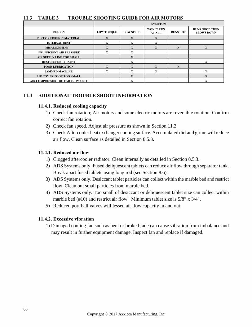
60 Copyright © 2017 Axxiom Manufacturing, Inc.
11.3 TABLE 3 TROUBLE SHOOTING GUIDE FOR AIR MOTORS
SYMPTOM
REASON
LOW TORQUE
LOW SPEED
WON'T RUN
AT ALL RUNS HOT
RUNS GOOD THEN
SLOWS DOWN
DIRT OR FOREIGN MATERIAL
X
X
X
INTERNAL RUST
X
X
X
MISALIGNMENT
X
X
X
X
X
INSUFFICIENT AIR PRESSURE
X
X
AIR SUPPLY LINE TOO SMALL
X
RESTRICTED EXHAUST
X
X
POOR LUBRICATION
X
X
X
X
JAMMED MACHINE
X
X
X
X
AIR COMPRESSOR TOO SMALL
X
X
AIR COMPRESSOR TOO FAR FROM UNIT
X
X
11.4 ADDITIONAL TROUBLE SHOOT INFORMATION
11.4.1. Reduced cooling capacity 1) Check fan rotation; Air motors and some electric motors are reversible rotation. Confirm
correct fan rotation. 2) Check fan speed. Adjust air pressure as shown in Section 11.2. 3) Check Aftercooler heat exchanger cooling surface. Accumulated dirt and grime will reduce
air flow. Clean surface as detailed in Section 8.5.3.
11.4.1. Reduced air flow 1) Clogged aftercooler radiator. Clean internally as detailed in Section 8.5.3. 2) ADS Systems only. Fused deliquescent tablets can reduce air flow through separator tank.
Break apart fused tablets using long rod (see Section 8.6). 3) ADS Systems only. Desiccant tablet particles can collect within the marble bed and restrict
flow. Clean out small particles from marble bed. 4) ADS Systems only. Too small of desiccant or deliquescent tablet size can collect within
marble bed (#10) and restrict air flow. Minimum tablet size is 5/8” x 3/4". 5) Reduced port ball valves will lessen air flow capacity in and out.
11.4.2. Excessive vibration
1) Damaged cooling fan such as bent or broke blade can cause vibration from imbalance and may result in further equipment damage. Inspect fan and replace if damaged.
61 Copyright © 2017 Axxiom Manufacturing, Inc.
12.1 Warranty The following sections are to be used as a guide in determining warranty policies and procedures for SCHMIDT® products. It is to be used in determining whether a warranty is justified and as a procedural guide in completing a SCHMIDT warranty claim.
12.2 Warranty Policy
1. All SCHMIDT products are guaranteed to be free of defects in material and workmanship at time of shipment. Axxiom Manufacturing, Inc. warrants its products against defects in material and workmanship under normal and proper use for a period of ninety (90) days from the date of delivery. Such warranty is extended only to the buyer who purchases the equipment directly from Axxiom Manufacturing, Inc. or its authorized distributors. This warranty does not include expendable parts such as, but not limited to, hoses, nozzles, and seals.
2. The obligation under this warranty is strictly limited to the replacement or repair, at Axxiom’s
option, of machines and does not include the cost of transportation, loss of operating time, or normal maintenance services. Axxiom Manufacturing, Inc. shall have no liability for labor, consequential damages, freight or special charges.
3. This warranty does not apply to failure occurring due to abuse, misuse, negligence, corrosion,
erosion, normal wear and tear, alterations or modifications made to the machine without express written consent of Axxiom Manufacturing, Inc.
4. Warranty requests must be submitted in writing within thirty (30) days after failure. 5. Written authorization to return merchandise under warranty must first be obtained from
Axxiom Manufacturing, Inc. In no case is merchandise to be returned to Axxiom for credit without authorization. At the time of authorization, Axxiom will issue a return authorization number that must be included on all packages and correspondence. Any material returned without prior authorization will remain the property of the sender and Axxiom will not be responsible for it.
6. All returns must be shipped prepaid freight. All returns may be exchanged for other equipment
or parts of equal dollar value. If goods are not exchanged, they are subject to a 20% restocking charge. Any cost incurred by Axxiom Manufacturing, Inc. to restore such goods to first class condition will be charged to the customer.
7. Axxiom Manufacturing, Inc. reserves the right to inspect and make the final decision on any
merchandise returned under warranty.
8. Axxiom Manufacturing, Inc. offers no warranty with respect to accessories, including but not limited to, engines, motors, batteries, tires and any other parts not manufactured by Axxiom Manufacturing, Inc., but which the original manufacturer warrants.
12.0 Warranty and Reference Information
62 Copyright © 2017 Axxiom Manufacturing, Inc.
9. Axxiom Manufacturing, Inc. reserves the right to make product changes or improvements without prior notice and without imposing any obligation upon itself to install the same on its products previously sold.
10. The above warranty conditions can only be altered by Axxiom Manufacturing, Inc. Axxiom
must confirm alterations in writing for each specific transaction.
11. Axxiom Manufacturing, Inc. reserves the right to establish specific warranty terms for used or demo machines on an individual transaction basis. Invoices covering such merchandise will clearly state the provisions of the applicable warranty for each specific transaction.
12. USE OF NON-ORIGINAL SCHMIDT® FACTORY REPLACEMENT PARTS ON ANY
SCHMIDT EQUIPMENT VOIDS ALL WARRANTIES.
13. AXXIOM MANUFACTURING, INC. DOES NOT AUTHORIZE ANY PERSON, REPRESENTATIVE OR SERVICE OR SALES ORGANIZATION TO MAKE ANY OTHER WARRANTY OR TO ASSUME ON BEHALF OF AXXIOM MANUFACTURING, INC. ANY LIABILITY IN CONNECTION WITH THE SALE OF OUR PRODUCTS OTHER THAN THOSE CONTAINED HEREIN.
14. UNDER NO CIRCUMSTANCES SHALL AXXIOM MANUFACTURING, INC. BE
LIABLE TO CUSTOMER OR ANY OTHER PERSON FOR ANY DIRECT, INCIDENTAL, OR CONSEQUENTIAL DAMAGES RESULTING FROM THE USE OF THE PRODUCT OR ARISING OUT OF ANY BREACH OF ANY WARRANTY OR FOR ANY SPECIAL OR CONSEQUENTIAL DAMAGES OF ANY CHARACTER, INCLUDING WITHOUT LIMITATIONS, DAMAGES FOR ANY LOSS OF GOODWILL, WORK STOPPAGE, OR ANY AND ALL OTHER COMMERCIAL DAMAGES OR LOSSES.
15. AXXIOM MANUFACTURING, INC. MAKES NO OTHER WARRANTIES, EXPRESSED
OR IMPLIED, INCLUDING, BUT NOT LIMITED TO, THE IMPLIED WARRANTIES OF MERCHANTABILITY AND FITNESS FOR A PARTICULAR PURPOSE WITH RESPECT TO THE SCHMIDT PRODUCTS SOLD PURSUANT THERETO.
12.3 Trademarks, Patents, and Proprietary Statements
Schmidt®, the Schmidt stylized “S” logo, Thompson®, Microvalve®, MV2®, Tera Valve®, and Combovalve® are registered trademarks owned by Axxiom Manufacturing, Inc. Use of Schmidt, the Schmidt stylized “S” logo, Thompson, Microvalve, MV2, Tera Valve, and Combovalve trademarks without the written consent of Axxiom Manufacturing is strictly prohibited. Products manufactured and marketed by Axxiom Manufacturing, Inc. are protected by patents issued or pending in the United States and other countries. The text, diagrams, and drawings contained in this manual are proprietary information intended solely for instruction in the operation of the specified equipment. Use of any text, diagrams, or drawings contained in this manual for any reason other than its intended purpose without the written consent of Axxiom Manufacturing, Inc. is strictly prohibited.
63 Copyright © 2017 Axxiom Manufacturing, Inc.
12.4 Safety Information Sources
Axxiom Manufacturing, Inc This equipment and all Schmidt® equipment are manufactured exclusively by Axxiom Manufacturing, Inc. If any operational or safety related questions arise relating to this equipment contact Axxiom Manufacturing, Inc. Phone: 1-800-231-2035 Website: www.axxiommfg.com Axxiom Manufacturing, Inc. 11927 South Highway 6 Fresno, Texas 77459 Occupational Safety and Health Administration (OSHA) establishes and enforces regulations regarding safety practices in the workplace including the abrasive blasting industry. Any questions, reporting of work related injuries, or reporting of unsafe work practices can be made to the following contact information. Answers to most any safety related questions can be found at the OSHA website shown below. Phone: 1-800-321-6742 Website: www.osha.gov
U.S. Department of Labor
Occupational Safety and Health Administration 200 Constitution Avenue Washington D.C. 20210
National Institute of Occupational Safety and Health (NIOSH) is a federal agency responsible for conducting research and recommendations for the prevention of work related injuries and sickness. Phone: 1-800-356-4674 Website: www.cdc.gov/niosh National Institute of Occupational Safety and Health Hubert H. Humphrey Bldg. 200 Independence Avenue, SW Room 715H Washington, DC 20201 American National Standards Institute (ANSI) coordinates the development and use of voluntary consensus standards including safety standards. Phone: 1-202-293-8020 Website: www.ansi.org American National Standards Institute 1819 L Street, NW 6th Floor Washington, DC 20036
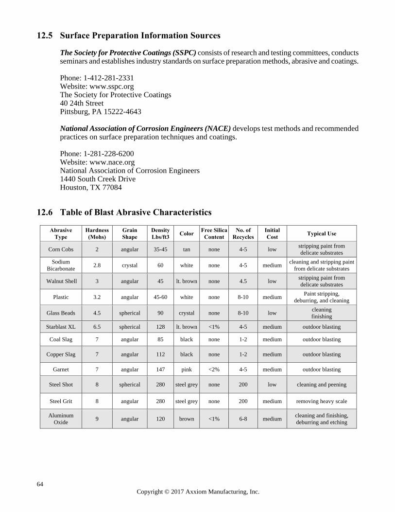
64 Copyright © 2017 Axxiom Manufacturing, Inc.
12.5 Surface Preparation Information Sources
The Society for Protective Coatings (SSPC) consists of research and testing committees, conducts seminars and establishes industry standards on surface preparation methods, abrasive and coatings. Phone: 1-412-281-2331 Website: www.sspc.org The Society for Protective Coatings 40 24th Street Pittsburg, PA 15222-4643 National Association of Corrosion Engineers (NACE) develops test methods and recommended practices on surface preparation techniques and coatings. Phone: 1-281-228-6200 Website: www.nace.org National Association of Corrosion Engineers 1440 South Creek Drive Houston, TX 77084
12.6 Table of Blast Abrasive Characteristics
Abrasive Type
Hardness (Mohs)
Grain Shape
Density Lbs/ft3
Color Free Silica
Content No. of
Recycles Initial Cost
Typical Use
Corn Cobs 2 angular 35-45 tan none 4-5 low stripping paint from delicate substrates
Sodium Bicarbonate
2.8 crystal 60 white none 4-5 medium cleaning and stripping paint
from delicate substrates
Walnut Shell 3 angular 45 lt. brown none 4.5 low stripping paint from delicate substrates
Plastic 3.2 angular 45-60 white none 8-10 medium Paint stripping,
deburring, and cleaning
Glass Beads 4.5 spherical 90 crystal none 8-10 low cleaning finishing
Starblast XL 6.5 spherical 128 lt. brown <1% 4-5 medium outdoor blasting
Coal Slag 7 angular 85 black none 1-2 medium outdoor blasting
Copper Slag 7 angular 112 black none 1-2 medium outdoor blasting
Garnet 7 angular 147 pink <2% 4-5 medium outdoor blasting
Steel Shot 8 spherical 280 steel grey none 200 low cleaning and peening
Steel Grit 8 angular 280 steel grey none 200 medium removing heavy scale
Aluminum Oxide
9 angular 120 brown <1% 6-8 medium cleaning and finishing, deburring and etching

65 Copyright © 2017 Axxiom Manufacturing, Inc.
NOTES
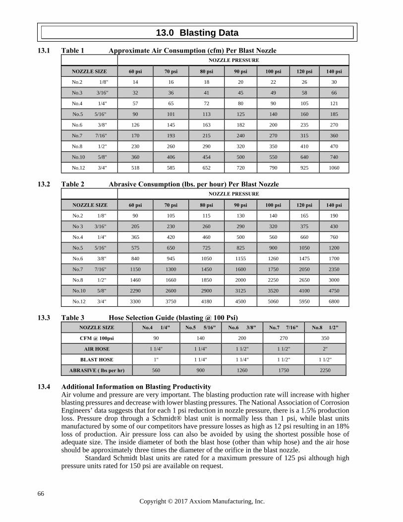
66 Copyright © 2017 Axxiom Manufacturing, Inc.
13.1 Table 1 Approximate Air Consumption (cfm) Per Blast Nozzle
NOZZLE PRESSURE
NOZZLE SIZE
60 psi
70 psi
80 psi
90 psi
100 psi
120 psi
140 psi
No.2 1/8"
14
16
18
20
22
26
30
No.3 3/16"
32
36
41
45
49
58
66
No.4 1/4"
57
65
72
80
90
105
121
No.5 5/16"
90
101
113
125
140
160
185
No.6 3/8"
126
145
163
182
200
235
270
No.7 7/16"
170
193
215
240
270
315
360
No.8 1/2"
230
260
290
320
350
410
470
No.10 5/8"
360
406
454
500
550
640
740
No.12 3/4"
518
585
652
720
790
925
1060
13.2 Table 2 Abrasive Consumption (lbs. per hour) Per Blast Nozzle
NOZZLE PRESSURE
NOZZLE SIZE
60 psi
70 psi
80 psi
90 psi
100 psi
120 psi
140 psi
No.2 1/8"
90
105
115
130
140
165
190
No 3 3/16"
205
230
260
290
320
375
430
No.4 1/4"
365
420
460
500
560
660
760
No.5 5/16"
575
650
725
825
900
1050
1200
No.6 3/8"
840
945
1050
1155
1260
1475
1700
No.7 7/16"
1150
1300
1450
1600
1750
2050
2350
No.8 1/2"
1460
1660
1850
2000
2250
2650
3000
No.10 5/8"
2290
2600
2900
3125
3520
4100
4750
No.12 3/4"
3300
3750
4180
4500
5060
5950
6800
13.3 Table 3 Hose Selection Guide (blasting @ 100 Psi)
NOZZLE SIZE
No.4 1/4" No.5 5/16"
No.6 3/8"
No.7 7/16"
No.8 1/2"
CFM @ 100psi
90
140
200
270
350
AIR HOSE
1 1/4"
1 1/4"
1 1/2"
1 1/2"
2"
BLAST HOSE
1"
1 1/4"
1 1/4"
1 1/2"
1 1/2"
ABRASIVE ( lbs per hr)
560
900
1260
1750
2250
13.4 Additional Information on Blasting Productivity Air volume and pressure are very important. The blasting production rate will increase with higher blasting pressures and decrease with lower blasting pressures. The National Association of Corrosion Engineers’ data suggests that for each 1 psi reduction in nozzle pressure, there is a 1.5% production loss. Pressure drop through a Schmidt® blast unit is normally less than 1 psi, while blast units manufactured by some of our competitors have pressure losses as high as 12 psi resulting in an 18% loss of production. Air pressure loss can also be avoided by using the shortest possible hose of adequate size. The inside diameter of both the blast hose (other than whip hose) and the air hose should be approximately three times the diameter of the orifice in the blast nozzle.
Standard Schmidt blast units are rated for a maximum pressure of 125 psi although high pressure units rated for 150 psi are available on request.
13.0 Blasting Data