act request doc 85256 - dlr · ecss european cooperation for space standardization ... european...
TRANSCRIPT
This document remains our property and should not be copied without our written allowance. Nor is it permitted to show or give this document to a third person. Contravention will be prosecuted with the support of existing law.
Rexus Manual
Document ID:
Version: Issue Date: Document Type: Valid from:
4.5 5 December 2007 Spec
Issued by:
........ ................................................................
Olle Persson, A. Stamminger, H. Hellmann
Approved by:
........................................................................
Olle Persson
Distribution:
Published 2007-12-05
Change Record
Version Date Changed chapters Remarks
Draft 070207 Text TBD is in italic and underwritten
070814
070827
070907
4 071129 Hellmann, Stamminger
4.3 071130 O.Persson, A. Stamminger
4.4 071205 O. Persson
4,5 071205 O. Persson
Abstract: -
Keywords: -
Table of Contents
1 INTRODUCTION........................................................................................................ 6
1.1 Definitions........................................................................................................... 7
1.2 Abbreviations ...................................................................................................... 8
1.3 References........................................................................................................... 9
2 REXUS PROJECT OVERVIEW AND MILESTONES ........................................... 10
2.1 Project Organisation.......................................................................................... 10
2.2 Project Planning ................................................................................................ 10
2.2.1 Project Phases [Ref [1]]: ..................................................................... 10
2.2.2 General REXUS Timetable ................................................................ 11
2.3 REXUS Flight Ticket........................................................................................ 11
2.4 Additional services............................................................................................ 12
2.5 Student Experiment Documentation ................................................................. 12
2.6 Mission Flight Handbook (MFH) ..................................................................... 12
3 REXUS SYSTEM ...................................................................................................... 13
3.1 REXUS vehicle................................................................................................. 13
3.1.1 Service Module ................................................................................... 13
3.1.2 Rate Control........................................................................................ 14
3.1.3 Recovery Module................................................................................ 14
3.1.4 Homing aid ......................................................................................... 14
3.1.5 TV-Channel ........................................................................................ 14
3.2 Body Frame Coordinate System (BF)............................................................... 14
3.3 Performance, Flight Sequence .......................................................................... 15
3.3.1 Nominal trajectory .............................................................................. 15
3.3.2 Graphs of a Nominal Trajectory ......................................................... 16
3.4 The REXUS thermal environment.................................................................... 19
3.4.1 Pre-launch Phase................................................................................. 19
3.4.2 Count Down Phase ............................................................................. 19
3.4.3 Flight Phase ........................................................................................ 19
3.4.4 Post-flight phase ................................................................................. 19
4 MECHANICAL DESIGN OF EXPERIMENTS ....................................................... 20
4.1 Baseline Module design.................................................................................... 21
4.2 REXUS modules thermal requirements............................................................ 21
4.2.1 Heating of the outer structure ............................................................. 21
4.2.2 Temperature at the feed-through cable ............................................... 22
4.2.3 Heat radiation in the module interfaces .............................................. 22
4.2.4 Convection between connecting modules .......................................... 22
4.3 Hatches.............................................................................................................. 22
4.4 Exhaust openings .............................................................................................. 22
4.5 Dimensioning loads during launch, flight and recovery................................... 23
4.5.1 Acceleration ........................................................................................ 23
4.5.2 Re-entry Loads.................................................................................... 23
4.5.3 Landing Velocity ................................................................................ 23
4.6 Mechanical Retroaction Forces from Modules on the Payload ........................ 23
4.6.1 Vehicle Characteristics ....................................................................... 23
4.6.2 Movements ......................................................................................... 23
4.6.3 Vibrations ........................................................................................... 23
4.7 Mass balance and mass properties ................................................................... 24
5 ELECTRICAL DESIGN OF EXPERIMENTS ......................................................... 25
5.1 General .............................................................................................................. 25
5.2 Telemetry System ............................................................................................. 25
5.3 Telecommand System....................................................................................... 25
5.4 Interface Connector Description to REXUS Service Module .......................... 26
5.4.1 Objectives ........................................................................................... 26
5.4.2 Interface Description Onboard ........................................................... 26
5.4.3 Standard Experiment Interface for REXUS Payloads ........................ 28
5.4.4 Interface Description on Ground ........................................................ 29
5.5 Additional Batteries .......................................................................................... 29
5.6 Umbilicals ......................................................................................................... 30
5.6.1 Orientation .......................................................................................... 30
5.6.2 Electrical umbilical provided by experimenters ................................. 30
5.6.3 High Power Connections .................................................................... 30
5.6.4 Ground Support Equipment-Umbilical interface................................ 30
5.7 Electro Magnetic Compatibility........................................................................ 30
6 EXPERIMENT REVIEWS AND TESTS ................................................................. 31
6.1 Kick-Off Meeting.............................................................................................. 31
6.2 Preliminary Design Review, PDR .................................................................... 31
6.3 Critical Design Review, CDR........................................................................... 31
6.4 Progress Report / Mid Term Report.................................................................. 31
6.5 Vacuum test ...................................................................................................... 31
6.6 Thermal test ...................................................................................................... 32
6.7 Vibration test..................................................................................................... 33
6.8 Experiment Acceptance Review, EAR ............................................................. 34
6.8.1 Electrical Interface Test ...................................................................... 34
6.8.2 Flight Simulation Test ........................................................................ 34
6.9 PAYLOAD ASSEMBLY AND INTEGRATION TESTS............................... 35
6.9.1 Experiment Status by Delivery........................................................... 35
6.9.2 Experiment Incoming Inspection........................................................ 35
6.9.3 Payload Assembly .............................................................................. 35
6.9.4 Payload System Tests ......................................................................... 35
6.9.5 Mechanical Interface Test................................................................... 36
6.9.6 Electrical Interface Test ...................................................................... 36
6.9.7 Module Checkout................................................................................ 36
6.9.8 Mass Properties and Balancing........................................................... 36
6.9.9 Spin test .............................................................................................. 36
6.9.10 Bend Test ............................................................................................ 36
6.9.11 System Electrical Test 1 and EMI-check............................................ 36
6.9.12 Payload vibration Test ........................................................................ 37
6.9.13 Flight Simulation Test ........................................................................ 37
6.10 Flight Acceptance Review ................................................................................ 37
6.11 Flight Readiness Review................................................................................... 37
7 LAUNCH CAMPAIGN ............................................................................................. 38
7.1 Description of Esrange Space Center ............................................................... 39
7.2 Assembly of rockets and payloads.................................................................... 39
7.2.1 Assembly of rockets ........................................................................... 39
7.2.2 Assembly and checkout of payloads................................................... 39
7.3 Countdown and Launch .................................................................................... 39
7.4 Recovery ........................................................................................................... 40
8 EXPERIMENT QUALITY ASSURANCE ............................................................... 41
8.1 Materials ........................................................................................................... 41
8.2 Components ...................................................................................................... 41
8.3 Additional quality topics................................................................................... 41
8.3.1 Procured products and audits.............................................................. 41
8.3.2 Manufacturing control and inspection ................................................ 41
8.3.3 Re-used Item....................................................................................... 42
8.3.4 Availability and Maintainability......................................................... 42
8.3.5 Handling, storage and packing ........................................................... 42
8.4 Personnel Safety................................................................................................ 42
8.5 Safety at Esrange Space Center ........................................................................ 42
9 COORDINATE SYSTEM DEFINITION.................................................................. 43
9.1 Earth Centered Inertial System (ECI) ............................................................... 43
9.2 Earth Centered, Earth Fixed (ECEF) ................................................................ 45
9.3 Local Tangential Coordinate System (LTC)..................................................... 47
9.4 Vehicle Carried Vertical Frame (VCVF).......................................................... 48
Page 6
Rexus User Manual
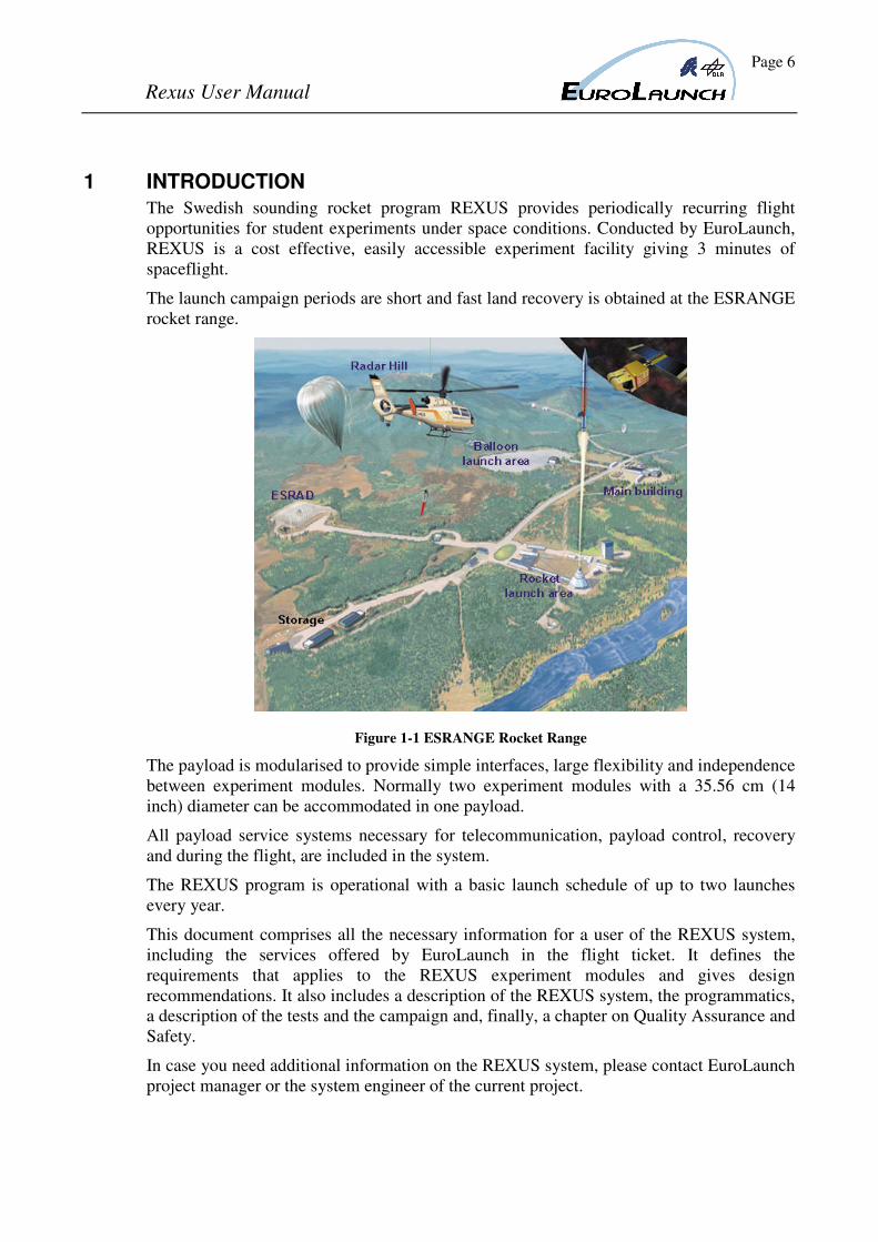
1 INTRODUCTION
The Swedish sounding rocket program REXUS provides periodically recurring flight
opportunities for student experiments under space conditions. Conducted by EuroLaunch,
REXUS is a cost effective, easily accessible experiment facility giving 3 minutes of
spaceflight.
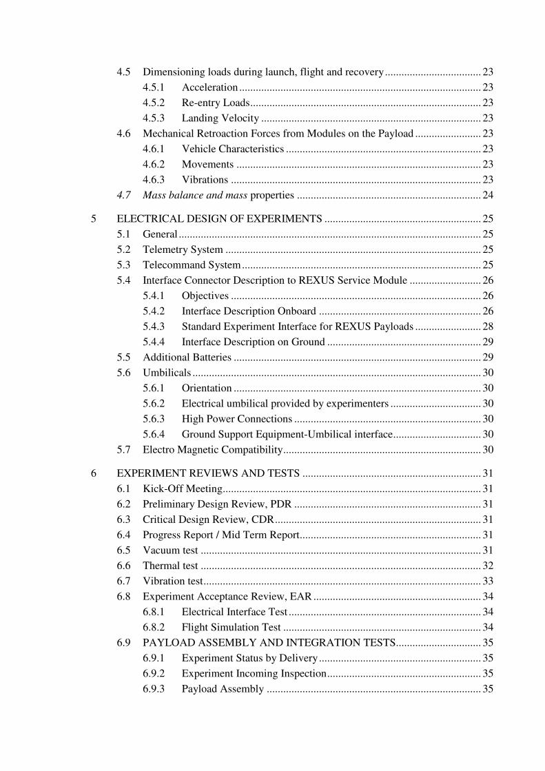
The launch campaign periods are short and fast land recovery is obtained at the ESRANGE
rocket range.
Figure 1-1 ESRANGE Rocket Range
The payload is modularised to provide simple interfaces, large flexibility and independence
between experiment modules. Normally two experiment modules with a 35.56 cm (14
inch) diameter can be accommodated in one payload.
All payload service systems necessary for telecommunication, payload control, recovery
and during the flight, are included in the system.
The REXUS program is operational with a basic launch schedule of up to two launches
every year.
This document comprises all the necessary information for a user of the REXUS system,
including the services offered by EuroLaunch in the flight ticket. It defines the
requirements that applies to the REXUS experiment modules and gives design
recommendations. It also includes a description of the REXUS system, the programmatics,
a description of the tests and the campaign and, finally, a chapter on Quality Assurance and
Safety.
In case you need additional information on the REXUS system, please contact EuroLaunch
project manager or the system engineer of the current project.
Page 7
Rexus User Manual
1.1 Definitions
The REXUS system consists of the following components according to Eurolaunch
definition.
REXUS The complete integrated vehicle to perform the flight.
Ground Equipment REXUS supporting systems on ground.
Esrange Facilities Equipment used to monitor and control the flight, and
telemetry receiving equipment.
Ground Support Equipment Equipment used to control and communicate with various
modules during test and count down.
Rocket Motors The parts of REXUS giving the accelerating force.
Payload Experiment modules and all subsystems.
Subsystems All systems required for flight control, recovery and
telemetry.
Experiment Modules Experiment equipment and the outer structure.
Page 8
Rexus User Manual
1.2 Abbreviations AIT Assembly, Integration and Test
APID Application Identifier
BF Body Frame Coordinate System
DLR Deutsches Zentrum für Luft- und Raufahrt
ECSS European Cooperation for Space Standardization
EGSE Ground Service Module control box
EMC Electro-Magnetic Compatibility
EMI Electro-Magnetic Interference
ESRANGE European Sounding Rocket Launching Range
FAR Flight Acceptance Review
FST Flight Simulation Test
FRR Flight Readiness Review
GSE Ground Support Equipment
HCD Hot Count Down
HK House Keeping
H/W Hardware
ICD Interface control document
I/F Interface
IH Igniter Housing
MFH Mission Flight Handbook
MTR Mid Time Review
NCR Non Conformance Report
REXUS Rocket EXperiment for University Students
RF Radio Frequency
RXSM REXUS Service Module
PCM Pulse Code Modulation
PI Principal Investigator
PST Payload System Test
RNRZ Randomized NRZ (a signalling modulation)
RXSM Rexus Service Module
SED Student Experiment Description
SSC Swedish Space Corporation
DLR Moraba DLR Mobile Raketenbasis
S/W Software
TC Telecommand
TCU Telemetry Central Unit
TM Telemetry
Page 9
Rexus User Manual
1.3 References
[1] European Cooperation for Space Standardization ECSS: Space Project
Management (ECSS-M-30A, 1996)
[2] Montenbruck, Oliver / Gill, Eberhard: Satellite Orbits (Springer Verlag, 2000)
[3] SSC Esrange: EU A00-E538 Esrange Safety (Esrange, www.ssc.se/esrange)
[4] SSC Esrange: User’s Handbook (Esrange, http://www.ssc.se/esrange)
[5] Vallado, David A.: Fundamentals of Astrodynamics and Applications (McGraw-
Hill Companies, Inc, 1997)
Page 10
Rexus User Manual
2 REXUS PROJECT OVERVIEW AND MILESTONES
2.1 Project Organisation
The technical support in the integration and testing phase, as well as the campaign
management and operations is provided by EuroLaunch. EuroLaunch was founded in
2003 and is a joint venture of Esrange (Swedish Space Cooperation SSC) and the Mobile
Rocket Base MORABA (German Aerospace Center DLR). The DLR service part
concerning integration, testing and student support is provided by the Institute of Space
Systems RY (DLR) in Bremen. When in this document EuroLaunch is mentioned this
means that all three institutions (Esrange, MORABA and RY) may be involved.
The REXUS rockets are launched at the European Sounding Rocket Launching Range
Esrange of SSC, near Kiruna in North-Sweden.
The scientific evaluation of the experiment proposals and the financial support of the
students are in the responsibility of the German Space Agency (DLR) and the Swedish
National Space Board (SNSB) through cooperation with the European Space Agency
(ESA).
At EuroLaunch the following key-positions will be assigned for every flight project:
- Project manager
- System manager
- Mechanical design responsible
- Electrical design responsible
- Telemetry (TM) and Telecommand (TC) systems responsible
- EGSE and software responsible
Additional positions will be assigned if necessary.
The major part of the communication between EuroLaunch and the experimenter shall pass
through the Project Managers.
2.2 Project Planning
The detailed project planning and time schedule will be released by EuroLaunch for each
flight at the first workshop.
A general progress plan for REXUS flight projects is listed below. Detailed description of
reviews and tests are given in chapter 6.
2.2.1 Project Phases [Ref [1]]:
Phase A: Feasibility Phase, ends with Form B and the presentation at the workshop
Phase B: Preliminary Design study phase, ends during the student training week with the
Preliminary Design Review (PDR)
Phase C: Detailed Definition Phase, ends with the Critical Design Review (CDR)
Page 11
Rexus User Manual
Phase D: Production and Qualification Phase, ends with the Experiment Acceptance
Review (EAR). The phases C and D are generally inseparable, owing to the
integrated nature of the activities.
Phase E: Launch and operation (campaign)
Phase F. Post flight analysis and final report
2.2.2 General REXUS Timetable
T-18 m Call for Experiment Proposals
T-16 m Experiment Submission Deadline
T-15 m Preliminary experiment selection
T-14 m Workshop in ESTEC (ESA) / Bonn (DLR); experiment presentation
T-13.5 m Final experiment selection
T-12 m Student Training Week at Esrange or Oberpfaffenhofen, Preliminary Design
Review (PDR)
T-9 m Critical Design Review (CDR), Start of phase D
T-6 m Mid Term Report (MTR)
T-3 m Delivery of Experiments to Esrange (ESA) / Bremen (DLR), EAR
T Campaign at Esrange
T+1 m Distribution of the REXUS post flight Report
T+3 m Submission of Student Experiment Reports
T+4 m Submission of Final Report
2.3 REXUS Flight Ticket
In the REXUS “flight ticket”, which is offered to the international student community, the
following services are included:
- General management and planning of the REXUS project
- Provision of launch vehicle and subsystems necessary for a spaceflight mission of
2-3 minutes with recovery. Lift-off signals are provided.
- Integration of participating modules into the flight configured payload and testing
of payload (TM, TC, flight simulation test, dynamic balancing, vibration tests and
determination of physical properties).
- Transport of modules from the integration facility to Esrange.
- Payload assembly and testing at the range during 5 days (nominally).
- Provision of laboratory facilities at the range.
- Launch and recovery.
- Data acquisition with provisions of real time, quick-look and replay data from
modules and payload subsystems (e.g. g-levels).
Page 12
Rexus User Manual
- Disassembly of recovered payload and return of modules for retrieval of processed
samples.
- Post flight report.
2.4 Additional services
The following services are available on request:
- Supply of outer structure.
- REXUS TM simulators can be available on request. The electrical input interface to
the simulator is the same as in flight configuration.
2.5 Student Experiment Documentation
Each student team will document their experiment setup, the experiment components,
interfaces, technical data and the flight requirements in the Student Experiment
Documentation (SED). This SED will be a living document during the project. At the end
of different project phases should have a certain status and it will be used as a required
documentation for PDR, CDR and MTR. The due date for the final version of this
document is before launch.
Once selected every experiment team will receive a SED blank book.
After the delivery of the experiment hardware there will be several tests. These tests are
performed in accordance with an established test plan and test procedure. The results are
documented in test reports and presented during the Experiment Acceptance Review.
Non-conformances shall be recorded in a Non-Conformance Report (NCR).
The test procedure shall contain:
- Scope of the test, referring to requirement in specification to be verified
- Test conditions
- Test equipment and set-up
- Step-by-step procedures
- Recording of data
- Success Criteria
All test report, action item lists and NCRs shall be attached to the SED.
2.6 Mission Flight Handbook (MFH)
The mission objectives, the vehicle design and operational constraints will be documented
during the project phase in the Mission Flight Handbook (MFH). All important
information of the MFH, the nominal trajectory and updated vehicle parameters will be
frozen in the Campaign Handbook at begin of the campaign. A Post Flight Report with
the flight events and trajectory data will be distributed as soon as possible after launch. All
three documents will be provided by EuroLaunch.
Page 13
Rexus User Manual
3 REXUS SYSTEM
3.1 REXUS vehicle
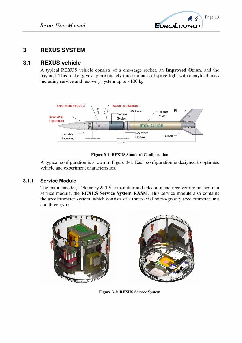
A typical REXUS vehicle consists of a one-stage rocket, an Improved Orion, and the
payload. This rocket gives approximately three minutes of spaceflight with a payload mass
including service and recovery system up to ~100 kg.
Figure 3-1: REXUS Standard Configuration
A typical configuration is shown in Figure 3-1. Each configuration is designed to optimise
vehicle and experiment characteristics.
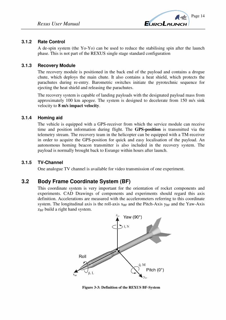
3.1.1 Service Module
The main encoder, Telemetry & TV transmitter and telecommand receiver are housed in a
service module, the REXUS Service System RXSM. This service module also contains
the accelerometer system, which consists of a three-axial micro-gravity accelerometer unit
and three gyros.
Figure 3-2: REXUS Service System
Page 14
Rexus User Manual
3.1.2 Rate Control
A de-spin system (the Yo-Yo) can be used to reduce the stabilising spin after the launch
phase. This is not part of the REXUS single stage standard configuration
3.1.3 Recovery Module
The recovery module is positioned in the back end of the payload and contains a drogue
chute, which deploys the main chute. It also contains a heat shield, which protects the
parachutes during re-entry. Barometric switches initiate the pyrotechnic sequence for
ejecting the heat shield and releasing the parachutes.
The recovery system is capable of landing payloads with the designated payload mass from
approximately 100 km apogee. The system is designed to decelerate from 150 m/s sink
velocity to 8 m/s impact velocity.
3.1.4 Homing aid
The vehicle is equipped with a GPS-receiver from which the service module can receive
time and position information during flight. The GPS-position is transmitted via the
telemetry stream. The recovery team in the helicopter can be equipped with a TM-receiver
in order to acquire the GPS-position for quick and easy localisation of the payload. An
autonomous homing beacon transmitter is also included in the recovery system. The
payload is normally brought back to Esrange within hours after launch.
3.1.5 TV-Channel
One analogue TV channel is available for video transmission of one experiment.
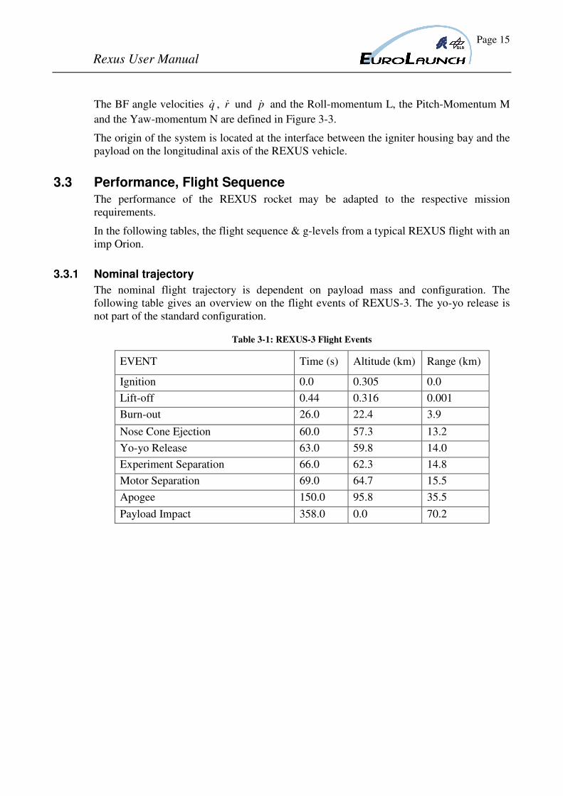
3.2 Body Frame Coordinate System (BF)
This coordinate system is very important for the orientation of rocket components and
experiments. CAD Drawings of components and experiments should regard this axis
definition. Accelerations are measured with the accelerometers referring to this coordinate
system. The longitudinal axis is the roll-axis xBF and the Pitch-Axis yBF and the Yaw-Axis
zBF build a right hand system.
Figure 3-3: Definition of the REXUS BF-System
Page 15
Rexus User Manual
The BF angle velocities q& , r& und p& and the Roll-momentum L, the Pitch-Momentum M
and the Yaw-momentum N are defined in Figure 3-3.
The origin of the system is located at the interface between the igniter housing bay and the
payload on the longitudinal axis of the REXUS vehicle.
3.3 Performance, Flight Sequence
The performance of the REXUS rocket may be adapted to the respective mission
requirements.
In the following tables, the flight sequence & g-levels from a typical REXUS flight with an
imp Orion.
3.3.1 Nominal trajectory
The nominal flight trajectory is dependent on payload mass and configuration. The
following table gives an overview on the flight events of REXUS-3. The yo-yo release is
not part of the standard configuration.
Table 3-1: REXUS-3 Flight Events
EVENT Time (s) Altitude (km) Range (km)
Ignition 0.0 0.305 0.0
Lift-off 0.44 0.316 0.001
Burn-out 26.0 22.4 3.9
Nose Cone Ejection 60.0 57.3 13.2
Yo-yo Release 63.0 59.8 14.0
Experiment Separation 66.0 62.3 14.8
Motor Separation 69.0 64.7 15.5
Apogee 150.0 95.8 35.5
Payload Impact 358.0 0.0 70.2
Page 16
Rexus User Manual
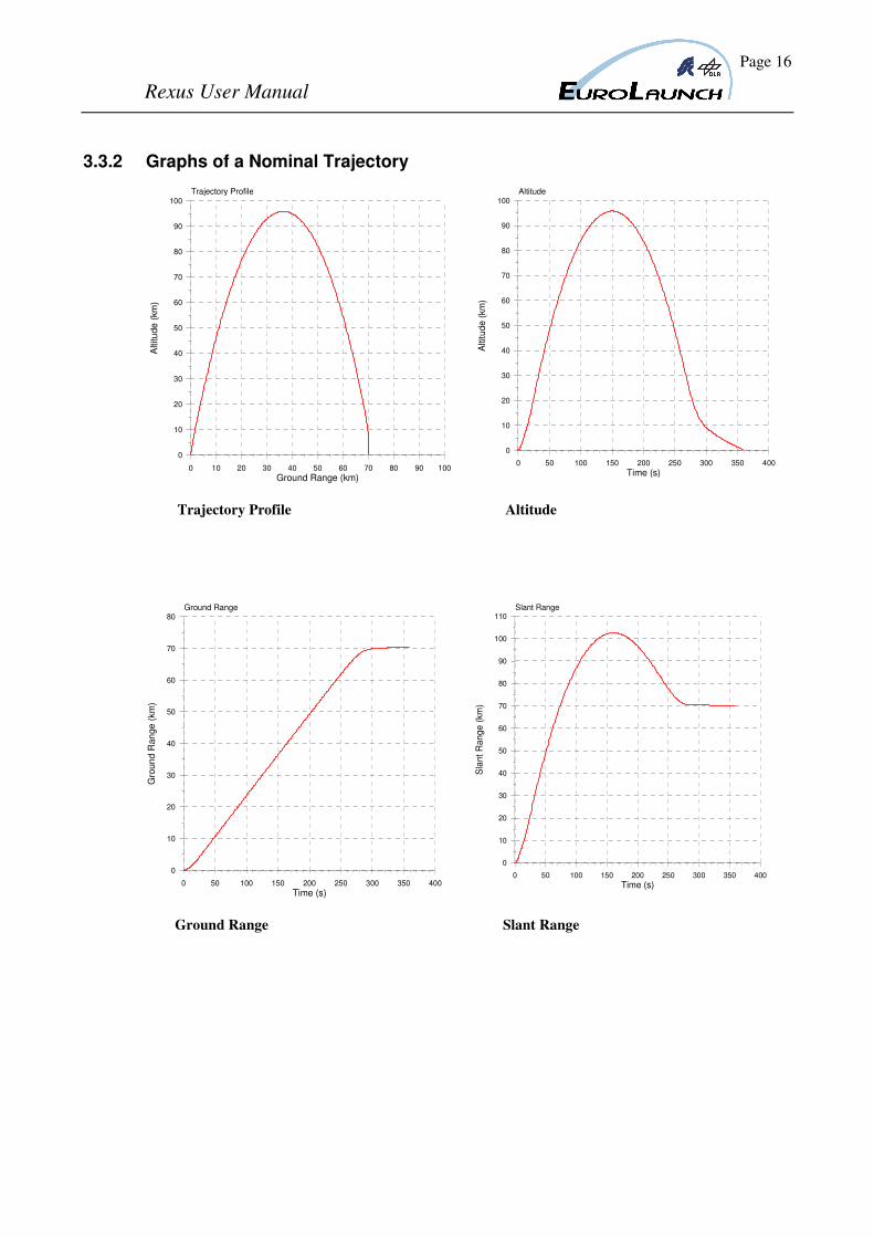
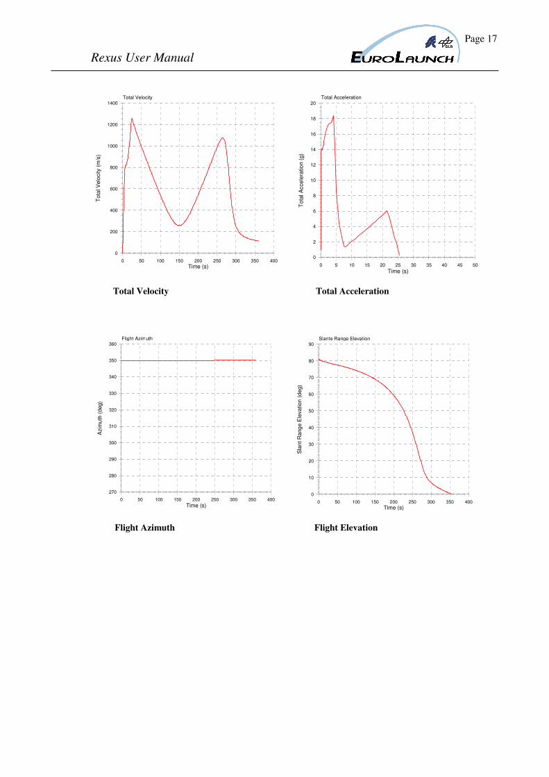
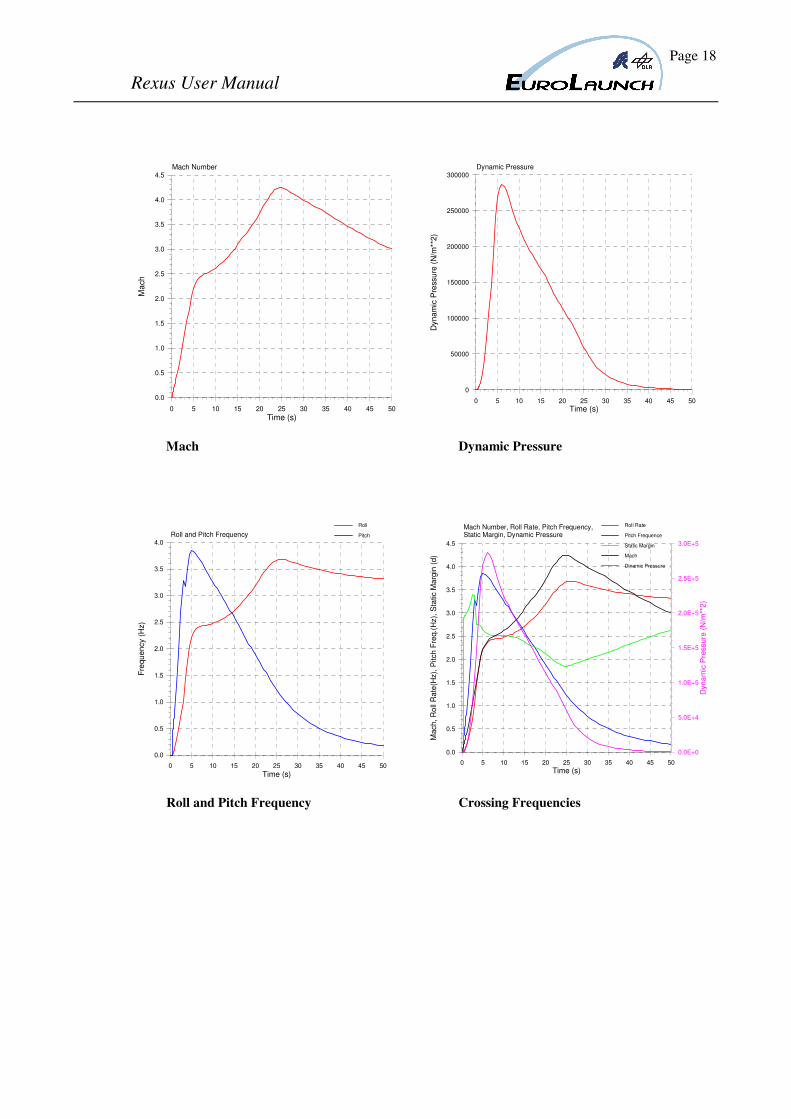
3.3.2 Graphs of a Nominal Trajectory
0 50 100 150 200 250 300 350 400
Time (s)
0
10
20
30
40
50
60
70
80
Gro
un
d R
an
ge (
km
)
Ground Range
0 50 100 150 200 250 300 350 400
Time (s)
0
10
20
30
40
50
60
70
80
90
100
110
Sla
nt
Ran
ge
(km
)
Slant Range
Ground Range Slant Range
0 10 20 30 40 50 60 70 80 90 100
Ground Range (km)
0
10
20
30
40
50
60
70
80
90
100
Altitu
de
(km
)
Trajectory Profile
0 50 100 150 200 250 300 350 400
Time (s)
0
10
20
30
40
50
60
70
80
90
100
Altitu
de
(km
)
Altitude
Trajectory Profile Altitude
Page 17
Rexus User Manual
0 50 100 150 200 250 300 350 400
Time (s)
0
200
400
600
800
1000
1200
1400T
ota
l V
elo
city (
m/s
)Total Velocity
0 5 10 15 20 25 30 35 40 45 50
Time (s)
0
2
4
6
8
10
12
14
16
18
20
Tota
l A
cce
lera
tio
n (
g)
Total Acceleration
Total Velocity Total Acceleration
0 50 100 150 200 250 300 350 400
Time (s)
270
280
290
300
310
320
330
340
350
360
Azim
uth
(deg)
Flight Azimuth
0 50 100 150 200 250 300 350 400
Time (s)
0
10
20
30
40
50
60
70
80
90
Sla
nt R
ang
e E
leva
tion
(d
eg)
Slante Range Elevation
Flight Azimuth Flight Elevation
Page 18
Rexus User Manual
0 5 10 15 20 25 30 35 40 45 50
Time (s)
0.0
0.5
1.0
1.5
2.0
2.5
3.0
3.5
4.0
4.5
Ma
ch
Mach Number
0 5 10 15 20 25 30 35 40 45 50
Time (s)
0
50000
100000
150000
200000
250000
300000
Dyn
am
ic P
ress
ure
(N
/m**
2)
Dynamic Pressure
Mach Dynamic Pressure
0 5 10 15 20 25 30 35 40 45 50
Time (s)
0.0
0.5
1.0
1.5
2.0
2.5
3.0
3.5
4.0
Fre
quency (
Hz)
Roll and Pitch Frequency
Roll
Pitch
0 5 10 15 20 25 30 35 40 45 50
Time (s)
0.0
0.5
1.0
1.5
2.0
2.5
3.0
3.5
4.0
4.5
Mach
, R
oll
Ra
te(H
z),
Pitch
Fre
q.(
Hz),
Sta
tic M
arg
in (
d)
Mach Number, Roll Rate, Pitch Frequency,Static Margin, Dynamic Pressure
0.0E+0
5.0E+4
1.0E+5
1.5E+5
2.0E+5
2.5E+5
3.0E+5
Dyn
am
ic P
ressu
re (
N/m
**2
)
Roll Rate
Pitch Frequence
Static Margin
Mach
Dinamic Pressure
Roll and Pitch Frequency Crossing Frequencies
Page 19
Rexus User Manual
3.4 The REXUS thermal environment
3.4.1 Pre-launch Phase
The integration of the modules and payload are made in normal room temperature 20±5
°C. After integration, the payload is mounted in the launch tower. The ambient temperature
during the transport can be low (down to -30 °C), depending on the outdoor temperature,
but the exposure time is short (5-10 minutes).
The thermal environment in the launch tower will be kept under control before launch. The
vehicle is in housing with an air temperature of 17±7 oC.
3.4.2 Count Down Phase
Experience shows that during count down, the experiment modules tend to see an increase
in temperature over time, especially if long holds are required. Some actions can be taken
in the launch tower to improve the situation, however it is recommended that heat sensitive
experiment modules, include a temperature regulation in the design. See also chapter 4.2
for thermal requirements.
3.4.3 Flight Phase
Thermal environment of the outer structure of a front-end positioned parallel bay module
on an Improved Orion motor flight can reach 110oC at 50 seconds after lift-off. Peak
temperatures above 200 °C are reached during re-entry phase. This will of course be
transferred to internal parts, especially items mounted on the skin.
3.4.4 Post-flight phase
After the impact, the payload will be subjected to snow and cold air in the impact area for a
period of typically one to two hours. The temperature during the season when REXUS is
launched is normally between 0 °C and -30 °C. Experiments with samples sensitive to low
temperatures after the flight, must be designed for these post flight conditions.
Page 20
Rexus User Manual
4 MECHANICAL DESIGN OF EXPERIMENTS
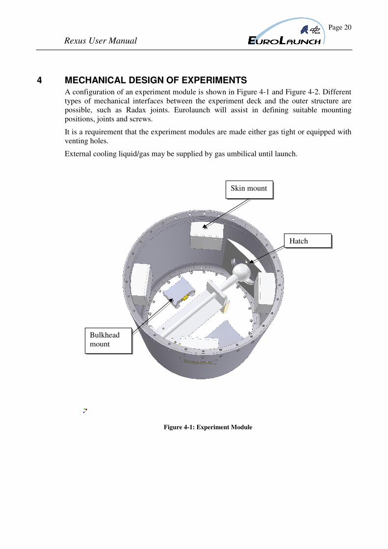
A configuration of an experiment module is shown in Figure 4-1 and Figure 4-2. Different
types of mechanical interfaces between the experiment deck and the outer structure are
possible, such as Radax joints. Eurolaunch will assist in defining suitable mounting
positions, joints and screws.
It is a requirement that the experiment modules are made either gas tight or equipped with
venting holes.
External cooling liquid/gas may be supplied by gas umbilical until launch.
Figure 4-1: Experiment Module
Skin mount
Hatch
Bulkhead
mount
Page 21
Rexus User Manual
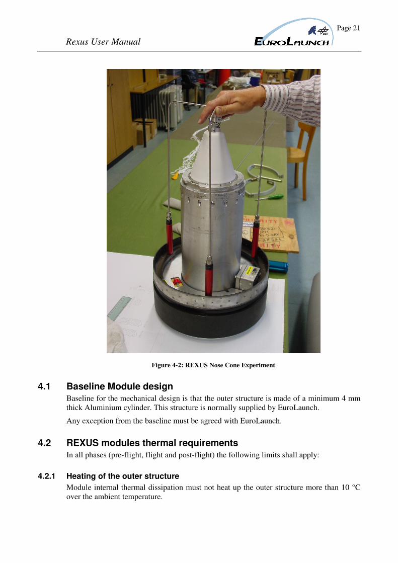
Figure 4-2: REXUS Nose Cone Experiment
4.1 Baseline Module design
Baseline for the mechanical design is that the outer structure is made of a minimum 4 mm
thick Aluminium cylinder. This structure is normally supplied by EuroLaunch.
Any exception from the baseline must be agreed with EuroLaunch.
4.2 REXUS modules thermal requirements
In all phases (pre-flight, flight and post-flight) the following limits shall apply:
4.2.1 Heating of the outer structure
Module internal thermal dissipation must not heat up the outer structure more than 10 °C
over the ambient temperature.
Page 22
Rexus User Manual
4.2.2 Temperature at the feed-through cable
Module internal thermal dissipation must not heat up the parts close to or in contact with
the feed-through cable to more than + 70 °C.
4.2.3 Heat radiation in the module interfaces
Module internal thermal dissipation must not heat up parts facing other modules to more
than +50 °C.
4.2.4 Convection between connecting modules
The heat transport through convection must be limited in such a way that the air
temperature at the module interfaces does not exceed the ambient temperature by more
than 10 °C.
An insulation deck, in both ends of the module, could be required to comply with these
requirements.
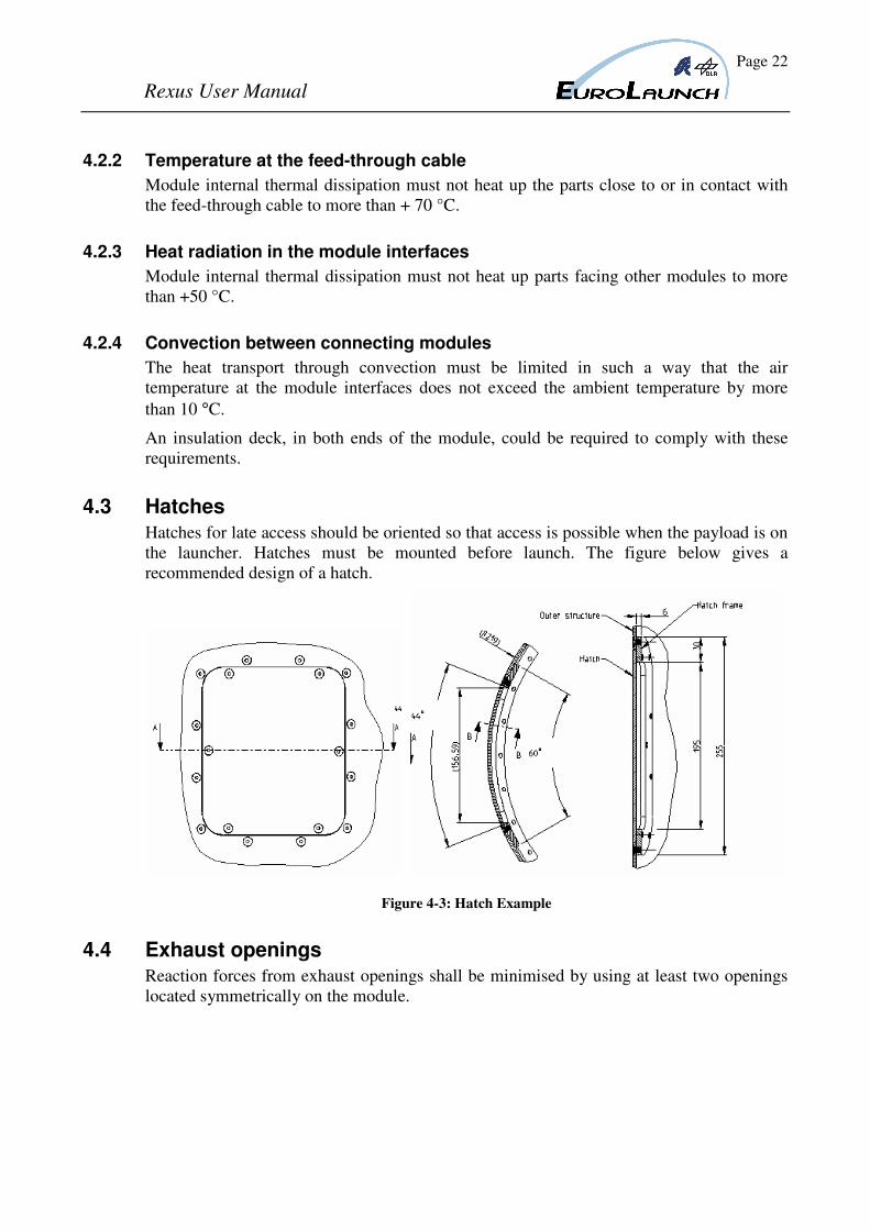
4.3 Hatches
Hatches for late access should be oriented so that access is possible when the payload is on
the launcher. Hatches must be mounted before launch. The figure below gives a
recommended design of a hatch.
Figure 4-3: Hatch Example
4.4 Exhaust openings
Reaction forces from exhaust openings shall be minimised by using at least two openings
located symmetrically on the module.
Page 23
Rexus User Manual
4.5 Dimensioning loads during launch, flight and recovery
The experiments should be dimensioned to withstand the loads during a complete flight
profile.
4.5.1 Acceleration
The typical longitudinal acceleration history (for an Improved Orion rocket motor
combination) is shown in shown in chapter 3.3.
4.5.2 Re-entry Loads
The typical deceleration during re-entry is not above 20 g.
4.5.3 Landing Velocity
The landing velocity is approximately 8 m/s. The shock at impact depends on the nature
of the ground surface. Nominally, the landing is gentle with no damage on the experiment
modules.
4.6 Mechanical Retroaction Forces from Experiments on the Payload
An estimation or measurement of the induced acceleration or vibration levels of each
experiment shall be presented to EuroLaunch at least four months before launch.
4.6.1 Vehicle Characteristics
Momentum wheels, cavities partially filled with liquids, etc. will only be accepted after a
successful analysis on the impact on the vehicle performance.
4.6.2 Movements
Any movements of components or samples in the module can disturb the payload
conditions.
These disturbances shall be kept to a minimum, for instance through counteracting
mechanical devices or symmetrical gas exhaust openings.
4.6.3 Vibrations
Vibrations induced by movement of components in the payload will also cause
disturbances on the flight conditions.
The vibration levels generated in the module shall be kept as low as possible. As a rule of
thumb, the module produced vibration levels should be lower than 5*10-5
(0-25 Hz). This
level changes from flight to flight and is depending on the experiment modules’ sensitivity
to vibrations.
Page 24
Rexus User Manual
4.7 Mass balance and mass properties
The centre of gravity of each module shall be as close as possible to the x-axis. Mass
balancing of the modules, adding ballast weights, does not have to be performed, since the
total payload will be mass-balanced, thereby saving total ballast weight. This work is
performed by EuroLaunch.
The accuracy should be as follows:
Total mass ±0.5 kg
Mass distribution ±0.25 kg per 10 cm
Moment of inertia Ix ±0.1 kg m2
Iy ±0.1 kg m2
Iz ±0.1 kg m2
Centre of gravity X ±2 cm
Y ±2 cm
Z ±2 cm
Page 25
Rexus User Manual
5 ELECTRICAL DESIGN OF EXPERIMENTS
5.1 General
The electrical interfaces between the experiments are limited to data and command wires
connecting each experiment to the REXUS Service Module RXSM. The lift off signal is
distributed via the communication interface.
The interface between the experiments and the SM is identical for all experiments. The TM
interface is described in chapter 5.2.
An electrical cabling scheme will be prepared for each payload configuration.
The feed through harness for REXUS will be designed and built by EuroLaunch.
5.2 Telemetry System
The REXUS telemetry system is designed and manufactured by Eurolaunch.
It consists of the TM/TC master, located in the RXSM and TM/TC users distributed in the
experiment part of the payload.
The maximum number of users in the experiment payload is 5. Each user is powered from
the RXSM.
The output from the main encoder modulates an S-band transmitter providing the ground
link.
TM/TC master to TM/TC user:
The interface between master and each user in the TM/TC system is implemented using
two serial connections, one in each direction. Each interface connection is a symmetrical
pair, driven by an RS-422 driver.
Type: Asynchronous serial link
Signal std: RS422
5.3 Telecommand System
The telemetry system incorporates a telecommand function. Each experiment module can
be individually addressed by ground commands. The telecommand receiver operates in the
L-band.
The telecommands and their characteristics must be specified and submitted to
EuroLaunch.
Page 26
Rexus User Manual
5.4 Interface Connector Description to REXUS Service Module
5.4.1 Objectives
Standard Interfaces has been implemented to make the communication between the PCM
System, Command System and the experiments easier. If one experimenter isn’t able to
include these standard interfaces in his experiment EuroLaunch may support him with the
tools (data acquisition unit) to be compliant with these standards.
The installed command and telemetry system delivers a fully transparent up and downlink
channel for each experiment. The same user software for controlling and monitoring of the
experiment data can be used during the test phase and during flight.
5.4.2 Interface Description Onboard
Each experiment obtains its own interface connector. On this connector all communication
lines, power lines and control lines are implemented. A DSUB 15 m connector is used to
perform the interface, and it has a standard pin allocation.
5.4.2.1 Telemetry Interface
A RS 422 interface is responsible for the transfer of the experiment data to the PCM
System. The baudrate must be adjusted to the maximum data throughput, while the
formatting, the failure recognizing and correction is in the responsibility of the
experimenter.
Baudrate: adjusted to the maximum data throughput, 38.4 kbaud standard
Format: 8 bits, 1 start and stop bit, no parity
If the experimenter is not able to implement a unit to perform the sampling of digital and
analogue data and to transfer them to the PCM System via a serial interface a so called data
acquisition unit could be made available by EuroLaunch.
5.4.2.2 Command Interface
A RS 422 interface supplies the appropriate commands to each experiment. The
formatting, failure recognizing and correction is also in the responsibility of the user.
Baudrate: 19200 Baud
Format: 8 bits, 1 start and stop bit, no parity
If the experimenter isn’t able to receive commands via a serial RS 422 interface a data
acquisition unit may be made available to receive the serial commands and convert these
commands into open collector outputs.
Page 27
Rexus User Manual
5.4.2.3 Power
The power (standard 28 V) is delivered by the service module. The supply voltage can vary
between 24 V and 35 V depending the condition of the onboard batteries.
The peak power consumption should not step over 3 Amps during switching, while the
mean value should be lower than 1 Amp. The power for each experiment can be controlled
by hard-line commands via umbilical or, if available, by RF commands during flight.
If a user needs an extraordinary power system he is responsible for the charging,
measurement of his batteries via umbilical lines.
5.4.2.4 Charging Capability
In case of internal batteries within the individual experiment, there is a charging line to
provide power (28-34V)@500mA to the experiment when the Service Module is switched
off.
This line is only for charging purposes, not for operating the experiment when the S/M is
switched off (in case of radio silence).
This line is protected with a diode to avoid reverse current and discharging.
5.4.2.5 Control Lines
The service module supplies 4 different control lines for each experiment which are
implemented as open collector outputs with the capability to drive 0.2 Amps for each
channel.
The 4 control lines are as follows:
a. Start of Recording/ Data Storage (SODS)
b. Lift-Off (LO)
c. Start of Experiment (SOE)
d. User defined Time Event (UTE) (optional)
An activation of the control lines means a sink current of up to 0.2 Amps. This sink current
could be used to switch a relay or to control a current through an optocoupler.
If using a relay the user is responsible to include a clamp diode close to the coil of the
relay.
Page 28
Rexus User Manual
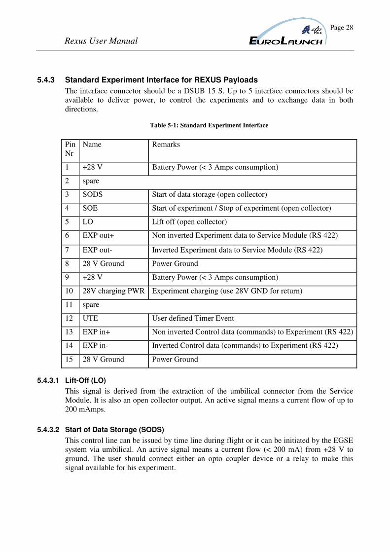
5.4.3 Standard Experiment Interface for REXUS Payloads
The interface connector should be a DSUB 15 S. Up to 5 interface connectors should be
available to deliver power, to control the experiments and to exchange data in both
directions.
Table 5-1: Standard Experiment Interface
5.4.3.1 Lift-Off (LO)
This signal is derived from the extraction of the umbilical connector from the Service
Module. It is also an open collector output. An active signal means a current flow of up to
200 mAmps.
5.4.3.2 Start of Data Storage (SODS)
This control line can be issued by time line during flight or it can be initiated by the EGSE
system via umbilical. An active signal means a current flow (< 200 mA) from +28 V to
ground. The user should connect either an opto coupler device or a relay to make this
signal available for his experiment.
Pin
Nr
Name Remarks
1 +28 V Battery Power (< 3 Amps consumption)
2 spare
3 SODS Start of data storage (open collector)
4 SOE Start of experiment / Stop of experiment (open collector)
5 LO Lift off (open collector)
6 EXP out+ Non inverted Experiment data to Service Module (RS 422)
7 EXP out- Inverted Experiment data to Service Module (RS 422)
8 28 V Ground Power Ground
9 +28 V Battery Power (< 3 Amps consumption)
10 28V charging PWR Experiment charging (use 28V GND for return)
11 spare
12 UTE User defined Timer Event
13 EXP in+ Non inverted Control data (commands) to Experiment (RS 422)
14 EXP in- Inverted Control data (commands) to Experiment (RS 422)
15 28 V Ground Power Ground
Page 29
Rexus User Manual
5.4.3.3 Start of experiment / Stop of experiment (SOE)
This control line can be issued by time line or by command during flight. It is also an open
collector output. An active signal means a current flow of up to 200 mAmps. The user
should connect either an optocoupler device or a relay to make this signal available for his
experiment.
5.4.3.4 User Defined Timer Event (UTE)
This control line can be issued by time line or by command during flight. It is also an open
collector output. An active signal means a current flow of up to 200 mAmps. The user
should connect either an optocoupler device or a relay to make this signal available for his
experiment.
5.4.4 Interface Description on Ground
The user of an experiment receives his experiment data via a RS 232 interface, and he can
control his experiment by sending commands via the same RS 232 interface over the
umbilical or over a RF command link, if available.
If a recorder is onboard it can be switched on just before lift-off. The SOE and the UTE
can be defined by the user, and they are controlled by time lines on board.
If necessary experiments can be switched off either by RF commands, or by time lines.
Reception of experiment data:
Baudrate: depending on data throughput
Format: 8 bits, 1 start and stop bit, no parity
Commanding of experiment:
Baudrate: 19 200 Baud
Format: 8 bits, 1 start bit and stop bit, no parity
5.5 Additional Batteries
EuroLaunch recommends using Ni-Metalhydride batteries and has a large experience in
using the SAFT brand of batteries on sounding rockets. Other brands that are possible to
use, but it is wise to contact the project manager for advice. Lithium batteries should not be
used if possible.
Recommended batteries:
Single use: SAFT LSH Series, (Lithium-thionyl chloride)
Rechargeable: SAFT Li-ION, Nickel Cadmium or Nickel Metal Hydride series.
Page 30
Rexus User Manual
5.6 Umbilicals
5.6.1 Orientation
The orientation of the umbilical shall be in accordance with EuroLaunch instructions.
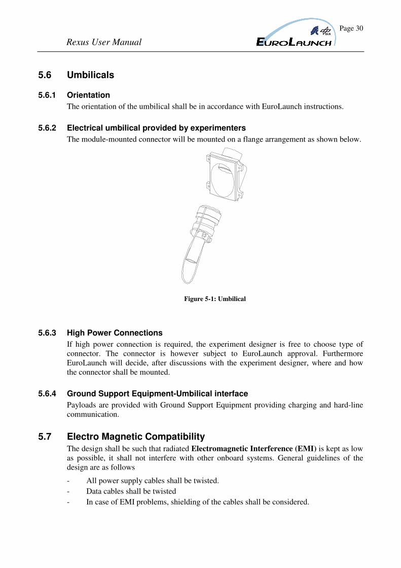
5.6.2 Electrical umbilical provided by experimenters
The module-mounted connector will be mounted on a flange arrangement as shown below.
Figure 5-1: Umbilical
5.6.3 High Power Connections
If high power connection is required, the experiment designer is free to choose type of
connector. The connector is however subject to EuroLaunch approval. Furthermore
EuroLaunch will decide, after discussions with the experiment designer, where and how
the connector shall be mounted.
5.6.4 Ground Support Equipment-Umbilical interface
Payloads are provided with Ground Support Equipment providing charging and hard-line
communication.
5.7 Electro Magnetic Compatibility
The design shall be such that radiated Electromagnetic Interference (EMI) is kept as low
as possible, it shall not interfere with other onboard systems. General guidelines of the
design are as follows
- All power supply cables shall be twisted.
- Data cables shall be twisted
- In case of EMI problems, shielding of the cables shall be considered.
Page 31
Rexus User Manual
6 EXPERIMENT REVIEWS AND TESTS
6.1 Kick-Off Meeting
The REXUS project Kick-Off Meeting shall be held right after the final selection of the
student experiments.
6.2 Preliminary Design Review, PDR
The Preliminary Design Review (PDR) ends the study phase (phase A/B). It will be at the
student training week. Minutes of meeting shall be written including an action item list.
6.3 Critical Design Review, CDR
In the phase C/D a Critical Design Review, CDR, is performed after the detailed design is
finished but before the manufacturing starts (2-3 months after PDR). Minutes of meeting
shall be written including an action item list. The minutes shall be forwarded to
EuroLaunch.
6.4 Progress Report / Mid Term Report
About two month after the CDR a Mid Term Report (MTR) has to be prepared by the
experimenter. This report shall guarantee a satisfied work progress. The report shall also
identify certain problems which are necessary to be solved prior to experiment delivery.
In the report the experimenter shall present the following points:
- Experiment development status
- Time schedule compatibility
- Experiment dimensions and weight
- Identification of problems
- List of hazard materials
- Approach to solve problems
- Interface compatibility
6.5 Vacuum test
Applicable for experiment to be used under vacuum conditions, but is also applicable to
verify that systems, mainly electrical, have nominal performance in absence of convective
cooling. This is the responsibility of the experimenter to perform.
Basic Procedure:
- The experiment shall be integrated and placed in a vacuum chamber (pressure
below 0.5 mBar).
- Experiment data shall be supervised and recorded during the test.
- The experiment shall be operating during lowering of the pressure in the vacuum
chamber. The module shall, if be in a similar mode as during the real ascent of the
REXUS.
Page 32
Rexus User Manual
- After the functional test/flight sequence has been performed it is recommended that
the module is kept operating for 15 minutes to detect any leakage/overheating
problems.
- When testing high voltage subsystems, corona effects shall be searched for in the
pressure interval 1-20 mBar.
6.6 Thermal test
The thermal test is mainly performed in order to verify a nominal function of the
experiment during the worst case temperatures during countdown and launch. The heating
of the outer structure during ascent is normally not included or tested. This is the
responsibility of the experimenter to perform.
Basic Procedure:
- The experiment shall be integrated and placed in a thermal chamber. The Ground
Support Equipment, GSE, shall be connected via the umbilical. The telemetry and
telecommand checkout system shall be connected via the interface harness.
- Module data shall be supervised and recorded during the test.
- The temperature shall preferably be measured in several places in the experiment.
- Low temperature test:
Adjust the temperature in the thermal chamber to +10 °C. When the measured
temperatures in the experiment have stabilised, perform a functional test/flight
sequence. Be aware of condensation problems if the test is performed in normal
humidity.
- High temperature test:
Adjust the temperature in the thermal chamber to +45 °C. When the measured
temperatures in the experiment have stabilised, perform a functional test/flight
sequence. During transition from low to high temperature, the module shall be
operating and data shall be recorded.
Page 33
Rexus User Manual
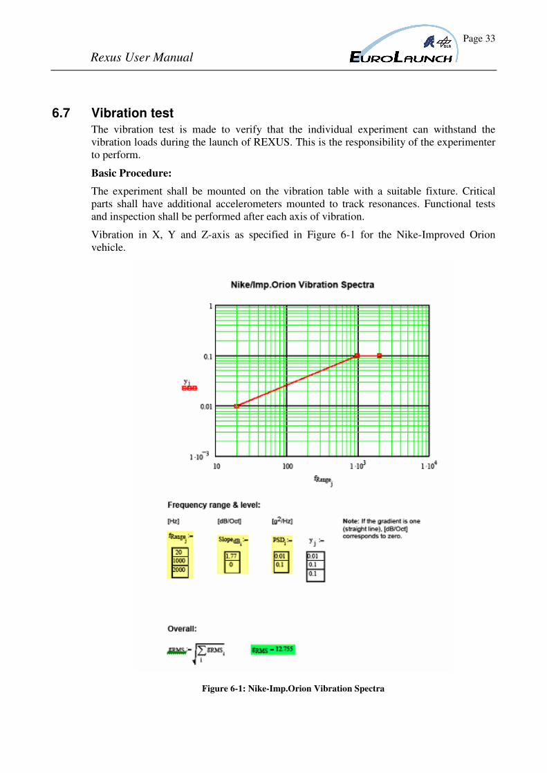
6.7 Vibration test
The vibration test is made to verify that the individual experiment can withstand the
vibration loads during the launch of REXUS. This is the responsibility of the experimenter
to perform.
Basic Procedure:
The experiment shall be mounted on the vibration table with a suitable fixture. Critical
parts shall have additional accelerometers mounted to track resonances. Functional tests
and inspection shall be performed after each axis of vibration.
Vibration in X, Y and Z-axis as specified in Figure 6-1 for the Nike-Improved Orion
vehicle.
Figure 6-1: Nike-Imp.Orion Vibration Spectra
Page 34
Rexus User Manual
6.8 Experiment Acceptance Review, EAR
The manufacturing phase should end with the Experiment Acceptance Test (EAT) after
delivery of the experiment. The EAT is similar to the Payload System Test (PST).
The EAT consist of:
- Experiment checkout /functional tests
- Experiment mass properties determination.
- Mechanical and electrical interface checkout
- Electrical Interface Test EIT
- Flight Simulation Test, FST
The EAT is performed by EuroLaunch together with the experiment responsible student.
6.8.1 Electrical Interface Test
See Chapter 6.9.6.
6.8.2 Flight Simulation Test
This test shall be performed with the payload in flight configuration as far as possible. The
test procedure shall include the count down procedure list and follow the nominal count
down timetable. It is also important that the experiment is in flight configuration and that
the PI is present.
It is important that the changes/modifications are restricted to a minimum, done to H/W or
S/W after the Flight Simulation Test. Non-conformances discovered during the test can of
course be corrected, but care must be taken to verify that no further malfunctions are
induced by the correction. All corrections after the FST shall be documented and reported
during a relevant review.
Basic Procedure
- The experiment payload shall be integrated and in flight configuration. The Ground
Support Equipment, EGSE, shall be connected via the umbilical. The telemetry and
telecommand checkout system shall be connected via the interface harness.
- Module data shall be supervised and recorded during the test.
- A nominal realistic count down procedure shall be followed, including at least one
payload checkout. Switching between external and internal power shall be done at
the nominal time (T-2 minutes).
- At lift-off, the umbilical shall be disconnected and the payload shall be controlled
via TM/TC. The experiment sequence shall be as close as possible to the flight
sequence.
It is also useful to perform a test with “unexpected” performance and to train
countermeasures.
Examples of abnormal tests are:
- Interruption in internal power supply
Page 35
Rexus User Manual
- Reset of onboard processor
- Malfunction of subsystems e.g. illumination is suddenly switched off
6.9 PAYLOAD ASSEMBLY AND INTEGRATION TESTS
This chapter deals with the assembly of the payload and the tests conducted on the
integrated payload. It also defines the requirements regarding the status of the module by
delivery of it to the Payload Assembly and Integration Tests (AIT).
The payload integration tests are performed at EuroLaunch premises and/or premises
leased by EuroLaunch. Nominally, these tests start five weeks before the planned start of
the launch campaign.
At the start of the payload integration tests, all experiments comprising the REXUS
payload must be made available to SSC. During some of the tests to be performed,
technical personnel trained to handle the experiment and ground support equipment shall
accompany the experiment. During the AIT, the experiment must be in flight
configuration. If use of dummies is required, this must be agreed by EuroLaunch.
6.9.1 Experiment Status by Delivery
EuroLaunch recommends the experimenter to conduct the following
qualification/acceptance tests on module level as a minimum:
-electrical/functional tests
-vibration tests
-environmental tests
-mechanical interface checkout
-electrical interface checkout
6.9.2 Experiment Incoming Inspection
All Experiment mechanical and electrical interfaces will be inspected at delivery to the
AIT.
6.9.3 Payload Assembly
The experiment, other modules and subsystems will in due order be mated to the payload.
All the mechanical and electrical interfaces will be checked and tested systematically
during the assembly in accordance with chapter 6.9.5 and 6.9.6.
6.9.4 Payload System Tests
The Payload System tests comprises
- Module checkout
- Payload mass properties determination and balancing
- Payload spin test
- System Electrical test 1 + EMI-check
- System Electrical test 2
- Flight Simulation test
Page 36
Rexus User Manual
6.9.5 Mechanical Interface Test
The mechanical joints are checked by mounting the module to the interfacing modules.
Orientation of umbilicals, feed-through harness, venting holes, etc is checked. This test is
performed by EuroLaunch during the payload assembly.
6.9.6 Electrical Interface Test
The electrical interface test will verify the compatibility of the interfaces and the
functioning of the concerned hardware. Interface compatibility for critical signals,
protection automatisms and voltage regulations will be checked systematically during
assembly. Detailed procedures have to be defined for every unique module/subsystem.
The test is performed by EuroLaunch.
6.9.7 Module Checkout
The module is connected to the telemetry system and all channels used are checked with
the module powered and simulating experiments.
The test is performed by EuroLaunch and the Experiment responsible personnel.
6.9.8 Mass Properties and Balancing
The mass properties of the payload are measured and aligned. The following
measurements are performed by EuroLaunch:
- Payload Mass
- Centre of gravity
- Spin
- Moments of inertia
6.9.9 Spin test
During the balancing the payload is subject to ~3Hz spin for several minutes.
6.9.10 Bend Test
A bend test is normally not performed. But if necessary the payload will be fixated at the
payload/rocket motor interface and a force will be applied perpendicular to the structure
giving a torque to the payload/rocket motor interface. The deflection will be measured at
three positions along the payload body.
These tests are, if needed performed by EuroLaunch.
6.9.11 System Electrical Test 1 and EMI-check
These tests shall be performed with all flight hardware electrically operating and as far as
possible, operating in their flight configuration.
Telemetry transmission will be done first via cable and then via the telemetry transmitter.
All signals will be verified at the telemetry ground station. All subsystems shall be
monitored via the dedicated EGSE.
Page 37
Rexus User Manual
These tests are performed by EuroLaunch together with experiment responsible personnel.
6.9.12 Payload vibration Test
A complete vibration test is normally not performed.
6.9.13 Flight Simulation Test
The payload will be ready for the FST after successful results in the tests above.
Umbilicals shall be connected and the payload shall be in vertical position. Each module
shall be monitored and controlled by the module ground support equipment.
When all modules are operating nominally, a complete count-down and flight sequence is
performed.
All telemetry and telecommand signals will be recorded in the telemetry ground station,
during the test.
6.10 Flight Acceptance Review
Upon completion of payload integration tests described in chapter 6.9, the Flight
Acceptance Review, FAR shall be held.
The result from the tests shall be reviewed and problems will be discussed.
The objective of the FAR is to obtain system acceptance and to authorise start of the
campaign. Agreements shall specify whether to proceed on schedule or not, if the FAR is
unsuccessful due to failure of any experiment.
6.11 Flight Readiness Review
The launch readiness review is conducted by the EuroLaunch co-ordinator at campaign and
after completion of experiment module preparation, payload integration and test, payload
integration on launcher, GSE installation in blockhouse, payload checkout, ground support
stations checkout and test count down.
The purpose of the meeting is:
- to authorise start of the countdown phase i.e. the launch.
- to ensure that all ground and payload service systems essential for a successful
launch, flight and recovery are operating nominally. For this each appointed system
responsible shall give a status report at the meeting.
- to ensure that all experiments are ready for the flight. For this, each appointed
experiment module manager shall give a status report at the meeting. In addition,
the PI is requested to state the operative status of the experiment.
- to review the count down list
- to inform all relevant personnel of the safety regulations applicable during the
count down phase.
to inform all relevant personnel of general arrangements implied during the count down
phase (canteen hours, information systems etc.).
Page 38
Rexus User Manual
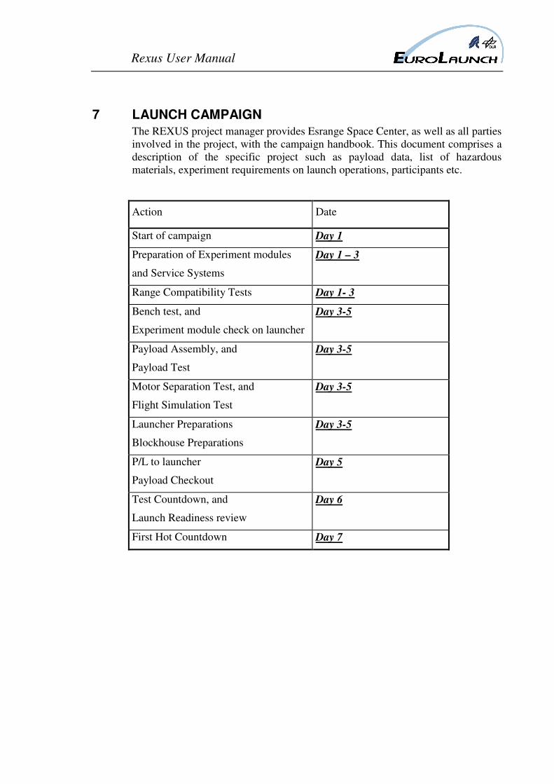
7 LAUNCH CAMPAIGN
The REXUS project manager provides Esrange Space Center, as well as all parties
involved in the project, with the campaign handbook. This document comprises a
description of the specific project such as payload data, list of hazardous
materials, experiment requirements on launch operations, participants etc.
Action Date
Start of campaign Day 1
Preparation of Experiment modules
and Service Systems
Day 1 – 3
Range Compatibility Tests Day 1- 3
Bench test, and
Experiment module check on launcher
Day 3-5
Payload Assembly, and
Payload Test
Day 3-5
Motor Separation Test, and
Flight Simulation Test
Day 3-5
Launcher Preparations
Blockhouse Preparations
Day 3-5
P/L to launcher
Payload Checkout
Day 5
Test Countdown, and
Launch Readiness review
Day 6
First Hot Countdown Day 7
Page 39
Rexus User Manual
7.1 Description of Esrange Space Center
All the necessary information for a user of Esrange can be found in the Esrange
Users’s handbook, Ref.(1). Its main contents are:
-Range description (capabilities, layout, environment...)
-Range administration (communications, accommodation, freight, supplies...)
-Safety regulations
-Instrumentation (telemetry, tracking, observation, scientific...)
-Operations(assembly, checkout, flight control, recovery, requirements,
procedures, cost...)
-Satellite facilities
7.2 Assembly of rockets and payloads
7.2.1 Assembly of rockets
All assembling and preparations of the rockets are taken care of by the
EuroLaunch launch team.
7.2.2 Assembly and checkout of payloads
Payload assembly and preparations are conducted by the REXUS project manager
together with EuroLaunch staff. Working space in the launching area will be
allocated by Esrange.
7.3 Countdown and Launch
During the count down phase important count down information is displayed on
“PA video monitors” at various locations of the range.
The count down phase starts with the test count down. It is normally executed
during normal working hours. During the test count down, all payload events up
to lift off shall be executed, late access activities shall be executed, all supporting
ground facilities are operating. Dummy units may be used during the test count
down but requires Eurolaunch approval.
Normally the count down payload events starts at 3 hours before launch.
After completion of the preparatory work and the test count down, the FRR is
held, see chapter 6.11. Pending the outcome of the test count down, and the
discussions during the FRR, the Hot Count Down list may be adjusted.
Nominally, the first “Hot Count Down” is started the day after the test count
down. The nominal lift off time is planned for. 05.00 to 20.00 local time. The
launch window is determined by the payload preparation time, hold requirements
and the time of daylight.
The decision to start the count down is taken at a weather briefing immediately
before planned start of count down. The decision is based on dedicated weather
forecasts and wind data obtained by weather balloons released from Esrange. If
Page 40
Rexus User Manual
the weather conditions are unsuitable for launching the vehicle, the launch will be
delayed until the flight conditions are fulfilled.
7.4 Recovery
The helicopters are equipped with tracking receivers for the payload beacon
signal, and can also be equipped with a payload TM receiver for data reception of
the payload’s GPS position.
During the flight, the payload trajectory will be tracked by means of the
transmitted GPS-data and by use of a slant range system in the TM ground
stations.
During the descent of the payload, the prediction on the impact point co-ordinates
is reported to the helicopters from Esrange. The helicopters start their localisation
operation immediately after the impact. At the impact site, the helicopter crew
disassembles time critical samples from the payload for quickest possible return to
the range laboratories. If early recover is required, a second helicopter is acquired
for carrying the payload back to the range.
The whole operation is normally completed within two hours after launch.
After the recovery, a Post Flight Meeting is held to debrief the flight and a short
flight performance report is stated.
Page 41
Rexus User Manual
8 EXPERIMENT QUALITY ASSURANCE
EuroLaunch major concern of QA on experiment level is that the experiment shall
fulfil the interface requirements and that the module can fly in a REXUS payload
without jeopardising the performance of the other systems or experiments. In
addition, EuroLaunch has a strong concern that the experiments shall perform
nominally.
The following advice reflects these concerns.
8.1 Materials
In addition to normal concerns when choosing materials, special attention shall be
paid to out gassing phenomena due to vacuum environment during flight.
As an aid the ESA-document PSS-07 (QRM-01) may be used.
8.2 Components
All electrical and mechanical components must have a reliability that is consistent
with the overall reliability of the payload. For electronic components, MIL-std
specified types are recommended.
8.3 Additional quality topics
In addition to the QA-topics above, the following topics shall be treated if
required by EuroLaunch:
8.3.1 Procured products and audits
Careful planning of the procurement and manufacturing must be made for
identification of long lead items. Preferably, a flow chart shall be made which
shows the sequence of operations.
8.3.2 Manufacturing control and inspection
For the manufacturing and inspection of critical processes, the personnel should
be certified in applicable areas, such as:
• Manual soldering according to ESA PSS-01-708
• Crimping of connections according to ESA PSS-01-726
Specific requirements of the project or product concerning cleanliness,
contamination and environment shall be stated in the Technical Specification.
When positioning the parts or components, the sensitivity to, heating, ESD and
electrical disturbances shall be considered.
Connectors shall be well marked and preferably keyed
Page 42
Rexus User Manual
8.3.3 Re-used Item
It is important to consider the complete history of the re-used item, by consulting
the hardware logbook or former project log-book; to be sure that it does not
include any hidden failures.
8.3.4 Availability and Maintainability
Spare parts for components susceptible of failure, shall be available during the
payload AIT and the launch campaign. The design shall allow for easy and fast
replacements of such components.
8.3.5 Handling, storage and packing
ESD susceptible components shall be handled in ESD protected environment.
Before transport, the product shall be thoroughly packed to withstand the expected
loads. The use of a bump recorder is recommended.
8.4 Personnel Safety
The REXUS experiments and dedicated equipment must fulfil safety requirements
according to Swedish law. The Swedish Work Environment Act is a general act
that is backed up by special laws and regulations in different fields. The Swedish
work environment authority issues these regulations.
Special provisions apply (among others) to the following fields:
Explosives
Inflammable material
Chemical hazards
Electrical facilities
Radiological work
All the above mentioned laws and regulations are available at
www.av.se/inenglish/lawandjustice/workact
The experimenter shall state that the module fulfils the applicable requirements
and establish a list of hazardous materials, which shall be communicated to
EuroLaunch no later than the MTR. This information shall always accompany the
experiment.
8.5 Safety at Esrange Space Center
The Safety Regulations that applies at Esrange may be found in Esrange Space
Center Safety Manual. Ref. [3]. It is a requirement that all personnel participating
in the campaign shall have read the safety regulation in Ref. [3] prior to their
arrival at Esrange Space Center.
Page 43
Rexus User Manual
9 COORDINATE SYSTEM DEFINITION
This chapter will give an overview on the coordinate systems that are used for a
REXUS onboard sensor, GPS and tracking systems. Knowledge about the
coordinate definition and transformations is important for the analysis of sensor
data during the flight and for the post flight analysis. The following table lists the
used coordinate systems.
Table 9-1 Coordinate Systems
ECI Earth Centred Inertial
ECEF Earth Centred, Earth Fixed
WGS84 World Geodetic System 1984
LTC Local Tangent Coordinate System
VCVF Vehicle Carried Vertical Frame
9.1 Earth Centered Inertial System (ECI)
This system originates ate the center of the Earth, as the name implies, and is
designated with the letters xECI, yECI and zECI. The fundamental plane is the Earth
equator. The xECI-axis points towards the vernal equinox. The yECI-axis is 90°
North Pole. This coordinates system is not rotating. It is assumed to be fixed
inertial in space. See Figure 9-1.
Before giving a definition of the vernal equinox, some expressions of the Earth
motion around the Sun have to be explained. The ecliptice is defined as the mean
plane of the Earth’ orbit around the Sun. The term comes from the fact that
eclipses of the Moon occur only when the Moon is close enough to this plane and
is between the Earth and the Sun. When the Sun is viewed from Earth, it appears
to move along the ecliptic. It does not move exactly on the ecliptic because this
path is defined as the mean plane of the Earth’s orbit. The Earth’s equatorial plane
extends the equator from the Earth. The angle between the Earth’s mean equator
and the ecliptic is called the obliquity of the ecliptic ε. This angle is about 23.5°,
although it does vary slightly over time due to perturbations. The line of
intersection of the two planes is called the line of nodes, like for the satellite orbit
plane and the Earth’s equatorial plane. The Sun occupies a position along this
intersection twice a year and they are called equinoxes1, vernal equinox when the
Sun is at the ascending node2 and the autumnal equinox when the Sun is at the
descending node3. The seasons cited are for the Northern hemisphere. When the
Sun is at an equinox, the Earth experiences equal times of day and night because
1
Equinox originates in the Latin root aequinoctium meaning equal day and night 2 In spring about March 21
3 In autumn about September 23
Page 44
Rexus User Manual
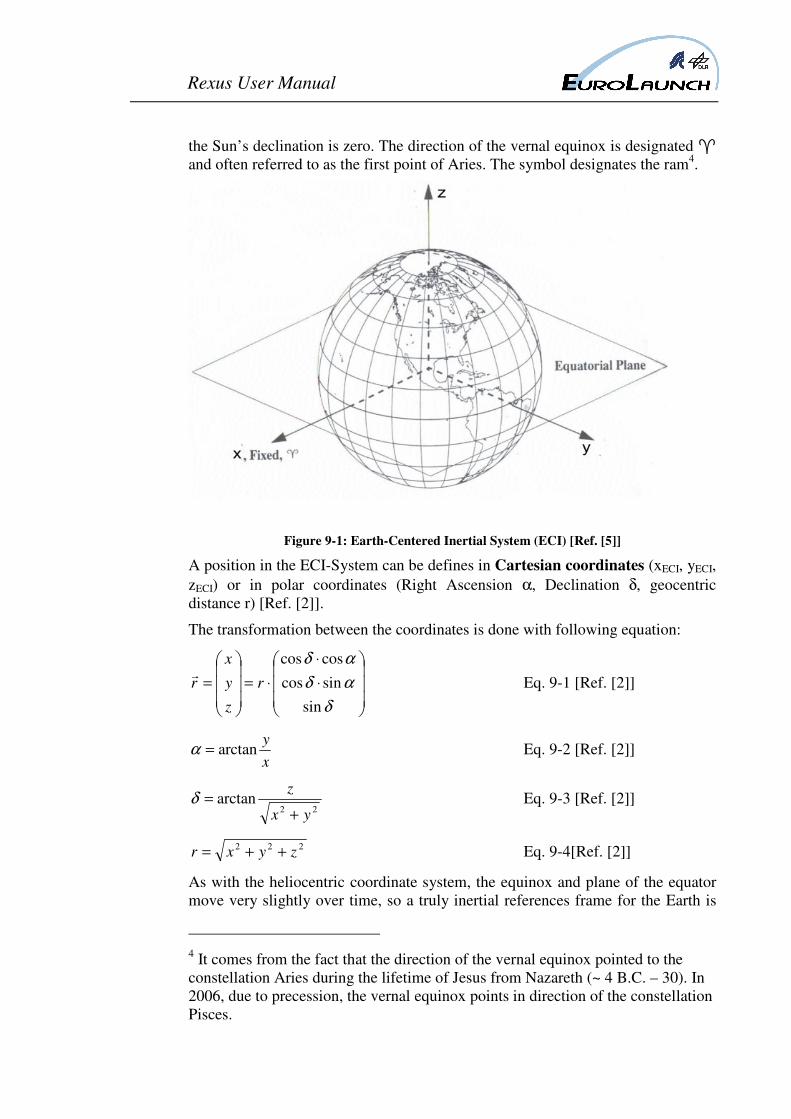
the Sun’s declination is zero. The direction of the vernal equinox is designated �
and often referred to as the first point of Aries. The symbol designates the ram4.
Figure 9-1: Earth-Centered Inertial System (ECI) [Ref. [5]]
A position in the ECI-System can be defines in Cartesian coordinates (xECI, yECI,
zECI) or in polar coordinates (Right Ascension α, Declination δ, geocentric
distance r) [Ref. [2]].
The transformation between the coordinates is done with following equation:
⋅
⋅
⋅=
=
δ
αδ
αδ
sin
sincos
coscos
r
z
y
x
rr
Eq. 9-1 [Ref. [2]]
x
yarctan=α Eq. 9-2 [Ref. [2]]
22arctan
yx
z
+=δ Eq. 9-3 [Ref. [2]]
222zyxr ++= Eq. 9-4[Ref. [2]]
As with the heliocentric coordinate system, the equinox and plane of the equator
move very slightly over time, so a truly inertial references frame for the Earth is
4 It comes from the fact that the direction of the vernal equinox pointed to the
constellation Aries during the lifetime of Jesus from Nazareth (~ 4 B.C. – 30). In
2006, due to precession, the vernal equinox points in direction of the constellation
Pisces.
Page 45
Rexus User Manual
impossible to realize. An inertial coordinate system can be almost achieved if it
refers to a particular epoch5 and it is specified how the vectors are transformed to
and from this time. Calculations that transform vectors to and from this epoch are
usually called Reduction Formulas.
The ECI reference system for the REXUS data is the J2000.0 system. This is
used since 1984. The xECI axis points in direction of the mean vernal equinox and
the zECI axis points in direction of the mean rotation axis of the Earth on January
1, 2000 at 12:00:00:00 TDB which coreresponds to a Julian date JD 2451545.0.
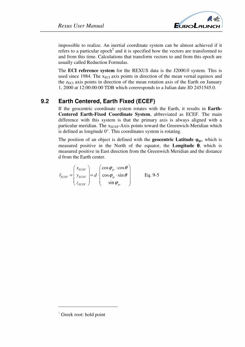
9.2 Earth Centered, Earth Fixed (ECEF)
If the geocentric coordinate system rotates with the Earth, it results in Earth-
Centered Earth-Fixed Coordinate System, abbreviated as ECEF. The main
difference with this system is that the primary axis is always aligned with a
particular meridian. The xECEF-Axis points toward the Greenwich-Meridian which
is defined as longitude 0°. This coordinates system is rotating.
The position of an object is defined with the geocentric Latitude φgc, which is
measured positive in the North of the equator, the Longitude θθθθ, which is
measured positive in East direction from the Greenwich Meridian and the distance
d from the Earth center.
cos cos
cos sin
sin
ECEF gc
ECEF ECEF gc
ECEF gc
x
r y d
z
ϕ θ
ϕ θ
ϕ
⋅
= = ⋅ ⋅
r Eq. 9-5
5
Greek root: hold point
Page 46
Rexus User Manual
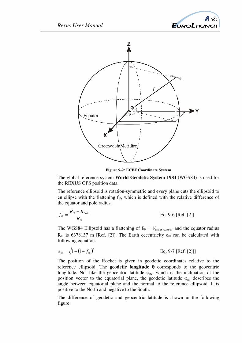
Figure 9-2: ECEF Coordinate System
The global reference system World Geodetic System 1984 (WGS84) is used for
the REXUS GPS position data.
The reference ellipsoid is rotation-symmetric and every plane cuts the ellipsoid to
en ellipse with the flattening f⊕, which is defined with the relative difference of
the equator and pole radius.
⊕
⊕⊕
−=
R
RRf Pole Eq. 9-6 [Ref. [2]]
The WGS84 Ellipsoid has a flattening of f⊕ = 257223563.2981 and the equator radius
R⊕ is 6378137 m [Ref. [2]]. The Earth eccentricity e⊕ can be calculated with
following equation.
( )211 ⊕⊕ −−= fe Eq. 9-7 [Ref. [2]]]
The position of the Rocket is given in geodetic coordinates relative to the
reference ellipsoid. The geodetic longitude θθθθ corresponds to the geocentric
longitude. Not like the geocentric latitude φgc, which is the inclination of the
position vector to the equatorial plane, the geodetic latitude φgd describes the
angle between equatorial plane and the normal to the reference ellipsoid. It is
positive to the North and negative to the South.
The difference of geodetic and geocentric latitude is shown in the following
figure:
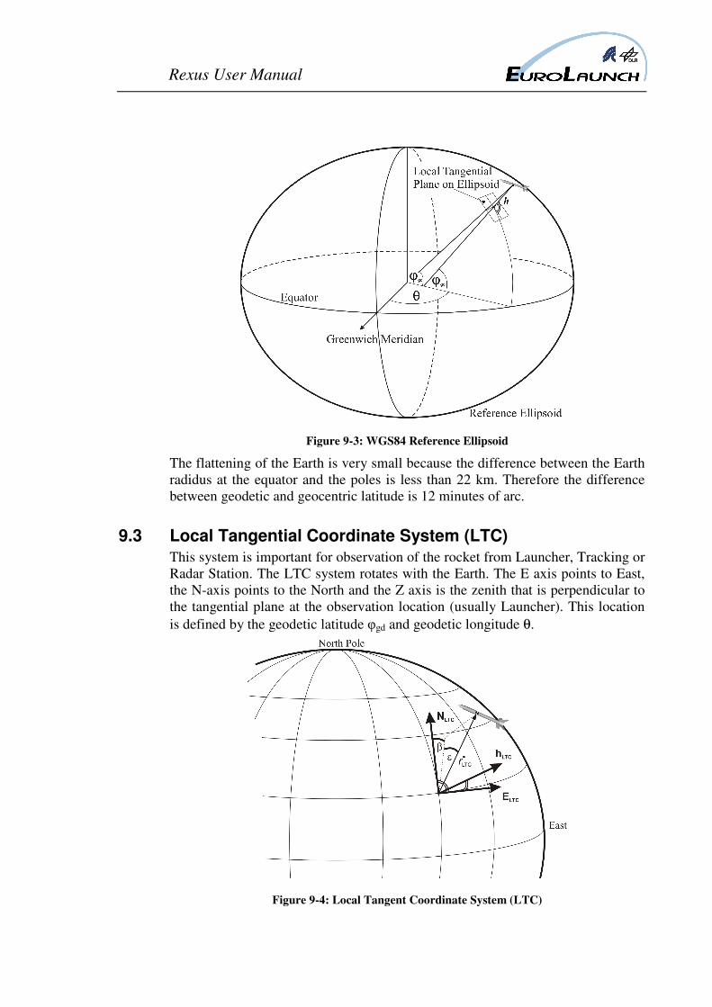
Page 47
Rexus User Manual
Figure 9-3: WGS84 Reference Ellipsoid
The flattening of the Earth is very small because the difference between the Earth
radidus at the equator and the poles is less than 22 km. Therefore the difference
between geodetic and geocentric latitude is 12 minutes of arc.
9.3 Local Tangential Coordinate System (LTC)
This system is important for observation of the rocket from Launcher, Tracking or
Radar Station. The LTC system rotates with the Earth. The E axis points to East,
the N-axis points to the North and the Z axis is the zenith that is perpendicular to
the tangential plane at the observation location (usually Launcher). This location
is defined by the geodetic latitude φgd and geodetic longitude θ.
Figure 9-4: Local Tangent Coordinate System (LTC)
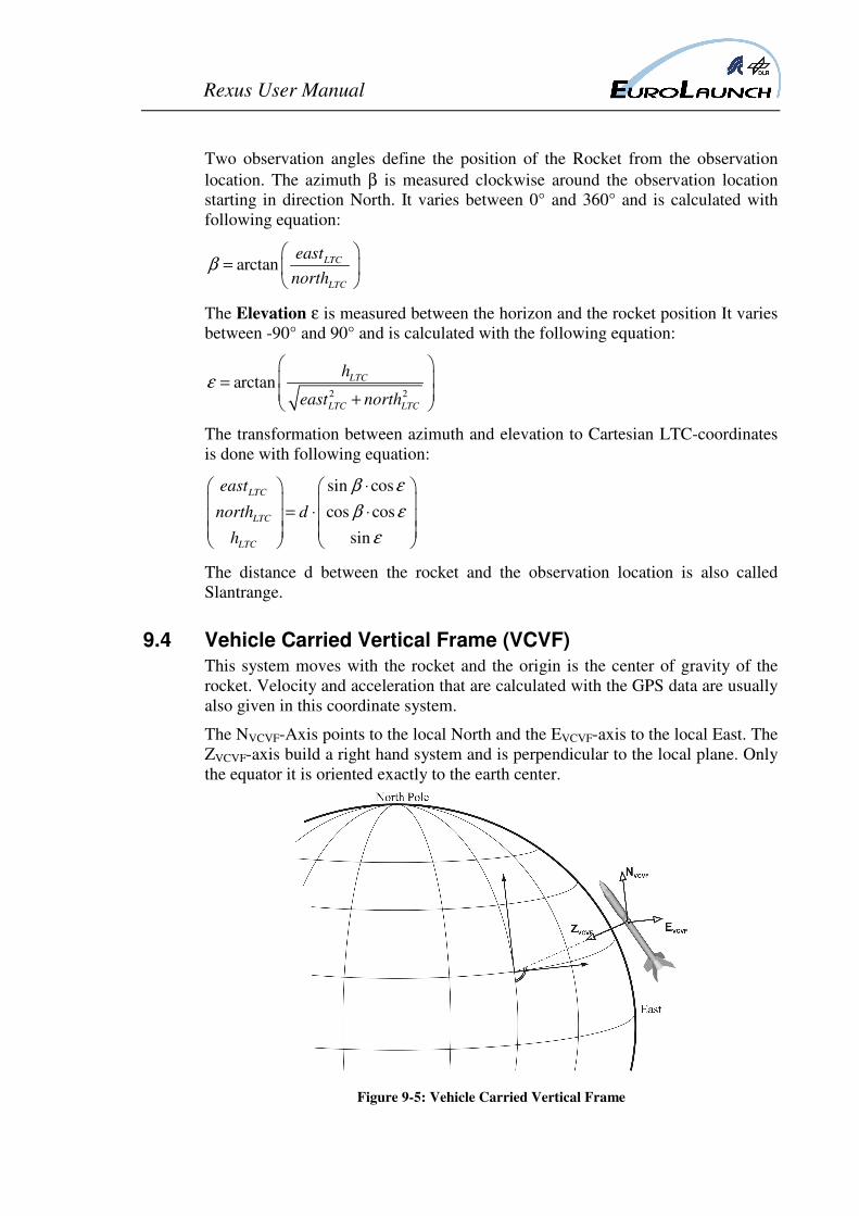
Page 48
Rexus User Manual
Two observation angles define the position of the Rocket from the observation
location. The azimuth β is measured clockwise around the observation location
starting in direction North. It varies between 0° and 360° and is calculated with
following equation:
arctan LTC
LTC
east
northβ
=
The Elevation ε is measured between the horizon and the rocket position It varies
between -90° and 90° and is calculated with the following equation:
2 2arctan LTC
LTC LTC
h
east northε
= +
The transformation between azimuth and elevation to Cartesian LTC-coordinates
is done with following equation:
sin cos
cos cos
sin
LTC
LTC
LTC
east
north d
h
β ε
β ε
ε
⋅
= ⋅ ⋅
The distance d between the rocket and the observation location is also called
Slantrange.
9.4 Vehicle Carried Vertical Frame (VCVF)
This system moves with the rocket and the origin is the center of gravity of the
rocket. Velocity and acceleration that are calculated with the GPS data are usually
also given in this coordinate system.
The NVCVF-Axis points to the local North and the EVCVF-axis to the local East. The
ZVCVF-axis build a right hand system and is perpendicular to the local plane. Only
the equator it is oriented exactly to the earth center.
Figure 9-5: Vehicle Carried Vertical Frame
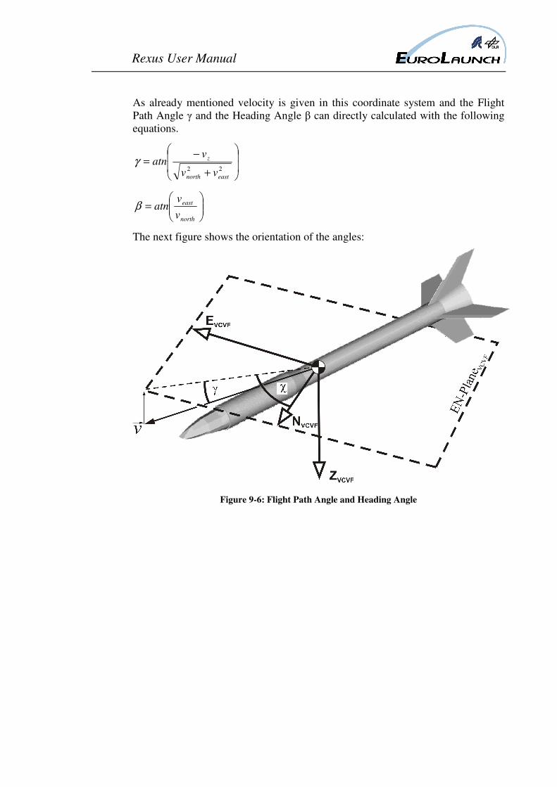
Page 49
Rexus User Manual
As already mentioned velocity is given in this coordinate system and the Flight
Path Angle γ and the Heading Angle β can directly calculated with the following
equations.
+
−=
22
eastnorth
z
vv
vatnγ
=
north
east
v
vatnβ
The next figure shows the orientation of the angles:
Figure 9-6: Flight Path Angle and Heading Angle