active mine batteries with long shelf-life 1. …
TRANSCRIPT

AD-A245 052
NAVSWC TR 91-20
ACTIVE MINE BATTERIES WITH LONG SHELF-LIFE
1. DEVELOPMENT OF LI-ION CONDUCTINGPOLYMERIC ANODE FILMS
BY K. M. ABRAHAM, D. M. PASQUARIELLO, AND M. HART(EtC LABORATORIES, INC.)
AND
W. P. KILROY (NA VS WC)
FOR NAVAL SURFACE WARFARE CENTER O-TICRESEARCH AND TECHNOLOGY DEPARTMENT $ rCT
10 April 1991
02 1 9 092Approved for public release; distribution is unlimited. 92-0 1000
NAVAL SURFACE WARFARE CENTERDahlgren, Virginia 22448-5000 0 Silver Spring, Maryland 20903-5000

NAVSWC TR 91-20
ACTIVE MINE BATTERIES WITH LONG SHELF-LIFE
I. DEVELOPMENT OF LI-ION CONDUCTINGPOLYMERIC ANODE FILMS
BY K. M. ABRAHAM, D. M. PASQUARIELLO, AND M. HART
(EIC LABORATORIES, INC.)
AND
W. P. KILROY (NAVSWC)
FOR NAVAL SURFACE WARFARE CENTERRESEARCH AND TECHNOLOGY DEPARTMENT
10 April 1991
Approved for public release; distribution is unlimited.
NAVAL SURFACE WARFARE CENTERDahlgren, Virginia 22448-5000 * Silver Spring, Maryland 20903-5000

NAVSWC TR 91-20
FOREWORD
This report describes some initial studies to develop Li-ion conducting polymer filmsto improve the performance of lithium anodes during extended storage of active Li/SOCI2cells.
This work is part of a collaborative effort between the Naval Surface Warfare Center(NAVSWC) and EIC Laboratories, Inc., to increase the performance of Li/SOCI2 batteriesto meet the operational requirements of new Navy mines.
Funding for this effort was provided by the NAVSWC Independent ExploratoryDevelopment program and the Navy SBIR program. We wish to acknowledge theassistance of D. Wilson (NAVSWC SBIR manager), B. Kirk (NAVSEA), and G. Leineweber(NAVSWC Mines Program) and their continued interest in improving lithium batterytechnology.
Approved by:
CARL E. MUELLER, HeadMaterials Division
Accession ForMIS . T- & I
L JD1T T"-
t,
NAVSWC TR 91-20
CONTENTS
Chatera
1 INTRODUCTION .............................................................. 11.1 CELL FABRICATION AND STORAGE CONDITIONS .... ...... 21.2 MECHANICAL NATURE OF MEEP ............................................ 31.3 ELECTROLYTE PURITY ........................................................... 31.4 COATING CONSISTENCY ......................................................... 3
2 EXPERIMENTAL PROCEDURES ........................................................ 42.1 M ATERIALS ................................................................................ 42.2 PROCEDURES ........................................................................... 4
3 R ES U LTS ............................................................................................. 83.1 INFRARED SPECTROSCOPY .................................................. 83.2 EXPERIMENT DESIGN .............................................................. 133.3 VOLTAGE DELAY OF U/SOC 2 CELLS ...................................... 133.4 DISCHARGE CAPACITY ............................................................ 213.5 AA C ELLS ................................................................................... 38
4 SUMMARY AND CONCLUSIONS ........................................................ 42
REFERENC ES ...................................................................................... 43
ii

NAVSWC TR 91-20
ILLUSTRATIONS
Figure Pam
1 FTIR SPECTRA OF Li SALTS .............................................................. 92 FTIR OF NEAT MEEP (a) AND DRFTIR SPECTRA (b-e) OF VARIOUS
LI SALT DOPED MEEP COATINGS ON Li ...................................... 103 DRFTIR SPECTRA OF VARIOUS Li SALT DOPED MEEP/PEO
CO ATING S O N Li ............................................................................ 114 DRFTIR SPECTRA OF VARIOUS Li SALT DOPED MEEP/PGDA
CO ATING S O N Li ............................................................................ 125 PULSE (a) AND DISCHARGE CURVES (b) FOR Li/SOC 2 CELLS WITH
UNPROTECTED ANODES .............................................................. 156 INITIAL PULSE FOR Li/SOC 2 CELLS WITH MEEP-LiAICI4 ANODE
C O AT ING S ....................................................................................... 187 INITIAL PULSE FOR Li/SOC 2 CELLS WITH MEEP-LiCF 3SO3 ANODE
C O ATING S ....................................................................................... 188 INITIAL PULSE FOR Li/SOC 2 CELLS WITH MEEP-LiN(CF 3SO2)2
ANO DE COATING S ......................................................................... 199 INITIAL PULSE FOR Li/SOC 2 CELLS WITH MEEP-LiPF6 ANODE
C O ATING S ....................................................................................... 1910 INITIAL PULSE FOR Li/SOC12 CELLS WITH (MEEP/PEO)-LiAIC 4
ANODE COATINGS ......................................................................... 2211 INITIAL PULSE FOR U/SOC12 CELLS WITH (MEEP/PEO)-LiCF 3SO 3
ANO DE COATINGS ......................................................................... 2212 INITIAL PULSE FOR Li/SOC12 CELLS WITH (MEEP/PEO)-
LiN(CF3SO2)2 ANODE COATINGS ................................................... 2313 INITIAL PULSE FOR CELL 60 .............................................................. 2314 INITIAL PULSE FOR Li/SOC12 CELLS IN WHICH A SINGLE COAT OF
(MEEP/PEO)-LiCF 3SO 3 WAS USED FOR ANODE PROTECTION.......................................................................................................... 244
15 INITIAL PULSE FOR Li/SOC12 CELLS IN WHICH A SINGLE COAT OF(MEEP/PEO)-LiN(CF 3SO2 )2 WAS USED FOR ANODE PROTEC-T IO N ................................................................................................ 24
16 INITIAL PULSE FOR Li/SOC12 CELLS IN WHICH A SINGLE COAT OF(MEEP/PEO)-LiPF 6 WAS USED FOR ANODE PROTECTION ....... 25
17 INITIAL PULSE FOR Li/SOC12 CELLS WITH (MEEP/PGDA)-LiAIC 4ANO DE COATING S ......................................................................... 26
18 INITIAL PULSE FOR Li/SOCI2 CELLS WITH (MEEP/PGDA)-LiCF 3SO3ANO DE COATINGS ......................................................................... 26
19 INITIAL PULSE FOR Li/SOC12 CELLS WITH (MEEP/PGDA)-LiN(CF3SO2)2 ANODE COATINGS ................................................... 27
iii

NAVSWC TR 91-20
ILLUSTRATIONS(continued)
20 INITIAL PULSE FOR Li/SOCI2 CELLS WITH (MEEP/PGDA)-LiPF 6ANODE COATINGS ......................................................................... 27
21 DISCHARGE CURVES FOR U/SOC12 CELLS WITH MEEP-LiCF 3SO 3ANO DE COATINGS ......................................................................... 30
22 DISCHARGE CURVES FOR U/SOCI2 CELLS WITH MEEP-UN(CF 3S0 2 )2 ANODE COATINGS ................................................... 30
23 DISCHARGE CURVES FOR U/SOC 2 CELLS WITH MEEP-UAIC14ANODE COATINGS ......................................................................... 31
24 DISCHARGE CURVES FOR Li/SOC12 CELLS WITH MEEP-LiPF6ANO DE COATINGS ......................................................................... 31
25 DISCHARGE CURVES FOR Li/SOC12 CELLS WITH (MEEP/PEO)-UAICI4 ANODE COATINGS ............................................................. 33
26 DISCHARGE CURVES FOR Li/SOC12 CELLS WITH (MEEP/PEO)-LiCF 3SO 3 ANODE COATINGS ......................................................... 33
27 DISCHARGE CURVES FOR U/SOC12 CELLS WITH (MEEP/PEO)-LiN(CF3S0 2)2 ANODE COATINGS ................................................... 34
28 DISCHARGE CURVES FOR U/SOC12 CELLS WITH (MEEP/PEO)-LiPF6 ANODE COATINGS ............................................................... 34
29 DISCHARGE CURVES FOR Li/SOC12 CELLS IN WHICH A SINGLECOAT OF (MEEP/PEO)-UCF 3SO 3 WAS USED FOR ANODEPRO TECTIO N .................................................................................. 36
30 DISCHARGE CURVES FOR U/SOC12 CELLS IN WHICH A SINGLECOAT OF (MEEP/PEO)-LiN(CF 3SO2 )2 WAS USED FOR ANODEPROTECTIO N .................................................................................. 36
31 DISCHARGE CURVES FOR U/SOC12 CELLS IN WHICH A SINGLECOAT OF (MEEP/PEO)-LiPF 6 WAS USED FOR ANODE PRO-TEC TIO N ......................................................................................... 37
32 DISCHARGE CURVES FOR Li/SOCI2 CELLS WITH (MEEP/PGDA)-LiAJCI4 ANODE COATINGS ............................................................. 40
33 DISCHARGE CURVES FOR U/SOC12 CELLS WITH (MEEP/PGDA)-UN(CF 3S0 2 )2 ANODE COATINGS ................................................... 40
34 DISCHARGE CURVES FOR U/SOC12 CELLS WITH (MEEP/PGDA)-LiCF3SO 3 ANODE COATINGS ......................................................... 41
35 DISCHARGE CURVES FOR U/SOC12 CELLS WITH (MEEP/PGDA)-LiPF6 ANODE COATINGS ............................................................... 41
lv

NAVSWC TR 91-20
TABLES
Tables
1 POLYMER ELECTROLYTE COATINGS FOR PLANNEDEXPER IM ENTS ............................................................................... 5
2 TEST MATRIX FOR VOLTAGE DELAY DETERMINATION ................. 14
3 CELL DATA AND RESULTS FOR EXPERIMENT 1 ............................. 14
4 CELL DATA AND PULSE RESULTS FOR EXPERIMENT 2 ................ 175 CELL DATA AND PULSE RESULTS FOR EXPERIMENT 3 ................ 20
6 CELL DATA AND PULSE RESULTS FOR EXPERIMENT 4 ................ 257 COMPARISON OF CELL CAPACITIES FOR EXPERIMENT 1 ............ 29
8 COMPARISON OF CELL CAPACITIES FOR EXPERIMENT 2 ............ 29
9 COMPARISON OF CELL CAPACITIES FOR EXPERIMENT 3 ............ 3510 COMPARISON OF CELL CAPACITIES FOR EXPERIMENT 4 ............ 39

NAVSWC TR 91-20
CHAPTER 1
INTRODUCTION
The Li/SOC12 chemical couple represents the highest energy density electro-chemical cell presently available, both with respect to volume and weight. The cell hasan open-circuit potential of 3.65V, a theoretical gravimetric energy density of 670 Wh/Ib(1470 Wh/kg), and a volumetric energy density of 33 Wh/n 3 (2.0 Wh/cm3). Energy densitiesof up to 300 WhAb and 21 Whfin3 have been realized in practical D4ize U/SOCl2 cells1 .Despite the attractive features such as high energy density, high load voltage and wideoperational temperature range, some important problems persist hindering its widespreadapplication. Notable among these is voltage delay, i.e., the initial depression of the cellvoltage below 2.OV on load after prolonged storage, especially storage at 700C followedby discharge at high rates and low temperatures. The U anode instantaneously forms aprotective film of LiCl on its surface when it comes in contact with the SOClz/LiAICl4electrolyte. Although the reaction of Li and SOC12 is strongly favored by thermodynamics,the formation of this LiCl film passivates the U, kineticaly hindering the reaction. Prolongedstorage of the cell leads to an increase in the thickness of the LiCl film, and voltage delayis associated with this passivating film.ehen discharged, the cell experiences a voltagedrop proportional to the resistivity and tlfickness of the LiCl film. The voltage delay timeusually varies from seconds to hours, depending on the storage period, storage temper-ature, the load value, and the discharge temperature. After the initial delay, the voltagemay eventually rise to a value greater than 2V because holding the cell under load wouldmechanically rupture the film, and allow U ions to migrate across the anode-electrolyteinterface with lower resistance.
Most previous investigations to alleviate voltage delay focussed on control of theLiCl film morphology and growth rate. Proposed remedies have included: electrolytepurification2, use of a low concentration of LiAICI4 (-0.5M)3, use of alternate electrolytesalts" , complexes derived from Li2O and Lewis acids78 , addition of SO2 , addition of S02and chlorosulfonic acid1", and coating the U anodes with polymer films such as polyvinylchloride" or cyanoacrylates 2 and fluoride containing Li salts of the type LiMFX 3 .
One highly desirable method of mitigating the voltage delay problem involvescoating the anode with a film of some type which would protect the U from reaction withthe electrolyte yet at the same time allow the cell to be discharged without any loss ofdesirable cell characteristics. Previous attempts to protect the U anode involved use ofpolyvinylchloride or cyanoacrylates which retarded the formation of the UCI passivatinglayer by serving as physical barriers at the anode/electrolyte interface. With these films,ionic charge transport across the anode/film interface during cell activation is achievedthrough the electrolyte containing pores in the film. Since a significant fraction of a non-conductive film such as polyvinylchloride would form a permanent insulating barrier to U

NAVSWC TR 91-20
ion transport, there would always be a residual voltage delay. We have proposed a differentapproach4 , unique in that we attempt to incorporate an intrinsic i ion conductive polymeras the protective anode overlayer coating.
Our previous work in this area, involved the use of poly[bis-(methoxyethoxyethoxide)phosphazene] (MEEP) as the polymer base forthe anode overlayer coatings. This polymerwas either used alone, or after doping with salts such as UAICI4, UPF6, and LiBF4. DiffuseReflectance Fourier Transform Infrared (DRFTIR) spectroscopy was used to show thatthe MEEP based polymer films were stable on Li surfaces stored in vacuum, and that thepolymer appeared to remain on the surface of coated U strips stored in electrolyte at roomtemperature or at 70"C for extended periods of time. Voltage-time curves were comparedfor both the initial pulse and the full discharge of fresh cells, and for cells stored for twoweeks at either room temperature or at 70'C. Comparisons were made between cells inwhich the anodes were uncoated and cells having anodes with varying numbers of coatingsof the selected film materials. Our results showed clearly that cells having unprotectedanodes did not perform as well as those having coated anodes. Coatings made with dopedMEEP appeared to fare better than those made with MEEP alone, and some improvedperformance was observed when anodes were coated three times rather than once.
Some variability, both in the degree of voltage delay mitigation, and in the capacityobtained, was noted in the results from the previous programs. Among the possible causesconsidered were:
1.1 CELL FABRICATION AND STORAGE CONDITIONS
The cells used prior to this study were fabricated using prismatic borosilicate con-tainers. Once the cell stack and appropriate number of spacers were inserted into the cell,it was filled with electrolyte, and placed in a larger borosilicate container. The glass storagevessel had a volume large enough to hold four of these cells which measured 6 cm x 4cm x 1 cm. To limit the amount of solvent lost by the cells during storage, excess SOCI2was placed in the large vessel which had a VitonTm O-ring closure. As an added precautionfor the storages performed at elevated temperature, the large glass container was placedin a thick-walled aluminum chamber. The only opening to this chamber was sealed bycompression of a Viton"M O-ring. Even with adjustments to the volume of reserve SOC 2
added to reduce evaporation from the cells, significant and varied amounts of SOC 2 neededto be added to cells stored together at 70"C. Storage in this manneralso caused a significantdegree of surface corrosion to the tabs of the Nickel current collectors used to makeelectrical connections forthe discharge and testing of the cells. To eliminate these variablesas a consideration, the present work was performed using only hermetically sealed cells.Type 304L stainless steel is the material of choice for use as cell containers.
2

NAVSWC TR 91-20
1.2 MECHANICAL NATURE OF MEEP
Although our earlier studies showed MEEP to be stable on the U surface both toreaction with U itself, and with the electrolytic solution employed in the cell, it is to be notedthat it is a 'soft' polymer having a tacky or gelatinous consistency. A concerted effort wasmade during the course of the present study to improve the dimensional stability of MEEPby making a polymer composite with either UV polymerzed poly(glycol)diacrylate (PGDA),or with poly(ethylene)oxide (PEO).
1.3 ELECTROLYTE PURITY
Previous work was performed using a high purity grade of Kodak SOCI2, as received.In an effort to improve the electrolyte quality, the present study was performed using SOC12from Fluka (99+%) after distillation.
1.4 COATING CONSISTENCY
Irregularities in the Li surface and surface tension of the solutions used to make thecoatings affect the wettability and the quality of the polymer film on the anode surface.Cell performance reinforced our belief that multiple coatings provided better protectionthan single coatings could, however questions remained regarding the optimum coatingthickness and methods to control the coating quality. These questions could not be broughtinto focus until we had improved the cell fabrication and storage techniques, the mechanicalnature of the MEEP coating, and the electrolyte purity. These have been addressed inthis program.

NAVSWC TR 91-20
CHAPTER 2
EXPERIMENTAL
2.1 MATERIALS
Thionyl chloride (99+% purity) was obtained from Fluka, distilled, and stored overfinely divided U. Typically, 200 mL of SOC 2 were transferred in a dry box to a 3-neckround bottom flask with enough AICI3 to make a 0.2M solution. This flask was attachedto a distillation head which had been previously purged with dry Argon for 45 min. Themixture was refluxed under flowing Argon, for 1/2h, cooled to room temperature, andenough LiCI was added to yield a 1.05 LiCI:AICl3 mole ratio. The pure SOC12 was distilledfrom this mixture under flowing Argon, collected, and stored over finely divided U in a drybox. The resultant distillate is colorless. Tetrahydrofuran (THF) was obtained from Burdickand Jackson, and distilled from calcium hydride in an Argon atmosphere using a PerkinElmer autoannular still. The suppliers of the salts used were as follows: Anderson Physics,LiAICI4, LiPF6, Ozark Mahoning: LiCF3SO3; 3M Corporation: LiN(CF3S0 2)2. LiAICI, wasused as-received. The remaining salts were dried under vacuum overnight at 100'C.Lithium metal foil was obtained from Foote Mineral Company. DarocurM 1173 wasobtained from Merck. Polyethylene oxide (PEO) was obtained from Polysciences, anddried at 50"C under vacuum overnight.
2.2 PROCEDURES
2.2.1 Polymer Synthesis
Poly[bis-(methoxyethoxyethoxide)phosphazene], MEEP, was prepared accordingto the procedure of Allcock et al.' 6
2.2.2 MEEP Electrolyte Preparation
The salts used for preparing the various electrolytes were treated as noted above.The electrolyte compositions for Experiments 1 through 4 are given in Table 1.
The MEEP polymer electrolyte was prepared for application as a protective anodecoating for Experiment 2 by dissolving 0.5g MEEP in 10 ml THF. For those cases wherethe MEEP was doped with a Li salt prior to application of the coating, the dopant was addedto the THF solution in an amount necessary to give the final mixture a 4:1 mole ratio ofMEEP monomer to the salt dopant. For example, when UAICI4 was used, 0.1 6g of LiAICI4was added to the coating solution per gram of MEEP.
4

NAVSWC TR 91-20
TABLE 1. POLYMER ELECTROLYTE COATINGS FOR PLANNEDEXPERIMENTS
Exp. No. Polymer Electrolyte for Anode Coatings
1 None
2 MEEP-(LiX)0 25
LiX=LiAICI 4LiCF 3SO3
LiPF6LiN(CF 3SO 2)2
3 70 w/o MEEP-30 w/o PEO-(UX)nLiX=LiAICl 4LiCF 3SO 3LiPF6LiN(CF3SO 2)2
4 90 w/o MEEP-10 w/o PGDA-(LiX)nLiX=LiAICl 4LiCF 3SO3
LiPF6LiN(CF3SO2)2
5 Additional cells based on tests in No. 1, 2, 3,and 4.
5

NAVSWC TR 91-20
To prepare the coatings for Experiment 3, it was necessary to first dissolve thePEO in warm THF. The solutions used to prepare the coatings for this experiment havethe composition 70 w/o MEEP:30 w/o PEO-(UX)n. The MEEP:salt ratio was 6:1 for thesesolutions.
To prepare the coatings needed for Experiment 4, the appropriate amounts ofMEEP and PGDA were mixed in 5 ml of THF, adding one drop of Darocur M photo-initiatoras a catalyst for the UV photopolymerization of the PGDA. The MEEP:sat ratio was 4:1for these solutions also.
2.2.3 Anode Fabrication
In a Vacuum Atmospheres glove box fitted with a Dri-Train, and filled with Argon,Li strips 2.54 cm x 3.81 cm were cut from 0.51 mm thick ribbon, and pressed onto currentcollectors comprised of 5-Ni-7 Exmet screen. The MEEP coatings of Experiment 2 andthe MEEP/PEO coatings of Experiment 3 were applied in an Argon filled glove box bydipping the anodes in the appropriate solution so that all of the Li was wetted. Excesssolution was allowed to drain away from the surface, and the major portion of the carriersolvent was evaporated into the glove box atmosphere. Once visual examination indicatedthat the strip was dry, it was transferred to the glove-box antechamber, and left there for3U minutes until the last traces of solvent were pumped off. A dry ice-acetone bath wasused for the vacuum trap. This procedure was repeated in its entirety between coats. Theanode surfaces remained free of any corrosion or discoloration. The anodes were sub-jected to three coatings of the electrolyte film before use in cells.
The anodes of Experiment 4 were prepared by dipping the Li into the(MEEP/PGDA)-UX solution, and allowing the electrode to dry in the glove box atmospherefor 10 minutes. Each side of the electrode was then irradiated with a UV light source for5 minutes. This process was repeated three times.
2.2.4 Cathode Fabrication
Cathodes were prepared by mixing Shawinigan Black carbon with Dupont TeflonMsuspension. The dough-like mixture was spread on both sides of Exmet 5-Ni7 expandedscreen using a template guide. The resulting cathode strips were pressed between piecesof filter paper to remove excess water, and dried ovemight at 11 OC. The strips weresinterad at 300"C in flowing Argon for 20 minutes, and cut into pieces with dimensions of1.5 cm x 2.5 cm. The active area of the cathode is 1.5 cm x 2.0 cm per side, and the finalcomposition is 90 w/o C:10 w/o TeflonTM .
6

NAVSWC TR 91-20
2.2.5 Cell Fabrication
Li/SOCI2 cells were fabricated with coated or uncoated Li anodes. The coatingswere made as described above; the particular compositions will become apparent in therelated discussion. The laboratory cell consisted of one carbon cathode, 3.0 cm 2 per side,flanked on either side by a Li anode with electrical insulation between the anode andcathode being achieved by a fiberglass separator. The welded D-cell cans currently usedare composed of 304L stainless steel. The cell stack is placed between two TeflonTM
hemicylinders, and compression is maintained by the installation of stainless steel shimsbetween the inner wall of the can and the hemicylinder. The electrical connections to theelectrodes are made by spot-welding the cathode lead to the can, and the anode lead tothe fill tube. The fill tube serving as the negative electrode extends through the cover ofthe can and a glass-metal seal is used to insulate it from the rest of the can. The cells arefilled with electrolyte under vacuum after the cover is welded to the can. The fill tube isfirst crimped, then welded shut.
2.2.6 Cltorage
'he cells were split into several groups, so that no duplicates were stored in thesame container. The filled cells were placed in metal safety containers and maintained at70"C in an oven for two weeks.
2.2.7 Discharge Conditions and Data Collection
Cells were discharged at 60 mA (10 mNcm2) at room temperature. Thevoltage-time data were collected with a Bascom-Tumer Instruments Model 8000 Micro-processor Controlled Recorder.

NAVSWC TR 91-20
CHAPTER 3
RESULTS
3.1 INFRARED SPECTROSCOPY
Infrared spectra for the salts used in this project, and for the MEEP-LiX electrolytesof Experiment 2 are shown again in Figures 1 and 2. With the exception of LiN(CF3 SO 2)2.the spectra of all the salts show bands at -3400 cm1 and -1600 cm1 , indicative of water.UAIC 4 is used as-received; the other salts are all dried under vacuum at elevated tem-peratures. The spectrum of neat MEEP (Fig. 2a) shows it to be dry; all the spectra of theMEEP-LiX electrolytes show traces of moisture, however. It is difficult to determine if themoisture seen in these spectra is introduced solely by the salt or as a result of handling.The coated Li specimens used for preparation of these spectra were prepared at the timeanodes were coated for use in the cells. These specimens were stored in sealed containersin the dry box until the DRFTIR spectra were obtained.
Figures 3 and 4 show the DRFTIR spectra of MEEP/PEO-LiX and MEEP/PGDA-IiXelectrolytes, respectively. The specimens having PEO are characterized by a strong bandat -2900 cm- and a sharp one of lower intensity at -1500 cm-, both indicative of C-Hbonds. The difference between these spectra and one from a sample having neat MEEP(Fig. 2a) is that the latter has a somewhat broader band at 2900 cm', and the band at1500 cm- is poorly resolved, possibly due to the rather thick nature of the MEEP sampleexamined. In the case of PEO, it is noted that the sample prepared with the LiN(CF3SO2)2salt appears to have a disproportionately large amount of water and a very 'noisy' spectrum.Since these samples were prepared and stored at the same time, we suspect that thewater observed in this specimen is a result of exposure to the atmosphere during theanalysis, possibly because of a poor seal on the DRFTIR module. The DRFTIR spectraof the electrolytes containing PGDA show a similar sharpening of the band at -2900 cm',and a sharp band at -1500 cm1. In addition, these spectra show a sharp, intense bandat -1750 cm1 due to C=O.
Generally, the most significant evidence of water in the coatings is observed whenthe salt used is UAIC 4. This is compounded by the fact that this salt cannot be dried priorto use without fear of decomposition. Similarly, UPF 6, although it has been dried, seemsto be sufficiently hygroscopic that the infrared spectra show moisture traces when it isused. In the event of poor cell performance for coatings employing either of these salts,it may be the presence of this moisture rather than any inherent property of the salt whichis responsible.
8

NAVSWC TR 91-20
-
E
CD CD0:)> 0)C)>
C:)~ M :)tU-LL :
V(
k a CD C-CD C)CD CD IA
CDq0
c)~~~~~~ ~ ~ ~ -JC )C)L ,k, D C ) C )1Ln L qr T M LO l 0
aDUP4 wspjj a~uj4[wupjo
- CD. CD
IL-
4)4
OE
CDJ
0 0
CD r-4
6 L) 0 CD CLn Lnfn - to D q~ C'-
a*1j!wuj auj~wuj
-J9

NAVSWC TR 91-20
(a) Neat MEEP on NaCl (b) MEEP/LiAlS10platesa 100
41
E2E 80
L 1
60
4000 3000 2000 1000 4000 3000 2000 1000
Wavenumber (cm1) Wavenumber (cm1)
100 (c) MEEP/LiPF6
'4' (d )
808 0 MEEP/LiN
C (CF3S02)2C C
4000 3000 2000 1000 4000 3000 2000 1000
Wavenumber (cm1) Wavenumber (cm1)
OJ 100
uC
80 (e) MEEP/" 60LiCF3S 0300
40
4000 3000 2000 100Wavenumber (cm-1)
FIGURE 2. FTIR OF NEAT MEEP (a) AND DRFTIR SPECTRA (b-e) OF VARIOUS Li
SALT DOPED MEEP COATINGS ON Li
10

NAVSWC TR 91-20
E EQ
E E 0
C.D
C)
LL CL :a C
C)
471 0v0 LU D L o l o
LU LU
a-
CD 0
Lan
-4 -CD-
a--
L)
to 0
CDI
C) WT CD D.D
oN 000 L
iR:U~j!wsupjJ % C1U4WSUPil %

NAVSWC TR 91-20
CD C0CD 0
0
CCJ
ot00-
ncnJ zL- -
I.Q_CD
CD'C) CD
Q-j
LL.
00
oV) cc: '0 LAI
U-
0D e 00 'U
'.0 L I~% .0 &f
U~~4LSUQ~ % ~U14WS~J1
CD m 12

NAVSWC TR 91-20
3.2 EXPERIMENT DESIGN
Table 2 shows the original test matrix planned for this program. As the results arediscussed, some changes will be noted in the program as executed. For example, ratherthan three baseline cells (Experiment 1), 6 cells were fabricated and tested. In severalinstances, fabrication or data collection errors caused us to lose one cell out of the threeplanned for each electrolyte composition. Time did not allow repetition in all such instances.It will be shown below that the data obtained are sufficient to show the distinct advantageof coated anodes both for voltage delay mitigation and for capacity maintenance.
We learned early in the project that the storage conditions are too severe to the useof nickel plated cold-rolled steel cells. The first 18 cells prepared were made with suchcontainers, and many of them leaked due to corrosion of the cell. Even cells of this typewhich did not leak showed signs of severe reaction of the can when the cells were openedand subjected to visual examination. All the results presented below were obtained usinghermetically sealed type 304L stainless steel cans.
In the discussion which follows, we will first address the performance of the baselinecells, examining both the voltage delay and discharge curves obtained at 10 mA/cm 2. Forthe cells containing anodes with protective coatings, the data has been split into two generalsections, the first dealing with the voltage delay for the initial pulse, and the second showingthe voltage-time curve when cell discharge was resumed. In all figures, the numbersassociated with the curves are the cell identification numbers, and correspond to the cellnumbers given in the tables used to summarize the data.
3.3 VOLTAGE DELAY OF Li/SOC 2 CELLS
3.3.1 ExDeriment 1: Uncoated Anodes
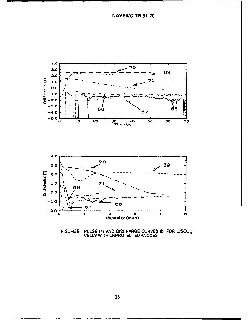
In this experiment, six Li/SOC12 cells were prepared as for the rest of the experi-ments described herein, except that no coating of any kind was placed on the anodes.Table 3 summarizes the results obtained when these cells were removed from storage at70"C after two weeks and discharged at 10 mA/cm2 after they had cooled to room tem-perature. Cells 66 and 70 had OCV values slightly below 3.6V, an indication that thesecells may have undergone some self-discharge during storage. The remaining cells hadOCV values >3.60V. Cells 66 through 68 and Cell 71 did not recover to 2.OV when theinitial pulse was applied. Cells 66 through 68 were driven to potentials more negative than-5.OV, and cell 71 was driven to 0.OV. Cell 69 was driven to a low potential of -1.45V butrecovered to 2.OV after 6.1s, and Cell 70 was driven to 1.18V and recovered to 2.OV after0.15s. This may be a result of a low self-discharge rate which occurred during storage.In any case, the capacity obtained from these cells down to a 2.OV limit was negligible.Cell 69 yielded only 3.3 mAh (0.04 Ah/g-C) and Cell 70 yielded 1.7 mAh (0.03 Ah/g-C).The remaining cells did not have any capacity in this region. Figure 5 shows the pulse (a)
13

NAVSWC TR 91-20
TABLE 2. TEST MATRIX FOR VOLTAGE DELAY DETERMINATION
Days of DischargeExp. Polymer Electrolyte for Number Storage Current DensityNo. Anode Coatings of Cells at 70XC (mA/cm2)
1 None 3 14 10
2 MEEP-(LiX)o 5LiX=LiAICI4 3 14 10LiCF3SO3 3 14 10UPFO 3 14 10UN(CF 3SO 2 3 14 10
3 70 w/o MEEP-30 w/o PEO-(LiX),LiX=LiAICI, 3 14 10LiCF3SO3 3 14 10UPF6 3 14 10LiN(CF 3SO0)2 3 14 10
4 90 w/o MEEP-10 w/o PGDA-(LiX),LiX=LiAICI4 3 14 10LiCF3SO3 3 14 10LiPF6 3 14 10LiN(CF3SO0 2 3 14 10
5 Additional cells based on tests in No. 1, - 14 102, 3, and 4.
TABLE 3. CELL DATA AND RESULTS FOR EXPERIMENT 1
Capacity to aCell Coating Wt. of C OCV Voltage Minimum 2.OV Cutoff CapacityNo. (g) (V) Delay Voltage (mAh) (Ah/g-C)66 None 0.0500 3.26 <-5.0 0.0 0.0
67 None 0.0716 3.60 * <-5.0 0.0 0.0
68 None 0.0575 3.63 * <-5.0 0.0 0.0
69 None 0.0511 3.65 6.1s -1.45 3.3 0.0670 None 0.0647 3.57 0.15s 1.18 1.7 0.0371 None 0.0409 3.66 * 0.05 0.0 0.0
*Did not recover to 2.OV.
14
NAVSWC TR 91-20
4.003.0' -~
1.010 .0
01.
-3.0 :68N6
-4.0 87I~6-5.01
0 10 20 30 40 50 s0 70Time (o)
4.0
3. 69
2.0 , -
.~1.0~ 71068 -_-
S0.0~ _ -...... ......LI
loc-
-1.0~66. -67
-2.00 1 2 3 4
Capacity (mAh)
FIGURE 5. PULSE (a) AND DISCHARGE CURVES (b) FOR U/1SOC12CELLS WITH UNPROTECTED ANODES
15

NAVSWC TR 91-20
and discharge (b) curves for these cells. The capacity was virtually nil even when oneconsiders the discharge down to 0.OV. A further attempt was made to discharge thesecells after they had been allowed to rest -30m. None of them recovered even when thissecond 'discharge' period was extended to 5m.
3.3.2 Exoerment 2: Anodes protected with MEEP-(UX)
Table 4 contains a data summary of the results obtained for the initial pulse of cellsbelonging to Experiment 2 in which the polymer electrolyte coating was prepared by dopingMEEP with one of the four salts. The OCV was >3.66V in each case. The data show theMEEP-UAICI 4 electrolyte to have had the best effect with regard to minimizing the anodepolarization for the initial pulse after storage. Of the three cells having this coating (Nos.42, 43, 44), Cell 42 had the lowest potential (1.15V) upon application of a 10 mA/cm 2
pulse. The delay for this cell was also the least of the entire set shown in the table (0.6s).Cells 43 and 44 had delays of -1.0s duration, and minimum potentials of 1.70 and 1 .1OV,respectively. When the coating consisted of MEEP-UCF 3SO3 , Cells 47,48, and 49 all hadabout the same voltage minimum (1.1V), but varied widely in the delay times. Cell 49 took0.8s to recover, whereas the delay was 2.1 s for cell 48, and 12s for Cell 47. TheMEEP-LiN(CF 3SO2)2 and MEEP-LiPF6 coatings did not perform as well. Two of the threecells having the UN(CF3SO2)2 dopant were driven to slightly negative potentials (-0.05V,and -0.20V), and also varied widely in delay time. Cell 65 recovered after 3.3s, while Cell21 recovered after 7.2m. Cell 62 was driven down to 0.2V, and recovered after 1.6s. Theresults with UPF6 were even more dispersed. Cell 45 was driven down to 0.95V andrecovered after 4.0s, while Cell 46 was driven down to -0.2V and took 49.5 s to recover.The voltage delay curves for these cells are grouped according to the salt used as thedopant, and given in Figures 6 through 9.
3.3.3 Experiment 3: Anodes Protected with (MEEP/PEO)-LiX
When PEO is used as a co-polymer in the anode coating, it significantly increasesthe mechanical strength of the coating. PEO also offers a unique opportunity for visualinspection due to its white color. It is difficult to judge the quality of MEEP coatings dueto the transparent nature of this polymer. The solutions prepared with PEO are noticeablymore viscous than the others used in this program, and the depth of color observed on thesurface of the coated anodes suggested, before the storage experiments began, that threecoats of this electrolyte would be to much to afford anode protection without loss of cellperformance. The data shown in Table 5 were obtained with cells fabricated with anodeshaving three coats of the various composite electrolytes. Cell 56 had an OCV of 3.55V,and may have undergone some self-discharge during storage. The rest of the cells hadOCV values >3.68V. When the cells were pulsed, each was driven below 0.OV. The delaytimes varied from as little as 1.9s for Cell 54, prepared with UAICI4 as the dopant to -46s
16

NAVSWC TR 91-20
TABLE 4. CELL DATA AND PULSE RESULTS FOR EXPERIMENT 2
Wt. of C OCV Voltage Minimum PotentialCell No. Coating (g) (V) Delay (V)
42 MEEP/LAIC1, 0.0568 3.71 0.6s 1.15
43 MEEP/UAIC 4 0.0535 3.70 1.0s 1.70
44 MEEP/UAICI, 0.0527 3.73 0.9s 1.20
47 MEEP/UCF 3SO3 0.0426 3.70 12s 1.10
48 MEEP/ICF3SO3 0.0265 3.66 2.ls 1.10
49 MEEP/UCF 3SO 3 0.0615 3.68 0.8s 1.22
62 MEEP/UN(CF 3SO 2)2 0.0969 3.70 1.6s 0.20
65 MEEP/UN(CF 3SO 2)2 0.0892 3.72 3.3s -0.20
21 MEEP/UN(CF 3SO 2)2 0.0482 3.66 7.2m -0.05
45 MEEP/LiPF6 0.0710 3.68 4.Os 0.9546 MEEP/UPF6 0.0395 3.68 49.5s 0.18
* Cell leaked during storage.Did not recover to 2.OV.Data collection error.
17

NAVSWC TR 91-20
4.0
3.5 43
3.0
44 42
1.0
0.5
0.00 2 4 a a 10 12 14 16 18 20
Time (X)
FIGURE 6. INITIAL PULSE FOR LI/SOCI CELLS WITH MEEP-LiAICI4ANODE COATINGS
4.0
3.5 493.0
E 2.5
2.0
w. 1.5
0.0
-0.5 40. 1
-0.5 48
0.0 2.5 5.0 7.5 10.0 12.5 16.0 17.5 20.0 22.5 25.0Time (a)
FIGURE 7. INITIAL PULSE FOR /SOC CELLS WITH MEEP-UCFrSO3 ANODE COATINGS
18

NAVSWC TR 91-20
4.0
:3.5j
:3.0
2 .5
02 .0
0E .0 2
-0.5
0 2 4 a 8 10 12 14 16 18 20Time (s)
FIGURE 8. INITIAL PULSE FOR LiISOC2 CELLS WITH MEEP-LiN(CF3SO2)2 ANODE COATI NGS
4.0
:3.5
3.0
*:- 2.5
-a 2.0
0
0.0 4-0.5
0.0 2.5 5.0 7.5 10.0 12.5 15.0 17.5 20.0 22.5 25.0Ttme (a)
FIGURE 9. INITIAL PULSE FOR U/50C 2 CELLS WITH MEEP-UIPFIANODE COATINGS
19

NAVSWC TR 91-20
TABLE 5. CELL DATA AND PULSE RESULTS FOR EXPERIMENT 3
Cell Wt. of C OCV Voltage MinimumNo. Coating (g) (V) Delay Potential (V)
Triple Coat
54 (MEEP/PEO)-UAJC 4 0.0492 3.70 1.9s -3.50
64 (MEEP/PEO)-UACI 4 0.0475 3.73 11.6s -8.00
55 (MEEP/PEO)-UCF 3SO3 0.0490 3.71 45.9s -3.65
57 (MEEP/PEO)-UCF 3SO3 0.0391 3.68 12.9s -3.00
59 (MEEP/PEO)-UiCF 3SO3 0.0390 3.68 3.8s -3.2
56 (MEEP/PEO)-LiN(CF 3SO2)2 0.0490 3.55 33.8s -0.60
58 (MEEP/PEO)-LN(CF 3SO2)2 0.0496 3.69 30.Os -3.10
60 (MEEP/PEO)-LiPF 6 0.0451 3.69 * -0.60
63 (MEEP/PEO)-LiPF 6 0.0970 3.68
Single Coat
72 (MEEP/PEO)-LiCF 3SO3 0.0833 3.72
73 (MEEP/PEO)-UCF 3SO3 0.0698 3.68 28s -1.18
76 (MEEP/PEO)-LiN(CF3SO 2)2 0.0799 3.66 4.3s 0.28
77 (MEEP/PEO)-UN(CF 3SO2)2 0.0698 3.70 23s -0.60
78 (MEEP/PEO)-UPF6 00668 3.65 4.5s 0.15
79 (MEEP/PEO)-UPF 6 0.0742 3.70 14s -0.73
• Did not recover to 2.OV•* Data collection error.
See discussion in text.
20

NAVSWC TR 91-20
for Cell 55 prepared with UCF3SO3. Cell 60, prepared with UPF 6 was driven to -0.6V, anddid not recover to 2.OV after nearly three minutes. The corresponding data for Cell 63,also prepared with this salt was lost due to a data collection error. The curves for thesecells are given in Figures 10 through 13.
Cells having single coatings of these polymer electrolytes were stored under thesame conditions and discharged. The coatings studied were those doped with UCF3 SO 3,LiN(CF3SO 2)2, or LiPF 6. All the cells had open circuit potentials >3.65V after storage. Cells72 and 73 had the LiCF 3SO3 dopant (Fig. 14). When the 10 mA/cm2 pulse was applied,the potential of cell 72 dropped immediately to 3.2V, and there was a gradual potentialdecay for the next 7s, before the potential went below 2.OV and reached a low value of1.3V. From this point it took -4s to recover to 2.OV. Cell 73 had a more typical pulsecurve, and the minimum potential was -1.18V, with a delay of 28s. The UN(CF3 SO2 )2
dopant was used in Cells 76 and 77 (Fig. 15). The minimum potential was 0.28V for theformer and -0.6V for the latter. The delay time was 4.3s for Cell 76, and 23s for Cell 77.The coating in Cell 78 was doped with LiPF6 and the minimum potential for the pulse was0.15V, with a delay of 4.5s. The same coating in Cell 79 resulted in a low potential of-0.73V with a 14s delay. Pulse curves for these two cells are shown in Figure 16.
3.3.4 Experiment 4: Anodes Protected with (MEEPIPGDA)-LiX
As the data in Table 6 show, all the cells prepared with PGDA as a co-polymer inthe protective coating had open circuit potentials >3.65V prior to the initial pulse. Cells 27and 29 were prepared with UPF, as the dopant. These cells had the best performance interms of voltage delay mitigation, as the potential of Cell 27 was driven to 1.20V andrecovered to 2.OV after 2.2s, while Cell 29 was not driven below 2.2V. With the exceptionof Cell 33 (MEEP/PGDA)-UAICI[ 4, the other cells were all driven below 2.OV. Recoverytimes for these cells ranged from -11 s for Cell 35 (MEEP/PGDA)-LiN(CF 3SO2 )2 to morethan 6 minutes for Cell 41 (MEEP/PGDA)-LiCF 3SO3. Cell 33 was driven to 0.40V, andrecovered after just over 8s. Figures 17 through 20 show the pulse data for cells with theLiAICI4, UCF 3SO3, LiN(CF3SO2)2, and liPF6 doped coatings, respectively.
3.4 DISCHARGE CAPACITY
Capacity of stored cells is also an important consideration. With this in mind, wehave found it of interest to compare the capacity obtained from U/SOC 2 cells which havebeen stored at 70"C for 14 days. The following data were all obtained by resuming the 60mA (10 mA/cm2) discharge current after following the initial pulse by a brief rest period.The capacities indicated in the tables are for two voltage ranges: OCV to 2.OV, and OCVto 0.OV. In each case the capacity has been normalized by dividing the number of mAhobtained by the weight of carbon in the cathode.
21

NAVSWC TR 91-20
4.0
3.0
2.0
~*1.0
01.
-~3.0-4.0 64
0.0 2.5 5.0 7.5 10.0 12.5 15.0 17.5 20.0 22.5 25.0Time (an)
FIGURE 10. INITIAL PULSE FOR LI/S0C 2 CELLS WITH (MEEP/PEO)-UIAIC4 ANODE COATINGS
3.0 5
3.0
1.0
-3.0
0.0 5.0 10.0 15.0 20.0 25.0 30.0 35.0 40.0 45.0 50.0Time (o)
FIGURE'11. INITIAL PULSE FOR LI/SOCI CELLS WIT ME/O)UICF 3SO3 ANODE COATING9 h(EE/E)
22

NAVSWC TR 91-20
3.0
2.0 5
.~0.0
-3.0
0.0 4.0 8.0 12.0 16.0 20.0 24.0 28.0 32.0 38.0 40.0Time (in)
FIGURE 12. INITIAL PULSE FOR LI/SOC 2 CELLS WITH (MEEP/PEO)-LJN(CF3SO 2 ANODE COATINGS
3.0
2.0
~1.0*0.0
-1.
-2.0
-3.0
0.0 4.0 8.0 12.0 16.0 20.0 24.0 28.0 32.0 36.0 40.0Time (an)
THE ANODE COATING WAS (MEP/PE0)-LiPF4
FIGURE 13. INITAL PULSE FOR CELL 60
23

NAVSWC TR 91-20
3.53.0
-~2.5 7
2.0 - - - - - - - - -
2.01.0 73
01.0-~0.5-
-1.6
0 5 10 15 20 25 30 35 40Time (a)
FIGURE 14. INITIAL PULSE FOR U/SOCI CELLS IN WHICH ASINGLE COAT OF (MEEP/PgO)-LICF3SO3 WAS USEDFOR ANODE PROTECTION
4.03.53.0 782.52.0- - - - - - - - - -
~1.5 7*1.0~0.5
-1.0-1.5
0 6 10 15 20 26 30 35 40Time (s)
FIGURE 15. INITIAL PULSE FOR LI/SOCI CELLS IN WHICH ASINGLE COAT OF (MEEP/PO)-LiN(CFS0 2)2 WASUSED FOR ANODE PROTECTION
24

NAVSWC TR 91-20
4.0
3.5:3.0
72.5
.- 2.0
~1.5 7w1.0~0.5
-1.5
-200 5 10 15 20 25Time (o)
FIGURE 16. INITIAL PULSE FOR Li/SOCI CELLS IN WHICH A SINGLECOAT OF (MEEP/PEO)-UP9* WAS USED FOR ANODEPROTECTION
TABLE 6. CELL DATA AND PULSE RESULTS FOR EXPERIMENT 4
Cell Coating Wt. of C OCV Voltage MinimumNo. ____________ (g) (V) Delay Potential (V)
31 (MEEP/PGDA)-LiAICI, 0.0459 3.63 14.6S -0.1033 (MEEP/PGDA)-LiAIC 4 0.0486 3.65 8.4s 0.40
39 (MEEP/PGDA)-LiCF 3SO3 0.0542 3.71 38.8s -0.7340 (MEEP/PGDA)-LiCF3SO3 0.0461 3.73 158s -1.48
41 (MEEP/PGDA)-UCF3S0 3 0.0571 3.73 6.3m -3.05
34 (MEEP/PGDA)-LiN(CF 3SO2)2 0.0446 3.70 17.2s -0.45
35 (MEEP/PGDA)-LiN(CF 3S02)2 0.0487 3.70 10.8s -0.09
38 (MEEP/PGDA)-LiN(CF350 2)2 0.0483 3.72 31 .Os -0.40
27 (MEEP/PGDA)-LiPFe 0.0496 3.68 2.15s 1.20
29 (MEEP/PGDA)-LiPFs 0.0482 3.67 -2.18
25

NAVSWC TR 91-20
3.5
3.0 3
2.0
Js1.50
0.1.0 3
0.0
-0.5
0.0 2.0 4.0 6.0 8.0 10.0 12.0 14.0 16.0 18.0 20.0Time (w)
FIGURE 17. INITIAL PULSE FOR U/SOCL CELLS WITH(MEEP/PGDA)-LiAIC4 ANODE COATINGS
4.0. . . . . . . . .
3.2 32.4
0.8 *
0.0 ii 41I
-3.2
-4.0 .
0.0 16.0 32.0 48.0 64.0 80.0 98.0 112.0 128.0 144.0 160.0Time (a)
FIGURE 18. INITIAL PULSE FOR U/S0C CELLS WITH(MEEP/PGDA)-LiCF38O 3 ANODE COATINGS
26

NAVSWC TR 91-20
3.03.353.0
2.5 32.0
CL 1.0 ',0.5
0.0 /'
-0.5-1.0 . .
0.0 4.0 8.0 12.0 16.0 20.0 24.0 28.0 32.0 38.0 40.0Time (a)
FIGURE 19. INITIAL PULSE FOR LI/SOCI2 CELLS WITH(MEEP/PGDA)-LiN(CFSO0 2 ANODE COATINGS
4.0
3.5
.0 27
2.5 .. ..
29
A00-1.5
1.0
0.5
0.0 0.0 5.0 10.0 18.0 20.0Time (a)
FIGURE 20. INITIAL PULSE FOR Li/SOCI6 CELLS WITH(MEEP/PGDA)-LiPF. ANODE COATINGS
27
NAVSWC TR 91-20
3.4.1 Experiment 1: Uncoated Anodes
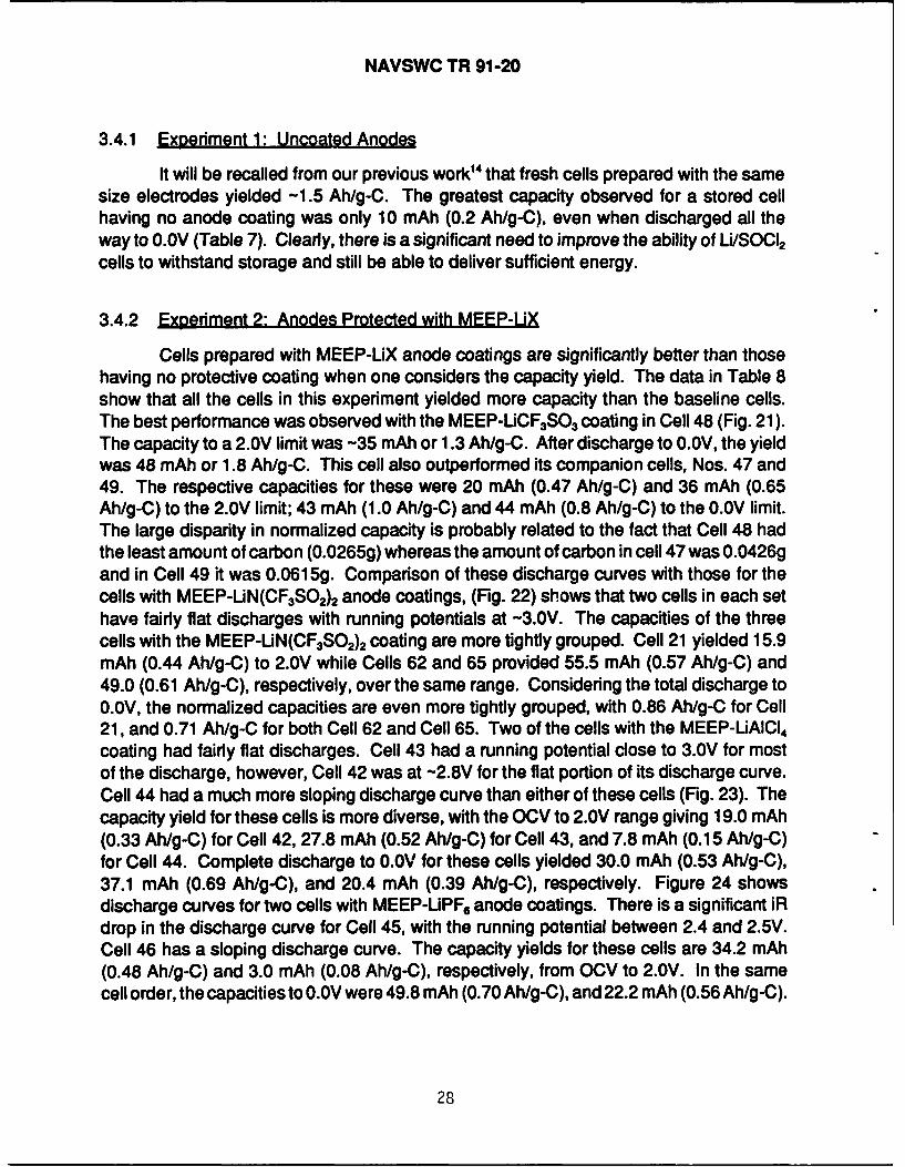
It will be recalled from our previous work' 4 that fresh cells prepared with the samesize electrodes yielded -1.5 Ah/g-C. The greatest capacity observed for a stored cellhaving no anode coating was only 10 mAh (0.2 Ah/g-C). even when discharged all theway to O.OV (Table 7). Clearly, there is a significant need to improve the ability of Li/SOC 2
cells to withstand storage and still be able to deliver sufficient energy.
3.4.2 Experiment 2: Anodes Protected with MEEP-UX
Cells prepared with MEEP-LiX anode coatings are significantly better than thosehaving no protective coating when one considers the capacity yield. The data in Table 8show that all the cells in this experiment yielded more capacity than the baseline cells.The best performance was observed with the MEEP-UCF 3SO3 coating in Cell 48 (Fig. 21).The capacity to a 2.0V limit was -35 mAh or 1.3 Ah/g-C. After discharge to 0.OV, the yieldwas 48 mAh or 1.8 Ah/g-C. This cell also outperformed its companion cells, Nos. 47 and49. The respective capacities for these were 20 mAh (0.47 Ah/g-C) and 36 mAh (0.65Ah/g-C) to the 2.OV limit; 43 mAh (1.0 Ah/g-C) and 44 mAh (0.8 Ah/g-C) to the 0.OV limit.The large disparity in normalized capacity is probably related to the fact that Cell 48 hadthe least amount of carbon (0.0265g) whereas the amount of carbon in cell 47 was 0.0426gand in Cell 49 it was 0.0615g. Comparison of these discharge curves with those for thecells with MEEP-LiN(CF3SO2)2 anode coatings, (Fig. 22) shows that two cells in each sethave fairly flat discharges with running potentials at -3.OV. The capacities of the threecells with the MEEP-UN(CF 3 SO2 )2 coating are more tightly grouped. Cell 21 yielded 15.9mAh (0.44 Ah/g-C) to 2.OV while Cells 62 and 65 provided 55.5 mAh (0.57 Ah/g-C) and49.0 (0.61 Ah/g-C), respectively, over the same range. Considering the total discharge to0.OV, the normalized capacities are even more tightly grouped, with 0.86 Ah/g-C for Cell21, and 0.71 Ah/g-C for both Cell 62 and Cell 65. Two of the cells with the MEEP-LiAICI 4
coating had fairly flat discharges. Cell 43 had a running potential close to 3.OV for mostof the discharge, however, Cell 42 was at -2.8V for the flat portion of its discharge curve.Cell 44 had a much more sloping discharge curve than either of these cells (Fig. 23). Thecapacity yield for these cells is more diverse, with the OCV to 2.OV range giving 19.0 mAh(0.33 Ah/g-C) for Cell 42, 27.8 mAh (0.52 Ah/g-C) for Cell 43, and 7.8 mAh (0.15 Ah/g-C)for Cell 44. Complete discharge to 0.OV for these cells yielded 30.0 mAh (0.53 Ah/g-C),37.1 mAh (0.69 Ah/g-C), and 20.4 mAh (0.39 Ah/g-C), respectively. Figure 24 showsdischarge curves for two cells with MEEP-UPF 6 anode coatings. There is a significant iRdrop in the discharge curve for Cell 45, with the running potential between 2.4 and 2.5V.Cell 46 has a sloping discharge curve. The capacity yields for these cells are 34.2 mAh(0.48 Ah/g-C) and 3.0 mAh (0.08 Ah/g-C), respectively, from OCV to 2.OV. In the samecell order, the capacities to 0.OV were 49.8 mAh (0.70 Ah/g-C), and 22.2 mAh (0.56 Ah/g-C).
28

NAVSWC TR 91-20
TABLE 7. COMPARISON OF CELL CAPACITIES FOR EXPERIMENT 1
To 2.OVTo O.OV
Cell No. Coating mAh Ah/g-C mAh Ahfg-C
6Noe0.0 0.0 0.0 0.0
6Noe0.0 0.0 0.0 0.0
6Noe0.0 0.0 0.0 0.0
6Noe3.3 0.06 10.1 0.20
7Noe1.7 0.03 3.6 0.06
7Noe0.0 0.0 0.0 0.0
TABLE 8. COMPARISON OF CELL CAPACITIES FOR EXPERIMENT 2
To 2.OV To O.OV
Cell No. Coating mAh Ah/g-C mAh Ah/g-C
42 MEEP-LiAIC 4 19.0 0.33 30.0 0.53
43 MEEP-LIAIC 4 27.8 0.52 37.1 0.69
44 MEEP-LiAIC 4 7.8 0.15 20.4 0.39
47 MEEP-LiCF 3SO3 20.0 0.47 43.4 1.02
48 MEEP-LiCF 3S03 35.2 1.34 47.9 1.81
49 MEEP-LiCF 3SO3 35.9 0.65 44.1 0.80
21 MEEP-LiN(CF 3S02)2 15.9 0.44 30.9 0.86
62 MEEP-LiN(CF 3S02)2 55.5 0.57 68.4 0.71
65 MEEP-UN(CF 3S02)2 49.0 0.61 57.3 0.71
45 MEEP-UPF 6, 34.2 0.48 49.8 0.70
46MEEP-UPF6 3.0 0.08 22.2 0.,56
29

NAVSWC TR 91-20
3.0 ~ --- -
*-2.0
~1.0
S0.0
-1.0
-2.00 10 20 30 40 50 s0
Capacity (mAh)
FIGURE 21. DISCHARGE CURVES FOR Li/SOCI2 CELLS WITHMEEP-uCF 3SO3 ANODE COATINGS
4 .0 .
1.0 6
20
-1.0
0 10 20 30 40 50 60 70Capacity (mAh)
FIGURE 22. DISCHARGE CURVES FOR U/S001 2 CELLS WITHMEEP-UN(CF3SO 2)2 ANODE COATINGS
30

NAVSWC TR 91-20
4.0
3.0----------------
-2.0 -
2.01N--,.
0.0~0044 42 4
-1.0
-2.0 . . . . . .0o 10 15 20 25 30 35 40
Capacity (xnAh)
FIGURE 23. DISCHARGE CURVES FOR U/SOC 2 CELLS WITHMEEP-LiAICI, ANODE COATINGS
3.0
21.0
0.
4. 450o.0
-1.0
-2.00 10 20 30 40 50 60
Capacity (nA)
FIGURE 24. DISCHARGE CURVES FOR U/S001 2 CELLS WITHMEEP-bPFe ANODE COATINGS
31

NAVSWC TR 91-20
3.4.3 Exoeriment 3: Anodes Protected with (MEEP/PEO)-LiX
Figures 25 through 28 show the discharge curves for cells prepared with threecoats of (MEEP/PEO)-UX electrolytes in which the dopant was UAJCI4 , UCF3 SO 3,LiN(CF3SO2)2, and UPF., respectively. All the curves show a significant voltage delayeven though these cells were previously pulsed. One of the cells (No. 64) with the UAICI4dopant, and one (No. 59) with the UCF3SO dopant were driven below 0.OV. We believethat the conductivity of the protective film is not high enough to allow such a thick coating.The iR drop induced by the coatings limits the capacity between OCV and 2.OV to a rangeof 0.6 mAh (0.01 Ah/g-C) to 11.4 mAh (0.23 Ah/g-C). The cells did have more capacityto provide at lower potentials, however, as the data in Table 9 show. We cannot explain,however, why most of the cells with identical coatings have such a spread in the normalizedcapacities. For example, Cells 54 and 64 have capacities of 0.44 and 0.52 Ah/g-C,respectively, however, Cells 55, 57, and 58, with MEEP/PEO-UCFSO 3, have capacitiesof 0.63, 0.68, and 0.84 Ah/g-C. The difference is even greater for the cells withUN(CF 3SO2)2 and LiPF6 doped coatings. Normalized capacities obtained with the formerare 0.70 Ah/g-C (Cell 56) and 0.48 Ah/g-C (Cell 58) while for the latter, Cell 60 yielded0.25 Ah/g-C, and Cell 63 yielded 0.53 Ah/g-C.
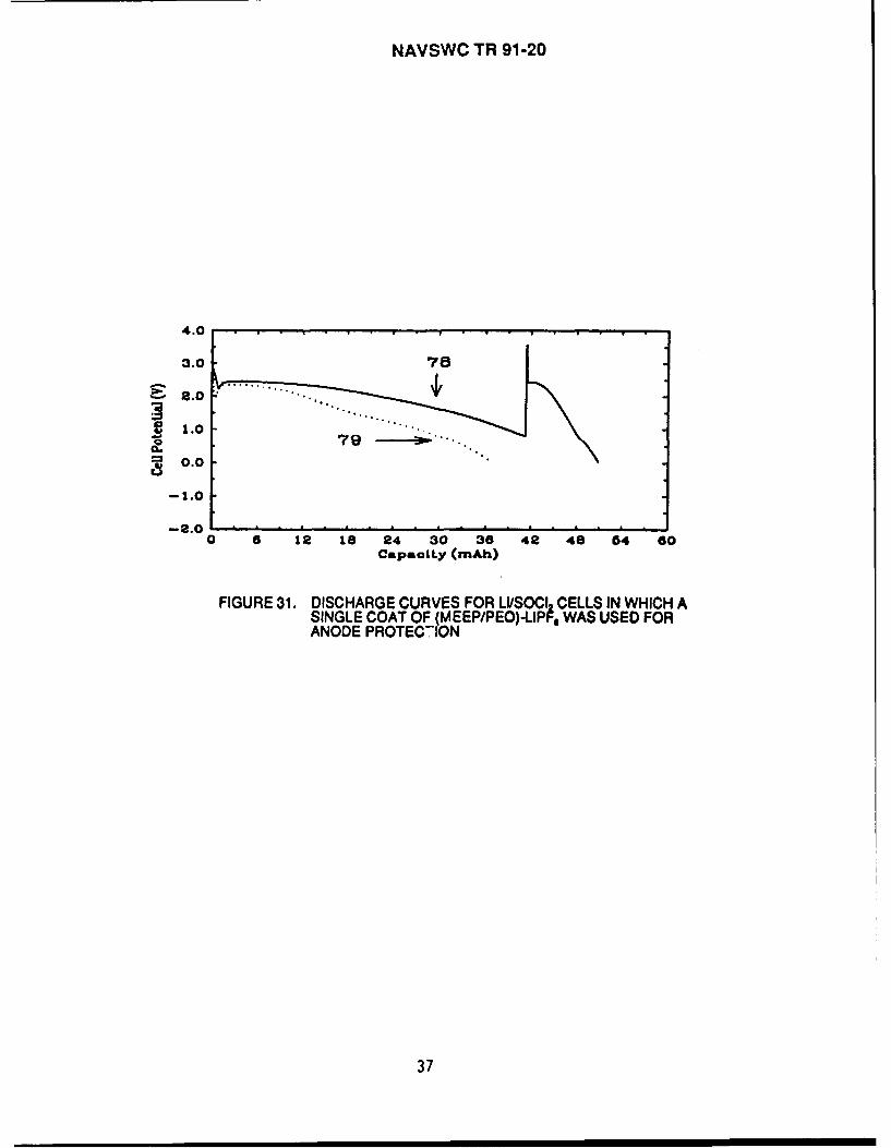
Cells having anodes coated once with either the UCF 3SO3, UN(CF 3SO2 )2 , or LiPF6doped film were also discharged. Cells 72 and 73 (Fig. 29), having the (MEEP/PEO)-UCF3SO3 film had similar capacities over both potential ranges. For Cell 72, the capacitywas 16.5 mAh to 2.OV while it was 14.9 mAh for Cell 73. The normalized capacity for thesame range was -0.2 Ah/g-C for both cells. Similarly, discharge to 0.OV resulted in acapacity of 45 mAh (0.54 Ah/g-C) for Cell 72, and -41 mAh (0.58 Ah/g-C) for Cell 73.When the film was doped with UN(CF3 SO2 )2 (Fig. 30), the results were more scattered;Cell 76 had a generally higher running potential (-2.8-2.9V) for most of its discharge. The2.OV capacity was -47 mAh (0.59 Ah/g-C) for Cell 76, and 16.2 mAh (0.23 Ah/g-C) for Cell77. The difference was less pronounced when discharge to the 0.OV limit was complete,as the capacity was -58 mAh (0.73 Ah/g-C) for Cell 76, and -43 mAh (0.62 Ah/g-C) forCell 77. Cells 78 and 79, contained the (MEEP-PEO)-UPF 6 film, and both had rathersloping discharge curves. We found that by stopping the discharge at -0.8V, and allowingthe cell a rest period of -30m, the OCV recovered to 3.55V, and an additional 4 mAhcapacity above 2.OV was obtained. The two discharge curves have been spliced togetherin Figure 31, and show that the capacity to 0.8V for the first (uninterrupted) discharge is40.8 mAh (0.61 Ah/g-C), and that the second discharge after the rest period adds 9.6 mAhfor a total capacity of 50.7 mAh or 0.76 Ah/g-C.
3.4.4 Experiment 4: Anodes Protected with (MEEP/PGDA)-LiX
Photo-polymerized PGDA provided avery effective way to improve the dimensionalstability of the protective polymer films. As with the cells having MEEP/PEO-LiX coatings,
32

NAVSWC TR 91-20
3.0
1.0
0 4 8 12 is 20 24 28 32 38 40Capacity (MAli)
FIGURE 25. DISCHARGE CURVES FOR U/SOCd2 CELLS WITH(MEEP/PEO)*UJC 4 ANODE COATINGS
4.0
3.0
55-1.0
-2.00 4 8 12 16 20 24 28 32 36 40
Capacity (mnAh)
FIGURE 26. DISCHARGE CURVES FOR U/SOCI CELLS WITH(MEEP/PEO)-UCF 3SO3 ANODE COATIN&iS
33

NAVSWC TR 91-20
3.0
2.
30.0
-1.0
0 4 8 12 16 20 24 28 32 36 40Capacity (mnAh)
FIGURE 27. DISCHARGE CURVES FOR Ui/SOCI CELLS WITH(MEEP/PEO)LiN(CFSO 2)2 ANODE COAiNGS
4.0 . . . . . . v v . . . I
3.0
~- 2.0 -
0.
30.0 60 8
-1.0
-2.0 A
0 3 6 9 12 15 18 21 24 27 30Capacity (rnAh)
FIGURE 28. DISCHARGE CURVES FOR UI/S001 2 CELLS WITH(MEEP/PEO)-UIPFe ANODE COATINGS
34

NAVSWC TR 91-20
TABLE 9. COMPARISON OF CELL CAPACITIES FOR EXPERIMENT 3
j To 2.OV To O.0V
Cell No. Coating mAh Ah/g-C jmAh Ah/g-C______ _________________Triple Coat _______ ___
54 (ME EP/PEO)-LiAIC14 11.4 0.23 21.6 0.44
64 (MEEP/PEO)-LiAICI 4 7.8 0.16 24.5 0.52
55 (MEEP/PEO)-LiCF 3SO3 0.6 0.01 31.0 0.63
57 (MEEP/PEO)-LiCF 3SO3 7.2 0.18 26.7 0.68
59 (MEEP/PEO)-LiCF 3SO3 2.7 0.07 32.7 0.84
56 (MEEP/PEO)-LiN(CF 3S02)2 5.5 0.11 34.1 0.70
58 (MEEP/PEO)-LiN(CF 3S02)2 6.0 0.12 24.0 0.48
60 (ME EP/PEO)-LiPF 6 0.6 0.01 11.1 0.25
63 (MEEP/PEO)-LiPF 6 7.2 0.16 24.3 0.53______ ~~~~Single Coal _ _ _ __ _ _ _ _
72 (MEEP/PEO)-LiCF 3SO3 16.5 0.20 45.0 0.54
73 (MEEP/PEO)-LiCF 3SO3 14.9 0.21 40.8 0.58
76 (MEEP/PEO)-LiN(CF 3S02)2 46.8 0.59 58.2 0.73
77 (MEEP/PEO)-LiN(CF 3S02)2 16.2 0.23 43.2 0.62
78 (ME EP/PEO)-LiPF6 21.6 0.32 - -
79 (MEEP/PEO)-LiPF 6 111.4 10.15 136.9 0.50
35

NAVSWC TR 91-20
4.0
3.0 72
-~2.0
a) 1.073 Blo
~0.01
-1.0
-2.00 12 24 36 48 60
Capacity (rnAh)
FIGURE 29. DISCHARGE CURVES FOR LUSOCI2 CELLS IN WHICH ASINGLE COAT OF (M EEP/PEO)-UCF 3SO3 WAS USED FORANODE PROTECTION
4.0 . . .
3.0
-~2.0
~1.0
0.0
-1.0
0 6 12 18 24 30 36 42 48 54 60Capacity (mnAh)
FIGURE 30. DISCHARGE CURVES FOR UI/5001 CELLS IN WHICH ASINGLE COAT OF4(MEEP/PEO)-LIN(CF 3502)2 WAS USEDFOR ANODE PROTECTION
36
NAVSWC TR 91-20
43.0
13.0
-1.0
-0 6 12 i8 24 30 38 42 48 54 80Capacly (mAh)
FIGURE 31. DISCHARGE CURVES FOR LVSOCI CELLS IN WHICH ASINGLE COAT OF (MEEP/PEO).LiP0* WAS; USED FORANODE PROTEC-ION
37

NAVSWC TR 91-20
all the cells showed some iR drop when discharge was resumed at 10 mA/cm 2. Unlikethe cells with PEO containing coatings, none of the cell potentials was driven below 0.OV.Capacities obtained with these coatings are summarized in Table 10. When dischargewas resumed, Cell 41, having anodes doped with UCF3SO3 was pushed to -1 .4V, and therest of the cells never had their running potential drop below 1.9V. With respect to con-sistency, Cells 31 and 33, having the UAICI4 doped coating yielded 24.6 mAh (0.54 Ah/g-C)and 24.3 mAh (0.50 Ah/g-C), respectively, between OCV and 2.OV. Discharge to 0.OVgave a final capacity of 29.4 mAh for both cells, a normalized value of 0.64 Ah/g-C for Cell31, and 0.60 Ah/g-C for Cell 33. Both discharges plateaued at -2.9V (Fig. 32). The coatingwith UN(CF3SO2)2 yielded the highest normalized capacities, and was the next best interms of consistency. Cell 34 through 36 provided respective OCV to 2.OV capacities of34.2 mAh (0.77 Ah/g-C); 33.6 mAh (0.69 Ah/g-C); and 33.5 mAh (0.69 Ah/g-C). Thecapacities to 0.OV, in the same order, were 46.1 mAh (1.0 Ah/g-C), 41.6 mAh (0.85 Ah/g-C),and 42.6 mAh (0.88 Ah/g-C). Figure 33 shows the discharge curves to be gently slopingwith mid-discharge potentials of -2.8V. Two of the cells with LiCF 3SO3 as the dopant (Nos.40 and 41) had very little capacity above 2.OV (Fig. 34). Cell 39, however, gave 33.0 mAhor 0.61 Ah/g-C between OCV and 2.OV. The capacities to 0.OV were 48.1 mAh (0.89Ah/g-C) for Cell 39, and 27.0 mAh for each of the others. The normalized capacities forCell 40 was 0.59 Ah/g-C, for cell 41 it was 0.47 Ah/g-C. Figure 35 shows a severe differencein cell performance for two cells having anode coatings doped with LiPF 6. Cell 29 had anearly flat discharge curve at -3.OV, while Cell 27 had a small plateau region near -2.5V,and a majority of the discharge curve was severely sloped. The capacities vary widelyalso. Cell 27 yielded 46.1 mAh (0.93 Ah/g-C) to 2.OV, and 54.1 mAh (1.1 Ah/g-C) to 0.OV.For the same ranges, the capacities for Cell 29 were 19.2 mAh (0.40 Ah/g-C), and 36.6mAh (0.76 Ah/g-C).
3.5 AACELLS
AA Cells are being prepared in which the anode coatings are MEEP-(UAIC 4),MEEP-(UCF 3SO3), (MEEP/PGDA)-(LiPF 6), and (MEEP/PEO)-UPF 6. Results for testsperformed with these cells will be available for the Phase II proposal.
38

NAVSWC TR 91-20
TABLE 10. COMPARISON OF CELL CAPACITIES FOR EXPERIMENT 4
To 2.OV To O.OV
Cell No. Coating mAh Ah/g-C mAh Ah/g-C
31 (MEEP/PGDA)-LiAIC 4 24.6 0.54 29.4 0.64
33 (MEEP/PGDA)-LiAIC 4 24.3 0.50 29.4 0.60
39 (MEEP/PGDA) -LiCF3SO3 33.0 0.61 48.1 0.89
40 (MEEP/PGDA)-LiCF 3SO 3 5.7 0.12 27.0 0.59
41 (MEEP/PGDA)-LiCF 3SO 3 4.2 0.07 27.0 0.47
34 (MEEP/PGDA)-LiN(CF 3SO2)2 34.2 0.77 46.1 1.03
35 (MEEP/PGDA)-LiN(CF 3SO2)2 33.6 0.69 41.6 0.85
36 (MEEP/PGDA)-LiN(CF 3S0 2)2 33.5 0.69 42.6 0.88
27 (MEEP/PGDA)-LiPF 6 46.08 0.93 54.06 1.09
29 (MEEP/PGDA)-LiPF 6 19.2 0.40 36.6 0.76
39

NAVSWC TR 91-20
3.0
*'2.0
~1.0a3
~0.0
-1.0
0 3 8 9 12 15 1s 21 24 2? 30Capacity (mAh)
FIGURE 32. DISCHARGE CURVES FOR Li/SOC6 CELLS WITH(MEEP/PGDA)-UAIC 4 ANODE COATINGS
3.0
2.0 34
~1.0
0o.0
-1.0 3
0 5 10 15 20 25 30 35 40 45 50Capacity (inAh)
FIGURE 33. DISCHARGE CURVES FOR U/SOC 2 CELLS WITH(MEEP/PGDA)-UN(CFSO~J2 ANODE COATINGS
404

NAVSWC TR 91-20
3.0
1.0 3000
0.0
41-1.0
0 5 10 15 20 25 30 35 40 45 50Capacity (mAh)
FIGURE 34. DISCHARGE CURVES FOR UI/SOC!2 CELLS WITH(MEEP/PGDA)-LiCF3SO 3 ANODE COATINGS
3.0
-2.0
~1.0
0.0
-1.0
-2.0 . . . . . . . . . . . .0 8 12 18 24 30 36 42 48 (84 80
Capacity (mAh)
FIGURE 35. DISCHARGE CURVES FOR U/SOC6. CELLS WITH(MEEP/PGDA)-LIPFe ANODE COATNGS
41

NAVSWC TR 91-20
CHAPTER 4
SUMMARY AND CONCLUSIONS
The results obtained from this program demonstrate clearly that there is anadvantage to using U ion-conductive polymers as anode overlayer protection for Li/SOC12cells. Cells having no such anode protection usually do not recover to 2.OV, and exhibitlittle or no capacity after storage for two weeks at 70"C. Cells prepared in an identicalfashion but differing in that the anodes were coated with one of several UX-doped films(where UX was UAICI4, UCF 3SO 3, LiN(CF 3SO0)2, or UPF6) were discharged after storagewith varying degrees of success.
Among the salts used as dopants, none can yet be ruled out. For example, whenMEEP was the only polymer used in the protective film, the minimum delay (0.6 to 1.0s)was obtained with LiAICI4, and the potential was not driven below -1.2V. Minimumpotentials of -1V were also obtained when the salt was either UCF3SO3 or LiPF6. For theexperiment conducted with a MEEP/PGDA composite, only the one coating doped withLiPF6 allowed the cell to maintain a potential 1.2V or greater during the initial pulse. Withregard to capacity, the overall largest yield was -1.8Ah/g-C forCell 48, in which the coatingwas MEEP-UCF 3SO 3. Other cells No. 47: (MEEP/UCF 3SO3); No. 34: (MEEP/PGDA)-LiN(CF 3SO2)2; and No. 27 (MEEP/PGDA)-LiPF 6 had total capacities near 1.0 Ah/g-C. Withrespect to the voltage delay, the results obtained with (MEEP/PEO)-UX coatings were notsatisfactory; however, 5 of the 9 cells tested yielded capacities in the range of 0.5 to 0.8Ah/g-C. The highest capacity was obtained when the salt was LiCF3SO3. The next bestcapacity for a coating made with PEO was observed in Cell 58, in which LiN(CF3S0 2)2 wasthe dopant and the capacity was 0.70 Ah/g-C.
It is difficult to select one or two 'best' coatings or dopant salts because of the widevariability of performance for cells having the same coating. It appears that the singlelargest factor affecting the reproducibility is the uniformity of the coating itself. Use of thePEO containing composite provided visual evidence of irregular polymer coating thick-nesses on the anode surface, an indication which was not available when transparentMEEP was the only polymer used. A major emphasis in Phase II should be developmentof a method to uniformly and reproducibly coat the anode surface with polymer electrolytefilms.
42

NAVSWC TR 91-20
REFERENCES
1. C. R. Schlaikjer, "Lithium-Oxyhalide Cells," Chapter 12 in ithium Batteries, J. P.Gabano, ed., Academic Press, NY (1983).
2. J. R. Driscoll, et al., "Lithium Inorganic Electrolyte Batteries," EIC Laboratories, Inc.,Final Report, ECOM-74-0030-F, March 1978.
3. A. N. Dey, "Primary Li/SOC12 Cells, X. Optimization of D-Cells with Respect to EnergyDensity Stability and Safety,* J. Power Sources, §, 57 (1980).
4. C. R. Schlaikjer, "Thionyl Chloride Electrolytes Containing B1oC11& and B12CI12","Proc. 281h Power Sources Symposium, Atlantic City, NJ, June (1978).
5. W. L. Bowden, J. S. Miller, D. Cubbison, and A. N. Dey, in Lim Batteries, ed. A.N. Dey, "New Electrolyte Salts for Li/SOCI2 Cells," The Electrochemical Society,PV-84-1, 80 (1984).
6. N. A. Fleischer, S. M. Manske, and R. J. Ekern, "Reduction of Voltage Delay inLi/SOC 2 System," ibid.
7. K. M. Abraham, U.S. Patent 4,362,794 (1982).
8. J. P. Gabano, and P. Lenfant, "Lithium Thionyl Chloride Cells: Present Status andPerformance," Electrochemical Society Fail Meeting, Pittsburgh, PA, October 15-20,1978, The Electrochemical Society, Princeton, NJ, Abstract No. 27.
9. D. L. Chua, W. C. Merz and W. S. Bishop,"Lithium Passivation in the Thionyl ChlorideSystem," Proc. 27 th Power Sources Conf., 33, (1976).
10. D. Vallin, "A New Inorganic Additive for Voltage Delay Alleviation in Li/SOC 2 Cells,"Proc. 32"3 Power Sources Symposium, Cherry Hill, NJ (1986).
11. J. W. Boyd, "The Effect of Polyvinyl Chloride and Fe on Film Growth and VoltageDelay in SOC12 Electrolytes," J. Electrochem. Soc., j34, 18 (1987).
12. N. A. Fleischer and R. J. Ekern, "Reduction of Voltage delay in Li/SOC 2 Cells," J.Power Sources, 1Q, 1979 (1983).
13. D. S. Rajoria and J. P. de Neufville, "Improved Coatings for Lithium Anodes," 32wInternational Power Sources Symposium, Cherry Hill, NJ (1986), p.488.
14. K. M. Abraham, D. M. Pasquariello, and M. Alamgir, "Research to Alleviate VoltageDelay in Li/SOCI Cells," Final Report on NSWC Contract N60921-88-C-0102,November 1989.
43

NAVSWC TR 91-20
15. K. M. Abraham, D. M. Pasquariello, and G. Dakwa, "Lithium Ion Conductive PolymerElectrolyte Films to Alleviate Voltage Delay in U/SOCI2 Cells," Final Report, July,1990.
16. H. R. Allcock, P. E. Austin, T. X. Neenan, J. T. Sisko, P. M. Blonsky, and D. F.Shriver, "Polyphosphazenes with Etheric Side Groups: Prospective Biomedical andSolid Electrolyte Polymers," Macromolecules, j2, 1508 (1986).
44

NAVSWC TR 91-20
DISTRIBUTION
Copies Copies
Commander Office of The Chief of NavalNaval Sea Systems Command Research
PMS415G (B Kriese) 1 Attn:SEA66521 (H. Holter) 1 ONR Code 1113ES (R. Nowak)PMS393 1 ONT Code 23
Washington, D.C. 20362-5101 (A.J. Faulstich) 1ONT Code 232 (D. Houser) 1
Commander ONT Code 235 (W. Ching) 1Maval Ocean Systems Center 800 N. Quincy StreetAttn: Code 634 (S. Szpak) 1 Arlington, VA 22217-5000
Code 634 (P. Boss) 1Code 633 (L. Johnson) 1 Commander
San Diego, CA 92512-5000 Naval Air Development CenterAttn: Library
Commander Warminster, PA 18974Naval Weapons Support CenterAttn: Code 305 (J. Gucinski) 1 Naval Technical IntelligenceCrane, IN 47522-5030 Center
Attn: LibraryCommander 4301 Suitland RoadSpace and Naval Warfare Systems Washington, D.C. 20390Command
Attn: SPAWAR OOF (A. Sliwa) 1 HeadquartersWashington, D.C. 20363-5100 U.S. Army Corps of Engineers
Attn: Dr. Robert B. Oswald 1Commander 20 Massachusetts Ave. NW.Naval Underwater Systems Center Washington, D.C. 20314-1000Attn: Code 804 (S. Tucker) 1Newport, RI 02841-5047 NASA Goddard Space Flight
CenterCommander Space Power ApplicationsNaval Weapons Center Branch, Code 711Attn: Code 3853 (M. Miles) 1 Greenbelt RoadChina Lake, CA 93555 Greenbelt, MD 20771
Commander Science ApplicationsNaval Coastal Systems Center International Corp.Attn: Code 4210 (M. Bradshaw) 1 Attn: Dr. Robert B. Davidson
Code 4220 (G. Hesoun) 1 1710 Goodridge DriveCode 5320 (T. English) 1 McLean, VA 22102
Panama City, FL 32407-5000Alliant Techsystems
Central Intelligence Agency Attn: D. Chuac/o OTS (Tyler X. Mahy) 1 104 Rock RoadWashington, D.C. 20505 Horsham, PA 19044
(1)

NAVSWC TR 91-20
DISTRIBUTION (CONT'D)
Copies Copies
Naval Electronics Systems Defense Technical InformationSecurity Center Center
Attn: D. Guerrino 1 Cameron Station 13801 Nebraska Ave. Alexandria, VA 22304-6145Washington, D.C. 20390-5270
Library of CongressCommander Attn: CRS-ENR (A. Abell) 1Naval Ordnance Station CRS-SPR (F. Sissine) 1Attn: -Dr. Mae I. Fauth 1 Washington, D.C. 20540Bldg. 600, Code 4520NIndian Head, Md 20640 NASA Goddard Space Flight Center
Attn: Code 711 1Norfolk Naval Base Greenbelt, MD 20771Defense Reutilization MarketingOffice 1 NASA Johnson Space Center
P.O. Box 15068 Attn: Code EP5 (B.J. Bragg) 1Norfolk, VA 23511-0068 NASA Road 1
Houston, TX 77058Center for Naval Analyses4401 Fort Avenue 1 NASA LangleyP.O. Box 16268 Attn: MS 433 (.. Gowdey) 1Alexandria, VA 22302-0268 Hampton, VA 23665
Mare Island Naval Shipboard Headquarters,Attn: Code 280.08, Stop 060 Department of Transportation
R. Houlter 1 U.S. Coast Guard CivilVallejo, CA 94590-5100 Engineering Division 1
Attn: G-ECV-3David Taylor Research Center Washington, D.C. 20593
Annapolis LaboratoryAttn: Code 272T H. Urbach 1 NOAA Data Buoy Center
Code 2752 R. Bloomquist 1 Attn: D. Scalley, Code WDB2 1Annapolis, MD 21401 NSTL Station, MS 39529
Commander Sandia National LaboratoriesU.S. Army LABCOM SLCET-P Attn: S.C. Levy, Div. 2523 1Akttn: Carl Berger 1 W. Cieslak 1
M.T. Brundage 1 N. Doddapaneni 1S. Gilman 1 P.O. Box 5800R. Reiss 1 Albuquerque, NM 87185
Ft. Monmouth, NJ 07703-5601Norton Air Force BaseAttn: Code BMO/ENSE 1
Code AFISC/SES 1Norton AFB, CA 92409
(2)

NAVSWC TR 91-20
DISTRIBUTION (CONT'D)
Copies Copies
Duracell U.S.A. Eagle Picher IndustriesAttn: Glenn Cruze 1 Couples Department
Keith Mauter 1 Attn: LibraryW. Bowden 1 R.L. HigginsA.N. Dey 1 P.O. Box 47F. Gibbard 1 Joplin, MO 64802
Technical Sales MarketingGroup Ray 0 Vac Corp.
Berkshire Industrial Park Attn: B.C. BergumBethel, CT 06801 S. Megahed
601 Ray 0 Vac DrivePower Conversion, Inc. Madison, WI 53711Attn: Library 1495 Boulevard Hazeltine Corp.Elmwood Park. NJ 07407 Attn: Library
Electro-AcousticLockwood Palo Alto Research Systems Lab
Laboratory 115 Bay State DriveLockheed Missiles and Space Braintree, MA 02184
Company, Inc.Attn: Library 1 Spartan Electronics
R. Hollandsworth 1 Attn: C.H. BushDept 9350 2400 E. Ganson St.
3251 Hanover Street Jackson, MI 49202Palo Alto, CA 94304-1191
Sonatech, Inc.Lockheed Missiles and Space Attn: R. Cyr
Company, Inc. 879 Ward DriveAttn: V. Teosilo 1 Santa Barbara, CA 93111 2920
Dept 8144P.O. Box 3504 DME CorporationSunnyvale, CA 94088-3504 Attn: J. Ciesla
111 S.W. 33rd StreetGeneral Electric Co. Ft. Lauderdale, FL 33315Attn: R.W. Race 1
Mgr. Advanced K- ECOPrograms, Marketing Attn: Fraser M. WalshRoom 2546, OP#2 20 Assembly Square Dr.
100 Plastics Avenue Somerville, MA 02145Pittsfield, MA 01201
Mitre CorporationBattery Engineering, Inc. Attn: Sarah SiroisAttn: N. Marincic 1 MS-R354
C. Schlaikjer 1 Burlington Rd.1536 Hyde Park Rd. Bedford, MA 0173Hyde Park, MA 02136
(3)

NAVSWC TR 91-20
DISTRIBUTION (CONT'D
Copies Copies
Whittaker Technical Products Ultra Technologies-KodakAttn: A.P. Karpinsky 1 Attn: P.F. Dickinson
R. McDonald 1 P.O. Box 26792 Mechanic Street Rt. 88 SouthPawcatuck, CT 02891 Newark, NY 14513
Panasonic Industrial Co. Power Information CenterAttn: Battery Sale.s Division 1 Horizon, Inc.P.O. Box 1511 10700 Parkridge Blvd.,Secaucus, NJ 07094 Suite 250
Reston, VA 22091Wilson Greatbatch Ltd.Attn: Dr. William Clark 1 Hughes Aircraft Co.
Dr. Esther Takeuchi 1 Undersea Weapons Systems Div.10000 Wehrle Drive Attn: G. SkeltonClarence, Y 14031 Bldg. 618 MS/Qlll
P.O. Box 3310EIC Corporation Fullerton, CA 92634Attn: K.M. Abraham 1111 Downey Street Sippican, Inc.Norwood, MA 02062 Attn: R. Kaiser
7 Barnabas RoadWestinghouse Electric Corp. Marian, MA 02738Attn: H. Himy 1P.O. Box 18249 Marine Systems GroupPittsburgh, PA 15236-0249 Attn: Michele Jennings
600 Second Street NEHazeltine Hopkins, MN 55343Electro-Acoustic Systems Lab.Attn: J. Clancy 1 Flightline Electronics115 Bay State Drive Electronics Systems DivisionBraintree, MA 02184 Attn: R. Nupp
P.O. Box 750Saft America, Inc. Fishers, NY 14453Attn: R.J. Staniewicz 1107 Beaver Court Loral Defense SystemsCockeysville, MD 21030 Attn: J. Caputo
1210 Masillon RoadMedtronics, Inc. Akron, OH 44315-0001Attn: Dr. D. Untereker 16700 Shingle Creek Parkway Cape Cod ResearchBrooklyn Center, MN 55430 Attn: M. Walsh
P.O. Box 600Dr. Boone B. Owens Buzzards Bay, MA 02532P.O. Box 8205 1St. Paul, MN 55108
(4)

NAVSWC TR 91-20
DISTRIBUTION (CONT'D)
Copies Copies
Central Intelligence Agency Honeywell Corporate Technologyc/o OTS (Tyler X. Mahy) 1 Attn: H.V. Venkatasetty
(George Methle) 1 10701 Lyndale Avenue, SouthWashington, D.C. 2050 Bloomington, MN 55420
California Institute Bell Laboratoriesof Technology Attn: Dr. J.J. Auborn
Attn: G. Halpert 1 600 Mountain AvenueA. Attia 1 Murray Hill, NJ 07974
4800 Oak Grove DrivePasadena, CA 91109 TRW Systems
Attn: G.L. JuvinalUniversity of California One Space ParkAttn: Dr. R.A. Huggins 1 Redondo Beach, CA 90278Dept. Materials Science and
Engineering Hyde Park EstatesStanford, CA 94305 Attn: Dr. P. Bro
Santa Fe, NM 87501Johns Hopkins Applied Research
Laboratory ESB Research CenterAttn: Library 1 Attn: LibraryJohns Hopkins Road 19 West College AvenueLaurel, MD 20707 Yardley, PA 19067
Argonne National Laboratory EIC LaboratoriesAttn: Dr. D. Vissars 1 Attn: K.M. Abraham 109700 South Cass Avenue 111 Downey StreetArgonne, IL 60439 Norwood, MA 02062
Chemtech Systems, Inc. Lockheed Missiles and SpaceAttn: Dr. M.L. Gopikanth 1 Co. Inc.P.O. Box 1067 Palo Alto Research Lab.Purlington, MA 01803 Attn: Library
3251 Hanover St.Union Carbide Corporation Palo Alto, CA 04304Battery Products DivisionAttn: G.E. Bloomgren 1 Boeing Aerospace Company
Dr. John Bailey 1 Attn: C. JohnsonP.O. Box 45035 S. GrossWestlake, OH 44145 P.O. Box 3999
Seattle, WA 98124Yardney Technical ProductsAttn: Library 1 Electrochimica Corp.
Dr. R. McDonald 1 Attn: M. Eisenberg82 Mechanic Street 20 Kelly CourtPawcatuck, CT 02891 Menlo Park, CA 94025
(5)

NAVSWC TR 91-20
DISTRIBUTION (CONT'D)
Copies
Catalyst Research DivisionMine Safety AppliancesAttn: R&D Manager 13706 Crandall LaneOwings Mill, MD 21117
Catalyst ResearchAttn: N. Isaacs38 Loveton CircleSparks, MD 21152
Eltech Systems Corp.Research and Development Ctr.Attn: D.E. Harney 1625 East StreetFairport Harbor, OH 44077
Internal Distribution:R30 1R33 (Files) 1R33 (Staff) 25R33 (W.P. Kilroy) 11E35 1E231 1E232 1E342 (GIDEP) 1R05 (D. Wilson) 1
(6)

_ _ _ _ _ _ _ _ _ _ _ _ _ _ftrm A^WovdREPORT DOCUMENTATION PAGE 1"ft mIPMc ~piU',bw~ oeUW cdoofsnfwa n armta of .vr0I ow wee~. SGFW~ cow awe kuiam ;0g sc of
ga~i~tng mag~ainU dw ata E~d~d U~ ~nI~i'9',and @~wma V cN~cbi of dm;;W&4 .W n gmdn mb aw wuv cWner;CofSCU - motNAU"n .din fW "ZwogdI i"W = 141 U~~ No inflMS ~MSo Okde ~ ~otwUiOWom &W pdwU.r 12I Jis
Dom . MIV~q ki 10. . A, U 22.W. &W lON Oft@ oef MwIO9U'Ou d ia.P0wOI J-fjt174 S.W~igo.D 00
1. AGENCY USE ONLY (L"V@ bbek) 12. REPORT DATE J. REPORT TYPE AND DATES COVERED1 10_Aoril_1991 1 ____________
14. TITLE AND SUBITLE . FUNDING NUMBERS
Active Mine Batteries with Long Shelf-LifeI. Development of Li-ion Conducting Polymeric Anode Films.
6. AUTHOR(S)
K. M. Abraham, 0. M. Pasquariello and M. Hart (EIC)W. P. Kilroy (NAVSWC)
7. PIERFORMING ORGANIZATION NAME(S) AND ADOESSTES) a. PERFORMNG ORGANIZATIO
EIC Laboratories, Inc. FinalT RepoERt
111 Downey Street FnlRpr
Norwood, MA 02062 06/1990 - 12/1990
*. SPONSORING /MONITORING AGENCY NAME(S) AND ADDRESS(ES) 10. SPONSORING /MON!TORING
Naval Surface Warfare Center AEC EOTNME
10901 New Hampshire AvenueSilver Spring, MD 20903-5000 NAVSWC TR 91-20
111. SUPPLEMENTARY NOTES
12a. DISTRIUTION/AVAUILITY STATEMENT 12b. DISTRIBUTION CODE
Approved for public release; distribution is unlimited.
13. ABSTRACT (&aximum 200won*
Our results indicate that there is a clear advantage to the use of U ion-conductive polymersfor protection of anodes In U/S001 2 cells. The polymer electrolyte coating studied was poly~bis-(methoxyethoxyethoxide)-phosphazenej (EEP)-UX, or (MEEP/poly(ethylene oxide) (PEO))-UXor( MEEP -PoIy(ethg'lene gI dlia _late (PD)-UX, where UX was UAiCI4, UCF 3SO 3,
UNCFSO 2,or U F.. Their use significantly Improved the startup behavior of the cells whileaffording good capacity retention. Ofthe three elecrolytes, the ME EP-LiX coatings generally ledto the least voltage delays. The voltage delay of these cells seemed to depend on the salt Allcells utilizing ME EP-UX coatings also exhibited significant capacity after storage; the normalizedcapacities at 10 mA/cm 2 rang~ed from 0.4 Ah/g-Carbon (C) for a cell with MEEP-iAC to 1.8 Ah/g-Cfor one with MEEP-LiCF 3S'3. The normalized capacity in a fresh cell at the same current densitywas about 1.5 Ah/g of carbon. Voltage delay was more severe for (MEEPIPGDA)-LiX and(MEEP/PEO)-LIX coatings. However, cells with these coatings exhibited significant capacity afterstorage. In contrast, cells without such anode protection after 2 weeks at 700C usually did notrecover to 2.OV when discharged at 10 mA/cm2 . The results obtained to date suggest that opti-mization of the coating thickness is a major task remaining to adapt this technology in practicalU/SOCI, cells.
14. SUBJECT TERMSIlNUBROPAE
Mine batteries, shelf-life, voltage delay, Li anode, polymer 6electrolyte coating. .fl
17. SECURIYaASCIMN 1.SCRT CLASSF"CTION 19. sicuRIT CASWICATIOU 24ft LNITATO OF ABSTRACTOF REPORT I Of TMI PAGE I OF A11STRACTUNCLASSIFIED I UNCLASSIFIED UNCLASSIFIED SAR
NSN 7S41-ZSS Standard Form 296 (Rev. 2-89)

GENERAL INSTRUCTIONS FOR COMPLETING SF 298
The Rejpart Documentation Page (RDP) is used in announcing and cataloging reports. It is important thatthis information be consistent with the rest of the report, particularly th e cover and its title page.Instructions for filling. in each block of the form follow. It is important to stay within the lines to meetoptical scanning requirements.
Block 1. Agency Use Only (Leave blank). Block 12a. Distribution/Availability Statement.Denotes public availability or limitations. Cite any
Block 2. Report Date. Full publication date including availability to the public. Enter additionalday, month, and year, if available (e.g. 1 Jan 88). limitations or special markings in all capitals (e.g.Must cite at least the year. NOFORN, REL, ITAR).
Block 3. Type of Report and Dates Covered. Statewhether report is interim, final, etc. If applicable, DOD - See DoDD 5230.24, Distributionenter inclusive report dates (e.g. 10 Jun 87 - Statements on Technical Documents."30 Jun 88). DOE - See authorities.
Block 4. Title and Subtitle. A title is taken from the NASA - See Handbook NHB 2200.2part of the report that provides the most meaningful NTIS - Leave blank.and complete information. When a repcrt is pre-pared in more than one volume, repeat the primarytitle, add volume number, and include subtitle for Block 12b. Distribution Code.the specific volume. On classified documents enterthe title classification in parentheses. DOD - Leave blank.
DOE - Enter DOE distribution categoriesBlock 5. Funding Numbers. To include contract and from the Standard Distribution forgrant numbers; may include program element Unclassified Scientific and Technicalnumber(s), project number(s), task number(s), and Reports.work unit number(s). Use the following labels: NASA - Leave blank.
NTIS - Leave blank.C - Contract PR - ProjectG - Grant TA - Task Block 13. Abstract. Include a brief (Maximum 200PE - Program WU - Work Unit words) factual summary of the most significant
Element Accession No. information contained in the report.
BLOCK 6. Author(s). Name(s) of person(s)responsible for writing the report, performing the Block 14. Subiect Terms. Keywords or phrasesresearch, or credited with the content of the report. identifying major subjects in the report.If editor or compiler, this should follow the name(s).
Block 15. Number of Paqes. Enter the totalBlock 7. Performing Organization Name(s) and number of pages.Address(es). Self-explanatory.
Block 16. Price Code. Enter appropriate price codeBlock 8. Performing Organization Report Number. (NTIS only)
Enter the unique alphanumeric report number(s)
assigned by the organization performing the report. Blocks 17.-19. Security Classifications. Self-
Block 9. Sponsoring/Monitoring Agency Name(s) explanatory. Enter U.S. Security Classification in
and Address(es). Self-explanatory. accordance with U.S. Security Regulations (i.e.,UNCLASSIFIED). If form contains classified
Block 10. Sponsoring/Monitoring Agency Report information, stamp classification on the top andNumber. (If Known) bottom of the page.
Block 11. Supplementary Notes. Enter information Block 20. Limitation of Abstract. This block mustnot included elsewhere such as: Prepared in coop- be completed to assign a limitation to the abstract.eration with...; Trans. of...; To be published in.... Enter either UL (unlimited) or SAR (same as report).When a report is revised, include a statement An entry in this block is necessary if the abstract iswhether the new report supersedes or supplements to be limited. If blank, the abstract is assumed tothe older report. be unlimited.
Standard Form 298 Back (Rev. 2-89)