active stabilization methods of electric power systems with … · 2020-03-14 · active...
TRANSCRIPT

Active stabilization methods of electric power systemswith constant power loads: a review
Mingfei WU (&), Dylan Dah-Chuan LU
Abstract Modern electric power systems have increased
the usage of switching power converters. These tightly
regulated switching power converters behave as constant
power loads (CPLs). They exhibit a negative incremental
impedance in small signal analysis. This negative imped-
ance degrades the stability margin of the interaction
between CPLs and their feeders, which is known as the
negative impedance instability problem. The feeder can be
an LC input filter or an upstream switching converter.
Active damping methods are preferred for the stabilization
of the system. This is due to their higher power efficiency
over passive damping methods. Based on different sources
of damping effect, this paper summarizes and classifies
existing active damping methods into three categories. The
paper further analyzes and compares the advantages and
disadvantages of each active damping method.
Keywords Stabilization, LC filters, Constant power loads
1 Introduction
In some electric power systems, if the outputs of
switching power converters are tightly regulated, the
instantaneous input power of the converter is constant
within the regulation bandwidth. Therefore, from the view
of their feeders, these tightly regulated converters behave
as constant power loads (CPLs) [1–4]. CPLs have an
inverse proportional v-i characteristic and exhibit negative
incremental impedance in small signal analysis. This neg-
ative incremental impedance can degrade the stability
margin of system interaction between CPLs and their fee-
der system, and is known as negative impedance instability
problem [5–7]. This can be illustrated by a cascaded sys-
tem as shown in Fig. 1.
The upstream circuit as shown in Fig. 1 can be a passive
circuit, for example, an LC filter. It can also be another
power converter. The downstream circuit is a tightly reg-
ulated converter. Both upstream and downstream circuits
are designed to be stable individually. i.e.; the transfer
functions of the upstream circuit
GA sð Þ ¼ vA oðsÞ=vA inðsÞ ð1Þ
and the downstream circuit
GB sð Þ ¼ vB oðsÞ=vB inðsÞ ð2Þ
are stable. However, the stability of the cascaded system
with a transfer function of
GAB sð Þ ¼ GA sð ÞGB sð Þ= 1 þ ZinðsÞ=ZoðsÞð Þ ð3Þ
depends on the stability of ZoðsÞ=ðZin sð Þ þ Zo sð ÞÞ. The
negative incremental impedance characteristic of Zi sð Þ can
degrade the stability margin of ZoðsÞ=ðZi sð Þ þ Zo sð ÞÞ and
consequently destabilize the operation of the cascaded
system. The sufficient and necessary condition of the
cascaded system stability is that the Nyquist contour of
T sð Þ, as shown in (4), does not encircle the point (-1, 0) [8].
T sð Þ ¼ ZiðsÞ=ZoðsÞ ð4Þ
where T sð Þ denotes the minor loop gain of the cascaded
system.
However, how to use this stability criterion for active
damping design is not straightforward. Middlebrook’s
CrossCheck date: 14 July 2014
Received: 28 May 2014 / Accepted: 24 July 2014 / Published online:
22 August 2014
� The Author(s) 2014. This article is published with open access at
Springerlink.com
M. WU, D. D.-C. LU, School of Electrical and Information
Engineering, The University of Sydney, Darlington, NSW,
Australia
(&) e-mail: [email protected];
123
J. Mod. Power Syst. Clean Energy (2014) 2(3):233–243
DOI 10.1007/s40565-014-0066-y

stability criterion, which is an illustrative stability criterion,
has been proposed. A sufficient condition is proposed to
guarantee the system stability which is shown in (5) [9].
ZoðjxÞk k � ZinðjxÞk k ð5Þ
Several similar stability criteria have also been proposed
[10–12]. This paper focuses on the active methods that
stabilize the cascaded system with CPL as shown in Fig. 1.
The Middlebrook’s stability criterion is adopted in this
paper to mathematically show the effectiveness of these
methods, because most of these methods are designed
based on this stability criterion.
In order to stabilize the unstable system due to CPLs,
several active stabilizing methods have been proposed.
However, these active methods are based on different elec-
tric power system architectures and applications. In order to
clarify the differences between these methods and make it
easier for engineers and researchers to find a suitable method
for a given system with CPLs, this paper classifies the
existing methods into three categories according to different
sources of stabilizing effect. Then, each method is analyzed
to show its advantages and disadvantages.
The general approach of active stabilization methods is
to modify ZoðsÞ or/and ZinðsÞ to fulfill the Middlebrook’s
stability criterion and consequently stabilize the cascaded
system. These methods can be classified into three cate-
gories according to different sources of stabilizing effect as
shown in Fig. 2.
1) Modify the output impedance of the upstream circuit
ZoðsÞ by increasing the bandwidth of the control loop
of the upstream converter [13], or by adding an extra
damping loop [14–21].
2) Modify the input impedance of the CPL, ZinðsÞ by
injecting a stabilizing current into the CPL [2, 22–28].
3) Add an auxiliary power electronic circuit between the
upstream and downstream circuits and control the
input impedance of the auxiliary power electronic
circuit, ZaðsÞ. ZaðsÞ can be used to modify either ZoðsÞor ZinðsÞ [29, 30].
In Sections 2, 3 and 4, these three main approaches of
active damping methods are analyzed respectively. In
Section 5, comparisons of these active damping methods
are made and conclusion is provided.
2 Active damping method 1: modifying the output
impedance ZoðsÞ of the upstream converter
In some electric power system configurations, the
upstream circuit is a switching power converter. For
example, in electric vehicles (EVs) onboard DC power
systems, the feeder of CPLs is another stage of converter.
This upstream converter could be an intermediate bus
converter or a source converter of a distributed generator.
The upstream converter could be either a DC/DC converter
or an AC/DC converter. In signal analysis point of view, if
the converter works in continuous conduction mode (CCM)
and is in open loop control, inductor and capacitor in these
source converters serve as an LC filter. This LC filter can
result in a peak value around its resonant frequency in the
output impedance of the source converters. Therefore, the
Middlebrook’s stability criterion may be violated and the
system can be unstable. In addition, if the converter is in
closed loop control and its bandwidth is lower than the
resonant frequency, the LC filter resonant characteristic in
the output impedance still exist beyond the bandwidth of
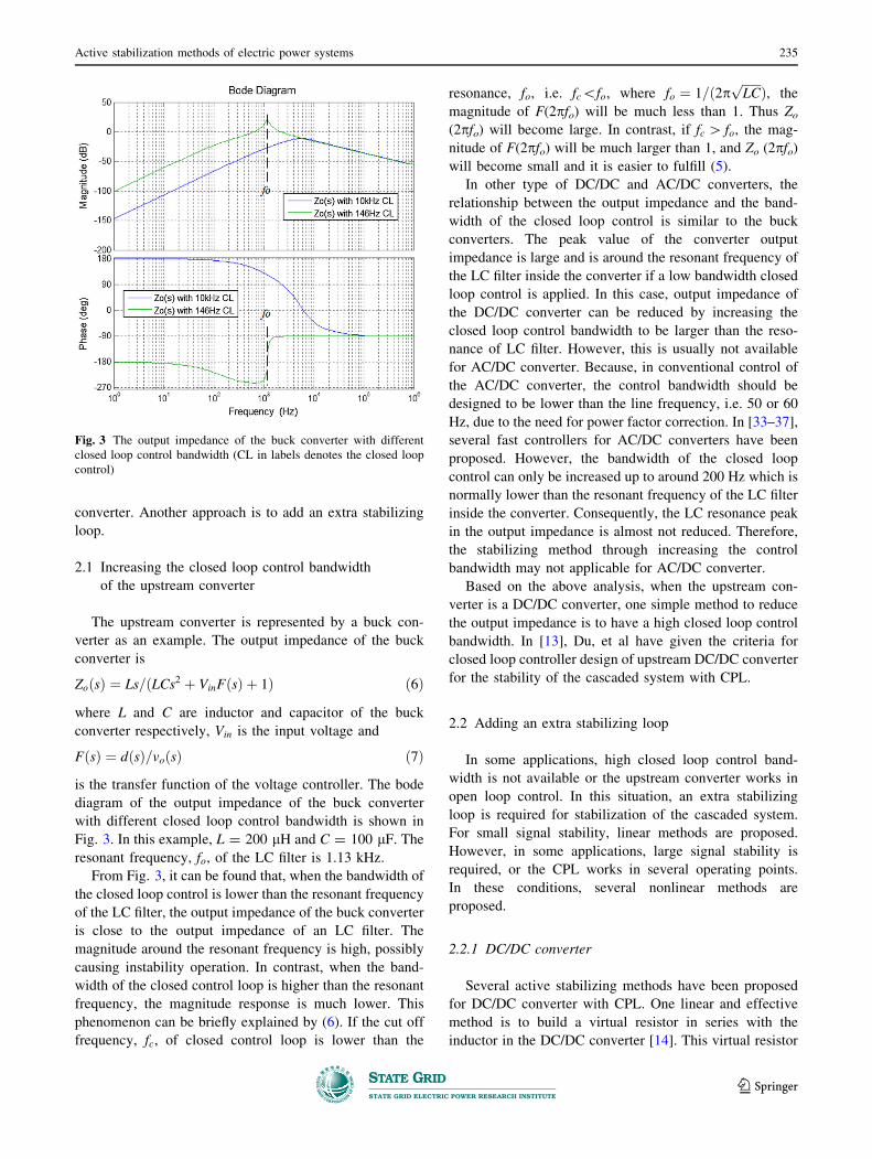
the closed loop control as illustrated in Fig. 3. The rela-
tionship between the bandwidth of the closed loop control
and the output impedance of the converter will be illus-
trated and explained in Section 2.1. Meanwhile, if the
converter works in discontinuous conduction mode (DCM),
zero inductor current operation changes the small signal
operation of the inductor. Consequently, the output
impedance of the converter may change and the cascaded
system is stable. The stability analysis of DC/DC converter
in DCM is presented in [31, 32].
This paper focuses on the stabilizing method of
switching converters in CCM. A general approach to sta-
bilizing this type of systems is to modify the output
impedance of the source converter. One approach is to
increase the closed loop control bandwidth of the source
Upstreamcircuits
Down-streamcircuits
Zo(s) Zi(s)
vA_in vA_o
+
_vB_ovB_in
+
_
+
_
+
_
GA(s)=vA_o/vA_in GB(s)=vB_o/vB_in
Fig. 1 The cascaded system for illustration of system stability
CPL
+
_
u
Powerelectroniccircuits
Vin
+
_
Upstreamcircuit Zo(s) Zin(s)
Za(s)
Fig. 2 Three main approaches of active damping methods
234 Mingfei WU, Dylan Dah-Chuan LU
123
converter. Another approach is to add an extra stabilizing
loop.
2.1 Increasing the closed loop control bandwidth
of the upstream converter
The upstream converter is represented by a buck con-
verter as an example. The output impedance of the buck
converter is
Zo sð Þ ¼ Ls=ðLCs2 þ VinF sð Þ þ 1Þ ð6Þ
where L and C are inductor and capacitor of the buck
converter respectively, Vin is the input voltage and
F sð Þ ¼ dðsÞ=voðsÞ ð7Þ
is the transfer function of the voltage controller. The bode
diagram of the output impedance of the buck converter
with different closed loop control bandwidth is shown in
Fig. 3. In this example, L = 200 lH and C = 100 lF. The
resonant frequency, fo, of the LC filter is 1.13 kHz.
From Fig. 3, it can be found that, when the bandwidth of
the closed loop control is lower than the resonant frequency
of the LC filter, the output impedance of the buck converter
is close to the output impedance of an LC filter. The
magnitude around the resonant frequency is high, possibly
causing instability operation. In contrast, when the band-
width of the closed control loop is higher than the resonant
frequency, the magnitude response is much lower. This
phenomenon can be briefly explained by (6). If the cut off
frequency, fc, of closed control loop is lower than the
resonance, fo, i.e. fc\fo, where fo ¼ 1=ð2pffiffiffiffiffiffi
LCp
Þ, the
magnitude of F(2pfo) will be much less than 1. Thus Zo
(2pfo) will become large. In contrast, if fc [ fo, the mag-
nitude of F(2pfo) will be much larger than 1, and Zo (2pfo)
will become small and it is easier to fulfill (5).
In other type of DC/DC and AC/DC converters, the
relationship between the output impedance and the band-
width of the closed loop control is similar to the buck
converters. The peak value of the converter output
impedance is large and is around the resonant frequency of
the LC filter inside the converter if a low bandwidth closed
loop control is applied. In this case, output impedance of
the DC/DC converter can be reduced by increasing the
closed loop control bandwidth to be larger than the reso-
nance of LC filter. However, this is usually not available
for AC/DC converter. Because, in conventional control of
the AC/DC converter, the control bandwidth should be
designed to be lower than the line frequency, i.e. 50 or 60
Hz, due to the need for power factor correction. In [33–37],
several fast controllers for AC/DC converters have been
proposed. However, the bandwidth of the closed loop
control can only be increased up to around 200 Hz which is
normally lower than the resonant frequency of the LC filter
inside the converter. Consequently, the LC resonance peak
in the output impedance is almost not reduced. Therefore,
the stabilizing method through increasing the control
bandwidth may not applicable for AC/DC converter.
Based on the above analysis, when the upstream con-
verter is a DC/DC converter, one simple method to reduce
the output impedance is to have a high closed loop control
bandwidth. In [13], Du, et al have given the criteria for
closed loop controller design of upstream DC/DC converter
for the stability of the cascaded system with CPL.
2.2 Adding an extra stabilizing loop
In some applications, high closed loop control band-
width is not available or the upstream converter works in
open loop control. In this situation, an extra stabilizing
loop is required for stabilization of the cascaded system.
For small signal stability, linear methods are proposed.
However, in some applications, large signal stability is
required, or the CPL works in several operating points.
In these conditions, several nonlinear methods are
proposed.
2.2.1 DC/DC converter
Several active stabilizing methods have been proposed
for DC/DC converter with CPL. One linear and effective
method is to build a virtual resistor in series with the
inductor in the DC/DC converter [14]. This virtual resistor
Fig. 3 The output impedance of the buck converter with different
closed loop control bandwidth (CL in labels denotes the closed loop
control)
Active stabilization methods of electric power systems 235
123

reduces the peak value of the output impedance. The
configuration of this stabilizing loop is shown in Fig. 4 and
is named as Method I. In Fig. 4, a buck converter is used as
an example. Another method is to add a nonlinear feedback
loop to cancel the nonlinearity of the CPL and thus stabi-
lize the system [15]. In small signal analysis, this method
builds a virtual resistor in parallel with the CPL. Thus, the
output impedance of the DC/DC converter can be reduced.
The configuration of this method is illustrated in Fig. 4 and
named as Method II. The bode diagram of the output
impedance of the buck converter with these two methods is
shown in Fig. 5.
From Fig. 5, it can be observed that both Methods I and
II can effectively reduce the output impedance of the DC/
DC converter around the resonant frequency of LC filter. In
Method I, the virtual resistor Rv, has to be within the small
or large signal stability criteria as shown in (8) and (9)
respectively [38].
L=CR\Rv\R ð8Þffiffiffiffiffiffiffiffiffi
L=Cp
\Rv\R ð9Þ
where L and C are the inductor and capacitor of the buck
converter and R is the resistor of the CPL. However, if the
ratio of L=C is large and R is small, Rv may not exist. In
contrast, in Method II, given any power level of CPL, there
always exist a constant K to stabilize the cascaded system.
In addition, in Method I, a current sensor is used mean-
while a voltage sensor is used in Method II.
In addition, there are other nonlinear active stabilization
methods. Sliding mode control is proposed for stabilization
of a DC/DC buck converter with CPL. The benefits of this
method is that it can stabilize the cascaded system in
several operating points [18]. A passivity based control
method is also proposed for a DC/DC boost converter. The
main advantage of this method is that it can obtain a fast
response when load condition changes [19]. A boundary
control method for DC/DC converter with CPL is proposed
in [16, 17]. This method can provide faster transient, more
robust operation compared with conventional PID con-
troller. However, all these three methods require both
voltage and current sensors.
2.2.2 AC/DC converter
The upstream converter can also be an AC/DC con-
verter. In [20], a linear active stabilization method by
modifying the output impedance of AC/DC converter is
presented. Three kinds of stabilizing loop are proposed and
compared. The configuration of the most effective stabi-
lizing loop is shown in Fig. 6. The output impedance of the
AC/DC converter with this stabilizing loop is shown in
Fig. 7. With the stabilizing method, the output impedance
of the AC/DC converter can be reduced and the Middle-
brook’s stability criterion can be fulfilled.
In addition, sliding mode control method is also pro-
posed for AC/DC converters with CPLs. Sliding mode
control guarantees the stability in large range of operating
points [21]. However, this method requires both voltage
and current sensors.
3 Active damping method 2: modifying the input
impedance ZinðsÞ of CPLs
In some DC power electric systems, the feeder of a CPL
is an LC input filter. In addition, in AC power systems, a
CPLC+
_vo
d
Vin
+
_
C(s)
L
Vref_
iL
Rv_
Method I
BPF y=K/vo
Method IIas/(s+a)
+
Upstream converter
Fig. 4 The configuration of the two extra stabilizing loops for a buck
converter loaded by CPL
Fig. 5 Bode diagrams of the output impedances of the buck
converter with the two active damping methods
236 Mingfei WU, Dylan Dah-Chuan LU
123

diode type rectifier is equivalent to an LC filter as shown in
Fig. 8. In Fig. 8, an AC load is used as an example but it
can also be a DC load.
In these configurations, the upstream circuit is a passive
LC filter. High bandwidth control of the upstream circuit is
not available. Therefore, the damping effort can be only
from CPLs themselves. In order to stabilize such cascaded
system, some active damping methods have been proposed.
These methods can be classified into linear methods and
nonlinear methods. In linear methods, compensating cur-
rent are injected into the CPL to modify the input imped-
ance of CPL, ZinðsÞ, such that Middlebrook’s stability
criterion is fulfilled.
3.1 Linear methods
In linear methods, a stabilizing power is injected into the
CPL to modify its input impedance. The configuration of
the linear methods is shown in Fig. 9.
The operation of the cascaded system with linear
methods can be described in (10).
di
dt¼ �RL
Li � 1
Lu þ 1
LVin
du
dt¼ 1
Ci � P þ Pstab
Cu
8
>
<
>
:
ð10Þ
where, i and u are inductor current and capacitor voltage
respectively. L and C are the inductor and capacitor of the
LC filter respectively. RL is the equivalent resistor of the
power cable and physical resistor of the inductor. Vin is the
input voltage of the LC filter. P is the power of CPL and
Pstab is the power used for stabilize the system. Pstab is
injected into the CPL to build virtual resistor or virtual
capacitor parallel connected with LC filter capacitor
depending on different linear methods as illustrated in
Fig. 9.
There are two requirements for Pstab [39].
1) With Pstab, the input impedance of the CPL can be
modified to fulfill the Middlebrook’s stability
criterion.
2) In steady state operation, Pstab ¼ 0.
In the linear methods, the stabilizing power Pstab is
represented by stabilizing current, istab and
0
20
-20
100 100010
Zin(s)
Zo(s)Zo’(s)
Frequency (Hz)
Mag
nitu
de (
dB)
Fig. 7 The magnitude response of the output impedance of the AC/
DC converter without stabilizing method (in solid black) and with
stabilizing method (in solid red)
VSI
Lac
Lac
Lac
Rac
Rac
RacCac PMSM
Controller
RL L
C
Equivalent circuit
VSI PMSM
Controller
RL L
C P/u+
_ui
AC power supplies a CPL
DC power supplies a CPLLC input filter
LC input filter CPL
Fig. 8 A CPL in AC power system and DC power system and their
equivalent circuit
VSC
L
L
L
R
R
RC
abc/dq
iabc
vabc
vdc+
_
Vdc_ref
_Cv(s)
id_refid
Ci(s)
_
ωLiq
vd_refvd
LPFYv
_
_
Stabilizing loop
Fig. 6 The configuration of the stabilizing loop in the AC/DC
converter
Active stabilization methods of electric power systems 237
123

istab ¼ Pstab
Cuð11Þ
After linearization around the operation point, (10) can be
rewritten as
di
dt¼ �RL
Li � 1
Lu þ 1
LVin
du
dt¼ 1
Ci þ u
CRþ istab
8
>
<
>
:
ð12Þ
where R is the resistance of the CPL.
In order to see the effectiveness of active stabilization
methods, the performances of the DC brushless motor
without damping methods are shown in Fig. 10. From
Fig. 10, it can be found that, during the start of the motor,
when the rotating speed xr is small, P is small and R is
large and is larger than kZoðsÞk. Hence, the system is sta-
ble. However, when xr increases larger, then R becomes
small and is smaller than kZoðsÞk, the system becomes
unstable.
3.1.1 Virtual resistor Rv [2, 23–25]
Modifying (11) so that
istab ¼ CbðsÞuCRv
ð13Þ
where, CbðsÞ is the transfer function of a band pass filter with
unity gain, it represents a virtual resistor Rv that is being
built in parallel with the LC filter capacitor. The function of
the band pass filter is to pick the oscillation component which
is around the resonant frequency of the LC filter and atten-
uate the steady state value and switching noises. In order to
stabilize the system, Rv needs to be chosen such that Mid-
dlebrook’s stability criterion is fulfilled as shown in Fig. 11.
3.1.2 Virtual capacitor Cv [22, 23]
When (11) is modified so that,
istab ¼ sCvCl sð ÞuC
ð14Þ
where ClðsÞ is a low pass filter with unity gain, a virtual
capacitor Cv is built in parallel with the LC filter capacitor.
Thus the overall capacitance of the LC filter is increased.
Also, the value of Cv needs to be chosen to make the Mid-
dlebrook’s stability criterion fulfilled as shown in Fig. 12.
3.1.3 Comparison
From Figs. 13 and 14, it can be found that, the perfor-
mance of active damping method by building Rv is better
Fig. 10 The performances of the DC brushless motor without
damping methods
VSI+
_u
L
C
Stabilizer
u
Pstab Pconst
Pref
Band pass filter
ubp
RL
Linear stabilizing loop
Motor
PWMgenerator
Closed loop control
RL L
C Pcomp/u+
_ui
LC input filter CPL
Controller
P/u
L
C
RL
Function of these linear methods
Equivalent circuit
P/u
+
_Vin
+
_Vin
Fig. 9 The configuration of the cascaded system with linear methods
238 Mingfei WU, Dylan Dah-Chuan LU
123
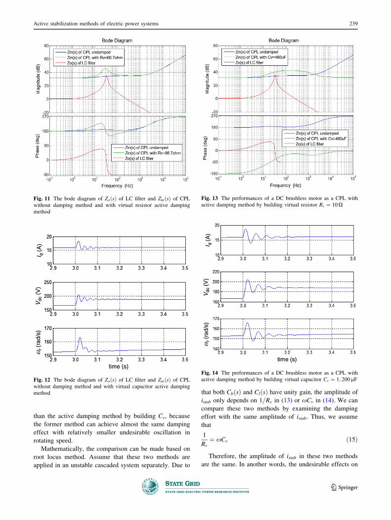
than the active damping method by building Cv, because
the former method can achieve almost the same damping
effect with relatively smaller undesirable oscillation in
rotating speed.
Mathematically, the comparison can be made based on
root locus method. Assume that these two methods are
applied in an unstable cascaded system separately. Due to
that both CbðsÞ and ClðsÞ have unity gain, the amplitude of
istab only depends on 1=Rv in (13) or xCv in (14). We can
compare these two methods by examining the damping
effort with the same amplitude of istab. Thus, we assume
that
1
Rv
¼ xCv ð15Þ
Therefore, the amplitude of istab in these two methods
are the same. In another words, the undesirable effects on
Fig. 12 The bode diagram of ZoðsÞ of LC filter and ZinðsÞ of CPL
without damping method and with virtual capacitor active damping
method
Fig. 13 The performances of a DC brushless motor as a CPL with
active damping method by building virtual resistor Rv ¼ 10 X
Fig. 14 The performances of a DC brushless motor as a CPL with
active damping method by building virtual capacitor Cv ¼ 1; 200 lF
Fig. 11 The bode diagram of ZoðsÞ of LC filter and ZinðsÞ of CPL
without damping method and with virtual resistor active damping
method
Active stabilization methods of electric power systems 239
123

the load performance are the same. A series of Rv and Cv
are selected as shown in (16) and (17).
Cv ¼ 0:5Ci ð16Þ
Rv ¼1
0:5xCið17Þ
where i ¼ 1; 2; . . .; 8: The root loci of the cascaded system
with two active methods are shown separately in
Fig. 15.
In Fig. 15, it can be observed that when i increases, the
poles of the system with the method of building virtual
resistor can approach to the negative real part much quicker
comparing with the method of building virtual capacitor.
Therefore, with the same amplitude of istab, i.e. the same
undesirable effect on the load performance, the damping
effort of the method of building virtual resistor is better
than the method of building virtual capacitor.
3.2 Nonlinear methods
Sudhoff S. D. et al proposed a nonlinear method [28].
However, this method has limited damping effect com-
pared with the linear method. This has been presented in
[39]. A passivity based control method is proposed in [39].
This passivity based control can provide better damper
without large undesirable load performance. The passivity
based control algorithm is shown in (13) and (14).
h ¼ �RL
P
Vdc
þ R1 i � P
Vdc
� �
þ Vin ð18Þ
Pstab ¼ uP
Vdc
� Cdhdt
� �
� P þ ðu � hÞuR2
ð19Þ
where R1 and R2 are two coefficients. h and Vdc are ref-
erence value of i and u. However, complicated calculation
with measurements i, u and P as shown (18) and (19) can
result in large error and noises. As a result, this method is
difficult to be implemented.
3.3 Sensitivity and availability
As shown in Fig. 9, a stabilizing power is injected into
the CPL to stabilize the cascaded system. This stabilizing
power is a transient oscillating component. It can result in
undesirable load performances, such as the oscillation in
the rotating speed of the motors. Therefore, there is always
a compromise between the damping of the oscillation in
LC input filter and the load performances. Therefore,
sensitivity from input voltage of CPL to the rotating speed
is important in the design of active stabilization method.
As the injected power is realized by the downstream
converters, a large stabilizing power injected into the CPL
is required to achieve a greater damping effect. This
implies a wide range of duty cycle values in the down-
stream converters. However, the duty cycles are within the
range of (0, 1). Therefore, the stabilizing effect is limited
by available duty cycle range, e.g. high step-up converters
usually operate at duty cycle between 0.5 and 1. Thus the
availability of the stabilizing effect of the active stabil-
ization method is another aspect to be considered.
4 Active damping method 3: adding a shunt impedance
ZaðsÞ
Owing to the sensitivity and availability problems in the
active stabilization in Section 3, a new type of methods are
proposed. In this type of methods, an auxiliary DC/DC
converter is added across the input voltage of the CPL.
This DC/DC converter works as a power buffer and also
Fig. 15 a The root loci of the cascaded system with method of
building virtual resistor Rv (in red) and with method of building
virtual capacitor Cv (in blue) and b the details around zero
240 Mingfei WU, Dylan Dah-Chuan LU
123

can be designed to decouple the interaction between the
CPL and its LC input filter.
As shown in Fig. 16, an auxiliary power electronic cir-
cuit is added to stabilize the system. The input current ic is
controlled depending on the input voltage u to control its
input impedance ZaðsÞ. In order to fulfill the Middlebrook’s
stability, ZaðsÞ should fulfill
Zo sð Þk k\ ZaðsÞZinðsÞZa sð Þ þ ZinðsÞ
�
�
�
�
�
�
�
�
ð20Þ
Or
ZaðsÞZoðsÞZa sð Þ þ ZoðsÞ
�
�
�
�
�
�
�
�
\ Zin sð Þk k ð21Þ
In addition, jjZa sð Þjj should approach infinity when
frequency is zero.
Theoretically, this auxiliary DC/DC converter can sta-
bilize the system as the CPL does as described in Section 3
and it does not inherit the sensitivity problem. It can work
as a virtual resistor or a virtual capacitor or use to realize
nonlinear methods.
In [30], an auxiliary DC/DC converter is presented to
mimic a virtual capacitor. This is realized by the control of
the input current of the auxiliary DC/DC converter, ic,
according to the capacitor voltage u. i.e.
ic ¼ Cv
du
dtð22Þ
where Cv is the virtual capacitor.
In [29], an auxiliary DC/DC converter is used to realize
a pole placement method. In this method, the duty cycle of
the auxiliary converter is controlled to replace the poles of
the whole dynamic system. The capacitor voltage, u, and
the input current of the auxiliary converter, ic, are mea-
sured and second order observer is used. Thus, all four
system states, inductor current of LC filter, i, capacitor
voltage of the auxiliary converter, vc, ic and u are available
for controller design. Therefore, the poles of the closed
loop control system can be replaced to obtain a good
damping performance.
5 Comparison and conclusion
This paper analyzes several existing active stabilization
methods. The methods have been evaluated through Mid-
dlebrook’s stability criterion. According to the source of
the stabilizing effect, these methods are classified into three
categories. The advantages and disadvantages of these
three types of methods are summarized as follows:
The active damping method which reduces the output
impedance of the upstream converter is discussed in Sec-
tion 2. The main advantage of this type of methods is that it
can stabilize the cascaded system without affecting the
operation and performance of CPL. The disadvantage of
these methods is that the upstream circuit needs to be
controllable, e.g. a switching regulator. These methods are
suitable on the systems in which the feeder of CPLs is
another stage converter.
The active damping method which increases the input
impedance of the CPL is discussed in Section 3. The main
merit is that the CPL can overcome the negative impedance
instability by itself. These methods are suitable for the
systems in which the feeder of CPL is an uncontrollable LC
filter. The demerit of these methods is that the stabilizing
power injected into the CPL can result in some undesirable
load performances. There is always a compromise between
the damping effect and the load performances.
The active damping methods by adding a shunt
impedance through an extra power electronics circuit is
discussed in Section 4. The strength of this method is that
the extra power electronic converter can stabilize the sys-
tem without the undesirable effect on the load perfor-
mances. This type of methods has a high potential to
achieve similar function as the CPL does to stabilize the
system, but without the compromise. The weak side is that
extra circuit is required resulting in additional cost and
power losses.
Open Access This article is distributed under the terms of the
Creative Commons Attribution License which permits any use, dis-
tribution, and reproduction in any medium, provided the original
author(s) and the source are credited.
References
[1] Rahimin AM, Khaligh A, Emadi A (2006) Design and imple-
mentation of an analog constant power load for studying cas-
caded converters. In: Proceedings of the 32nd annual conference
CPL
+
_
u
ic
Vin
+
_
Upstreamcircuit
Controller
d
Zo(s) Zin(s)
Za(s)
Fig. 16 The schematic diagram of the extra power electronic circuit
Active stabilization methods of electric power systems 241
123

on IEEE industrial electronics society (IECON’06), Paris, 6–10
Nov 2006, pp 1709–1714
[2] Liu XY, Forsyth AJ, Cross AM (2007) Negative input-resistance
compensator for a constant power load. IEEE Trans Ind Electron
54(6):3188–3196
[3] Kwasinski A, Krein PT (2007) Passivity-based control of buck
converters with constant-power loads. In:Proceedings of the
2007 IEEE power electronics specialists conference (PESC’07),
Orlando, 17–21 Jun 2007, pp 259–265
[4] Emadi A, Khaligh A, Rivetta CH et al (2006) Constant power loads
and negative impedance instability in automotive systems: Defini-
tion, modeling, stability, and control of power electronic converters
and motor drives. IEEE Trans Veh Technol 55(4):1112–1125
[5] Rivetta C, Williamson GA (2004) Global behaviour analysis of a
DC-DC boost power converter operating with constant power
load. In: Proceedings of the 2004 international symposium on
circuits and systems (ISCAS’04), vol 5. Vancouver, Canada,
23–26 May 2004, pp 956–959
[6] Rivetta CH, Emadi A, Williamson GA et al (2006) Analysis and
control of a buck DC-DC converter operating with constant
power load in sea and undersea vehicles. IEEE Trans Ind Appl
42(2):559–572
[7] Rahimi AM, Emadi A (2009) An analytical investigation of DC/DC
power electronic converters with constant power loads in vehicular
power systems. IEEE Trans Veh Technol 58(6):2689–2702
[8] Riccobono A, Santi E (2012) Comprehensive review of stability
criteria for DC power distribution systems. In: Proceedings of
the 2012 IEEE energy conversion congress and exposition
(ECCE’12), Raleigh, 15–20 Sept 2012, pp 3917–3925
[9] Middlebrook RD (1976) Input filter considerations in design and
application of switching regulators. In: Proceedings of the IEEE
industry applications society annul meeting (IAS’76), Chicago,
11–14 Oct 1976, pp 366–382
[10] Wildrick CM, Lee FC, Cho BH et al (1995) A method of
defining the load impedance specification for a stable distributed
power system. IEEE Trans Power Electron 10(3):280–285
[11] Sudhoff SD, Glover SF, Lamm PT et al (2000) Admittance
space stability analysis of power electronic systems. IEEE trans
aero electron syst 36(3-Part 1):965–973
[12] Feng XG, Liu JJ, Lee FC (2002) Impedance specifications for
stable DC distributed power systems. IEEE Trans Power Elec-
tron 17(2):157–162
[13] Du W, Zhang J, Zhang Y et al (2013) Stability criterion for
cascaded system with constant power load. IEEE Trans Power
Electron 28(4):1843–1851
[14] Rahimi AM, Emadi A (2009) Active damping in DC/DC power
electronic converters: A novel method to overcome the problems of
constant power loads. IEEE Trans Ind Electron 56(5):1428–1439
[15] Rahimi AM, Williamson GA, Emadi A (2010) Loop-cancella-
tion technique: A novel nonlinear feedback to overcome the
destabilizing effect of constant-power loads. IEEE Trans Veh
Technol 59(2):650–661
[16] Onwuchekwa CN, Kwasinski A (2009) Boundary control of
buck converters with constant-power loads. In: Proceedings of
the 31st international telecommunications energy conference
(INTELEC’09), Incheon, 18–22 Oct 2009, 6 pp
[17] Onwuchekwa CN, Kwasinski A (2011) Analysis of boundary
control for boost and buck-boost converters in distributed power
architectures with constant-power loads. In: Proceedings of the
26th annual IEEE applied power electronics conference and
exposition (APEC’11), Fort Worth, 6–11 Mar 2011, pp 1816–1823
[18] Zhao Y, Qiao W, Ha D (2014) A sliding-mode duty-ratio con-
troller for DC/DC buck converters with constant power loads.
IEEE Trans Ind Appl 50(2):1448–1458
[19] Zeng J, Zhang Z, Qiao W (2014) An interconnection and
damping assignment passivity-based controller for a DC-DC
boost converter with a constant power load. IEEE Trans Ind
Appl 50(4):2314–2322
[20] Radwan AAA, Mohamed YARI (2012) Linear active stabiliza-
tion of converter-dominated DC microgrids. IEEE Trans Smart
Grid 3(1):203–216
[21] Zhang XN, Vilathgamuwa DM, Foo G, et al (2013) Cascaded
sliding mode control for global stability of three phase AC/DC
PWM rectifier with rapidly varying power electronic loads. In:
Proceedings of the 39th annual conference of the IEEE industrial
electronics society, (IECON’13), Vienna, 10–13 Nov 2013,
pp 4580–4587
22. Magne P, Marx D, Nahid-Mobarakeh B et al (2012) Large-signal
stabilization of a DC-link supplying a constant power load using
a virtual capacitor: Impact on the domain of attraction. IEEE
Trans Ind Appl 48(3):878–887
[23] Mohamed YARI, Radwan AAA, Lee TK (2012) Decoupled
reference-voltage-based active DC-link stabilization for PMSM
drives with tight-speed regulation. IEEE Trans Ind Electron
59(12):4523–4536
[24] Lee WJ, Sul SK (2014) DC-link voltage stabilization for
reduced DC-link capacitor inverter. IEEE Trans Ind Appl
50(1):404–414
[25] Liutanakul P, Awan AB, Pierfederici S et al (2010) Linear
stabilization of a DC bus supplying a constant power load: A
general design approach. IEEE Trans Power Electron 25(2):
475–488
[26] Glover SF, Sudhoff SD (1998) An experimental validated non-
linear stabilizing control for power electronics based power
systems. In: Proceedings of the SAE aerospace power system
conference (APSC’98), Detroit, 21–23 Apr 1998, pp 71–88
[27] Mosskull H, Galic J, Wahlberg B (2007) Stabilization of
induction motor drives with poorly damped input filters. IEEE
Trans Ind Electron 54(5):2724–2734
[28] Sudhoff SD, Corzine KA, Glover SF et al (1998) DC link sta-
bilized field oriented control of electric propulsion system. IEEE
Trans Energ Conver 13(1):27–33
[29] Inoue K, Kato T, Inoue M, et al (2012) An oscillation sup-
pression method of a DC power supply system with a constant
power load and a LC filter. In: Proceedings of the IEEE 13th
workshop on control and modeling for power electronics
(COMPEL’12), Kyoto, 10–13 Jun 2012, 4 pp
[30] Zhang X, Ruan X, Kim H et al (2013) Adaptive active capacitor
converter for improving stability of cascaded DC power supply
system. IEEE Trans Power Electron 28(4):1807–1816
[31] Grigore V, Hatonen J, Kyyra J et al (1998) Dynamics of a buck
converter with a constant power load. In: Proceedings of the
29th annual IEEE power electronics specialists conference
(PESC’98), vol 1. Fukuoka, 17–22 May 1998, pp 72–78
[32] Rahimi AM, Emadi A (2010) Discontinuous-conduction mode
DC/DC converters feeding constant-power loads. IEEE Trans
Ind Electron 57(4):1318–1329
[33] Spiazzi G, Mattavelli P, Rossetto L (1997) Power factor pre-
regulators with improved dynamic response. IEEE Trans PowerElectron 12(2):343–349
[34] Prodic A, Chen JQ, Maksimovic D, et al (2003) Self-tuning
digitally controlled low-harmonic rectifier having fast dynamic
response. IEEE trans power electron 18(1-Part 2):420–428
[35] Lamar DG, Fernandez A, Arias M et al (2008) A unity power
factor correction preregulator with fast dynamic response based
on a low-cost microcontroller. IEEE Trans Power Electron
23(2):635–642
[36] Wall S, Jackson R (1997) Fast controller design for single-phase
power-factor correction systems. IEEE Trans Ind Electron
44(5):654–660
[37] Rezaei K, Golbon N, Moschopoulos G(2014) A new control
scheme for an AC-DC single-stage buck-boost PFC converter
242 Mingfei WU, Dylan Dah-Chuan LU
123

with improved output ripple reduction and transient response. In:
Proceedings of the 29th annual IEEE applied power electronics
conference and exposition (APEC’14), Fort Worth, 16-20 Mar
2014, pp 1866–1873
[38] Belkhayat M, Cooley R, Witulski A (1995) Large signal stability
criteria for distributed systems with constant power loads. In:
Proceedings of the 26th annual IEEE power electronics spe-
cialists conference (PESC ‘95), vol 2. Atlanta, 18–22 Jun 1995,
pp 1333–1338
[39] Liu XY, Forsyth AJ (2005) Comparative study of stabilizing
controllers for brushless DC motor drive systems. In: Proceedings
of the 2005 IEEE international conference on electric machines and
drives, San Antonio, 15–18 May 2005, pp 1725–1731
Mingfei WU received the B.Eng. degree in Electrical and Electronic
Engineering from Northumbria University, UK, and M.Sc. degree in
Control Systems from Imperial College London, UK, in 2009 and
2010, respectively. From 2012, he started to pursue his Ph.D. degree
in the University of Sydney, Australia. His current research focuses
on the stability of DC microgrids.
Dylan DAH-CHUAN LU received his Ph.D. degree in Electronic
and Information Engineering from The Hong Kong Polytechnic
University, Hong Kong, China, in 2004. In 2003, he joined
PowereLab Ltd. as a Senior Engineer. His major responsibilities
include project development and management, circuit design, and
contribution of research in the area of power electronics. In 2006, he
joined the School of Electrical and Information Engineering, The
University of Sydney, Australia, where he is currently a Senior
Lecturer. He presently serves as an Associate Editor of the
International Journal of Electronics, and the Australian Journal of
Electrical and Electronics Engineering. He is an author/co-author of
over 90 technical articles in the areas of power electronics and
engineering education. He has two patents on efficient power
conversion. His current research interests include power electronics
circuits and control for efficient power conversion, lighting, renew-
able electrical energy systems, microgrid and power quality improve-
ment, and engineering education. Dr. LU received the Dean’s
Research Award in 2011. He is a senior member of the IEEE and a
member of the IEAust.
Active stabilization methods of electric power systems 243
123