active vibration control of journal bearings with the...
TRANSCRIPT
Active vibration control of journal bearings with the use of piezoactuators 141
Active vibration control of journal bearings with the use of piezoactuators
Jiří Tůma, Jiří Šimek, Jaromír Škuta and Jaroslav Los
X
Active vibration control of journal bearings with the use of piezoactuators
Jiří Tůma, Jiří Šimek, Jaromír Škuta and Jaroslav Los
Technical University of Ostrava, TECHLAB Ltd., Prague Czech Republic
1. Introduction
Rotor instability due to the oil film is one of the most serious problems of high-speed rotors supported in journal bearings. With constantly increasing parameters of new machines, problems with rotor instability are encountered more and more often. To study possibilities of affecting rotor behavior by controlled movement of bearing bushings, a test stand was designed, manufactured and assembled. Even though there are many solution based on passive improvements of the bearing geometry to enlarge the operational RPM range of the journal bearing as a lemon bore, pressure dam, tilting pad, etc., the approach to preventing the journal bearing instability, presented in the paper, is based on the use of the active vibration control.
2. Design of Journal Bearing for Active Vibration Control
Many authors pay attention to the active control of magnetic bearings, but use of piezoactuators is rarely studied. Worth mentioning are articles (Carmignani et al., 2001) and (Rho et al., 2002). Because of the lack of information, it was decided to start research of methods suppressing sliding journal bearing instability by the active vibration control. The research work was granted by the Czech Grant Agency as a part of the research project No. 101/07/1345 “Active control of journal bearings aimed at suppressing the rotor instability”. The control system adds an electronic feedback to the rotor-bearing system actuating the position of a movable bushing. The current passive damper changes into an active component of the system with controllable properties. Objectives of the research work were focused onto the experimental verification of theoretical knowledge about conditions of the onset of rotor instability, building up an experimental device used for tests of active control of the journal bearings, with the aim of suppressing rotor instability and designing the algorithm of stabilization of shaft movements inside the journal bearing, verified experimentally. The project was finished in 2009. This book chapter informs about results of the mentioned project. The laboratory test facilities including the journal bearing equipped with the movable bushing was designed by the TECHLAB Ltd., Prague. The research group of Technical University of Ostrava developed the control system, which is based on piezoactuators, and put the system into operation (Šimek et al., 2010) and (Tůma et al.,
7

Engineering the Future142
2010). The sketch of a controllable journal bearing arrangement, which is implemented for the active vibration control, is shown in Fig. 1. The test rig for testing of the control system will be described later.
Fig. 1. Arrangement of the controllable journal bearing
3. Mathematical Model of Controlled System
There are many ways how to model journal bearings, but this paper prefers an approach, which is based on the concept developed by (Muszynska, 1986) supported by Bently Rotor Dynamics Research Corporation (Bently et al., 1989). The reason for this is that this concept offers an effective way to understand the rotor instability problem and to model a journal vibration active control by manipulating the sleeve position by actuators, which are a part of the closed loop system composed of proximity probes and a controller. Another approach can be based on the lubricant flow prediction using a FE method for Reynolds equation solution. These more sophisticated methods do not allow analyzing behavior of the vibration active control to design and tune the controller. Let the rotor angular velocity is designated by in radians per a second. It is assumed that the bushing is a movable part in two perpendicular directions while rotor is rotating. This mathematical model proposes to use complex variables to describe motion of the rotor and bushing in the plane, which is perpendicular to the rotor axis. The coordinate system is tied to stationary bearing housing with a cylindrical hole, inside of which is inserted the movable bearing bushing. The positions of the journal centre and bushing mean the intersection of both the movable component axis with the mentioned complex plane. The origin of the complex plane is situated in the centre of the mentioned cylindrical hole as it is shown in Fig. 2. The position of the journal centre in the complex plane is designated by a position vector r while the position of the bushing is designated by a position vector u. (0, 0) – coordinates of the cylindrical hole center r = (x(t), y(t)) – coordinates of the journal (rotor) center u = (ux(t), uy(t)) – coordinates of the bushing center
Fig. 2. Coordinate system
3.1 Lumped Parameter Model of the Journal Bearing The internal spring, damping and tangential forces are acting on the rotor. The external forces refer to forces that are applied to the rotor, such as unbalance, impacts and preloads in the form of constant radial forces. All these external forces are considered as an input for the mathematical model. The fluid pressure wedge is the actual source of the fluid film stiffness in a journal bearing and maintains the rotor in equilibrium. As Muszynska has stated these bearing forces can be modeled by a spring and damper system, which is rotating at the angular velocity (see figure 3), where is a dimensionless parameter, which is slightly less than 0.5.
Fig. 3. Model of oil film The parameter is denominated by Muszynska as the fluid averaged circumferential velocity ratio. It is assumed that the rotating journal drags the fluid in a space between two cylinders into motion and acts as a pump. It is easy to understand that the fluid circular velocity is varying across the gap as a consequence of the fluid viscosity. The validity of Muszynska’s assumption can be verified experimentally. It is known that an oscillation (an onset of instability) of the rotor starts when the rotor rotational speed exceeds a certain value and stops when RPM decreases under the other one. It can be shown by experiment, that when the rotor system is excited by a non-synchronous perturbation force with respect to the rotor rotational speed, the resonance appears at the frequency, which is approximately equal to . The simulation is prepared to prove the same properties of the mathematical model, which is based on Muszynska’s theory.
Fluid wedge
Oil film
X (Re)
Y (Im)
(0,0)
r
u
bushing center
journal center
cylindrical hole center
Y (Im)
r
Ω
X (Re)
movable bushing
cylindrical hole
journal

Active vibration control of journal bearings with the use of piezoactuators 143
2010). The sketch of a controllable journal bearing arrangement, which is implemented for the active vibration control, is shown in Fig. 1. The test rig for testing of the control system will be described later.
Fig. 1. Arrangement of the controllable journal bearing
3. Mathematical Model of Controlled System
There are many ways how to model journal bearings, but this paper prefers an approach, which is based on the concept developed by (Muszynska, 1986) supported by Bently Rotor Dynamics Research Corporation (Bently et al., 1989). The reason for this is that this concept offers an effective way to understand the rotor instability problem and to model a journal vibration active control by manipulating the sleeve position by actuators, which are a part of the closed loop system composed of proximity probes and a controller. Another approach can be based on the lubricant flow prediction using a FE method for Reynolds equation solution. These more sophisticated methods do not allow analyzing behavior of the vibration active control to design and tune the controller. Let the rotor angular velocity is designated by in radians per a second. It is assumed that the bushing is a movable part in two perpendicular directions while rotor is rotating. This mathematical model proposes to use complex variables to describe motion of the rotor and bushing in the plane, which is perpendicular to the rotor axis. The coordinate system is tied to stationary bearing housing with a cylindrical hole, inside of which is inserted the movable bearing bushing. The positions of the journal centre and bushing mean the intersection of both the movable component axis with the mentioned complex plane. The origin of the complex plane is situated in the centre of the mentioned cylindrical hole as it is shown in Fig. 2. The position of the journal centre in the complex plane is designated by a position vector r while the position of the bushing is designated by a position vector u. (0, 0) – coordinates of the cylindrical hole center r = (x(t), y(t)) – coordinates of the journal (rotor) center u = (ux(t), uy(t)) – coordinates of the bushing center
Fig. 2. Coordinate system
3.1 Lumped Parameter Model of the Journal Bearing The internal spring, damping and tangential forces are acting on the rotor. The external forces refer to forces that are applied to the rotor, such as unbalance, impacts and preloads in the form of constant radial forces. All these external forces are considered as an input for the mathematical model. The fluid pressure wedge is the actual source of the fluid film stiffness in a journal bearing and maintains the rotor in equilibrium. As Muszynska has stated these bearing forces can be modeled by a spring and damper system, which is rotating at the angular velocity (see figure 3), where is a dimensionless parameter, which is slightly less than 0.5.
Fig. 3. Model of oil film The parameter is denominated by Muszynska as the fluid averaged circumferential velocity ratio. It is assumed that the rotating journal drags the fluid in a space between two cylinders into motion and acts as a pump. It is easy to understand that the fluid circular velocity is varying across the gap as a consequence of the fluid viscosity. The validity of Muszynska’s assumption can be verified experimentally. It is known that an oscillation (an onset of instability) of the rotor starts when the rotor rotational speed exceeds a certain value and stops when RPM decreases under the other one. It can be shown by experiment, that when the rotor system is excited by a non-synchronous perturbation force with respect to the rotor rotational speed, the resonance appears at the frequency, which is approximately equal to . The simulation is prepared to prove the same properties of the mathematical model, which is based on Muszynska’s theory.
Fluid wedge
Oil film
X (Re)
Y (Im)
(0,0)
r
u
bushing center
journal center
cylindrical hole center
Y (Im)
r
Ω
X (Re)
movable bushing
cylindrical hole
journal

Engineering the Future144
Fluid forces acting on the rotor in coordinates rotating at the same angular frequency as the spring and damper system are determined by the position of the journal centre relating to the bushing centre and therefore are given by the formula (Tondl, 1991) rotrotrotrotrot DK ururF , (1) where parameters, K and D , are specifying proportionality of stiffness and damping to the relative position of the journal centre displacement vector rotrot ur and velocity vector
rotrot ur , respectively. To model the rotor system, the fluid forces have to be expressed in the stationary coordinate system, in which the rotor centre-line displacement and velocity vectors are designated by r and r , respectively. Conversion the complex rotating vector rotr to the stationary coordinate system can be done by multiplication this vector by tj exp , which is the same as multiplying the vector in the stationary coordinates by tj exp , see Fig. 4.
Fig. 4. Transform rotating coordinate to stationary coordinate The relationship between the mentioned vectors in rotating and stationary coordinates are given by the formulas
tjjtjjtjtj
rotrot
rotrot
expexp
expexpuuurrr
uurr
(2)
Substitution (2) into the fluid force equation (1) results in the following formula urururF jDDK (3) where the complex term rjD has the meaning of the force acting tangentially to the direction of the vector r . As the rotor angular velocity increases, this force can become very big and can cause rotor instability . As was mentioned, the rotor is under influence of the external forces, for instance produced by unbalance or simply by gravity. To obtain general solution this external perturbation force, resulting from unbalance, is assumed to be rotating at the angular velocity , which is considered to be completely independent of the rotor angular velocity . The unbalance force, which is produced by unbalance mass m located at a radius ur , acts in the radial direction and has a phase at time 0t
Stationary
Rotatingr
t
tjmruonPerturbati exp2F (4) The equation of motion for a rigid rotor operating in a small, localized region in the journal bearing, is as follows tjmrjDKDM u exp2ururr , (5)
where M is the total rotor mass. The trajectory of the rotor centerline is called an orbit.
3.2 Equation of motion as a servomechanism For the stability analysis of the journal bearing it is assumed, that the bushing is not moving u = 0. According Muszynska the rotor/fluid wedge bearing/system can be demonstrated as a servomechanism working in the closed loop, which is shown in Fig. 5. The direct and quadrature dynamic stiffness is introduced according to the acting force direction. To obtain the Laplace transform of the motion equation, the imaginary variable j is replaced by a complex variable s 2MsDsKsKDirect (6) DjsKQuadrature (7) and the equation of motion (6) takes the form sKsK DirectQuadratureonPerturbati rFr (8)
The transfer function sKDirect1 (direct dynamic compliance) is stable. The feedback path in the closed-loop system acts as a positive feedback and introduces instability for the closed-loop system. The gain of the positive feedback depends on the rotor angular velocity . The closed-loop system is stable for the low rotor rotational speed. But there is a margin for the stable behavior. If the gain of the positive feedback crosses over some limit value then the closed-loop becomes unstable. The stability of the closed-loop dynamic system is depending on the open-loop frequency transfer function for js
20
MKjDD
jKjK
jGDirect
Quadrature (9)
As it is known the closed-loop dynamic system is stable according to the Nyquist stability criterion if, and only if, the locus jG0 of the function in the complex plane does not enclose the point (-1,0) as is varied from zero to infinity (Burns, 2001), see Fig. 6. Enclosing the point (-1,0) is interpreted as passing to the left of the mentioned point. The
jG0 locus for three different values of the rotor angular velocity is shown in Nyquist

Active vibration control of journal bearings with the use of piezoactuators 145
Fluid forces acting on the rotor in coordinates rotating at the same angular frequency as the spring and damper system are determined by the position of the journal centre relating to the bushing centre and therefore are given by the formula (Tondl, 1991) rotrotrotrotrot DK ururF , (1) where parameters, K and D , are specifying proportionality of stiffness and damping to the relative position of the journal centre displacement vector rotrot ur and velocity vector
rotrot ur , respectively. To model the rotor system, the fluid forces have to be expressed in the stationary coordinate system, in which the rotor centre-line displacement and velocity vectors are designated by r and r , respectively. Conversion the complex rotating vector rotr to the stationary coordinate system can be done by multiplication this vector by tj exp , which is the same as multiplying the vector in the stationary coordinates by tj exp , see Fig. 4.
Fig. 4. Transform rotating coordinate to stationary coordinate The relationship between the mentioned vectors in rotating and stationary coordinates are given by the formulas
tjjtjjtjtj
rotrot
rotrot
expexp
expexpuuurrr
uurr
(2)
Substitution (2) into the fluid force equation (1) results in the following formula urururF jDDK (3) where the complex term rjD has the meaning of the force acting tangentially to the direction of the vector r . As the rotor angular velocity increases, this force can become very big and can cause rotor instability . As was mentioned, the rotor is under influence of the external forces, for instance produced by unbalance or simply by gravity. To obtain general solution this external perturbation force, resulting from unbalance, is assumed to be rotating at the angular velocity , which is considered to be completely independent of the rotor angular velocity . The unbalance force, which is produced by unbalance mass m located at a radius ur , acts in the radial direction and has a phase at time 0t
Stationary
Rotatingr
t
tjmruonPerturbati exp2F (4) The equation of motion for a rigid rotor operating in a small, localized region in the journal bearing, is as follows tjmrjDKDM u exp2ururr , (5)
where M is the total rotor mass. The trajectory of the rotor centerline is called an orbit.
3.2 Equation of motion as a servomechanism For the stability analysis of the journal bearing it is assumed, that the bushing is not moving u = 0. According Muszynska the rotor/fluid wedge bearing/system can be demonstrated as a servomechanism working in the closed loop, which is shown in Fig. 5. The direct and quadrature dynamic stiffness is introduced according to the acting force direction. To obtain the Laplace transform of the motion equation, the imaginary variable j is replaced by a complex variable s 2MsDsKsKDirect (6) DjsKQuadrature (7) and the equation of motion (6) takes the form sKsK DirectQuadratureonPerturbati rFr (8)
The transfer function sKDirect1 (direct dynamic compliance) is stable. The feedback path in the closed-loop system acts as a positive feedback and introduces instability for the closed-loop system. The gain of the positive feedback depends on the rotor angular velocity . The closed-loop system is stable for the low rotor rotational speed. But there is a margin for the stable behavior. If the gain of the positive feedback crosses over some limit value then the closed-loop becomes unstable. The stability of the closed-loop dynamic system is depending on the open-loop frequency transfer function for js
20
MKjDD
jKjK
jGDirect
Quadrature (9)
As it is known the closed-loop dynamic system is stable according to the Nyquist stability criterion if, and only if, the locus jG0 of the function in the complex plane does not enclose the point (-1,0) as is varied from zero to infinity (Burns, 2001), see Fig. 6. Enclosing the point (-1,0) is interpreted as passing to the left of the mentioned point. The
jG0 locus for three different values of the rotor angular velocity is shown in Nyquist

Engineering the Future146
diagram in figure 5, which is plotted as an illustrating example for DK = 100 rad/s. All the contour plots are of the same shape. They are differing only in a scale and correspond to the stable, steady-state and unstable vibration. When the steady-state vibration occurs, the stability margin is achieved. In this case the locus of the jG0 function meets the point (-1,0), therefore 10 CRITjG . (10)
Fig. 5. Shaft/fluid wedge bearing/ system as a servomechanism
Fig. 6. Nyquist diagram showing stable, margin and unstable locus
An angular frequency, at which a system can oscillate without damping, is designated by
CRIT . Substitution (10) into (9) results in two formulas for the vibration frequency MKCRIT 2 and CRIT (11)
It can be concluded that the frequency of the rotor subharmonic oscillation is the same as the fluid average circumferential angular velocity. The measurement shows that the value of the parameter is equal to 0.475. The stability margin corresponds to the mechanical resonances of the rigid rotor mass supported by the oil spring. It can be noted that the frequency CRIT is not equal to the rotor critical speed as a result of the rotor bending when the vibration is excited by the rotor unbalance. If the system was linear then the unstable rotor vibration would spiral out to infinity when the rotor angular frequency crosses so-called Bently-Muszynska threshold. The Bently-Muszinska threshold is inversely proportional to the ratio . The anti-swirl technique is focused at decreasing . MKCRIT (12)
margin
stable
unstable
Real -2 -1.5 -1 -0.5 0
-0.2
-0.1
0
0.1
0.2
0.3
0.4
CRIT
CRIT
CRIT
Imag
CRIT
j K Direct 1
j K Quadrature
Fluid wedge support
+
-
Rotor centreposition
Perturbation force
Positive feedback
Rotor load
As can be experimentally verified, the frequency spectrum of the fluid-induced vibration contains the single dominating component, which would be a solution of the second order linear differential equation without damping. The journal lateral vibration is limited by the inner bearing surface. Stiffness and damping coefficients are non-linear functions of the eccentricity ratio, especially when the rotor is approaching the journal wall. If the magnitude of vibration is increasing, the oil-film stiffness and damping increase as well and the relationship (11) is maintained adapting stiffness to the value of 2M . A new balance forms a steady-state limit cycle of the rotor orbital motion.
3.3 Simulink model of the rotor system The equation of motion (5) contains complex vectors r, r , u and u . The complex vectors r and r are the output of the simulation model, while the vectors u and u are the input of this model. Except of the mentioned complex vectors, some of the model parameters are complex quantities as well. The complex function can be replaced by the real and imaginary functions and solved as many similar models. In this paper, the connecting blocks by complex signals are preferred. The Simulink block diagram for the motion equation is shown in Fig. 7. The lines connecting blocks performing complex evaluation, are highlighted. Except of the integration function, all the blocks employed in the Simulink model for the motion equation can work with the complex parameters and functions. The complex signal at the input of the integration block is decomposed into the real and imaginary parts for individual integration operation and then they are combined to the complex signal again. The system is excited by an unbalance force rotating at the same angular velocity (OMEGA) as the rotor and by the non-synchronous perturbation force rotating by the angular velocity (omega), amplitude of which is proportional to the square of the angular velocity. The parameters K and D, specifying oil film stiffness and damping respectively, are a function of the journal centerline position vector, namely the oil film thickness. It was proved, that the closer the position of the journal to the bearing wall and simultaneously the thinner the oil film, the greater are values of both these parameters. Some authors, such as (Muszynska, 2005), assume that it is possible to approximate these functions by formulas
5120
220
320 1,1,1 eeDDeKK rrr (13)
where e is a journal bearing radial clearance. The dependence of the factors, which are multiplying the parameter K, D, (Lambda), on the position vector relative magnitude, is shown in Fig. 8. The authors of this paper analyzed the other formula structure as well (Tůma et al., 2009).

Active vibration control of journal bearings with the use of piezoactuators 147
diagram in figure 5, which is plotted as an illustrating example for DK = 100 rad/s. All the contour plots are of the same shape. They are differing only in a scale and correspond to the stable, steady-state and unstable vibration. When the steady-state vibration occurs, the stability margin is achieved. In this case the locus of the jG0 function meets the point (-1,0), therefore 10 CRITjG . (10)
Fig. 5. Shaft/fluid wedge bearing/ system as a servomechanism
Fig. 6. Nyquist diagram showing stable, margin and unstable locus
An angular frequency, at which a system can oscillate without damping, is designated by
CRIT . Substitution (10) into (9) results in two formulas for the vibration frequency MKCRIT 2 and CRIT (11)
It can be concluded that the frequency of the rotor subharmonic oscillation is the same as the fluid average circumferential angular velocity. The measurement shows that the value of the parameter is equal to 0.475. The stability margin corresponds to the mechanical resonances of the rigid rotor mass supported by the oil spring. It can be noted that the frequency CRIT is not equal to the rotor critical speed as a result of the rotor bending when the vibration is excited by the rotor unbalance. If the system was linear then the unstable rotor vibration would spiral out to infinity when the rotor angular frequency crosses so-called Bently-Muszynska threshold. The Bently-Muszinska threshold is inversely proportional to the ratio . The anti-swirl technique is focused at decreasing . MKCRIT (12)
margin
stable
unstable
Real -2 -1.5 -1 -0.5 0
-0.2
-0.1
0
0.1
0.2
0.3
0.4
CRIT
CRIT
CRIT
Imag
CRIT
j K Direct 1
j K Quadrature
Fluid wedge support
+
-
Rotor centreposition
Perturbation force
Positive feedback
Rotor load
As can be experimentally verified, the frequency spectrum of the fluid-induced vibration contains the single dominating component, which would be a solution of the second order linear differential equation without damping. The journal lateral vibration is limited by the inner bearing surface. Stiffness and damping coefficients are non-linear functions of the eccentricity ratio, especially when the rotor is approaching the journal wall. If the magnitude of vibration is increasing, the oil-film stiffness and damping increase as well and the relationship (11) is maintained adapting stiffness to the value of 2M . A new balance forms a steady-state limit cycle of the rotor orbital motion.
3.3 Simulink model of the rotor system The equation of motion (5) contains complex vectors r, r , u and u . The complex vectors r and r are the output of the simulation model, while the vectors u and u are the input of this model. Except of the mentioned complex vectors, some of the model parameters are complex quantities as well. The complex function can be replaced by the real and imaginary functions and solved as many similar models. In this paper, the connecting blocks by complex signals are preferred. The Simulink block diagram for the motion equation is shown in Fig. 7. The lines connecting blocks performing complex evaluation, are highlighted. Except of the integration function, all the blocks employed in the Simulink model for the motion equation can work with the complex parameters and functions. The complex signal at the input of the integration block is decomposed into the real and imaginary parts for individual integration operation and then they are combined to the complex signal again. The system is excited by an unbalance force rotating at the same angular velocity (OMEGA) as the rotor and by the non-synchronous perturbation force rotating by the angular velocity (omega), amplitude of which is proportional to the square of the angular velocity. The parameters K and D, specifying oil film stiffness and damping respectively, are a function of the journal centerline position vector, namely the oil film thickness. It was proved, that the closer the position of the journal to the bearing wall and simultaneously the thinner the oil film, the greater are values of both these parameters. Some authors, such as (Muszynska, 2005), assume that it is possible to approximate these functions by formulas
5120
220
320 1,1,1 eeDDeKK rrr (13)
where e is a journal bearing radial clearance. The dependence of the factors, which are multiplying the parameter K, D, (Lambda), on the position vector relative magnitude, is shown in Fig. 8. The authors of this paper analyzed the other formula structure as well (Tůma et al., 2009).

Engineering the Future148
Fig. 7. Matlab-Simulink model of a rotor motion in a plane perpendicular to its axis
Fig. 8. Effect of the position vector magnitude related to the bearing clearance on the relative value K, D, (Lambda) related to the initial value ( 0abs r ) As was stated before the numeric solution of the journal equation of motion is obtained by using Matlab-Simulink. As the rotor system stability margin depends on the oil film stiffness and rotor mass, the first step is to estimate stiffness K . This task is not an easy problem due to the rotor static load by the gravity force and the dependence of the oil film stiffness on the rotor eccentricity. The second problem is estimation of damping D , which predefines the rotor system vibration mode at the angular frequency, which is approximately equal to the half of the rotor angular frequency. The way, how to analyze effect of oil stiffness on the rotor behavior, is to test the rotor response to the RPM run-up. The arrangement of the Simulink model is shown in Fig. 7. The agreement between the mentioned experiment and the simulation model is reached for the following values of the parameters
1
rposition
vector
i * D * r * lam * OMEGA
MMR*u^2
Unbalance
-i*M*9.81
Static force
mr*u^2
Non-synch force|.|
Mag-Angleto Complex2
|.|
Mag-Angleto Complex1
K * r
1s
Integrator1
dx/dt x
Integrator 2
dx/dt x
Integrator 1
1s
Integrator
i
Gain1
1/M
Gain
r
D
K
lamD, K, lam
D * r * lam
D * dr/dt
Add
4
du/dt
3
uposition
vector
2
OMEGA
1
omega
0 0.2 0.4 0.6 0.8 11
10
100
1000
abs(r) / e
K /
K0,
D /
D0
0 0.2 0.4 0.6 0.8 10.4
0.5
0.6
0.7
0.8
0.9
1
abs(r) / e
lam
/ la
m0
K / K0D / D0
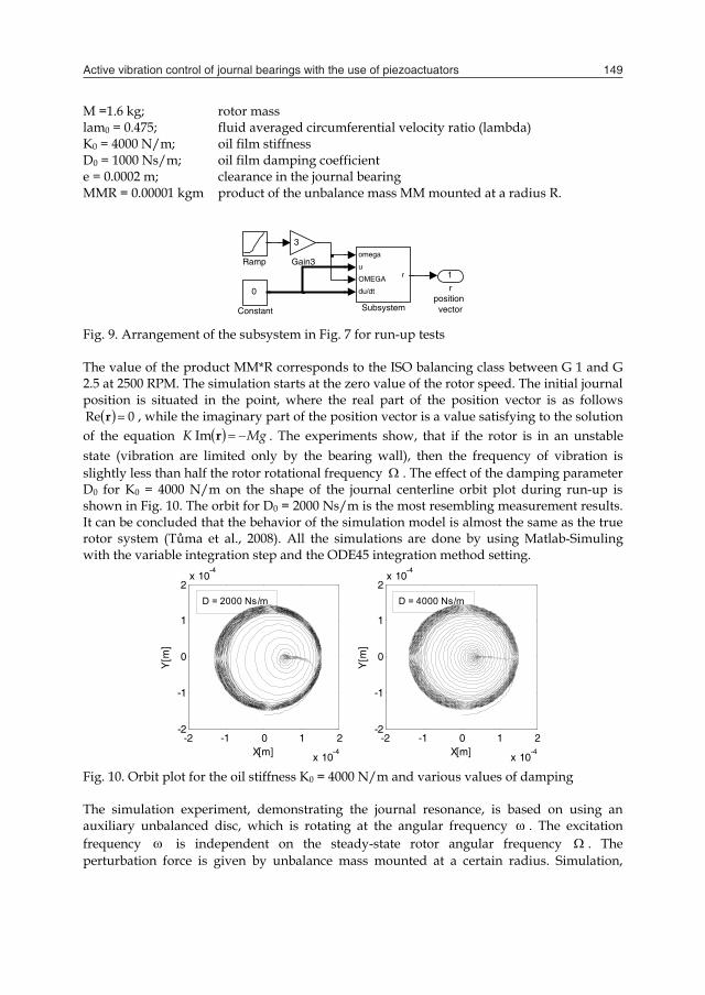
M =1.6 kg; rotor mass lam0 = 0.475; fluid averaged circumferential velocity ratio (lambda) K0 = 4000 N/m; oil film stiffness D0 = 1000 Ns/m; oil film damping coefficient e = 0.0002 m; clearance in the journal bearing MMR = 0.00001 kgm product of the unbalance mass MM mounted at a radius R.
Fig. 9. Arrangement of the subsystem in Fig. 7 for run-up tests The value of the product MM*R corresponds to the ISO balancing class between G 1 and G 2.5 at 2500 RPM. The simulation starts at the zero value of the rotor speed. The initial journal position is situated in the point, where the real part of the position vector is as follows
0Re r , while the imaginary part of the position vector is a value satisfying to the solution of the equation MgK rIm . The experiments show, that if the rotor is in an unstable state (vibration are limited only by the bearing wall), then the frequency of vibration is slightly less than half the rotor rotational frequency . The effect of the damping parameter D0 for K0 = 4000 N/m on the shape of the journal centerline orbit plot during run-up is shown in Fig. 10. The orbit for D0 = 2000 Ns/m is the most resembling measurement results. It can be concluded that the behavior of the simulation model is almost the same as the true rotor system (Tůma et al., 2008). All the simulations are done by using Matlab-Simuling with the variable integration step and the ODE45 integration method setting.
Fig. 10. Orbit plot for the oil stiffness K0 = 4000 N/m and various values of damping The simulation experiment, demonstrating the journal resonance, is based on using an auxiliary unbalanced disc, which is rotating at the angular frequency . The excitation frequency is independent on the steady-state rotor angular frequency . The perturbation force is given by unbalance mass mounted at a certain radius. Simulation,
-2 -1 0 1 2
x 10-4
-2
-1
0
1
2x 10
-4
X[m]
Y[m
]
-2 -1 0 1 2
x 10-4
-2
-1
0
1
2x 10
-4
X[m]
Y[m
]
D = 2000 Ns/m D = 4000 Ns/m
1r
position vector
omega
u OMEGA du/dt
r
Subsystem
Ramp
3
Gain3
0
Constant
Active vibration control of journal bearings with the use of piezoactuators 149
Fig. 7. Matlab-Simulink model of a rotor motion in a plane perpendicular to its axis
Fig. 8. Effect of the position vector magnitude related to the bearing clearance on the relative value K, D, (Lambda) related to the initial value ( 0abs r ) As was stated before the numeric solution of the journal equation of motion is obtained by using Matlab-Simulink. As the rotor system stability margin depends on the oil film stiffness and rotor mass, the first step is to estimate stiffness K . This task is not an easy problem due to the rotor static load by the gravity force and the dependence of the oil film stiffness on the rotor eccentricity. The second problem is estimation of damping D , which predefines the rotor system vibration mode at the angular frequency, which is approximately equal to the half of the rotor angular frequency. The way, how to analyze effect of oil stiffness on the rotor behavior, is to test the rotor response to the RPM run-up. The arrangement of the Simulink model is shown in Fig. 7. The agreement between the mentioned experiment and the simulation model is reached for the following values of the parameters
1
rposition
vector
i * D * r * lam * OMEGA
MMR*u^2
Unbalance
-i*M*9.81
Static force
mr*u^2
Non-synch force|.|
Mag-Angleto Complex2
|.|
Mag-Angleto Complex1
K * r
1s
Integrator1
dx/dt x
Integrator 2
dx/dt x
Integrator 1
1s
Integrator
i
Gain1
1/M
Gain
r
D
K
lamD, K, lam
D * r * lam
D * dr/dt
Add
4
du/dt
3
uposition
vector
2
OMEGA
1
omega
0 0.2 0.4 0.6 0.8 11
10
100
1000
abs(r) / e
K /
K0,
D /
D0
0 0.2 0.4 0.6 0.8 10.4
0.5
0.6
0.7
0.8
0.9
1
abs(r) / e
lam
/ la
m0
K / K0D / D0
M =1.6 kg; rotor mass lam0 = 0.475; fluid averaged circumferential velocity ratio (lambda) K0 = 4000 N/m; oil film stiffness D0 = 1000 Ns/m; oil film damping coefficient e = 0.0002 m; clearance in the journal bearing MMR = 0.00001 kgm product of the unbalance mass MM mounted at a radius R.
Fig. 9. Arrangement of the subsystem in Fig. 7 for run-up tests The value of the product MM*R corresponds to the ISO balancing class between G 1 and G 2.5 at 2500 RPM. The simulation starts at the zero value of the rotor speed. The initial journal position is situated in the point, where the real part of the position vector is as follows
0Re r , while the imaginary part of the position vector is a value satisfying to the solution of the equation MgK rIm . The experiments show, that if the rotor is in an unstable state (vibration are limited only by the bearing wall), then the frequency of vibration is slightly less than half the rotor rotational frequency . The effect of the damping parameter D0 for K0 = 4000 N/m on the shape of the journal centerline orbit plot during run-up is shown in Fig. 10. The orbit for D0 = 2000 Ns/m is the most resembling measurement results. It can be concluded that the behavior of the simulation model is almost the same as the true rotor system (Tůma et al., 2008). All the simulations are done by using Matlab-Simuling with the variable integration step and the ODE45 integration method setting.
Fig. 10. Orbit plot for the oil stiffness K0 = 4000 N/m and various values of damping The simulation experiment, demonstrating the journal resonance, is based on using an auxiliary unbalanced disc, which is rotating at the angular frequency . The excitation frequency is independent on the steady-state rotor angular frequency . The perturbation force is given by unbalance mass mounted at a certain radius. Simulation,
-2 -1 0 1 2
x 10-4
-2
-1
0
1
2x 10
-4
X[m]
Y[m
]
-2 -1 0 1 2
x 10-4
-2
-1
0
1
2x 10
-4
X[m]
Y[m
]
D = 2000 Ns/m D = 4000 Ns/m
1r
position vector
omega
u OMEGA du/dt
r
Subsystem
Ramp
3
Gain3
0
Constant

Engineering the Future150
which is described in this chapter, is focused on the kinematic non-synchronous rotor excitation to prove the effect of the movement of the bushing on the movement of the rotor shaft. Instead of the periodic force, the periodic displacement of bushing is assumed. Unbalance mass produces a perturbation force, which amplitude is proportional to the square of the angular frequency. The simulation of the kinematic perturbation will suppose constant amplitude of the bushing displacement. The arrangement of the Simulink model is shown in Fig. 11.
Fig. 11. Arrangement of the subsystem in figure 4 for kinematic perturbation tests
Fig. 12. Time histories of the rotor and kinematic perturbation RPM and the response of the supporting ring kinematic perturbation to the rotor displacement Simulation of the kinematic perturbation is divided into two stages. At first the rotor rotational speed reaches the steady state rotation at the 1200 RPM and then the perturbation displacement of the supporting ring starts to run-up from the zero frequency zero to
0 1 2 3 4 5 6 7 8 9 100
400800
12001600
Time [s]
RP
M
0 1 2 3 4 5 6 7 8 9 100
400800
12001600
Time [s]
rpm
0 1 2 3 4 5 6 7 8 9 10-2
0
2x 10
-4
Time [s]
Re(
r), I
m(r)
[m
]
Rotor RPM
Kinematic preturbation rpm
resonance
1
rposition
vector
u^2
squareomega
u OMEGA du/dt
r
Subsystem
Ramp1
|.|
Mag-Angleto Complex2 1
s
Integrator
20
Gain2
0.4
Gain1
1-exp(-1.5*u)
First Order System
x dx/dt
Differentiation
3e-5
Constant
0
Constant
Clock1
apExvelunpe Th800syntha
4.
A reshyencleoriprepieV. 300LVpufrethe
Fig Shcursupwe
proximately 1100xcept of the imagilocities are set to
nknown initial rturbation rotatio
he simulation resu0 RPM of the bnchronous perturan half the rotor r
Test Stand for
technical drawinspectively. The
ydrodynamic joursure sealing of o
earance in bearingiented in verticaeloaded open-looezoactuator types The pushing for0 N. The piezoac
VPZT piezoactuatulling force is up tequency motor 3 e shaft is decoupl
g. 13. Test stand c
haft movement is rrent and electrpplied by the firmere used at the be
0 RPM. The rotorinary part of the o zero to avoid conditions at t
on starts after elap
ults are shown inbushing perturbarbation results inrotational speed (
r Research of A
ng and a photo test stand consi
rnal bearings. Beaoil inlet and at thg casing. Bearingl and horizontalop LVPZT piezoas require a low vrce produced by ctuator travel rantor of the P-844.6to 700 N in contrthrough an elast
led from motor an
cross section
measured by tworical capacitive m Brüel & Kjær, aeginning of tests
r rotational speed rotor initial posithe problem wit
the non-zero inpsing 3 seconds f
n Fig. 12. As is evation rotational sn resonance at the(600 RPM).
Active Vibratio
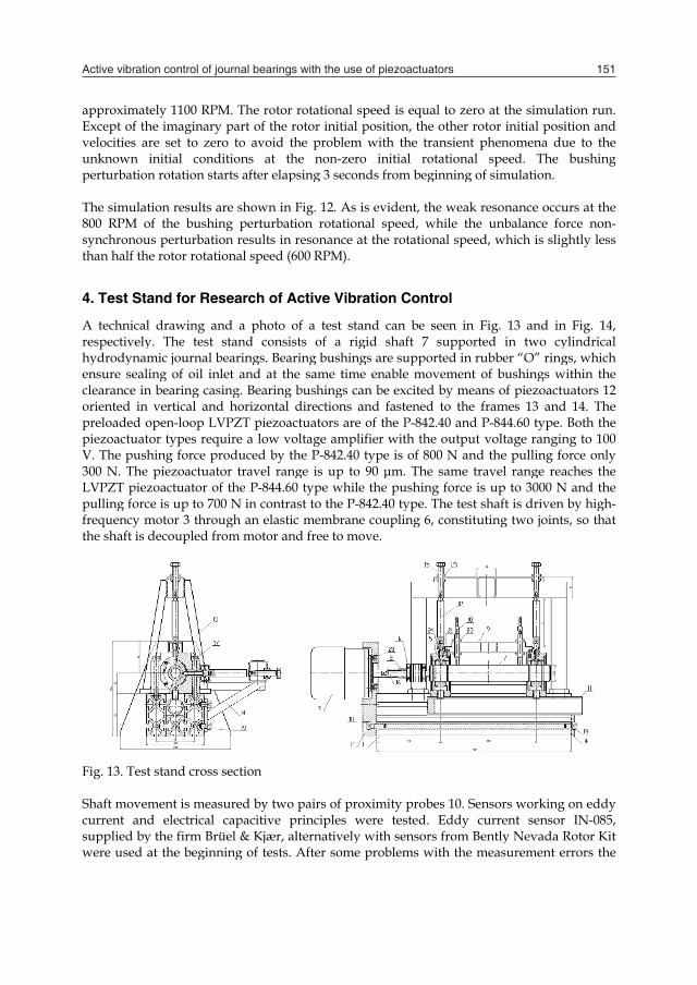
of a test stand ists of a rigid aring bushings arhe same time enag bushings can be directions and actuators are of thvoltage amplifier the P-842.40 typenge is up to 90 μ60 type while therast to the P-842.4tic membrane cound free to move.
o pairs of proximprinciples were alternatively with. After some prob
d is equal to zeroition, the other roth the transient pnitial rotational from beginning o
vident, the weak rspeed, while thee rotational speed
on Control
can be seen in Fshaft 7 support
re supported in ruable movement oe excited by meanfastened to the fhe P-842.40 and P with the output e is of 800 N andμm. The same tre pushing force is40 type. The test supling 6, constitu
mity probes 10. Sen tested. Eddy ch sensors from Beblems with the m
o at the simulatiootor initial positiophenomena due
speed. The buf simulation.
resonance occurs unbalance forced, which is slight
Fig. 13 and in Fted in two cylinubber “O” rings, of bushings withns of piezoactuatframes 13 and 1P-844.60 type. Bo voltage ranging
d the pulling forcravel range reachs up to 3000 N anshaft is driven by
uting two joints, s
nsors working oncurrent sensor Iently Nevada Ro
measurement erro
on run. on and to the
ushing
s at the e non-tly less
Fig. 14, ndrical which hin the tors 12 4. The
oth the to 100 ce only hes the nd the
y high-so that
n eddy N-085, tor Kit ors the
Active vibration control of journal bearings with the use of piezoactuators 151
which is described in this chapter, is focused on the kinematic non-synchronous rotor excitation to prove the effect of the movement of the bushing on the movement of the rotor shaft. Instead of the periodic force, the periodic displacement of bushing is assumed. Unbalance mass produces a perturbation force, which amplitude is proportional to the square of the angular frequency. The simulation of the kinematic perturbation will suppose constant amplitude of the bushing displacement. The arrangement of the Simulink model is shown in Fig. 11.
Fig. 11. Arrangement of the subsystem in figure 4 for kinematic perturbation tests
Fig. 12. Time histories of the rotor and kinematic perturbation RPM and the response of the supporting ring kinematic perturbation to the rotor displacement Simulation of the kinematic perturbation is divided into two stages. At first the rotor rotational speed reaches the steady state rotation at the 1200 RPM and then the perturbation displacement of the supporting ring starts to run-up from the zero frequency zero to
0 1 2 3 4 5 6 7 8 9 100
400800
12001600
Time [s]
RP
M
0 1 2 3 4 5 6 7 8 9 100
400800
12001600
Time [s]
rpm
0 1 2 3 4 5 6 7 8 9 10-2
0
2x 10
-4
Time [s]
Re(
r), I
m(r)
[m
]
Rotor RPM
Kinematic preturbation rpm
resonance
1
rposition
vector
u^2
squareomega
u OMEGA du/dt
r
Subsystem
Ramp1
|.|
Mag-Angleto Complex2 1
s
Integrator
20
Gain2
0.4
Gain1
1-exp(-1.5*u)
First Order System
x dx/dt
Differentiation
3e-5
Constant
0
Constant
Clock1
apExvelunpe Th800syntha
4.
A reshyencleoriprepieV. 300LVpufrethe
Fig Shcursupwe
proximately 1100xcept of the imagilocities are set to
nknown initial rturbation rotatio
he simulation resu0 RPM of the bnchronous perturan half the rotor r
Test Stand for
technical drawinspectively. The
ydrodynamic joursure sealing of o
earance in bearingiented in verticaeloaded open-looezoactuator types The pushing for0 N. The piezoac
VPZT piezoactuatulling force is up tequency motor 3 e shaft is decoupl
g. 13. Test stand c
haft movement is rrent and electrpplied by the firmere used at the be
0 RPM. The rotorinary part of the o zero to avoid conditions at t
on starts after elap
ults are shown inbushing perturbarbation results inrotational speed (
r Research of A
ng and a photo test stand consi
rnal bearings. Beaoil inlet and at thg casing. Bearingl and horizontalop LVPZT piezoas require a low vrce produced by ctuator travel rantor of the P-844.6to 700 N in contrthrough an elast
led from motor an
cross section
measured by tworical capacitive m Brüel & Kjær, aeginning of tests
r rotational speed rotor initial posithe problem wit
the non-zero inpsing 3 seconds f
n Fig. 12. As is evation rotational sn resonance at the(600 RPM).
Active Vibratio
of a test stand ists of a rigid aring bushings arhe same time enag bushings can be directions and actuators are of thvoltage amplifier the P-842.40 typenge is up to 90 μ60 type while therast to the P-842.4tic membrane cound free to move.
o pairs of proximprinciples were alternatively with. After some prob
d is equal to zeroition, the other roth the transient pnitial rotational from beginning o
vident, the weak rspeed, while thee rotational speed
on Control
can be seen in Fshaft 7 support
re supported in ruable movement oe excited by meanfastened to the fhe P-842.40 and P with the output e is of 800 N andμm. The same tre pushing force is40 type. The test supling 6, constitu
mity probes 10. Sen tested. Eddy ch sensors from Beblems with the m
o at the simulatiootor initial positiophenomena due
speed. The buf simulation.
resonance occurs unbalance forced, which is slight
Fig. 13 and in Fted in two cylinubber “O” rings, of bushings withns of piezoactuatframes 13 and 1P-844.60 type. Bo voltage ranging
d the pulling forcravel range reachs up to 3000 N anshaft is driven by
uting two joints, s
nsors working oncurrent sensor Iently Nevada Ro
measurement erro
on run. on and to the
ushing
s at the e non-tly less
Fig. 14, ndrical which hin the tors 12 4. The
oth the to 100 ce only hes the nd the
y high-so that
n eddy N-085, tor Kit ors the

Engineering the Future152
capIt imai.e
Fig
5.
Wh • • •
5.1TobeaHylubbeahyinsmo4 3wa
5.2Thabllooaxe
pacitive sensor cais possible to puass. However, low. with hollow sha
g. 14. Test stand f
Operation with
hen putting the te
choice of lubricameasurement acmounting of piethe accuracy of
1 Lubrication o reach the maximaring clearance toydraulic oil of thebricant was thenaring of the OL
ydraulic oil enabstability onset atotor maximum no300 RPM. All testas not preheated d
2 Measurement ahe first measuremly differing fromoked for in the ues, the oil pump
apaNCDT CS05, ut one or two diswest stability limaft without discs.
for research of act
hout Active Vib
est stand into ope
ating oil determinccuracy of shaft pezoactuators to avmicrometers.
mum motor speeo 90 μm with sime VG 32 class (ki
n substituted by L-P03 type (VG10bled to reach the the same valueominal rotationalts were undertakduring tests.
accuracy of shaments showed them a circle or an euniformity of mo and the interfer
supplied by the Mscs on the shaft,
mit should be ach The test stand wa
tive vibration con
bration Contro
eration, we met th
ning bearing frictposition void torsional loa
ed higher than 6multaneous decrea
nematic viscositybearing special 0, kinematic vise maximum rota
e of RPM. The bel speed 23 600 RP
ken at ambient te
aft position e shape of the rotellipse. To explaotor rotation, therence of the prox
Micro Epsilon cothus increasing b
hieved with the mas designed for sp
ntrol of journal be
ol
hese problems
tion losses
ading and enable
6 000 RPM it wasase of the calculaty of up to 32 mmoil for the high-cosity 2.5 to 4 mational speed ofearing special oiPM while the insemperature about
tor centerline trajin this phenome
e misalignment oximity probe outp
ompany, were insbearing load and
minimum bearingpeeds up to 23 000
earings
e adjusting positio
s necessary to inted rotor stability
m2/s at 40 °C) use-speed grinder smm2/s at 40 °Cf 16 000 RPM anil enabled to reatability onset start 20 °C. Lubricat
ectory (orbit) conenon, the reasonsof the motor andput signals. To a
stalled. d rotor g load, 0 rpm.
on at
ncrease y limit. ed as a pindle
C). The nd the ach the rted at ing oil
nsider-s were d rotor achieve
perfect decoupling of the test shaft from driving motor, another flexible coupling was installed between original coupling and the shaft. The rotation uniformity is not as smooth as when a DC motor is used. The interference between signals causes an error below 1 μm in measurements. Inspection of shaft geometrical deviations as is a non-circularity showed that this deviation is less than 1 μm as well. Finally it was proved, that the non-homogeneity of the rotor material magnetic and electric conductivity properties is the main source of the proximity probe periodical error. The error signal is repeated synchronously with rotor rotation. The same material is passing-by below the tip of the second proximity probe after one quarter of the rotor revolution; therefore a phase shift of the period quarter may be discovered. The peak-to-peak value of the regular periodic error reaches 11 μm. The spectrum of the measurement periodic error is composed from harmonics of the rotor rotational frequency. Periodic error for two different shafts is shown in Fig. 15.
Original hollow shaft (1 sensor) Rigid shaft (2 sensors)
Fig. 15. Regular error of proximity probe as a function of rotation angle The dependence of the proximity probe regular error on the rotation angle can be approximated by a sum of trigonometric functions differing in the number of waves. The reduction of the proximity probe error by subtraction of the error signal requires a tacho pulses measurement and prediction of the rotational angle.
Fig. 16. Frequency spectrum of the filtered and unfiltered output signal of the sensor based on electrical capacity (capaNCDT CS05) As was mentioned before, it is better to use sensors, which are based on measurements of electrical capacity. The output signal does not contain any low harmonic of the rotational frequency but some high frequency components due to demodulation of electric signals corrupt the measured signal. The analog RC-filter is required. The effect of the RC-filter on the frequency spectrum of the measured signal is shown in Fig. 16.
-15
0
15
0 1 2 3 4
µm
Nominal Revolution [-]
-8
-4
0
4
0 1 2 3 4
µm
Nominal Revolution [-]
0,000001
0,000010
0,000100
0,001000
0,010000
10 100 1000 10000
RM
S m
m
Frequency [Hz]
unfiltered
filtered

Active vibration control of journal bearings with the use of piezoactuators 153
capIt imai.e
Fig
5.
Wh • • •
5.1TobeaHylubbeahyinsmo4 3wa
5.2Thabllooaxe
pacitive sensor cais possible to puass. However, low. with hollow sha
g. 14. Test stand f
Operation with
hen putting the te
choice of lubricameasurement acmounting of piethe accuracy of
1 Lubrication o reach the maximaring clearance toydraulic oil of thebricant was thenaring of the OL
ydraulic oil enabstability onset atotor maximum no300 RPM. All testas not preheated d
2 Measurement ahe first measuremly differing fromoked for in the ues, the oil pump
apaNCDT CS05, ut one or two diswest stability limaft without discs.
for research of act
hout Active Vib
est stand into ope
ating oil determinccuracy of shaft pezoactuators to avmicrometers.
mum motor speeo 90 μm with sime VG 32 class (ki
n substituted by L-P03 type (VG10bled to reach the the same valueominal rotationalts were undertakduring tests.
accuracy of shaments showed them a circle or an euniformity of mo and the interfer
supplied by the Mscs on the shaft,
mit should be ach The test stand wa
tive vibration con
bration Contro
eration, we met th
ning bearing frictposition void torsional loa
ed higher than 6multaneous decrea
nematic viscositybearing special 0, kinematic vise maximum rota
e of RPM. The bel speed 23 600 RP
ken at ambient te
aft position e shape of the rotellipse. To explaotor rotation, therence of the prox
Micro Epsilon cothus increasing b
hieved with the mas designed for sp
ntrol of journal be
ol
hese problems
tion losses
ading and enable
6 000 RPM it wasase of the calculaty of up to 32 mmoil for the high-cosity 2.5 to 4 mational speed ofearing special oiPM while the insemperature about
tor centerline trajin this phenome
e misalignment oximity probe outp
ompany, were insbearing load and
minimum bearingpeeds up to 23 000
earings
e adjusting positio
s necessary to inted rotor stability
m2/s at 40 °C) use-speed grinder smm2/s at 40 °Cf 16 000 RPM anil enabled to reatability onset start 20 °C. Lubricat
ectory (orbit) conenon, the reasonsof the motor andput signals. To a
stalled. d rotor g load, 0 rpm.
on at
ncrease y limit. ed as a pindle
C). The nd the ach the rted at ing oil
nsider-s were d rotor achieve
perfect decoupling of the test shaft from driving motor, another flexible coupling was installed between original coupling and the shaft. The rotation uniformity is not as smooth as when a DC motor is used. The interference between signals causes an error below 1 μm in measurements. Inspection of shaft geometrical deviations as is a non-circularity showed that this deviation is less than 1 μm as well. Finally it was proved, that the non-homogeneity of the rotor material magnetic and electric conductivity properties is the main source of the proximity probe periodical error. The error signal is repeated synchronously with rotor rotation. The same material is passing-by below the tip of the second proximity probe after one quarter of the rotor revolution; therefore a phase shift of the period quarter may be discovered. The peak-to-peak value of the regular periodic error reaches 11 μm. The spectrum of the measurement periodic error is composed from harmonics of the rotor rotational frequency. Periodic error for two different shafts is shown in Fig. 15.
Original hollow shaft (1 sensor) Rigid shaft (2 sensors)
Fig. 15. Regular error of proximity probe as a function of rotation angle The dependence of the proximity probe regular error on the rotation angle can be approximated by a sum of trigonometric functions differing in the number of waves. The reduction of the proximity probe error by subtraction of the error signal requires a tacho pulses measurement and prediction of the rotational angle.
Fig. 16. Frequency spectrum of the filtered and unfiltered output signal of the sensor based on electrical capacity (capaNCDT CS05) As was mentioned before, it is better to use sensors, which are based on measurements of electrical capacity. The output signal does not contain any low harmonic of the rotational frequency but some high frequency components due to demodulation of electric signals corrupt the measured signal. The analog RC-filter is required. The effect of the RC-filter on the frequency spectrum of the measured signal is shown in Fig. 16.
-15
0
15
0 1 2 3 4
µm
Nominal Revolution [-]
-8
-4
0
4
0 1 2 3 4
µm
Nominal Revolution [-]
0,000001
0,000010
0,000100
0,001000
0,010000
10 100 1000 10000
RM
S m
m
Frequency [Hz]
unfiltered
filtered

Engineering the Future154
The measurement of the shaft displacement with the use of the eddy-current sensor in the horizontal direction (X) is shown in Fig. 17 on the right side. The rotor increased the rotational speed at the rate of 7000 RPM per minute. The sampling frequency was set to 2048 Hz. The measurement with the use of the capacitive sensor is shown in the same Fig. 17 on the left side. It should be mentioned that the output signal of the sensor of the capacitive type was filtered with the use of the Butterworth filter, order 4, cut-off frequency 200 Hz.
Fig. 17. Measurement of the shaft horizontal displacement using the sensor a sensor based on electrical capacity (capaNCDT CS05) and the sensor based on the eddy current (IN-085) The measurements of the shaft displacement during run up proceeded with extremely low viscous oil VG10 without preheating. It is technically impossible to increase the rotor rotational speed smoothly from 0 RPM. Rotor starts at the speed of 230 RPM and then continuously increases up to the onset of instability. The journal movement begins at the bottom of the bearing sleeve and with increasing speed it moves up in direction of rotation. At the level of the sleeve centre the journal starts to move towards the bearing centre. With infinite speed or zero load the journal centre coincidences with bearing centre, which is generally unstable position in circular bearing. The instability onset is at about 4 300 RPM. 5.3 Mounting of Piezoactuators Choice of the piezoactuator type was verified by measurement of the dependence of acting force on the open-loop piezoactuator travel. Force of 500 N is sufficient to overcome flexibility of the sealing “O” rings. Flexible tip was used to attach the piezoactuator to the bushing rod and the frame structure for compensation of misalignment and possible bending load. The test stand instrumentation allows active vibration control only in the journal bearing at the opposite side to the driving motor. Before beginning the operational tests, the initial position of the piezoactuators has to be adjusted in the middle position of the operating travel range. This position corresponds to half the output voltage of the controller, the full range of which is equal to 12V. A screw at a holder is tightened in this position. The range of the shaft displacement for the full scale of the controller output voltage is shown in Fig. 18 for the horizontal (Axis X) and vertical (Axis Y) directions of the shaft displacement.
Fig. 18. Effect of the amplifier input voltage on the shaft position change in the horizontal and vertical direction
6. Control System
As was mentioned earlier, the signal from the proximity probes is connected to the dSpace signal processor. The output of the signal processor is connected to the input of the amplifier that powers the piezoactuator. The electronic feedback (see Fig. 19) in the below presented experiments was of the proportional controller type. Although improved dynamic properties of the control loop require adding a derivative component, the noisy signal produced by the proximity probes is the reason why the derivative feedback was not used (Víteček, et al., 2009). Even if the sensors based on the electrical capacity principle have a smaller error than the eddy current sensors, the active vibration control has been tested with sensors based on eddy currents.
Fig. 19. Active vibration control system The time history of the shaft rotational speed in RPM for the tests under active control (ON) and without active control (OFF) is shown in Fig. 20. For the oil of the VG10 type the onset of instability starts at 4 300 RPM. Because the piezoactuator travel range cannot cover the change of the shaft position from the very beginning up to the level of the bushing centre position, the active vibration control is switched ON when the shaft lifts up into the stabilized position, which corresponds approximately to 3 000 RPM. Due to the measurement error the controller out voltage starts to oscillate with a limited magnitude. As is clear from Fig. 21, if the active control is switched ON during the RPM run-up the onset of instability is changed to 7 300 RPM. The result of measurements at half the open-loop gain
-740-730-720-710-700-690-680-670-660-650-640
0 25 50 75 100Time [s]
mic
rom
eter
MAX
MIN
0 V 0 V
12 V
step 2 V
Axis X
-760-740-720-700-680-660-640-620-600
0 25 50 75 100Time [s]
mic
rom
eter
Lower stop
Upper stop
0 V
0 V12 V
12 V
Axis Y
Load
+
Journal position
Set point
Piezoelectricactuators
Rotor system
+- Controller dSpace
Proximity probes +
Amplifier
Bushing
0 to 100 V 0 to 12 V

Active vibration control of journal bearings with the use of piezoactuators 155
The measurement of the shaft displacement with the use of the eddy-current sensor in the horizontal direction (X) is shown in Fig. 17 on the right side. The rotor increased the rotational speed at the rate of 7000 RPM per minute. The sampling frequency was set to 2048 Hz. The measurement with the use of the capacitive sensor is shown in the same Fig. 17 on the left side. It should be mentioned that the output signal of the sensor of the capacitive type was filtered with the use of the Butterworth filter, order 4, cut-off frequency 200 Hz.
Fig. 17. Measurement of the shaft horizontal displacement using the sensor a sensor based on electrical capacity (capaNCDT CS05) and the sensor based on the eddy current (IN-085) The measurements of the shaft displacement during run up proceeded with extremely low viscous oil VG10 without preheating. It is technically impossible to increase the rotor rotational speed smoothly from 0 RPM. Rotor starts at the speed of 230 RPM and then continuously increases up to the onset of instability. The journal movement begins at the bottom of the bearing sleeve and with increasing speed it moves up in direction of rotation. At the level of the sleeve centre the journal starts to move towards the bearing centre. With infinite speed or zero load the journal centre coincidences with bearing centre, which is generally unstable position in circular bearing. The instability onset is at about 4 300 RPM. 5.3 Mounting of Piezoactuators Choice of the piezoactuator type was verified by measurement of the dependence of acting force on the open-loop piezoactuator travel. Force of 500 N is sufficient to overcome flexibility of the sealing “O” rings. Flexible tip was used to attach the piezoactuator to the bushing rod and the frame structure for compensation of misalignment and possible bending load. The test stand instrumentation allows active vibration control only in the journal bearing at the opposite side to the driving motor. Before beginning the operational tests, the initial position of the piezoactuators has to be adjusted in the middle position of the operating travel range. This position corresponds to half the output voltage of the controller, the full range of which is equal to 12V. A screw at a holder is tightened in this position. The range of the shaft displacement for the full scale of the controller output voltage is shown in Fig. 18 for the horizontal (Axis X) and vertical (Axis Y) directions of the shaft displacement.
Fig. 18. Effect of the amplifier input voltage on the shaft position change in the horizontal and vertical direction
6. Control System
As was mentioned earlier, the signal from the proximity probes is connected to the dSpace signal processor. The output of the signal processor is connected to the input of the amplifier that powers the piezoactuator. The electronic feedback (see Fig. 19) in the below presented experiments was of the proportional controller type. Although improved dynamic properties of the control loop require adding a derivative component, the noisy signal produced by the proximity probes is the reason why the derivative feedback was not used (Víteček, et al., 2009). Even if the sensors based on the electrical capacity principle have a smaller error than the eddy current sensors, the active vibration control has been tested with sensors based on eddy currents.
Fig. 19. Active vibration control system The time history of the shaft rotational speed in RPM for the tests under active control (ON) and without active control (OFF) is shown in Fig. 20. For the oil of the VG10 type the onset of instability starts at 4 300 RPM. Because the piezoactuator travel range cannot cover the change of the shaft position from the very beginning up to the level of the bushing centre position, the active vibration control is switched ON when the shaft lifts up into the stabilized position, which corresponds approximately to 3 000 RPM. Due to the measurement error the controller out voltage starts to oscillate with a limited magnitude. As is clear from Fig. 21, if the active control is switched ON during the RPM run-up the onset of instability is changed to 7 300 RPM. The result of measurements at half the open-loop gain
-740-730-720-710-700-690-680-670-660-650-640
0 25 50 75 100Time [s]
mic
rom
eter
MAX
MIN
0 V 0 V
12 V
step 2 V
Axis X
-760-740-720-700-680-660-640-620-600
0 25 50 75 100Time [s]
mic
rom
eter
Lower stop
Upper stop
0 V
0 V12 V
12 V
Axis Y
Load
+
Journal position
Set point
Piezoelectricactuators
Rotor system
+- Controller dSpace
Proximity probes +
Amplifier
Bushing
0 to 100 V 0 to 12 V

Engineering the Future156
(50%) is shown in the middle part of Fig. 21. The onset of instability occurs at about 6 200 RPM. The active vibration control is naturally immediately switched OFF after starting the unstable vibration at the subharmonic frequency of the shaft rotation frequency. The output of the signal processor is saturated on the full voltage range from 0 to 12 V.
Fig. 20. Time history of the rotor rotation speed when the active vibration control is ON and OFF
Fig. 21. Time history of the rotor displacements in horizontal and vertical direction and control signals for piezoactuators when the active vibration control is ON and OFF As it is demonstrated in Fig. 21 the active vibration control significantly extends the range of operating rotational speed by about 3 000 RPM in comparison with the operating range
without the active vibration control. The electronic feedback is clearly seen as a complementary way to the traditional journal bearing design modifications and other tools, which prevent instability or shift the rotor instability onset to higher rotational speed. Provided that the perturbation force is zero the Laplace transfer function relating the displacement of the bushing to the displacement of the shaft is given by
)(
)(2
jDKDsMsjDKDs
sssGPlant u
r (14)
Assuming that the proportional controller set point is equal to zero and its gain equals to
PK the open-loop transfer function is as follows
)(
)(2
jDKDsMsjDKDs
KsG Po (15)
2)()(
MjDKDjjDKDjKjG Po (16)
For the stability margin the open-loop frequency transfer function is equal to 10 G . The frequency of the steady-state vibration at the stability margin is given by . If the feedback gain PK is positive then the maximal rotational speed MAX of the rotor is greater than the critical rotational speed without any control (12). Increasing is given by the formula .1 PCRITMAX K (17) The control system does not stabilize the behavior of the journal bearing by changing the position of the bearing bushing, but by changing force that acts on this bushing. Displacement of the bushing depends on the stiffness of its connection with the bearing body through rubber seal rings. The range of the rotor stable speed range is limited by the travel range of piezoactuators and measurement errors of the proximity probes.
7. Conclusion
The lumped parameter model of the journal motion inside the hydrodynamic bearing is based on the concept developed by Muszynska. According to Muszynska approximation, the bearing forces can be modeled by a spring and damper system. This system is rotating at the angular velocity, which is a constant fraction of the rotor rotational speed. The equation of motion contains the complex vector and parameters. The main goal of the simulation study was to verify the model principle by comparing simulation results with results of experiments, which are described in many papers, namely the instability of motion and the vibration mode at the non-synchronous perturbation. The simulation of the rotor system using Simulink confirms the agreement between Muszynska’s model and experiments. Test stand for experimental investigation of possibilities to affect behavior of the rotor supported in sliding bearings by external excitation was designed and manufactured.

Active vibration control of journal bearings with the use of piezoactuators 157
(50%) is shown in the middle part of Fig. 21. The onset of instability occurs at about 6 200 RPM. The active vibration control is naturally immediately switched OFF after starting the unstable vibration at the subharmonic frequency of the shaft rotation frequency. The output of the signal processor is saturated on the full voltage range from 0 to 12 V.
Fig. 20. Time history of the rotor rotation speed when the active vibration control is ON and OFF
Fig. 21. Time history of the rotor displacements in horizontal and vertical direction and control signals for piezoactuators when the active vibration control is ON and OFF As it is demonstrated in Fig. 21 the active vibration control significantly extends the range of operating rotational speed by about 3 000 RPM in comparison with the operating range
without the active vibration control. The electronic feedback is clearly seen as a complementary way to the traditional journal bearing design modifications and other tools, which prevent instability or shift the rotor instability onset to higher rotational speed. Provided that the perturbation force is zero the Laplace transfer function relating the displacement of the bushing to the displacement of the shaft is given by
)(
)(2
jDKDsMsjDKDs
sssGPlant u
r (14)
Assuming that the proportional controller set point is equal to zero and its gain equals to
PK the open-loop transfer function is as follows
)(
)(2
jDKDsMsjDKDs
KsG Po (15)
2)()(
MjDKDjjDKDjKjG Po (16)
For the stability margin the open-loop frequency transfer function is equal to 10 G . The frequency of the steady-state vibration at the stability margin is given by . If the feedback gain PK is positive then the maximal rotational speed MAX of the rotor is greater than the critical rotational speed without any control (12). Increasing is given by the formula .1 PCRITMAX K (17) The control system does not stabilize the behavior of the journal bearing by changing the position of the bearing bushing, but by changing force that acts on this bushing. Displacement of the bushing depends on the stiffness of its connection with the bearing body through rubber seal rings. The range of the rotor stable speed range is limited by the travel range of piezoactuators and measurement errors of the proximity probes.
7. Conclusion
The lumped parameter model of the journal motion inside the hydrodynamic bearing is based on the concept developed by Muszynska. According to Muszynska approximation, the bearing forces can be modeled by a spring and damper system. This system is rotating at the angular velocity, which is a constant fraction of the rotor rotational speed. The equation of motion contains the complex vector and parameters. The main goal of the simulation study was to verify the model principle by comparing simulation results with results of experiments, which are described in many papers, namely the instability of motion and the vibration mode at the non-synchronous perturbation. The simulation of the rotor system using Simulink confirms the agreement between Muszynska’s model and experiments. Test stand for experimental investigation of possibilities to affect behavior of the rotor supported in sliding bearings by external excitation was designed and manufactured.

Engineering the Future158
The tests carried out showed some features, which had to be cleared before experiments with bearing bushing control could be started. Standard behavior of the rotor was achieved with low viscosity oil, with which the oil film had insufficient load capacity to shift journal centre into unstable position at the bearing centre. The proposed goal of the project was achieved by substantially increasing the onset of instability through controlled movement of only one bearing bushing. It seems, that there is a large potential for further improvements, which could lead to active control of behavior of high-speed rotors in real operating conditions.
8. References
Muszynska, A. (1986) Whirl and Whip – Rotor / Bearing Stability Problems. Journal of Sound and Vibration (1986) 110(3), pp 443-462.
Muszynska, A. (2005) Rotordynamics, Taylor & Francis Group, New York 2005, ISBN 0-8247-2399-6.
Bently, D.E. & Muszynska, A. (1989) Fluid-generated Instabilities of Rotors, Orbit, Volume 10, No. I, April, 1989.
Tondl, A. (1991) Quenching of self-excited vibrations. Academia, Prague 1991. Burns, R. (2001) Advanced control Engineering, Butterworth Heinemann, Oxford 2001. Carmignani, C. & Forte, P. & Rustighi, E. (2001) Active control of rotor vibrations by means
of piezoelectric atuators. Proc. DETC2001 18th Biennial Conference on Mechanical Vibration and Noise, Pittsburgh, Pennsylvania, 2001.
Rho, B-H, & Kim, K-W. (2002) The effect of active control on stability characteristics of hydrodynamic journal bearings with an axial groove. Proceedings of the Institution of Me-chanical Engineers, Part C: Journal of Mechanical Engineering Science, Volume 216, Number 9 / 2002, 2002, pp. 939-946.
Tůma, J. & Bilošová, A. & Šimek, J. & Svoboda, R. (2008) A simulation study of the rotor vibration. In: Dynamics of machines 2008. Prague, February 5-6, 2008, p. 1-8.
Tůma, J. & Klečka, R. & Škuta, J. & Šimek, J. (2009) A 3D model of the rigid rotor supported by journal bearing, In: 9th CONFERENCE on Active Vibration and Control Methods, Krakow, Poland, May 24 - 27, 2009.
Tůma, J. & Škuta, J. & Klečka, R. & Los, J. & Šimek, J. (2010) A laboratory test stand for active control of journal bearings. Proc. Colloquium Dynamics of Machines 2010, Inst. of Thermomechanics, Prague, February 2-3, 2010, pp. 95-100.
Šimek, J. & Tůma, J. & Škuta, J. & Klečka, R. (2010) Unorthodox behavior of a rigid rotor supported in sliding bearings. Proc. Colloquium Dynamics of Machines 2010, Inst. of Thermomechanics, Prague, February 2-3, 2010, pp. 85-90.
Víteček, A. & Tůma, J. & Vítečková, M. (2008) Stability of Rigid Rotor in Journal Bearing. Transactions of the VŠB – Technical University of Ostrava. Mechanical Series. No. 2, 2008, vol. LIV, article 1638, pp. 159-164.