active vibration control of two-mass exible system using
TRANSCRIPT
Active vibration control of two-massflexible system using parametric Jordan
form assignment
M. Schlegel, M.Goubej, J. Konigsmarkova ∗
∗University of West Bohemia, Pilsen, 30614 Czech Republic (e-mail:[email protected], [email protected], [email protected]).
Abstract: This paper deals with stage motion control system for scene manipulation duringtheater performance. Particular task of rope drum control is presented and solved. The systemexhibits an oscillatory dynamics due to the elasticity of the rope with a hanging load. Thegoal was to find a simple control strategy based on a common cascade PID structure which isavailable in most of the industrial AC drives. Formerly developed method of parametric Jordanform assignment was used to solve the problem and obtain simple tuning rules.
Keywords: Active vibration control, motion control, PID control, parametric Jordan formassignment, two-mass model, flexible system
1. INTRODUCTION
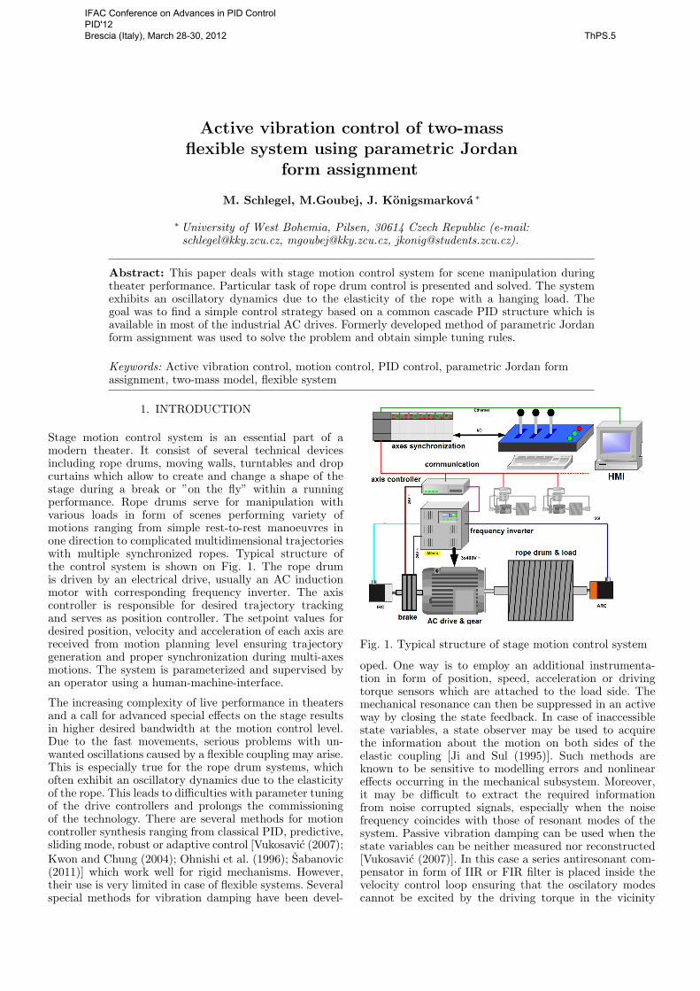
Stage motion control system is an essential part of amodern theater. It consist of several technical devicesincluding rope drums, moving walls, turntables and dropcurtains which allow to create and change a shape of thestage during a break or ”on the fly” within a runningperformance. Rope drums serve for manipulation withvarious loads in form of scenes performing variety ofmotions ranging from simple rest-to-rest manoeuvres inone direction to complicated multidimensional trajectorieswith multiple synchronized ropes. Typical structure ofthe control system is shown on Fig. 1. The rope drumis driven by an electrical drive, usually an AC inductionmotor with corresponding frequency inverter. The axiscontroller is responsible for desired trajectory trackingand serves as position controller. The setpoint values fordesired position, velocity and acceleration of each axis arereceived from motion planning level ensuring trajectorygeneration and proper synchronization during multi-axesmotions. The system is parameterized and supervised byan operator using a human-machine-interface.
The increasing complexity of live performance in theatersand a call for advanced special effects on the stage resultsin higher desired bandwidth at the motion control level.Due to the fast movements, serious problems with un-wanted oscillations caused by a flexible coupling may arise.This is especially true for the rope drum systems, whichoften exhibit an oscillatory dynamics due to the elasticityof the rope. This leads to difficulties with parameter tuningof the drive controllers and prolongs the commissioningof the technology. There are several methods for motioncontroller synthesis ranging from classical PID, predictive,sliding mode, robust or adaptive control [Vukosavic (2007);Kwon and Chung (2004); Ohnishi et al. (1996); Sabanovic(2011)] which work well for rigid mechanisms. However,their use is very limited in case of flexible systems. Severalspecial methods for vibration damping have been devel-
Fig. 1. Typical structure of stage motion control system
oped. One way is to employ an additional instrumenta-tion in form of position, speed, acceleration or drivingtorque sensors which are attached to the load side. Themechanical resonance can then be suppressed in an activeway by closing the state feedback. In case of inaccessiblestate variables, a state observer may be used to acquirethe information about the motion on both sides of theelastic coupling [Ji and Sul (1995)]. Such methods areknown to be sensitive to modelling errors and nonlineareffects occurring in the mechanical subsystem. Moreover,it may be difficult to extract the required informationfrom noise corrupted signals, especially when the noisefrequency coincides with those of resonant modes of thesystem. Passive vibration damping can be used when thestate variables can be neither measured nor reconstructed[Vukosavic (2007)]. In this case a series antiresonant com-pensator in form of IIR or FIR filter is placed inside thevelocity control loop ensuring that the oscilatory modescannot be excited by the driving torque in the vicinity
IFAC Conference on Advances in PID Control PID'12 Brescia (Italy), March 28-30, 2012 ThPS.5

Fig. 2. Simplified model of the rope drum system
of the resonant frequency. Alternatively, proper filter canshape the setpoint values for the motion controller in thefeedforward path [Goubej and Schlegel (2010)]. The maindisadvantage of passive damping approach is that the res-onant mode remains uncontrollable after the cancelationwith the series compensator and any outer disturbance willcause the undesirable oscillations.
Many modern methods for optimal controller synthesis(LQG, H2, H∞) generally produce high-order compen-sators which are difficult to implement due to their sen-sitivity to rounding and modelling errors. Only a numer-ical solution to the problem is often available and set ofcomplex mathematical routines is needed to obtain someresults. The parameter tuning is achieved by modifyingsome weighting functions without a clear physical meaningand several iterations may be needed to get a suitabledesign. There is a gap between the academic researchand industrial practice where the PID controller is stillprevailing. Therefore, our goal was to find a simple methodbased on partial pole placement technique for low-ordercompensator synthesis which may be used in most stan-dard industrial drives equipped with common cascadedPID control structure.
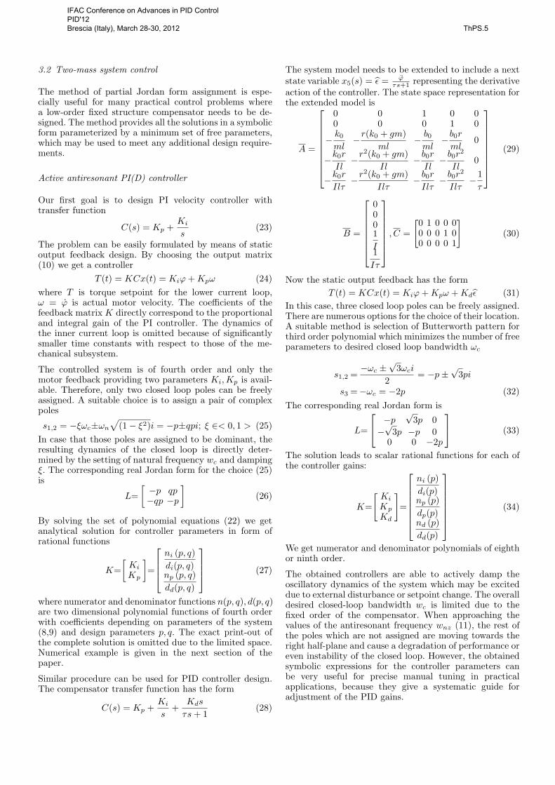
2. MATHEMATICAL MODEL OF THE ROPE DRUMSYSTEM
The system consists of rotational drum, flexible rope anda hanging load (Fig. 2). To obtain a finite-order modelsuitable for control law design, some simplifications haveto be made. We assume that the elastic rope with load canbe modelled as an mass-spring-damper system. The valuesof spring constant k and viscous damping coefficient b aregenerally time varying and they depend on the length ofthe rope according to Hooke’s law:
k =k0
l, b =
b0l
(1)
where k0 corresponds to the stiffness of the unit length ofthe rope and l is the actual length in dependence on drumposition ϕ
l = l0 − ϕr (2)
The equations of motion can be derived using the Newton-Euler method.
From the total torque Tt acting on the drum we get:
Tt = T − k(x− l)r − br(x− l) = Iϕ (3)
Sum of forces acting Ft on the load:
Ft = mg − k(x− l)− b(x− l) = mx (4)
Substituting from (1,2) we can write:
T − k0
l0 − ϕr(x− l0 + ϕr)r − br(x+ rϕ) = Iϕ (5)
mg − k0
l0 − ϕr(x− l0 + ϕr)− b(x+ rϕ) = mx (6)
By introducing state variables x = [x1 x2 x3 x4]T =[x ϕ x ϕ]T we get nonlinear state space representationin form:
x1 = x3
x2 = x4
x3 =− 1m
k0
l0 − rx2(x1 − l0 + rx2)− b
m(x3 + rx4) + g
x4 =−1I
k0
l0 − rx2(x1 − l0 + rx2)r − br
I(x3 + rx4) +
1IT
b=b0
l0 − rx2(7)
The only outputs available for measurement are motorspeed and position. The system can be linearized aroundany chosen equilibrium point corresponding to a fixed ropelength l. The obtained LTI model matrices:
A =
0 0 1 00 0 0 1
− k0
ml−r(k0 + gm)
ml− b0ml
−b0rml
−k0r
Il−r
2(k0 + gm)Il
−b0rIl−b0r
2
Il
(8)
B =
0001I
(9)
C =[0 1 0 00 0 0 1
](10)
The transfer function from motor torque to motor speed:
P (s) =mls2 + b0s+ k0
s(Jlms2 + (b0r2m+ Jb0)s+ (r2k0m+ r2gm2))
=K
s
s2 + 2ξzωnzs+ ω2nz
s2 + 2ξpωnps+ ω2np
(11)
We can see that the linearized model has the structureof well known two-mass system which is usually usedto describe the dynamics of two rotating inertial loadsconnected by flexible shaft. Typical resonance and antires-onance phenomenon can be observed in case of weaklydamped complex poles and zeros in (11).
IFAC Conference on Advances in PID Control PID'12 Brescia (Italy), March 28-30, 2012 ThPS.5

MCurrentPI(D),FOC
Inverter ctrlVelocityPI(D)
PositionP(D)
Current fb - i
i*
Velocity fb - v
Position feedback - p
v*
MOTION CONTROLLER
TRAJECTORY GENERATOR
Setpointvalues
p* v* ff i* ff
Fig. 3. Motion controller in industrial servo drive
3. CONTROL LAW DESIGN
Typical control structure which is used in most of theindustrial electrical drives consists of three cascaded feed-back loops. Current loop controls the mechanical torquegenerated by the drive. Usually the Field oriented controlscheme along with PI(D) algorithm and space vector mod-ulation or Direct torque control method is used for drivingthe voltage source three-phase frequency inverter. On thenext level, PI or PID velocity controller is employed. Thelast layer is formed by position controller which mostfrequently runs in proportional mode. Lowpass filters arecommonly used to attenuate the measurement noise infeedback signals, notch filter, lowpass or lead-leg compen-sator may be present to deal with an oscillatory dynam-ics.Setpoint values are acquired from trajectory generator(interpolator) which computes desired motion for the givenaxis of the machine.
The most difficult part of drive commissioning in caseof flexible mechanisms is the velocity controller settingbecause of the oscillatory dynamics, time varying parame-ters and various nonlinear effects occurring in the system.Therefore, our goal was to develop simple tuning ruleswhich may be used for design of active antiresonant PIDvelocity controller. To accomplish that, partial Jordanform assignment method was used which is briefly ex-plained in the next section.
3.1 Parametric Jordan form assignment
We consider a linear time invariant system defined by statespace representation:
x(t) =Ax(t) +Bu(t) (12)
y(t) =Cx(t) (13)where x(t) ∈ Rn is state vector, u(t) ∈ Rm is inputvector, y(t) ∈ Rp is measurement output vector, A,B,Care constant real matrices with corresponding dimensionsand the pair (A,B) is controllable.
Our first goal is to find all state feedbacks F ∈ Rm×n inform
u(t) = Fx(t) (14)which assign a chosen Jordan form L ∈ Rs×s and thereforefulfill condition A+BF ∼ L. Such feedback matrices forma set Fs
Fs(A,B,L) ,
{F ∈ Rm×n : (A+BF ) ∼
[L ∗0 ∗
]}(15)
where ∗ denotes an arbitrary real matrix of proper dimen-sion. If s < n we call it partial Jordan form assignment.From definition of similar matrices it follows:
A+BF = TMT−1
⇒ AT − TM +BFT = 0 (16)where
M =[L R0 S
]and R,S are matrices of proper dimensions. Next weconsider T = [X,V ], X ∈ Rn×s , V ∈ Rn×(n−s).
From (16) we getAX −XL+BH = 0 (17)
where H , FX ∈ Rm×s. It clearly holds that for F ∈Fs(A,B,L) there exist the matrices H and X which fulfillthe equation (17). Now the process can be reversed toderive an algorithm for computation of state feedback F .If we choose the matrix H we can solve the Sylvesterequation (17). Supposing that the eigenvalues of matricesA and L are different, general solution exists in form
F = H[XT (H)X(H)
]−1XT (H) + F0 (18)
where F0 is an arbitrary matrix fulfilling conditionF0X(H) = 0. It can be shown that the solution (18) holdsfor almost any chosen H. In case of a multi-input system(m > 1), there is an infinite number of state feedbackswhich assign a specified Jordan form. Thus, there is afreedom in choice of H, which may be used to fulfill someadditional design specification e.g. robustness in stabilityor control effort. Moreover, the number of free parametersin H can be reduced by replacing it by so called parametricmatrix Q(α) where the parametric vector α contains aminimum set of design parameters.
Now the problem of Jordan form assignment using staticoutput feedback is to find a set of all the matrices Ksfulfilling
Ks(A,B,C, L) ,
{K ∈ Rm×p : (A+BKC) ∼
[L ∗0 ∗
]}(19)
Again, if s < n we call it partial Jordan form assign-ment. From previous section it follows that for any K ∈Ks(A,B,C, L) there has to be F ∈ Fs(A,B,L) such thatF = KC. Thus, there exists H ∈ Rm×s and F0 andrelation
H[XT (H)X(H)
]−1XT (H) + F0 = KC, (20)
where X(H) is solution of Sylvester equation (17). Bymultiplying (20) with X(H) from the right we get
H = KCX(H). (21)
Again, we can replace H by a parametric matrix Q(α)with minimum set of free parameters and obtain a bilinearsystem of equations
Q(α) = KCX(α) (22)for the unknown α and K. An analytical method whichcan solve a set of polynomial equations is needed inorder to find all the real solutions. To accomplish that,Grobner basis method was used. Freely available toolboxfor Maple software was developed. More details about theabove mentioned method can be found in [Schlegel andKonigsmarkova (2011)].
IFAC Conference on Advances in PID Control PID'12 Brescia (Italy), March 28-30, 2012 ThPS.5
3.2 Two-mass system control
The method of partial Jordan form assignment is espe-cially useful for many practical control problems wherea low-order fixed structure compensator needs to be de-signed. The method provides all the solutions in a symbolicform parameterized by a minimum set of free parameters,which may be used to meet any additional design require-ments.
Active antiresonant PI(D) controller
Our first goal is to design PI velocity controller withtransfer function
C(s) = Kp +Ki
s(23)
The problem can be easily formulated by means of staticoutput feedback design. By choosing the output matrix(10) we get a controller
T (t) = KCx(t) = Kiϕ+Kpω (24)where T is torque setpoint for the lower current loop,ω = ϕ is actual motor velocity. The coefficients of thefeedback matrix K directly correspond to the proportionaland integral gain of the PI controller. The dynamics ofthe inner current loop is omitted because of significantlysmaller time constants with respect to those of the me-chanical subsystem.
The controlled system is of fourth order and only themotor feedback providing two parameters Ki,Kp is avail-able. Therefore, only two closed loop poles can be freelyassigned. A suitable choice is to assign a pair of complexpoles
s1,2 = −ξωc±ωn√
(1− ξ2)i = −p±qpi; ξ ∈< 0, 1 > (25)In case that those poles are assigned to be dominant, theresulting dynamics of the closed loop is directly deter-mined by the setting of natural frequency wc and dampingξ. The corresponding real Jordan form for the choice (25)is
L=[−p qp−qp −p
](26)
By solving the set of polynomial equations (22) we getanalytical solution for controller parameters in form ofrational functions
K=[Ki
Kp
]=
ni (p, q)di(p, q)np (p, q)dd(p, q)
(27)
where numerator and denominator functions n(p, q), d(p, q)are two dimensional polynomial functions of fourth orderwith coefficients depending on parameters of the system(8,9) and design parameters p, q. The exact print-out ofthe complete solution is omitted due to the limited space.Numerical example is given in the next section of thepaper.
Similar procedure can be used for PID controller design.The compensator transfer function has the form
C(s) = Kp +Ki
s+
Kds
τs+ 1(28)
The system model needs to be extended to include a nextstate variable x5(s) = ε = ϕ
τs+1 representing the derivativeaction of the controller. The state space representation forthe extended model is
A =
0 0 1 0 00 0 0 1 0
− k0
ml−r(k0 + gm)
ml− b0ml
−b0rml
0
−k0r
Il−r
2(k0 + gm)Il
−b0rIl−b0r
2
Il0
−k0r
Ilτ−r
2(k0 + gm)Ilτ
− b0rIlτ−b0r
2
Ilτ−1τ
(29)
B =
0001I1Iτ
, C =
[0 1 0 0 00 0 0 1 00 0 0 0 1
](30)
Now the static output feedback has the formT (t) = KCx(t) = Kiϕ+Kpω +Kdε (31)
In this case, three closed loop poles can be freely assigned.There are numerous options for the choice of their location.A suitable method is selection of Butterworth pattern forthird order polynomial which minimizes the number of freeparameters to desired closed loop bandwidth ωc
s1,2 =−ωc ±
√3ωci
2= −p±
√3pi
s3 =−ωc = −2p (32)The corresponding real Jordan form is
L=
−p√
3p 0−√
3p −p 00 0 −2p
(33)
The solution leads to scalar rational functions for each ofthe controller gains:
K=
[Ki
Kp
Kd
]=
ni (p)di(p)np (p)dp(p)nd (p)dd(p)
(34)
We get numerator and denominator polynomials of eighthor ninth order.
The obtained controllers are able to actively damp theoscillatory dynamics of the system which may be exciteddue to external disturbance or setpoint change. The overalldesired closed-loop bandwidth wc is limited due to thefixed order of the compensator. When approaching thevalues of the antiresonant frequency wnz (11), the rest ofthe poles which are not assigned are moving towards theright half-plane and cause a degradation of performance oreven instability of the closed loop. However, the obtainedsymbolic expressions for the controller parameters canbe very useful for precise manual tuning in practicalapplications, because they give a systematic guide foradjustment of the PID gains.
IFAC Conference on Advances in PID Control PID'12 Brescia (Italy), March 28-30, 2012 ThPS.5

−18 −16 −14 −12 −10 −8 −6 −4 −2 0 2−8
−6
−4
−2
0
2
4
6
8
Re
Im
Closed loop poles for ωc ∈ <0..5rad/s>, ξ = 0.8
p1p2p3p4p
cl opt
pol
ωc=1.5rad/s
open loop poles
Fig. 4. Root locus for closed loop system
4. NUMERICAL EXAMPLE & SIMULATION
We consider following parameter values for the rope drumsystem:
I = 0.4 kg.m2, b0 = 10, k0 = 10000,
m = 100 kg, r = 0.2 m, g = 10m
s2(35)
The linearized model for the equilibrium in l = 20m is
A =
0 0 1 00 0 0 1
−5 −1110− 1
200− 1
1000−250 −55 −1
4− 1
20
B =
00052
, C =[0 1 0 00 0 0 1
](36)
Resulting transfer function from motor torque to loadvelocity
P (s) =K
s
s2 + 2ξzωnzs+ ω2nz
s2 + 2ξpωnps+ ω2np
=2.5s
s2 + 0.005s+ 5s2 + 0.055s+ 60
ωnz = 2.24rad
s, ξz = 0.001, ωnp = 7.75
rad
s, ξp = 0.004
By computing the output feedback for the PI controllerwith parameterization of the closed loop poles given by(25), we get the equations for proportional and integralgain:
0 5 10 15 20 250
0.2
0.4
0.6
0.8
1
1.2
1.4
t[s]
load
spe
ed [r
ad/s
]
Velocity PI control, ωc=1.5rad/s, ξ=0.8
dx/dt*=v*v PIv 2Dof PI
rope drum disturbance load disturbance
Fig. 5. Load speed control and disturbance rejection
Ki = (2/5)(40000p4 + 120000q4p4 + 120000q2p4 +
+40000q6p4 − 400q4p3 − 800q2p3 − 400p3 −−2599989q4p2 − 4399978q2p2 − 1799989p2 − 22000q2p−−22000p+ 12000000q2 + 12000000)p2/(40000q4p4 +
+400001p2 − 2000p+ 80000q2p4 + 1000000 +
+40000p4 − 400p3 − 400q2p3 − 399999q2p2)
Kp = (4/5)p(−2400q2p3 + 12000000− 22500p− 500q2p−+1000q4p3 − 1400p3 + 400011p2 + 40000p4 +
+80000q2p4 − 399989q2p2 + 40000q4p4)/
/(40000q4p4 + 400001p2 − 2000p+ 80000q2p4 +
+1000000 + 40000p4 − 400p3 − 400q2p3 − 399999q2p2)
Functionality of the resulting design may be viewed interms of location of the closed loop poles for varyingchoice of closed loop bandwidth ωc. Figure (4) shows theroot locus for the closed system and ωc ∈< 0..5 > rad
s .The value of desired damping was fixed to ξ = 0.8 forsake of clear interpretation. As we can see in the figure,the pair of assigned poles (p3,4 - solid green plot) tracksthe the line with a constant slope which corresponds tochosen damping and parameterization (25). The secondpair of weakly damped open loop poles (p1,2 - blue and reddashed plot) are moving in complex plane from their initialopen loop position (red squares) towards the imaginaryaxis and their damping increases. Once they reach theimaginary axis, they split and move to the left and rightside. As the ωc is further increasing, one of the poles isbecoming dominant and the bandwidth of the closed loopis decreasing. For large values of ωc > ωz, the pole entersright half-plane and the closed loop becomes unstable.Optimal setting of ωc ≈ 1.5 rads gives the dominant pairof well damped poles and couple of faster real poles.
Figure (5) shows the simulation results obtained withproposed PI controller and linear model (36). Setpointchange and disturbance rejection test was performed. Thefirst disturbance in form of load torque in time t = 8sis acting on the rope drum, the second one occurring int = 15s is a force applied on the load. The compensator
IFAC Conference on Advances in PID Control PID'12 Brescia (Italy), March 28-30, 2012 ThPS.5

0 5 10 15 20 25−16
−14
−12
−10
−8
−6
−4
−2
0
2
t[s]
Mot
or to
rque
[Nm
], m
otor
spe
ed[r
ad/s
]
Motor torque and speed
T[Nm]ω[rad/s]
Fig. 6. Motor torque and speed
actively damps the oscillations even in the presence ofdisturbances. This is the main advantage compared tocommon method of passive notch-filter control. Similarresults can be obtained with the proposed PID controller.The introduction of derivative action does not bring anyspecial improvement for this particular case, because theachievable bandwidth is still limited by the value of wz.However, it serves as an example of how a fixed-structurecompensator can be designed.
Two degrees of freedom PI(D) controller can be used toreduce the initial overshoot which is caused by stable realclosed loop zero. With the control law in the form
T (s) = Kp(bω∗(s)− ω(s)) +Ki
s(ω∗(s)− ω(s)), (37)
where b is setpoint weghting coefficient, the location of theclosed loop zero can be changed to reduce the overshootwhile the disturbance response remains unaltered. Motortorque and speed for the same experiment is shown infigure 6.
The obtained controller is designed for the linearizedmodel of the rope drum system. Significant change inrope length or load mass may lead to a shift in resonanceand antiresonance frequencies and detuning of the com-pensator. In such case, gain-scheduling technique can beemployed. Common proportional controller can be usedin the position loop, once the velocity controller is prop-erly tuned. Figure 7 shows an experiment with nonlinearsystem (7). The load tracks desired jerk-limited positionprofile during a rest-to-rest movement. Combination ofgain-scheduling and input shaping method was used todamp any unwanted oscillations.
5. CONCLUSION
The paper deals with problem of rope drum control forstage motion control systems. Oscillatory dynamics is ob-served due to the elasticity of the rope with hanging load.Derivation of mathematical model leads to time varyingtwo mass flexible system. Active antiresonant PI(D) veloc-ity controller is designed for the linearized model using par-tial Jordan form assignment method. Simple tuning rulesare derived in a symbolic form for systematic adjustmentof the PID gains and rapid commissioning of the drive.
0 5 10 15 20 25 3050
100
150Load position
[m]
0 5 10 15 20 25 30
−5
0
5
Load acceleration
time[s]
[m.s
−2 ]
0 5 10 15 20 25 30
0
1
2
3
4
Load speed
[m.s
−1 ]
x[m]x*[m]
v[m/s]v*[m/s]
a[m/s2]
a*[m/s2]
Fig. 7. Position tracking of nonlinear system
The results can be applied to a problem of motion controlof any mechanical system with flexible coupling and onedominant resonance mode. The proposed algorithm foroutput feedback Jordan form assignment can be very use-ful for many practical control problems where a low orderfixed structure compensator needs to be designed. The truepotential of this method reveals itself in case of MIMOsystems. Here the non-redundant parameterization withminimum number of free parameters offers a large degreeof freedom for fulfilment of various design requirementswhile guaranteeing that all solutions have been found.The only limitation is computational burden which growsexponentially with the number of free parameters.
ACKNOWLEDGEMENTS
This paper was supported by grant FRTI1/077 from theMinistry of Industry and Trade of the Czech Republic.
REFERENCES
Goubej, M. and Schlegel, M. (2010). Feature-basedparametrization of input shaping filters with time de-lays. IFAC Workshop on time delay systems, Prague.
Ji, J.K. and Sul, S.K. (1995). Kalman filter and LQ basedspeed controller for torsional vibration suppression ina 2-mass motor drive system. IEEE Transactions onindustrial electronics.
Kwon, S. and Chung, W. (2004). Perturbation Compen-sator based Robust Tracking Control and State Estima-tion of Mechanical Systems. Springer.
Ohnishi, K., Shibata, M., and Murakami, T. (1996). Mo-tion control for advanced mechatronics. IEEE Transac-tion on mechatronics.
Schlegel, M. and Konigsmarkova, J. (2011). Parametricjordan form assignment revisited. Proceedings of IFACWorld Congress, Milano 2011.
Sabanovic, A. (2011). Variable structure systems withsliding modes in motion control. IEEE Transactionson industrial electronics.
Vukosavic, S.L. (2007). Digital Control of ElectricalDrives. Springer.
IFAC Conference on Advances in PID Control PID'12 Brescia (Italy), March 28-30, 2012 ThPS.5