actuator subsystems -- stop cat. 0 or1 via a powerflex drive with integrated safe...
TRANSCRIPT
Application Technique
Actuator Subsystems – Stop Cat. 0 or 1 via a PowerFlex Drive with Integrated Safe Torque Off Safety FunctionProducts: GuardLogix 5570 or Compact GuardLogix 5370 Controller, PowerFlex 527 or PowerFlex 755/755T AC Drive
Safety Rating: Cat. 3, PLe to ISO 13849-1: 2015
Topic Page
Important User Information 2
Summary of Changes 3
General Safety Information 3
Introduction 4
Safety Function Realization: Risk Assessment 5
Safe Torque Off Safety Function 5
Safety Function Requirements 6
Functional Safety Description 6
Bill of Material 8
Setup and Wiring 9
Configuration 10
Calculation of the Performance Level 18
Verification and Validation Plan 21
Additional Resources 24

Actuator Subsystems – Stop Cat. 0 or 1 via a PowerFlex Drive with Integrated Safe Torque Off Safety Function
Important User Information
Read this document and the documents listed in the additional resources section about installation, configuration, and operation of this equipment before you install, configure, operate, or maintain this product. Users are required to familiarize themselves with installation and wiring instructions in addition to requirements of all applicable codes, laws, and standards.
Activities including installation, adjustments, putting into service, use, assembly, disassembly, and maintenance are required to be carried out by suitably trained personnel in accordance with applicable code of practice.
If this equipment is used in a manner not specified by the manufacturer, the protection provided by the equipment may be impaired.
In no event will Rockwell Automation, Inc. be responsible or liable for indirect or consequential damages resulting from the use or application of this equipment.
The examples and diagrams in this manual are included solely for illustrative purposes. Because of the many variables and requirements associated with any particular installation, Rockwell Automation, Inc. cannot assume responsibility or liability for actual use based on the examples and diagrams.
No patent liability is assumed by Rockwell Automation, Inc. with respect to use of information, circuits, equipment, or software described in this manual.
Reproduction of the contents of this manual, in whole or in part, without written permission of Rockwell Automation, Inc., is prohibited.
Throughout this manual, when necessary, we use notes to make you aware of safety considerations.
Labels may also be on or inside the equipment to provide specific precautions.
WARNING: Identifies information about practices or circumstances that can cause an explosion in a hazardous environment, which may lead to personal injury or death, property damage, or economic loss.
ATTENTION: Identifies information about practices or circumstances that can lead to personal injury or death, property damage, or economic loss. Attentions help you identify a hazard, avoid a hazard, and recognize the consequence.
IMPORTANT Identifies information that is critical for successful application and understanding of the product.
SHOCK HAZARD: Labels may be on or inside the equipment, for example, a drive or motor, to alert people that dangerous voltage may be present.
BURN HAZARD: Labels may be on or inside the equipment, for example, a drive or motor, to alert people that surfaces may reach dangerous temperatures.
ARC FLASH HAZARD: Labels may be on or inside the equipment, for example, a motor control center, to alert people to potential Arc Flash. Arc Flash will cause severe injury or death. Wear proper Personal Protective Equipment (PPE). Follow ALL Regulatory requirements for safe work practices and for Personal Protective Equipment (PPE).
2 Rockwell Automation Publication SAFETY-AT141C-EN-P - August 2017

Actuator Subsystems – Stop Cat. 0 or 1 via a PowerFlex Drive with Integrated Safe Torque Off Safety Function
Summary of Changes
This publication contains new and updated information as indicated in the following table.
General Safety Information
Contact Rockwell Automation to learn more about our safety risk assessment services.
Safety Distance Calculations
Non-separating safeguards provide no physical barrier to prevent access to a hazard. Publications that offer guidance for calculating compliant safety distances for safety systems that use non-separating safeguards, such as light curtains, scanners, two-hand controls, or safety mats, include the following:
EN ISO 13855:2010 (Safety of Machinery – Positioning of safeguards with respect to the approach speeds of parts of the human body)
EN ISO 13857:2008 (Safety of Machinery – Safety distances to prevent hazardous zones being reached by upper and lower limbs)
ANSI B11:19 2010 (Machines – Performance Criteria for Safeguarding)
Separating safeguards monitor a movable, physical barrier that guards access to a hazard. Publications that offer guidance for calculating compliant access times for safety systems that use separating safeguards, such as gates with limit switches or interlocks (including SensaGuard™ switches), include the following:
EN ISO 14119:2013 (Safety of Machinery – Interlocking devices associated with guards - Principles for design and selection)
EN ISO 13855:2010 (Safety of Machinery – Positioning of safeguards with respect to the approach speeds of parts of the human body)
EN ISO 13857:2008 (Safety of Machinery – Safety distances to prevent hazardous zones being reached by upper and lower limbs)
ANSI B11:19 2010 (Machines – Performance Criteria for Safeguarding)
In addition, consult relevant national or local safety standards to assure compliance.
Topic Pages
Added information about how to use the PowerFlex 755 AC drive or the PowerFlex 755T AC drive in this safety function.
Throughout
IMPORTANT This application example is for advanced users and assumes that you are trained and experienced in safety system requirements.
ATTENTION: Perform a risk assessment to make sure that all task and hazard combinations have been identified and addressed. The risk assessment can require additional circuitry to reduce the risk to a tolerable level. Safety circuits must consider safety distance calculations, which are not part of the scope of this document.
ATTENTION: While safety distance or access time calculations are beyond the scope of this document, compliant safety circuits must often consider a safety distance or access time calculation.
Rockwell Automation Publication SAFETY-AT141C-EN-P - August 2017 3

Actuator Subsystems – Stop Cat. 0 or 1 via a PowerFlex Drive with Integrated Safe Torque Off Safety Function
Introduction
This application technique explains how to program the logic (GuardLogix® controller) and configure the actuator (PowerFlex® drive with Integrated Safe Torque Off ) subsystems of a safety function. In this application technique, the GuardLogix controller de-energizes the final control devices, in this case the integrated Safe Torque Off (STO) communication inputs on PowerFlex drive products with integrated STO. The final control element is de-energized immediately for a stop category 0, and a delay (or monitoring that the hazard is stopped or in a safe state) is introduced before de-energizing for a stop category 1. This example uses a 1756-L73S GuardLogix controller, but is applicable to any GuardLogix 5570 controller (1756-L7xS) that uses the Studio 5000 Logix Designer® application, version 30 and later. The SISTEMA calculations that are shown later in this document must be recalculated if different products are used.
Use this application technique with the sensor subsystems from any other GuardLogix safety function application technique. For example, you can use sensor subsystems 1 and 2 from Door-monitoring Interlock Switch with an Integrated Safety Controller Safety Function Application Technique, publication SAFETY-AT034, along with the actuator subsystems from this application technique, to create the following overall safety function.
IMPORTANT You must add the PFH values for each subsystem together to create a PFH for the overall safety function. Depending on the sensor subsystems and devices you choose, the overall safety rating of your system could be reduced. The results of an example calculation for a complete safety function are shown in the section titled Calculation of the Performance Level on page 18.
Subsystem 1 Subsystem 2 Subsystem 3 Subsystem 4
Sensor Input Logic Actuator
Guard I/O™SensaGuard
Switch
GuardLogix Controller
PowerFlex Drive with Integrated Safe Torque Off
4 Rockwell Automation Publication SAFETY-AT141C-EN-P - August 2017

Actuator Subsystems – Stop Cat. 0 or 1 via a PowerFlex Drive with Integrated Safe Torque Off Safety Function
Safety Function Realization: Risk Assessment
The required Performance Level is the result of a risk assessment and refers to the amount of the risk reduction to be conducted by the safety-related parts of the control system. Part of the risk reduction process is to determine the safety functions of the machine. In this application, the Performance Level required (PLr) by the risk assessment is category 3, Performance Level d (cat. 3, PLd), for each safety function. A safety system that achieves cat. 3, PLd, or higher, can be considered control reliable. Each safety product has its own rating and can be combined to create a safety function that meets or exceeds the PLr.
Safe Torque Off Safety Function
This application technique includes one partial safety function. The safety function is the stopping of a motor when the safety system detects that one or more sensor subsystems have placed a demand on the safety function. The stopping of the motor removes the hazard.
This safety function includes examples of two stopping methods:• Stop category 0 – coast-to-stop • Stop category 1 – controlled stop
From: Risk Assessment (ISO 12100)
1. Identification of safety functions
2. Specification of characteristics of each function
3. Determination of required PL (PLr) for each safety function
To: Realization and PL Evaluation
Rockwell Automation Publication SAFETY-AT141C-EN-P - August 2017 5

Actuator Subsystems – Stop Cat. 0 or 1 via a PowerFlex Drive with Integrated Safe Torque Off Safety Function
Safety Function Requirements
When a demand is placed on the sensor subsystem, this action generates a stop command that prevents hazardous motion. Once the stop command is reset, a secondary action (the Start button is pressed) lets hazardous motion resume. Faults within these complex subsystems are unknown and must be detected at a rate that enables the overall safety function to meet the requirements for Performance Level d (PLd), per ISO 13849-1. The vendor must provide Probability of Dangerous Failure per Hour (PFHd) values for these subsystems.
The safety functions in this application technique each meet or exceed the requirements for category 3, Performance Level d (cat. 3, PLd), per ISO 13849-1 and control reliable operation per ANSI B11.19.
Considerations for Safety Distance and Stopping Performance
Based on the selection of a sensor subsystem, the risk assessment determines if a safety distance calculation is required. Typically, a safety distance calculation is required if a non-separating sensor subsystem (such as a light curtain) is selected for the safety function. If a safety distance calculation is required for this safety function, the following documents can be referenced:
• GuardLogix 5570 and Compact GuardLogix 5370 Controller Systems Safety Reference Manual, publication1756-RM099
• SafeBook 4 – Safety related control systems for machinery, publication SAFEBK-RM002• Safety Function: Light Curtain Products: Light Curtain GuardLogix® Controller, publication SAFETY-AT056
Functional Safety Description
The GuardLogix controller and PowerFlex drives with integrated Safe Torque Off (STO) all use 1oo2 architectures to achieve the PFHd value that is used in the PL calculation section of this document.
The STO function is used to stop and prevent hazardous motion.• The PowerFlex 527 drive includes on board hard-wire and integrated safety STO functionality.• The integrated STO function of the PowerFlex 755 drive or PowerFlex 755T drive requires the addition of a
20-750-S3 STO integrated safety hardware option module. The 20-750-S3 STO option module can be used with integrated safety or hardwired STO.
PowerFlex drives with integrated STO have one module-defined, integrated STO safety tag that is controlled within the safety task of the GuardLogix controller. These drives are connected via CIP Safety™ protocol over an EtherNet/IP™ network to the GuardLogix safety controller.
CIP Safety protocol inserts the data into the CIP Safety packet twice. One piece of data is normal and the other is inverted. CIP Safety packets are also time stamped by the producer so that the consumer can determine the age of the packet when it arrives. If a good packet does not arrive before the Connection Reaction Time Limit (CRTL) expires, then the STO function within the PowerFlex drive goes to the safe state: OFF.
CIP Safety protocol supports a direct connection between the PowerFlex drive and the GuardLogix controller, which makes the EtherNet/IP hardware between these two end devices a black channel. Therefore, the EtherNet/IP hardware does not have to be included in the Performance Level (PL) calculation. The Probability of Failure per Hour (PFH) of the CIP Safety protocol has already been included in the controller PFH value.
6 Rockwell Automation Publication SAFETY-AT141C-EN-P - August 2017

Actuator Subsystems – Stop Cat. 0 or 1 via a PowerFlex Drive with Integrated Safe Torque Off Safety Function
The STO function forces the drive output power transistors to a disabled state when the STO command from the GuardLogix controller is de-energized, which results in a condition where the drive coasts. This function does not provide electrical power isolation.
For safety distance calculations and reaction time calculations, the response-time delay between when the drive STO function receives the STO request, and when power that produces the motion is removed from the motor, is stated as:
• Less than 12 ms in the PowerFlex 527 drive• Less than 15 ms for the PowerFlex 755/755T drive with 20-750-S3 STO option module
When all safety input interlocks are satisfied, no faults are detected, and a proper reset occurs, the STO tags within the GuardLogix controller are set to high (1).
In summary, when a demand is placed on the safety function, the STO tag is de-energized and the motor coasts to a stop for a stop category 0. If a stop category 1 is used, then the demand on the safety function drives the speed to zero (by using a STOP command that is issued from the Logix controller to the PowerFlex drive), and after a pre-determined delay, the STO tag is de-energized. When the safety interlocks are returned to the active state (closed), and a proper reset function occurs, the PowerFlex drive STO is enabled.
Integrated Safety: Safe Torque Off Considerations for a Stop Category 1
In the event of a malfunction, the most likely stop category is stop category 0. When designing the machine application, timing and distance must be considered for a coast-to-stop, and the possibility of the loss of control of a vertical load. These malfunctions include a transition (programmatic or keyswitch) from Run to Program mode, or any loss of communications that drops out the STO networked tags. Use additional protective measures if this occurrence might introduce unacceptable risks to personnel.
Rockwell Automation Publication SAFETY-AT141C-EN-P - August 2017 7

Actuator Subsystems – Stop Cat. 0 or 1 via a PowerFlex Drive with Integrated Safe Torque Off Safety Function
Bill of Material
The output subsystems within this application technique use these products.
Choose either the GuardLogix 5570 hardware list or the Compact GuardLogix 5370 hardware list.
Choose a PowerFlex 527 drive or a PowerFlex 755 drive.
Cat. No. Description Quantity
1734-AENTR POINT I/O™ EtherNet/IP communication adapter 1
1734-IB8S POINT Guard I/O™ input safety module 24V DC 1
1734-OB8S POINT Guard I/O output safety module 24V DC 1
Controller Cat. No. Description Quantity
GuardLogix 5570
1756-L71S1756-L72S1756-L73S
GuardLogix processor, 2.0 MB standard memory, 1.0 MB safety memory, orGuardLogix processor, 4.0 MB standard memory, 2.0 MB safety memory, orGuardLogix processor, 8.0 MB standard memory, 4.0 MB safety memory
1
1756-L7SP GuardLogix Safety Partner 1
1756-EN2TR ControlLogix® EtherNet/IP bridge, 10/100 Mbps, two-port, twisted-pair media 1
1756-PA72 Power supply, 120/240V AC input, 3.5 A @ 24V DC 1
1756-A4 Four-slot ControlLogix® chassis 1
Compact GuardLogix 5370
1769-L30ERMS1769-L33ERMS1769-L36ERMS
Compact GuardLogix processor, 1.0 MB standard memory, 0.5 MB safety memory, orCompact GuardLogix processor, 2.0 MB standard memory,1.0 MB safety memory, orCompact GuardLogix processor, 3.0 MB standard memory, 1.5 MB safety memory
1
1769-PA4 Power supply, 120V/220V AC input, 2.0 A @ 24V DC 1
Cat. No. Description Quantity
25C-xxx PowerFlex 527 drive, any ratings 1
20G-xxx or 21G-xxx PowerFlex 755 drive or PowerFlex 755T drive, any ratings 1
20-750-S3 PowerFlex 755 STO option module 1
8 Rockwell Automation Publication SAFETY-AT141C-EN-P - August 2017

Actuator Subsystems – Stop Cat. 0 or 1 via a PowerFlex Drive with Integrated Safe Torque Off Safety Function
Setup and Wiring
The GuardLogix controller and PowerFlex drive are connected in a linear device level ring EtherNet/IP communication configuration.
PowerFlex 750-Series Products Hardware Preparation
Use the following guidelines to prepare the PowerFlex hardware:• Use of the 20-750-S3 STO option module requires that the SAFETY jumper on the drive’s main control board be
removed and the ENABLE jumper be installed.• The option module (20-750-S3) must be installed in Port 4, 5, or 6 of the drive.• Only one safety option module at a time can be installed in the drive. Multiple option modules or duplicate option
module installations are not supported.• See the PowerFlex 755 Integrated Safety - Safe Torque Off Option Module User Manual, publication 750-
UM004, for detailed information about how to install the 20-750-S3 option module in the drive.
For detailed information on how to install and wire, see the publications listed in the Additional Resources.
System Overview
The final control device is a PowerFlex drive with integrated Safety Safe Torque Off (STO). Because these drives use CIP Safety communication STO inputs, rather than hard-wired safety inputs, there is no need for a safety output module in this safety function.
The GuardLogix controller and the PowerFlex drive must have a direct connect to one another on an EtherNet/IP network. The use of CIP Safety protocol makes the EtherNet/IP hardware between these two end devices a black channel. Therefore, any EtherNet/IP hardware can be used.
The overall safety function must have individual reset buttons for resetting faults and for resetting safety outputs. These reset buttons can be wired to any input module (safety or standard) in your system. The safety rating of the reset button must not diminish the rating of the relevant safety function. This condition is accomplished by the trailing edge or falling edge of the button that generates the reset command, which tolerates faults in the reset circuit.
Rockwell Automation Publication SAFETY-AT141C-EN-P - August 2017 9
Actuator Subsystems – Stop Cat. 0 or 1 via a PowerFlex Drive with Integrated Safe Torque Off Safety Function
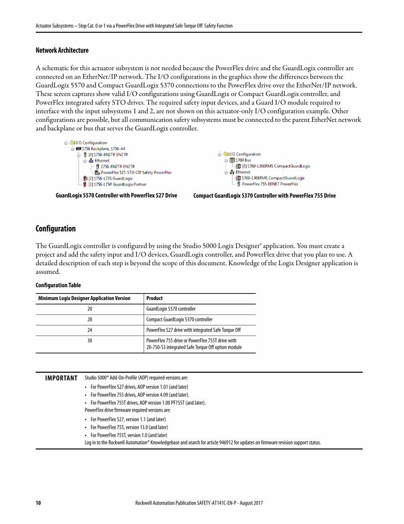
Network Architecture
A schematic for this actuator subsystem is not needed because the PowerFlex drive and the GuardLogix controller are connected on an EtherNet/IP network. The I/O configurations in the graphics show the differences between the GuardLogix 5570 and Compact GuardLogix 5370 connections to the PowerFlex drive over the EtherNet/IP network. These screen captures show valid I/O configurations using GuardLogix or Compact GuardLogix controller, and PowerFlex integrated safety STO drives. The required safety input devices, and a Guard I/O module required to interface with the input subsystems 1 and 2, are not shown on this actuator-only I/O configuration example. Other configurations are possible, but all communication safety subsystems must be connected to the parent EtherNet network and backplane or bus that serves the GuardLogix controller.
Configuration
The GuardLogix controller is configured by using the Studio 5000 Logix Designer® application. You must create a project and add the safety input and I/O devices, GuardLogix controller, and PowerFlex drive that you plan to use. A detailed description of each step is beyond the scope of this document. Knowledge of the Logix Designer application is assumed.
Configuration Table
Minimum Logix Designer Application Version Product
20 GuardLogix 5570 controller
28 Compact GuardLogix 5370 controller
24 PowerFlex 527 drive with integrated Safe Torque Off
30 PowerFlex 755 drive or PowerFlex 755T drive with 20-750-S3 integrated Safe Torque Off option module
IMPORTANT Studio 5000® Add-On-Profile (AOP) required versions are:
• For PowerFlex 527 drives, AOP version 1.01 (and later)• For PowerFlex 755 drives, AOP version 4.09 (and later).• For PowerFlex 755T drives, AOP version 1.00 PF755T (and later). PowerFlex drive firmware required versions are:
• For PowerFlex 527, version 1.1 (and later)• For PowerFlex 755, version 13.0 (and later)• For PowerFlex 755T, version 1.0 (and later)Log in to the Rockwell Automation® Knowledgebase and search for article 946912 for updates on firmware revision support status.
GuardLogix 5570 Controller with PowerFlex 527 Drive Compact GuardLogix 5370 Controller with PowerFlex 755 Drive
10 Rockwell Automation Publication SAFETY-AT141C-EN-P - August 2017

Actuator Subsystems – Stop Cat. 0 or 1 via a PowerFlex Drive with Integrated Safe Torque Off Safety Function
Configure the GuardLogix Controller and PowerFlex Drive
Integrated Safety requires that certain controller, communication, and drive properties are configured to use the CIP safety connections. The following steps are the minimum requirements for configuring your GuardLogix 5570 or Compact GuardLogix 5370 Logix Designer project to use the Integrated Safety Safe Torque Off (STO) features of the PowerFlex 527 drive and PowerFlex 755 or PowerFlex 755T drive with 20-750-S3 STO option module.
The following discussion does not cover all the steps required to properly configure the GuardLogix controller and PowerFlex drive applications. Refer to the following PowerFlex user manuals that provide detailed instructions about how to use the Logix Designer PowerFlex device Add-On-Profiles (AOP) for Ethernet communication adapters:
• PowerFlex 527 Adjustable Frequency AC Drive User Manual, publication 520-UM002• PowerFlex 755 Drive Embedded EtherNet/IP Adapter User Manual, publication 750COM-UM001• PowerFlex 750-Series Drives with TotalFORCE™ Control Built-in EtherNet/IP Adapter User Manual,
publication 750COM-UM009• PowerFlex 20-750-ENETR Dual-port EtherNet/IP Option Module User Manual,
publication 750COM-UM008
Note: Screen captures are shown to clarify certain settings and may not reflect the appearance of screen displays you see while configuring the various devices used in this safety function.
1. Open your existing Logix Designer GuardLogix project, or create a new project with a GuardLogix controller.Valid Compact GuardLogix and GuardLogix controllers and associated firmware revision requirements are shown in the Configuration Table on page 10.
2. To enable Time Synchronization for the controller, do the following:a. Open the Controller Properties dialog box and select the Date/Time tab.b. Select 'Enable Time Synchronization' for the controller.
This is how the dialog box appears for the GuardLogix 5570 controller. The dialog box for other GuardLogix controllers has a similar appearance.
Rockwell Automation Publication SAFETY-AT141C-EN-P - August 2017 11

Actuator Subsystems – Stop Cat. 0 or 1 via a PowerFlex Drive with Integrated Safe Torque Off Safety Function
3. For this safety function example, a 1756-EN2TR 2-port EtherNet Bridge module is being added to the GuardLogix 5570 controller Logix project. If you are using a Compact GuardLogix 5370 controller, skip to step 7. Otherwise, to add the 1756-EN2TR module, do the following:a. Create the 1756-EN2TR 2-port Ethernet Bridge module by adding it to the ControlLogix backplane where
the GuardLogix controller is located.b. Name the module.c. Type an IP address for the module.
This example uses 192.168.1.2 as the IP address. Your IP address can differ.d. Click Change.
4. In the Module Definition dialog box, choose ‘Time Sync and Motion’ from the Time Sync Connection pull-down menu.
5. To accept the setting and return to the New Module dialog box, click OK.6. To finish creating the 1756-EN2TR module, click OK in the New Module dialog box.
12 Rockwell Automation Publication SAFETY-AT141C-EN-P - August 2017

Actuator Subsystems – Stop Cat. 0 or 1 via a PowerFlex Drive with Integrated Safe Torque Off Safety Function
7. If you are using a GuardLogix 5570 controller, skip this step. Otherwise, complete the following steps:Note: You must be Online with the Compact GuardLogix controller to set the IP address.a. Open the Controller Properties dialog box and select the Internet Protocol tab.b. Select the 'Manually configure IP settings' radio button.c. Enter the IP Address and Subnet Mask.
The Compact GuardLogix controller is automatically configured for the Time Synchronization connection.
8. To add the PowerFlex drive to the EtherNet network, right-click the Ethernet network under the 1756-EN2TR parent module, and choose New Module.
GuardLogix 5570 Controller Organizer Compact GuardLogix 5370 Controller Organizer
Rockwell Automation Publication SAFETY-AT141C-EN-P - August 2017 13

Actuator Subsystems – Stop Cat. 0 or 1 via a PowerFlex Drive with Integrated Safe Torque Off Safety Function
9. In the New Module dialog box opens, do the following:a. Type a name for your PowerFlex drive. b. Set a unique IP address for your PowerFlex drive.
In these screen captures, 'PowerFlex' was used as the Name, and 192.168.1.10 was used as the IP address. Your IP address can differ.
c. Verify that the Parent network for the new PowerFlex drive is assigned to the Ethernet module or Local (embedded) Ethernet network that is associated with the GuardLogix controller.
10. If you are using a PowerFlex 527 drive, skip to step 12. If you are using a PowerFlex 755T drive, skip to step 11. If you are using a PowerFlex 755 drive, complete the following steps to set the firmware revision, and then continue with step 11.a. Click Change.b. In the Module Definition dialog box, use the Revision pull-down menu and select revision 13 or later.c. To accept the change and close the Module Definition dialog box, click OK.
IMPORTANT For the PowerFlex 755 drive, firmware revision 13 or later is required for Integrated Safety. For the PowerFlex 755T drive, all current revision levels of firmware are compatible with Integrated Safety. If required, you can set a compatible firmware revision level to match your PowerFlex drive revision.
GuardLogix 5570 with PowerFlex 527 Compact GuardLogix 5370 with PowerFlex 755
14 Rockwell Automation Publication SAFETY-AT141C-EN-P - August 2017

Actuator Subsystems – Stop Cat. 0 or 1 via a PowerFlex Drive with Integrated Safe Torque Off Safety Function
11. To add the 20-750-S3 STO Integrated Safety peripheral device to the PowerFlex 755 or PowerFlex 755T drive control backplane, do the following:a. Open the PowerFlex 755 or PowerFlex 755T Module Properties dialog box and add the 20-750-S3 Network
STO peripheral device.b. Choose a port to install the 20-750-S3 STO option module.
Valid ports for the 20-750-S3 module are 4, 5, or 6.c. Verify that Electronic Keying is set to 'Compatible Module'.
12. The PowerFlex drive must include a '…Safety' connection to make sure that safety is being managed by the GuardLogix controller. To create this connection, do the following:a. For the PowerFlex 755 and PowerFlex 755T drive, select 'Safety only' or 'Standard and Safety'.
For this safety function example we are using the GuardLogix controller for both safety and drive control, so we need to select 'Standard and Safety' for the PowerFlex 755 and PowerFlex 755T.
This screen shot is for the Module Definition dialog box for the PowerFlex 755 drive. The dialog boxes for the PowerFlex 755T drive have a different appearance.
b. For the PowerFlex 527 drive, select 'Safety only' or 'Motion and Safety.’For this safety function example we are using the GuardLogix controller for both safety and drive control, so we need to select 'Motion and Safety' for the PowerFlex 527 drive.All current firmware revision levels of the PowerFlex 527 drive are compatible with Integrated Safety. If required, you can set the firmware revision level to match your PowerFlex drive revision.
TIP While the PowerFlex drive Module Definition dialog box is open, you can modify the drive rating, power structure, and other pertinent information to match your PowerFlex drive hardware configuration.
Rockwell Automation Publication SAFETY-AT141C-EN-P - August 2017 15

Actuator Subsystems – Stop Cat. 0 or 1 via a PowerFlex Drive with Integrated Safe Torque Off Safety Function
13. When all drive and safety module properties are configured correctly, the Module Properties General tab should show the safety connection and Safety Network Number.
This screen capture is for a PowerFlex 755 drive. The dialog boxes for the PowerFlex 527 and PowerFlex 755T drives have a different appearance.
Programming
The accumulated 'Safety_Interlocks_OK' tag is the resultant output from the safety input and logic subsystems. It is used as a permissive in the Safe Torque Off logic. Rung 2 in the safety program logic screen captures show this tag. If the 'Safety_Interlocks_OK' tag goes false (0), it initiates the Safe Torque Off function. The Safe Torque Off function remains false (0) until a manual reset action is implemented after the 'Safety_Interlocks_OK' tag goes true (1).
The PowerFlex integrated safety Safe Torque Off function requires a reset after the STO function is initially energized. Rung 1 in the safety program logic accomplishes this reset. For details on the reset function, see the STO Reset topic in the appropriate PowerFlex drive manual, which is listed in the Additional Resources on page 24.
The STO output is energized if the safety interlocks are satisfied, there are no faults, there is a valid connection, and there is a falling edge on the reset button.
Safety Program Logic – Stop Category 0
The following code is an example for a stop category 0. When a demand is placed on safety interlocks, and the accumulated 'Safety_Interlocks_OK' tag goes to false (0), then the 'PowerFlex:SO.SafeTorqueOff ' output immediately goes to false (0) as well.
16 Rockwell Automation Publication SAFETY-AT141C-EN-P - August 2017

Actuator Subsystems – Stop Cat. 0 or 1 via a PowerFlex Drive with Integrated Safe Torque Off Safety Function
if
Safety Program Logic – Stop Category 1
The following code is an example for a stop category 1. When a demand is placed on safety interlocks, and the accumulated 'Safety_Interlocks_OK' tag goes to false (0), the 'STO_enable' tag goes false (0) immediately. This action energizes the 'Drive_Stop' tag. The 'PowerFlex:SO.SafetTorqueOff ' output goes to false (0) after the 'CAT1-delay' timer times out. The length of the delay is determined in the risk assessment. In this example the delay time is three seconds.
The 'Drive_Stop' tag is used to initiate a controlled stop of the drive, for example;• The PowerFlex 755 drive in standard I/O parameter mode 'Drive_Stop' could control the
'PowerFlex:O.LogicCommand_Stop' tag in a standard controller Task.• The PowerFlex 527 drive 'Drive_Stop' could control a Motion Axis Stop (MAS) instruction.
Rockwell Automation Publication SAFETY-AT141C-EN-P - August 2017 17

Actuator Subsystems – Stop Cat. 0 or 1 via a PowerFlex Drive with Integrated Safe Torque Off Safety Function
Falling Edge Reset
ISO 13849-1 stipulates that instruction reset functions must occur on falling edge signals. To comply with this requirement, a One Shot Falling (OSF) instruction is used on the reset rung. Then, the OSF instruction Output Bit tag is used as the reset bit for the STO output rung.
Calculation of the Performance Level
When properly implemented, the PowerFlex 527 subsystem can be used in a safety function that achieves a safety rating of category 3, Performance Level e (cat. 3, PLe), according to ISO 13849-1: 2008, as calculated by using the SISTEMA software PL calculation tool.
When properly implemented, the PowerFlex 755 or the PowerFlex 755T drive with the 20-750-S3 module subsystem can be used in a safety function that achieves a safety rating of category 3, Performance Level e (cat. 3, PLe), according to ISO 13849-1: 2015, as calculated by using the SISTEMA software PL calculation tool.
IMPORTANT To calculate the PL of your entire safety function, you must include the sensor subsystems along with the logic and actuator subsystems shown here. Depending on the sensor subsystems and devices you choose, the overall safety rating of your system could be reduced. An example that describes how to calculate the safety rating for a complete safety function appears in the section titled Complete Safety Function PL Calculation Example on page 20.
18 Rockwell Automation Publication SAFETY-AT141C-EN-P - August 2017

Actuator Subsystems – Stop Cat. 0 or 1 via a PowerFlex Drive with Integrated Safe Torque Off Safety Function
Logic and Actuator Subsystem Calculation
The table shows the percentage of Ple bandwidth that each subsystem uses, and the proof test interval (PTI) of that subsystem.
The category and Performance Level of each subsystem are shown in the graphics.
Controller/Subsystem Function % of PLe Bandwidth Used PTI (years)
GuardLogix 5570 controllerLogic
1.2%
20
Compact GuardLogix 5370 controller 1.5%
PowerFlex 755 Frame 1…7, 20-750-S3 STO subsystem
Actuator
1.79%
PowerFlex 755 Frame 8, 20-750-S3 STO subsystem 3.41%
PowerFlex 755 Frame 9, 20-750-S3 STO subsystem 4.46%
PowerFlex 755 Frame 10, 20-750-S3 STO subsystem 5.51%
PowerFlex 755T Frame 8, 20-750-S3 STO subsystem 4.28%
PowerFlex 755T Frame 9, 20-750-S3 STO subsystem 4.57%
PowerFlex 755T Frame 10, 20-750-S3 STO subsystem 4.87%
PowerFlex 755T Frame 11, 20-750-S3 STO subsystem 5.17%
PowerFlex 755T Frame 12, 20-750-S3 STO subsystem 5.47%
PowerFlex 527 integrated STO subsystem 1.70%
Rockwell Automation Publication SAFETY-AT141C-EN-P - August 2017 19

Actuator Subsystems – Stop Cat. 0 or 1 via a PowerFlex Drive with Integrated Safe Torque Off Safety Function
Model the logic and actuator subsystems as follows.
Complete Safety Function PL Calculation Example
This example takes one of the logic subsystems and the PowerFlex 527 actuator subsystem from this document and combines them with the sensor subsystems from Door-monitoring Interlock Switch with an Integrated Safety Controller Safety Function Application Technique, publication SAFETY-AT034, to illustrate how any sensor subsystems can be added to the output subsystems within this publication. If you choose different products, you need new calculations.
Assuming the use of the following subsystem choices, the overall Performance Level that is achieved is shown in the graphic:
Here are the subsystems from Door-monitoring Interlock Switch with an Integrated Safety Controller Safety Function Application Technique, publication SAFETY-AT034 – sensor, logic, and actuator:
Subsystem 1 Subsystem 2 Subsystem 3
Sensor/Input ActuatorLogic
GuardLogix Controller
Determined by the safety function
sensor subsystem you choose
PowerFlex Drive with Integrated Safe Torque Off
20 Rockwell Automation Publication SAFETY-AT141C-EN-P - August 2017

Actuator Subsystems – Stop Cat. 0 or 1 via a PowerFlex Drive with Integrated Safe Torque Off Safety Function
The sensor subsystems from Door-monitoring Interlock Switch with an Integrated Safety Controller Safety Function Application Technique, publication SAFETY-AT034, are the SensaGuard Interlock Switch and the 1734-IB8S POINT Guard I/O™ input module. The overall safety function is shown here. It combines those sensor subsystems from publication SAFETY-AT034, and the logic and actuator subsystems from this document.
The PFH values for each subsystem in the safety function that is modeled in the graphic are taken from their respective publications and combined.
Verification and Validation Plan
Verification and validation play important roles in the avoidance of faults throughout the safety system design and development process. ISO 13849-2 sets the requirements for verification and validation. The standard calls for a documented plan to confirm that all safety functional requirements have been met.
Verification is an analysis of the resulting safety control system. The Performance Level (PL) of the safety control system is calculated to confirm that the system meets the required Performance Level (PLr) specified. The SISTEMA software is typically used to perform the calculations and assist with satisfying the requirements of ISO 13849-1.
IMPORTANT The PFH for this complete safety function, with the sensor, logic, and actuator subsystems, is 4.53E-09, which consumes 4.53% of the PLe bandwidth. The PL for the complete safety function is PLe.
Subsystem 1 Subsystem 2 Subsystem 3 Subsystem 4
Sensor Input Logic Actuator
1734-IB8SSensaGuard
Switch
GuardLogix Controller 1756-L73S
PowerFlex 527 Drive with Integrated Safe
Torque Off
Rockwell Automation Publication SAFETY-AT141C-EN-P - August 2017 21

Actuator Subsystems – Stop Cat. 0 or 1 via a PowerFlex Drive with Integrated Safe Torque Off Safety Function
Validation is a functional test of the safety control system to demonstrate that the system meets the specified requirements of the safety function. The safety control system is tested to confirm that all safety-related outputs respond appropriately to their corresponding safety-related inputs. The functional test includes normal operating conditions and potential fault injection of failure modes. A checklist is typically used to document the validation of the safety control system.
Before you validate the GuardLogix Safety System, confirm that the safety system and safety application program have been designed in accordance with the GuardLogix 5570 and Compact GuardLogix 5370 Controller Systems Safety Reference Manual, publication 1756- RM099, and the GuardLogix Safety Application Instruction Set Safety Reference Manual, publication 1756-RM095.
The following plan assumes a stop category 0 stop is being used. You must make appropriate adaptations to the plan if your safety function requires a stop category 1.
Verification and Validation Checklist
General Machinery Information
Machine Name/Model Number
Machine Serial Number
Customer Name
Test Date
Tester Name
Schematic Drawing Number
Controller Name
Safety Signature ID
Safety Network Number
Logix Designer Application
Safety Control System Modules GuardLogix Modules Firmware Revision
GuardLogix Safety Controller 1756-L73S V24 and later
Logix Ethernet Bridge 1756-EN2TR
PowerFlex Drive PowerFlex 527
Sensor subsystem SensaGuard Switch
POINT Guard I/O Input Module 1734-IB8S
GuardLogix Safety System Configuration and Wiring Verification
Test Step Verification Pass/Fail Changes/Modifications
1Verify that the safety system has been designed in accordance with the GuardLogix 5570 and Compact GuardLogix 5370 Controller Systems Safety Reference Manual, publication 1756-RM099.
2Verify that the safety application program has been designed in accordance with the GuardLogix Safety Application Instruction Reference Manual, publication1756-RM095.
3 Visually inspect the safety system network and verify that the I/O is wired as documented in the schematics.
4 Visually inspect the Logix Designer application program to verify that the safety system network and I/O module configuration is configured as documented.
5Visually inspect the Logix Designer application program to verify that suitable safety- certified instructions are used. The logic must be readable, understandable, and testable with the aid of clear comments.
22 Rockwell Automation Publication SAFETY-AT141C-EN-P - August 2017

Actuator Subsystems – Stop Cat. 0 or 1 via a PowerFlex Drive with Integrated Safe Torque Off Safety Function
6 Verify that all input devices are qualified by cycling their respective actuators. Monitor the status in the Controller Tags window of the safety application.
7 Verify that all output devices are qualified by cycling their respective actuators. Monitor the status in the Controller Tags window of the safety application.
Normal Operation Verification - The GuardLogix safety system responds properly to all normal Start, Stop, and Reset commands.
Test Step Verification Pass/Fail Changes/Modifications
1Initiate a Start command. The Safe Torque Off (STO) feature of the PowerFlex drive must energize for a normal machine run condition. Verify proper machine status indication and safety application program indication.
2Initiate a Stop command. The STO feature of the PowerFlex drive must de-energize for a normal machine stop condition. Verify proper machine status indication and safety application program indication.
3
While the system continues to run, place a demand on the sensor subsystem. The STO feature of the PowerFlex drive must de-energize for a normal safe condition. Verify proper machine status indication and safety application program indication. Repeat for all sensor subsystems.
4
While the system is stopped with the sensor subsystems in a safe state, initiate a Start command. The STO feature of the PowerFlex drive must remain de-energized for a normal safe condition. Verify proper machine status indication and safety application program indication.
5While the system is stopped with the sensor subsystems in a safe state, initiate a Reset command. The STO feature of the PowerFlex drive must remain de-energized. Verify proper machine status indication and safety application program indication.
Validation of Safe Response to Abnormal Operation - The safety system responds properly to all foreseeable faults with corresponding diagnostics.
GuardLogix Controller and Network Tests
Test Step Validation Pass/Fail Changes/Modifications
1
To find a safety function application technique that uses the type of input device you plan to use, refer to:http://marketing.rockwellautomation.com/safety/en/safety_functionsUse the input section of that validation procedure as a guide to test your input device.
2
While the system continues to run, remove the EtherNet/IP network connection between the PowerFlex drive and the controller. The STO feature of the PowerFlex drive must de-energize. Verify proper machine status indication and I /O connection status in the safety application program.
3 Restore the EtherNet/IP connection and allow time to re-establish communication. Verify that the STO feature of the PowerFlex drive does not automatically energize.
4
While the system continues to run, switch the controller out of Run mode. The PowerFlex drive must de-energize. Return the controller to Run mode. The STO feature of the PowerFlex drive must remain de-energized. Verify proper machine status indication and safety application program indication.
Validation of Safe Response to Abnormal Operation - The safety system responds properly to all foreseeable faults with corresponding diagnostics.
Safety Output Test
Test Step Validation Pass/Fail Changes/Modifications
1Initiate a Safety Reset command. The STO feature of the PowerFlex drive must energize for a normal machine run condition. Verify proper machine status indication and safety application program indication.
IMPORTANT In addition to using the verification and validation steps that are provided here, consult the application technique for your input subsystem for the steps that are required to validate the input device. For the input subsystem example used in this safety function application technique, we reference Door-monitoring Interlock Switch with an Integrated Safety Controller Safety Function Application Technique, publication SAFETY-AT034.
Verification and Validation Checklist (continued)
Rockwell Automation Publication SAFETY-AT141C-EN-P - August 2017 23

Actuator Subsystems – Stop Cat. 0 or 1 via a PowerFlex Drive with Integrated Safe Torque Off Safety Function
Additional Resources
These documents contain more information about related products from Rockwell Automation.
You can view or download publications at http://www.rockwellautomation.com/global/literature-library/overview.page. To order paper copies of technical documentation, contact your local Allen-Bradley distributor or Rockwell Automation sales representative.
Resource Description
GuardLogix 5570 and Compact GuardLogix 5370 Controller Systems Safety Reference Manual, publication 1756-RM099
Describes the GuardLogix 5570 controller system. Provides instructions on how to develop, operate, or maintain a GuardLogix 5570 controller-based safety system that uses the Studio 5000 Logix Designer® application.
GuardLogix 5570 Controllers User Manual, publication 1756-UM022 Provides information on how to install, configure, and program the GuardLogix 5570 controllers in the Logix Designer application.
Compact GuardLogix 5370 Controllers User Manual, publication 1769-UM022 Provides information on how to install, configure, and program the Compact GuardLogix 5370 controllers in the Logix Designer application.
GuardLogix Safety Application Instruction Set Safety Reference Manual, publication 1756-RM095
Describes the Rockwell Automation® GuardLogix Safety Application Instruction Set. Provides instructions on how to design, program, or troubleshoot safety applications that use GuardLogix controllers.
PowerFlex 527 Adjustable Frequency AC Drive User Manual, publication 520-UM002 Provides information on how to install and configure the PowerFlex 527 AC drive.
PowerFlex 750-Series AC Drives Programming Manual, publication 750-PM001 Provides information on how to configure the PowerFlex 750 series AC drives.
PowerFlex 750 Series AC Drives Installation Instructions, publication 750-IN001 Provides information on how to install the PowerFlex 750 series AC drives.
PowerFlex Drives with TotalFORCE Control Programming Manual, publication 750-PM100 Provides information on how to configure the PowerFlex 755T series AC drives.
PowerFlex 750-Series Products with TotalFORCE Control Installation Instructions, publication 750-IN100 Provides information on how to install the PowerFlex 755T series AC drives.
PowerFlex 755 Integrated Safety - Safe Torque Off Option Module User Manual, publication 750-UM004
Provides information on how to install and configure the 20-750-S3 integrated STO option module.
PowerFlex 755 Drive Embedded EtherNet/IP Adapter User Manual, publication 750COM-UM001
Provides information on how to configure the PowerFlex 755 embedded EtherNet Adapter.
PowerFlex 750-Series Drives with TotalFORCE Control Built-in EtherNet/IP Adapter User Manual, publication 750COM-UM009
Provides information on how to configure the PowerFlex 755T embedded EtherNet Adapter.
PowerFlex 20-750-ENETR Dual-port EtherNet/IP Option Module User Manual, publication 750COM-UM008
Provides information on how to configure the PowerFlex 750-series EtherNet option module.
Door-monitoring Interlock Switch with an Integrated Safety Controller Safety Function Application Technique, publication SAFETY-AT034
Provides instructions on how to wire, configure, and program a Compact GuardLogix® controller and POINT Guard I/O™ module to monitor a safety gate by using a SensaGuard™ safety switch.
Industrial Automation Wiring and Grounding Guidelines, publication 1770-4.1 Provides general guidelines on how to install a Rockwell Automation industrial system.
Product Certifications website, http://www.rockwellautomation.com/global/certification/overview.page Provides declarations of conformity, certificates, and other certification details.
24 Rockwell Automation Publication SAFETY-AT141C-EN-P - August 2017

Actuator Subsystems – Stop Cat. 0 or 1 via a PowerFlex Drive with Integrated Safe Torque Off Safety Function
Notes:
Rockwell Automation Publication SAFETY-AT141C-EN-P - August 2017 25

Allen-Bradley, GUARD I/O, GuardLogix, LISTEN. THINK. SOLVE., POINT Guard I/ O, POINT I/O, PowerFlex, Rockwell Automation, Rockwell Software, SensaGuard, Studio 5000, Studio 5000 Logix Designer, and TotalFORCE are trademarks of Rockwell Automation, Inc.CIP Safety and EtherNet/IP are trademarks of ODVA, Inc.Trademarks not belonging to Rockwell Automation are property of their respective companies.
Publication SAFETY-AT141C-EN-P - August 2017
Rockwell Automation SupportUse the following resources to access support information.
Documentation FeedbackYour comments will help us serve your documentation needs better. If you have any suggestions on how to improve this document, complete the How Are We Doing? form at http://literature.rockwellautomation.com/idc/groups/literature/documents/du/ra-du002_-en-e.pdf.
Technical Support Center Knowledgebase Articles, How-to Videos, FAQs, Chat, User Forums, and Product Notification Updates. www.rockwellautomation.com/knowledgebase
Local Technical Support Phone Numbers Locate the phone number for your country. www.rockwellautomation.com/global/support/get-support-now.page
Direct Dial CodesFind the Direct Dial Code for your product. Use the code to route your call directly to a technical support engineer.
www.rockwellautomation.com/global/support/direct-dial.page
Literature Library Installation Instructions, Manuals, Brochures, and Technical Data. www.rockwellautomation.com/literature
Product Compatibility and Download Center (PCDC)
Get help determining how products interact, check features and capabilities, and find associated firmware.
www.rockwellautomation.com/global/support/pcdc.page
Rockwell Otomasyon Ticaret A.Ş., Kar Plaza İş Merkezi E Blok Kat:6 34752 İçerenköy, İstanbul, Tel: +90 (216) 5698400
Rockwell Automation maintains current product environmental information on its website at http://www.rockwellautomation.com/rockwellautomation/about-us/sustainability-ethics/product-environmental-compliance.page.
For more information onSafety Function Capabilities, visit:http://marketing.rockwellautomation.com/safety/en/safety_functions
Supersedes Publication SAFETY-AT141B-EN-P - October 2016 Copyright © 2017 Rockwell Automation, Inc. All rights reserved. Printed in the U.S.A.