ad 015 - defense technical information center · ing compound loctite ... these threaded fasteners...
TRANSCRIPT
UNCLASSIFIED
AD 262 015
4 Me
ARMED SERVICES TECHNICAL INFORMATION AGENCYARLINGTON HALL STATIONARLINGTON 12, VIRGINIA
UNCLASSIFIED
NOTICE: When government or other drawings, speci-fications or other data are used for any purposeother zhan in connection with a definitely relatedgovernment procurement operation, the U. S.Government thereby incurs no responsibility, nor anyobligation whatsoever; and the fact that the Govern-ment may have formulated, furnished, or in any waysupplied the said drawings, specifications, or otherdata is not to be regarded by implication or other-wise as in any manner licensing the holder or anyother person or corporation, or conveying any rightsor permission to manufacture, use or sell anypatented invention that may in any way be relatedthereto.

C) T MEMORANDUM REPORT
E M61-29-1SC
A HN THREADED FASTENERS LOCKING DEVICES
I EVALUATION OF LOCTITE SEALANTc
by
A S. M. Kalan
SE OMS 4230.1.1033.00.05p
0RT [T ....
May 1961
FRANKFORD ARSENALN
3 , P
tz: PHILADELPHIA 37, PA

Frankford Arsenal Memorandum Report M61-29-1Philadelphia 37, Pa. May 1961OMS 4230.1.1033.00.05
THREADED FASTENERS LOCKING DEVICESEVALUATION OF LOCTITE SEALANT
Prepared by:
ChiefMaterials Engineering Section
Reviewed by:R. D. FRANCEChiefBasic Materials Evaluation Branch
Approved by:J. J. CUMMINGSChiefEngineering Support Division

OBJECT
To evaluate the efficiency of LOCTITE Sealant as a fasteningmethod for the prevention of loosening of threaded fasteners due toshock and vibration. As a result of this investigation, it is desiredto obtain data necessary for the preparation of a specification forthis material if found to have the desired properties.
SUMMARY
LOCTITE Sealart Compound was investigated for its ability asa screw locking material to prevent threaded fasteners from looseningunder shock and vibration environments. Three grades of LOCTITE,having shear strengths of 75(H), 300(E), and 750(C)psi, were evaluated.Under the worst condition - alternate shock (1500 G) and elliptic vibra-tion (4 G at 5 to 45 cps) - the weakest grade was as effective in pre-venting "walkout" as nylon insert screws, and "dab" materials, MIL-V-173 varnish and MIL-S-11031 sealing compound. A subsequentmathematical analysis showed that the test vibration conditions werevery mild with effective developed torques of considerably less than0.5 inch pound. It is recommended that the investigation be continuedto verify this analysis which indicates that the design of a quantitativetest is feasible and desirable.
LOCTITE Sealant compounds should not be relied upon for fasten-ing under high frequency, high amplitude vibrationconditions. LOCTITEGrades A., C, and H are adequately covered by Military SpecificationMIL-S-40083(ORD) although a vibration performance test requirementwould be desirable. Application after fastener insertion is undesirablesince extent of penetrability is unpredictable.
AUTHORIZATION
OMS 4230.1.1033.00.05
Forms 1183A dated 25 June 1959 and 3 October 1960
W.D. 90304231-07-55001-01
X.O. 97235-01; 05964-03
ii

TABLE OF CONTENTS
Section Title Page No.
OBJECT .. .. ..... .. .. .. .. .. .. . ..i
SUMMARY ....................................... ii
AUTHORIZATION ............ ......................... ii
INTRODUCTION ........ ........................... 1
DESCRIPTION OF MATERIAL ......... .................. 1
TEST PROCEDURES AND RESULTS ........ ............... 3
DISCUSSION ............. ........................... 20
CONCLUSIONS .......................... 30
RECOMMENDATIONS ....... ..................... ..... 32
BIB LIOGRAPHY ......... ........................ .... 33
DISTRIBUTION .......... ....................... ..... 34
LIST OF ILLUSTRATIONS
Figure Title
1 View of Screw Assembly, Screw Assembly Dis-assembled, Plate with Six Screw Assemblies andApplicator Top Bottle of LOCTITE "H"1 .............. 2
2 Original Test Setup on Vibration Machine ...... 12
3 Threaded Fastener Locking Devices - SimultaneousShock*& Vibration Test Fixture .. .......... .... 13
4 Threaded Fastener Locking Devices - AlternateShock and Vibration Test Setup .............. . 16
iii
LIST OF ILLUSTRATIONS (Cont'd)
Figure Title Page No.
5 Threaded Fastener Locking Devices - AlternateShock and Vibration Test with Pendulum ImpactDevice in Place ....... .................... .. 17
6 Threaded Fastener Locking Devices - Screw Lock-ing Compound LOCTITE - Original Characteristics . 19
7 Threaded Fastener Locking Devices - Screw Lock-ing Compound LOCTITE - Effect of Shock andVibration .......... ........................ ... 21
8 Threaded Fastener Locking Devices - Screw Lock-ing Compound LOCTITE - Effect of Shock andVibration ........... ....................... 22
9 Threaded Fastener Locking Devices - Screw Lock-ing Compound LOCTITE - Effect of Shock andVibration ......... ......................... .... 23
10 Threaded Fastener Locking Devices - Screw As-sernbly Relative to Vibration Orbit ............ ... 25
11 Threaded Fastener Locki.ng Devices - Diagram ofVibrating Screw Relative to Vibration Axis ......... ... 26
12 Threaded Fastener Locking Devices - Developed
"Walk-out" Torque as a Function of the VibrationDisplacement Angle Position of Screw ...... .... 29
iv

INTRODUCTION
In the ope,'atlon of military equipment, malfunctioning has beenased by loosening of threaded fasteners under vibration and shock
environment. These threaded fasteners may be of the headed type forjoining parts or the headless type for adjustment purposes.
Mechanical methods such as lock washers, cotter pins, staking,etc. do not completely prevent "walkout", complicate the design un-necessarily or are impossible to use.
Frankford Arsenal conducted several investigations 3* todevelop a universal locking system with a locking compound whichcould be applied by "dab' or other similar means to the screw-platejunction of the assembly. The objective was to prevent motion of thescrew during shock and vibration and yet allow disassembly to beeasily accomplished without damage to it. Under the test conditionsused, only Paraphenyl phenol Formaldehyde Varnish, MIL-V-173 andSealing Compound, MIL-S-11031 materials met the requirements.Nylon insert fasteners were also found to perform as well as thesematerials.
However, the use of these "dab" type materials imposed severalundesirable processing techniques and the search for materials withwider application tolerance has been continuous.
In recent years LOCTITE Sealant has been proposed as a ma-terial which may have the desirable characteristics without the compli-cations.
This investigation was undertaken to evaluate the claims made bythe manufacturer and the ability of LOCTITE to meet the antivibrationshock loosening requirements for military materiel.
DESCRIPTION OF MATERIAL4 ' 5
LOCTITE Sealants arE: modified polyester materials in fluid formsupplied in various viscositts and colors in polyethylene squeeze dis-pensing bottles (fig. 1) and are designed for a number of developedshear strengths after curing. (See Table I.)
*See Bibliography references.
4
AH4,
U -o
)Cu
ICI
El)<
uqu
mn
U0-4l77 >, 0 .
C)
- u u X=
00 xtoQ
. '-
S "'. 0
ox "
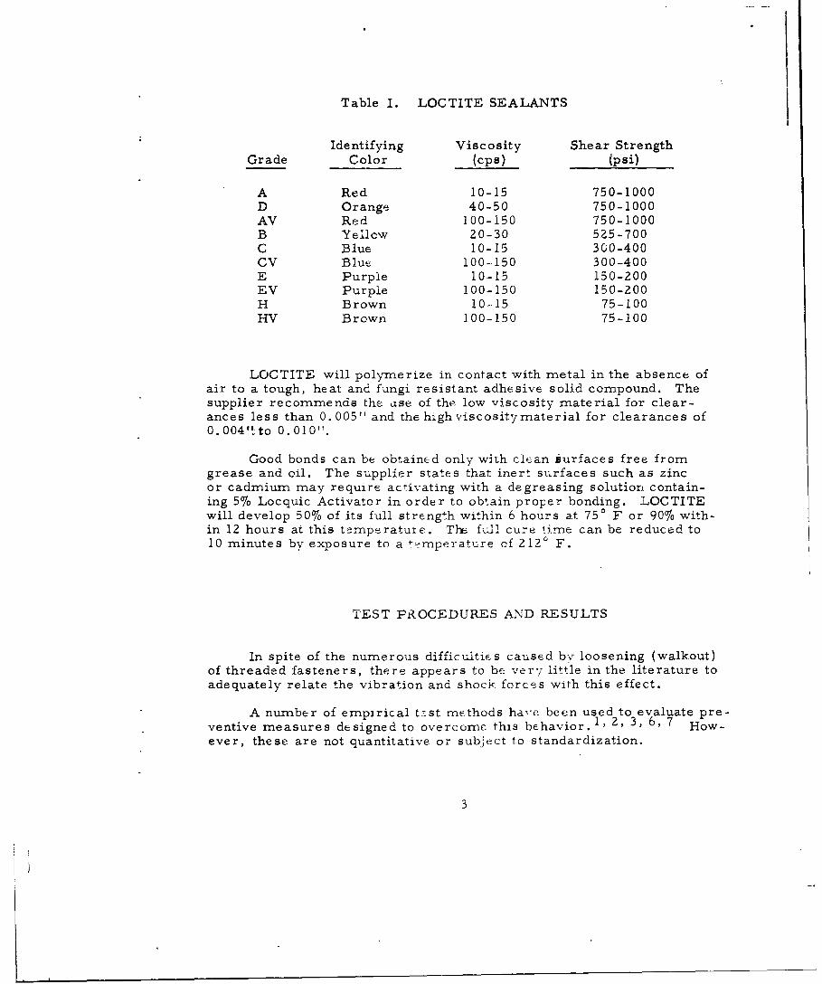
Table I. LOCTITE SEALANTS
Identifying Viscosity Shear StrengthGrade Color (cps) (psi)
A Red 10-15 750-1000D Orange 40-50 750-1000AV Red 100-150 750-1000B Yellow 20-30 525-700C Blue 10-15 300-400CV Blue 100-150 300-400E Purple 10-15 150-200EV Purple 100-150 150-200H Brown 10-.15 75-100HV Brown 100-150 75-100
LOCTITE will polymerize in contact with metal in the absence ofair to a tough, heat and fungi resistant adhesive solid compound. Thesupplier recommends the use of the low viscosity material for clear-ances less than 0.005" and the high viscositymaterial for clearances of0.004'1to 0.010".
Good bonds can be obtained only with clean iurfaces free fromgrease and oil. The supplier states that inert surfaces such as zincor cadmium may require activating with a degreasing solution contain-ing 5% Locquic Activator in order to obtain proper bonding. LOCTITEwill develop 50% of its full strength within 6 hours at 750 F or 90% with-in 12 hours at this temperatute. The full cure time can be reduced to10 minutes by exposure to a temperatu-re of 212" F.
TEST PROCEDURES AND RESULTS
In spite of the numerous difficultics caused by loosening (walkout)of threaded fasteners, there appears to be ver7 little in the literature toadequately relate the vibration and shock forces with this effect.
A number of empirical test methods have been used to evaluate pre-ventive measures designed to overcome this behavior. 1, 2, 3, 6, 7 How-ever, these are not quantitative or subject to standardization.
3

In the work that was previously done at Frankford Arsenal, screwscould be made to {'whlkout" under vibration only with the introduction ofhigh shock impulses imposed during the test.
Three test procedures were evolved during the course of this in-vestigation in an attempt to yield a reproducible condition severe enoughto cause loosening. The only machine available for this investigationwas a LAB 200 vibrator. The machine is capable of simultaneous vibra-tion in two directions, vertical and horizontal, with a maximum doubleamplitude of 0. 2 5 "''over a frequency range of 5 to 60 cps.
The test specimens consisted of twelve 3" x 6" x 3/4" metal plates
(fig. 1) prepared as follows:
1. Metals
a. Two plates - 7075 aluminum alloy.
b. Two plates - 7075 aluminum alloy with black anodizetreatment MIL-STD- 171, Finish 7.2.2.
c. Two plates - 1020 steel.
d. Two plates - 1020 steel with cadmium plate treatment,MIL-STD-171, Finish 1. 1. 1.2.
e, Two plates - 85-5-5-5 copper alloy.
f. Two plates - 85-5-5-5 copper alloy with black oxidetreatment MIL-STD-172, Finish 3.2.
Note: All treatments were done after all machining was completed.
2. Machining
Six evenly spaced holes were drilled and tapped on the cir-cumference of a two-inch diameter circle in each plate. In order toavoid the effects of burrs and other '"hold up" variables of the tapedthreads, the machining procedures of the previous investigations wereused. These are described below.
Step 1 - Drill 11/64 inch hole completely through the plate
Step 2 - Tap with #10-32 American Standard machine tap
Step 3 - Ream with #15 drill
Step 4 - Clean in degreasing solution
4
3. Machine Screws
No. 10-32 class 2 American Standard fillister head machinescrews, 3/4 inch long (fig. 1) were used in all tests. Since the purposewas to evaluate the locking compound, tests were made with a 1/2 inchthread engagement length with no tightening torque.
4. Application of LOCTITE
A drop of LOCTITE was applied to each of 5 screws of eachplate at the screw-plate junction after insertion allowing the liquid topenetrate into the space between the screw threads and plate. TheLOCTITE was allowed to cure for at least three days at room tempera-ture before tests were made. The sixth screw was inserted without anyLOCTITE treatment and served as a control in all tests.
The following measurements and observations were made toevaluate the effectiveness of the locking compound.
a. Break-Loose Torque (TB)
Sturdevant torque wrenches were used to determine thetorque required to start rotation of the screw.
b. Prevailing Torque (TP)
Sturdevant torque wrenches were used to determine themaximum torque required to rotate the screw one-half turn immediatelyafter "break-loose".
c. ''Walkout"
Visual observations for rotation tendencies of the screwswere made during the vibration and shock testing. Time for complete"walkout" of the screws was measured from the start of the vibrationcycles.
The test specimens were subjected to vibration and shock asdescribed below. The test results abstracted from Frankford ArsenalMemorandum Report M61-20-1 entitled "A Preliminary Investigationof a Thread Locking Compound" are tabulated in Tables II to VII.
5

Table II. ORIGINAL CHARACTERISTICS
7075 Aluminum 85-5-5-5 Copper 1020 Steel
Torque Torque Torque(in. -lb) (in. -lb) (in. -lb)
Condition T B Tp Condition TB Tp Condition TB Tp
LOCTITE H
As fabri- 6 4 As fabri- 5 2 As fabri- 4 4cated 8 6 cated 6 4 cated 4 4
7 4 8 5 10 610 5 11 7 9 4.5
6 3 11 6 10.5 7.56 4 4 3 8 46 4 4 2 10 68 6 6 2 9 5
10 7 4 2 10 64 2 10 5 5 54 2 6 4 3 36 3 7 4 6 46 3 9 5 6 47 3 10 5 11 56 3 10 5 10 68 3 10 5 10 56 2 8 5 8 4
Average 6.7 -3.8 Average 7.59 4.18 Average 7.8 4.9
7 1.63 1.44 2.45 1.46 2.55 1.21
Black 12 5.5 Black 13 6 Cadmium 5 4Anodize 11 6 Oxide 11 7 Plate 5 3
Average 11.5 5.75 Average 12 6.5 Average 5 3.5
LOCTITE E
As fabri- 17 12 As fabri- 20 16 As fabri- 25 18cated 20 10 cated 12 10 cated 28 18
LOC TITE C
As fabri- 28 28 As fabri- 20 18 As fabri- 34 26cated 14 14 cated 32 20 cated 40 25
6
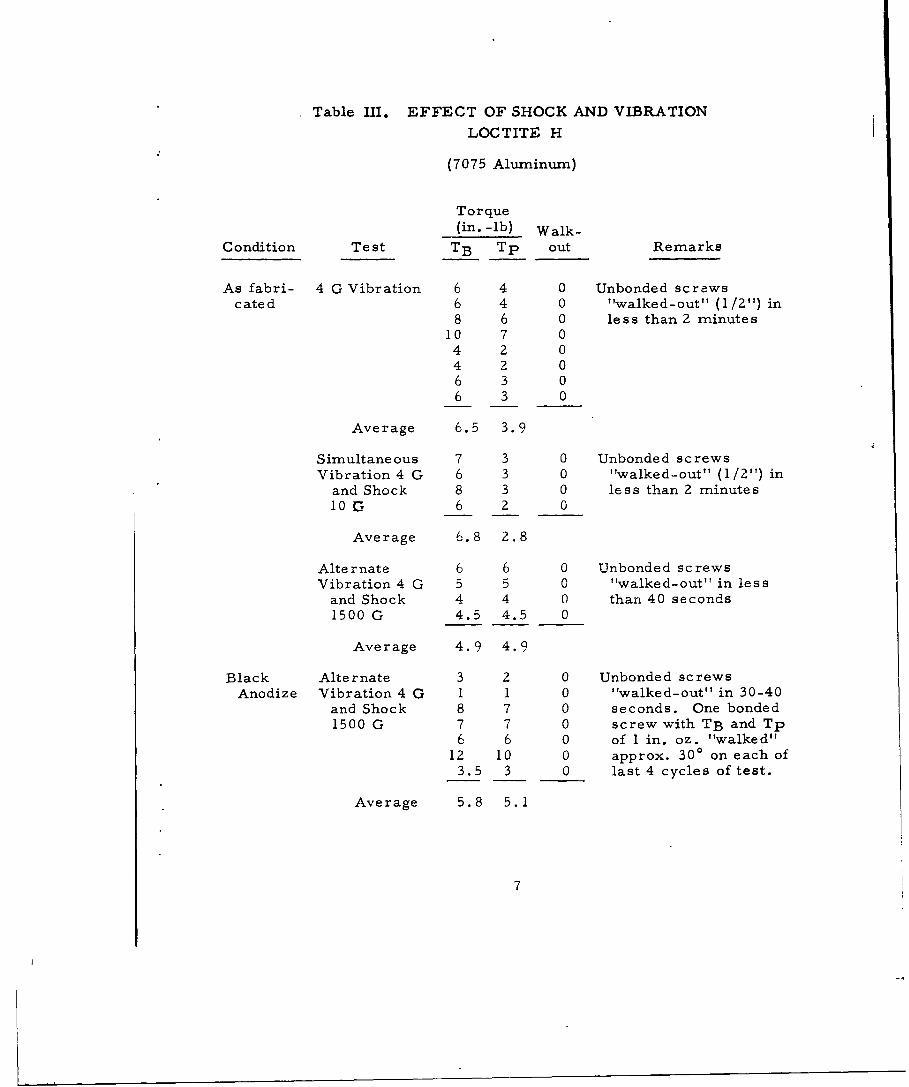
Table III. EFFECT OF SHOCK AND VIBRATION
LOCTITE H
(7075 Aluminum)
Torque(in. -lb) Walk-
Condition Test TB Tp out Remarks
As fabri- 4 G Vibration 6 4 0 Unbonded screwscated 6 4 0 "walked-out" (1/2") in
8 6 0 le s s than 2 minutes10 7 04 2 04 2 06 3 06 3 0
Average 6.5 3.9
Simultaneous 7 3 0 Unbonded screwsVibration 4 G 6 3 0 "walked-out" (1/2") in
and Shock 8 3 0 less than 2 minutes10G 6 2 0
Average 6.8 2.8
Alternate 6 6 0 Unbonded screwsVibration 4 G 5 5 0 "walked-out" in less
and Shock 4 4 0 than 40 seconds1500 G 4.5 4.5 0
Average 4.9 4.9
Black Alternate 3 2 0 Unbonded screwsAnodize Vibration 4 G 1 1 0 "walked-out" in 30-40
and Shock 8 7 0 seconds. One bonded1500 G 7 7 0 screw with TB and Tp
6 6 0 of 1 in. oz. "walked"12 10 0 approx. 300 on each of
3.5 3 0 last 4 cycles of test.
Average 5.8 5.1
7
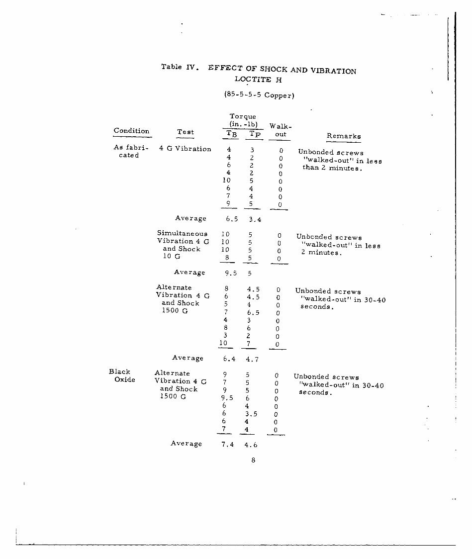
Table IV. EFFECT OF SHOCK AND VIBRATIONLOC TITE H
(85-5-5-5 Copper)
Torque(in. -lb) Walk-
Condition Test TB Tp out Remarks
As fabri- 4 G Vibration 4 3 0 Unbonded screwscated 4 2 0 "walked-out" in less6 2 0 than 2 minutes.4 2 0
10 5 06 4 07 4 09 5 0
Average 6.5 3.4
Simultaneous 10 5 0 Unbcnded screwsVibration 4 G 10 5 0 "walked-out" in lessand Shock 10 5 0 2 minutes.10G 8 5 0
Average 9.5 5Alternate 8 4.5 0 Unbonded screwsVibration 4 G 6 4.5 0 "walked-out" in 30-40and Shock 5 4 0 seconds.
1500 G 7 6.5 04 3 08 6 03 2 0
10 7 0
Average 6.4 4.7
Black Alternate 9 5 0 Unbonded screwsOxide Vibration 4 G 7 5 0 twalked-out" in 30-40and Shock 9 5 0 seconds.1500 G 9.5 6 0
6 4 06 3.5 06 4 07 4 0
Average 7.4 4.6
8

Table V. EFFECT OF SHOCK AND VIBRATIONLOCTITE H
(1020 Steel)
Torque(in. -1b) Walk-
Condition Te st TB Tp out Remarks
As fabri- 4 G Vibration 8 4 0 Unbonded screwscated 10 6 0 "walked-out" in less9 5 0 than 2 minutes.
10 6 05 3 03 3 0
6 4 06 4 0
Average 7.1 4.4
Simultaneous 11 5 0 Unbonded screwsVibration 4 G 10 6 0 "walked-out" in less
and Shock 10 5 0 than 2 minutes.10G 8 4 0
Average 9.5 5
Alternate 10 8 0 Unbonded screwsVibration 4 G 9 6.5 0 'Walked-out" in 30-40
and Shock 6 5 0 seconds.1500 G 11 8 0
7 3.5 09 6 08 5.5 09 7 0
Average 8.6 6.2
Cadmium Alternate 5 3 0 Unbonded screwsPlate Vibration 4 G 4 3 0 "walked-out" in 30-40
and Shock 5 5 0 seconds,1500 G 8.5 5 0
8 5 010 5 05 4 0
Average 6.5 4.3
9

Table VI. EFFECT OF SHOCK AND VIBRATIONLOCTITE E AND C
LOCTITE Aluminum Copper SteelGrade Test TB Tp TB Tp TB Tp
E Vibration 4 G 16 12 20 16 28 2216 14 20 15 28 1817 13 22 15 26 1815 10 18 12 26 2018 12 12 8 22 1616 12 14 10 20 1614 8 11 8 28 1616 14 10 6 26 20
16 11.9 15.8 11.2 26 18.2
C Simultaneous 20 16 30 19 30 25Vibration 4 G 18 14 30 18 38 34and Shock 10 G 22 20 28 19 24 19
24 21 32 20 35 2224 22 30 20 34 2220 19 32 19 34 2918 18 32 21 32 2832 32 26 18
22.2 20.2 30 19.2 31 25.5
*Untreated plates.
10
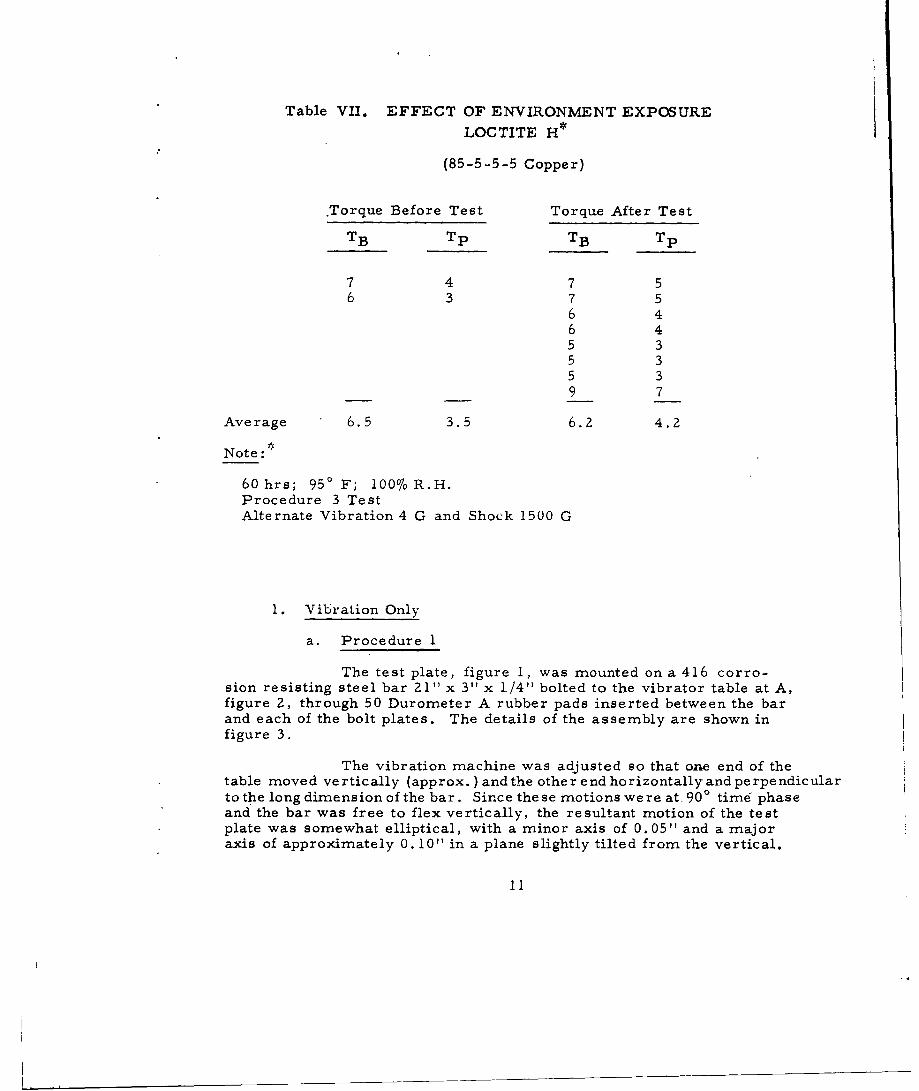
Table VII. EFFECT OF ENVIRONMENT EXPOSURE
LOCTITE H
(85-5-5-5 Copper)
Torque Before Test Torque After Test
TB Tp TB Tp
7 4 7 56 3 7 5
6 46 45 35 35 39 7
Average 6.5 3.5 6.2 4.2
Note:
60 hrs; 950 F; 100% R.H.Procedure 3 TestAlternate Vibration 4 G and Shock 1500 G
1. Vibration Only
a. Procedure 1
The test plate, figure 1, was mounted on a 416 corro-sion resisting steel bar 21" x 3" x 1/4" bolted to the vibrator table at A,figure 2, through 50 Durometer A rubber pads inserted between the barand each of the bolt plates. The details of the assembly are shown infigure 3.
The vibration machine was adjusted so that o-ne end of thetable moved vertically (approx.) and the other end horizontally and perpendicularto the long dimension of the bar. Since these motions were at 90" time phaseand the bar was free to flex vertically, the resultant motion of the testplate was somewhat elliptical, with a minor axis of 0.05" and a majoraxis of approximately 0. 10" in a plane slightly tilted from the vertical.
11

41
.00
VS
U -
124

~LU
o 4
L,0
-A
L I-LU4-
LU 0
LU0LI
- -
LUn
-IL
10 -
z u
Ui)
LU oL
1 0
LUICL Un
LU H ULUU
I- 4.0
cn
~N '
01

The applied vibration was programmed to vary continuouslyfrom 5 to 45 to 5 cps in 80 seconds periods. The plate acceleration asdetermined by an Endevco accelerometer was 4 G at 40 cps,
b. General Observation
No rotation of the unbonded screws was observed if vibra-tion was restricted to linear displacement.
All'unbonded screws invariably rotated when vibration re-sulted in circular or elliptical displacement. By reversal of displace-ment direction, the screws could be made to tighten or "walkout" withinless than 2 minutes.
No rotation of the LOCTITE H and LOCTITE E bondedscrews occurred.
2. Simultaneous Vibration and Shock
a. Procedure 2
The condition for this test was the same as for Procedure 1except that the Rockwell C55 hardened steel bolt B (fig. 2) was adjusted tostart contacting the impact plate C at approximately 28 cps (near reso-nance of the bar). This introduced a shock impulse of approximately 10 Gon the basic vibration acceleration of 4 G.
b. General Observations
All unbonded screws invariably "walked-out" within lessthan 2 minutes when the elliptical displacement was in the proper direc-tion.
No rotation of the LOCTITE H and LOCTITE C bondedscrews was observable.
No rotation of the unbonded screws was observed whenthey were turned down to finger tightness in the plate.
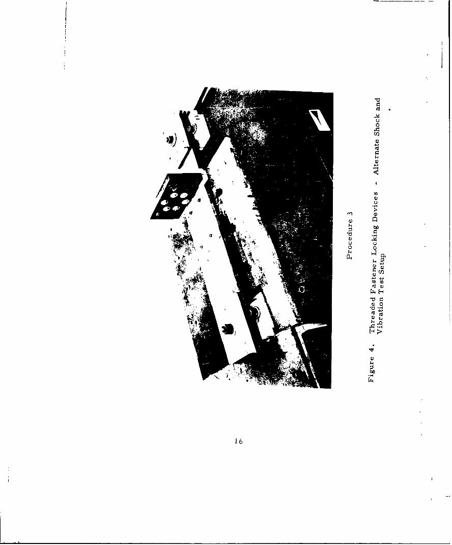
3. Alternate Vibration and Shock
a. Procedure 3
Because the results obtained with Procedures 1 and 2were inconclusive, a more severe test was improvised. The moment
14

of inertia of the screws was increased from 0.0127 x 10- 4 lb-in. 2 to0. 147 x 10-4 lb-in. 2 by the addition of two flat washers and nut asshown in figure 1. The assembled test plate was mounted on the vibra-tion bar as illustrated in figure 4.
The vibrator was adjusted so that the entire platformmoved simultaneously in two directions - (1) horizontal and per-pendicular to the screw axis, and (2) vertical and also perpendicularto the screw axis. The horizontal displacement was 900 out of timephase with respect to the vertical displacement. The table doubleamplitude displacement was 5/64". Due to the flexing of the vibrationbar, the motion imparted to the test screws was elliptic in a plane per-pendicular to the screw assembly axis about a center displaced fromthe screw axis by 0. 075" (major) to 0. 025" (minor) during the vibrationcycle.
Shock impulses were applied with the superstructureshown in figure 5 by allowing the 2 pounds striking weight A attachedto the 27 " radius arm to fall from the 900 position to the plate supportbracket C. The shock accelerations delivered to the test plate weredetermined with an Endevco Model 2213 accelerometer mounted on thetest plate. The values obtained after filtering the accelerometer out-put through a 10-1000 cps band pass filter were of the order of 1500 G.
The test plate was subjected to 10 cycles of alternatevibration and shock. Each cycle consisted of 5 minutes of vibration(5 to 45 to 5 cps in 75 seconds) followed by 10 pendulum deliveredshocks.
b. General Observations
All unbonded screws invariably 'walked-out' within 30-40seconds when the elliptical displacement was in the right direction.
An unbonded screw turned down with a cightening torqueof 2 in. -lb 'walked-out'' under these test conditions,
One bonded sc rcw exhibiting a prevailing torque of 1 in. -ozrotated approximately 30 degrees on each of the last 4 test cycles, Noother LOCTITE H bonded screws showed any tendency to "walk". Ex-posure for 60 hours at 100 ° R.H. at 950 F indicated no deterioratingeffect,
Tests made with Nylok (nylon insert) screws showed notendency to "walk" with prevailing torques ranging from 3 in. -oz to2 in.-lb.
15
4J
C)
C,,
16"-

Procedure 3
A - WeightB - Pendulum Radius ArmC - Plate Support Bracket
Figure 5. Threaded Fastener Locking Devices - AlternateShock and Vibration Test with Pendulum ImpactDevice in Place
17

A summary of the results is given below.
1. Original Characteristics
A plot of the relation between the breakloose and pre-vailing torques is shown in figure 6. The considerable variability ofthe data may be attributed to two factors - (a) the variability of theproperties of the cured material and (b) the nonuniformity of the pene-tration of the material as applied. No pattern appears which would in-dicate that any differences exist which may be attributed to the materialsurfaces involved in this investigation. When examined after the tests,it was discovered that the LOCTITE material covered only 8 to 11 screwthreads of the 16 thread engagement. In no case was complete penetra-tion observed. The prevailing torque (Tp) can be calculated approxi-mately from the formula 5
Tp = KD 2 L
where
K = 300-700 for LOCTITE H
700-1600 for LOCTITE E
1200-2800 for LOCTITE C
D = Mean diameter = 0.183 inch
L = Bonded length (8-11 threads) 0. 25"-0.34"
From this relationship, the following calculated values for Tp wereobtained.
Prevailing Torque - in. -lbTp
Calculated
LOCTITE 8 Threads 11 Threads Actual
H 2.5-5.9 3.3-7.7 2-8
E 5.9-13.4 7.7-18. 10-18
C 13.2-23.5 13.2-30.8 14-28
The calculated values agree very well with the range of values observed.
18

E ~ 9
E E
0 us z 0
LU 0I 0I2I48iv vi
0 0
o u u-1 j -1
g
C'A 4 uN9 u
sz 07z.
rU
ol 6L
8L AA UoLUW -j -4
91. >LU C
Lu EutL f4~14
_j 0 -4uz L0u 0~o QgAOL
LU 0
Oo100j
UN 4:0 00 C-
0
01
z HL
9l-1 NI - nfli oNIIVA38d - I

2. Shock and Vibration Effects
The breakloose torques and corresponding prevailing torquesmeasured after subjection to the shock and vibration tests are showngraphically in figures 7, 8, and 9. Here again the data is quite vari-able. These data all lie within the same maximum and minimum limitlines established by the original test data.
However, practically all of the test data obtained with thealuminum plates under Procedure 3 lie on the Tp = TB line. Thischaracteristic is not prevalent with the untested or the low shock testconditions. This may be interpreted as a loss of bonding caused bythe high shock conditions. The data cannot show if a loss in break-loose torque which should accompany this behavior actually occurred.The data obtained from all of the other tests do not show this charac-teristic.
Except for one test, the break and prevailing torques weresufficiently high to prevent "walkout". The one exception, possessinga prevailing torque of 1 in. -oz rotated 30 degrees during each of thelast 4 procedure 3 vibration shock cycles.
Exposure for 60 hours to 100% R.H. at 950 F appears tohave had no effect on the Tp and TB characteristics of LOCTITE H.
DISCUSSION
None of the test procedures used in this investigation were severeenough to cause loosening and "walkout" of bonded screws even thoughprevailing torques as low as 1 in. -lb were involved.
In this investigation, two distinct characteristics of the lockingcompound must be considered.
1. The first condition is the environment which would disruptthe screw-LOCTITE-base metal bond system.
Loosening of threaded fasteners is produced by simple fluc-tuation of tension. Goodier and Sweeney 8 experimentally demonstratedthe following theory. "When a bolt (with nut) is loaded in tension, thediameter contracts elastically according to Poisson's ratio. The nutexpands because it is compressed against its seat. During any increaseof load, the bolt thread is moving radially inward and the nut threadradially outward. Circumferential friction is required to counteract
20

IL-
I V V 0>
w uuu-
-J 00 4
00 I 0
7z
& wU
00
w61 wj
0 o 81 0
0u 0 a
91 u
Ow L
wu ow '
4~ L-
_j tU ZL
L WOL
40 6
0
44
_0 4-4
~ 0
-A c;
91 Ni - 3nomoi ONIIIVA?d- I

.0 so411U-4
-C,4
E2 u E3 LU - aUZ.a :
I E~
0 0
009z u
M- o
uJ I M
0 0 OZ
u4LIrl IIJ .
LU 0F- 0.
-~!L. 0
0. tn u -9 -c3ml 0 couLU <-0jOD0
1, 00
In 04
I LU 08
o00
i 1
0 L -4
-9 d91-NI~~c - f4O NIaA~

6E'BE.
p0 9EU0
o ;J
L~.0 IFCA -2 - j _ -_j
Uj eeu U w
0 8z~** *IE ~>±).~ O7zL
00 00 9z 0
o 0o 0,
0*5-
W 0?;6 I.-
LU
L 0
LUA
LUL
LU 00 6LI- 41
~ 0 944
LUL
LU
ui
S - NI - 3loOi ONIIIYAHd - 1
23

the loosening torque of the normal components of thread pressure.While the load is changing, therefore, the nut and bolt act as a re-versible screw mechanism. The pull in. the bolt causes rotation ofthe nut" if the resultant torque exceeds the counteracting frictiontorque.
When a shock impulse is applied in the direction of the screwaxis, a force is created between the screw threads and the base metalthreads due to the inertia of the screw assembly. This, according tothe theory, would create a circumferential force which may exceed thebond strength of the locking compound. With lock washers and similarholding devices, no prevailing torque exists after the bolting tensionhas been released. The screws will then be 'loose". With lockingcompound, the prevailing torque will exist as long as the screw is en-gaged with the base plate. This would account for equality betweenTp and TB after the high shock tests. Loosening will then be pro-gressive rather than sudden.
2. The second condition is the vibrational environment whichwould cause "walkout" after disruption of the bond or even cause bothbond failure and "walkout".
A study was made to analyze the test conditions to determine theexistence and magnitude of screw turning torques generated by the cir-cular orbit of the screw around the vibration displacement center axis.
In figure 10 is shown an instantaneous picture of the screw as-sembly and its relation to the displacement center.
Figure 11 is a diagram representing the essential features ofthe vibrating screw at some instantaneous position A at a displacementangle 0. The velocity V o of any point P on the radius of gyrationcircle, which can be considered to contain the mass of the screw as-sembly, will be
V o = 27rfr o ()
Where f = frequency of vibration or rotation, and
V s = V o cos p (2)
From triangle AOP
k2 r2d + r2 - 2rdro cos (c- 0)
and
rj = r2 + k2 - krO cos
24

0.1
RADIUS OF GYRATION CIRCLE
- SCREW HEAD
- SCREW THREADS
VIB3RATION /DISPLACEMENT /CENTER * .* .. *
SCREW AXIS DISPLACEMENT CIRCLE/
7SCALE -1/4 - .02
Figure 10. Threaded Fastener Locking Devices -Screw AssemblyRelative to Vibration Orbit
25

'4
0.0
bto
0 rm d
0 r- - f3 <
C a
~0O 03 >.- 0u D a1 (40 -4
c - c 4
0 > 0C. 41 t c ~ s
01 41-2 !: 2cC41ub 41 41u -0 E
E 00 u U
o J4>0 >
26

Solving for r o2 2
k 2 + 170 -
COB I -
2kr o
and ro ~kLRCosN- + V1- R 2 sin2 _] (3)
where Rrdk
and -Y = - 0
substituting in (2) for the condition R '0.5 and neglecting all terms con-taining powers of R above 3, we obtain
V s = fk R2 cos 2 - + 2 -R 2 +2Rcosy -R 3 cos , sin21
dVs 2and differentiating V s with respect to N and dividing (- ) by k,
dN
we obtain the acceleration of point P with respect to A.
a = 2f2k (2 ) sin3 y _ 6R 4 (2 +R2) sin 2N sin 4N)
f ( sin4 + 32
+ (4R 2 + 4R 4 + R6 X ' _ sin 2) 2R4( 1 sin 4- - -Y)2 4 4
+ 9R 6 sin 6 N + 24R 5 s in5
The total torque corresponding to this acceleration is the summation ofthe torques Tp at each point P around A.
2 =7r
ZTp = Z Iap
27
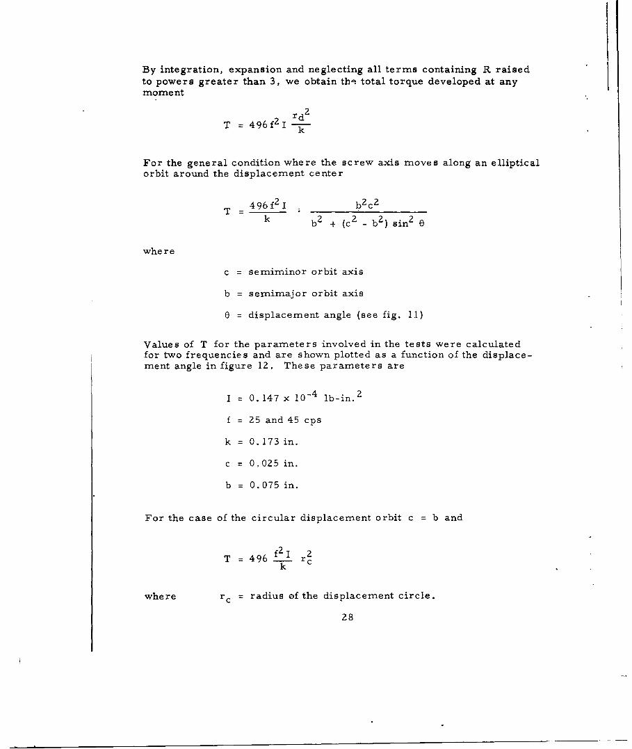
By integration, expansion and neglecting all terms containing R raisedto powers greater than 3, we obtain tbh total torque developed at anymoment
T = 496f21 r d 2
k
For the general condition where the screw axis moves along an ellipticalorbit around the displacement center
T 496 f 2 1 b2 c 2
k b2 + (c 2 _ b 2 ) sin2 e
where
c = semiminor orbit axis
b = semimajor orbit axis
0 = displacement angle (see fig. 11)
Values of T for the parameters involved in the tests were calculatedfor two frequencies and are shown plotted as a function of the displace-ment angle in figure 12. These parameters are
I = 0.147 x 10 - 4 lb-in. 2
f = 25 and 45 cps
k = 0. 173 in.
c = 0,025 in.
b = 0.075 in.
For the case of the circular displacement orbit c = b and
T = 496f2I rc2k c
where rc = radius of the displacement circle.
28

60 90 120.5 I , 1 8.0
4- f = 45 cps 6.4
u N48 0m 3- -4.80O
-J.3*I I
zz n
i I
o0
0.2- -3.2 oI. -
f=25cps.1 1.6
00 30 60 90 120 150 180
E= DISPLACEMENT ANGLE-DEGREES
Figure 12. Threaded Fastener Locking Devices - Developed"Walk-out" Torque as a Function of the VibrationDisplacement Angle Position of Screw
29
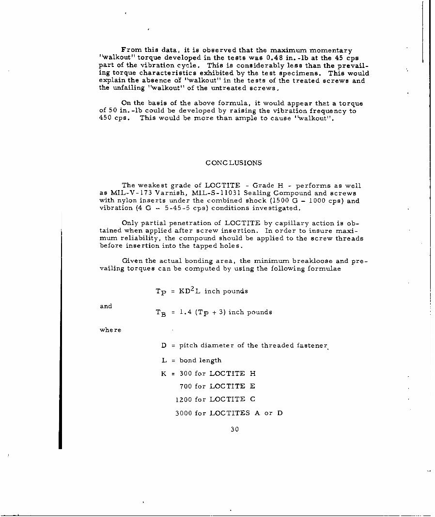
From this data, it is observed that the maximum momentary"walkout" torque developed in the tests was 0.48 in. -lb at the 45 cpspart of the vibration cycle. This is considerably less than the prevail-ing torque characteristics exhibited by the test specimens. This wouldexplain the absence of "walkout" in the tests of the treated screws andthe unfailing "walkout" of the untreated screws.
On the basis of the above formula, it would appear that a torqueof 50 in. -lb could be developed by raising the vibration frequency to450 cps. This would be more than ample to cause "walkout".
C ONC LUSIONS
The weakest grade of LOCTITE - Grade H - performs as wellas MIL-V-173 Varnish, MIL-S-11031 Sealing Compound and screwswith nylon inserts under the combined shock (1500 G - 1000 cps) andvibration (4 G - 5-45-5 cps) conditions investigated.
Only partial penetration of LOCTITE by capillary action is ob-tained when applied after screw insertion. In order to insure maxi-mum reliability, the compound should be applied to the screw threadsbefore insertion into the tapped holes.
Given the actual bonding area, the minimum breakloose and pre-vailing torques can be computed by using the following formulae
Tp = KD 2 L inch pounds
andTB = 1.4 (Tp + 3) inch pounds
whe re
D = pitch diameter of the threaded fastener
L = bond length
K = 300 for LOCTITE H
700 for LOCTITE E
1200 for LOCTITE C
3000 for LOCTITES A or D
30

The compound showed no sign of aging during the period of thisinvestigation. After 12 months, under uncontrolled room conditions,no change in the capabilities of LOCTITE could be observed.
The compound showed no evidence of significant "set up" withinthe first 30 minutes thus allowing ample time for adjustment.
The test conditions are not sufficiently severe to quantitativelydetermine the vibration "walkout" limits of threaded fasteners. Onthe basis of an analysis, it appears that the design of test equipmentto accomplish this is feasible. From this analysis, it has been de-termined that the "walkout" torque developed on a screw under ellip-tical vibration is
496 f 2 1 b2 c 2
T = ___ in. -lbk b 2 + (c- - b2 ) sinZ 0
where
f = vibration frequency, cps
I = moment of inertia about the screw axis, lb-in.2
k = radius of gyration about the screw axis, in.
b = semimajor vibration amplitude, in.
c = semiminor vibration amplitude, in.
e = displacement angle
Thus the torque may be adjusted by variation in frequency, variation invibration amplitude, and variations of I and k of the screw. On thebasis of this relationship, it was determined that the effective torquesdeveloped during these tests were well under 0.5 inch nound which isconsiderably below the prevailing torques measured.
31
RE C OMME NDAIONS
LOCTITE Grades A to H carA be used for antivibration andshock locking threaded fasteners in lieu of the present "dab" materi-als MIL-V-173 varnish and MIL-S-11031 sealing compounds. Theseshould not be relied upon for fastening under high frequency, highamplitude vibration conditions.
LOCTITE Grades A, C, and H will fulfill most of the designrequirements. These are adequately covered under Military Specifi-cation MIL-S-40083(ORD), although a vibration performance test re-quirement would be desirable.
When used, these materials should be applied to the threadedfasteners prior to insertion. Application after insertion is unreliableand should not be encouraged.
There is a need for an adequate neans for evaluating lockingmethods. it is recommended that a program be initiated to verifythe relationship between "walkout" torque and circular vibration fre-quency and amplitude developed in this report.
32
BIBLIOGRAPHY
1. Antivibration Lock for Screws - E. R. Levin, FrankfordArsenal Technical Report M53-24-1, 25 May 1953.
2. Fastener Locking Compound 3M Exp. 167437 Cement - E. R.Levin, Frankford Arsenal Technical Report M53-24-2,13 July 1953.
3. Antivibration Lock for Screws - E. R. Levin, FrankfordArsenal Technical Report S-4044, 17 September 1954.
4. Liquid Thread-Locking Agents - R. H. Kreible, MachineDesign, 29(19) 129-134, 19 September 1957.
5. LOCTITE Sealant - Technical Report #5, 1957, AmericanSealants Co.
6.. Vibration Resistance of Thread Locking Devices - K. R. Bronsonand C. C. Faroni, Product Engineering 31, 58-61, 10 October1960.
7. Evaluation of LOCTITE, Stopnuts and Lockwashers Under ShockLoads LOCTITE Technical Data Sheet TDS 8, 18 November 1959,pages 5-10.
8. Loosening by Vibration of Threaded Fasteners - J. N. Goodierand R. J. Sweeney, Mechanical Engineering 67(12), 798-802,December 1945.
33

DISTRIBUTION
27 Commanding OfficerFrankford ArsenalPhiladelphia 37, Pa.Attn: 5500, M. J. Oulton (5)
1500, W. T. Abell (1)1252 (15)1010, E. R. Rechel (1)1100, J. M. Thress (1)1400, H. Manning (1)1600, G. S. Van Dyke (1)1700, J. J. Cummings (1)6000, R. F. Keys (1)
1 - Commanding General 1 - Commanding OfficerArmy Rocket and Guided Missile Signal CorpsAgency R&D LaboratoryRedstone Arsenal, Alabama Fort Monmouth, New JerseyAttn: ORDAB Attn: Materials Div.
1 - Office, Chief of Ordnance 1 - Ord Materials Research Office
Department of the Army Watertown Arsenal
Washington 25, D. C. Watertown 72, Mass.
Attn: ORDTX 10 - Armed Services Tech Info Ag
1 - Attn: ORDTB Arlington Hall Station
Arlington 12, Virginia
1 - Commanding General 1 - Commanding General
Ord Tank-Automotive Command Diamond Ordnance Fuze LabsDetroit, Michigan Washington 25, D. C.Attn: ORDMC-RM3 Attn: Tech Ref Section
I - Commanding Officer 1 - Commanding Officer
Rock Island Arsenal Picatinnv ArsenalRock Island, Illinois Dover, New JerseyAttn: Lab., Mr. Harrison Attn: Tech Group
34

14C
I- E
"F' u - r
0 - - 7iH' -7 9
- ~ ~ -a
-~ce 0- v0-
0~~ t
F- 1>4 -6'
2 o 0 '3% "4- ~<

C -, C
-v - = C
<0 .
- -
C -, ~ ~ -~C -.
C C
~ - C C 0. (j~
d .~ C
-~
-~ ~ ~ -~
o .- 0 -~ 00 ~
z ~ Uz
-z.
- -~ -~ - COC-,o
OCt t0~
00 C OCt 00~Ct: ~
*~*0
Ct 0 t~O
-- ~-Ctt-
0.7~ '.CO~Ct0CC0~
C, '-C -C Ct- ~ -
toC~ o
-~ S
~' ~-' ~
U < C~t ~oU ~, tC'~
0<
CC,
CC
C) .4
Z Z '-~ C)
- U - 0 Ct
I, t ~ ~
tC ~ -- ~-.~ e
~ . -St.0/ -~o <
U ~. C -
< -<~ ~ ~-c Ct~.. LC CtC CC
Ct tC~ .).0 CtC, CC CC 0 '.'..oC O~ CCCC t.U 0
.CU
C..C <C'CC 0 oCt CL'..
-- ~
<C U ~<0 C~ ~CJOO .0C ~
0
~ ~0 c