ad 291664 - defense technical information center · ad 291664 reproduced ... the former was chosen...
TRANSCRIPT
UNCLASSIFIED
AD 291664 Reproduced
iu Ute
ARMED SERVICES TECHNICAL INFORMATION AGENCY ARLINGTON HALL STATION ARLINGTON 12, VIRGINIA
UNCLASSIFIED
NOTICE: When government or other drawings, speci- fications or other data are used for any purpose other than in connection with a definitely related government procurement operation, the U. S. Government thereby incurs no responsibility, nor any obligation whatsoever; and the fact that the Govern- ment may have formulated, furnished, or in any way supplied the said drawings, specifications, or other data is not to be regarded by implication or other- wise as in any manner licensing the holder or any other person or corporation, or conveying any rights or permission to manufacture, use or sell any patented invention that may in any way be related thereto.

«V 5r-/-^
CO H
£Q
'- c.
c 1
00 I o
ä o
B
IISEIII REPORT NO. Ä60-8
FABRICATION OF THIN WALLED SHAPED CHARGE LINERS BY POWDER METALLURGY
by
F. I. ZALESKI and
R. A.' POWELL
QEC 161962
OMS Code 5010.11.807 DA Project 59332003
FRANKFORD ARSENAL Philadelphia, Pa. October 1960
Requests for additional copies are to be made to Armed Services Technical Information Agency (ASTIA), Arlington Hall Station, Arlington 12, Virginia.
The findings in this report are not to be construed as an official Department of the Army position.
FRANKFORD ARSENAL Research and Development Group Pitman-Dunn Laboratories Philadelphia 37, Pa.
REPORT A60-8 October 1960
FABRICATION OF THIN WALLED SHAPED CHARGE LINERS BY POWDER METALLURGY
Prepared by:
F. I./Z^LESKI Metallurgist
R. A. POWELL Metallurgist
Reviewed by:
H. MARKUS Chief Metallurgy Research Laboratory
Approved by: JP£ A. L/'JAMIESON Deputy Chylef Research Division
A \^
FOREWORD
This paper was presented at the Powder Metallurgy Symposium during the 42nd National Metal Show held in Philadelphia, Penna., on 19 October 1960. The symposium was co-sponsored by the Metal Powder Industries Federation and the American Society for Metals.
The paper was distributed nationally to the membership of the Metal Powder Industries Federation as the "Paper of the Month."
ABSTRACT
A unique powder metallurgy method was developed for producing dimensionally acceptable high density shaped charge liners from cop- per powders for the M28A2 rocket. The problems involved in tool design and processing of this thin walled cone are discussed.
A number of cones were produced to the specified dimensions from various commercial copper powders. A powder with good flow characteristics appeared to be the main requirement. This insured a uniform fill of powder in the die cavity, provided good dimensional control and minimum density variation in the cone.
The best combination of properties was obtained on cones pro- duced from copper powders containing approximately 40 to 60 per cent fines (-325 mesh) and sintered at 1650° F. The average den- sity of the finished cone was 8.4 gm/cc, which is 94 per cent of the theoretical density of copper. Typical tensile properties of these cones were 30,400 psi tensile strength and 31 per cent elon- gation.
in.
FABRICATION OF THIN WALLED SHAPED CHARGE LINERS BY POWDER METALLURGY
INTRODUCTION
The powder metallurgy process has proven to be an advantageous and economical method of fabrication of many simple and complex shaped components for military and commercial applications alike. Although this process is particularly well suited to mass production, experience has shown that quantities of only several hundred pieces can be made economically providing tool and setup costs are not unreasonably high.
In the case of the shaped charge liner used in military ammunition, the purpose was to develop a method of producing this thin welled cone and to study its ballistic performance in comparison to a drawn copper cone. The economy of the process was considered secondary. Additional justification for the establishment of the program was that copper powders were readily available from a number of suppliers and that cop- per powder metallurgy techniques were widely known. The development of a suitable technique on a laboratory scale for the production of cones also offered the possibility of producing cones of various alloys not possible by other methods.
The program that was established called for the production of a sintered copper liner using the powder metallurgy research facilities of the Frankford Arsenal. Should the cones produced from copper pow- der meet the ballistic requirements, the process developed could be translated from a laboratory scale to production.
EXPERIMENTAL PROCEDURE
Liner Dimensions
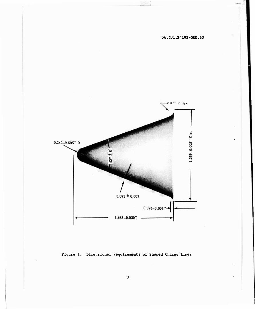
The dimensions and allowable tolerances of the liner were es- tablished by the requirements of the projectile. These dimensions are shown in Figure 1. This is a simplified drawing of the cone and omits details and notes.
Tooling
The tooling required for the fabrication of a thin walled cone presented several unusual problems.
One obvious fact is that a cone is a departure from the usual shapes produced by conventional compacting. The most serious depar- ture is that the wall of the cone is thin and not normal to the
i
36.231.S4193/ORD.60
D.02" R
0.34O-0.O05" R
Figure 1. Dimensional requirements of Shaped Charge Liner
direction of pressing. Consequently, during the pressing cycle the forces are tending to cause a rolling action among the particles rather than the usual mechanical interlocking and cold welding of the parti- cles which are necessary to produce sound compacts.
Another important consideration was the method of filling the die cavity with metal powder. In the conventional method, the die cavity is filled with powder flush with the top of the die and some rearrange- ment of the powder occurs during the pressing cycle, depending upon the contour of the upper punch. Preliminary experiments showed that this technique could not be applied to this cone as the results showed a nonuniform distribution of powder. It was also found in these experi- ments that this condition could be minimized if, prior to powder fill, the two punches were brought together inside the die to form a cone shaped cavity of the necessary volume. Although the die cavity formed between the two punches could be filled either through the flange or the apex of the cone, the former was chosen for simpler tool design. It was also felt that filling the cavity with powder through the flange would provide for easier flow and, if necessary, tamping of the powder.
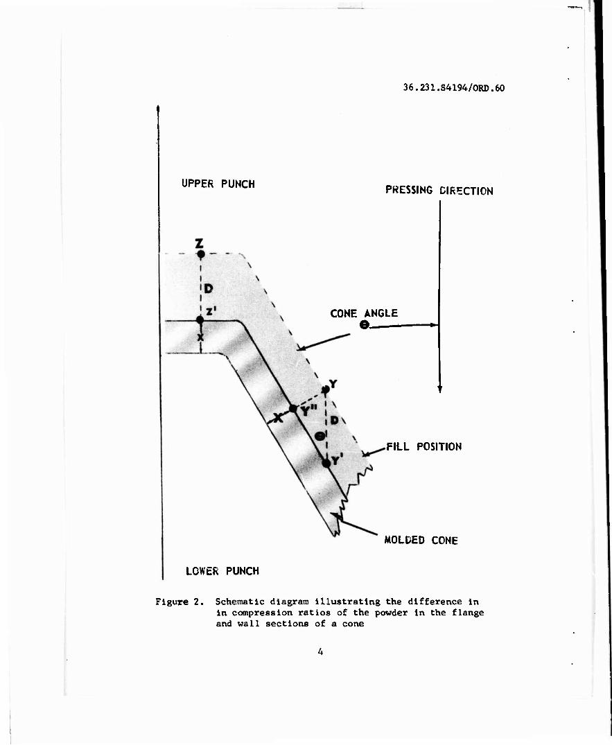
Another consideration in the tool design was the difference between the compression ratios, and consequently the densities, of the flange and wall if the thicknesses were kept the same. The differences in com- pression ratio in these sections can best be explained by the diagram in Figure 2.
In this diagram, the fill position of the punches is shown. Upon compaction, the punches move together to form a cone with a uniform wall and flange thickness, X. A point Z on the flange and a point Y on the wall of the molding surface of the upper punch move a distance D paral- lel to the direction of pressing and assume new locations Z' and Y1, respectively. The cone angle measured from the pressing direction is e.
The compression ratio is the ratio of the volume before and after pressing; however, in the case of parallel molding surfaces, such as in the cone, there is no change in the pressing area so that the compres- sion ratio may simply be stated as the ratio of the original to the final thickness. In the case of the flange, the original thickness is X + D. In the case of the wall, although the point Y has moved to the new location Y', the original wall thickness has been reduced not by the distance D, but by the distance between the points Y and Y'. This distance is a function of the cone angle 0, and may be defined as D sin 6. From the above analysis, it is apparent that the compression ratios
are X + D in the flange, and X $ j? sin 0 in the wall. It can be seen X X
by a comparison of the compression ratios that the only time there
36.231.S4194/ORD.60
UPPER PUNCH PRESSING DIRECTION
CONE ANGLE e. »
FILL POSITION
MOLDED CONE
LOWER PUNCH
Figure 2. Schematic diagram illustrating the difference in in compression ratios of the powder in the flange and wall sections of a cone
would be an equality is when the sin 0=1 which is at 90°. Since, in the case of a cone, sin 0 is always less than 1, the compression ratio of the powder in the flange will always be greater than in the wall.
It is possible to have equal compression ratios in these sections by increasing the flange thickness; however, the flange would have to be machined to dimension after sintering and prior to sizing. With this sintering and prior to sizing,
mpression ratio becomes Lf r new flange thickness X', the compression ratio becomes a-*~M, in the A
flange. This compression ratio can then be equated with the compression ratio in the wall
X' + D _ X + D sin 0 X' X
(1)
which reduces to: X' = -£_ (2)
sin "3
For this particular cone, the thickness X is equal to 0.0930 in. (average) and the cone angle 8 is 21° (sin 21° = 0.35837). Then, by sub- stitution into equation 2, the flange thickness can be found to be 0.260 inch.
A final consideration was the sizing of the cone after sintering. Past experience in the sintering of copper indicated that sizing would be mandatory to meet the specified tolerances.
In an effort to minimize both the initial tooling costs and the number of operations in the fabrication of the cone, it was decided to mold a cone with uniform flange and wall thickness despite the large difference in compression ratios since these tools could be used for both molding and sizing.
Powder Conditioning
Eight commercial copper powders were used in the molding experi- ments. The principal differences in these powders were the methods of production and the particle size distribution. A number of standard powder and die lubricants were also used. These included various stearates and paraffins in the dry form, dissolved or as suspensions in organic solutions. These lubricants were blended with the powders, coated on the molding surfaces of the tooling, or a combination of these.
Pressing
A dual ram hydraulic press with a maximum capacity of 200 tons was used for molding the thin walled cone. Under manual control, this press can be started or stopped as required, with independent control over each motion. Pressure may be applied with the top and bottoms rams, either simultaneously or consecutively.
"I
Sintering
Sintering of the molded cones was accomplished in a pusher type furnace with an 8 in. x 12 in. Inconel muffle. The furnace is heated with globar elements and has a uniform hot zone, 22 inches in length.
The cones were sintered in this furnace at temperatures between 1300 and 1800° F in an atmosphere of dissociated ammonia. The purpose of these experiments was to determine the optimum sintering temperature at which the cones would undergo a minimum of shrinkage and still have sufficient ductility to permit sizing without cracking.
DISCUSSION AND RESULTS
Tooling
Several cones with uniform flange and wall thicknesses were molded. An examination of these cones showed very fine cracks at the junction of the flange and the. wall. It was felt that the chief cause for these cracks was the high density gradient at this junction. All efforts to eliminate these cracks with this tool design were futile.
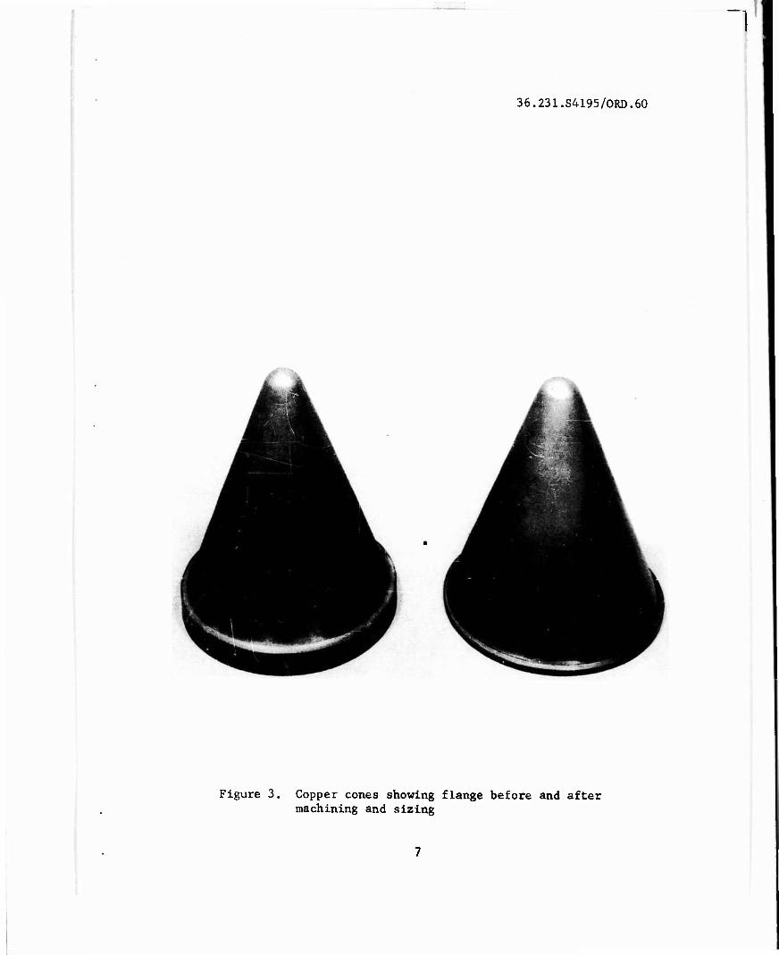
It was necessary at this point to have another upper punch fabri- cated which would allow for a deeper fill in the flange section, and thus provide for a uniform density in the flange and wall. Cones, free of cracks, were molded with this tool set; however, as previously men- tioned the flange had to be machined prior to sizing. Figure 3 shows a sintered cone before and after machining and sizing.
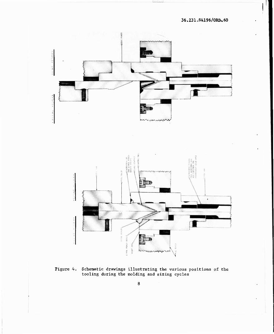
A schematic drawing of the tooling that was designed and fabricat- ed for the molding and the sizing of the cone is shown in Figure 4. One view shows the filling and molding positions of the tools while the other shows the ejecting and sizing positions. The die is attached to the lower ram and not to a stationary die table is it is normally. A guide ring occupies the normal die position. A movable die is required to utilize the flange fill method. The correct fill is obtained by bringing down the upper punch to a positive stop and adjusting the height of the lower punch insert by means of the fill adjusting rod (stationary core rod) within the lower ram. After filling the cavity, the excess powder is cut off by raising the die. As the die continues to rise, the lower punch insert "bottoms" in the die. At that instant pressure is applied to both rams and the pressing cycle is completed. The lower ram is then retracted until the flange of the cone is eject- ed from the die. The briquette can then be lifted easily from the lower punch. The sintered cone was sized in a manner similar to molding.
36.231.S4195/ORD.60
Figure 3. Copper cones showing flange before and after machining and sizing
36.23X.S4J.96/ORIk60
l"-",-''%'wN/v*/> ,^^v^AAvV/
, i
£ ' ' ? i
£ * fe^w
N
Figure 4. Schematic drawings illustrating the various positions of the tooling during the molding and sizing cycles
8
In the sizing position, note the flange addition to the upper punch. This was the final design of the upper sizing punch which provided for a positive stop by making contact with the top of the die. The stops built into the rams of the press could not be used to maintain the close tolerances of the finished cone.
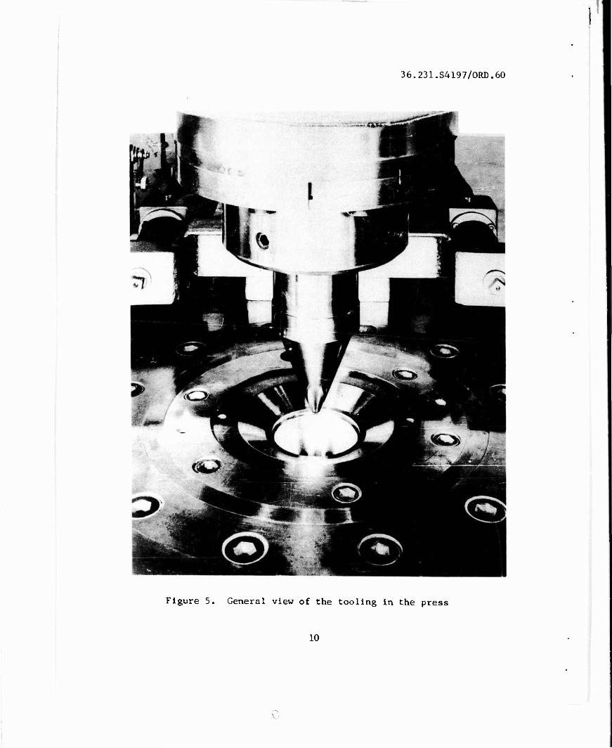
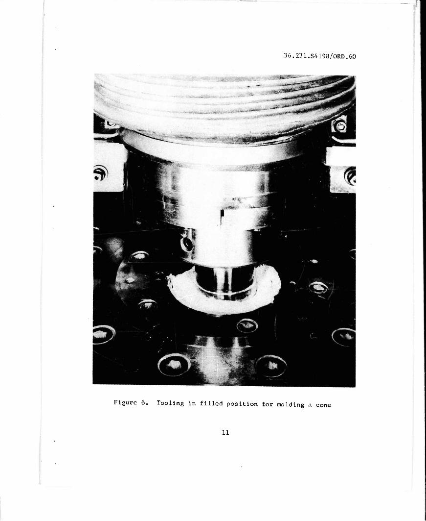
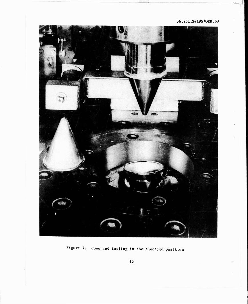
Figures 5, 6, and 7 show the tooling at various scages during the molding cycle.
Powder
Although cones could be molded from all of the copper powders, the density gradients differed significantly. It was found that powders with good flow characteristics resulted in the least variation in green density throughout the cone. Various lubricant additions to the metal powders did not significantly reduce the density gradient; however, it was found necessary to coat the molding surfaces of the punches to facil- itate removal of the ejected cone from the die.
Pressing
Loads from 100 to 175 tons were necessary to mold cones with suf- ficient green strength for handling. However, in an effort to minimize the changes in dimensions that occur during sintering, the highest load (175 tons) was used in most instances. The green densities obtained with this load were comparable to those normally obtained on standard specimens with compacting pressures from 12 to 15 psi. Although these compacting pressures were below the optimum pressures for achieving high density copper compacts, they could not be increased due to the limited capacity of the press.
Sintering
Shrinkage and some distortion occurred in all the cones and varied with the sintering temperatures. With some of the cones the shrinkage was found to be excessive. Supporting the cones with alundum grain minimized the distortion; however, due to the insulating properties of the grain, the total sintering time had to be increased considerably.
Dimensional Control
An important consideration in maintaining dimensional control of the cone was to minimize the amount of shrinkage that occurred during sintering. It is known that the amount of shrinkage of copper compacts varies mainly with Compacting pressure and sintering temperature, and
36.231.S4197/ORD.60
Figure 5. General view of the tooling in the press
10
36.231.S4198/ORD.6.0
Figure 6. Tooling in filled position for moldi ng a cone
11
36.231.S4199/ORD.60
Figure 7. Cone and tooling in the ejection position
12
is related to the particle size distribution of the powder. Due to the limited press capacity only the sintering temperature and the particle size distribution of the powder could be varied. The best combination of properties was obtained with powders containing between 40 to 60 per cent fines (-325 mesh) and a sintering temperature of 1650° F. The den- sity of these compacts increased from 6.5 to 7.6 gm/cc during sintering.
Sizing
Early in the sizing experiments, failures in the form of cracks appeared near the flange of cones which had excessive shrinkage. These cracks were attributed to the severe-amounts of cold work required to size this section. This was not a problem with cones with low shrink- age.
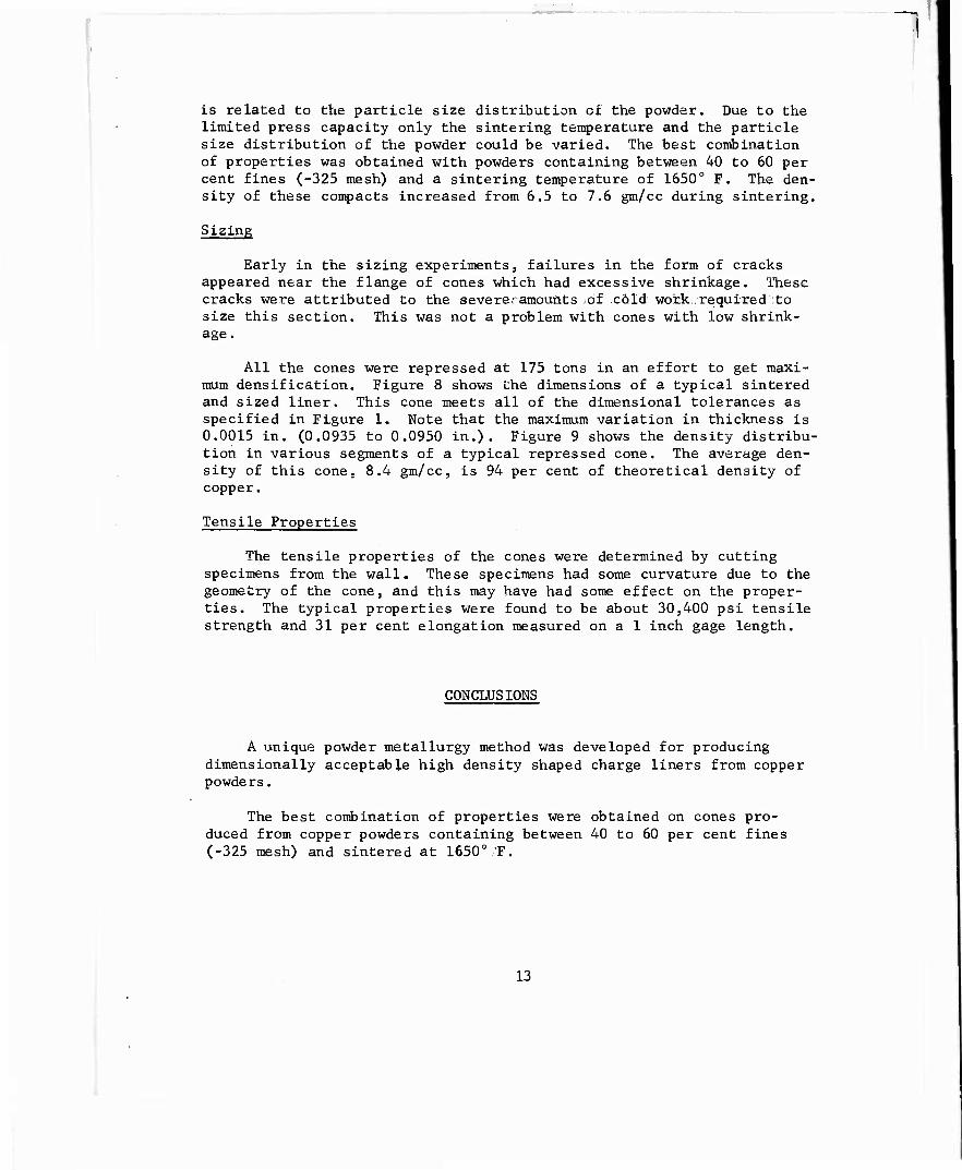
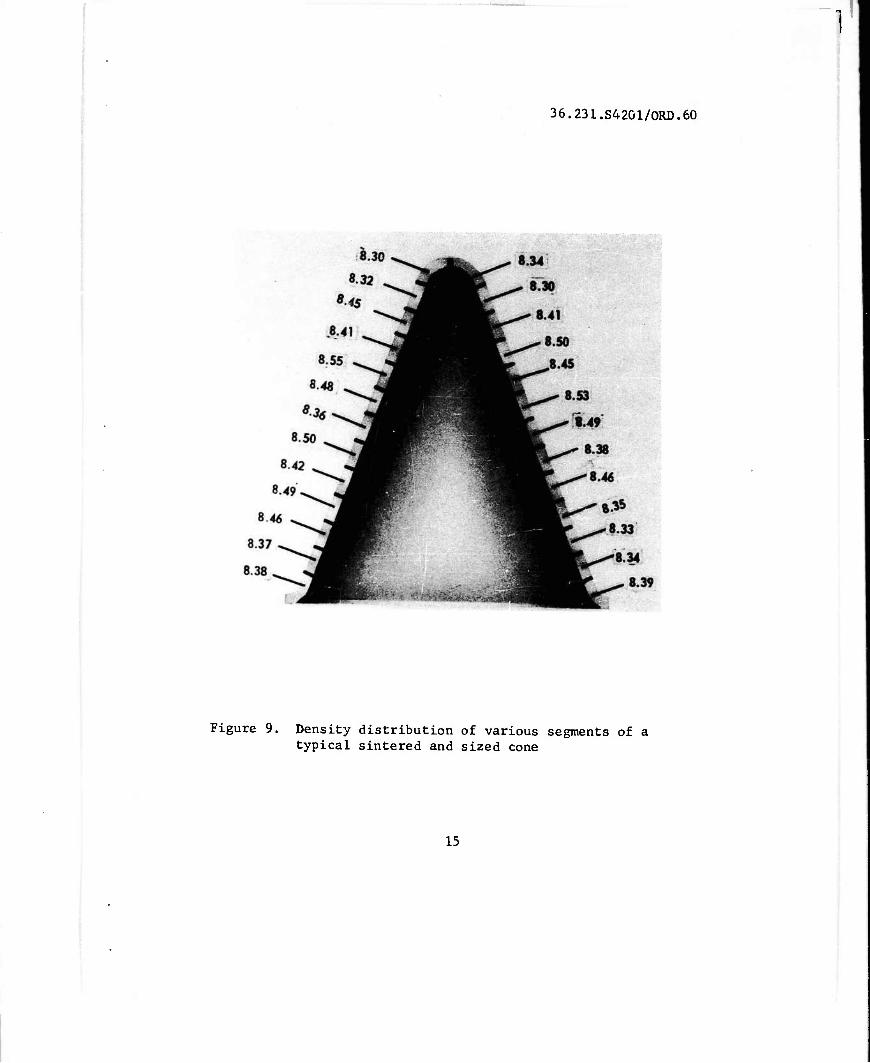
All the cones were repressed at 175 tons in an effort to get maxi- mum densification. Figure 8 shows the dimensions of a typical sintered and sized liner. This cone meets all of the dimensional tolerances as specified in Figure 1. Note that the maximum variation in thickness is 0.0015 in. (0.0935 to 0.0950 in.). Figure 9 shows the density distribu- tion in various segments of a typical repressed cone. The average den- sity of this cone. 8.4 gm/cc, is 94 per cent of theoretical density of copper.
Tensile Properties
The tensile properties of the cones were determined by cutting specimens from the wall. These specimens had some curvature due to the geometry of the cone, and this may have had some effect on the proper- ties. The typical properties were found to be about 30,400 psi tensile strength and 31 per cent elongation measured on a 1 inch gage length.
CONCLUSIONS
A unique powder metallurgy method was developed for producing dimensionally acceptable high density shaped charge liners from copper powders.
The best combination of properties were obtained on cones pro- duced from copper powders containing between 40 to 60 per cent fines (-325 mesh) and sintered at 1650° F.
13

1
36.231.S4200/ORD.60
0.340R
— 0.0950 „^ „ 0.0940
0.0955^^ |^. 0.0940
0.0955 ^0.0935
0.0950 p' H L ^00940
0.0955 J L^*f^^l
I 0.0940
656 0-0950 jH Bö- ■ m" 0.0950
0.0955^^ jF' ̂ ^42° ±51^ TJ_^ 0.0950
0.0955^^ Im- ^T 0.0950 °0950^,^ y m^ 0.0945
0.0945,. JP f.' C-935 *JF
^fc^ 0.0945 .ar ^ 0.0940
J.092J
1
3.359 ■ l r^ •
9L\* 0.0935
-^■f — 0.010"R ^^L
t 0.094 Dm
Figure 8. The dimensions of a typical sintered and sized cone
14
36.231.S42G1/ORD.60
Figure 9. Density distribution of various segments of a typical sintered and sized cone
15
fc m
The average density of a finished cone was 8.4 gm/cc, which is 94 per cent of the theoretical density of copper. Typical tensile proper- ties of these cones were about 30,400 psi tensile strength and 31 per cent elongation.
16
DISTRIBUTION
_ I
1 - Hq, U.S.Army Materiel Command Department of the Army Attn: AMCRD-DE-W Washington 25, D. C.
1 - Attn: AMCRD-DE-MO
1 - Commanding General UJS.Army Munitions Command Picatinny Arsenal Dover, N„ J.
1 - Commanding General Picatinny Arsenal Attn: Laboratory Dover, N. J.
1 - Commanding Officer Springfield Armory Attn: Engineering Dept Springfield 1, Mass.
1 - Commanding Officer Rock Island Arsenal Attn: Laboratory Rock Island, Illinois
1 - Director Ordnance Materials Research
Office Watertown Arsenal Watertown 72, Mass.
1 - Commanding Officer U.S.Army Research Office -
Durham Box CM, Duke Station Durham, N. C.
1 - Commanding Officer Diamond Ordnance Fuze
Laboratories Attn: Technical Reference Br Washington 25, D. C.
10 - Armed Services Technical Information Agency
Attn: TIPDR Arlington Hall Station Arlington 12, Va.
1 - Commanding Officer Watertown Arsenal Attn: Technical Group Watertown 72, Mass.
1 - Commanding General U.S.Army Test & Evaluation
Command Attn: Laboratory Service Div Aberdeen Proving Ground, Md.
1 - Attn: Ballistic Research Lab.
1 - Attn: Development & Proof Serv.
2 - Attn: Technical Library ORDBG-LM
17
a w h Hi •n < A U Z u
a s Si
• * M •* k
CO » -* V
3 a 5 £ <C N PA O
1-4 H H > M H H
a u
■<
u z a
o H
lx <■*
10 0) •< J U Z Ö
e$22 - -s { -.o ) <H O
8 3 ! < N (
M -O U -H O a <P T3
O >»ey <
ei Tt to ■•
Cj C JE '
U 1' i t-n a) i » w iw es 3 -
U M O i-l o u u u -< u 0,-g .^
>t4J <M U
j n-i n o a r o OJ
« a ß gg o z
§ Ir-"
-5 -u u ai o • o oox a.
1 0> 00
•i to to
■D i-l W 01 O U ■ o u f4 U q M M M 3 00 C
u T* at e o
ii M (0 > 0) d
cvo a « <u •^^ Eb u<-<
00 H C
ss C 4J
) a) ID 4 TJ 0)
0 3 §
3 u ai 6 3 »H
-a n o -rj ^ a* I« 841
q <u « 4) 3 <N »
o) *J M a, M a at a»
I •ifi O. C *0 O
1 ü iw n M J= O 4) ^N a ■• a j3 ■-< >i at a » c u M O P >M «0 IJ
O S S M -lE h fi.-3 M -O
< e*ls J -0 M h -^
CO » H O
s||i ^ fill 9
5^
<
U z Ö
0 an u"1
1 1 -3 S -
8 SS
O 111 OJ XI
nj u 4) ■O ä p H
Qj w lJ tfl
o >.M ec u S d > B) N n v c X »
■O 4) U n J= o
»oo a ■rl U
•a X o *B O *w C Jl 4) « u-( a aj x> ^ c B o a «j
>.&> » bo 41 O V M u a-o 3 u
-H « M H i-i «I O ffl X cu O
Srj o 4UC
13 D, 41 3 A J3 O
•o «4 4J a^« 4) P •A ai M-i i- U-l • J O 4J -H (0 ä U M O r* O o OJ 4J -J o
W f T3 'W rH 0 41 _ t«
at a fi B c J3 «MO
<4-i n 4J
4) o
SO m '^
>4 ii ^, u u u « C *J a o c JJ i-< -H M o JJ >W ■ O W r-4 O Q 41 0) 4)
ab'Q u UK S3 h in
v v «in
' 9* 9* O. to §s I U 4 U O T) i u u a ■ Q u u-i a« a
■-J w4 __ y V K Kf3u a n u-o-a j ap <f -A oo 'Oi-iiauouoM >o< a a p ü •* h o b ah *-' a « hMb^ooaaa «IM 0.414)« «-< lOoUUU
BUCH IM o o a 4) B U -rl 01 C O MlflSrl Moat « o d« a « «i 41 O bl 0>-^>M C ^ -J ft U H 5 «*4>UOC -rt-M
tOJSjSp « -^ -4 4J -* p.« J I p C -4 4J « < -Kö
0, M « U 00 H V -n C CD u
• fr, > -M O 41 M "• — -J « O U fa 4 >i-l
to 3
o M 5
L S W O ■^ w >
j T3 g a
<H IM Sj>JJO«U MO.
> SoSua at -4 a do a MM OH du*Sao ap
■M U <M b0-H 4) 4) tfl 3 <J 0 ?
tu a tS g
g -r4 I 3 (j uj a
3 OOr-t < -O M Jl
4 41 « a - — . .o a. d "o c
(0 4> M-l ( 1 3 du ii 0 «««Men -OCO-riH4l3a)M u30
3 i-S |51 8 tit i
wn u p I H 01 O
-O *-/«w * jS -4 aoouu
tt 1-1 I g-H IB >s M «M CHI
... g 3 3 5 e ° g ■M ja «M n o « ■-• «-t -' o ei at a) oi
o ii 3 So M < ■ JZ
M O.*^ g <U
U W 4J S*ft. . - a T3 <M O W *
6 «•<-<•**- .J >? a,« C *H u « « • K 3 O.M «J*J_C0|M C
• is > -^ 5 ai » •I U JD U U I • -4
H > U S « U MO.
M d ui n 5 g.5 3 ■* tl O O U 8 *
fi « I « M jS O
to m H u
S-3 IS < N P- a
l§ BIN ^2
I 5« ,2
3E£ 8ft
8 n 'I M ai -a oi 3 d zr oo i-i i-i c H d -4
o M d ** "C i a)4-ioo-<ojaito3
U3 3 ij -9 41 O *2 I » ja o"t) ja a. a f
'. a Sä g
3 60 -
O (0 O ' M ,d M :
cuaitido-HMv a w ■* H o.^: -w
a « c ■ u 6 "
a w
<
o z Ö
a w
10
<< J o Z

u o
■o u u ^ tjl « a CD M rH u
111 ials 1 ri ■Saa
s i si H V
J e
§ h il 1:
-3M
2
is ö 'S ö'
SB •a Sa
M -O W -J
■sIsS
* 3 § « aj a X »
•a j o 's o w q
i-i a o w * ft. o W H E w UH e Sl f{ I 8 1
i;JJ
TJ < U s g
U U fl O -H
•aas g g" a. " s s
laül 1 ■ •M m u a
i H u 5 "3 *^tw « ja -H Sc O w *J
■ -H a
s 55"B° § o I 5 v «
Q S w 3 83
s}Jl C 65 A« to p
ofl
00 CO iH O
3dl8 P-I N m ■# IÖB
l*H Uli
3 & 3 J J?
n ON 3 a
a «-irr!« © O «
f?*ss
illh i im :m
1;
«fa
ifi;-*s "28S3 .-
Iiljih nVh* I JI3-S»
! 3]i
UJf3 u X D
»* w «n V
,|al Uli -agfc
I «9
u z p
ÜSüJ »M rt *3
o ö Q u
ahfcl ä <w 3 o w *->
'S OB««»
S si"««
Jsssf'S5! "0 M < at J3
iJiHil
ale IS M ! S Hf J
T, „is
4« it I Is 3«
i] Iri
as «'s
*IiK
1<8S 3 .«I lw??_
I i PH III Hi1 i»l 11 «h
i «II -ial
-'age
i 3* II
hi!} " I 3
I «3 IISa 11*1 a .9 -o *• I • P
ff s* !Jfi
Hi fill Ifll «all If« Sill
'?];
"•III
■9 < « 5,— _ I «i ■
g.°2"s
II .ill
* ■ IM &
Sp'Vl
3 SlüffJli
*3 a *o IN a v • -1 i i TiJ «ii sl!:33;ihsj iJiMill^i] •B-j— 1 B 8 2 a ^ a» kIII »sl'lll •iajS-'oJIil'j^jj"
■ a u -* a a. « a w M
3 i«a-s-ä sas-ss
Q U
< o z s
o H
h. M to n < u z »