ad, 714, - dtic.mil · a review of hypersonic flow ... incremental aerodynamic heating rate due to...
TRANSCRIPT

UNCLASSIFIED
AD, 2 7 6 714,
ARMED SERVICES TECHNICAL INFORMATION AGENCTARLINGTON HALL STATIONARLINGTON 12, VIRGINIA
UI
UNCLASSI[FIED

NOTICE: When government or other drawings, speci-fications or other data are used for any purposeother than in connection with a definitely relatedgovernment procurement operation, the U. S.Government thereby incurs no responsibility, nor anyobligation whatsoever; and the fact that the Govern-ment may have formulated, furnished, or in any waysupplied the said drawings, specifications, or otherdata is not to be regarded by implication or other-wise as in any manner licensing the holder or anyother person or corporation, or conveying any. rightsor permission to manufacture, use or sell anypatented invention that =y in any way be relatedthereto.
/.

SASD TDR 62-168
A REVIEW OF HYPERSONIC FLOW• FSEPARATION AND CONTROL CHARACTERISTICS
CZ4'Il
Jý _,D Louis G. Kaufman, II Richard A. Omanrk-, - Stavros A. Hartofilis Lawrence H. Meckler
- William J. Evans Daniel Weiss
I GRUMMAN AIRCRAFT ENGINEERING CORPORATION
Contract No. AF 33(616)8130
MARCH 1962
TIS1C%•4 -T a
Flight Control Laboratory
AERONAUTICAL SYSTEMS DIVISION
AIR FORCE SYSTEMS COMMAND
WRIGHT-PATTERSON AIR FORCE BASE, OHIO
II

i ii
NOTICES
When Government drawings, specifications, or other data are used for any purpose
other than in connection with a definitely related Government procurement operation, the
United States Government thereby incurs no responsibility nor any obligation whatsoever; -
and the fact that the Government may have formulated, furnished, or in any way supplied
the said drawings, specifications, or other data, is not to be regarded by implication or
otherwise as in any manner licensing the holder or any other person ,or corporation, or
conveying any rights or permission to manufacture, use, or sell any patented invention
that may in any way be related thereto. -,
1 ]'
Qualified requesters may obtain, copies of this report from the Armed Services Tech-
nical Information Agency, (ASTIA), Arlington Hall Station, Arlihigton 12, Virginia.
This report has been released to the Office of Technical Services, U. S. Department Iof Corninerce, Washington 25, D. C., for sale to the general public.
Copies of ASD Technical Reports and Technical Notes should not be returned to the
Aeronautical Systems Division unless return is required by security considerations, con-
tractual obligations, or notice on a specific document. i
III
-t

ASD TDR 62-168I'
A REVIEW OF HYPERSONIC FLOW
SEPARATION AND CONTROL CHARACTERISTICS
iI Louis G. Kaufman, II Richard A. Oman
Stavros A. Hartofilis Lawrence H. Meckler
William J. Evans Daniel Weiss
I GRUMMAN AIRCRAFT ENGINEERING CORPORATION
1 MARCH 1962
Flight Control LaboratoryContract No. AF 33(616)-8130Project 8219 Task 821902
I
L AERONAUTICAL SYSTEMS DIVISION
AIR FORCE SYSTEMS COMMANDj UNITED STATES AIR FORCE
WRIGHT-PATTERSON AIR FORCE BASE, OHIO
I~

-I
FOREWORD
This is the first major report on hypersonic flow separationand control problems which are being investigated by the ResearchDepartment of the Grumman Aircraft Engineering Corporation. Thework is primarily supported under Contract AF33(616)-8130; AirForce Task 821902. The Project Engineer is Mr. Donald E. Hoak ofthe Flight Control Laboratory, Aeronautical Systems Division, lo-cated at Wright-Patterson Air Force Base, Ohio. Forthcoming re-ports will present the results of theoretical and experimental re- 1search being carried out under the contract.
ASD-TDR-62-168ii
I
ABSTRACT
1A comprehensive review of high-speed flow separation and a review ofavailable information pertaining to the effectiveness of aerodynamic con-trols for hypersonic vehicles are presented. Emphasis is on the problemsassociated with applying the existing information, which relates primarilyto the low-supersonic speed range, to hypersonic flow situations.Sufficient detail is presented to allow this report to serve as a self-contained, introductory work on separation phenomena; available sources ofspecific types of control data are tabulated for ready access.
iIIIii
PUBLICATION REVIEW
This report has been reviewed and is approved.
1 FOR THE COMMANDER:
Chief, Aerospace Mechanics Branch
Flight Control Laboratory
ASD-TDR-62-168iii
L
TABLE OF CONTENTS
I term PageI n t r o d u c t i o n . . . . . . . . . . . . . . . . . . . . . . . . . . . . 1
Hypersonic Flow Separation........................... ... 3
General Characteristics 4
Theoretical Methods 8
Crocco-Lees Method ...... a ...... 0..a.. . .. . .. ... a0
Other M ethods ...... .... ........... .......... .. 13
Heat Transfer ... ...... . . ao a............. . ..... ... 19
Separation on Windward Surfaces ................... 20
Incident Shock-Wave Separation .0... ..... a..... 21
Steps ......................................... 26
Ramps . ........... ... a . ......... a.. 30
Spikes ...... ........................ ... . .. . .. 33
Separation on Leeward Surfaces ..... ....... 0-06.0. 34
Three-Dimensional and Unsteady Flows . 37
Flows Over Cavities . ..... ...................... a....a 43
Axisymmetric Bodies .... .................... .a... . 48
Experimental Techniques ......................... 52
Influence of Separation on Controls .................. 56
Leading Edge Controls ........................... 56
Downstream Controls ............. aa.. 57
Three-Dimensional and Unsteady Flow Effects .......... 59
Controls for Hypersonic Vehicles ....................... 61
General Discussion ........................... 61
Flaps ......................... .......... ...... a.... 63
Fins ................................. 64
Others 6..a*........ a...... ...... ............. ...... .. 65
Conclusions and Recommendations ........................... 67
References ............... ...... .......... 70
Appendix - Data Tables ............ aaa ................ 96
ASD-TDR-62-168 iv
1

I
LIST OF ILLUSTRATIONS
Figure Page
1. Characteristics of Separated Flows ,...............,.. 5
S2. Simple Flow Model for Turbulent BoundaryLayer Separation . 14
S3. Turbulent Separation Pressure Coefficients ............ 16
4. Separation Flow Model Used in Ref. 3 .................. 17
5. Boundary Layer Separation by IncidentShock Wave .. ...... . . .... ,... ........... 21
6. Incident Shock Surface Pressure Distributions ......... 22
-i 7. Separation ahead of a Step ............................ 26
8. Pressure Coefficient for Turbulent Separationahead of a Step . .................. . ...... , ...... 29
9. Separation ahead of 30' Ramp, M, : 13, GrummanHypersonic Shock Tunnel ....... . . ....... 31
10. Breakaway Separation .................... o ............. 35
11. Flows over Rearward Facing Steps ................. . 36
12. Pressure Distribution near Wing-Body Intersectionat Hypersonic Speeds ...... e..., ............ .... 40
•L 13. Cavity Flows ........ ................. ............ 44
J 14. Critical Lengths for Cavity Flows .............. 46
15. The Laminar White Line 54
ASD-TDR-62-168 v
1,...

LIST OF SYMBOLS 1
a,bc constants in equation on p. 11
A,B constants in equations on p. 24
Cf local skin friction coefficient for zero pressureo gradient
C' local skin friction coefficient due to the (turbulent)Reynolds stress
C pitching moment coefficient im
C Ppressure coefficient q
F dependent variable in transformed boundary layerequations
F' derivative of F with respect to il IG function of K and M defined in equation on p. 15
H step height
i enthalpy, steady flow value
it enthalpy fluctuation due to flow instability
i enthalpy in region of unsteady flow
k thermal conductivity of air
K constant in equation on p. 14
L lift; length of a separated flow region
M Mach number
n correlation constant
ASD-TDR-62-168
vi

p pressure
Pr Prandtl number
q dynamic pressure pV
q aerodynamic heating rate
incremental aerodynamic heating rate due to flow
instability
Ra Ra (length of nose spike) / (maximum diameter of body)
b Re Reynolds number (based on distance x: Re = pux/p)
u velocity component parallel to the surface
u time-averaged value of the turbulent fluctuation of theu velocity component
u flow velocity along the dividing streamline
u* = u_/u
v velocity component normal to the surface
v' time averaged value of the turbulent fluctuation of thev velocity component
V resultant velocity = u + vP
x distance along the surface measured from the leadingedge
1 y distance normal to the surface
a angle of attack , degrees
y ratio of specific heats
5 boundary layer thickness
5* boundary layer displacement thickness = (1- u)
ASD-TDR-62-16&
vii

]
i
boundary layer momentum thickness Ou (I- dy0 Pe e e
T boundary layer similarity variable
Sratio of mean velocity in boundary layer to the free Istream velocity (cf. page 10)
11 viscosity
p density u1
-r local shear stress y
I' local Reynolds shear stress {
Subscripts:
aw adiabatic wall conditions Tcrit a critical (or "inspient") condition
e condition at outer edge of boundary layer
I- laminar boundary layer condition Iplat plateau value
peak peak value Isep conditions at the separation point ¶
t turbulent boundary layer condition
w conditions at the wall
2 conditions behind shock waves or after reattachment
CO free Stream conditions
ASD-TDR-62-168 v
viii
I
INTRODUCTION
The problem of hypersonic boundary layer separation is oneof extreme importance to the further development of hypersonicvehicles. In the same way that separation leads to sudden changesin flight characteristics which limit performance at lower speeds,it affects the performance limits and allowable design geometriesat hypersonic speeds not only by creating undesirable shifts inloads, but also by producing large increases in local heat-trans-fer rates in reattachment regions, and by creating self-inducedoscillations.
Unfortunately, our ability to predict the onset and effectsof separation is even more restricted at hypersonic speeds than itis at lower speeds. The nonlinear effects of high Mach number,the large flow property variations within the boundary layer, andthe scarcity and questionable accuracy of experimental data con-tribute to a very limited state of knowledge concerning separationat hypersonic speeds. The well-known difficulties associated withthe theoretical analysis of separation problems in general are ac-centuated at hypersonic speeds by the increased interaction be-
tween viscous and nonviscous flows, real gas effects, and the in-
creased relative magnitude of the pressure gradient normal to thesurface.
I The problem of controlling a hypersonic vehicle is in a simi-lar state of uncertainty. The possible future trend to higher1 L/D vehicles and the desire to minimize surface area to reduceheat transfer require greater control effectiveness, while non-linearity of the flow, thick boundary layers, strong entropy layers,and three-dimensional flows make aerodynamic control forces moreL. difficult to analyze. The additional problems of separation areso closely connected with control surface design and performancelimitations that the study of separation is a necessary preludeto a study of hypersonic control effectiveness.
Manuscript released by the authors March 1962 for publicationas an ASD Technical Documentary Report.
ASD-TDR-62-168
The purpose of this report is to provide a self-containeddescription of the present knowledge of problems of hypersonic Iflow separation and control effectiveness for hypersonic vehicles,We have tried to describe each problem in sufficient detail to pro-vide a working knowledge to the interested reader and to indicateclearly the areas of conflicting opinion and the boundaries ofcurrent knowledge, The phenomena which either have been discover-ed or are expected to' occur in special situations are discussed, J;with particular emphasis on those phenomena which limit perfor-mance or constitute a hazard in flight. Although most of the in-formation is digested from the literature, a comprehensive analy-sis of a considerable amount of it is not available elsewhere,Sources and their content are described clearly, so that thosewho wish to investigate the field more completely will be able toavoid much of the searching that Drecedes actual research.
Several recent publications were received too late for re-
view and inclusion in the body of this report. Those containingpertinent and useful information were added to the list of Refer- Tences (Refs. 241 through 252). .
7
2 '1
HYPERSONIC FLOW SEPARATION
Comprehensive discussions of various types of separation whichScan occur in hypersonic flow are presented in this section. Themajority of the analyses reviewed treat two-dimensional laminaror turbulent boundary layer separation on either compression or
I I expansion surfaces. Certain aspects of separated flows remain in-Ii variant, whereas others change according to the particular mechan-
ism inducing the separation. Our purpose is to present a descrip-tion of the physical phenomena in the various situations that areimportant to the aerodynamics and control of hypersonic vehicles,and to discuss available theoretical and empirical methods fortreating each problem.
In general, boundary layer separation occurs whenever thestreamwise pressure increase along a surface is sufficient to over-come the forces acting to accelerate a fluid particle, or when thestreamline curvature necessary to follow the surface contour cannotbe sustained by the pressure gradient normal to the surface. Insteady-flow aerodynamic problems the only forces acting to acceler-ate the low-momentum fluid near the wall against a pressure gradientare the shear forces between layers of fluid, Because the momentumof the fluid near the wall is quite low, a relatively small amountof deceleration by the pressure gradient is sufficient to bring"about separation. Turbulent flow helps to delay the occurrence ofseparation, because the turbulent fluctuations increase the effec-tive shear forces and thereby increase the adverse pressure forcenecessary to reverse the flow of the fluid near the wall.
In high Mach number flows, the pressure loads produced by com-pression surfaces are much greater than those produced by expansionsurfaces. Consequently, the most effective aerodynamic controls
usually employ deflections which involve compression of the localflow. Therefore, shock-induced separation, either ahead of a com-pression surface or due to an incident shock, is the type most pre-valent with hypersonic controls and has been studied most exten-sively,
When separation occurs in high-speed flight, the changes inthe pressure distribution and heat-transfer rate can have catastro-phic effects. Trim and stability are radically affected by suddencenter-of-pressure shifts and changes in pressure magnitude. Localhot spots at separation and reattachment points can cause failureof thermal protection. Heat-transfer rates can also be greatly in-creased by streamwise vortices originating from three-dimensional
3

separations.
General Characteristics T
Separated flows are characterized by the prevailing type of
boundary layer: laminar, turbulent, or transitional. The pressurerise and the extent of the separated region depend upon the charac- Tter of the boundary layer. As mentioned previously, the greatlyincreased effective viscosity due to turbulent fluctuations enablesthe equilibrium between pressure and shear forces near the wall to Ioccur at much greater adverse pressure rises in turbulent boundarylayers. Because of the connection between pressure rise and flowturning angle, this higher pressure corresponds to a much shorter,thicker separated zone for the same initial boundary layer thick-ness. Cases presented by Schlichting (Ref. 1) and Howarth (Ref. 2)show turbulent pressure rises twice the laminar ones, while theBlaminar separation zone extends 10 times further than the turbulentone. A similar thickening (and simultaneous pressure rise) occursin a transitional separation when the mixing zone becomes turbulent,and the downstream flow soon approaches a condition very similarto the equivalent turbulent separation. Upstream of the transitionpoint, the flow has the character of the corresponding laminar sep- Iaration zone. The location of the transition point therefore playsa distinct role in determining the pressure distribution (cf.Refs. 3 and 4).
Present indications are that shock-induced laminar separationpressure distributions, and to a limited extent turbulent ones, areindependent of the type of geometry producing separation (cf. Ref. 3).However, the turbulent peak pressure rise often depends signifi-cantly on geometry (Refs. 3 and 5 through 8). This difference in _dependence can probably be attributed to the greatly increased ef-fective viscosity in turbulent flow enabling the wall contour withinthe separated zone to transmit its effect more strongly to the outerflow.
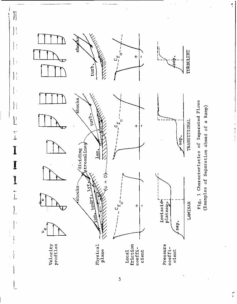
Typical surface pressure distributions are shown in Fig. 1(cf. Refs. 1 through 4). The laminar boundary layer has a char-acteristic plateau where the pressure remains almost constant overmost of the separated flow region. The separation pressure coeffi-cient is based on the pressure rise from the undisturbed stream tothe separati6n pqinit As explicitly mentioned by Love (Ref. 9),this is not to be confused with the pressure rise needed to causeseparation.
4
I1
4-4 1
0 0
L.L.
II II Cl) c
(ii0 ,0H'U 0
$4 C Z
CD H o 4
4-4 1 ~ HuHr Cd .
~ r-4
0*d(nU U H a ca 4-4 4)*r4ý 0r ý> - r . r 1 1 rw .F
P4 44UiL
1 liiL a...5

F I1
The separated turbulent boundary layer pressure distribution hasno plateau region but rises to a peak value (cf. Refs. 1 and 2).The final pressure after reattachment is usually that given by in-viscid theory. occasionallya situation arises *wherein there isa pressure rise above the inviscid value followed by an expansionto the inviscid value.4 This is caused by a lower local entropylevel due to the multiple-shock compression of the inviscid flownear the separation. The multiple-shock compression is a moreefficient process than the single-shock compression, resulting ina higher local total pressure. It has been observed occasionallyin three-dimensional hypersonic separation (see Three-DimensionalEffects), and there is good reason to expect it in other situationsat high Mach numbers where multiple oblique shock compression canexist.
The critical pressure rise coefficient, CPcrit' sometimes re- T
ferred to as the incipient pressure rise coefficient, correspondsto the minimum over-all pressure for which separation will occur(cf. Refs. 1, 4, 69 79 9 and 10). The current indications are thatit is independent of the particular geometry causing the pressurerise (cf. Refs. 8 and 11), although this may not prove to be a com-pletely general rule. As previously discussed, CPcrit is much
greater and is a much weaker function of Reynolds number forturbulent boundary layers (Cpcrit • Re-O.1) than for laminar
(Cpcrit - Re-0o. 2 5 ). Correlations are found, however, in earlier
works (e.g. Refs. 6, 10, and 12) that give a higher degree of de-pendence on Reynolds number, but we consider the above exponentscloser to the truth in light of the latest theories and experiments.
The pressure rise due to separation (plateau in the case oflaminar, peak in the case of turbulett) is of the same order ofmagnitude as the critical pressure rise, and exhibits the sametype of dependence on Mach and Reynolds numbers. In laminar flowthe reattachment pressure rise is roughly the same as that of theplateau, but in turbulent flow it is usually from 1/2 to 1/3 of thepeak pressure rise. Detailed correlation formulas for predicting jthe pressure distribution parameters in various situations aregiven in the later sections.
Two further points should be made concerning the general char-acteristics of laminar and turbulent separations. First, the in-crease in Mach number and large changes in stream-to-wall tempera- -ture ratio, that are characteristic of hypersonic flow problems,
6
greatly affect the probability of finding laminar flow at a givenReynolds number, usually in a favorable fashion. And second, thelarge viscous interaction associated with high Mach number and lowReynolds number will often make it very difficult to determine ex-perimentally or theoretically whether separation has even occurred,let alone the separation location. For those conditions where sep-aration is difficult to detect, the effect of separation on loadsis quite small, but the understanding of the flow and the predictionof heat transfer and flow stability becomes uncertain.
The stability and steadiness of separated flows cannot be pre-dicted with certainty using present information. In general, cavi-ties appear to be the most unstable type of separated geometry.Unsteadiness can result from a hysteresis between laminar and tur-bulent separated-zone conditions if the flow conditions and geome-try are of certain types, e.g. a sharply deflected ramp near the
transition point of a flat plate°, Whether all separated-zone in-stabilities are associated with transition, or whether other mechan-isms participate must be determined by future investigations. Theresonant frequency of a cavity would be one important parameter insuch an investigation. Violent macroscopic flow fluctuations af-fect heat-transfer rates and wall shear forces near the separationand reattachment points because of the Reynolds stress effect.This subject is discussed further in the section on Three-Dimen-sional and Unsteady Flows.
The relationships between heat transfer and separation inlaminar and turbulent flow are poorly understood. Chapman (Ref.13) theoretically estimates a ratio of heat transfer in a laminarseparated zone to that in the attached layer, of 0.56 ( seeHeatTransfer subsection). The experiments of Larson (Ref. 14) sub-"stantiate this estimate. Chapman mentions that turbulent separationregions can have heat-transfer rates as high as six times the equiv-alent rate for the attached layer at low Mach numbers, but this
I ratio decreases greatly with increasing Mach number. The turbu-lent flow measurements of Larson do not show this high ratio atlow Mach numbers, but the theory appears to approach the measure-ments at high Mach numbers. Larson states that the discrepancy isprobably due to the failure of the theory to include the propertemperature - heat transfer relationships for the experiments.L Current work by Chapman and co-workers supports this view. Itappears doubtful whether very large increases in heat transfer willever be found in steady, separated regions. In short, turbulentand transitional separations may lead to heat-transfer rates high-er than the equivalent attached boundary layer, but at high Mach
71~

numbers the ratio appears to be about 0.50 to 0.70, which is notindicated satisfactorily by present theory. Local increases inheat-transfer rate near reattachment are mentioned in Ref. 14,but these were not always found by the other investigators mentionedin Ref. 14.
The converse effect, i.e., the effect of heat-transfer rateon separation characteristics, is also not understood (Refs. 14through 23). Sogin states in his survey report (Ref. 22) thatthere is much disagreement between theory and experiment as regardsthe effects of heat transfer on either laminar or turbulent separ-ated flows. Thus, theoretical results for laminar boundary layers(Refs. 15 through 21) indicate separation should be delayed bycooling; this, however, has not been found experimentally (Refs.14 and 24 through 26). Gadd further states that if the turbulentboundary layer could be treated analytically it should also showseparation delayed by cooling (Refs. 24 and 25), but again, poorexperimental agreement is obtained. The resolution of this un-certainty is very important, as it bears directly on the applica-tion of wind-tunnel data (equilibrium wall) to flight problems(usually cold wall).
Cooling in the separated region will affect the location ofthe transition point greatly. Chapman, et al., at NASA Ames Re-search Center, have unpublished results which show a gradual changefrom completely turbulent to completely laminar flow in the separ-ated cavity on a blunt, axisymmetric shape. This change wasachieved solely by cooling the model. The results of these testsshould be published as a NASA report shortly.
Theoretical Methods
Although many useful methods for predicting boundary layerseparation and separated flow characteristics are available, thereis as yet no theoretical solution of the problem that results ingood quantitative agreement with experimental data. Empiricaldata and the results of semiempirical methods, where they exist,seem to be the only usable design information. The limited scopeof experimental data available, especially for hypersonic problems,and the uncertainties associated with extrapolation can lead tosome serious errors in design calculations. The theoretical pro-blem of a separating boundary layer is so difficult that we may
8

TI
never find a dependable solution without recourse to experimentalinformation. The primary value of present theoretical efforts lies,therefore, in their effect on the treatment and correlation of thosedata which are available in order to properly generalize the infor--mation and accurately determine the limits of applicability.
Theoretical solution to boundary layer flow near separationLI is complicated by several effects which do not enter the study of
attached boundary layer flow. The primary difficulty is associated-_with the adverse pressure gradient along the surface which in the
general case prevents the application of similarity solutions tothe boundary layer equations. More basically, we find that theboundary layer equations are often inadequate to describe the flowwhich occurs near a separation point. This is due to the singularnature of the flow near the separation point and the associated in-
i' crease in importance of terms in the Navier-Stokes equations whichare neglected in the boundary layer equations (e.g., normal pressuregradient and ý2 u/ýx2 ). We also find that the interaction withthe flow outside the boundary layer is different in separated flow,and the external pressure distribution is affected by the behaviorof the separated flow. Although these difficulties are sufficientto have prevented solution to low-speed separation problems thusfar, there are additional complications in hypersonic flow. Thefirst of these is the hypersonic flow characteristic of nonlinear-ity between pressure change and local flow angle, requiring a changein the methods commonly used for supersonic flow calculations; thesecond is the great importance of variations in the transport prop-erties within the separated region which result from the large dif-ferences in temperature. In this regard we must expect an increas-ed importance of the wall temperature condition and the heat trans-
T fer to or from the separated region on the flow characteristics°Finally, the problem of boundary layer transition and its inter-action with the separation phenomena must be considered because ofthe extremely large change in flow characteristics which accompaniestransition in the neighborhood of separated flow0 Attempts at thetheoretical solution of problems of transition and the behavior ofturbulent separated regions are even more primitive than those forlaminar flow, but their importance is not diminished in view of theneed for basic understanding of the phenomena.
We review current theoretical work on high-speed separationin the following discussion. Because the Crocco-Lees mixing theory(Ref. 27) is the springboard for much of the theoretical work pre-sented in the literature on separation, it is pertinent to begin
9

this discussion with a brief introduction to it. Applications of
the Crocco-Lees method to the problem of separation are discussed,followed by a discussion of other theoretical approaches.
Crocco-Lees Method
Basically, the Crocco-Lees method (Ref. 27) is an approximateintegral method which uses correlation techniques. Previous in-tegral methods, such as the Karman-Pohlhausen method (Ref, 1i p.206), relate a single parameter, which describes the shape of thevelocity profile in the boundary layer, to the local external-stream velocity gradient. These methods are inadequate for sep-arated flows. For example, the Karman-Pohlhausen method fails forlarge positive pressure gradients such as those associated withseparation. Thwaites• method (Ref. 28), which correlates boundarylryer profiles and local pressure gradients, yields a Blasius flat-plate profile for zero pressure gradient and so fails in the sep-arated laminar plateau region, Nevertheless, modifications ofthese theories are being sought to make this type of approach ap-plicable to separated boundary layers (cf. Ref. 29).
Crocco and Lees introduced a new boundary-layer parameterwhich is a nondimensional ratio of the mean velocity in the bound-ary layer to the free-stream velocity. This parameterc K, canbe shown to be a function of the boundary-layer thickness, 5,the displacement thickness, 5*V and the momentum thickness, 5"*
as follows:
5 - 5* - *1c=
In terms of this parameter a friction correlation function, a mix-ing-rate correlation function, and a mean-temperature correlationfunction are obtained from known boundary-layer solutions or fromexperiment. In their original paper, Crocco and Lees obtainedthese functions from incompressible Falkner-Skan solutions (Ref.
1, p. 118). More recent works (Ref. 30 and 31) have used other
boundary-layer solutions, or empirical correlations.
These functions are used in the momentum integral equation
and in a second integral equation which is a continuity relation
expressing the rate of mixing of fluid from the external region
10
(isentropic stream) with that of the internal region (boundarylayer or dissipative-flow region). Crocco and Lees consider thatthis mixing process is the fundamental mechanism in the growth ofa boundary layer.
* The correlation functions that are obtained from similaritysolutions of the incompressible boundary layer are related to anentire family of compressible flows through the Stewartson trans-
formation (cf. Ref. 32). Although the arbitrariness in definingthe boundary layer thickness would seem to lead to great uncertain-ties because the value of K is seen to be sensitive to the valueof 5, Gadd and Holder (Ref. 25) and Glick (Ref. 31) show that re-sults of the method are fairly insensitive to any conventional
Schoices of 5. The Crocco-Lees method is limited to the case ofzero heat transfer at the wall, constant stagnation enthalpy, smallflow deflection angles, and the standard boundary layer assumptionI that the static pressure gradient normal to the wall is negligiblewithin the boundary layer. Crocco and Lees apply their method tothe problem of determining base pressure and various other problems
I in their report (Ref 0 27).
Cheng and Bray (Ref. 30), apply the Crocco-Lees method to theseparation produced by the interaction between an incident shockwave and a boundary layer over a flat plate, as suggested by Croccoin Ref. 33. They are unsuccessful in finding suitable correlationfunctions for Qther than laminar flow, and even for laminar flow,the results of the final calculations agree only qualitatively withexperiment. The calculated length of the separation bubble, forexample, is an order of magnitude larger than that observed ex-perimentally.
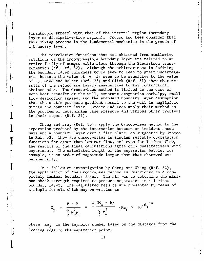
1 In a follow-on investigation by Cheng and Chang (Ref. 34),the application of the Crocco-Lees method is restricted to a com-pletely laminar boundary layer. The aim was to determine the mini-mum shock strength required to produce separation in a laminarboundary layer. The calculated results are presented by means ofa simple formula which may be written as
p- P-p a (M - b) -6 7cC = 2p M (Re x 10
2 oo 2
where Res is the Reynolds number based on the distance from the
Hi leading edge to the separation point.
II

In the case of Cpsep the calculated results show that a 0.03181
b = 0.4, and c = 0.160. In the case of Cpcrit a = 0°060, b = 0.59
and c = 0.186. These formulas would agree with the available ex-perimental data of Ref. 3 if for Cpsep the value of "a" were equal
to 0.040o The same would be true for the data of Ref. 35 if forCpep o were equal to 0.056, and for Cpit a were equal to
0.120. These results indicate good qualitative agreement with ex-periment but unsatisfactory quantitative agreement. The authorsclaim, however, that the quantitative difference is not as greatas the differences among the experimental data insofar as pressureratio is concerned.
Glick, (Ref, 31), uses the theoretical studies of Thwaites,Howarth, Falkner-Skan, and Hartree, (Refs. 28, 36, 1, p. 118, and37) and the experimental study of flow over a.a ellipse by Schubauer(Ref. 38) in an attempt to find relations for the Crocco-Lees cor-relation functions in terms of K, for the flow region up to theseparation point. Beyond the separation point, the correlationfunctions are obtained by means of experimental data. The con-ditions of the experiment selected are M. = 2.45 and RE./inch =
6 x 1o4. The technique is employed in the reattaching region aswell, using data from the same experiment. Glick claims to haveachieved quantitative success with this approach. However, in theregion downstream of separation the correlation functions are ob-tained from experimental conditions that are close to the condi-tions that the calculated results are compared with; c.aution isadvisable here% His calculations are for the case of separationinduced by a shock wave interacting with a laminar boundary layerin a free stream of Mach 2, and a separation Reynolds number of2.3 x 105, He has also completed calculations for a case wherethe Mach number is 5.8 and the separation Reynolds number is1 x 105, but unfortunately no experimental data were available tocheck these results. Glick explains why previous uses of Falkner-Skan solutions to obtain the correlation functions have not result-ed in good correlation with experiment. The basic reason is "thephysical fact that Falkner-Skan flows are similar flows which donot have histories and do not reflect the essential change in shapeof the velocity profile prior to separation."
Based on the results that Glick has had with his modificationof the Crocco-Lees method, he appears to be very optimistic con-cerning its further use. He suggests that more calculations be
12

made with this method for other separated flow geometries such asforward and rearward facing steps, corners, cutouts, ramps, etc.As noted above, Glick maintains that the method is not sensitiveto the definition of the thickness of the boundary layer.
Bray, Gadd, and Woodger (Ref. 39) obtain their relations forthe Crocco-Lees correlation functions from the similarity solutions,of the compressible, laminar boundary layer by Cohen and Reshotko,(Refs. 15 and 16). The relations are derived and presented in termsof the velocity ratio F', and the similarity variable, il. Someof these similarity solutions have negative values of F' at lowvalues of 1, indicating reverse flow near the wall. These arecalled '"lower-branch"' solutions and were first discovered and namedby Stewartson (Ref. 40).
Prior to the approach of Bray, Gadd, and Woodger it was assum-ed that the boundary layer was bounded at its inner edge (in theseparated zone) by a region of relatively motionless flow. The
approach taken in Ref. 39, (or Ref. 25), was to base the relationsfor the Crocco-Lees correlation functions on the lower-branch solu-tions of Cohen and Reshotko in the separated zone, as mentionedabove, and on the upper-branch solutions for the attached regionof flow. This approach is more in keeping with the experimentalobservation of flow reversal near the wall after the separationpoint. Nevertheless, the authors claim that the results of thisapproach agree only qualitatively with experiment. Because ofthis and because of the algebraic complexity of the method, theysuggest the use of a new and simpler method which th~ey present.This new method is a Pohlhausen-type method and does not result inbetter agreement with experiment, although the results are as goodas those of the Crocco-Lees method. An important result of theircalculations, however, is the discovery of the "laminar foot" (cf.Fig. 1, page 5 ) which had not been shown in previous analysesi of separated laminar boundary layers.
Other Methods
Hammitt (Ref. 5), using a simple flow model for turbulentboundary layer separation due to an abrupt increase in pressure(Fig. 2), postulates that within the small shock-wave boundary-layer interaction region the transport of mass and momentum into
13

tb.e boundary layer is small.Also, near separation, shearforces at the wall are neglect-ed in the shock-wave boundary-layer interaction region. Con-servation of mass and momentumare used to connect the up- Mstream and downstream equili- V-2,brium boundary layers adjusted POthrough the small interactionregion where the pressure _ p"
changes are large. Mass and BOUNDARYmomentum transfer from either -the stream or the wall and the low region / Ieffect of skin friction are ne-
glected in this region. A one- Fig. 2 - Simple Flow Model for tparameter boundary layer profile Turbulent Boundary Layer Separa-is used and only average condi- tiontions through the boundary lay-er are considered; a parameteris defined as the ratio of an average velocity to the velocity atthe edge of the boundary layer, the average velocity being taken asthe ratio of the momentum to the mass flow.
Hammitt is one of many who express the opinion that the effectsof compressibility on boundary layers should be of a quantitativerather than a qualitative nature (cf. Refs. 5 and 11). Schuh (Ref.11), Mager (Refs, 41 through 43), and Culick and Hill (Ref. 44) pre-sent transformations used in extending incompressible solutions tocompressible flow cases. Mager obtains an incompressible relation-ship between the velocities immediately upstream and downstream ofseparation, V2
2 = KV2 ,O, and similarly relates the correspondingMach numbers across shock waves for compressible flows Mi = KM. (seeFig. 2). The experimental range of K is between 0.49 and 0.60regardless of the geometric mechanism causing separation. UsingSchuh's empirical results, Mager (Ref. 42) arrives at the follow-ing expressions for the pressure ratios for turbulent separation:
sep + M+ 2 1 - KIM2
14
I

HI and
P'2 _ sep 1l+G]
POO3
where
K M? -1G =-0.328 -
2
andi
1 K = 0.55
Separation and final pressure coefficients, obtained fromthe above empirical theories and experimental correlations, areplotted in Fig. 3 (cf. Refs, 5, 11, 43, and 45). The results all11 agree fairly well with Schuh's experimental correlation.
It is important to remember, however, that a certain amount
of agreement is guaranteed in each case by the use of empiricaldata in evaluating constants and parameters for the differenttheories. This is especially important when we consider their ex-tension to higher Mach numbers. The flow model used in Ref. 5 in-dicates a decrease in the thicknesst:of the turbulent boundary lay-er whereas all other theoretical and experimental evidence indicatesthat the boundary layer will thicken downstream of the'shock-wave
15

boundary-layer interaction re- 0.[gion (see, e.g., Ref. 2, p.472). 0.. Hammit
Bogdonoff and Kepler (Ref.46) study turbulent boundarylayer interaction using a flow 0 - Magermodel which they feel suscepti- \eIble to the type of treatment 0. Nproposed by Crocco and Lees; C Mpeakthey point out, however, that p Schuh
more information on mixing C-rates, particularly in the Psep MIseparated flow region, is need- 0o. 1 Ied for the direct application 0 1 2 5of the Crocco-Lees method. In Ma more recent work, Gadd (Ref. _47) presents a simple new meth- Fig. 3 - Turbulent Separationod for treating the interac- Pressure Coefficientstion of normal shock waves and turbulent boundary layers on flat Isurfaces.
The problem of separation for both turbulent and laminar com-pressible boundary layers is treated by Honda (cf. Refs. 400 and
4ý9). He splits the turbulent boundary layer into an outer, es-sentially inviscid, layer and an adjacent, inner, viscid layer.For the laminar layer prior to the point of separation, Honda usesthe momentum integral equation, the energy integral equation, andthe mixing rate continuity equation. He introduces four parametersafter applying Stewartson's transformation and determines the re-lations between them by using Pohlhausen's fourth degree poly-nomial for the velocity profile. For the laminar separated layer,he assumes a physical model in which the separation streamline re-presents the "wall" of the layer where u = 0. He assumes that theusual boundary layer assumptions still hold in the separated layerand transforms the mass, momentum, and energy flux equations againusing Stewartson's transformation. He then makes two assumptions:that the separation streamline is a straight line, and that theboundary layer profile in the layer is similar to the profile atthe point of separation. The results of this approach upstreamand immediately downstream of the point of separation agree reason-ably well with experiment for M r 2 to 3.
16
IJ
11Semiempirical theories for laminar separation, based on simpler
flow models than that used in the Crocco-Lees method, have been pro-posed by Gadd (Refs. 50 and 51), Chapman (Ref. 3), Donaldson (Ref.
12), and others. Pressure distributions are considered first in
the absence of heat-transfer effects.
The general qualitative shape of the pressure distributioncurve in the region of incipient separation of laminar boundarylayers is presented in an early paper by Gadd (Ref. 50); the actualseparation point cannot be determined because the boundary layeris represented by similar profiles (Refs. 15 and 16) and so theseparation profile is never realized. A more quantitative approachtaken by Gadd (Ref. 51) is to split the boundary layer into two ad-jacent layers: a very thin layer next to the wall and an outerlayer comprising the remainder of the boundary layer. The outerlayer may be calculated using an essentially inviscid analysis.The inner layer is calculated by requiring that the shear and pres-sure gradients balance and that the profile of the inner layersmoothly join that of the outer layer. The line separating thelayers is not necessarily a streamline. Gadd accomplishes this
for the general case and then for the simpler case when the innerlayer may be assumed to be only a minor portion of the total thick-ness of theboundary layer. The differences in the results are al-most nil. In this manner the Cp equation on page 24 is obtained.
A similar procedure, but using several adjacent layers, is current-ly proposed by C. Donaldson of A.R.A.P. *A theoretical treat-ment of moderately separated flows due to a prescribed, continuous,(isentropic) pressure rise is presented by Bloom in Ref. 67. Thevelocity profile is assumed representable by a fourth degree poly-nomial and the integral method, described on pages 206 and 289 of
¶ Ref. 1, is used.
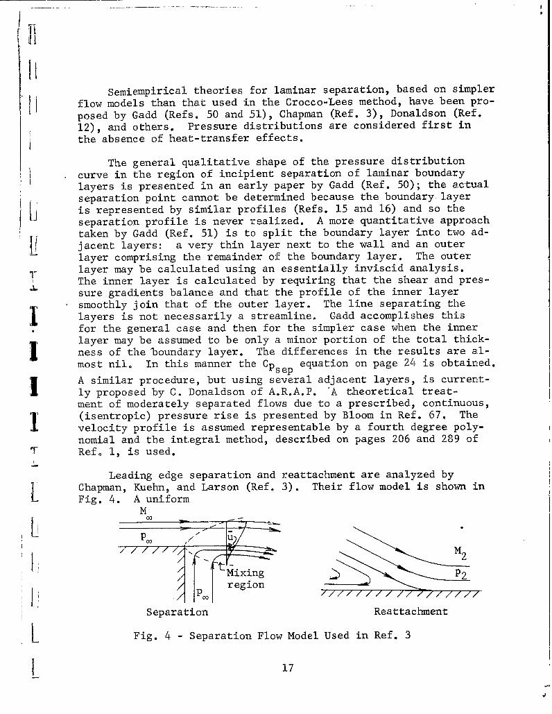
Leading edge separation and reattachment are analyzed byChapman, Kuehn, and Larson (Ref. 3). Their flow model is shown inFig. 4. A uniform
MCO
7-177-77W
Mixing P2region
P2
Separation Reattachment
L Fig. 4 - Separation Flow Model Used in Ref. 3
17

stream with no boundary layer, mixes with a dead air region ofequal pressure. The mixing region grows parabolically, similar tothe growth of laminar boundary layers, and is composed of similarprofiles. Therefore, the velocity ratio U/u•, where U is thevelocity along the dividing streamline, remains constant. TheBlasius equation may then be solved and, for a linear viscosity-'temperature law, it is found that the velocity ratio is constant:U/ u, = 0.587. Furthermore, for Mach numbers less than 5 anda power law relationship between viscosity and temperature, thevalue of U is essentially constant; thus, regardless of Reynoldsnumber, streamwise station, viscosity-temperature law, and Machnumber, u 0.587 as long as the initial velocity is uniform.The dividing streamline at separation, by continuity for steadyflows, must be the dividing streamline at reattachment. The massflow scavenged from the dead air region by the mixing layer mustequal the mass flow reversed back into the dead air region by thepressure rise at separation. Assuming isentropic compression of fthe stream flow at reattachment, Chapman, Kuehn, and Larson (Ref. 3)obtain the expressions
T
1. + - 1 2 y-1_POO= 2 M2
p 12P2 2
1+ i M2
and
2 2(i-2) M2 2 2(1- 2142C for 0. .587 M 2 0.655 M C
where subscript co indicates undisturbed stream conditions and sub-script 2 indicates conditions at the end of the reattachment zone.Thus, the pressure rise across reattachment is given in the first
18
'1

equation and, from the second equation and using u, 0.587, theMach number ratio across reattachment. The second equation is ofthe same form as 'Mager's equation on page 15 but the constant forthe isentropic pressure rise at reattachment is higher.
Heat. Transfer,
Chapman, Gadd, and several others present analyses including
heat-transfer effects (cfo Refs. 13 through 24 and 51). Chapman(Ref. 13) uses the same flow model as shown in Fig. 4 and a com-pressible-flow modification of the von Mises stream function trans-formation (Ref. 1, page 122). The momentum and energy equationsL are solved for the case of constant wall enthalpy for various valuesof the Prandt.l number, and Sutherland's viscosity-temperature law(Ref. 53, page 168). The velocity ratio along the dividing stream-
I line is again found to be constant and equal to 0.587, and varia-tions of Pr were found to affect the results negligibly. Bound-ary-layer theory is again assumed to be valid in the mixing region.
I Chapman's results are only for the over-allheat transfer to theseparated flow region and do not represent a heat-transfer distri-bution. He obtains the results that the average heat-transfer ratefor a separated laminar boundary layer is 56% of the heat-transferrate for an attached laminar boundary layer on a flat plates. Chap-man (Ref. 13) presents the low Mach -number turbulent separated case
Sfor Pr = 1 and obtains the result that the average heat transferin a turbulent separated region may be 6.3 times as great: as thatfor an attached turbulent boundary layer on a flat plate. Consider-L. able doubt exists as to the accuracy of this result, as it is notevident in experiments (see General Characteristics). He also cal-culates the effective skin friction in the separated laminar caseh and finds it to be about six tenths of the attached value. The caseof fluid injection into the dead air region is considered, and itis shown that minor mass injection would greatly reduce the heattransfer to the wall.
Gadd (Ref. 51) states that his theory, as described above, pre-Ii dicts that cooling a wall increases the pressure rise required toseparate a laminar boundary layer. In agreement with Gadd, Poots(Ref. 54) shows that heating a wall encourages separation. Gaddstates that although his results may be qualitatively correct, theyare useless quantitatively and that the unrigorous dimensional argu-
I ments presented by Chapman (Ref. 13) give much better agreement for
L19
L

over-all heat transfer with the experimental work of Larson (Ref.14). Heat transfer effects on separated flow regions were investi-
gated using observations of free flight tests at supersonic (Ref.52) and at hypersonic (Ref. 65) Mach numbers. Lankford presentsexperimental data which demonstrate that laminar separation aheadof axisymmetric compression corners is delayed by reducing the walltemperature. The extent of separation is reduced and the inviscidpressure distribution is approached as the wall temperature is low-ered, whereas heating the wall causes upstream movement of the sep-aration point (Ref. 65).
Experimental evidence obtained by Larson (Ref. 14) and also bySebanP Emery, and Levy (Ref. 55) for separated turbulent boundarylayer flows indicate the failure of theoretical analyses in predict.- Iing the heat-transfer effects. For example, the theory postulatedby Chapman (Ref. 13) described above, does not give reasonable esti-mates for even the over-all, (average) heat transfer, much less thedetailed distribution of heat transfer, to regions for separatedturbulent boundary layers. Further work on heat-transfer effectson separated-zone pressures and transition is currently in progressat NASA, Ames Laboratory. The dearth of papers on theoretical andexperimental research on heat-transfer effects for separated turbu-lent boundary layers is brought out in several survey type reports(cf. Refs. 22 and 56)°
Finally, Kuo (Ref. 23) determined that although dissociationdoes greatly reduce the thermal boundary layer thickness and lowersthe temperature at the outer edge of the boundary layer, the in-clusion of dissociation effects for a gas in dissociated equilib-rium does not affect either the heat flux or'the friction coeffi-cient at the wall for either laminar or turbulent boundary layers.Dissociation effects may be included in boundary layer analyses by 1using Cohen's correlation formulas and tables (Ref, 57).
.1Separation on, Windward Surfaces
The major portion of the forces acting on a hypersonic vehicleare experienced by the compression surfaces, and the understandingof the flow field over such surfaces is of paramount importance.Shock induced separation, due to incident shock waves, forward fac-ing steps, ramps and spikes, is treated here. Except for a singlestudy of separation due to supersonic isentropic compression (a fil •leted ramp), virtually all studies that we describe involve shock-wave boundary-layer interaction.
20
Incident Shock-Wave Separation
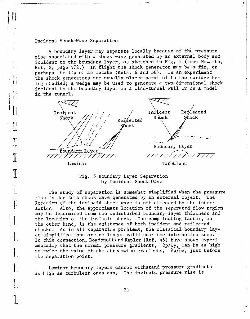
A boundary layer may separate locally because of the pressurerise associated with a shock wave generated by an external body andincident to the boundary layer, as sketched in Fig. 5 (from Howarth,Ref. 2, page 472.) In flight the shock generator may be a fin, or
perhaps the lip of an intake (Refs. 6 and 58). In an experimentthe shock generators are usually plac2d parallel to the surface be-
I ing studied; a wedge may be used to generate a two-dimensional shockincident to the boundary layer on a wind-tunnel wall or on a modelin the tunnel.
[I Incident ///// entdent Re ectedSh k S k c
Ref ected Shcoc/ ock
4/
_ Boundary LayerB oun•ry_ L~y r - -//57"
//777Z//7777 77777
Laminar Turbulent
1 Fig. 5 Boundary Layer Separationby Incident Shock Wave
I The study of separation is somewhat simplified when the pressurerise is due to a shock wave generated by an external object. Thelocation of the inviscid shock wave is not affected by the inter-action. Also, the approximate location of the separated flow regionmay be determined from the undisturbed boundary layer thickness and
[} the location of the inviscid shock. One complicating factor, onthe other hand, is the existence of both incident and reflectedshocks, As in all separation problems, the classical boundary lay-er simplifications are no longer valid near the interaction zone.In this connection, BogdonoffandKepler (Ref. 46) have shown experi-mentally that the normal pressure gradients, ýp/6y, can be as high
L• as twice the value of the streamwise gradients, 6p/ýx, just beforethe separation point.
L Laminar boundary layers cannot withstand pressure gradientsas high as turbulent ones can. The inviscid pressure rise is
21
]
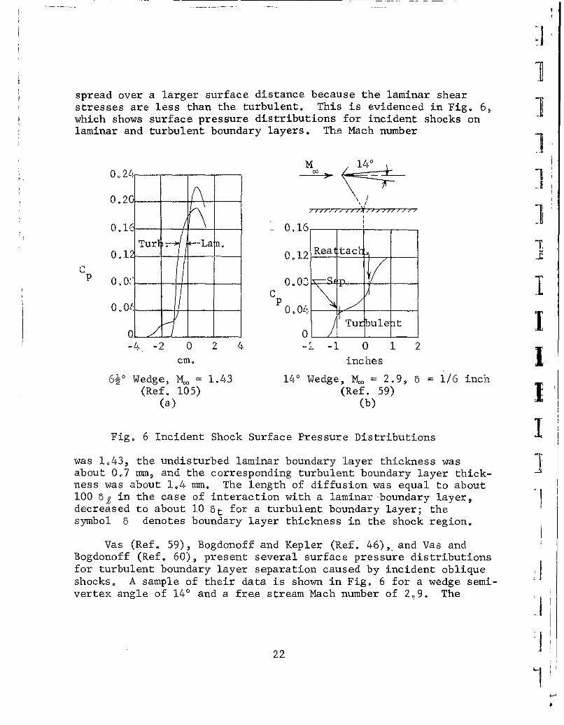
spread over a larger surface distance because the laminar shearstresses are less than the turbulent. This is evidenced in Fig. 6,which shows surface pressure distributions for incident shocks onlaminar and turbulent boundary layers. The Mach number
M 1400,.24 00 >. 1
I I0.20-.
0.1016 16 0,16
Turb 7 <--La tn. 7_012 - 0.12 Rea-ttac[
0 0.0ý-P 0. 04
0 0-0 0 .fuleat I
-4 -2 0 2 4 -1 0 1 2
cm, inches I26 Wedge, Mw = 1.43 14' Wedge, Mc = 2.9, 1/6 inch
(Ref. 105) (Ref. 59)(a) (b)
Fig. 6 Incident Shock Surface Pressure Distributions 1
was 1,43, the undisturbed laminar boundary layer thickness wasabout 0.7 mm, and the corresponding turbulent boundary layer thick-ness was about 1.4 mm. The length of diffusion was equal to about100 5 in the case of interaction with a laminar-boundary layer,decreased to about 10 bt for a turbulent boundary layer; thesymbol 5 denotes boundary, layer thickness in the shock region.
Vas (Ref. 59), Bogdonoff and Kepler (Ref. 46), and Vas andBogdonoff (Ref. 60), present several surface pressure distributionsfor turbulent boundary layer separation caused by incident obliqueshocks. A sample of their data is shown in Fig. 6 for a wedge semi-vertex angle of 140 and a free stream Mach number of 2.9. The
22
points of separation and reattachment are indicated. The separated[I flow region was about (3/4) 5t in height and 61 bt long, where bt.is the thickness of the undisturbed turbulent boundary layer. Vasstates 'that the boundary layer for the case presented in Fig. 6bwas "definitely turbulent". The greater spread of the pressurerise, over that shown in Fig. 6a for a turbulent- boundary layer,is due to the much smaller shock angle and thicker boundary layer.The wedge angle was varied from G to 14 degrees and total pressureprobes, both forward and rearward facing, were used to survey theentire interaction region. The boundary layer did not separate
A for the 30 wedge; for all greater wedge angles the boundary layerdid separate., with the length of the separated flow region increas-ing with wedge angle. The streamwise Mach number distribution,measured 0.01" above the wall, was plotted versus x for all wedgeangles. For the 3" wedge there is a large dip in the curve andseparation is nearly incipient. For the thicker wedges the dipgoes below the M = 0 axis, indicating reverse flow. The plots aresimilar in shape to the local friction plots shown in Fig. 1,y page 5 . The pressure ratio across the 8° wedge shock of Vas, forM = 2.9, is just less than 1.0 (Ref, 61). This pressure ratio isequal to that needed to separate a turbulent boundary layer by a'normal shock wave (Ref. 1). It appears from this that the critical
_ pressure rise is relatively insensitive to the geometry of the in-cident shock wave, but is a function of the strength of the shockwave,
Investigations of pressure rises associated with turbulentboundary layer separation caused by incident shocks (sometimes re-ferred to as reflected-shock separation) are presented in Refs. 3,6, 7, 9, 41, 42, 439 46, 59, and 62. In Fig. 43 of the report byChapman, Kuehn and Larson (Ref. 3), the separation pressure rise forincident shocks is plotted versus Reynolds number for three Machnumbers,, The separation pressure rise for turbulent layers is aweak function of Reynolds number, becoming essentially independentof Reynolds number as the free stream Mach number increases and,in agreement with Schuh (Ref,. 11), as the Reynolds number increases
_ over about 107, As mentioned earlier, Mager (Refs, 41 through 43)
-- obtains separation pressure rises which are independent of geometry;thus, the theoretical relations presented on page 14 are taken to
I hold for incident shocks.
Shock waves incident to laminar boundary layers have been
L studied by Hakkinen etal., Gadd, and Greber (Refs. 13, 35, 51, and63) and are discussed in the works of Lange and Love (Refs. 6 and 9).
23
L
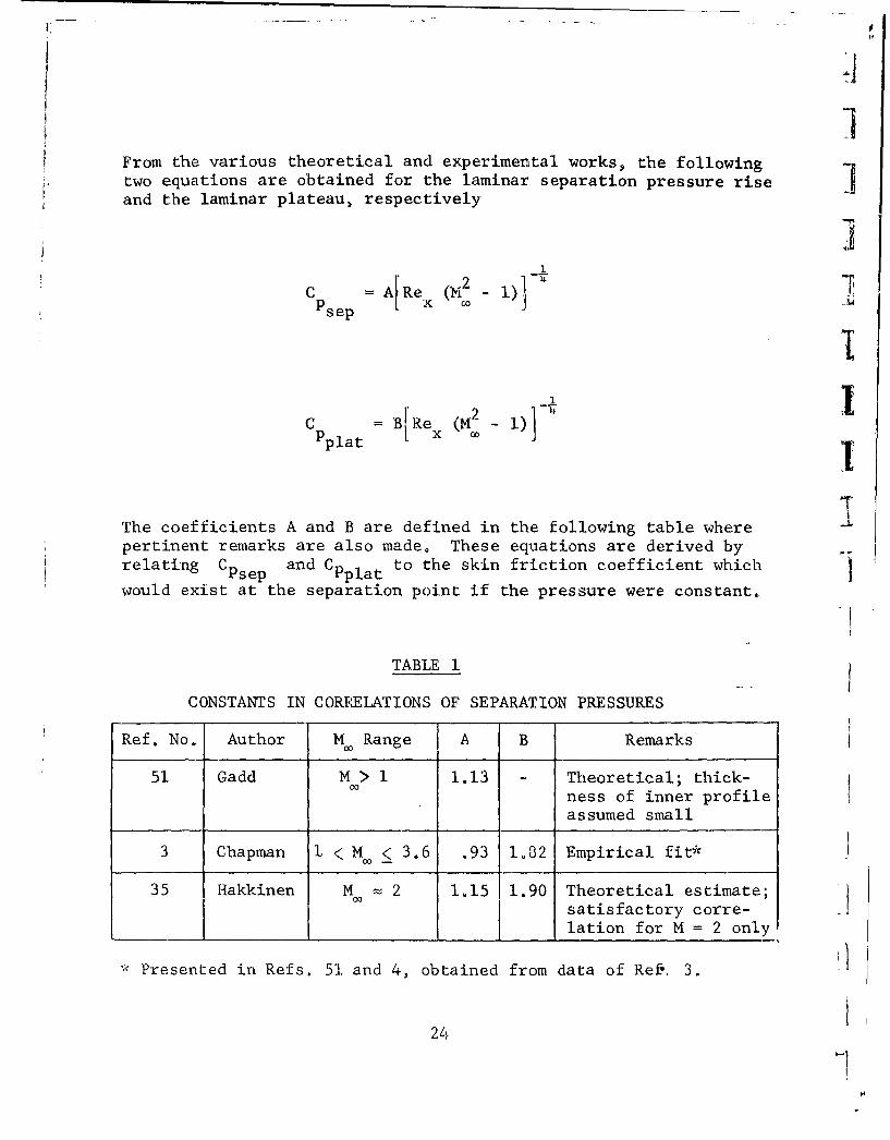
IFrom the various theoretical and experimental works, the followingtwo equations are obtained for the laminar separation pressure riseand the laminar plateau, respectively
4]C A Re (M -1)
Psep 0
I
Pplat 1
The coefficients A and B are defined in the following table wherepertinent remarks are also made. These equations are derived byrelating Cpsep and Cpplat to the skin friction coefficient which
would exist at the separation point if the pressure were constant.
TABLE 1
CONSTANTS IN CORRELATIONS OF SEPARATION PRESSURES
Ref. No. Author M Range A B Remarks
51 Gadd M > 1 1.13 - Theoretical; thick-ness of inner profile
assumed small
3 Chapman 1 < M < 3.6 .93 1.82 Empirical fit*
35 1Iakkinen Mo400 2 1,15 1.90 Theoretical estimate;satisfactory corre-lation for M = 2 only
• Presented in Refs. 51. and 4, obtained from data of Ref. 3.
,124
VI Since present indications are that the laminar separation pres-sure rise and laminar plateau pressure are independent of the typeof shock inducing separation, the above equations hold as well forU other types of laminar separation, As new results are obtained,however, the form of the equations, and the values of the coeffi-cients A and B, may show dependence on geometry as the Mach numberII increases.
Hakkinen, et al., (Ref. 35) derive a relationship for theplateau pressure rise, namely
SC =I•6'5 CPplat Psep
This expression agrees quite well with the data at M = 2; at otherMach numbers its validity has not been verified, They further notethat the boundary layer profiles are modified near the wall in theseparated flow region. Outside of the reverse-flow region theboundary layer behaves much as an undisturbed boundary layer. Up-stream and downstream of separation for the laminar case the skinfriction is close to the Blasius value. If the separated flow re-gion is long enough, the characteristic laminar plateau appears,The pressure rises to the plateau value from its undisturbed valueupstream of separation and then rises to the final pressure down-stream of reattachment; the final pressure corresponds to that be-hind the incident and the reflected shock waves, Their theoreticaltreatment is based on these experimental observations,
Two-dimensional surface curvature effects on the pressure risesassociated with oblique shock waves incident to laminar boundarylayers are presented by Greber and Gadd (Refs. 18, 51,and 63). Ex-1perimental results indicate that the curvature effects can merelybe superimposed on the flat plate interaction results. Curvaturlleads to a favorable pressure gradient flow which is calculableusing Prandtl-Meyer expansion- Thus, the strength of the incidentshock causing incipient separation must be increased to account forthe Prandtl-Meyer decrease in pressure, the critical pressure co-efficient remaining unchanged.So also, for separated boundary lay-ers, the pressure in the separated region. the plateau pressure,is reduced on the curved wall by the inviscid pressure decreaseassociated with the curvature,
The boundary layer may be laminar at separation and be-
come turbulent before reattachment; separation of this transitional
L
iii
type of boundary layer 'by incident shock waves exhibits the generalcharacteristics discussed earlier, The laminar plateau region is 7shortened, and downstream of transition the pressure distributionis similar to that for turbulent boundary layers (cf, Fig,, 1 ofthis report, Fig, 16 of Ref, 3). Ha.kkinen's (Ref, 35) results in.-dicate a large increase in skin friction for turbulent reattach-ment; also, the pressure usually rises above its inviscid valueand must decay back down to it whereas, for laminar rea•ttachment'[the pressure rises monotonically to its inviscid value.
Boundary layer separation. is to be expected ahead of forward- ]
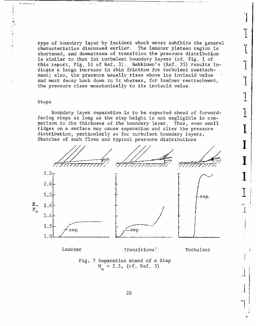
facing steps as long as the step height is not negligible in com-parison to the thickness of the boundary layer, Thus, even smallridges on a surface may cause separation and alter the pressuredistribution, particularly so for turbulent boundary ]ayers,Sketches of such flows and typical pressure distributions
X/
.- '/7777•,/:77. .-7 7 /17777727;,777/ 7/-7-7./•
2,2, -' II
2.0o
1c-sep.
P-- I o
-2-Zs ep, s s~ep.
Laminar transitional Turbulent
Fig. 7 Separation ahead of a StepM = 2,3, (cf., Ref. 3)
26 1
are shown in Fig. 7 (cf. Refs. 3, 4, and 46). Separation aheadof a step is a strong, self-induced interaction flow, The invis-cid flow affects the viscid flow and is in return affected by theviscid flow. Thus the separation point is not known beforehand;
~ the flow adjusts itself to an equilibrium position. The reattach-ment point, on the other hand, must be at the top of the step.
A laminar boundary layer cannot withstand the pressure risethat a turbulent one can, and so separates much further upstream.The effective shape seen by the inviscid flow is a wedge of smallslope, as evidenced by the shock wave pattern and by the surfacepressure distribution. Turbulent boundary layers separate justahead of the step and give rise to much stronger shock waves.
As an example, Sterrett and Emery (Ref. 4) state that for iden-tical steps and free stream Mach numbers laminar separation occurredabout 17 step heights upstream of the 4 step whereas turbulentseparation occurred about 4 step heights upstream and had a pres-sure rise 3 times as great as the laminar pressure rise. Onceagain transitional separation yields a flow picture and pressuredistribution which are composites of the laminar and turbulentcases; the length of the separated flow region is between the lam-
I inar and turbulent lengths and the pressure distribution resemblesthe laminar case. The characteristic plateau prevails up to thetransition point, after which the flow resembles the turbulentcase, The total pressure rise is between those associated withlaminar and turbulent separations,
The turbulent pressure distribution has a characteristic peakprior to reattachment. The peak pressure ratio increases and moves
ii upstream as the step height increases (Refs. 6 and 46). The valueL of the peak pressure rise coefficient is apparently independent of
Reynolds number, as evidenced in Fig. 16 of Ref. 4, Fig. 5 of Ref.b 69 Fig. 6 of Ref. 9, Fig. 20 of Ref., 46, and Fig. 1 of Ref. 64,
The peak pressure rise coefficient for turbulent separationahead of steps decreases with increasing Mach number. Reshotko andTucker present their analysis of turbulent separation ahead ofsteps in Ref. 7; they find that the pressure rise ratios should befunctions of the Mach number ratio across the inviscid shock wave,For the peak pressure rise ratio the Mach number ratio is 0.762.Their prediction is fairly good for undisturbed stream Mach numbersL less than about 3½. Mager's work, which involves a Mach number
27
1.

ratio also, does not depend on geometry and is shown on page 16;for this case the ratio varies from, 0,7 to 0.775, Lange's earlierempirical work leads to Cea = 0,524009M. which is in fairly•peak CO
good agreement with the later results of Refs, 4, 7, and 9 for 1.5< M 3.5, The following empirical relationships of Love (Ref,1009) and St:nrett .id Emery (Ref, 4) adequately predict the peak pres-sure rise coefficient, which is seen to be independent of the Machnumber ratio across the shock;
from Love, for 1i5 < M < 3ý5, and H > 6
IC = 3,2
Ppeak 2± (M -. 1
and from Sterrett and Emery, for 3.5 < M < 6.5, and H > 5
T
C 0,13 - IS5 + 9,1Ppeak M 2 M 3
iiSterrett and Emery mention the important fact that the above equa-tions are only applicable once the step height is sufficientlylarge to give constant peak pressure coefficients, From the ear-lier work of Bogdonoff and Kepler (Ref. 46), we conclude that thestep height must be larger than the undisturbed boundary layerthickness for the equations to hold.
The separation pressure rise does not depend on the height ofthe step (cf. Fig. 7 of Ref. 46). Mager's work leads to a Machnumber ratio of 0.742 for turbulent separation regardless of thegeometry and mechanism causing it (see pages 14 and 15)., Becauseof the steepness of the pressure gradient near separation, it is
230
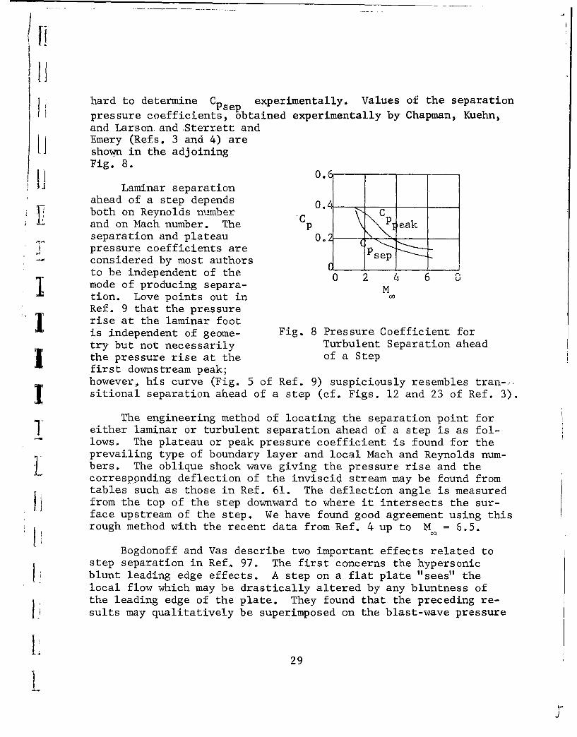
hard to determine C Psep experimentally, Values of the separationpressure coefficients, obtained experimentally by Chapman, Kuehn,and Larson. and .Sterrett andEmery (Refs. 3 and 4) areshown in the adjoiningFig. 8.
0ILaminar separation
ahead of a step depends 0.4_.....both on Reynolds namber Cand on Mach number. The p eakseparation and plateau 0.pressure coefficients are j [pSconsidered by most authors sep
to be independent of the 2 4 6
mode of producing separa- M
tion. Love points out inRef. 9 that the pressureI rise at the laminar footis independent of geome- Fig. 8 Pressure Coefficient fortry but not necessarily Turbulent Separation ahead
the pressure rise at the of a Step
first downstream peak;however,, his curve (Fig. 5 of Ref. 9) suspiciously resembles tran-..-1sitional separation ahead of a step (cf. Figs, 12 and 23 of Ref. 3).
The engineering method of locating the separation point forI either laminar or turbulent separation ahead of a step is as fol-
lows. The plateau or peak pressure coefficient is found for theprevailing type of boundary layer and local Mach and Reynolds num-Lbers, The oblique shock wave giving the pressure rise and thecorresponding deflection of the inviscid stream may be found fromtables such as those in Ref. 61. The deflection angle is measuredfrom the top of the step downward to where it intersects the sur-face upstream of the step. We have found good agreement using thisrough method with the recent data from Ref. 4 up to M = 6.5.
Bogdonoff and Vas describe two important effects related tostep separation in Ref. 97. The first concerns the hypersonicblunt leading edge effects. A step on a flat plate "sees" thelocal flow which may be drastically altered by any bluntness ofthe leading edge of the plate. They found that the preceding re-sults may qualitatively be superimposed on the blast-wave pressure
29
*1o

distribution that would exist over the plate alone in a hypersonicstream. Secondly, they rounded the step making the step front aa hemi-cylinder. The step shoulder was thereby moved downstreamand the pressure in the separated-flow region was reduced,. Thereduction of the pressure is roughly equivalent to the reductionin the blast wave pressure due to the movement of the shoulderdownstreamV and so no reliable results may be drawn for the effectsof rounding the step corner because of the preponderance of theblast wave effect, More discussion of the effects of rounding astep corner is contained in the section on Cavities.
Ramps
Understanding the flow field ahead of a ramp is important forconventional flap-type controls. Again, the geometric effects aremore pronounced for turbulent layers, with the difference betweenthe peak pressures for steps and wedges becoming greater as theMach number increases. Also, the location of boundary layer tran-sition with respect to the separation and reattachment points sig-
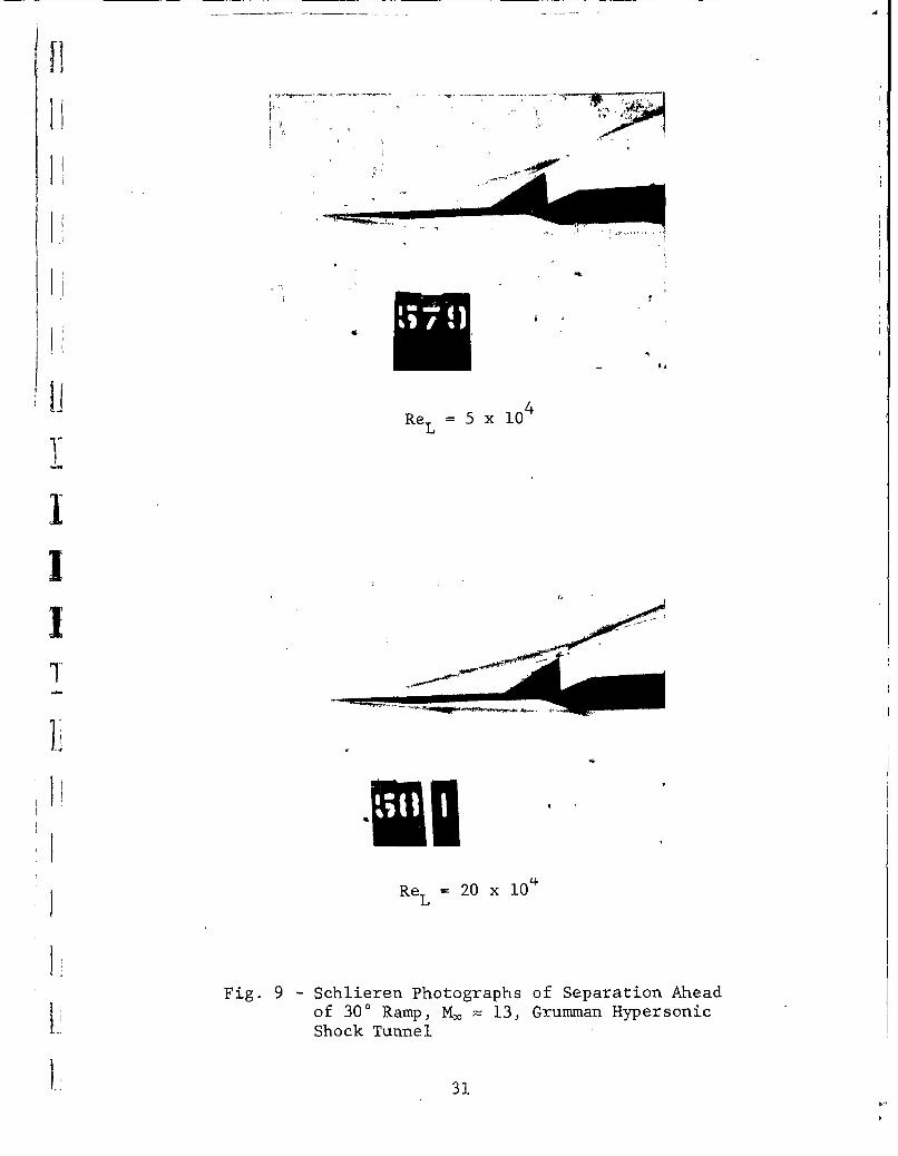
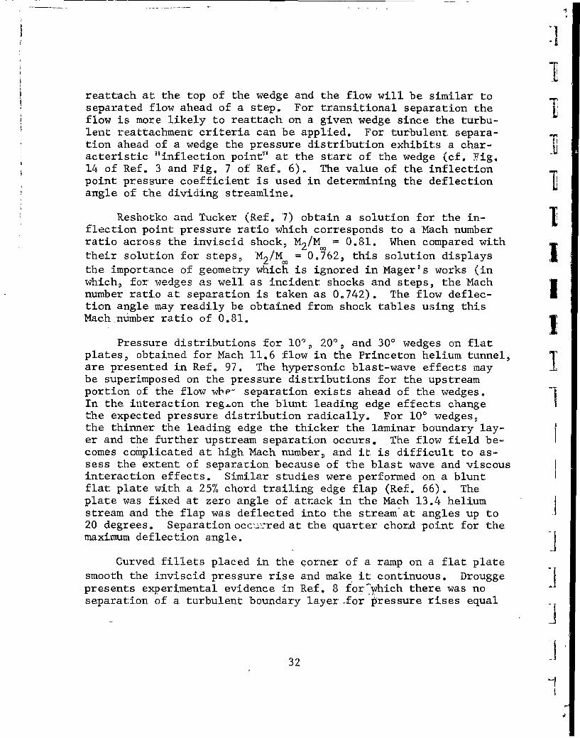
nificantly affects the pressure distribution (Fig. 1). Schlierenphotographs of flow in the Grumman Hypersonic Shock Tunnel infront of a 30' wedge mounted on a 5 inch-long flat plate are shownin Fig. 9 for Mach 13 for Reynolds numbers of 5 x 10⁴ and 20 x 104.Note how the rapid growth of the hypersonic boundary layer makesit very difficult to define a separation point, even when opticaltechniques are used.,
Separated flows in front of ramps are complicated by the fact fthat neither the separation nor the reattachment points are knownbeforehand, The interaction between the shock wave and the bound-ary layer adjusts until an equilibrium position is obtained, Anestimation of the extent of the separated-flow region may be madeas follows., The plateau pressure for laminar separation is asso-ciated with a given oblique shock strength and is also a functionof the Reynolds number at the point of separation. The flow de-flection angle is uniquely determined knowing Mo and P21/ forthe oblique shock (cf. Ref. 61). The flow angle and the corre-sponding flow conditions prior to reattachment may be used to de-termine if the flow will reattach on the ramp. A few iterationsmay be required to obtain a spread of possible solutions or to as-certain if any solution is compatible for the given flow. If thewedge angle is too high, or the wedge is too short, the flow will
30 fV.,
|i
*wJ
ReL11x1 4V L
IT
1:
Fig. 9 - Schlieren Photographs of Separation Ahead1~ of 300 Ramp, M4 i 13, Grumman Hypersonic
1) Shock Tunnel
31.
reattach at the top of the wedge and the flow will be similar toseparated flow ahead of a step. For transitional separation theflow is more likely to reattach on a. given wedge since the turbu-lent reattachment criteria can be applied. For turbulent separa-tion ahead of a wedge the pressure distribution exhibits a char-acteristic "inflection point"' at the start of the wedge (cf. Fig.14 of Ref. 3 and Fig. 7 of Ref. 6), The value of the inflectionpoint pressure coefficient is used in determining the deflection Iangle of the dividing streamline.
Reshotko and Tucker (Ref. 7) obtain a solution for the in-flection point pressure ratio which corresponds to a Mach numberratio across the inviscid shock, M2 /M. = 0.81. When compared with
their solution for steps, M2/M = 0.762, this solution displaysthe importance of geometry which is ignored in Mager's works (inwhich, for wedges as well as incident shocks and steps, the Machnumber ratio at separation is taken as 0.742). The flow deflec- Ition angle may readily be obtained from shock tables using thisMach number ratio of 0.81. 1
Pressure distributions for 10', 200, and 300 wedges on flatplates, obtained for Mach 11.6 flow in the Princeton helium tunnel,are presented in Ref. 97. The hypersonic blast-wave effects may Ibe superimposed on the pressure distributions for the upstreamportion of the flow wbe" separation exists ahead of the wedges.In the interaction reg.on the blunt leading edge effects changethe expected pressure distribution radically. For 10' wedges,the thinner the leading edge the thicker the laminar boundary lay-er and the further upstream separation occurs. The flow field be-comes complicated at high Mach number, and it is difficult to as-sess the extent of separation because of the blast wave and viscousinteraction effects. Similar studies were performed on a bluntflat plate with a 25% chord trailing edge flap (Ref. 66). Theplate was fixed at zero angle of attack in the Mach 13.4 heliumstream and the flap was deflected into the stream at angles up to20 degrees. Separation occx,.:red at the quarter chord point for themaximum deflection angle.
Curved fillets placed in the corner of a ramp on a flat platesmooth the inviscid pressure rise and make it continuous. Drouggepresents experimental evidence in Ref. 8 for"which there was noseparation of a turbulent boundary layer for pressure rises equal
32

to 0.48q for stream Mach numbers of 1.81 and 2.76. AlthoughSchuh mentions in Ref. 11 that these pressure rises, being largerthan the critical pressure rise, cannot be attributed to the con-tinuous compressionj the other authors generally disagree. Typicalpressure distributions ahead of a circularly filleted 250 ramp areshown in Fig. 17 of Ref. 3. No separation at all was observed inthe turbulent case when the ramp was sufficiently filleted.
A theoretical treatment of moderately separated flows due toa prescribed, continuous, (isentropic) pressure rise is presentedby Bloom in Ref. 67. The velocity profile is assumed representableby a fourth degree polynomial and the integral method described onpages 206 and 289 of Ref. 1 is used.
Spikes
Laminar separation may advantageously be used in hypersonicflows, although the use of separation devices, such as spikes,could produce unpredictable forces. The use of spikes in front ofblunt axisymmetric bodies to reduce the forebody drag by effective-ly streamlining the blunt body has been a controversial subjectfor several years. In the endeavor to better understanding thepertinent phenomena, Bogdonoff and Vas present in Ref. 65 an ini-tial experimental study of two-dimensional spikes in front of hemi-cylindrical leading edge flat plates. The basic flow phenomenaare akin to those ahead of a step although the purely separationflow aspects are somewhat clouded over by the use of small models,necessitated by the Princeton Helium Tunnel, and the importance ofth~e hypersonic blunt leading-edge effects.
L t The defining feature of the spiked bodies is the ratio Ra, ofthe length of the thin spike to the thickness of the blunt body(the diameter of the hemicylinder in these cases). Laminar separa-tion near the tip of the spike is observed for Ra < 3. At great-er values of Ra the separation point is on the surface of thespike but little further change in the pressure distribution overthe hemicylinder occurs. The forebody pressure drag is reduced toa very small fraction of that without a spike. In addition to thedrag being only a minor portion of the unspiked body (about 10%),the heat transfer to the hemicylinder was reduced to about 30% ofthe unspiked value. The important requirement for the reductionof the heat-transfer rate is that the boundary layer remain laminar
33
after separation, Finally, deflecting the spike leads to an ef-fective control device. A larger discussion on spikes is foundunder Axisymmetric Bodies.
Separation on Leeward Surfaces IIn subsonic aircraft, the sudden loss of lift, or stall, is.
due to separation on the leeward side of the Uing. At hypersonicspeeds, however, the leeward side of the vehicle contributes onlya minor portion of the lift, so the changes kn flow field due toseparation on the leeward surface do not i .sult in large changesin aerodynamic loads, We consider these pioblems because of theirimportance to heat-transfer distributions and the loss of control Ieffectiveness in regions of detached flow.
This section deals with so-called breakaway separation for Iwhich the flow separates from the surface even though the inviscidstreamwise pressure gradient is favorable, This phenomenon may berelated to the limiting turning angle given by inviscid supersonic Itheory, but the presence of a thick boundary layer often compli-cates prediciton of the flow. Surface geometry often dictates theexistence of breakaway separation, such as from the leading edgeof a sharp plate at high angle of attack or from a rearward-facingstep or base region. The total separated-flow region with reat- -1tachment either in the wake or on the surface must usually be con-sidered in these problems. As in the preceding section, only two-dimensional flows are considered,,
There are two factors which contribute to a flow "breakingaway" from a surface on which, in the inviscid sense, the stream-wise pressure gradient is favorable. High Mach number flows haverelatively small maximum turning angles in a Prandtl-Meyer ex-pansion (e.g. 28' for M = 10, y = 1.4), which result in a predictedcavitation region for surface deflections greater than the maximumangle, This simple phenomenon becomes much more difficult to pre-dict when entropy layers from upstream shock detachment and thickboundary layers create a region of low Mach number flow near thecorner, The inviscid cavitation region now becomes a separated
region, fed by the low-energy fluid near the wall. Equally im-portant is upstream propagation of the effects of downstream re-
compression of the flow, sometimes in the wake, but often on the
body itself. These two factors are often present simultaneously,
and are therefore difficult to isolate conceptually.
34

Fl
The flow sketched in Fig. Sho10 is to be studied under thepresent contract. Intuitively,the inertia of the flow cancause local separation at thesharp ridge; reattachment is Bndry. Lyr.expected upstream of the baseof the test configuration. M SeparatedLessen and Lees (Refs. 68 and flow region69) note that the centrifugalforce acting on the flow mustbe balanced by the radial pres-sure gradient and, using stand-ard boundary layer theory, showthat even highly cooled bound-ary layers (for which the massflow is a maximum near the sm- Fig. 10 Breakaway Separationface rather than near the edge)are always stabilized by convex surface curvature. Interactionsof turbulent boundary layers with Prandtl-Meyer expansion fanshave been investigated in particular by Murthy and Hammitt (Ref.70). The failure of present theory to explain the experimentallyobserved regions of locally separated flows is believed to resultfrom the standard assumption that the boundary layer is thin withrespect to the surface radius of curvature; for sharp edges, suchas the ones under consideration, the surface radius of curvaturevanishes. The complete Navier-Stokes equations must be re-examin-ed for treatment of this problem. A better understanding of the
Li phenomena will facilitate analyzing the general problem where bothsurface curvature and downstream adverse pressure gradient are im-
f portant in causing separation.
Leading-edge separation and reattachment on a concave sur-V I face are treated by Chapman, Kuehn, and Larson (Ref. 3). Their
work is described in Theoretical Approaches. The pressure ratiogiven by their equation on page 13 was found to be independent ofReynolds number and is in excellent agreement with the experimentaldata. In applying the method to flows over rearward-facing steps(sketched with pressure distributions in Fig. 11), small errors
were to be expected in the results because of the existence of a
boundary layer at separation (they assume no initial boundary lay-
er, see page 18). When the transition point was near or upstream
of reattachment shocks were noticeable at recompression and the
35

S~I
1. 01
oo I
Laminar Transitional TurbulentFig. 11 Flows over Rearward Facing Steps (from Ref. 3)
pressure in the separated region decreased. The separated zonewas shortest for turbulent separation and the pressure was only Ia small part of the laminar separation pressure.
The application of the theory of Chapman, et a'., involves Ian iterative scheme, Beheim describes the scheme in Ref. 71 asfollows: first the base pressure is estimated, next the turningangle and Mach number are calculated according to Prandtl-Meyerexpansion, and then isentropic compression at reattachment givesthe final Mach number and pressure, which must agree with theChapman reattachment equation presented on page 13. Beheim in-cludes the use of tabulated values of the velocity ratio alongthe dividing streamline for both laminar and turbulent flows andallows the reattachment surface to be canted up at an arbitraryangle. This method should probably be modified for entropy risein the recompression when the mixing layer is turbulent.
The importance of the ability of boundary layers to transmitthe effects of a pressure rise far upstream is brought out inseveral reports (cf. Refs. 42, 72,and 73). Love (Ref. 72) assumesthe flow behind a blunt-based two-dimensional body to be complete-ly analogous to the flow ahead of a forward facing step, and ob-tains fair experimental agreement for base pressures for turbulent
36
I
boundary layers. The turning angle into the wake behind the bluntI) body is taken to be the angle corresponding to the peak pressure
rise coefficient for turbulent boundary layer separation ahead ofa step which is a function of only the free stream Mach number
Ii (see the equations on page 28). Evident in the flow photographspresented in Ref. 72 is the existence of a "lip shock" immediatelydownstream of the expansion fan at the corner of the base. Appar-ently the flow overexpands slightly and must undergo a compressionthrough a shock wave.
Separation from a smooth surface upstream of the wake is ex-
perienced on many lifting surfaces. As the angle of attack in-creases the critical pressure ratio is exceeded (the trailing-edge shock becomes stronger) and the flow separates before thetrailing edge. The extent of the separation increases with thestrength of the trailing-edge shock that would be required to turn
I the flow parallel to the stream. This form of separation, studied,for example, by Ferrari (Ref. 73), is quite similar to separationin over-expanded nozzles (Refs. 42 and 74). If the ambient dis-
I charge pressure is larger than the critical pressure, separationwill occur in the nozzle. The location of the separation willadjust itself to the point where, for the local value of the Machnumber in the nozzle flow and the character of the boundary layerprevailing at that point (laminar or turbulent), the correspondingseparation pressure-Mach number relationship is satisfied.
Three-Dimensional and Unsteady FlowsYL The preceding sections are limited to descriptions of separa-
tion phenomena which are two-dimensional in nature; this section1, comprises a discussion of three-dimensional and unsteady flowL phenomena associated with separation. Three-dimensional flows
have been observed occasionally over two-dimensional forward andrearward facing steps (Refs. 4 and 75). Sterret and Emery notethat the flow ahead of a step has a three-dimensional characterwhenever transition is close to the point of separation (Ref. 4);the same type of flow is observed by Chapman, Kuehn, and Larsonfor lower stream Mach numbers (Ref. 3, Fig. 35). In the lattercase it is noted that the peak pressure rise measured is consider-ably less than the theoretical two-dimensional value. Kline (Ref.76) suggests that the inception of stall in turbulent boundarylayers cannot be described by any two dimensional flow model.Separation, according to his thesis, comes about through the non-steady appearance of stall in a sublayer produced by an adversepressure gradient. This would mean that turbulent boundary layer
L 37
separdLions can be microscopically three-dimensional even if thesurrounding geometry is two,-dimensional. Unsteadiness of a com-parable magnitude must accompany this effect.
Although the detailed physical process of separation is pro-bably three-dimensional, even for essentially two-dimensional ]boundary conditions, two,-dimensional flow models are amenable toanalysis and the methods described in the preceding sections en-able one to predict roughly the separation flow phenomena on manypractical geometries. Even truly three-dimensional flows, such asseparation ahead of a swept step, may be analyzed by consideringthe component of the flow normal to the step. Macroscopicallythree-dimensional separation and effects of flow fluctuations aredescribed in this section. Particular threedimensional and un- |steady flow effects pertinent to cavities are described in the
following section Flow Over Cavities.
In view of the general lack of solutions to three-dimensionalboundary layer problems, it is even more difficult to give speci-fic information about three-dimensional separation than itt is infthe two-.dimensional case. There are, however, certain specialcharacteristics of three-dimensional separation problems whichshould be discussed. (Three.-dimensional here implies axially non.-symmetric.)
First, the problem of the definition of separation is morecomplex than before. Several authors (cf. Sears, Ref. 77 andMoore, Ref . 73, page 202) have discussed various approaches todefining these separation phenomena. We feel that the best defini- Ition for a specific problem must be the one which deals with the Vflow variables of importance to that problem. One basic criterionwhich Ls often useful is the existence of a dividing stream sur.-face (either closed or, open to the wake) across which there is -no
net macroscopic mass flow. Another, definition uses the locus of I
point:s of vanishing wall shear stres-. Although both of theseideas are useful for certain problems, each can be misleading whenapplied to other, problems of practical importance.
Secondly, we must expect the increased geometric flexibility
of three-,dimensional flows to cause novel behavior of the flow.For example, the requirement of zero velocity everywhere on a sur.-face leads directly to the fact that wall shear stress must alwaysvanish at perpendicular and acute intersections of plane walls, I
38

fit
and this leads to the immediate onset of separation in the pres-ence of adverse pressure gradient. Here we also see the latter
of the suggested definitions failing, as it indicates that astreamwise corner boundary layer is always separated even in afavorable pressure gradient (Ref. 79). It is also possible inmany three-dimensional flows for one flow component to separatewhile the other remains attached. This can lead to large increasesin separation-zone pressure and heat-transfer rate because thechanges in effective body shape and convection in the boundarylayer affect a more energetic flow.
The three-dimensional separation problems most important tocontrol effectiveness are those of "swept" oblique shock inter-action, venting of the low-energy separated flow at the spanwiseextremity of a two-dimensional separation, separation in the pres-I ence of crossflow, and separations along intersection lines. Ofthese, the first appears to be amenable to approximate solutionusing a simple analogy to two-dimensional shock-induced separationin shock coordinates. Theoretical and experimental research onthis problem is being conducted under the present contract. An
indication of the importance of this type of separation can begained from investigation of Fig. 12; the pressures on a flat-plate 65* delta wing are greatly altered by separation inducedby the shock from an underslung cone body. The data shown aretypical of the results of tests performed at Mach 5.1 and 3.1 inAEDC tunnels A and B [AF Contract AF 33(616)-6400, Ref. 80].
The simplest approach to three-dimensional flows ahead of
steps is to consider only the component of the flow normal to thestep. Stalker does this for turbulent boundary layer separation(Refs. 81 and 82). The spanwise component of the flow affectsneither the reattachment line position nor the peak pressure risefor sweepback angles less than about 45 degrees. So also, thepressure rise at reattachment is not influenced by the spanwisecomponent of the flow; the reattachment line is parallel to therearward facing step. The effects of sweepback on shocks incidentto turbulent boundary layers are similarly considered by Gadd(Ref. 47).
In many problems of practical importance spanwise flow intoor out of a separated region has very large influence on the flowcharacteristics in the entire separated region. The shape of a
two-dimensional separation zone is in a large part dependent on
L39L

]0.12
A x 3.0"
0 x -6.5"
0.10 0 x-11. 5
0.081 0 _!0__
C p Cone-Wing Intersection
0.06-- Inviscid Theory
]0.04 1
0 0 G
0.02
000
S0 i I I I I>
0 0.4 0.5 0.6 0.7 0.8 0.9S~S
Fig. 12 - Pressure Distribution near Wing-Body Intersection atHypersonic Speeds (Flat-Plate, 650 Sharp-edged Delta Wing,12.5' Half-cone Body, M• = 8.1, a- 0, ReL - 3.3 x 10⁶ -I
(Data from Ref. 80)).1
40
*1

[1
trapping of the fluid within the envelope of the dividing stream-line. The low-momentum fluid in the separated zone responds read-ily to any lateral pressure gradients which exist, and large changesin separation pressure distributions can thereby result, becausethe effective body shape is altered. We know of no available meth-ods for estimating the magnitude of this effect, but it is beinginvestigated theoretically and experimentally under the presentcontract. The obvious importance of chord-to-span ratio of theseparated region must be considered, with a possible dependenceon the average height of the separation zone as well.
Separation in the presence of crossflow is an unsolved pro-blem for both laminar and turbulent flow, but it does appear like-ly that in certain situations the crossflow effects can be de-coupled from the main-flow component. Citing the above examplesof the swept oblique shocks, one can consider these examples ofpseudo-two-dimensional separations with very strong crossflow.This case shows little effect of the flow parallel to the shock,
'probably because the flow parameters change slowly along theshock. Because of this, the coupling between the two componentsof the vector equation of motion parallel to the surface is veryweak, and the two-dimensional separation phenomena can be con-sidered separately from those of the streamwise flow. All velo-city components must be considered for the energy equation, but
3 •this is straightforward if one is willing to accept reasonableapproximations. Similar decoupling of the flow components shouldbe possible in other problems of separation with crossflow. Sum-maries of recent methods of treating three-dimensional boundarylayers by decoupling crosaflow equations are presented in Refs.83 and 84.
Ii Flow along a streamwise intersection is extremely susceptibleto separation, as mentioned previously. Although shock inter-actions will often predominate over corner boundary layer effectsin hypersonic problems, it is important to understand the phenomenainvolved. Bloom and Rubin give a good summary of the subject (Ref.85). Incompressible experiments, presented in Ref. 79, help togive an understanding of corner separation under adverse pressuregradients. Some questions concerning the development of a momen-tum integral theory for the case of a nonuniform free stream flowhave still not been answered. These points are discussed in Ref.79, and probably apply as well to the high-speed case.
41
L
Another three-dimensional separation problem which shouldbe mentioned is the case of an external corner or edge such asa truncated wingtip. Inviscid phenomena usually predominate insuch flows, but as far as the viscous contributions are concerned,these boundary layers show an increased resistance to separation. IThis is in accord with the decreased separation resistance of in-ternal corners. Some recent work by Stewartson and Howarth (Ref.86) has contributed to the understanding of these flows for zerostreamwise pressure gradient. An important result is that thetransverse momentum exchanges are important even to flows parallelto an edge, and the problem solution must therefore consider insome way all of the components of the vector equations of motion.This result also holds for the internal corner problem. I
Heat-transfer rates and wall shear forces are greatly alterednear separation and reattachment points by macroscopic flow fluc- Ituations because of the Reynolds stress effect. An order of mag-nitude estimate (due to C. Donaldson) of these increases can beobtained in the following way. The average Reynolds stress canbe written as T0 - p Ur"' and the incremental pressure change
due to the flow fluctuation, obtained from supersonic lineartheory, is AO - pp2 Combining these equations with the II
momentum equation, the Reynolds stress becomes T' - (Ap)2=/ --•. "PU2
Correlation of experimental and theoretical data indicates thatthe pressure differential at the separation point can be writtenas (AP)sep - npu2 C, where n is an empirical correlation
(M2 -_1)
constant, n .66 for laminar and .05 for turbulent flow. Theskin friction coefficient due to the Reynolds stress can then bewritten as Cf' - Cf n2 . An estimate of the aerodynamic heating
rate can be obtained if we assume an enthalpy distribution of theform
w Uw w aw
42-4
U
LI
The aerodynamic heating rate can be written as w
1 "L� k�W�{ (U). Applying this equation to the steady and
unsteady terms, and assuming a constant Prandtl number, we obtain
__w = _w_ f W n. This relationship enables us to estimatew 7w Cfo
the increase in heating due to oscillations when the equivalentheating rate for steady flow is known, and it should be reasonablycorrect for both laminar and turbulent flows if the proper valueof n is used. Theoretical analyses of the oscillations andstability of shock waves interacting with boundary layers are pre-
Isented in Refs. 87 and 88; experimental verification of the theoret-ical results is presented in Ref. 89. The results of investiga-tions of unsteady flows over cavities are described in the fol-lowing sub-section.
S[ Flows Over Cavities
Flows over cavities, occasionally referred to as "ditches"h}j or "notches", have received much recent attention (cf. Refs. 14and 90 through 94). Small surface cavities (such as that aheadof a flap) may drastically affect the aerodynamic characteristicsof a hypersonic vehicle. Indeed, structural failure in a hyper-sonic flight vehicle has been attributed to the unsteady flow thatexisted in a cavity on the vehicle surface (Ref. 93). On theother hand, it is thought that cavities may prove to be useful asdrag-generating devices for re-entry bodies (Ref. 91). Investi-gations of separation phenomena for flows over cavities are some-what simplified in that the extent of separation is fairly clearly
4443
L
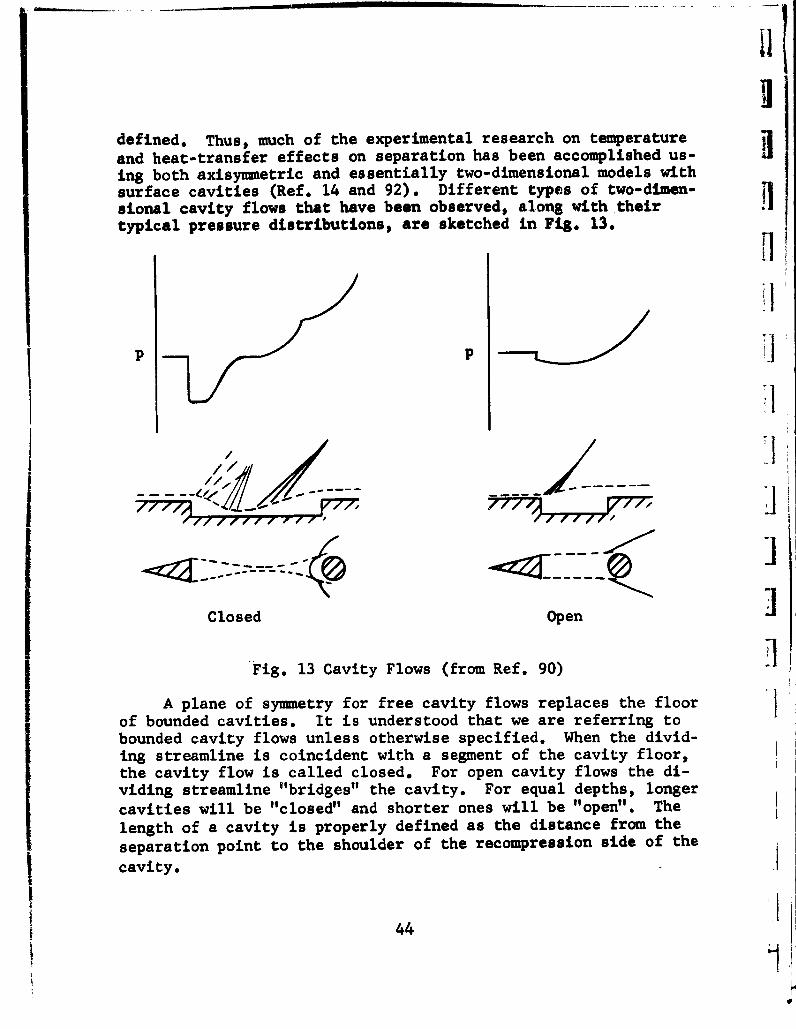
II
defined. Thus, much of the experimental research on temperatureand heat-transfer effects on separation has been accomplished us-ing both axisymmetric and essentially two-dimensional models withsurface cavities (Ref. 14 and 92). Different types of two-dimen-sional cavity flows that have been observed, along with their itypical pressure distributions, are sketched in Fig. 13.
1
j~j I, 1
/ / 1 I////
Closed Open
Fig. 13 Cavity Flows (from Ref. 90)
A plane of symmetry for free cavity flows replaces the floorof bounded cavities. It is understood that we are referring tobounded cavity flows unless otherwise specified. When the divid-ing streamline is coincident with a segment of the cavity floor,the cavity flow is called closed. For open cavity flows the di-viding streamline "bridges" the cavity. For equal depths, longercavities will be "closed" and shorter ones will be "open". Thelength of a cavity is properly defined as the distance from theseparation point to the shoulder of the recompression side of the
cavity.
44
! r
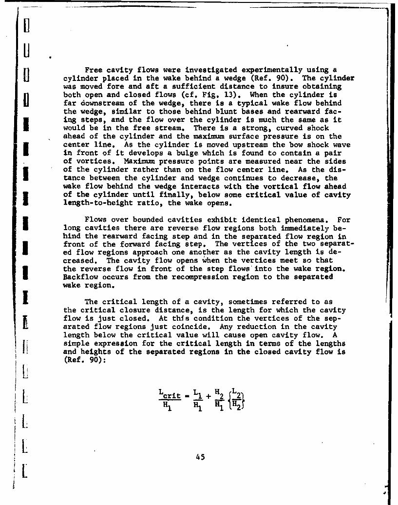
UFree cavity flows were investigated experimentally using a
cylinder placed in the wake behind a wedge (Ref. 90). The cylinderwas moved fore and aft a sufficient distance to insure obtainingboth open and closed flows (cf. Fig. 13). When the cylinder isfar downstream of the wedge, there is a typical wake flow behindthe wedge, similar to those behind blunt bases and rearward fac-ing steps, and the flow over the cylinder is much the same as itwould be in the free stream. There is a strong, curved shockahead of the cylinder and the maximum surface pressure is on thecenter line. As the cylinder is moved upstream the bow shock wavein front of it develops a bulge which is found to contain a pairof vortices. Maximum pressure points are measured near the sidesof the cylinder rather than on the flow center line. As the dis-tance between the cylinder and wedge continues to decrease, thewake flow behind the wedge interacts with the vortical flow aheadof the cylinder until finally, below some critical value of cavitylength-to-height ratio, the wake opens.
Flows over bounded cavities exhibit identical phenomena. Forlong cavities there are reverse flow regions both immediately be-hind the rearward facing step and in the separated flow region infront of the forward facing step. The vertices of the two separat-ed flow regions approach one another as the cavity length is de-creased. The cavity flow opens when the vertices meet so thatthe reverse flow in front of the step flows into the wake region.Backflow occurs from the recompression region to the separatedwake region.
I The critical length of a cavity, sometimes referred to asthe critical closure distance, is the length for which the cavityflow is just closed. At this condition the vertices of the sep-arated flow regions just coincide. Any reduction in the cavitylength below the critical value will cause open cavity flow. Asimple expression for the critical length in terms of the lengthsand heights of the separated regions in the closed cavity flow is(Ref. 90):
crit 1+H
2 LIH 1 H, Hi {H 2
K4
where the symbols, fer theabove equation, are de-fined in the adj'oining H T HFig. 14. Experimental .data for critical lengths L " 2correlated quite well us-ing the above equation, 30.1which is plotted in Fig.14. Data were obtainedfor turbulent boundarylayers ahead of both two-dimensional and axisymmet- 20rnc cavities; the criticallengths are independent of Lcrit IMach number and the shape Hof the recompression step Hi0 71(flat, wedge, and circu-lar steps were used). Thespread of experimental (/data about the correlation (curve shows a certain hys- 0teresis effect; i.e., the 0 1 2 3 4 5closure of open cavity H/Hflows occurs at a differ- 2 1ent value of Lcrit than Fig. 14 Critical Lengths forthe equivalent opening of Cavity Flows (Ref. 90)closed cavity flows. Thiseffect is more pronounced for axisymmetric than for two-dimensiomrl Jflows. For both types of flows, the hysteresis effect becomesmore pronounced as the depth of the cavities decreases below thethickness of the undisturbed boundary layer and as the ratio ofthe step heights varies from unity. There seems to be a definiteneed for stability analyses of such flows. Indeed* because ofthe common observance of three-dimensional and unsteady effectsin all cavity flows, it is almost fortuitous that two-dimensionalanalyses are useful at all.
A possible practical application of cavities is as a drag Igenerating device for hypersonic vehicles. Heat-transfer and dragdata for notched bodies of revolution indicate that the cavitiesgreatly increase the drag over that of the smooth bodies but atworst only moderately increase the average heat-transfer to thebodies; thus, the axisymnetric cavities substantially reduce the I
46
.4
average heat transfer per unit drag (Ref. 91). The average heattransfer to the surface for open cavity flow, for cavity depthsgreater than the boundary layer thickness, is about half that ona corresponding smooth wall. Only for very shallow cavities isthe average heat transfer increased slightly above the smooth-wall value. The drag of a notched body, however, for open cavityflows, is an order of magnitude greater than that of the smoothbody. For the notched surfaces considered (short enough to haveopen cavity flow), the great increase in drag led to the resultthat the average heat transfer per unit drag to the notched wallwas about one-twentieth of that of a smooth wall.
Heat-transfer experiments were conducted on axisymnetric andessentially two-dimensional flows over models with and withoutsurface cavities in order to substantiate the theoretical resultspresented on pages 19 and 20 (Refs. 14 and 92). The tests wereconducted in supersonic flows with free stream Mach numbers up tofour. The sharp internal corners of the two-dimensional and axi-symmetric cavities were filleted in some instances, with negli-gible effect on the measured heat-transfer rates. For two-dimen-sional flows, the average heat transfer to the cavity for separatedlaminar boundary layers was about 56% of the average heat trans-fer to the equivalent portion of the smooth surface with an attach-ed laminar boundary layer. This value was found to be independentof both Mach and Reynolds numbers and was in excellent agreementwith the theory. The average heat-transfer rate to the cavityfor turbulent boundary layers was about 60% of the value of theattached turbulent boundary layer. As noted on page 20, this re-sult contradicted the theoretical prediction that separation ofa turbulent boundary layer would greatly increase the averageheat-transfer rate. The average heat transfer to the axisymmetriccavities followed the same trend as for the two-dimensional flows;for both laminar and turbulent separation the average heat trans-fer is about 60% of that for attached flows. The heat tansferin the immediate vicinity of reattachment, however, is two tothree times larger than that of the attached flow at the corre-
I sponding point on the surface, and moreover, remains higher fardownstream of reattachment. Thus, when considering separation toreduce heating, although the large heat-transfer rates for the
Sinitial portions of attached boundary layers may be greatly re-duced, allowance must be made for the higher heat-transfer ratesat and downstream of reattachment. As Sprinks (Ref. 56) and sev-
L eral others emphasize, there are no adequate theories and few em-
pirical data for the effects of separation on temperature and heat
L47L

transfer; even less is known about the effects of temperature andheat transfer on separation.
A notable difference between separated and attached laminarboundary layers is that transition in the separated layer is movedupstream by cooling the wall. For marginally open cavity flow,cooling the wall causes the flow to close so that the flow isattached on part of the cavity floor. As for attached boundarylayers, the stability of laminar layers increases with streamMach number. Another observed aspect of the stability of separatedlaminar boundary layers it; that cavity flows exhibit an importantunsteady resonance effect which can greatly decrease the value ofthe transition Reynolds number (Ref. 92).
Experimental investigations of resonance effects were madeusing rectangular cavities in a flat plate and in the cylindricalportion of an ogive cylinder (Refs. 93 and 94). As expected, thepressures on the cavity floors dropped below the stream value nearthe front of the cavity and increased to yield positive pressurecoefficients near the end of the cavity; the distributions weresimilar to the "open" cavity flow pressure distribution sketchedin Fig. 13 on page 44. The variation of the pressure coefficientaway from zero decreased as the Mach number increased from 2 to5 so that, at Mach 5, Cp - 0 throughout the cavity. The fre-quencies of the unsteady flow, which have been responsible forstructural failure in cavities in flight vehicles, are inverselyproportional to the length of the cavity for all stream Mach num-bers (Ref. 93). The frequencies are conveniently presented innondimensional form using the Strouhal number (St c (frequency)x (cavity length) / (free stream velocity).
Axisymmetric Bodies
The review of separation phenomena associated with flows overaxisymmetric bodies commences with the apexes of the bodies andconcludes with their bases. Flow separation spikes, separationahead of conical flares, and axisymmetric base flows are describedin the listed order.
Flow separation spikes, mounted in front of blunt bodies,may possibly be used to effectively streamline the body, therebyreducing the heat-transfer rate and drag of the body (Refs. 95
48

III
through 98). The flow separates on the spike ahead of the bluntbody in much the same manner as flow separation ahead of a step.Thence, according to the length of the spike with respect to thediameter of the body, the effective nose shape of the body ischanged to a more pointed, higher fineness ratio nose, which isessentially conical. The early experimental work of Stalder and[ I Nielson (Ref. 95) gave results which were disheartening at firstglance. The pressure drag was reduced by as much as 45% but thecorresponding average heat transfer to the nose was approximatelydoubled. The increase in heat-transfer rate to the forward por-tion of the blunt body when the spikes were used was due to thetransition of the separated boundary layer. It was turbulent
1 when it reattached, and thus resulted in higher heat-transferrates than did the laminar layer that existed on the blunt bodyalone. The later experiments of Bogdonoff and Vas (cf. Refs. 96and 97) clearly indicate that the separated layer may sometimesremain laminar and therefore greatly reduce the average heattransfer to the nose. The spikes used by Bogdonoff and Vas aresharp, needle-like, cone cylinders with diameters very small incomparison with the diameter of the blunt body. The blunt bodiesare hemisphere-cylinders and flat-nosed cylinders. The importantparameter to be varied is Ra, which is the ratio of spike lengthto body diameter. High-speed oscillations of the nose shock(frequencies of about 10 kc) were observed for values of Ra lessthan about 3. The shock moves forward with the tip of the spikefor these small Ra values. Around Ra = 4,the flow separates fromthe surface of the cylindrical portion of the spike, and contin-ues to do so as the spike length is extended still further. Ex-amples of the drag and heat reduction possible, although the dataare from Mach 14 tests in helium, are: for a hemisphere cylinder
li with a spike having Ra - 4, the form drag is one tenth and theaverage heat transfer one third of those for the body without aspike; for a flat nosed cylinder with the same Ra - 4 spike, the
I form drag is one fortieth and the average heat transfer one halfof the "unspiked" values (Ref. 96). Lynes and Schaaf presenttheir experimental results of spiked bodies in Ref. 98. A hemi-spherically capped cylinder is moved in and out through a conicalfrustrum of 450 semivertex angle in a Mach 5.9 air flow. The en-tire flow is initially separated between the hemisphere and theb •cone, but as the hemisphere cylinder is pushed out, separationthen occurs at the shoulder of the sphere until for greater cy-linder lengths the flow separates from the surface of the cylinder.
L Reattachment is close to the base of the cone. It is noted that
4I 49

no hysteresis in the location of separation was found as the cy-
linder was pushed out and then returned to the same position; !!stability of the separated flows, at least macroscopically, is
thereby indicated.
Work of a similar nature is known to be under way by Chapmanand his co-workers at the NASA Ames Research Center. A consider-able range of Mach and Reynolds numbers is being employed intests of blunt, axisymmetric bodies with and without spikes. Ingeneral, it appears that spikes will provide a considerable de-gree of drag and heat-transfer reduction, and a simple means ofproducing large control forces in certain specific applications(primarily laminar flow). Certain conditions produced large-scale unsteadiness which would be catastrophic in a flight ve-hicle, indicating that considerably more work is necessary beforethis interesting approach can be properly exploited. i
Extensive flow separation may occur ahead of conical flares,such as those commonly employed in multistage rockets, and dras-tically affect the aerodynamic characteristics of such vehicles.Structural simplicity and aerodynamic stability considerationsfor Saturn type configurations led to the use of cylindrical seg-ments joined by conical flarings. Hence, there is much current Ainterest in investigating high-speed flows over these configura-tions (cf. Refs. 99 through 101). Separation in the axisymmetriccylinder-cone compression corners can substantially alter theheat transfer and drag of the vehicle, can cause drastic shiftsin the center of pressure, and, if unsteady, can cause catastro-phic Oscillations. Reattachment near the bases of the conicalfrustums can cause extremely high local heating. As for two-dimensional separated flows, the character of the boundary layeris most important in determining the region of separation andmust be accounted for in any wind tunnel investigations. Laminarseparation may be expected far upstream of the cylinder-conejunction whereas the extent of turbulent separation would be muchsmaller with smaller changes in the inviscid pressure distribution.The unsteadiness of transitional separation must be avoided, per-haps by forcing early transition. Separated flows ahead of coni-cal flares are qualitatively comparable to separated flows ahead
of two-dimensional ramps; quantitative results or comparisons arestill not available.
50r 50
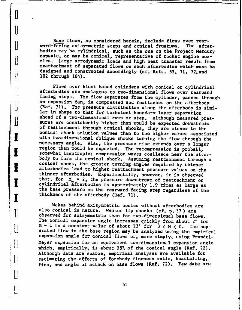
Base flows, as considered herein, include flows over rear-ward-facing axisymmetric steps and conical frustums. The after-bodies may be cylindrical, such as the one on the Project Mercurycapsule, or may be conical, representative of rocket engine noz-[zles. Large aerodynamic loads and high heat transfer result fromreattachment of separated flows on such afterbodies which must bedesigned and constructed accordingly (cf. Refs. 53, 71, 72,andI I 102 through 104).
Flows over blunt based cylinders with conical or cylindricalafterbodies are analagous to two-dimensional flows over rearwardfacing steps. The flow separates from the cylinder, passes throughan expansion fan, is compressed and reattaches on the afterbody(Ref. 71). The pressure distribution along the afterbody is simi-lar in shape to that for turbulent boundary layer separationahead of a two-dimensional ramp or step. Although measured pres-sures are consistently higher than would be expected downstreamof reattachment through conical shocks, they are closer to theconical shock solution values than to the higher values associatedwith two-dimensional oblique shocks turning the flow through thenecessary angle. Also, the pressure rise extends over a longerregion than would be expected. The recompression is probablysomewhat isentropic; compression waves coallesce near the after-body to form the conical shock. Assuming reattachment through aconical shock, the greater turning angles required by thinnerafterbodies lead to higher reattachment pressure values on thethinner afterbodies. Experimentally, however, it is observedthat, for M - 2, the pressure downstream of reattachment oncylindrical wfterbodies is approximately 1.9 times as large asthe base pressure on the rearward facing step regardless of thethickness of the afterbody (Ref. 71).
Wakes behind axisymmetric bodies without afterbodies arealso conical in nature. Weaker lip shocks (cf. p. 37 ) areobserved for axisymmetric than for two-dimensional base flows.The conical expansion angle increases quickly from about 20 forM - 1 to a constant value of about 130 for 3 < M < 8. The sep-arated flow in the base region may be analyzed using the empiricalexpansion angle for conical flows or, more simply, using Prandtl-Meyer expansion for an equivalent two-dimensional expansion angleI! which, empirically, is about 85% of the conical angle (Ref. 72).Although data are scarce, empirical analyses are available forSestimating the effects of forebody fineness ratio, boattailing,fins, and angle of attack on base flows (Ref. 72). Few data are
LL 51

available for het-transfer rates in wakes behind axiasymetricbodies (Ref. 102).
Experimental Techniques
Because of the lack of dependable theoretical methods, ex-periments are of paramount importance in investigations of sep-arated flows. Most of the theoretical methods in use rely tosome extent on empirical knowledge, and design calculations mustinvariably be supported by experimental verification for the speci-fic situation involved. Particularly for separated flows is itadvisable to employ a few different types of experimental tech-niques for the same situation: static pressure measurements,boundary layer probing, skin friction measurements, adiabaticwall temperature measurements, china clay or oil film or dropplettechniques, shadowgraph observations, schlieren photographs, high-speed motion pictures, and others.
Static pressure measurements give an indication of the typeof separation and the regions of separation and reattachment, butit is often quite difficult to determine experimentally the ex-tent of separation with static pressure measurements alone. Theuse of other experimental techniques to complement static pressuremeasurements is particularly important in the case of laminarboundary layer separation. The small pressure rise required tobring about laminar separation is not readily detected; particu-larly in the presence of other effects, such as blast wave orviscid interaction effects, which are prominent in low-Reynoldshigh-Mach number flows, the separation zone might be obscured.Pressure distribution measurements can, however, bring out manysalient features of the flow and are a must in any comprehensiveinvestigation of separated flows.
Probing the boundary layer is tedious and rather prohibitivefor a large scale investigation. In employing this technique we relyon past experience in knowing the shape of the velocity profilesfor laminar, turbulent, and separated flows and thus determinefrom velocity profiles the nature and location of separation and
reattachment. "T" probes may be used to simultaneously measurethe streamwise and also the reverse flows. If we are interestedin locating just the point of transition from laminar to turbulent,we can do so by placing a total pressure probe near the wall.
52
U When transition occurs, the pressure reading jumps because thevelocity head is higher near the wall for a turbulent boundarylayer. Of course, caution must be exercised to place the probein the appropriate location.where the difference in velocity headbetween the laminar and turbulent layer is more pronounced (cf.II Ref. 106).
Skin friction measurements can be made either directly byusing a floating element or indirectly by probing the boundarylayer. The floating element technique, however, also becomestedious. One may calibrate a Stanton tube versus a floating ele-u ment and use the Stanton tube as a skin friction measuring device(cf. Ref. 35). Knowing the skin friction, we can determine thenature of the boundary layer and the points of separation andreattachment,
Temperature and heat-transfer measurements may also be usedin determining the nature of the boundary layer. Their use for Idetermining regions of separated turbulent flows, however, isseverely limited due to the lack of understanding of temperatureand heat-transfer effects (cf. pp. 19 and *'.*7 ). China clay, oil
I Ifilm, or oil dropplets may be used to determine the extent of sep--aration because of the reverse flow near the wall in separated
I flow regions.
The shadowgraph technique is quite useful in distinguishinglaminar and turbulent boundary layers and in determining the re-gion of transition (cf. Refs. 3, 4, and 107 through 109). Inbrief, at low static tunnel pressures and small film-to-model dis-tances, transition occurs at the end of the so-called laminarwhite line (which is described in Fig. 15 on the following page).At high tunnel static pressures with small film-to-model distances,Sor arbitrary tunnel pressures 'but large film-to-model distances,the laminar white line appears displaced from the surface by alarge distance compared to the boundary layer thickness b. Thisdisplacement is almost constant for laminar flat-plate flow. Asthe Reynolds number increases to the point where transition be-gins, the white line starts converging on the surface and appears
I tangent to the surface when transition is completed.
Lastly we mention that from high-speed motion pictures, wecan get a qualitative picture of the flow field and determine thesteadiness of the separated region. Shock waves interacting with
53

I The shadow effect responds approximately to second deriva-tives of the density with respect to the axes perpendicularto the light beam. The laminar white line corresponds, there-fore, to the negative second derivative in density that exists !at the edge of a laminar boundary layer. For turbulent bound-ary layers the negative second derivative has smaller absolutevalue and is found to be near the wall. Hence, the conver-gence of the laminar white line to the wall and its disappear-ance at the wall in the turbulent zone.
TI
Fig. 15 xmThe Laminar White Line
54
I!
boundary layers are not necessarily stable but oscillate about amean position (Refs. 87 and 88). Frequencies may be of the orderof 2,000 cycles per second (Ref. 89) which can be stopped usinghigh-speed motion pictures of either the shadowgraph or schlierenfields.
This short presentation is included here as an introductionto experimental techniques used in separated flow investigationsand is not by any means exhaustive. For further information onthe topics mentioned and others, the cited references should beconsulted.
IIIII
lii
L
LILI 55
A.
IIINFLUENCE OF SEPARATION ON CONTROLS
Control characteristics, particularly at hypersonic speeds,are often greatly affected by separation. Control effectiveness ]may be increased, limited, or may be completely nullified becauseof boundary layer separation. Pressure distributions over con-trols and on the basic configuration may be greatly altered due Ito separation effects, changing drastically the moment coeffi-cients predicted by inviscid theory. Heat-transfer rates arechanged on the control surfaces and on the basic configuration Iboth upstream and downstream of the control. Separation effectsmust therefore be considered in both the design and location ofcontrols. In general, separation tends to smooth out the sharp Ichanges in pressure distributions predicted by inviscid theory,and can cause local "hot spots" which have heat-transfer ratesmany times higher than those that would exist for attached bound- Iary layers. Separated flow phenomena are frequently unsteady andthree-dimensional in nature, and undergo large changes with transi-tion from laminar to turbulent flow, further complicating theanalytical treatment of a design. rhus, for example, hysteresiseffects are noticeable in the Cm versus a curves for some controlconfigurations.
Aerodynamic forces and moments on a vehicle may be changedas much by changing the pressure distribution on the basic con-figuration as they would be by changes in the normal forces act-ing on controls. Leading edge controls, for example, usually arenot directly influenced by separation but, by causing separation,they can affect the pressures and heat-transfer rates over theentire configuration. Some effects of separation associated withcontrols on windward and leeward surfaces are described below.Important three-dimensional and unsteady flow effects of separa-tion on control characteristics are presented at the conclusionof this short section.
Leading-Edge Controls
Leading-edge controls contemplated for hypersonic vehiclesinclude flaps, spoilers, fins, spikes, and all-movable noses.The importance of separation for such controls is in the influence
56
on the entire flow field downstream of the control. SeparationSbehind a deflected leading-edge flap makes any control or stabi-
lizing surface downstream of the flap ineffectual. Heat-transferrates on the surface are reduced in the separated-flow region,
j but if the boundary layer reattaches on the surface the heat-transfer rate at reattachment can be several times larger thanthat for an attached boundary layer. The control forces and hingeI moments of leading-edge fins and flaps would not be directly in-fluenced by separation. Fins, which may be canards, create strongvortices which can cause boundary layer transition and contributeto the possibility of unsteady flow over the downstream surfacesof the configuration. Comparable effects would be expected forlarge amounts of all-movable nose deflection which, nevertheless,is anticipated to be a very effective trimming device at high an-gles of attack. The importance of leading edge controls in in-fluencing the entire afterbody is epitomized by the use of spikes.Hj Flow separation spikes in front of blunt bodies may reduce thetotal drag of the body by effectively streamlining it. Averageheat-transfer rates in the separated flow region created by thespike are significantly reduced in laminar flow, although thelocal heat transfer rate at reattachment may be quite high. De-flectable spikes might be used as control devices because theyalter the pressure distribution in the forward region of a body.This technique is also being studied at NASA Ames Research Center.
The separated flow region caused by spikes, however, is frequentlyunsteady, which is a most unsatisfactory control characteristic.If these problems can be worked out, spike controls could become
a very effective system for blunt vehicles.
Downstream Controls
Frequently control surfaces located downstream of the lead-
ing edge may also be used as stabilizing devices. Their effective-ness, however, may be greatly affected by upstream separation ofthe boundary layer. The inviscid estimate of the pressure risedue to deflecting a control into the local stream is a discontin-uous jump in the pressure distribution on the surface at the lead-ing edge of the control. A similar sudden increase in the in-
viscid pressure distribution occurs at the trailing-edge shock re-Ii quired to recompress the flow over an expansion surface. In theactual flow, the sudden pressure rise may be transmitted upstream
Sthrough the subsonic portion of the boundary layer. Particularly
for hypersonic flow, where shocks are highly swept, and for laminar
57L

boundary layers, which have thicker subsonic portions than tur-bulent boundary layers, the pressure rise may be felt, and sep-aration may occur, far upstream. Depending upon flow conditions,the boundary layer may be separated over the major portion of thesurface thereby greatly influencing the effectiveness of controls 1located downstream on either compression or expansion surfaces.
Laminar boundary layer separation ahead of a deflected flapon the windward surface of a vehicle spreads the flow-deflectionpressure rise over a much larger region than does turbulent sep-aration. The effectiveness of the flap in creating a moment is
lessened both by the decrease in the pressure distribution on theflap and by any pressure increase occurring on the surface up-stream of the rg,. These effects tend to restrict the desired Irearward movement of the center of pressure and reduce the effec-tiveness of the control. In extreme cases the center of pressurelocation with laminar separation may be well forward of that fora turbulent boundary layer.
The extent of the separated-flow region, and the pressuresimposed on the surface depend on the flap deflection, flow con-ditions, and nature of the boundary layer ahead of theflap. Reattachment of the separated flow on the flap is usuallyaccompanied by a local heat-transfer rate several times largerthan that corresponding to an attached boundary layer; the average
heat transfer to the separated flow region, however, is reduced.Similarly, separation affects the pressure distribution on vehiclesfhaaving flared-skirt-type stabilizing surfaces. Laminar boundarylayer flow ahead of small protuberances yields pressure distribu-tions closer to the inviscid predictions than does turbulent flow.A small step on a surface is effectively streamlined by laminarseparation far ahead of it, whereas for turbulent separation, astrong shock exists ahead of the step and there is a large in-crease in the local pressure.
Separation on the leeward side of a vehicle may make shieldedcontrols (i.e., controls which no not "see" the free stream) use-less. A few factors combine in making leading-edge separation £from the leeward surface of hypersonic vehicles particularly pro-bable. Large angles of attack may be desirable for many hypersonicflight paths. Because high Mach number flows have small limiting Iexpansion angles, much of the upper surface feels only the leakage
flow from the boundary layer where the Mach number is lower. The
pressure rise due to the strong trailing-edge shock may be propa-gated far forward through the thick hypersonic boundary layer and
58 I

[1enhances the possibility of leading-edge separation. Another factorHenhancing the probability of separation is the likelihood of theboundary layer being laminar with consequently thicker subsonicregions and simultaneously less ability to overcome an adverse1 pressure gradient than ýhe corresponding turbulent boundary layer.The effectiveness of controls located entirely within the separat-ed flow region, such as trailing-edge flaps or fins, would be nul-lified. On the other hand, flow separation over notches (cavities)may advantageously be used to control the drag of a hypersonicvehicle; for essentially the same average rate of heat transferto a hypersonic vehicle, the drag may be increased by an order ofmagnitude by the employment of notches in the surface of the ve-hicle. Separation influences both the type and the location ofcontrol devices. Spoilers, for example, would be ineffectual onleeward surfaces of hypersonic vehicles even if they were nearthe leading edge. Positive controls that always "see" the freestream are required.
SThree-Dimensional and Unsteady Flow Effects
Separated-flow regions rarely are purely two-dimensionaland usually are unsteady. Although much insight into separationphenomena may be gained using two-dimensional flow analyses, thereare important effects that must be considered three-dimensionally.II One such effect is the large venting of the separated region infront of a ramp of finite span. The fluid in the separated re-gion, having low velocity and (relatively) high pressure, expandsreadily into the low-pressure stream at the tip, and the massbalance of the two-dimensional separation is upset. Another case
S r is that associated with the streamwise flow in the corner at theL juncture of a fin and the surface of the configuration. A strong
vortex may be set up in such a corner with extreme rates of heattransfer associated with the vortical motion. Another importantthree-dimensional effect is the coupling effect of a controlon another surface. The shock wave ahead of a blunt control or
1i ahead of a separated flow region may impinge on a transverse sur-face. Thus, the deflection of a vertical fin or rudder may causenonsymmetrical separation on the horizontal surface and create anundesired rolling or pitching moment. Particularly for separationoccurring near the point of transition of a laminar to turbulentboundary layer, the point of separation and the associated shockwave may oscillate about some mean position. Large buffeting
L559
L

loads may be experienced on the surface and on adjoining surfacesof the configuration. Unsteady flow in cavities in the surface ofa missile may also cause structural failure. Laminar boundarylayer separation with large center-of-pressure shift may be ex-perienced at a small control deflection, while if the deflectionis increased and then decreased to its initial value the separa-tion may be turbulent with a far different value of pitching mo-ment because of the different center-of-pressure location. This Ihysteresis is extremely difficult to predict, and can be quitedangerous. "1
AIIIIII
IIII
60
V-1, iW
'Ii
CONTROLS FOR HYPERSONIC VEHICLES
The current status of the application of aerodynamic controlto hypersonic flight is reviewed in this section. We discuss theexisting information on problems of controlling a hypersonic ve-hicle and of estimating aerodynamic control characteristics, andpresent, in the Appendix, a synopsis of the experimental informa-tion on controls which is available in the literature. The tabu-lation lists the types of controls tested, the vehicle configura-
Hj tions on which the controls were tested, the test conditions, the
type of data obtained and comments concerning special features ofthe work in each case. This table should serve as an index tothe available hypersonic controls data.
'IGeneral Discussion
Controls are required to provide maneuvering capability forflight vehicles and can supply the aerodynamic stability and trimnecessary to maintain an equilibrium flight trajectory. The mosteconomical and straightforward type of control for a vehicle fly-ing the atmosphere is usually an aerodynamic surface, but the ap-plication of aerodynamic control surfaces to hypersonic flightvehicles presents many formidable problems. For flight at veryI high altitudes aerodynamic controls may be rendered ineffectiveby low dynamic pressure and very thick boundary layers. At thelower altitudes the deflection of a control can generate separatedflow regions over much of the surface of the vehicle and alterthe aerodynamic load distribution and stability characteristics.
Standard aerodynamic stability and control problems are great-ly aggravated by the large range of angle-of-attack (cf. Ref. 110),high aerodynamic heating rates, and the wide speed range to beencountered by hypersonic flight vehicles. These vehicles alsotend to have compact geometries and therefore require high controlloads to produce useful moments about the center of gravity. Con-sequently, the controls tend to become a significant portion ofthe vehicle's structure and it becomes desirable to build more
[9 functions into fewer control surfaces.
The complexity of flow fields about hypervelocity flight[9vehicles arises from the interplay of many distinctive hypersonic
611.

flow phenomena. The blunt leading edges, which are usually neces-sitated by aerodynamic heating considerations, lead to strong de-tached shock waves with their attendant high loads, thick entropylayers, and steep pressure gradients. Much of the surface of theconfiguration is in close proximity to the highly curved bow shock,Separation and reattachment of the thick boundary layer, secondaryshocks, and locally unsteady flow may further complicate analysisof the flow field.
Trailing-edge controls may be rendered useless if they areshielded from the free stream by the basic configuration. Or, )they may be subjected to much larger loads than they would experi-ence if they were in the free stream in the absence of the basicconfiguration. In the latter case, the flow may be compressed -
through weak oblique shocks generated by the basic configuration,with consequent lower pressure losses and less of an entropy rise,so that the pressure coefficient on the trailing-edge control sur-face may be much larger than even the stagnation pressure coeffi-
cient that would be measured by a total pressure tube in the freestream. Trailing-edge controls may cause the boundary layer toseparate far upstream of their hinge lines, thereby affecting thepressure distribution over the vehicle, and may be subjected tolocal increases in heat-transfer rate by reattachment or unsteadi-ness of the boundary layer. On the other hand, a control locatedforward of the c.g. is subjected to severe loads and heating, andchanges the flow field over a large part of the vehicle. It canthus adversely effect any downstream controls or stabilizing sur-
faces.
Available theoretical methods (cf. Refs. 110 through 127)leave much to be desired. The important viscid effects must usu-ally be omitted from the analysis.,and furthermore, many methodsare based on the supersonic linear theory which, by definition(cf. Ref. 53), fails for hypersonic flows. The flow field abouta vehicle may be approximated to varying degrees of accuracy de-pending upon the complexity of the configuration and the applic-ability of the methods available. Although the method of char-acteristics is available, it cannot always be applied. The ef-fects of sweep, incidence, and surface discontinuities force oneto rely upon much simpler approximate approaches, such as Newton-ian and integral methods, the blast wave analogy, and viscid in- Iteraction corrections, which often require experimental verifica-tion and the use of empirical data (cf. Refs. 110 and 123 through
169). The best possible estimate of local flow conditions im-
mediately ahead of controls at large deflection angles should be
62 V

I] - I
used in calculations, rather than free stream conditions. Highpressures and high heating rates, approaching and even exceedingthe body stagnation value, may be experienced on controls (cf.Ref. 170). Heat-transfer calculations for both sharp and blunt
11 leading-edged delta wings can probably be performed adequatelyusing simple strip, streamline divergence, or crossflow theories(Ref. 160),
Most of the theoretical methods currently employed are notcompletely satisfactory in that they involve the knowledge, "apriori", of some empirical data, and they give no clear indicationof the limits of their validity. Experimental data for hypersonicflows are still quite scarce and the data which do exist cannotbe extrapolated to differing flow conditions with any degree ofcertainty. A great deal of the experimental information available,on relatively simple shapes, results from helium tests (cf. Refs.66 and 163). The use of helium for verification of theoreticalmethods may improperly eliminate some theories that are more close-ly applicable to air. The proximity of the entire shock to thebody surfaces, boundary layer growth, interaction, real gas ef-fects, and the structure of the entropy layer are all dependentupon the gas used.
Flaps
Only a small fraction of the available experimental data ontrailing-edge flaps are applicable to hypersonic problems. Two-dimensional data on an unswept wing-trailing edge flap configura-tion, pres'ented in Refs. 171 through 174, cover the Mach numberrange frot 1.62 to 6.9 for angles of attack up to 100 and controldeflection's from -16' to +160. Section lift, drag, pitching mo-ment, and hinge moment coefficients are presented, as well as
Ii chordwise pressure distributions. A more general program to de-i termine control effectiveness, which includes the effects of trail-
ing-edge flaps, is presented in Refs,, 175 through 107. This pro-gram, although extremely comprehensive in that it investigatesthe effectiveness of a wide variety of flaps, spoilers, and tipcontrols individually and in combination on trapezoidal and tri-angular planform wings, is limited to supersonic Mach numbers be-tween 1.6 and 2.4. The data provided in this program are lift,drag, pitching moment and hinge moment coefficients, as well as
[ij pressure distributions on the wing and on the controls. In these
6
63
L2

reports only wings and controls are considered; the following dis-
cussion deals with thoseinvestigations which treat a completevehicle, usually comprising a wing, body, and vertical fin,
Data on the effectiveness of trailing-edge flaps on variousconfigurations in supersonic flows are presented in Refs. 1301
through 195. In particular, Refs. 183 and 194 supply effective-ness information on delta-wing configurations for high angles of Iattack and large flap deflection angles. Both reports indicatethat at high angles of attack and large deflection engles thecontrol effectiveness decreases sharply. The effect of varying ]the Mach number from supersonic to hypersonic on configurationswith different wing planforms and sweep angles can be found inRefs. 196 through 200. Flap effectiveness data at hypersonic ,Mach numbers, on the various configurations, are presented inRefs. 196 through 204. Experimental investigations of flaps onpyramidal configurations are reported in Refs. 204 and 205. As Iexpected, the longitudinal effectiveness of flaps decreases withincreasing dihedral angle while the lateral effectiveness in-creases with increasing dihedral angle. In Ref. 206 data are pre-sented for a wide variety of wing, wing-body, and wing-body-flapconfigurations tested over the Mach number range from 2 to 22.This report represents an exploratory effort to determine the use- 1fulness of aerodynamic controls under hypersonic flight conditions.
Aerodynamic heating data for trailing-edge flaps in supersonicstreams are presented in Refs. 207 and 200. Heat-transfer datafor hypersonic flow over a trailing-edge flap are presented inRef. 209. These data are limited in their extent and usefulness.The problem of aerodynamic heating of wing-type configurationsusing aerodynamic controls is an extremely serious one. At pre-sent it is virtually unexplored, This lack of information is aserious handicap to the reliable design of hypersonic flight ve-hicles.
Fins
Another aerodynamic surface capable of providing maneuvering
and stabilizing capabilities is the deflectable fin mounted eitherfore or aft.L
64

The supersonic characteristics of canard controls, mountedon flight configurations having delta or trapezoidal planformwings, are presented in Refs. 192, 193, and 210 through 214.
Some data for hypersonic flows are presented in Ref. 206. Thesereports indicate that effective canard surfaces can be designedto provide longitudinal control in the supersonic Mach numberrange. There are not enough data to Justify such a conclusionI at hypersonic Mach numbers. The heating, separation, and down-wash problems associated with canard surfaces at hypersonic speedshave not been investigated. The usefulness of canard surfacesunder hypersonic flight conditions will depend strongly on theseeffects.
j The effect of Mach number variation, from supersonic to hyper-sonic, on the effectiveness of aft fins, mounted both verticallyand horizontally, is presented in Refs. 197 through 199, 206 and215. Additional empirical data for aft-mounted fins are presentedin Refs. 190, 192, 201, 213, and 216 through 223. As may be. seeni in the Appendix, aerodynamic heating data on fins are presented
in Refs. 207 through 209.
The effectiveness of deflected wing tips, tested at supersonicMach numbers, is presented in Refs. 171, 175 through 177, 179,182, 185, 186, 183, 139, 224, and 226 through 230. Hypersonicdata are presented in Ref. 225. Test conditions and the types ofdata available in the reports are indicated in the Appendix. Thedata available indicate that tip controls can be designed to pro-vide aerodynamic control for supersonic flight vehicles. Thehypersonic usefulness of these controls cannot be ascertained un-
til the aerodynamic heating problems associated with them are in-vestigated.
Others
Control effectiveness information on tip-mounted bodies suchas cones, pyramids, and tri-panels, is presented in Refs. 200, 203,and 221. A direct comparison of the control effectiveness ofthese tip mounted bodies, at a hypersonic Mach number, is madein Ref. 203, while the Mach number dependence of the control ef-fectiveness is shown in Ref. 200.
LL
65
t

d
Other aerodynamic surfaces usable for control and stabili-zation fall into the general categories of nose spikes, canted 1noses or drooped leading edges, spoilers, and flares. Many prob-lems arise connected with the use of these more unconventionaltypes of controls. For example, the flow pattern about nose spikesis frequently unstable (Ref. 231). Nose cant enables trimming avehicle at high angle of attack but, unless the nose is movable,does not provide maneuvering capability (Refs. 194, 200, 203: 204v I205, 216, 217, 231 and 232). The effectiveness of spoilers in de-creasing the lift on the upper surface of a wing in transonic andsupersonic flows is presented in Refs. 176, 179, 180, 181, 185,
196, 226, 233,and 234. Spoilers on the upper surface of hyper-sonic vehicles, at angle of attack, would be operating in a verylow-pressure region, and would be useless. The use of spoilers onthe compression surface to produce additional force, remains tobe adequately investigated. Flares are basically stabilizing de-vices, although movable flares, theoretically, could be used for Icontrol (Ref. 216) if mechanical problems could be overcome.
The experimental information available for hypersonic flows Iis generally in the form of force data on particular configura-tions. The most important point to remember in a survey of these -•
data is the tremendous number of geometric variations character- jistic of the different approaches to design of hypersonic flightvehicles. The probability of finding tests on a specific practi-cal geometry in a given flow regime is indeed small, and attemptsto provide a catalogue of allcontrol problems of possible interestwould be grossly inefficient in terms of the cost of the tests. "|We feel that the only reasonable approach to this problem is acoupling of: 1) an increased theoretical understanding of funda-mental flow phenomena, 2) experiments on simplified geometrieswherein separate effects can be isolated, 3) experiments on typi- Ical types of interactions among different flow phenomena broughtabout by superposition of geometries, 4)a catalogue of those ex-periments which have been conducted for other purposes, and 5)final testing of a design which is created using the informationin items 1) through 4). Our purpose in this contract is to pro-vide some of the information needed to apply this approach.
66

CONCLUSIONS AND RECOHMNDATIONS
This section contains a brief statement of the present statusSof hypersonic flow separation and control problems. Detailed de-
scriptions of the phenomena and results of investigations are pre-sented in the preceding sections. General conclusions, based onthe knowledge accumulated for separation and control, are made be-fore recommending particular areas of the problems where much fur-
i ~ther work is required.
Our knowledge of separation is almost completely limited toS*flows below hypersonic speeds. Data on hypersonic flow separation
problems are only beginning to appear, and most of the existingtheories do not include such important hypersonic phenomena asf Kthe nonlinearity of the flow equations and the effects of varia-tions in fluid properties at very high temperatures (real gas ef-fects). We have tried to present what information is available,1 because theories for hypersonic flow separation will most probablybe constructed along the same lines as those for supersonic cases,
and the qualitative nature of the flows in the two cases will besimilar.
The shapes of the pressure distributions over laminar and tur-bulent separated flow regions, and the effects of pressure in-creases on laminar and turbulent boundary layers are qualitative-ly known on windward surfaces. The location of transition of theboundary layer from laminar to turbulent flow substantially affectsseparation but is quite difficult to predict. Lengthy theoreticalmethods are available for separated laminar boundary layers, butthere are serious limitations on their applicability and validity.Empirical methods are available for both laminar and turbulentseparated boundary layers. The methods may be used to predict re-gions of separated flow and the resulting pressure distributions.Separated flows over leeward surfaces may be of much greater ex-tent and are less amenable to theoretical methods, but also areusually less important because of the low pressures on leewardsurfaces at hypersonic speeds. Temperature and heat-transfer ef-fects on laminar boundary layers over simple shapes are understoodonly qualitatively, and the effects are not even qualitatively
I. understood for turbulent boundary layers.
667
L|
I
Analyses of boundary layer separation effects on the charac-teristics of various types of aerodynamic controls are complicatedby three-dimensional effects and interaction between configurationcomponents. The existing data on the relative importance of thevarious parameters is sparse, and the effects of different con- Ifigurations on control characteristics have not been compared.It is generally agreed that a control should not be shielded fromthe free stream and that an empirical approach is still requiredfor each new control configuration. Available control data areindicated in the Appendix.
Although additional work in practically all areas of hyper-sonic flow separation is required, we believe the following needspecial attention:
The importance of violations of the Prandtl boundarylayer assumptions should be evaluated, and solutions ofboundary layer equations including additional terms im-portant for hypersonic flows should be developed, evenif only approximately.
The better theoretical and semiempirical methods forsupersonic separated flows should be extended to include Ihypersonic phenomena of nonlinearity, real gas effects,stronger shock interactions, and large transport proper- Ity variations. b
Additional experimental research is required to under-stand better the relationship between boundary layertransition and separation.
Both theoretical and experimental research should beaccomplished to determine the influence of wall tempera-ture on separation and the effects of separation on heat-transfer rates.
A systematic investigation of three-dimensional effectson separation, such as the effect of finite span on sep-aration ahead of a compression flap, should be conduct-ed.
The stability of separated flows should be investigated;the conditions under which oscillations occur, their
68 ]
o,'
frequency and amplitude characteristics, and their ef-fect on heat transfer should be determined.
The present knowledge of hypersonic control surface charac-teristics is mainly deficient in its lack of generality. It is nownecessary to test a complete geometry in order to be able to pre-dict how the control forces will behave. We therefore recommendan increased emphasis on verification of analytical design methods,with special emphasis on the interaction between a control surfaceand the flow generated by neighboring configuration components.
SEmphasis in experiments should be on determining, individually,the effects of increased Mach number, three-dimensional effects,and heat-transfer characteristics.
'I
'IIi
L
i,
LIL 69
BEFERENCES
1 Schlichting, H., Boundary Layer Theory, McGraw-Hill Book Co.,New York, 1955, pp. 297-307. ]
2 Modern Developments in Fluid Dynamics - High Speed Flow,Edited by L. Howarth, Vol. I, Oxford University Press, 1953.
3 Chapman, D.R., Kuehn, D., and Larson, H.K , Investigation ofSeparated Flows in Supersonic and Transonic Streams with Em-phasis on the Effect of Transition, NACA TR 1356, 1958,(Supersedes NACA TN 3869).
4 Sterrett, J.R., and Emery, J.C., Extension of Boundary-Layer- ISeparation Criteria To A Mach Number of 6.5 By Utilizing FlatPlates With Forward-Facing Steps, NASA TN D-618, December1960.
5 Hammitt, A.G., The Interaction of Shock Waves and Turbulent,Boundary Layers, JAS, Vol. 25, No. 6, June 1958.
6 Lange, R.H., Present Status of Information Relative to the IPrediction of Shock-Induced Boundary-Layer Separation, NACATN 3065, February 1954.
7 Reshotko, E., and Tucker, M., Effect of a Discontinuity On 1Turbulent Boundary-Layer-Thickness Parameters With Applica-tion to Sbock-Induced Separation, NACA TN 3454, May, 1955.
8 Drougge, G., An Experimental Investigation of the Influenceof Strong Adverse Pressure Gradients on Turbulent BoundaryLayers at Supersonic Speeds, Aero. Res. Inst. of Sweden, Rep.No. 46, 1953.
9 Love, E.S., Pressure Rise Associated With Shock-InducedBoundary-Layer Separation, NACA TN 3601, December 1955.
10 Shapiro, A.H., The Dynamics and Thermodynamics of CompressibleFluid Flow, Vol. 11, The Ronald Press Co., New York, 1954,pp. 113U8-1159.,i
70
Sii
iDREFERENCES (Cont.)
11 Schuh, H., On Determining Turbulent Boundary-Layer Sep aration
in Incompressible and Compressible Flow, JAS, Vol. 22, No. 5,May 1955.
12 Donaldson, C. duP., and Lange, R.H., Study of the PressureRise Across Shock Waves Required to Separate Laminar and Tur-bulent Boundary Layers, NACA TN 2770, September 1952.
13 Chapman, D.R., A Theoretical Analysis of Heat Transfer inRegions of Separated Flows, NACA TN 3792, October 1956.
14 Larson, H.K., Heat Transfer in Separated Flows, JAS, Vol. 26,No. 11, November 1959, (supersedes IAS Preprint 59-37).
15 Cohen, C.B., and Reshotko, E., Similiar Solutions For the Com-pressible Laminar Boundary Layer With Heat Transfer and Pres-sure Gradient, NACA TR 1293, 1956.
16 Cohen, C.B., and Reshotko, E., The Compressible Laminar Bound-ary Layer With Heat Transfer and Arbitrary Pressure Gradient,NACA TR 1294, 1956.
I 17 Gadd, G.E., The Numerical Integration of the Laminar Compres-sible Boundary Layer Equations, With Special Reference to thePosition of Separation When the Wall is Cooled, Aero. Res.Counc.,Rep. 15,101, FM 1771, August 1952.
18 Gadd, G.E., A Theoretical Investigation of the Effects ofMach Number, Reynolds Number, Wall Temperature and SurfaceCurvature On Laminar Separation in Supersonic Flow, Aero.Res. Counc., Rep. 18,494, June 1956.
19 Gadd, G.E., A Review of Theoretical Work Relevant to theProblem of Heat Transfer Effects on Laminar Separation, Aero.Res. Counc., Rep. 18,495, June 1956,
20 Illingworth, C.R., The Effect of Heat Transfer On the Separa-tion of a Compressible Laminar Boundary Layer, Quart. F. Mech.AppI. Math. 7, 8, 1954.
L 71
L

REFERENCES (Cont.) l
21 Morderchow, M., and Grape, R.G., Separation, Stability, andOther Properties of Compressible Laminar Boundary Layer With IPressure Gradient and Heat Transfers NACA TN 3296, May 1955.
22 Sogin, H.H., Burkhard, K., and Richardson, P.D., Heat Trans- Ifer In Separated Flows, Pt. I - Preliminary Experiments onHeat Transfer from an Infinite Fluff (sic Bluff) Plate to anAir Stream, Pt, II - Survey on Separated Flows, With SpecialReference to Heat Transfer, Aeronautical Research Lab., ARL-4,January 1961. j
23 Kuo, YH., Dissociation Effects in Hypersonic Viscous Flows,JAS, Vol. 24, No. 5, May 1957. 1
2. Gadd, G.E., An Experimental Investigation of Heat TransferEffects on Boundary Layer Separation in Supersonic Flow,Jour. of Fluid Mechanics, Vol. 2, Part 2, March 1957.
25 Gadd, G.E., and Holder, D.W., The Behaviour of SupersonicBoundary Layers in the Presence of Shock Waves, IAS Paper No.59-130, October 5-7, 1959.
26 Gadd, G.E,, Boundary Layer Separation in the Presence ofHeat Transfer, AGARD Report 280, (NASA Listing N-100,743),April 1960.
27 Crocco, L., and Lees, L., A Mixing Theory For the InteractionBetween Dissipative Flows and Nearly Isentropic Streams, JAS,Vol. 19, No. 10, October 1952.
20 Thwaites, B., Approximate Calculation of the Laminar BoundaryLayer, Aeronautical Quarterly, Vol. I, May 1949 - February1950.
29 Martellucci, A., and Libby, P.A., Heat Transfer Due to theInteraction Between A Swept Planar Shock Wave and a LaminarBoundary Layer, Gen'l. Appl. Sci. Lab. Tech. Rep. 247, 1961.
30 Cheng, Sin-I, and Bray, K.N.C., On the Mixing Theory of Crocco& Lees and its Application to Shock Wave-Laminar Boundary jLayer Interaction - Part I., Princeton University AeronauticalEngineering Report 376, March 1957.
72

L
REFERENCES (Cont.)II!31 Glick, H.S., Modified Crocco-Lees Mixing Theory for Supersonic
Separated and Reattaching Flow, GALCIT Memo. No. 53, Pasadena,California, May 1960.
32 Stewartson, K., Correlated Incompressible and CompressibleBoundary Layers, Proc. Roy. Soc. (A), Vol. 200, p. 84: 1949.
i 33 Crocco, L., Considerations on The Shock-Boundary Layer Inter-action, Proceedings on the Conference on High-Speed Aeronau-tics, held at the Polytechnic Institute of Brooklyn, January20-22, 1955.
34 Cheng, Sin-I., and Chang, I.D., On the Mixing Theory of Crocco& Lees and its Application to Shock Wave-Laminar BoundaryLayer Interaction - Part II, Princeton University AeronauticalEngineering Report 376, November 1957.
35 Hakkinen, R.J., Greber, I., Trilling, L., and Abarbanel,S.S., The Interaction of an Oblique Shock Wave with a Laminar3 Boundary Layer, NASA Memo. 2-10-59 W, March 1959.
36 Howarth, L., On the Solution of the Laminar Boundary LayerEquations, Proceedings of the Royal Society, Series A, Vol.164, January - February 1938.
37 Hartree, D.R., A Solution of the Boundary Layer Equation forSchubauer's Observed Pressure Distribution for an EllipticCylinder, Aero. Res. Counc., Rep. 3966, 1939.
S38 Schubauer, G.B., Air Flow in a Separating Laminar BoundaryLayer, NACA TR 527, 1935.
LI 39 Bray, K.N.C., Gadd, G.E., and Woodger, Some Calculations by theCrocco-Lees and Other Methods of Interaction Between ShockWaves and Laminar B.L.'s Including Effects of High Temperatureand Suction, Aero. Res. Counc., Rep. 21,834, FM 2937, April1960.
40 Stewartson, K., Further Solutions of the Falkner-Skan Equation,Proc. Camb. Phil. Soc., Vol. 50, p. 454, 1954.
73L
kw
REFERENCES (Cont.)
41 Mager, A., Prediction of Shock-Induced Turbulent Boundary-Layer Separation, JAS, Vol. 22, No. 3, March 1955. 1
42 Mager, A., On the Model of the Free, Shock-Separated, Tur-bulent Boundary Layer, JAS, Vol. 23, No. 2, February 1956.
43 Mager, A., Transformation of the Compressible TurbulentBoundary Layer, JAS, Vol. 25, No, 5, May 1950.
44 Culick, F., and Hill, J.A., A Turbulent Analog of the Stewart-son-Illingworth Transformation, JAS, Vol. 25, No. 4, April.1950.
45 Tyler, R.D., and Shapiro, A.H., Pressure Rise Required for ISeparation in Interaction Between Turbulent Layer and ShockWave, JAS, Vol. 20, No. 12, December 1953.
46 Bogdonoff, S.M., and Kepler, C.E., Separation of a SupersonicTurbulent Boundary Layer, JAS, Vol. 22, No. 6, June 1955. 1
47 Gadd, G.E., Interactions Between Normal Shock Waves and Tur-bulent Boundary Layers, Aero. Res. Counc., Rep. 22,559,FM 3051, February 1961.
40 Honda, M., A Theoretical Investigation of the Interaction Be-tween Shock Waves and Boundary Layers, JAS, Vol. 25, No. 11,November 1953.
I 49 Honda, M., A Theoretical Investigation of the InteractionBetween Shock Waves and Boundary Layers, Erratum, JAS, Vol. 27,No. 1, January 1960.
50 Gadd, G.E., A Simple Theory for Interactions Between Shock
Waves and Entirely Laminar Boundary Layers, JAS, Vol. 23,No. 3, March 1956.
S51 Gadd, G.E., A Theoretical Investigation of Laminar Separation51 in Supersonic Flow, JAS, Vol. 24, No. 10, October 1957.
F I7

REFERENCES (Cont.)
52 Picken, J., Free Flight Measurements of Pressure and HeatTransfer in Regions of Separated and Reattached Flow at MachNumbers up to 4, Report AERO-2643, September 1960 (Confiden-tial - M.H.A.).
S53 Kaufman, L.G., and Scheuing, R.A., An Introduction to Hyper-sonics, Grumman Research Department Report RE-82, ASTIAi AD 243 027, 2nd ed. August 1960.
54 Poots, G., A Solution of the Compressible Laminar BoundaryLayer Equations with Heat Transfer and Adverse Pressure Grad-ient, Quart. Jour. Mech. Appl. Math., Vol. 13, pp. 57-84,1960.
55 Seban, R.A., Emery, A., and Levy, A., Heat Transfer to Separ-ated and Reattached Subsonic Turbulent Flows Obtained Down-stream of a Surface Step, JAS, Vol. 26, No. 12, December1959.
S56 Sprinks, T., A Review of Work Relevant to the Study of HeatTransfer in Hypersonic Separated Flows, University of Southamp-ton, Abstract U.S.A.A. No. 138.
57 Cohen, N.B., Correlation Formulas and Tables of Density andsome Transport Properties of Equilibrium Dissociating Airfor use in Solutions of the Boundary-Layer Equations, NASATN D-194, February 1960.
58 Budesa, J.Go, Hypersonic Inlet Location Study, Grumman Re-search Department Memorandum RM-187, June 1961.
I J 59 Vas, I.E., A Detailed Study of the Interaction of a 140 ShockWave with a Turbulent Boundary Layer at M - 2.9, AFOSR TN 55-201, April 1955.
60 Vas, I.E., and Bogdonoff, S.M., Interaction of a Shock Wavewith a Turbulent Boundary Layer at M - 3.85, Princeton Univer-
Ssity Report No. 294, AFOSR TN 55-199, April 1955.
61 Spagnolo, F.A., and Kaufman, L.G., Tables of Oblique ShockFunctions for an Ideal Diatomic Gas, Grumman Research DepartmentMemorandum RM-130, October 1960.
75LI

REFERENCES (Cont.)
62 Kuehn, D.M., Experimental Investigation of the Pressure RiseRequired for the Incipient Separation of Turbulent BoundaryLayers in Two-Dimensional Supersonic Flow, NASA Memo 1-21-59A,February 1959.
63 Greber, I., Shock-Wave Laminar Boundary-Layer Interaction On Ia Convex Wall, Mass. Inst. of Tech., NASA TN D-512, October1960. 1
64 Love, E.S., On the Effect of Reynolds Number Upon the PeakPressure-Rise Coefficient Associated with the Separation ofa Turbulent Boundary Layer in Supersonic Flow, JAS, Vol. 22,No. 5, May 1955.
65 Lankford, J.L., The Effect of Heat Transfer on the Separation Ij of Laminar Flow Over Axisymmetric Compression Surfaces in
Hypersonic Flow, NOL Preprint, October 1961, jI
66 Bogdonoff, S.M., and Vas, I.E., A Study of Hypersonic Wingsand Controls, IAS, Paper No. 59-112, June 1959.
67 Bloom, M.H., On Moderately Separated Viscous Flows, JAS,
Vol. 2-, No. 4, April 1961.
63 Lessen, M., On the Hydrodynamic Stability of Curved Compres-sible Flows, lAS Prevrint U12, January 1958.
69 Lees, L., Note on the Stabilizing Effect of CentrifugalForces on the Laminar Boundary Layer Over Convex Surfaces,JAS, Vol. 25, No. 6, June 1958.
70 Murthy, Amanda, K.R., and Hammitt, A.G., Investigation of theInteraction of a Turbulent Boundary Layer with Prandtl-MeyerExpansion Fans at M - 1.83, Princeton Univ., Rep. 434, August1958.
71 Beheim, M.A., Flow in the Base Region of Axisymmetric andTwo-Dimensional Configurations, NASA TR R-77, 1960.
761I
B REFERENCES (Cont.)
U72 Love, EoS., Base Pressure at Supersonic Speeds On Two-Dimen-Hsional Airfoils and On Bodies of Revolution with and without
Fins having Turbulent Boundary Layers, NACA TN 3819, January1957.
73 Ferrari, C., Airfoil Pressures at Supersonic Speeds UnderSeparated Flow Conditions, Applied Physics Lab., The JohnsHopkins University, August 1957.
74 Fraser, R.P., Eisenklam, P., and Wilkie, D., Investigation ofSupersonic Flow Separation in Nozzles, Journal MechanicalEngineering Science, Vol. 1, No. 3, 1959.
75 Lochtenberg, B.H., Transition in a Separated Laminar BoundaryLayer, JAS, Vol. 27, No. 2, February 1960.
76 Kline, S., Some New Conceptions of the Mechanism of Stall inTurbulent Boundary Layers, JAS, Vol. 24, No. 6, June 1957.
I 77 Sears, W.R., Boundary Layers in Three-Dimensional Flow, Appl.Mech. Reviews Vol. 7, No. 7, July 1954.
78 Moore, F.K., Advances in Applied Mechanics, Vol. IV, p. 202,Academic Press, 1956.
79 Oman,. R.A., The Three-Dimensional Laminar Boundary LayerAlong a Corner, Sc.D. Thesis, M.I.T., ASTIA AD 211216, June1959.
80 Randall, R.E., Bell, D.R., and Burk, J. L., Pressure Distri-bution Tests of Several Sharp Leading Edge Wings. Bodies,and Body-Wing Combinations at Mach 5 and 8, AEDC TN 60-173,1960.
81 Stalker, R.J., The Pressure Rise at Shock-Induced TurbulentBoundary-Layer Separation in Three-Dimensional SupersonicFlow, JAS, Vol. 24, No. 7, July 1957.
82 Stalker, R.J., Sweepback Effects in Turbulent Boundary-LayerjI! Shock-Wave Interaction, JAS, Vol. 27, No. 5, May 1960.
LI
L77

REFERENCES (Cont.)
83 Cooke, J.C., and Hall, M.G., Boundary Layers in Three Dimen-sions, RAE Rep. No. 2635, AD 235 751ý 1957.
84 Cooke, J.C., A Calculation Method for Three-Dimensional Tur.bulent Boundary Layers, Aero. Res. Counc., R. & M. No. 3199, I1961. Supercedes RAE TN Aero 2576, October 1958.
85 Bloom, M.H., and Rubin, S., High Speed Viscous Corner Flow, ]JAS., Vol. 20, No. 2, February 1961.
86 Stewartson, K., and Howarth, L., On the Flow Past a Quarter- ]Infinite Plate Using Oseen's Equations', Journal of FluidMechanics, Vol. 7, Part I, January 1960.
07 Tri]ling, L., Oscillating Shock Boundary-Layer Interaction,JAS, Vol. 25, No. 5, May 1953. 1
08 Kaufman, L.G., and Morduchow, M., On the Stability of One-Dimensional Viscous Flows: Sound-Waves and Shock Waves,WADC TR 59-355, August 1959.
89 Fiszdon, W., and Mollo-Christensen, E., An Experiment on Oscil-latory Shock-Wave Boundary-Layer Interaction, JAS, Vol. 27, INo. 1, January 1960.
90 Charwat, A.F., Roos, J.N., Dewey, F.C.j and Hitz, J. A., An IInvestigation of Separated Flows - Part I, JAS, Vol. 28,No. 6, June 1961.
91 Charwat, A.F., Roos, J.N., Dewey, F.C., and Hitz, J.A., AnInvestigation of Separated Flows - Part II, JAS, Vol. 28, INo. 7, July 1961.I
92 Larson, H.H., and Keating, S.J., Transition Reynolds Numbers Iof Separated Flows at Supersonic Speeds, NASA TN D-349,December 1960.
93 Donaldson, J.C., and Bell, D.R., Sound and Pressure Measure- jments in Cavities on a Body of Revolution at Supersonic Speeds,AEDC TN 60-233, January 1961. j
94 McDearmon, R.W., Investigation of the Flow in a RectangularCavity in a Flat Plate at a Mach Number of 3.55, NASA TNf D-523, September 1960.
70U

REFERENCES (Cont.)I!95 Stalder, J.R and Nielsen, H.V., Heat Transfer from a Hemis-
II phere-Cylind,• Equipped with Flow-Separation Spikes, NACATN 3287, September 1954.
f 96 Bogdonoff, S.M., and Vas, I.E., Preliminary Investigationsof Spiked Bodies at Hypersonic Speeds, JAS, Vol. 26, No. 2,February 1959.
97 Bogdonoff, S.M., and Vas, I.E., Hypersonic Separated Flows,
IAS Paper 59-139, October 1959.
U 98 Lynes, L.L., and Schaaf, S.A., Some Preliminary Results in
Separated Flow Aerodynamics, University of Calif. Tech. Rep.U HE-150-170, February 1960.
99 Canning, T.N., Investigation of the Lift, Center of Pressure,and Drag of a Prolectile at a Mach Number of 8.6 and a Rey-nolds Number of 17 Million, NACA RM A54H23a, November 1954(Confidential).
100 Becker, J.W., and Korycinski, P.F., Heat Transfer and Pres-sure Distribution at a Mach Number of 6.8 on Bodies with
I Conical Flares and Extensive Flow Separation, NACA RM L56F22,August 1956 (Confidential).
101 Sisson, J.M., Preliminary Study of Floating-Wire BoundaryLayer Trips for Preventing Flow Separation in the Low Rey-nolds Number - High Mach Number Regime, Marshall Space FlightCenter, Huntsville, Alabama, Report No. MTP-Aero-61-20, March1961.
"102 Picken, J., Free-Flight Measurements of Pressure and Heat
Transfer in Regions oa separated and Reattached Flow at MachNumbers Up to 4, RAE TN hero 2643, September 1960, (Ask NASAfor N-92556).
103 Stephens, E.W., Afterbody Heating Data Obtained from an Atlas-Boosted Mercury Configuration in a Free Body Rentry, NASATM X-493, August 1961, (Confidential).
L 79
I'

-- -- • -'•amm ml~allm ii- I -lnn - -~ -I- -. -.. .. .. .. .
REFERENCES (Contj)
104 Weston, K.C., and Swanson, J.E., A Compilation of Wind-TunnelHeat-Transfer Measurements on the Afterbody of the Prolect IMercury Capsule Reentry Configuration, NASA TM X-495, August1961, (Confidential).
105 Liepmann, H.W., Roshko, A., and Dhawan, S., On Reflection ofShock Waves from Boundary Layers, NACA Rep. 1100, 1952. 1
10C Physical Measurements in Gas Dynamics and Combustion, editedby: Ladenbury, R.W., Lewis, B., Pease, R.N., and Taylor, H.S,,Vol. IX of High Speed Aerodynamics and Jet Propulsion, Prince-ton University Press, Princeton, New Jersey, p. 215, 1954.
107 Liepmann, H.W., and Roshko, A., Elements of Gasdynamics,John Wiley & Sons, Inc., New York, 1957.
103 Pearcey, H.H., The Indication of Boundary Layer Transitionon Aerofoils in the N.P.L. 20 inch by - inch High Speed WindTunnel, British A.R.C, 11, 991, December 1940. 1
109 Van Driest, E.R., Turbulent Boundary Layer in Compressible
Fluids, JAS, Vol. 13, No. 3, March 1951. 1
110 Phillips, W.H., Research on Blunt-Faced Entry Configurationsat Angles of Attack Between 600 and 90*, USAF-NASA JointConference, April 1960.
111 Multhopp, H., On the Design of Hypersonic Aircraft, IAS PaperNo. 61-17.
112 Lagerstrom, P.A., and Graham, M.E., Linearized Theory of Super-sonic Control Surfaces, JAS, Vol. 16, No. 1, January 1949.
113 Malvestuto, F.S., Margoles, K,, and Rebner, H.S., TheoreticalLift and Damping in Roll at Supersonic Speeds of Thin Swept-back Tapered Wings with Streamwise Tips, Subsonic LeadingEdge, and Supersonic Trailing Edges, NACA TR 970, 1950.
114 Tucker, W.A., and Nelson, R.A., Theoretical Characteristics inSupersonic Flow of Constant Chord Partial-Span Control Sur-faces on Rectangular Wings having Finite Thickness, NACA TN1703, September 1943. j
nO
0
REFERENCES (Cont.)
115 Ivey, H.R., Notes on the Theoretical Characteristics of Two-[1 Dimensional Supersonic Airfoils, NACA TN 1179, January 1947.
116 Morrissette, R.R., and Oborny, L.F., Theoretical Characteristicsof Two-Dimensional Supersonic Control Surfaces, NACA TN 2486,October 1951.
H 117 Tucker, W.A., and Nelson, R.L., Theoretical Characteristicsin Supersonic Flow of Two Types of Control Surfaces on Tri-U angular Wings, NACA TR 939, 1949.
110 Kainer, J. and King, M., The Theoretical Characteristics ofTriangular-Tip Control Surfaces at Supersonic Speeds. MachlLines Behind Trailing Edges, NACA TN 2715, July 1952.
119 Goin, K.L., Equations and Charts for the Rapid Estimation ofHinge-Moment and Effectiveness Parameters for Trailing EdgeControls having Leading and Trailing Edges Swept Ahead of the! Mach Lines, NACA TR 1041, 1951.
120 Ivey, H.R., Stickle, C.W., and Schuettler, A., Charts for De-termining the Characteristics of Sharpnosed Airfoils in Two-Dimensional Flow at Supersonic Speeds, NACA TN 1143, January1947.
S121 Dugan, D.W., Estimation of Static Longitudinal Stability ofAircraft Configurations at High Mach Numbers and at Angles ofAttack Between 0' and Z 1300, NASA Memo #1-17-59A, March 1959.
122 Freck, C.W., Application of the Linearized Theory of Super-sonic Flow to the Estimation of Control-Surface Characteris-tics, NACA TN 1554, March 1948.
123 Love, E.S., The Use of Cones as Stabilizing and Control Sur-faces at Hypersonic Speeds, NACA RM L57FI4, August 1957.
124 Bobbett, P.J., Tables for the Rapid Estimation of Downwashand Sidewash Behind Wings Performing Various Motions at Super-sonic Speeds, NASA Memo 2-20-59L, May 1959.
- 125 Yates, E.C., Theoretical Analysis of Linked Leading-Edge andTrailing-Edge Flap-Type Controls at Supersonic Speeds, NACAIt TN 3617, March 1956.
81L

- --- - - . ~ - -- - -i r j
REFERENCES (Cont.)
126 Goin, K.L., Theoretical Analyses to Determine UnbalancedTrailing-Edge Controls Having Minimum Hinge Moments Due toDeflection At Supersonic Speeds, NACA TN 3471, August 1955.
127 Klunker, E.B., and Harder, K.C., General Solutions for FlowPast Slender Cambered Wings with Swept Trailing Edges andCalculation of Additional Loading Due to Control Surfaces,NACA TN 4242, May 1958.
128 Hayes, W.D., and Probstein, R.F., Hypersonic Flow Theory,Academic Press, 1959.
129 Freeman, N.C., On the Theory of Hypersonic Flow Past Planeand Axially Symmetric Bluff Bodies, Journal of Fluid Mechanics, IVol. 1, Part 4, 1956.
130 Freeman, N.C., On the Newtonian Theory of Hypersonic Flow at ILarge Distances from Bluff Hypersonics Conference, PreprintNo. 1981-61, August 1961.
131 Yakura, J.K., A Theory of Entropy Layers and Nose Bluntnessin Hypersonic Flow, ARS International Hypersonics Conference,Preprint No. 1983-61, August 1961.
132 Taylor, G.I., The Formation of a Blast Wave by a Very IntenseExplosion, Part I Theoretical Discussion, Proc. Roy. Soc.(London), Ser. A, Vol. 201, No. 1065, March 22, 1950.
133 Lin, S.C., Cylindrical Shock Waves Produced by InstantaneousEnergy Release, Journal of Applied Physics, Volo 25,No. 1,January 195/:..
134 Sakurai, A., On the Propagation and Structure of the BlastWave, I, J. Phy-. Soc. Japan, Vol. G, 1953, ppo 662-669.
135 Sakurai, A., On the Propagation and Structure of the BlastWave, II, J. Phys. Soc. Japan, Vol. 9, 1954, pp. 256-266. 4
136 Cheng, H.K., and Pallone, A.J.,, Inviscid Leading Edge Effect-ing Hypersonic Flow, JAS, Vol. 23,No. 7, July 1956.
2 2• g21

u REFERENCES (Cont.)
i 137 Lees, L., and Kubota, T., Inviscid Hypersonic Flow Over Blunt-Nosed Slender Bodies, JAS, Vol. 24,No. 3, March 1957.
138 Kubota, T., Inviscid Hypersonic Flow over Blunt-Nosed SlenderBodies, Heat Transfer and Fluid Mechanics Institute, June19-21, 1957, California Institute of Technology, Pasadena,Calif. Also, GALCIT Hypersonic Research Project Memorandum40, June 25, 1957.
139 Swigart, R.J., Third Order Blast Wave Theory and Its Applica-tion to Hypersonic Flow Past Blunt-Nosed Cylinders, Journalof Fluid Mechanics, Vol. 9, Part 4, December 1960.
S140 Swigart, R.S., On the Shock Shape and Pressure DistributionAbout Blunt-Nosed Cylinders Using Blast-Wave Theory, JAS,II Vol. 28, No. 10, October 1961.
141 Mirels, H., Approximate Analytical Solutions for HypersonicFlow Over Slender Power Law Bodies, NASA Tech. Rep. R-15,1959.
I 142 Van Hise, V., Analytic Study of Induced Pressure on LongBodies of Revolution with Varying Nose Bluntness at HypersonicSpeeds, NASA Tech. Rep. R-78.
143 Feldman, S,, Numerical Comparison Between Exact and Approxi-mate Theories of Hypersonic Inviscid Flow Past Slender Blunt-Nosed Bodies, ARS Journal, Vol. 30,No. 5, May 1960.
144 Baradell, D.L., and Bertram, M.H., The Blunt Plate in Hyper-H sonic Flow, NASA Tech. Note D-408, October 1960.
145 Vaglio-Laurin, R., and Trella, M., A Study of Flow FieldsAbout Some Typical Blunt-Nosed Slender Bodies, Polytechnic
I Institute of Brooklyn, PIBAL Rep. No. 623, December 1960.
146 Capiaux, R., and Karchmar, L., Flow Past Slender Blunt Bodies -
A Review and Extension, National IAS/ARS Joint Meeting, June1961, Paper No. 61-210-1904.
83
L

1
REFERENCES (Cont_____
147 Ferri, A., and Libby, P.A., Note on an Interaction Betweenthe Boundary Layer and the Inviscid Flow, JAS, Vol. 21, 1February 1954.
140 Lees, L., Influence of the Leading-Edge Shock Wave on theLaminar Boundary Layer at Hypersonic Speeds., JAS, Vol. 23,June 1956.
149 Lees, L., Recent Developments in Hypersonic Flow, Jet Propul-sion, November 1957.
150 Bertram, M.H., and Henderson, A., Effects of Boundary-LayerDisplacement and Leading-Edge Bluntness on Pressure Distri-bution, Skin Friction, and Heat Transfer of Bodies at Hyper-sonic Speeds, NACA TN 4301, July 1950.
151 Bertram, M.H., Boundary-Layer Displacement Effects In Air atMach Numbers of 6.8 and 9.6, NASA Tech. Rep. R-22, 1959.,
152 Creager, M.O., The Effect of Leading-Edge Sweep and Surface ]Inclination on the Hypersonic Flow Field Over a Blunt FlatPlate, NASA Memo 12-26-58A, January 1959. 1
153 Creager, M.O., Surface Pressure Distribution at HypersonicSpeeds for Blunt Delta Wings at Angle of Attack, NASA Memo5-12-59A, May 1959.
154 Creager, M.O., High-Altitude Hypervelocity Flow Over SweptBlunt Glider Wings, IAS No. 59-113, Presented at the IASNational Summer Meeting, June 16-19, 1959.
155 Creager, M.O., An Approximate Method for Calculating SurfacePressures on Curved Profile Blunt Plates in Hypersonic Flow,NASA TN D-71, September 1959.
156 Burke, A.F., Blunt.-Nose and Real Fluid Effects in HypersonicAerodynamics, IAS No. 59-114, Presented at the IAS SummerMeeting, June 16-19, 1959.
157 Moore, F.K., and Cheng, H.K., The Hypersonic Aerodynamics ofSlender and Lifting Configurations, IAS No. 59-125, Presentedat the IAS National Summer Meeting, June 16-19, 1959.
C4
J REFERENCES (Cont.)
158 Hayes, W.D., and Probstein, R.F., Viscous Hypersonic Similitude,-'I JAS, Vol. 26, No. 12, p. 815, December 1959.
159 Mueller, J.N., Close, W.H., and Henderson, A., An InvestigationI of Induced-Pressure Phenomena on Axially Symmetric Flow-
Al1&ed. Cylindrical Models Equipped with Different Nose Shapesat Free-Stream Mach Numbers From 15.6 to 21 in Helium, NASA TND-373, May 1960.
160 Bertram, M.H., and Blackstock, T.A., Some Stmple Solutions tothe Problem of Predicting Boundary-Layer Self-Induced Pres-
Ssures, NASA .TN.D-798, April 1961.
161 Cheng, H.K., Hall, G.J., Golian, T.C., aiod Hertzberg, A.ABoundary-Layer Displacement and Leading-Edge Bluntness Effectsin High-Temperature Hypersonic Flow, JAS, Vol. 28, No. 5,
I- May 1961.
162 Bertram, M.H., and Henderson, A., Recent Hypersonic Studies ofI Wings and Bodies, ARS Journal, Vol. 31ANo. 8, August 1961.
163 Maslen, S.H., and Moeckel, W.E., Inviscid Hypersonic FlowPast Blunt Bodies, JAS, Vol. 24, No. 9, September 1957.
164 Vaglio-Laurin, R., and Ferri, A., Theoretical Investigationof the Flow Field About Blunt-Nosed Bodies in SupersonicFlight, JAS, Vol. 25, No. 12, December 1958.
165 Traugott, S.C., An Approximate Solution of the Direct Super-sonic Blunt-Body Problem for Arbitrary Axisymmetric Shapes,JAS, Vol. 27, No. 5, May 1960.
S[ 166 Van Dyke, M.D., and Gordon, H.D., Supersonic Flow Past a
Family of Blunt Axisymmetric Bodies, NASA Tech. Rep. R-l,1959.
167 Vaglio-Laurin, R., On the PLK Method and the Supersonic BluntBody Problem, 1AS Paper No. 61-22, January 1961.
L 85
IIr

[I
REFERENCES (Cont.) I
163 Bertram, M.H., Feller, W.V., and Dunavant, J.C., Flow Fields, JPressure Distributions, and Heat Transfer for Delta Wings atHypersonic Speeds, USAF-NASA Joint Conference, April 1960.,
169 Seiff, A., and Whiting, E., The Effect of the Bow Shock Waveon the Stability of Blunt-Nosed Slender Bodies, USAF-NASAJoint Conference, April 1960.
170 Reller, J.O., and Seegmiller, H.L., Convective Heat Transferto a Blunt Lifting Body, USAF-NASA Joint Conference, April1960.
171 Czarnecki, K.R., and Mueller, J.N., Investigation at MachNumber 1.62 of the Pressure Distribution Over a RectangularWing with Symmetrical Circular-Arc Section and 30-Percent-Chord Trailing-Edge Flap, NASA RM L9J05, January 1950.
172 Czarnecki, K.R.., and Mueller, J.N., Investigation at Super-sonic Speeds of Some of the Factors Affecting the Flow Over _Ia Rectangular Wing with Symmetrical Circular-Arc Section and30-Percent-Chord Trailing-Edge Flap, NACA RM L50JlS, January1951 (Confidential).
173 Dunning, R.W., Ulmann, E.F., Aerodynamic Characteristics atMach Number 4.04 of a Rectangular Wing of Aspect Ratio 1.331Having a 6-Percent-Thick Circular-Arc Profile and a 30-Per-cent-Chord Full-Span Trailing-Edge Flap, NACA RM L53D03,May 1953 (Confidential).
174 Ridyard, H.W., and Fetterman, D.E., Aerodynamic Characteris-tics of a 6-Percent-Thick Symmetrical Circular-Arc Airfoil AHaving a 30-Percent-Chord Trailing-Edge Flap at a Mach Numberof 6.9, NACA RM L56B24, June 1956.
175 Lord, D.R., and Czarnecki, K.R., Analysis of Pressure Distri-butions For a Series of Tip and Trailing-Edge Controls on a600 Delta Wing at Mach Numbers of iA and 2,01, NACA RML5ýC07, May 1958.
06 I

REFERENCES (Cont.)
176 Czarnecki, K.Ro, and Lord, D.R., Span Loadings and Aero-
dynamic Characteristics for a Series of Tip and Trailing-EdgeControls on a 600 Delta Wing at Mach Numbers of 1.61 and 2.01,NASA TM X-51, September 1959 (Confidential).
177 Lord, D.R., Analysis of Pressure Distributions for a Series ofControls on a 400 Sweptback Wing at a Mach Number of 1.61,NASA TM X-139, November 1959 (Confidential).
S 170 Lord, D.R., and Czarnecki, K.R., Aerodynamic Characteristics
of Several Flap-Type Trailing-Edge Controls on a TrapezoidalWing at Mach Numbers of !.61 and 2.o01, NACA RM L54D19, June1954.
179 Lord, D.R., Tabulated Pressure Data for a Series of Controlson a 40' Sweptback Wing at Mach Numbers of 1.61 and 2.01,
k NACA RM L57H30, November 1957, (Confidential).
180 Lord, D.R., and Czarnecki, K.R.• Pressure Distributions andAerodynamic Characteristics of Several Spoiler-Type Controlson a Trapezoidal Wing at Mach Numbers of 1.61 and 2.01, NACA
I RM L56E22, July 1956.
181 Lord, D.R., and Czarnecki, K.R., Aerodynamic Characteristicsof a Full-Span Trailing-Edge Control on a 60' Delta Wing withand without a Spoiler at Mach Number 1.61, NACA RM L53L17,March 1954 (Confidential).
1 182 Czarnecki, K.R., and Lord, D.R., Preliminary Investigation of theEffect of Fences and Balancing Tabs on the Hinge-MomentCharacteristics of a Tip Control on a 600 Delta Wing at MachNumber 1.61, NACA RM L53D14, May 1953 (Confidential).
183 Lord, D.R., and Czarnecki, K.R., Tabulated Pressure Data forGeneral Flap-Type Trailing-Edge Controls on a Trapezoidal Wing
at Mach Numbers of 1.61 and 2.01, NACA RM L55J04', February
i! 1956 (Confidential).
184 Lord, D.R., and Czarnecki, K.R., Pressure Distribution and
Aerodynamic Loadings for Several Flap-Type Trailing-Edge Con-
trols on a Trapezoidal Wing at Mach Numbers of 1.61 and 2.01,
NACA TM L55J03, March 1956.
37
Ii
REFERENCES (Cont 1
135 Lord, D.R., and Czarnecki, K.R., Tabulated Pressure Data fora Series of Controls on a 600 Delta Wing at Mach Numbers of1.61 and 2.01, NACA RM L55L05, March 1956 (Confidential),
186 Lord, D.R., and Czarnecki, K.R.: Hinge-Moment Characteristics ]for a Series of Controls and Balancing Devices on a 60' DeltaWing at Mach Numbers of 1.61 and 2_01, NACA RM L57BOI, April1957 (Confidential).
1i7 Mueller, J.N., An Investigation at Mach Number 2.40 of Flap-Type Controls Equipped with Overhang Nose Balances, NACARM L53121, November 1953 (Confidential).
138 Clark, F., and Evans, J., Some Aerodynamic and Control Studies188 of Lifting Reentry Configurations at Angles of Attack Up to
90' at a Mach Number of 2.91, NASA Technical Memorandum X-330,0
November 1960.
189 Foster, G.V., Exploratory Investigation at Mach Number of 2.01of the Longitudinal Stability and Control Characteristics ofa Winged Reentry Configuration, NASA TM X-178, December 1959.
190 Foster, G.V., Static Stability Characteristics of a Series ofHypersonic Boost-Glide Configurations at Mach Numbers of 141and 2.01, NASA TM X-167, November 1959 (Confidential).
191 Guy, L.D., Hinge-Moment and Effectiveness Characteristics ofan Aspect-Ratio-8.2 Flap-Type Control on a 600 Delta Wing at -1Mach Numbers from 0.72 to 1.96, NACA RM L56J17, January 1957. j
192 Robinson, R.B., and Spearman, M.L., Aerodynamic Characteris-tics for Combined Angles of Attack and Sideslip of a Low- AAspect-Ratio Cruciform-Wing Missile Configuration EmployingVarious Canard and Trailing-Edge Flap Controls at a Mach Numberof 2.01, NASA Memo 10-2-50L, October 1950. 1
193 Boyd, J.W,, and Menees, G.P., Longitudinal Stability and Con-trol Characteristics at Mach Numbers from 0.70 to 2.22 of aTriangular Wing Configuration Equipped with a Canard Control,a Trailing-Edge-Flap Control, or a Cambered Forebody, NASAMemo 4-21-59A, April 1959 (Confidential).
3g nfl
III
S2REFERENCES (Cont.)
194 Grimaud, J.E., Wind-Tunnel Investigation at a Mach Nbmber ofS2.91 of Stability and Control Characteristics of Three Lift-
ing Rqentry Configurations at Angles of Attack up to 90 De-grees, NASA TM X-455, March 1961 (Confidential).
195 Presnell, J.G., Investigation of the Aerodynamic and ControlCharacteristics of a Hypersonic Glider at Mach Numbers fromfl1.66 to 4.65, NASA TM X-520, June 1961.
196 Gloria, H.R., and Weng, T.J., Effects of Two Trailing-EdgeControls on the Aerodynamic Characteristics of a Rectangular
Wing and Body at Mach Numbers from 3.00 to 5.05, NACA RMA55K07, February 195§ (Confidential).
197 Syvertson, C.A., Gloria, HR., and Sarabia, M.F., AerodynamicPerformance and Static Stability and Control of Flat-TopHypersonic Gliders at Mach Numbers from 0.60 to 18, NACARM A53GI7, September 1953 (Confidential).
198 Ladson, C.L., and Johnston, P.J., Aerodynamic Characteristicsof a Blunt-Nosed Winged Re-entry Vehicle at Supersonic andHypersonic Speeds, NASA TM X-357, February 1961 (Confidential).
199 Ladson, C.L., and Johnston, P.J., Aerodynamic Characteristicsof Two Winged Re-entry Vehicles at Supersonic and HypersonicSpeeds, NASA TM X-346, February 1961 (Confidential).
200 Rainey, R.W., Fetterman, D.E., and Smith, R., Suumary ofthe Static Stability and Control Results of a Hypersonic GliderInvestigation, NASA TM X-277, May 1960.
201 Clark, E.L., Kayser, L.D., Mallard, S.R., and Morris, S.,Force Tests of the AD-4901-1 Dyna-Soar Models at Mach Number3, AEDC TN 60-213, November 1960.
202 Close, W.H., Hypersonic Longitudinal Trim, Stability, andControl Characteristics of a Delta Wing Configuration at HighAngles of Attack, NASA TM X-240, April 1960.
203 Rainey, R.W., Static Stability and Control of HypersonicGliders, UACA RM L58E12a, July 195Q (Confidential).
89
I_!
REFERENCES (Cont.) ]
204 Penlard, J.A., and Armstrong, W.O., Preliminary Aerodynamic IData Pertinent to Manned Satellite Re-entry Configurations,NACA RM L53El3a, July 1950.
205 Whitcomb,C.F., and Foss, W.E., Static Stability and ControlCharacteristics of Two Large Dihedral Right Triangular PyramidLifting Re-entry Configurations at a Mach Number of 3.05,
NASA TM X-295, July 1960.
206 Rockhold, V.G., Onspaugh, C.M., and Marqy, W.L., Study to IDetermine Aerodynamic Characteristics on-Hypersonic Re-entryConfigurations, Part I Experimental Phase, Vol. lAExperimental
Report Mach Number 2, Vol. II, Experimental Report Mach Number5, Vol. lllAExperimental Report Mach Number 8, WADD TR 61-56,SJanuary 1961.
207 Chauvin,, L.,T.., Aerodynamic Heating of Aircraft Components,NACA RN L55L19b, February 1956.1
208 Chauvin, L.T., and Buglia, J.J., Measurement of AerodynamicHeat Transfer to a Deflected Trailing-Edge Flap on a DeltaFin in Free Flight at Mach Numbers from 1.5 to 2.6, NASATN D-250, June 1960.
209 Hiers, R.S., and Hillsamer, M.E., Heat Transfer and PressureDistribution Tests on a Blunted Delta Wing and Several Body,Elevon and Fin Attachments, AEDC TN 60-238, January 1961(Confidential).
210 Peterson, V.L., and Menees, G.P., Static Stability and Controlof Canard Configurations at Mach Numbers from 0.70 to 2.22 -
Longitudinal Characteristics of a Triangular Wing and UnsweptCanard, NACA RM A57K26, February 195U (Confidential). j
211 Peterson, V.L., and Boyd, J.W., Static Stability and Controlof Canard Configurations at Mach Numbers Trom 0.70 to 2.22 -
Longitudinal Characteristics of an Unswept Wing and Canard,NACA RM A57K27, February 1958.
i9

REFERENCES (Cont.)[f
212 Boyd, J.W., and Peterson V.L., Static Stability and ControlII of Canard Configurations at Mach Numbers from 0.70 to 2.22 -
Longitudinal Characteristics of a Triangular Wing and Canard,NACA RM A57J15, January 1958 (Confidential).
213 Boyd, J.W., and Peterson, V.L., Static Stability and Control
of Canard Configurations at Mach Numbers from 0.70 to 2.22 -
Triangular Wing and Canard on an Extended Body, NACA RMA57KI4, February 1958 (Confidential).
214 Spearman, M.L., and Drener, C., Effects of Forebody Lengthand Canard-Surface Size on the Stability and Control Character-istics of a 70' Delta-Wing Canard Airplane Configuration ata Mach Number of 2.01, NASA Memo 4-I0-59L, March 1959 (Con-fidential).
215 Weng, T.J., and Gloria, H.R., Aerodynamic Characteristics ofTwo Rectangular-Plan-Form, All-Moveable Controls in Combina-tion with a Slender Body of Revolution at Mach Numbers From3.00 to 6.25, NACA RM A55J07, December 1955, (Confidential).
i 216 Metcalfe, H., Some Considerations of Shape and Control forHypersonic Vehicles, IAS Paper No. 59-144, 1959.
217 Ladson, C.L.., Johnston, P.J., and Trescot, C.D., Effects ofWing Plan-Form Geometry on the Aerodynamic Characteristicsof a Hypersonic Glider at Mach Numbers up to 9.6, NASA TM X-286, May 1960 (Confidential).
213 Smith, F.M., Ulmann, E.F., and Dunning, R.W., Longitudinaland Lateral Aerodyrnamic Characteristics at Combined Angles ofV Attack and Sideslip of a Generalized Missile Model having aRectangular Wing at a Mach Number of 4.08, NACA RM L58E26,August 1953.
219 Renland, J.A., Ridyard, H.W., and Fetterman, D.E., Lift, Dragand Static Longitudinal Stability Data from an ExploratoryInvestigation at a Mach Number of 6.86 of an Airplane Configura-tion having a Wine of Trapezoidal Plan-Form, NACA RM L54L03b,
IJanuary 1-955 (Conidential).
91L:

REFERENCES (Contj)
220 Fetterman, D.E., and Penland, J.A., Static LongitudinalDirectional and Lateral Stability and Control Data from anInvestigation at a Mach Number of 6,83 of Two DevelopmentalX-15 Airplane Configurations, NASA TM X-209, March 1960(Confidential).
221 Jaquet, B.M,, Static Longitudinal and Lateral StabilityCharacteristics at a Mach Number of 3.11 of Square and Cir-cular Plan-Form Re-entry Vehicles, with Some Effects of Con-trols and Leading-Edge Extensions, NASA TM X-272, May 1960(Confidential). j
222 Ridyard, H.W., Fetterman, D.E.M and Penland, J.A., StaticLateral Stability Data from an Exploratory Investigation ata Mach Number of 6.36 of an Airplane Configuration havink a IWing of Trapezoidal PlanAForm, NACA RM L55A21a, February 1955(Confidential). j
223 Penland, J.A., Fetterman, D.E.,\and Ridyard, H.W., StaticLongitudinal and Lateral Stability and Control Characteristics 3of an Airplane Configuration having a Wing of Trapezoidal PlanForm with Various Tail Airfoil Sections and Tail Arrangementsat a Mach Number of 6.86, NACA RM L55F17, August 1955 (Confi-dential).
224 Ulmann, E.F., and Smith, F.M., Aerodynamic Characteristics ofa 60' Delta Wing having a Half-Delta Tip Control at a MachNumber of 4.04, NACA RM L55A19, April 1955.
225 Fetterman, D.E.•, and Ridyard, H.W., The Effect of a Change inAirfoil Section on the Hinge-Moment Characteristics of a Half-Delta Tip Control with a 600 Sweep Angle at a Mach Number of j6.9ý NACA RM L54H16a, October 1954.
226 Jacobson, C.R., Control Characteristics of Trailing-EdgeSpoilers on Untapered Blunt Trailing-Edge Wings of AspectRatio 2.7 with 00 and 450 Sweepback at Mach Numbers of 1.41and 1.96, NACA RM L52J23, December 1952.
227 Czarnecki, K.R., and Lord, D.R., Hinge-Moment Characteristicsfor Several Tip Controls on a 60' Sweptback Delta Wing at MachNumber 1.61, NACA RM L52K28, January 1953.
9
11

I
In REFERENCES (Cont.,
228 Guy, L.D., Control Hinge-Moment and Effectiveness Characteris'-tics of a 600 Half-Delta Tip Control on a 600 Delta Wing atMach Numbers of 1.41 and 1.96, NACA RN L52H13, October 1952.
f229 Morris, O.A., Control Hinge-Moment and Effectiveness Character-istics of Several Interchangeable Tip Controls on a 606 DeltaWing at Mach Numbers of 1.41, 1.62. and 1.96, NACA RM L53JO8a,November 1953.
230 Lord, D.R., and Czarnecki, K.R., Aerodynamic Characteristicsof Several Tip Controls on a 600 Delta Wing at a Mach Numberof 1.61, NACA RM L54E25, August 1954.
231 Armstrong, W.O., Effect of Various Forebody Modifications onthe Static Longitudinal Stability and Control Characteristics
17 of a Re-entry Capsule at a Mach Number of 9.6, NASA TM X-469,1 .•April 1961 (Confidential),.
232 Armstrong, W.O., Stainback, C.P., and McLellan, C.H., TheAerodynamic Force and Heat Transfer Characteristics ofLifting Re-entry Bodies, USAF-NASA Joint Conference, April1960.
233 Mueller, J.N., Investigation of Spoilers at a Mach Number of1.93 to Determine the Effects of Height and Chordwise Loca-
tion on the Section Aerodynamic Characteristics of a Two-Dimensional Wing, NACA RM L52L31, March 1953.
S234 Conner, W.D., and Mitchell, M.H., Effects of Spoiler on Air-foil Pressure Distribution and Effects of Size and Location ofSpoilers on the Aerodynamic Characteristics of a Tapered Un-swept Wing of Aspect Ratio 2.5 at a Mach Number of 1.90,NACA RM L50L20, January 1951.
235 Force Tests of the Boeing S-3661-1 Dyna,•Soar Model at MachNumber G, AEDC-TN-59-166, January 1960 (Secret).
236 Force Tests of the Boeing S-3661-1 Dyna,-Soar Model at MachNumber 3, AEDC-TN-60-'6, May 1960 (Secret).
93L
~1
REFERENCES (Caont.) ]
237 Wiggins, L.F., and Kaattari, G.F., Supersonic AerodynamicCharacteristics of Triangular Plan-Form Models at Angles ofAttack to 900, NASA TM X-568, July 1961.
S238 Amick, J.L., and Carvalho, G.F., Low Reynolds Number Aero-dynamics of Flapped Airfoils at Supersonic Speeds, WADC TR58-466, ASTIA AD 155354, September 1958.
239 Petersen, R., The Effects of Wing-Tip L-oop on the AerodynamicCharacteristics of a Delta-Wing Aircraft at Supersonic Speeds. [NASA Technical Memorandum X-363, May 1960.
240 Dennis, D.H., and Edwards, G.G., The Aerodynamic Character-istics of Some Lifting Bodies, USAF-NASA Joint Conference,April 1960.
241 Gunn, C.R., Heat-Transfer Measurements on the Apexes of Two600 Sweptback Delta Wings (Panel Semiapex Angle of 30') having
A 0Q and 450 Dihedral at a Mach Number of 4.95, NASA TN D-550,V January 1961.
242 Zakkay, V., and Tani, T., Theoretical and Experimental Investi-gation of the Laminar Heat Transfer Downstream of a SharpCorner, PIBAL Report 708, AFOSR 1640, October 1961.
243 Strike, W.T., Influence of Suction on the Interaction of anOblique Shock with a Turbulent Boundary Layer at Mach Number -13, AEDC TN 61-129, October 1961.
244 Ginoux, J.J., Leading Edge Effect on Separated SupersonicFlows, AFOSR-1197, (ASTIA AD 262 031), August 1961.
245 Brower, W.B., Leading-Edge Separation of Laminar BoundaryLayers in Supersonic Flow, JAS\Vol. 28, No. 12, December 1961.
246 McConnell, D.G., Free Flight Observation of a Separated Tur-bulent Flow Including Heat Transfer upto Mach 3.5, NASA TND-278, October 1961.
247 Gadd, G.E., Boundary Layer Separation in the Presence of Heat ITransfer, AGARD Report 230, April 1960.
1]
II
j REFERENCES (Cont.)
248 Chung, P. M. and Viegas, J. R., Heat Transfer at the Reattach-ment Zone of Separated Laminar Boundary Layers, NASA TN D-1072,September 1961.
1 249 Carter, H. S. and Carr, R. E., Free-Flight Investigation ofHeat Transfer to an Unswept Cylinder Subjected to an IncidentShock and Flow Interference from an Upstream Body at Mach
Numbers up to 5.50, NASA TN D-988, October 1961.
250 Abbott, D. E. and Kline, S. J., Theoretical and ExperimentalInvestigation of Flow over Single and Double Backward FacingSteps, Stanford University Report No. ED-5, (ASTIA AD 262-145), June 1961.
251 Nielsen, J. N. and Goodwin, F. K., Investigation of Hyper-sonic Flow Separation and its Effect on Aerodynamic Control
SI Characteristics, Vidya Report 63, January 1962.
252 Chang, P. K., Separation of Flow, Jour. of the FranklinI Institute, Vol. 272, No. 6, December 1961.
I9
[Ii9
IiIILI 95

IIII
APPENDIX - DATA TABLES VI In order to facilitate the use of this report, the informa-
tion contained in Refs. 171 through 240 is tabulated. The typeof control investigated, the configuration upon which it was in-vestigated, the test conditions, and the main information present-ed in each of the referenced reports are listed. An "X" in acolumn in the data section indicates the data that are presentedin a given report. Similarly, in the configuration section, an
"T'nsindicates the configuration upon which the listed control wasinvestigated.
The tables provide the reader with a rapid method of deter-mining the general type of information contained in each reportor, conversely, just which reports contain the information thereader desires.
96
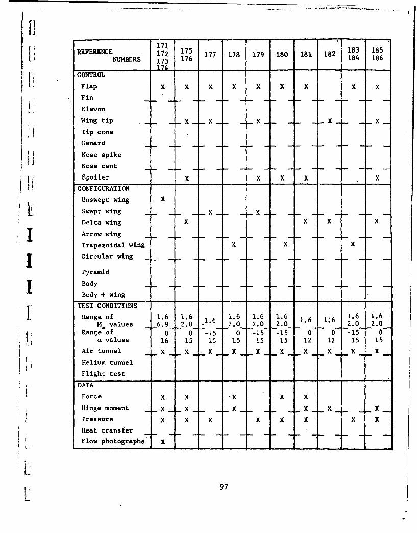
3.71[1 REFERENCE 172 175 177 178 179 180 181 182 183 185NUMBERS 173 176 184 186
CONTROL
--
17
Flap x x x X X X X X x
Fin
Elevon
Wing tip . X _ . XTip cone
Canard
Nose spike
Nose cant
SSpoiler X X X X XC ONF IGURAT ION
v Unswept wing XSSwept wing .. . .X _ _X . . . ...
Delta wing X X X X
Arrow wing
Trapezoidal wing X X X
I Circular wing
Pyramid
Body
Body -+- wing
TEST CONDITIONS
Range of 1.6 1.6 1.6 1.6 1.6 1.6 1.6 1.6 1.6M values 6.9 -- 2.0 1.6 2.0 2.0 2.0 2.0 2.0
Range of 0 0 -15 0 -15 -15 0 0-- -15-- 0a values 16 15 15 15 15 15 12 12 15 15
Air tunnel x K _ X _ X X X
Helium tunnel
Flight test
DATA
Force x x -x x xHinge moment X X . _ X X
Pressure x x x x x x x x
Heat transfer
Flow photographs K
97
L,

REFERENCENUMBERS 187 188 189 190 191 192 193 194 195 196
CONTROL
Flap X X X X X X X X X X
Fin X X
Elevon .
Wing tip X X
Tip cone
Canard X X
Nose spike
Nose cant X -
Spoiler X
CONFIGURATION
Unswept wing X X
Swept wing . •
Delta wing X X X X X X X X
Arrow wing
Trapezoidal wing
Circular wing .. .. . . .. .. .. .. . .
Pyramid
Body X
Body + wing X X X X X X
TEST CONDITIONS
Range of 2.4 2.9 2.0 1.4 1 2.0 1 2.9 1.7 3.0 -M. values 2.0 2.0 2.2 4.7 5.1 J
Range of 0 -4 0 -1 -10 0 -6 -3 -3 -2a values 10 90 90 27 10 29 18 90 16 12
Air tunnel, X _ X K X X X _ X X
Helium tunnel jFlight test
DATA
Force X X X X X X X X X XK
Hinge moment _ . X
Pressure X
Heat transfer
Flow photographs-I
92

REFERENCE 198 207NUMBER 197 200 201 202 203 204 205 206 208NUMBERS 19 ---99 208
SUCONTROLFlap X X X X X X X X X X
Fin _X x X
Elevon
Wing tip
Tip cone X X
Canard X
Nose spike
Nose cant X X X X
Spoiler
f Li CONFIGURATIONUnswept wing
Svept wing x xDelta wing X X X X X X X XArrow wing X X XTrapezoidal wing
Circular wing
Pyramid X X
Body X
Body + wing X X X X X XTEST CONDITIONSL Range of 1 1.6 6.7 8.1 6.7 6.9 6.9 3.1 2 1.5
M. values 18 9.6 18 .. 22 -_2.6
Range of 0 -5 -3 -25 27 0 0 -4 -5 0at values 12 25 12 50 56 12 30 24 30 6
Air tunnel X X X X X X X X X
Helium tunnel X XFlight test X
DATA
Force X X X X -X X X X XHinge moment
Pres sure
Heat transfer X
SFlow photographs
99
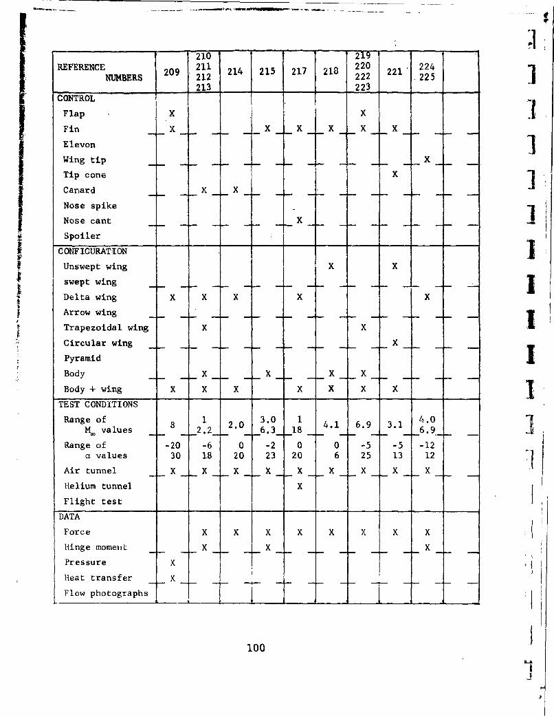
210 219REFERENCE 209 214 215 217 218 221' 224
NUMBERS 21 212 22212 225213 223
CONTROL I
Flap X X
Fin X X X X X X
Elevon IWing tip - X
Tip cone X 1
Canard K X
Nose spike I
Nose cant X
Spoiler TCONFIGURATION
Unswept wing X X
swept wing -... . . ... J-Delta wing X X X X X
Arrow wing
Trapezoidal wing X X
Circular wing X
Pyramid IBody X X X X
Body + wing X X X X X X ITEST CONDITIONS
Range of 8 2.0 3.0 1 4.1 6.9 3.1 4.0M. values 2.2 6.3 18 6.9
Range of -20 -6 0 -2 0 0 -5 -5 -12a values 30 18 20 23 20 6 25 13 12
Air tunnel X X X X X X X X X
Helium tunnel X
Flight test
DATA
Force X X X X X X X X
Hinge momeut X X X
Pressure X
Heat transfer X
Flow photographs T T
I100 -
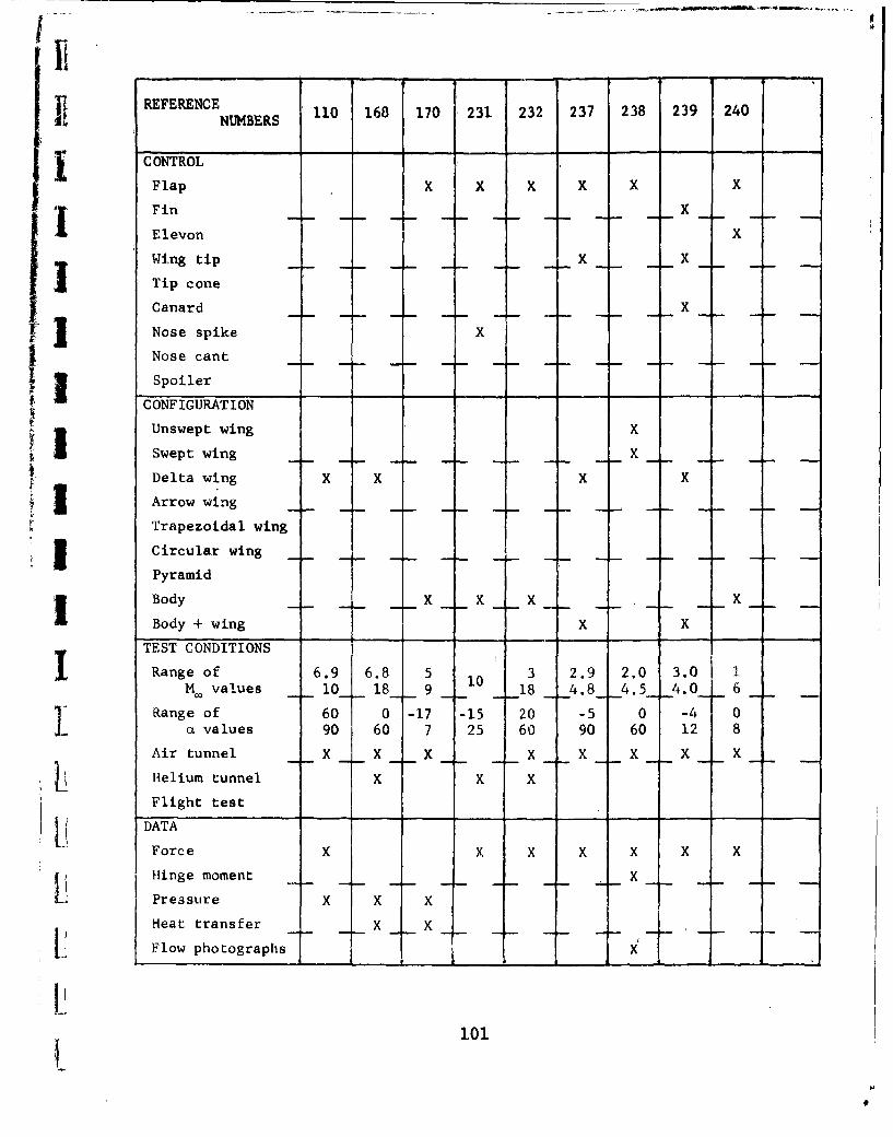
REFERENCE 0 168 170 231 232 237 238 239 240NUMBERS
CONTROL
Flap X X X X X X
Fin X
Elevon Xi Wing, tip .. . . . . X X . .
Tip cone
Canard I.. __X
Ns spike
Nose cant ... . . . . .
Spoiler
CONFIGURATION
Unswept wing X
Swept wing X
Delta wing X X X X
Arrow wing
Trapezoidal wing
3: Circular wing
Pyramid
Body X . X
Body + wing X XTEST CONDITIONSI
Range of 6.9 6.8 5 10 3 2.9 2.0 3.0 2M values 10__ 18__ 9 -- 18 __4.8_ 4.5 -- 4.0-_ 6
Range of 60 0 -17 -15 20 -5 0 -4 0a values 90 60 7 25 60 90 60 12 8
Air tunnel X X X X X X X X
Helium tunnel X X X
Flight test
DATA
Force X x X X X X X
Hinge moment x
Pressure X X X
Heat transfer x x _
Flow photograplhs --A x
101
N
9
4I
¶11ol.N1
'0 44 HO 1~E~fl ~0
II6 11C
-,4-
[ICA1 ..41 c ~ 0
9: ~ - C.4*H
U)')4).0, HS '1,14H if 00 3 4
LIo a~- 0 . .D
0 ~ HI
to -ýq o 0 IdI' -6 o.r
Ll~ 0 A l'I a ý.L 4.4 4-1001~4
~~in