ad-a271 736 iii11111 'lii iiiunlimited distribution i national defence … · ·...
TRANSCRIPT

AD-A271 736Iii11111 'lii iiiUNLIMITED DISTRIBUTION
I National Defence Deifense nationaleResearch and Bureau de rechercheDevelopment Branch et developpement
TECHNICAL COMMUNICATION 93/310TE ) T I CtOctober 1993
USER'S MANUAL FOR MAVPAT,
A MAVART3D TO PATRAN TRANSLATOR
C. J. Purcell
I hi~id,-tenthas been appsovedfor public relearse and ýale; its
Research Recherches pour laEstablishment DefenseAtlantic X \ Atlantique
Canadc! 93-96252

UNLIMITED DISTRIBUTION
National Defence D6fense nationaleIgewch and Bureau do rechercheDemlopment Branch et d6veloppement
* "USER'S MANUAL FOR MAVPAT,A MAVART3D TO PATRAN TRANSLATOR
C. J. Purcell
October 1993
Approved by P.R. Staal Distribution Approved by C.W. BrightHead I Underwater Acoustics Section
Director / Sonar Division
TECHNICAL COMMUNICATION 93/310
Defence Centre deResearch Recherches pour laEstablishment D6fenseAtlantic Atlantique
CanadI
" LI

Abstract
This communication describes how to use the computer program MAVPAT, Version 1.0,developed at Defence Research Establishment Atlantic (DREA) to translate MAVART3D anal-ysis results files to a form compatible with the finite element modelling program PATRAN.MAVART3D is a computer program used for finite element analysis of piezoelectric sonar trans-ducers. Once read by PATRAN, the translated MAVART3D analysis results can be displayedgraphically, and superimposed on images of the finite element model. This communication showshow to configure the PATRAN software so that finite element model generation, MAVART3Danalysis, data translation, and display of results can all be done within the PATRAN envi-ronment. The integrated operation of PATRAN, PATMAV, MAVART3D, and MAVPAT isillustrated with the worked example of the modal analysis of the shell of a barrel stave projec-tor. The example also shows how PATRAN Command Language can be used in the parametricdesign of a sonar transducer.
Resume
La prdsente communication ddcrit le mode d'utilisation de la version 1.0 du programme infor-matique MAVPAT, 6crit au Centre de recherches pour la defense Atlantique (CRDA), pourconvertir les fichiers de r6sultats d'analyse du MAVART3D en une forme compatible avec leprogramme PATRAN de moddlisation par dlments finis. MAVART3D est un programme infor-matique d'analyse par dl6ments finis de transducteurs de sonars pidzo-dlectriques. Une fois luspar PATRAN, les rdsultats convertis de l'analyse effectude par MAVART3D peuvent 6tre affichdsgraphiquement et superposes A des images du modles par dlments finis. La presente commu-nication montre comment configurer le logiciel PATRAN pour que la gdndration de modules Adlments finis, l'analyse par le programme MAVART3D, la conversion des donndes et l'affichagedes r6sultats puissent tous 6tre effectuds dans l'environnement PATRAN. L'exploitation int6grdede PATRAN, PATMAV, MAVAPT3D et MAVPAT est illustrde au moyen de l'example d'analysemodale de l'enveloppe d'un projecteur en douve de baril. L'exemple montre aussi comment leLANGAGE DE COMMANDE PATRAN (PCL) peut 6tre utilis6 dans la conception param6triqued'un transducteur de sonar.

Contents
Abstract ........... ..............................................
Table of Contents ........... ........................................ .ii
1 Introduction ................................................... 1
1.1 Organization of the Manual ........ .............................. 1
1.2 PATRAN, PATMAV, MAVART3D, and MAVPAT ................. 1
2 Software Configuration for Consecutive Operation .................... 2
2.0.1 MAVPAT User Input ............................. 5
2.0.2 MAVPAT Output Files ............................ 5
2.0.3 Displaying Results Files with PATRAN ................... 6
2.0.4 Modal Analysis Results ............................ 6
2.0.5 Animation of DRIV Results .......................... 6
2.0.6 Plotting Frequency Sweep Results ...................... 7
3 Software Configuration for Concurrent Operation ..................... 7
4 Example - Modal Analysis of Barrel Stave Shell ............................. 9
4.1 Display of Results of Barrel Stave Modal Analysis ...................... 15
5 Summary and Conclusions .................................. 17
5.1 Further Developments of MAVPAT ................................. 17
R eferences . . . . . . . . . . . . . . . . . . . . . . . . . . . . . . . . . . . . . . . . . . . . . 18
Appendix A: Command Procedures .............................. 19
Appendix B: MAVPAT Results Files .............................. 20
NTIS CRA.&; - .
I T. C ] '---J,,'T!fjc, Jio-,
..J .. .. . .. .. .......... .Di ,t i6 ;tbor: I
Avaji id [ icrDist

1 Introduction
The Transducer Group of the Defence Research Establishment Atlantic (DREA) designstransducers such as hydrophones and underwater sound projectors in support of the Estab-lishment's research programs in underwater acoustics. One of the most important design toolsavailable to the DREA Transducer Group is finite element analysis. Special purpose finite el-ement analysis codes, such as MAVART3D[1, 2], are used. MAVART3D is distinguished fromother finite element codes for mechanical engineering in that it can analyse the deformationsand vibrations of piezoelectric materials.
Because MAVART3D is strictly for analysis, and has no graphical display capabilities, arequirement exists for computer software to display the results of MAVART3D finite elementanalysis, and superimpose these results on images of the finite element models. The PATRAN[3]model generation software, from PDA Engineering, is used at DREA for creation of finite ele-ment models for MAVART3D and other analysis codes. PATRAN also has extensive supportfor the display of finite element analysis results, so it is the obvious choice for MAVART3Dresults display. Model output files from PATRAN are translated by the "forward translator",PATMAV[4], to a form ready for analysis by MAVART3D. After MAVART3D analysis is com-plete, the results must be translated to a form that is readable back into PATRAN. The programMAVPAT, described in this communication, was written to do this "reverse translation". Thecombination of PATRAN, PATMAV, MAVART3D, and MAVPAT permit model creation, anal-ysis, and results display, all within one software environment that will be useful for the designof sonar transducers.
1.1 Organization of the Manual
This document is organized into 5 sections followed by the list of references and appen-dicies. Section 1 provides an introduction and historical overview of the MAVPAT softwaredevelopment. Section 2 describes the software configuration for consecutive operation of thePATRAN, PATMAV, MAVART3D, and MAVPAT software. Section 3 describes the config-uration for concurrent operation where PATMAV, MAVART3D, and MAVPAT are run fromwithin the PATRAN environment. Section 4 presents an example illustrating the use of the PA-TRAN, PATMAV, MAVART3D, and MAVPAT software, and models a transducer componentwith PATRAN Command Language. Section 5 is a summary containing proposals for futuredevelopment of the MAVPAT software. Appendix A lists the command procedures used to in-voke file translation from within PATRAN. Appendix B describes the format of the results filesproduced by MAVPAT.
1.2 PATRAN, PATMAV, MAVART3D, and MAVPAT
PATRAN PLUS Version 2.5[3), a product of PDA Engineering, Costa Mesa, California, isan integrated set of computer programs for the creation of finite element models for mechanicalengineering. It also provides extensive support for the display of the results of finite elementanalysis. The models created with PATRAN are written to a file called the PATRAN Neutralfile. The program PATMAV, Version 1.014], was developed at Defence Research Establishment

Atlantic (DREA) to translate PATRAN Neutral files to a form ready for analysis by the pro-gram MAVART3D. MAVART3D Version 1.0[1, 2] is a finite element analysis program developedunder contract to DREA by Acres International Ltd., Niagara Falls, Ontario, during the period1990-91. MAVART3D is based on the program MAVART, developed for DREA by Canadianindustry in a series of research contracts during the period 1975-1988. The name MAVART is anacronym for Model for the Analysis of the Vibrations and Acoustic Radiation of Transducers.The purpose of MAVART is to analyze the performance of axisymmetric piezoelectric sonartransducers. The program MAVART3D extends the capabilities of MAVART to the analysis oftransducers that have no symmetry axes1.
MAVPAT, Version 1.0, was developed at DREA in 1991, to translate MAVART3D analysisresults files to a form ready for display by PATRAN. MAVPAT, like PATMAV and MAVART3D,is written in Fortran-77 and has been developed for use on Digital Equipment Corp. VAXcomputers using the VMS operating system. MAVPAT requires little user input, so that mostof this communication concerns file specifications and system configuration. Also, an exampleis presented in Section 4 showing how PATRAN, PATMAV, and MAVART3D can be used tocreate and analyze a finite element model of a transducer, and how MAVPAT and PATRAN canbe used to display the results. The model is built using PATRAN Cot imand Language (PCL) [5].The example illustrates a technique for model generation, called parametric modelling, where themodel generation is controlled by a small number of design parameters. This modelling methodis ideally suited for optimizing the performance of a transducer by varying some of the designparameters. The example shows how model preparation, Neutral file translation, MAVART3Dfinite element analysis, and display of results can all be accomplished within a single PATRANsession.
2 Software Configuration for Consecutive Operation
The following site specific VMS definitions permit the programs described in this sectionto be invoked simply by typing their names.
$ PATRAN:== @$1$dus2: [softpacs.patran]patran.run$ PATMAV: == run dreapacs: [mavart] patmav. exe$ MAVART3D:== run dreapacs: [mavart.mavart3d] mavart3d.exe$ MAVPAT:== run dreapacs: [mavart]mavpat.exe$ POSTSCRIPT: == run $1$dus2: [softpacs.patran.patran25.hardcopy] postscript .exe
Fig. 1 illustrates the relationships between the programs and some of the data files thatmake up the PATRAN-PATMAV-MAVART3D-MAVPAT software environment when they areused consecutively, i.e., each piece of software is run to task completion before the next programis invoked. In Fig. 1 the computer programs are indicated by circles; the data files by rectan-gles. The arrows indicate data-flow directions; the switches indicate optional data-flow paths.PATRAN reads and writes to over 20 different data files during its operations, Fig. 1 shows onlythe most commonly used ones.
'Acoustic radiation is not yet modelled by MAVART3D, it will be included in Version 2.0 of the softwarescheduled for delivery in 1993.
2

GRAPHICSTERMINAL PATRAN.SES VMS
EDITOR
PATRANDAT
PATRAINTAF PATRAN PATRANSES POSTSCRIPTPATRAN HRD
PS.PLT
PATRAN.OUT
WAVEFORMJDAT
LASERPRIN'TER
PATMAV
NIAV.DAT
xRESun.DAT
MATERL.DAT MAVART3D xSTRan.DAT
4
FOUDC.DAT
PLTnn.DAT
0-- DISPLACEME-.lT.D;7T'
IP-- VOLTAGEDAT
NSTRAINDAT
'NSTRESS.DAT MAVPAT
ESTRAKDAT
ESTRESSDAT :1 4 )
4 ADMITTANCEZAT
Figure 1: PATRAN-MAVART3D flowchart for consecutive operation.
3

In Fig. 1 PATRAN is shown being controlled from a graphics terminal. Problems with thegraphics, e.g., colour mapping, or image size, can be due to incorrect descriptions of terminalattributes. These are stored in the terminal attributes file PATRAN.TAF. The system managercan edit this file to modify the terminal description as required.
All user input to PATRAN is copied to the session file PATRAN.SES which, as indicatedin Fig. 1, can be modified by a text editor and used to control a new PATRAN session. Thiscapability is useful. It permits the user to exp-riment freely with different PATRAN modelbuilding techniques, knowing that if mistakes are made, the session can be reconstructed byexiting PATRAN; the unwanted modelling commands can be edited out of the session file, andthen the edited session file can be used to reconstruct the model. Also, the session file can berun in single step mode for debugging purposes.
At the end of a PATRAN session, PATRAN generates the file PATRAN.DAT which con-tains, in addition to the model geometry, the graphics parameters for such items as colours,windows, viewpoints, rotations, etc. This file can be read at startup of a subsequent PATRANsession to quickly restore a model for further work, without having to reprocess all the commandsin the previous session file.
As indicated in Fig. 1, hardcopy output of PATRAN graphics are written to the file PA-TRAN.HRD. This file can be translated into Postscript format using the PATRAN translatorprogram POSTSCRIPT[3]. The translated file, given the name PS.PLT, can be printed on aPostscript compatible colour or black and white printer.
The PATRAN Neutral file, containing the finite element model data, is PATRAN.OUT. It iscalled Neutral because the data it contains is the same regardless of computer system or graphicsterminal used in its creation. This is in contrast to the file PkTRAN.DAT, which is sensitive tothe type of graphics terminal used. After the PATRAN session is terminated, the PATRAN-to-MAVART3D translator, PATMAV[4], can be run. The highest numbered version of the Neutralfile PATRAN.OUT is read and translated to MAVART3D compatible form by PATMAV. Theuser is prompted for data needed by MAVART3D that cannot be obtained from the Neutralfile. The only other file accessed by PATMAV is indicated in Fig. 1 as WAVEFORM.DAT.,which describes the waveform of a transient excitation, an option used only if a MAVART3D"TRANsient" analysis is selected in PATMAV. PATMAV's output file, MAV.DAT, is ready foruse as the input data file for MAVART3D.
The user must provide MAVART3D with the input data file name (e.g., MAV.DAT). Theuser must also input a single character (substituted for the dummy prefix" x" in following filenames) which is used to identify an optional material data file, xMATERL.DAT, and whichforms an identifying prefix to label the output files. MAVART3D produces a number of outputfiles[1], some of which are shown in Fig. 1. Only the plot file with the name xPLTnn.DAT is usedby MAVPAT. The dummy suffix "nn" is a version number built into the file name. This namingconvention was added to the most recent versions of MAVART and MAVART3D to facilitateportability to other computer operating systems. The MAVART3D plot file is an unformatted
2file, with a file header containing all MAVART3D data array dimensions
2The array dimensions are stored in the file DREAPACS:[MAVART.MAVART3DJM3DSIZ.INC, used in thecompilation of MAVART3D.
4

2.0.1 MAVPAT User Input
The program MAVPAT prompts the user for the name of the MAVART3D plot file, e.g.,xPLTnn.DAT. MAVPAT checks for the existence of the selected plot file and prompts for a newselection if the selected file does not exist. MAVPAT reads the plot file header to obtain thedimensions of the plot file's data records. MAVPAT terminates with a fatal error message if
it has been compiled with insufficient data array dimensions. The message will indicate which
array dimension needs to be increased. A carriage return supplied in response to the query forthe plot file name terminates the program. The only other user input required by MAVPAT,
is the number of phases (animation frames) desired for animation of displacement and voltage
results from MAVART3D DRIV analysis[1] described in Section 2.0.5 below.
2.0.2 MAVPAT Output Files
MAVPAT rewrites the data in xPLTnn.DAT into a series of files in the format of PATRAN
results files[3]. The number of files written depends on the MAVART3D analysis type. MAVPAT
utilizes the VMS naming convention for its output files, i.e., they are identified by version
numbers. Table 1 gives the names and purposes of the data files produced by MAVPAT for
different MAVART3D analysis types.
The output files generated by MAVPAT are formatted (ASCII) files 3 that can be read by
ordinary text editors. PATRAN can read three types of results files: nodal, element, and X-Ydata. Nodal results files contain results computed at nodes, element results files contain resultscomputed at element centroids, and X-Y data files contain two columns, the independent anddependent variables, respectively, e.g., frequency and admittance. MAVPAT produces all threetypes of results file as indicated in Table 1. The generic format of these files is described in [3].Specific formats for the files listed in Table 1 are described in Appendix B.
3 PATRAN can also read unformatted (binary) results files, but to facilitate portability of results files across
computer systems, only formatted files are produced by MAVPAT.
Table 1: MAVPAT output files resulting from MAVART3D analysis.
FILE NAME TYPE FILE CONTENTS ANALYSIS TYPEDISPLACEMENT.DAT nodal nodal displacements STAT, EIGE. CAPA, DRIVVOLTAGE.DAT nodal voltage at PIEZO nodes STAT, EIGE. CAPA, DRIVNSTRAIN.DAT nodal strain at corner nodes STAT, CAPA. DRIVNSTRESS.DAT nodal stress at corner nodes STAT, CAPA, DRIVESTRAIN.DAT element strain at element centroids STAT, CAPA, DRIVESTRESS.DAT element stress at element centroids STAT, CAPA, DRIVADMITTANCE.DAT X-Y frequency sweep results CAPA, DRIV
5

2.0.3 Displaying Results Files with PATRAN
The PATRAN software provides a number of ways to present finite element analysis resultsgraphically. The displacements, voltages, stresses, strains, electric fields, and electric displace-ments can be visualized superimposed on images of the original model, using a variety of plottingtechniques including vector and tensor plots, and colour and line contour plots.
To display analysis results with PATRAN, the model's PHASE 2 data (element data) mustbe in PATRAN's current ACTIVE SET[3]. If the model data are not already present, there areseveral ways to load a previously generated model. The GO command can be issued at PATRANstartup to retrieve the file PATRAN.DAT from the previous session. PATRAN could also beinstructed to read in the model's Neutral File, using the INTERFACE, NEUTRAL. INPUT MODELmenu selections. If these two files are not available, it is also possible to rebuild the model usinga copy of the model's session file. It is usually necessary to edit the session file, e.g., removingthe final STOP command. To save time, the SET, GRAPHICS, OFF command can be added atthe beginning of the session file to suppress plotting of all model generation steps. Then startPATRAN, instructing it with the SES command to start with the edited session file, or load thesession file with the READFILE command. When the model is complete, graphics display can beenabled using the SET, GRAPHICS, ON command.
At this point, with the model loaded into PATRAN, there are a number of ways to instructPATRAN to load results data depending on the type of data (nodal, element, or X-Y), and thetype of results display required. A full description of all results display techniques is beyond thescope of this communication, instead, see Chapter 27 of [3]. Section 4.1 presents an example ofthe commands to select one type of results display.
2.0.4 Modal Analysis Results
The mode shape results from a MAVART3D EIGE analysis are written to a sequenceof files xPLTnn.DAT, with one plot file created for each resonance frequency found. ThusMAVPAT will have to be run on each file xPLTnn.DAT in turn in order for PATRAN to beable to display the mode shapes corresponding to all the eigenfrequencies. The mode numberand resonance frequency as found by MAVART3D are passed by MAVPAT to the file DIS-PLACMENT.DAT, and unless instructed otherwise with the SET, LABD, OFF command. PA-TRAN will include these numbers as part of the title of deformed geometry plots. Animationsof real valued displacement results from EIGE or CAPA analysis can be generated with theRESULTS, DISPLACEMENT, ANIMATE commands.
2.0.5 Animation of DRIV Results
For MAVART3D analysis type DRIV, the solutions (displacements and voltages at nodes)are complex-valued 4. PATRAN cannot interpret complex displacements directly, so these casesare handled by MAVPAT differently from STAT, EIGE, and CAPA results, which are real val-ued. When MAVPAT detects that a DIUV analysis has been completed, it prompts for the
4MAVART3D stress and strain results are real-valued magnitudes only.
6

number of output phases. The displacements and voltages of the model at the selected numberof instants during one drive cycle are computed and written to a set of DISPLACEMENT.DATand VOLTAGE.DAT files, one for each phase value. When these are later all read into PA-TRAN using e.g., the RUN, ANI!.JLE command, it is possible to animate the complex-valuedDRIV results. Different parts ,, the model can be shown moving with different relative phases,something that would noL ue possible with purely real displacement data. This type of motionis typical of materials that have internal damping.
2.0.6 1"otting Frequency Sweep Results
PATRAN also has a facility for making X-Y plots of data using its P/PLOT module.MAVART3D frequency sweep results(l] such as admittance and impedance. are written by MAV-PAT to the file ADMITTANCE.DAT, described in Appendix B, Table 10. This file can be readby the PATRAN P/PLOT module and be used to plot these results versus frequency. Whena frequency sweep is done in a MAVART3D CAPA or DRIV analysis, a series of sequentiallynumbered plot files xPLTnn.DAT are created. The lowest numbered file (typically nn = 01) willcontain the results from the first frequency in the sweep. The next file in the series (typicallynn = 02) will contain the results of the next frequency in the sweep concatenated with theresults of the previous plot file, and so on. Typically P/PLOT should be instructed to read anddisplay the plot file with the highest value for "nn", since that file contains the frequency sweepresults for all frequencies in the sweep. The plot files with lower numbers are also valuable, theycontain, e.g., the displacement, stress, strain and directivity results for each frequency.
3 Software Configuration for Concurrent Operation
The programs PATRAN, PATMAV. MAVART3D, and MAVPAT can be run in a concurrentmode, in which all user input to PATMAV. MAVART3D, and MAVPAT. is entered from withinthe PATRAN environment. This software configuration is depicted in Fig. 2. In order forPATMAV. MAVART3D, and MAVPAT to be accessible from PATRAN it is necessary for thefile PATRAN.IFC, indicated in Fig. 2, to be modified by the system manager, so that the firstthree lines of the file 5 are as follows:
MAVART3D(0dreapacs: [mavart] patmav. com©dreapacs: [mavart] mavpat .com
The first line provides the name MAVART3D to the PATRAN INTERFACE command menui tobe used as a label. The following two lines specify command procedures that are invoked whenthe TO MAVART3D, and FROM MAVART3D options in the PATRAN INTERFACE mentu are selected.The Digital Command Language (DCL) procedures PATMAV.COM and MAVPAT.COM arelisted in Appendix A.
5These lines are site specific. Putting them al, the top of the file results in MAVART3D being the second pickin the PATRAN interface menu, with Neutral file creation being the default first menu item.
7

GraplucsTerm... PATRANSES VIS TEXT
EDITOR
PATRAYDAT
PATRAYIFC PATRAN PATRAN.SES POSTSCRH'TPATRANTAF PATRAN HRD
PS PLT
PATMAV-COM MAVPAT.COM
LASERPUNTER
PATRANOUT
PATMAV NIAVPAT
NfAV DAT
-MATERLMAT DISPLACEMENT VAT
VOLTAGE.DAT
NSTRAPi.DAT
NIAVART3D ESTRAINDAT
ESTRESS.DAT
I
NSTRESSDAT
TAD,%IrrrA.NCE.DA J ý
PLT...DAT
Figure 2: PATRAN-MAVART3D flowchart for concurrent operation.
8
The command procedure PATMAV.COM indicated in Fig. 2 runs the program PATMAVusing data input from the terminal, followed by a submission of tLe MAVART3D job to a batchqueue, typically one intended for large jobs. Control is then returned to PATRAN so that theuser can continue working with PATRAN, while MAVART3D runs in the queue. The user isinformed by a message printed to the terminal when the MAVART3D analysis is finished. Atthat point the FROM MAVART3D option of the PATRAN INTERFACE command can be selected.This will invoke the command procedure MAVPAT.COM which runs the program MAVPATusing data input from the terminal. Once MAVPAT translation is complete, control is returnedto PATRAN, and the PATRAN RESULTS command can be selected to display the analysis resultsusing the files created by MAVPAT, and listed in Table 1.
4 Example - Modal Analysis of Barrel Stave Shell
* In this section, an example is presented that illustrates the use of PATRAN, PATMAV,MAVART3D, and MAVPAT. The example uses PCL, which is a programming language thatsupports PATRAN. PCL is useful for doing parametric design studies of transducers wherenumerous models must be constructed with different model parameters.
Z
2A
8 Slots 0.8 width @45 deg
200. R. of C. 3 18.5
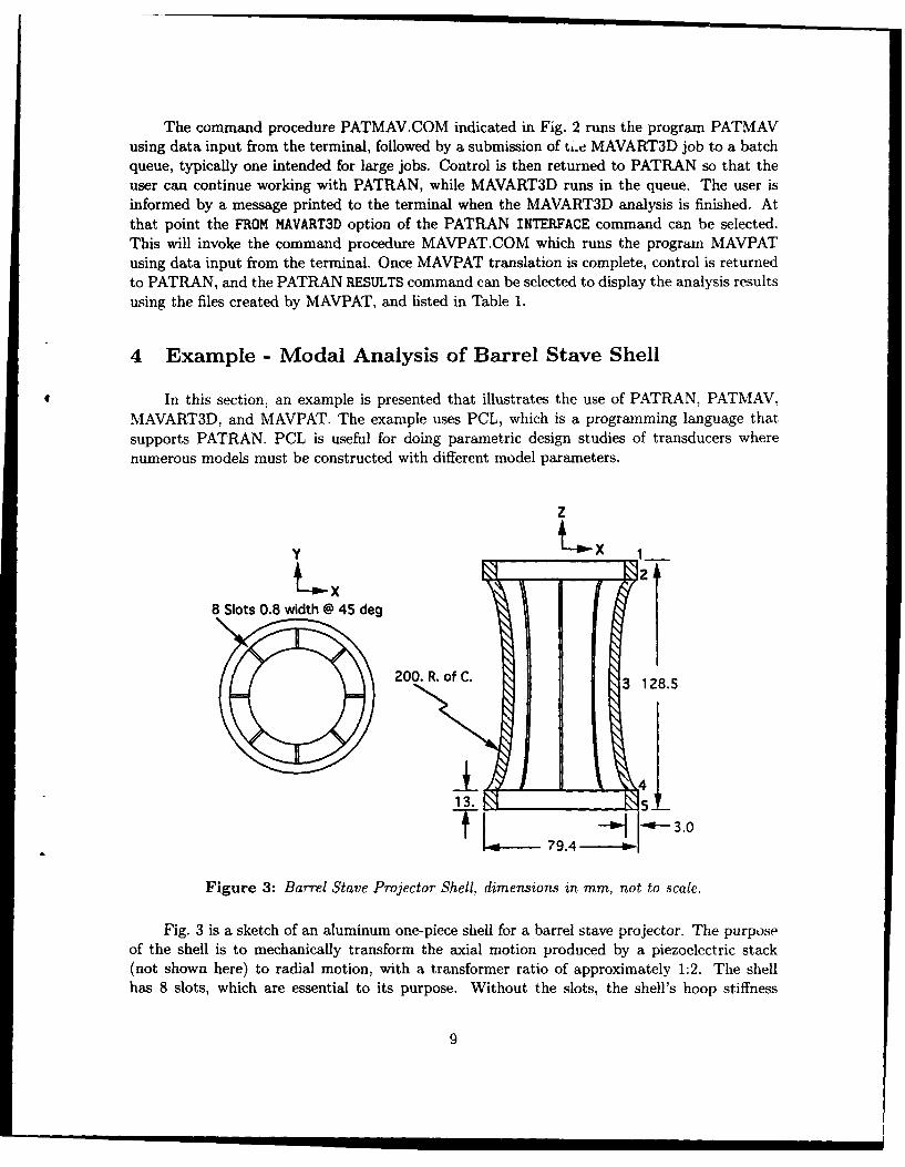
I ~4 5.Figure 3: Barrel Stave Projector Shell, dimensions in mm, not to scale.
Fig. 3 is a sketch of an aluminum one-piece shell for a barrel stave projector. The purposeof the shell is to mechanically transform the axial motion produced by a piezoelectric stack(not shown here) to radial motion, with a transformer ratio of approximately 1:2. The shellhas 8 slots, which are essential to its purpose, Without the slots, the shell's hoop stiffness
9

would be too high and the resultant transformer ratio would be uselessly small. Jones[6] usedthe axisymmetric finite element program MAVART[7, 8] to make preliminary designs of theshell by modelling the effect of the slots as a decrease in the tangential component of stiffness.The required modification to the material properties had to be determined experimentally, bybuilding projectors, measuring their in-air admittance, and comparing this to the MAVARTpredictions. With the introduction of MAVART3D, it is now possible to analyze the in-airperformance of the complete projector, with slots, using just handbook values for the materialproperties. To keep the example simple, a modal analysis of only the shell will be performed topredict the eigenfrequencies and mode shapes in vacuum.
To take advantage of PATRAN's capability of parametric modelling, the dimensions re-quired to specify the model are stored in PCL variables in a session file. Therefore, the mod-elling process begins with examination of a drawing like Fig. 3 and a determination of whatdimensions are both necessary and sufficient to completely define the model geometry. All otherdimensions are derived from these by defining functional relationships in PCL.
The session file can be written entirely with a text editor, but it is often efficient to crea'ea first draft of the session file interactively, with PATRAN, and later, add the PCL commandsto the session file with an editor.
Table 2 contains a PATRAN session file that has been edited and annotated, and, whenprocessed by PATRAN, will generate a finite element model of a barrel stave shell suitable for amodal analysis. The line numbers in the left-most column and the comments in the right-mostcolumn are :rot present in the session file, they are for reference only. Only essential commandsare shown in Table 2, some preliminary commands have been deleted, and other commands toenhance the graphics, such as setting window size and view-point, etc., would normally also beused.
Line 1 of Table 2 is a comment line, these may be inserted anywhere in a PATRAN sessionfile and begin with the $ symbol. Comments may also be inserted as in Line 2 where thedimensions are noted. Any consistent system of units can be used in creating PATRAN models.Line 2 defines the smallest non-zero distance.
The PMAT (Properties of Materials) command in Line 3, assigns a material identifier (mid)= 1, and defines the isotropy, stiffness, Poisson ratio, and density of the shell material. Theseare properties typical of the Aluminum alloy 6061-T6.
The first PCL command in the session is Line 4. PCL commands begin with an exclamationmark, and can be mixed throughout the session file's regular PATRAN commands. Lines 4-6allocate storage for the PCL variables. Lines 7-14 specify values for the essential PCL variables.These are the data from which the entire model is generated. Lines 16-20 define derived variablesin terms of the essential variables. When a PCL variable or expression is to be referenced by aPATRAN command, it is enclosed by backquotes as in Line 22.
Lines 22-27 define Grids, which are construction points used to aid in the construction oflines. The Grid points numbered 1-5 are indicated in Fig 3. The Grids numbered 6-10 are madeby translating Grids 1-5 a distance equal to the thickness of the shell, in Line 27. Lines 28-35create straight lines and circular arcs that define the cross-sectional shape of the shell.
10

Table 2: Session file for Shell Model
Line PATRAN and PCL Commands Comment1 $ MODAL ANALYSIS BARREL STAVE SHELL a PATRAN comment2 SET,TOLERANCE, 1.OE-5 /* meters */ smallest distance3 PMAT, 1,ISO,6.9E10,,.33,2700 material properties4 ' GLOBAL REAL Radius,zO,zl,w,s,dl essential variables5 ! GLOBAL INTEGER nstave6 ! GLOBAL REAL r0,rl,z,x,staveangle,slotangle derived variables7 I nstave = 8 number of staves8 I Radius = 0.2 radius of curvature9 ' zO = 0.1285 total height10 I z1 = 0.0130 height of flanges11 ' dO = 0.0665 o.d. at mid-point12 ! dl = 0.0794 o.d. of top (or bottom)13 ! w = 3.OE-3 wall thickness14 I s = 8.OE-4 slot width15 $ Next compute derived dimensions16 I rO =0.5*dO radius at mid point17 1 z = 0.5*(zO-2.0*zl) half height of slot18 1 x = sqrt(Radius*Radius-z*z) c. of curvature to shell19 I slotangle = 0.5*s*180.0/(rO*3.1415926) half angular slot width20 ' staveangle = 360.0/nstave-2.0*slotangle angular stave width21 $ Main body of PATRAN commands start22 GRID,1,, 'rO+Radius-x', 0.0, 'zO/2.0' define grid points23 GRID,2,,'rO+Radius-x', 0.0, 'z' topof slot24 GRID,3,,'r0', 0.0, 0.0 shell mid-point25 GRID,4,,X2, 0.0, '-z' bottom of slot26 GRID,5,,X2, 0.0, '-zO/2.0' bottom of shell27 GRID,6TI0,TRANS, '-w'/0.0/0.0,lT5 make grids on inside28 LINE,1,2GRID,,1,2 define lines29 LINE,2,ARC3,,2/3/430 LINE,3,2GRID,,4,531 LINE,4T6,TRANSLATE,'-w'/0.0/0.0,IT332 LINE,7,2GRID,,1,633 LINE,8,2GRID,,2,734 LINE,9,2GRID,,4,935 LINE,10,2GRID,,5,1036 PATCH,1,EDGE, ,2/9/5/8 define patches37 PATCH,2,EDGE,,1/8/4/738 PATCH,3,EDGE, ,3/10/6/9
11

Line POL or PATRAN Command Comment39 HPAT,1,ARC, define hyperpatches;
0/0/0/0/0/1/' staveangle' / 'slotangle' ,Pi40 HPAT,2T'nstave' ,ROTATE,
0/0/0/0/0/1/'360. 0/nstave', 141 HPAT,'nstave+l',ARC,
0/0/0/0/0/1/' staveangle'I' slotangle' ,P242 HPAT, 'nstave+2'T' 2*nstave' PROTATE,
0/O/O/0/0/1/'360. 0/nstave' ,'nstave+l'
43 HPAT, '2*nstave+1' .ARC,0/0/0/0/0/1/' staveangle' / 'slotangle' ,P3
44 HPAT. '2*nstave+2'T'3*nstave' ,ROTATE,0/0/0/0/0/1/'360. 0/nstave','2*nstave+l'
45 HPAT, '3.O*nstave+l' ,ARC,0/0/0/0/0/1/' 2.0*slotangle'I' -slotangle' ,P2
46 HPAT, '2+3*nstave'T'4*nstave' ,ROTATE,0/0/0/0/0/1/ '360. 0/nstave' ,'3*nstave.I-'
47 HPAT, '1+4*nstave' ,ARC,O/O/0/O/O/1/'2.0*slotangle'/'-.slotangle' ,P3
48 KPAT, '2+4*nstave'T' 5*nstave' ,ROTATE,0/0/0/0/0/1/'360.0/nstave' ,'1+4*nstave'
49 MESH,H1T#,HEX/8, ISO, 0.01,-i create finite elements50 EQUIVALENCE equivalence all51 N duplicate nodes52 253 154 Y55 756 157 158 RENUMBER renumber everything59 360 161 462 NEUTRAL create the Neutral file63 164 165 EIGEN ANALYSIS 8 SLOTTED SHELL title66 Y67 Y68 2 All done
12

Lines 36-38 create patches (surfaces) from the lines and arcs. The patches are sweptabout the Z axis to form hyperpatches (volumes) in Lines 39-48. Line 39 also illustratesthat a PATRAN command line can be continued onto the following line if the last characteris a comma.
The finite element mesh is created with the single MESH command on Line 49. Hex-ahedral elements with 8 nodes are selected, with side length of 0.01m, and containingmaterial with mid = 1, as defined in Line 3. A more general approach would be to makethe element side length a fraction of some shell dimension.
In Line 50, the EQUIVALENCE command equivalences nodes whose separation is lessthan the tolerance set in Line 2. This is an important step, it attaches all the elementsof the model together into a single piece of material. Note that if the tolerance wereset larger than the slot width, the slots would be fused together, which would not bedesirable. Therefore, when writing a more robust version of this session file, the toleranceshould be set to be less than some fraction of the slot width.
The EQUIVALENCE operation may delete some nodes, which will disrupt the nodenumbering sequence of the remaining nodes. The RENUMBER command on Line 58 is ahouse-cleaning operation that sequentially renumbers the nodes6.
At this stage it would be appropriate to set the boundary conditions, however in thisexample the modes of a completely unconstrained shell are desired, so no boundary condi-tions are needed. Since nothing prevents the shell from undergoing rigid body translationsor rotations MAVART3D may find the 6 rigid body modes7 unless the eigenvalue searchstarting frequency is set suitably high, e.g., higher than the lowest vibrational mode. Thismay require several trials, since the lowest frequency is not known a priori. Thus, thefirst real mode can be expected to be number 7.
Tb- PATRAN Neutral file containing all the model data is written out in Lines 62-67,and after this the model is ready for PATMAV translation.
In the consecutive mode, at this point, the PATRAN session can be terminated,followed by an invocation of PATMAV. PATMAV will prompt for all data required toperform the translation. To produce the results presented in Section 4.1, the user suppliedinputs to PATMAV were all default values (invoked by carriage returns) with the exceptionof the following: (1) the selection of EIGE analysis, (2) the selection of the search node(node 1, which is at the end of the shell, was used), (3) search degree of freedom (Z), and(4) the frequency range for the search (1200-5000 Hz).
In the concurrent mode of operation, PATMAV translation can be invoked with theINTERFACE, TO MAVART3D commands in PATRAN. As explained in Section 3, the DCLprocedures in Appendix A will then be executed. They, in turn, will run PATMAV, andprompt the user for input. When the MAVART3D analysis is complete, as indicated by a
6 Node and element numbering can have an impact on the cpu time of finite element solvers, so PATRANprovides the OPTIMIZE command, not used here, which allows users to renumber entities according to variousoptimization schemes.
7This results in MAVART3D terminating with an error message that a negative eigenvalue has been found.
13

/ I
MIvEIE]IDT-
S 11.1 l1-W1IIII••, • lJ 113W -IEIif 11 I
_________]_-III WDIDLI 11E1I
Figure 4: Finite element model of barrel stave shell
message from the batch processor, the PATRAN commands INTERFACE, FROM MAVART3D,can be selected and to run MAVPAT under the control of the DCL procedure MAV-PAT.COM. The user will be prompted for MAVPAT input, and when MAVPAT filetranslation is complete, control is returned to PATRAN. The RESULTS command can begiven, and then the translated filh • can be displayed.
A drawing of the model created by the session of Table 2 is shown in Fig. 4. ThePATRAN command: SET, SHRINK, . 1, has been used to draw the elements 10% smallerthan their true size, to delineate them better. As a quick check on the fidelity of the model,the mass of the model was computed using a density of 2700kg/mr3 and the PATRANcommand: SHOW, MASSPROP, 2700.0. The result was 220.2 gms, which agrees well withthe measured mass (220.19 gms) of the actual shell from which the dimensions for themodel were taken. The model includes the full shell, but for many types of finite elementanalysis only a fraction of the shell (e.g. as little as 1/(2 nstave) of the total) wouldneed to be modelled. The full shell has to be modelled if all vibrational modes includingtorsional vibrations are to be studied.
The advantage of using PCL is best seen by considering how easy it is to change themodel, e.g., to change the number of staves. This changes the number of hyperpatchesrequired, and leads to a completely different finite element mesh. Changing the numberof staves can be done simply by changing the single variable nstave on Line 7 of Table 2
14

and running the modified session file through PATRAN. The PCL routine creates therequired number of hyperpatches, and automatically fills them with elements. The entirechange can be done in a few minutes. This is in sharp contrast to a model built by strictlymenu driven grid generation software, such as LAPCAD[9], where a change such as thiswould require the manual re-entry of the entire model, a process that could take manyhours, depending on the size and complexity of the model.
It is possible to allow the parametric design process to be controlled interactively, byusing PCL commands to query the user for the design parameters, such as the number ofstaves. This technique would be useful for creating a "turnkey" design environment for aparticular sonar transducer, which could be used by someone with only modest experiencewith PATRAN and the finite element method.
In this example, the model geometry was defined using just a handful of PCL code.At some stages in building a more complex model, it may not be so easy to anticipatethe values certain PATRAN parameters may assume, e.g., the index of a particular node,or the number of elements in a particular hyperpatch, and yet those parameters may beuseful for building the rest of the model. It may be convenient to treat such cases by usingPCL commands to interrogate the PATRAN database, and read the required parameters,rather than try to define them directly using PCL commands as has been done above. Forexample, the hyperpatch indexing in Lines 39-48 of Table 2 could have been somewhatsimplified by using PCL database commands to determine the current highest numberedhyperpatch.
4.1 Display of Results of Barrel Stave Modal Analysis
In this section, some of the results of the MAVART3D modal analysis of the barrelstave shell model are presented. Hidden line images of the 4 lowest frequency mode shapes(modes 8,10,11, and 13), are shown in Fig. 5. Note that the mode with lowest frequency isnot the axially symmetric breathing mode used in the normal operation of the barrel staveprojector, but rather a circumferential ovalization mode. When displayed by PATRAN ona suitable workstation, images like these can be viewed from any direction, and animated.
To make the drawings in Fig. 5, MAVPAT was used to translate the MAVART3Doutput plot files to PATRAN results file format. Then the following sequence of commandswas input to PATHAN:
PATRAN PROMPT USER RESPONSEMODE? 1 (RESULTS)RESULTS TYPE? 2 (EXTERNAL DATA)RESULTS? 1 (DEFORMED SHAPE)INPUT NAME OF DISPLACEMENT FILE: DISPLACEMENT.DAT;nn
15

MODE S, 1264.1 HZ MODE 10, 2201.9 HZ
I L
MODE 11, 2419.2 HZ MODE 13,2536.9 Hz
Figure 5: Mode shapes of lowest 4• modes of barrel stave shell as predicted by MAVART3D.
The version number "un" in the last of the preceding commands refers to one of theDISPLACEMENT.DAT files of which there is one for each eigenfrequency. The preced-ing command sequence was repeated for each of the mode shapes shown in Fig. 5. Thefrequencies of the predicted modes shown in Fig. 5 will be checked by performing experi-mental modal analysis on actual shells, and this verification will be reported elsewhere.
In addition to the 6 rigid body modes, with zero frequency, there are other missingmodes (7, 9, 12) with respect to those shown in Fig. 5. These are probably degeneratemodes. For example, additional MAVART3D EIGE analyses with different search nodesand search degrees of freedom, established that modes 7 and 8 have the same eigenfre-quency, but correspond to different eigenvectors, i.e., modes 7 and 8 differ in shape, butonly by a rotation about the Z axis.
16

5 Summary and Conclusions
MAVPAT Version 1.0 completes the set of software tools required for effective use ofthe finite element code MAVART3D Version 1.0. It is now possible, using a graphics termi-nal or workstation and PATRAN, PATMAV, MAVART3D, and MAVPAT, to create andanalyze fully three-dimensional finite element models of piezoelectric transducers, loadedwith static forces, undergoing free oscillations, or being driven by complex valued charge,voltage, temperature, force, or displacement excitations in vacuum. All MAVART3D el-ements, material properties, and boundary conditions are supported. The translation ofdata files, invocation of MAVART3D, and the display of results is fully integrated withinthe PATRAN system. The PATRAN-generated colour images of MAVART3D results canbe made easy to interpret, and are esthetically appealing. The complete software sys-tem, consisting of PATRAN, PATMAV, MAVART3D, and MAVPAT, is a major advancein transducer modelling capability that should make a substantial contribution to theproductivity of those who use this software.
From the user's point of view, the operation of MAVPAT is simple, so that most ofthis document has concerned itself with system configuration and with the introductionof the concept of parametric modelling. This technique consists of describing a finite ele-ment model by mathematical relationships dependent upon a set of essential parameters,from which the model generation software can build a complete finite element mesh au-tormaticllvy The parameters in the example presented could easily be modified to builda series of models that would be valuable for optimizing a barrel stave projector design.This technique promises to have a major impact on the way finite element analysis oftransducers is done at DREA in the future.
5.1 Further Developments of MAVPAT
Because PATRAN can create and display results from two dimensional models, itwould be desirable to add support for the axisymmetric MAVART analysis to both PAT-MAV and MAVPAT. MAVART3D Version 2.0 is expected to be delivered in 1993. Itwill have the capability to model acoustic radiation using the boundary element method.It will be desirable to make modifications to both PATMAV and MAVPAT to supportradiation modelling.
17

References
1. E. Skiba. MAVART3" User's Manual. Contractor Report CR/91/466/U, DefenceResearch Establishment Atlantic, Dartmouth, N.S., Canada, 1992.
2. E. Skiba and G. W. McMahon. MAVART3D Theoretical Manual. Contractor ReportCR/91/466/T, Defence Research Establishment Atlantic, Dartmouth, N.S., Canada,1992.
3. PDA Engineering, Costa Mesa, California. PATRAN Plus User Manual, 1988.
4. C. J. Purcell. User's Guide to PATMAV, a PATRAN to MAVART3D Translator. Tech-nical Communication 92/316, Defence Research Establishment Atlantic, Dartmouth.N.S., Canada, 1992.
5. PDA Engineering, Costa Mesa, California. PATRAN Command Language (PCL)Guide, 1990.
6. D. F. Jones, Defence Research Establishment Atlantic. Private Communication, July1992.
7. E. L. Skiba and G. W. McMahon. User's Manual for Program MAVART. TechnicalMemorandum 91/201, Defence Research Establishment Atlantic, Dartmouth, N.S.,Canada, 1991.
8. E. L. Skiba. Theoretical Manual for Program MAVART. Contractor ReportCR/87/442, Defence Research Establishment Atlantic, Dartmouth, N.S., Canada,1987.
9. G. M. Lundgren. LapCAD, A Finite Element Modeller, User's Manual, MacintoshVersion. LapCAD Engineering, Chula Vista, California, 1989.
18

Appendix A: Command Procedures
The command procedures PATMAV.COM and MAVPAT.COM, (and the subpro-grams BATCH.COM and M3D.COM) that are invoked by selecting the PATRAN com-mand INTERFACE, followed by TO MAVART3D, are as follows:
$! Command procedure 'patmav.com'$! This procedure invokes PATRAN to MAVART3D translation from within$! PATRAN, and submits a batch job to run MAVART3D in a queue. The$! next line identifies the current user directory and defines a$! symbol for it that can be passed to the following commands.$ defdir==f$environment("default")$ run dreapacs:[mavart)patmav.exe$ Cdreapacs:[mavart]batch dreapacs:(mavart]m3d 'defdir'$ exit$!************************************************************4**********$1 Command procedure 'batch.com', usage: Q batch pl p2
$! This procedure submits the command file specified by 'p1'$! to a batch queue. The parameter 'p2' is the default directory to$! be used by command file 'p1' for getting data and writing results.$ submit/queue=sys$big-batch/notify/noprinter/parameters='p2' 'p1'$ exit$1***********************************************************************
$! Command procedure 'm3d.com', usage: Q m3d pl$! The parameter pl is the default directory. This procedure runs$! mavart3d in the directory as set below. This procedure is invoked$! with the command procedure 'batch.com'.$ set default 'p1'$ run dreapacs:[mavart.mavart3d]mavart3d.exeVAX1xmay. dat$ exit$!***********************************************************************$! Command procedure mavpat.com, usage: @ mavpat.com$ dir/size/since=today *plt*.dat$! The following line establishes that the input for the following$! run command will be the original input stream, usually the terminal.$ define/user.mode sys$input sys$command$ run dreapacs:(mavart]mavpat.exe$ exit
19

Appendix B: MAVPAT Results File Contents
Table BI: Format for nodal displacements file DISPLACEMENT.DAT
Record # Contents Format1 Title (from MAVART3D Data Card 1) (80A1)2 NN, MAXN, DMAX, NMAX, 3 (219, E15.6, 219)3 Date and Time (80A1)4 "Displacements at nodes" (80A1)5 to NN+4 ID, (DATA(J), J = 1, 3) (18, (3E13.7))
NN is the number of nodes, MAXN is the highest node identifier, DMAX is the maximumabsolute displacement, NMAX is the node where the max displacement occurs, DATA(j),(j = 1, 3) are X,Y,Z displacements of the nodes of all elements. For EIGE analysis, themode number and resonance frequency also appear in Record 4. For DRIV analysis. thephase (radians) at which the displacements have been calc-lated appears in Record 4instead.
Table B2: Format for nodal voltage file VOLT4GE.DAT
Record # Contents Format1 Title (80A1)2 NN, MAXN, DMAX, NMAX, 1 (219, E15.6, 219)3 Date and Time (80A1)4 "Nodal Voltages" (80A1)5 to NN+4 ID, DATA (18, (5E13.7))
NN is the number of nodes, MAXN is the highest node identifier, DMAX is the maximumabsolute voltage, NMAX is the node where the max voltage occurs, DATA is the voltageat PIEZO nodes. For EIGE analysis, the mode number and resonance frequency alsoappear in Record 4. For DRIV analysis, the phase (radians) at which the voltages havebeen calculated appears in Record 4 instead.
20

Table B3: Format for nodal strain file NSTRAIN.DAT
Record # Contents Format1 Title (80A1)2 NN, MAXN, 0, 0, 9 (219, E15.6, 219)3 Date and Time (80A1)4 "Strain at corner nodes" (80A1)5 to NN+4 ID, (DATA(J), J = 1, 9) (18, (3E13.7))
NN is the number of nodes, MAXN is the highest node identifier, DATA(j). (j 1.9) arethe 6 components of strain, followed by the 3 components of electric field at the cornernodes of all elements. The electric field values will be non-zero only at PIEZO nodes.
Table B4: Format for nodal stress file NSTRESS.DAT
Record # Contents Format1 Title (80A1)2 NN, MAXN, 0, 0, 9 (219, E15.6, 219)3 Date and Time (80A1)4 "Stress at corner nodes" (8OA1)5 to NN+4 ID, (DATA(J), J = 1, 9) (18, (3E13.7))
NN is the number of nodes, MAXN is the highest node identifier, DATA(j), (j = 1. 9)are the 6 components of stress, followed by the 3 components of electric displacement atthe corner nodes of all elements. The electric displacement values will be non-zero onlyat PIEZO nodes.
21

Table B5: Format for element stratn file ESTRAIN. DAT
Record # Contents Format1 Title (80A1)2 9 (15)3 Subtitlel (80A1)4 Subtitle2 (80A1)5 to NN+4 ID, NSHAPE, (DATA(J), J=1, 9) (218,/,(6E13.7))
NN is the number of elements, ID is the element identifier, NSHAPE is the element shapecode (BAR = 2, TRIANGLE = 3, QUADRILATERAL = 4, TETRAHEDRON = 5.WEDGE = 7, HEX = 8), DATA(j), (j = 1, 9) are the 6 components of strain, followedby the 3 components of electric field at the corner nodes of all elements. The electric fieldvalues will be non-zero only at PIEZO nodes.
Table B6: Format for element stress file ESTRESS.DAT
Record # Contents Format1 Title (80A1)2 9 (15)3 Subtitlel (80A1)4 Subtitle2 (80A1)5 to NN+4 ID, NSHAPE, (DATA(J), J=l, 9) (218,/,(6E13.7))
NN is the number of elements, ID is the element identifier, NSHAPE is the element shapecode (BAR = 2, TRIANGLE = 3, QUADRILATERAL = 4, TETRAHEDRON = 5.WEDGE = 7, HEX = 8), DATA(j), (j = 1, 9) are the 6 components of stress. followedby the 3 components of electric displacement at the corner nodes of all elements. Theelectric displacement values will be non-zero only at PIEZO nodes.
22

Table B7: Format for frequency sweep results file ADMITTANCE.DAT
Record # Contents Format1 "XDATA", Title, "frequencies (Hz)" (A5,2A40)2 TO 1 + N FREQ (*)2 + N "END" (A3)3 + N "YDATA", Title, "conductance (mho)" (A5,2A40)4 + N TO 3 + 2 * N DATA (*)4 + 2 * N "END" (A3)5 + 2 * N "YDATA", Title, "susceptance (mho)" (A5,2A40)6+2*NTO5+3*N DATA (*)6 + 3 * N "END" (A3)7 + 3 * N "YDATA", Title, "resistance (ohm)" (A5,2A40)8+3*NTO7+4*N DATA (*)8 + 4 * N "END" (A3)9 + 4 * N "YDATA", Title, "reactance (ohm)" (A5,2A40)10 + 4 * N TO 9 + 5 * N DATA (*)10 + 5 * N "END" (A3)11 + 5 * N "YDATA", Title, "voltage (volts)" (A5,2A40)12+5*NTO11+6*N DATA (*)12 + 6 * N "END" (A3)13 + 6 * N "YDATA", Title, "X displacement (m) " (A5,2A40)14+6*NTO 13+7"N DATA (*)14 + 7* N "END" (A3)15 + 7 * N "YDATA", Title, "Y displacement (m)" (A5,2A40)16+7*NTO15+8*N DATA (*)16 + 8* N "END" (A3)17 + 8 * N "YDATA", Title, "Z displacement (m)" (A5,2A40)18+8"NTO 17+9"N DATA (*)18 + 9* N "END" (A3)
N is the number of frequencies at which MAVART3D has computed results. FREQ is thefrequency of the analysis. DATA is the corresponding analysis result. The analysis typemust be DRIV in order for the conductance to be non-zero. Also resistance and reactanceare only included in ADMITTANCE.DAT when the analysis type is DRIV. Voltage. andX, Y, and Z displacements are evaluated at node NSEL, which is the node selected (usingPATMAV) for results evaluation in MAVART3D.
23

UNCLASSIFIEDSECURITY CLASSIFICATION OF FORM
(hlighet casiiation o Tile, Abstract. Keywords)
DOCUMENT CONTROL DATA(Security classification of title, body of abstract and indexing annotation must be entered when the overall document is classified)
1. ORIGINATOR (The name and address of the organization preparing the 2. SECURITY CLASSIFICATIONdocument. Organizations for whom the document was prepared, e.g. (Overall security of the document includingEstablishment sponsoring a contractor's report, or tasking agency, are entered special warning terms if applicable.)in section 8.)
Defence Research Establishment Atlantic UnclassifiedP.O. Box 1012, Dartmouth, N.S. B2Y 3Z7
3. TITLE (The complete document title as indicated on the title page. Its classification should be indicated by the appropriateabbreviation (S.C.R or U) in parentheses after the title.)
User's Manual for MAVPAT, a MAVART3D to PATRAN Translator
4. AUTHORS (Last name, first name, middle initial. If military, show rank. e.g. Doe. Maj. John E.)
S r Purcell, Christopher J.
5. DA"F OF PUBLICATION (Month and year of publication of 6a. NO. OF PAGES (Total 6b. NO. OF REFS. (Totaldocument.) containing information. cited in document.)
Include Annexes, Appendices.
October 1993 .,c) 289
6. DESCRIPTIVE NOTES (The category of the document, e.g. technical report, technical note or memorandum. If appropriate, enterthe type of report, e.g. interim, progress, summary, annual or final, Give the inclusive dates when a specific reporting period iscovered.)
Technical Communication
8. SPONSORING ACTIVITY (The name of the department project office or laboratory sponsoring the reseach and development, includethe address.)
Defence Research Establishment AtlanticP.O. Box 1012, Dartmouth, N.S. B2Y 3Z7
9a. PROJECT OR GRANT NUMBER (if appropriate, the 9b. CONTRACT NUMBER (If appropriate, the applicable narmberapplicable research and development project or grant number under which the document was written.)under which the document was written. Please specify whetherproject or grant.)
lAU10a. ORIGINATOR'S DOCUMENT NUMBER (The official document 10b. OTHER DOCUMENT NUMBERS (Any other numbers which
number by which the document is identified by the originating may be assigned this document either by the originator or byactivity. This number mrst be unique to this document.) the sponsor.)
DREA Technical Communication 93/310
11. DOCUMENT AVAILABILITY (Any limitations on further dissemination of the document. other than those imposed by securityclassification)
X) Unlimited distributionDistribution limited to delence departments and defence contractors; further distribution only as approved
( Distribution limited to defence departments and Canadian defence contractors; further distribution only as approvedDistribution limited to government departments and agencies; luther distribution only as approved
( Distribution limited to defence departments: further distribution only as approved( Other (please specify):
12. DOCUMENT ANNOUNCEMENT (Any limitation to the bibliographic annoucement of this document. This will normally correspond tothe Document Availability (11). However, where luther distribution (beyond the audience specified in 11) is possible, a widerannouncement audience may be selected.)
UNCLASSIFIEDSECURITY CLASSIFICATION OF FORM M03 2/06/87
25

UNCLASSIFIEDSECURITY CLASSIFICATION OF FORM
13. ABSTRACT (a beef and factual sWm1y of fthe de enL It may also appear elsewhere in the body o the docuent belt. It is higly desirable that theabstract of classilfed documents be wilaseied. Each paragraph of the abstract ha begn with an Inicalia of the scuty classifcato of the nformaton in the paragraph(unless the document bel is uncdasie trprented as (S), (C). (R), or (U). It i no necea• to inclue herm abeta m bdh ofkeal Wnguages unless the te1d is itingual).
This communication describes how to use the computer program MAVPAT, Version 1.0,developed at Defence Research Establishment Atlantic (DREA) to translate MAVART3Danalysis results files to a form compatible with the finite element modelling program PATRAN.MAVART3D is a computer program used for finite element analysis of piezoelectric sonartransducers. Once read by PATRAN, the translated MAVART3D analysis results can bedisplayed graphically, and superimposed on images of the finite element model. Thiscommunication shows how to configure the PATRAN software so that finite element modelgeneration, MAVART3D analysis, data translation, and display of results can all be done withinthe PATRAN environment. The integrated operation of PATRAN, PATMAV, MAVART3D,and MAVPAT is illustrated with the worked example of the modal analysis of the shell of abarrel stave projector. The example also shows how PATRAN Command Language can be usedin the parametric design of a sonar transducer.
14. KEYWORDS, DESCRIPTORS or IDENTIFIERS (tedhnicaly meaningful terms or short phrases that characterize a document and could be helpful incataloguing the document They should be selected so that no secuty classification is required. Identifiers, such as equipment model designation, trade name, militar,project code name, geographic location may also be included. If possible kefwrd should be selected from a pubished thesaurus. e.g. Thesaurus of Engineering andScientific Terms (TEST) and that thesaurus-identified. If it not possible to select indexing terms which are Unclassified, the classification of each should be indicated aswith the tide).
FINITE ELEMENT ANALYSISPATRANMAVARTSONAR TRANSDUCERSDATA TRANSLATIONRESULTS VISUALIZATIONPARAMETRIC MODELLINGFLEXTENSIONAL PROJECTORS
UNCLASSIFIEDSECURITY CLASSIFICATION OF FORM
26