ad-a280 846 ei iiindoum - apps.dtic.mil
TRANSCRIPT

AD-A280 846 4* IRI6 EI IIInDOUM 15,73
TELEMETRY STANDARDSRevised May 1973
,V= QUALT Yf W&cTjSc-
*~ 0D
E~CTE
"TELEMETRY GROUP GINTER-RANGE INSTRUMENTATION GROUP -.......
RANGE COMMANDERS COUNCL
KWAJALEIN MISSILE RANGEWHITE SANDS MISSILE RANGE
NAVAL WEAPONS CENTERN PACIFIC MISSILE RANGE
__ ATLANTIC FLEET WEAPONS RANGE--- NAVAL AIR TEST CENTER
S-- AIR FORCE EASTERN TEST RANGEI' __- AIR FORCE FLIGHT TEST CENTER
-- AIR FORCE SATELLITE CONTROL FACILITYO' _= SPACE AND MISSILE TEST CENTER
ARMAMENT DEVELOPMENT AND TEST CENTERAIR FORCE TACTICAL FIGHTER WEAPONS CENTER
iEEKS 94e 8 00-
DOCUMENT 106-73
TELLEAETRY STANDARDSRevised May 1973
Containing International (SI) Unitsand Conventional Units
TELEMETRY GROUPINTER-RANGE INSTRUMENTATION GROUP
RANGE COMMANDERS COUNCIL
Accesion ForNTIS CRA&I
DTIC TABPublished by Unannounced 0
Justification
Secretariat By......Range Commanders Council Distribution IWhite Sands Missile Range,
New Mexico 88002 Availability Codes
Avail and/ orDist Special
APPROVED FOR PUBLIC RELEASE; DISTRIBUTION UNLIMITED

CONTENTS
PAGE
Footnotes x
Chapter I - Introduction .
Section I General 11-1 General 11-2 Scope I1-3 Purpose 11-4 Reference Documents I1-5 Definitions 11-6 General Statements or Requirements 2
Section II Detailed Requirements 21-7 Frequency Parameters and Criteria of Telemetry Transmitter
and Receiver Systems 21-8 Frequency Band 225 to 260 MHz 2
Chapter 2 - Transmitter and Receiver Systems 3
Section I 225 to 260 MHz Frequency Band 32-1 Transmitter Systems 32-2 Receiver Systems 4
Section II 1435-1535 MHz Frequency Bands 42-3 Band Spacing 42-4 Allocation of 1435-1535 MHz Band 42-5 Allocation of the 2200-2300 MHz Band 52-6 Transmitter Systems 52-7 Receiver Systems 6
Chapter 3 - Frequency Division Multiplexing Telemetry Standards 7
Section I Introduction 73-1 General 73-2 Scope 7
tit-

CONTENTS (Cont'd) PAGE O
Section 11 - FM Subcarriers 73-3 Characteristics 73-4 FM Subcarrier Channel Characteristics 73-5 Tape Speed Control & Flutter Compensation 9
Section III - AM Subcarriers 93-6 Characteristics 93-7 Harmonic and Independent Subcarrier Methods 9
Chapter 4 - Pulse Code Modulation (PCM) Standard 15
Section I - Introduction 154-1 General 154-2 Word and Frame Structure 154-3 Bit Rate 174-4 Multiple and Submultiple Sampling 184-5 Radio Frequency and Subcarrier Modulation 184-6 Premodulation Filtering 18
Chapter 5 - Pulse Amplitude Modulation (PAM) Standard 19
Section I - Introduction 195-1 General 19
Section II - Description and Data 195-2 Frame and Pulse Structure 195-3 Frame and Pulse Rate 215-4 Multiple and Submultiple Sampling Rates 215-5 Frequency Modulation 225-6 Premodulation Filtering 22
Chapter 6 - Pulse Duration Modulation (PDM) Standard 23
Section I - Introduction 23
6-1 General 236-2 Scope 23
Section 11 - Description and Data 236-3 Frame and Pulse Structure 23
iv

CONTENTS (Cont'd)PAGE
0 6-4 Frame and Pulse Rate 256-5 Multiple and Submultiple Sampling Rates 256-6 Radio Frequency Subcarrier Modulation 266-7 Premodulation Filtering 26
Chapter 7 - Magnetic Tape Recorder/Reproducer Standards 27
Section I - Introduction 277-1 General 27
Section 11 - Compatibility Requirements 277-2 Fixed Heat Recorder/Reproducer 277-3 Direct Recording 287-4 Single Carrier FM Record and Wideband FM
Record System 357-5 PCM Recording 387-6 Tape 387-7 Parallel PCM 387-8 PDM Recording 447-9 Record Amplifier 447-10 Reproduce Amplifier 44
Chapter 8 - Magnetic Tape Standards 47
Section I - Introduction 478-1 General 47
Section II- Reference Tape System 478-2 Purpose 478-3 Manufacturer's Centerline Tape 478-4 Manufacturer's Secondary Centerline Tape 478-5 Centerline Performance Requirements 488-6 MCT/MSCT Use 488-7 Test Recorder/Reproducer 488-8 Test Recorder/Reproducer Requirements 488-9 General Requirements . . . 488-10 Detailed Requirements 518-11 General Characteristics 518-12 Physical Characteristics 528-13 Magnetic/Electrical Characteristics 54
v

CONTENTS (Cont'd)PAGE
Chapter 9 - Transducer Standards 59
Section I - Introduction 599-1 General 599-2 Terminology and Definitions 59
Section 11 - Available Documentation 599-3 Transducer Characteristics and Performance 59
vi

APPENDICES
PAGE
A. FMG Frequency Management Plan for UHF Telemetry Bands . . . . . A-I
B. Use Criteria for Frequency Division Multiplexing . . . . . . . . B-I
C. PDM Standards Additional Information and Recommendations . . . . . C-I
D. PAM Standards Additional Information and Recommendations . . . . . D-I
E. PCM Standards Additional Information and Recommendations . . . . . E-
F. Magnetic Tape Recorder/Reproducer Information andUse Criteria . . . . . . . . . . . . . . . . F-1
G. Index . . . . . . . . . G-I
vii

LIST OF TABLES
PAGE
1. Radio Frequency Telemetry Assignments . . . . . . . . . . 2
2. Proportional-Bandwidth FM Subcarrier Channels . . . . . . . . 8
3. Constant-Bandwidth FM Subcarrier Channels . . . . . . . . . 10
4. Reference Signal Usage . . . . . . . . . . . . . 11
5. Double Sideband AM Subcarrier Channels . . . . . . . . . . 14
6. Receiver Intermediate Frequency Bandwidth (3db) . . . . . . . . 17
7. Direct-Record Parameters . . . . . . . . . . . 33
8. Constant-Amplitude Speed-Control Signals . . . . . . . . . . 36
9. Predetection Carrier Parameters 36
10. Single-Carrier and Wideband FM Record Parameters . . . . . . . 37
11. PCM Formats . . . . . . . . . . . . . . . . 39
12. PDM Record Parameters . . . . . . . . . . . . . 44
13. Tape Dimensions . . . . . . . . . . . . . . . 50
14. Tape Strength . . . . . . . . . . . . . . . . 53
15. Flexibility . . . . . . . . . . . . . . . . 53
16. Measurement Wavelength (Mils) . . . . . . . . . . . . 54
17. Suggested Tape Requirement Limits . . . . . . . . . . . 56
18. Durability Signal Losses . . . . . . . . . . . . . 57
19. Dimensions-Recorded Tape Format-14 Tracks on 1h" wide tape . . . . . F-2
20. Dimensions-Recorded Tape Format-21 Tracks on ½" wide tape . . . . . F-3
21. Dimensions-Recorded Tape Format-28 Tracks on 1" wide tape . . . . . F-4
22. Dimensions-Recorded Tape Format-42 Tracks on 1" wide tape . . . . . F-5
0viii

LIST OF FIGURES
* PAGE
1. PCM Waveforms . . . . . . . . . . . . . . . 16
2. 50 Percent Duty Cycle PAM with Amplitude Synchronization 20
3. 100 Percent Duty Cycle PAM with Amplitude Synchronization . . . . . 20
4. PDM Pulse Train Waveform . . . . . . . 24
5. Analog Tape Geometry . . . . . . . . . . . . . . 29
6. Analog Head Configuration . . . . . . . . . . . 30
7. PCM Track System . . . . . . . . . . . . . . . 41
8. PCM Head Configuration . . . . . . . . . . . . . 42
9. Recorded Tape Format . . . . . . . . . . . . . . F-6
10. Tape Crossplay . . . . . . . . . . . . . . . F-8
ix

FOOTNOTES
1. Certain short-term waivers that have been granted to DOD components will permit someflexibility in effecting full conversion to UHF telemetry. Users with waivers which permitcontinued operations in the 225-260 MHz band will adhere to telemetry standards containedin Chapter I of this publication.
2. For radiated measurements this value will be the equivalent of -25 dbm as referenced tothe unmodulated carrier power.
3. Flight testing telemetry is defined as telemetry which is used in support of research,development, test and evaluation, and which is not integral to the operational function of thesystem.
4. W-T-001 553, Tape, Recording, Instrumentation, Amendment 2.
5. Reels and Hubs for Magnetic Recording Tape. General Specifications for (W-R-175B)Reels, Standard, Fiberglass and Metallic. 3-Inch Center-Hole (W-R-175/3b) Reels, Precision,Aluminum and Magnesium; 3-Inch Center-Hole (W-R-175/4b) Reels, Precision, Glass FlangeWith Aluminum Hub; 3-Inch Center-Hole (W-R-175/6-T).
6. K. M. Uglow, "Noise and Bandwidth in FM/FM Radio Telemetry," IRE Transactions onTelemetry and Remote Control, May 1957, pp. 19-22.
7. F. J. Schmitt, "Double Sideband Suppressd Carrier Telemetry System," ITC 1967Proceedings, p. 347.
8. Frost, W. 0., "Introduction to AM Baseband Telemetry Techniques," Telemetry Journal,Dec/Jan 1970, pp. 17-23.
9. Simpson, R. S. and W. H. Tranter, "Carrier Synthesis From Perturbed DSB/SC Signals,"ITC 1967 Proceedings, pp. 371-381.
10. Nichols, M. H., "Some Analysis of the WSMR Test Results on DSB," ITC 1967Proceedings, pp. 361-370.
X

CHAPTER I
INTRODUCTION
Section 1. GENERAL
1-I. General.
The Telemetry Group of the Range Commanders Council (RCC) has prepared thisdocument of standards to foster the compatibility of telemetry transmitting, receiving, andsignal processing equipment at all the Test and Evaluation (T&E) ranges under the cognizanceof the RCC. The Range Commanders highly recommend that telemetry equipment operated atthe T&E ranges, and telemetry equipment utilized by the range user in programs that requiretest range support, conform to these standards.
1-2. Scope.
These standards do not necessarily define the existing capability of any test range butconstitute a guide for the orderly implementation and application of telemetry systems forboth the ranges and range users. The scope of capabilities attainable with the utilization ofthese standards requires careful consideration of tradeoffs. Guidance concerning thesetradeoffs is provided in the text.
1-3. Purpose.
These current standards provide development and coordination agencies with thenecessary criteria on which to base equipment design and modification. The ultimate purposeis to ensure efficient spectrum utilization and interference-free operation of the radio link fortelemetry systems at the RCC member ranges.
a. A companion document 118-73 - Test Methods for Telemetry Systems andSubsystems - has been published to be used in conjunction with 106-73.
b. It is the policy of the Telemetry Group to update the Telemetry Standards andTest Procedures approximately every two years. IRIG 106-73 supersedes IRIG 106-71 and allprevious standards listed in Section 1 of 106-71. IRIG 118-73 supersedes IRIG 118-71.
c. Metric conversions are included in this edition and are shown following theconventional units.
14. Reference Documents.
Reference documents are identified at the point of reference.
1-5. Definitions
Commonly used terms are as defined in any standard reference glossary or dictionaryunless otherwise indicated. Definitions of terms with special application are included where theterm first appears.0

1-6. General Statements or Requirements
The general statements or requirements are contained in each section of this document.
Section 11. DETAILED REQUIREMENTS
1-7. Frequency Parameters and Criteria of Telemetry Transmitter and Receiver Systems
Throughout ths Section, and applicable to all systems in this document, when specifyingradio-frequency bandwidth, the transmitter and receiver shall be considered a system. Systemsnot adhering to these standards will be subjected to a critical review.
1-8. Frequency Band 225 to 260 MHz.
This frequency band was reallocated to fixed and mobile comnunications serviceseffective I January 1970. The Military Communications Electronics Board will considertemporary VHF telemetry waivers, on an individual basis, subject to the following limitations:
a. Military test vehicles used must be part of the current inventory and originallyconfigured with 225-260 MHz telemetry systems.
b. Available facts must clearly support the contention that the use of telemetryequipment in the 1435-1535 MHz or 2200-2290 MHz bands would be prohibitively expensiveor impractical, or that significant test program slippage would occur if conversion/retrofit isrequired.
c. Ranges and test sites selected to support the proposed operations can provide VHFtelemetry support without installation of additional equipment.
d. Operations will be limited to the frequency bands listed in Table I below,
TABLE I - Radio Frequency Telemetry Assignments
226.7 MHz 237.0 MHz 246.3 MHz *258.5 MHz230.4 MHz 239.4 MHz 248.6 MHz 259.7 MHz231.9 MHz 240.2 MHz 250.7 MHz232.9 MHz 244.3 MHz 253.8 MHz235.0 MHz 245.3 MHz 256.2 MHz
*Not available for telemetry waiver beyond I January 1975, due to conflict with plannedsatellite communications.
e. The use of VHF telemetry on the foregoing frequencies beyond 1 January 1975will not be a bar to the satisfaction of communications needs for which the 225-400 MHz bandis primarily allocated.
f. Frequency allocation applications proposing development or procurement of newtelemetry equipment designed to operate in the 225-260 MHz band will not be approved. 1
2

CHAPTER 2
TRANSMITTER AND RECEIVER SYSTEMS
Section 1. 225 to 260 MHZ FREQUENCY BAND
2-1. Transmitter Systems
a. Frequency Tolerance. The transmitter radio-frequency carrier (modulated orunmodulated) shall be within 0.01 per cent of the assigned frequency under all operatingconditions and environments. The specified frequency tolerance is applicable for any or alloperations in which the conducted power level is greater than -25 dbm for a duration of one ormore seconds. If radiated measurements become necessary for the determination of frequency,the +0.01 per cent frequency tolerance shall apply when a field intensity of greater than 150microvolts per meter for one or mo,'e seconds is experienced at any radial distance of 100feet (30.48m) from the transmitter antenna systems.
b. Power. The maximum allowable power shall be 100 watts: the power used shouldnever be more than absolutely necessary for reliable telemetry transmission;.
c. Spurious Emission and Interference Requirements (using test methods andequipment in accordance with applicable Military Standard or Specification).
(1) Spurious Emission (Antenna Conducted or Antenna Radiated - 0.150 to10,000 MHz). Emissions from the transmitter-antenna system are of primary importance.Spurious and harmonic outputs, antenna-conducted (i.e., measured in the antenna transmissionline) or antenna-radiated (i.e., measured in free space), shall be limited to the values derivedfrom the formula:
db (down from unmodulated carrier) = 55 + 10 log, oPtwhere Pt is the measured output power in watts.-
NOTE
This limits all conducted spurious and harmonic emissions to amaximum power level of-25 dbm.
Radiated tests will only be used when the transmission line isinaccessible fbr conducted measurements.
Conducted or radiated spurious emissions will be checked underunmodulated conditions.
(2) Interference (Conducted or Radiated). All interference voltages (0.150 to 25MHz) conducted by the power leads and interference fields (0.150 to 10,000 MHz) radiateddirectly from equipment, units, or cables, shall be within the limits specified by the applicable
Military Standard or Specification.
3

d. Bandwidth (Transmitter Modulated). The power level in any 3 KHz bandwidthbetween fo + 320 KHz and fo + 500 KHz, and between fo - 320 KHz and fo -500 KHz shall beat least 40 db below the unmodulated carrier power in the transmission line or -25 dbm,whichever is greater. The power level in any 3 KHz bandwidth beyond fo ±500 KHz shall beno greater than -25 dbm. All bandwidth measurements (spectrum analysis) will be made withinstruments having a 3 db resolution bandwidth of 3 KHz.
2-2. Receiver Systems
a. Spurious Emissions (0.150 to 10,000 MHz). Radio frequency energy, bothradiated from the unit and antenna conducted, shall be within the limits specified in theapplicable Military Standard or Specification.
b. Interference Protection. Radio frequency interference protection shall beprovided only for systems using receivers which meet the following criteria:
(1) Frequency Tolerance. The combined errors of all local oscillators ofdiscretely-tuned, crystal-controlled receivers shall not exceed 0.001 per cent of the assignedfrequency under all operating conditions.
(2) Spurious Response (0.150 to 10,000 MHz). Shall be more than 60 db belowthe fundamental frequency response.
(3) Flexibility of Operation. The system shall operate on any of the frequenciesin Table 1, without design modification.
(4) Bandwidth. A maximum bandwidth of 1.2 MHz (+600 KHz), as reference tothe 60 db points, will be permitted.
Section II. 1435-1535 MHZ AND 2200-2300 MHZ FREQUENCY BANDS
2-3. Band Spacing.
Narrowband channel spacing of these bands is in increments of 1 MHz beginning with thefrequency 1435.5 MHz in the 1435 to 1535 MHz band and beginning with the frequency2200.5 MHz in the 2200 to 2300 MHz band. Wideband channels are permitted. They will becentered on the center frequency of narrowband channels. Refer to Appendix A for guidanceon specific radio frequencies available for satisfying various channel bandwidth requirements.
2-4. Allocation of 1435-1535 MHz band.
This band is nationally allocated to government and non-government telemetry use on ashared basis. Telemetry assignments will be made therein for flight testing3 of manned andunmanned aircraft, missiles, space vehicles or major components thereof, as described below:
a. 1435-1485 MHz. Use of these channels is primarily for flight testing of mannedaircraft, and secondarily for flight testing of unmanned aircraft and missiles or majorcomponents thereof.
4

b. 1485-1535 MHz. Use of these channels is primarily for flight testing of unamnnedaircraft and missiles or major components thereof, and secondarily for flight testing of mannedaircraft.
2-5. Allocation of 2200-2300 MHz Band
Telemetering other than flight testing of manned aircraft is described below. Refer toAppendix A for guidance on specific radio frequencies available for satisfying various channelbandwidth requirements.
a. 2200-2290 MHz. Use of these channels is on a co-equal shared basis withgovernment fixed and mobile communications. Use of these channels includes telemetryassociated with launch vehicles, missiles, upper atmosphere research rockets, and spacevehicles, regardless of their trajectories.
b. 2290-2300 MHz. Channels in this band are for space research telemetry on ashared basis with fixed and mobile services.
2-6. Transmitter Systems
a. Frequency Tolerance. The transmitter radio-frequency carrier, (modulated orunmodulated) shall be within 0.003 per cent of the assigned radio frequency under all
* operating conditions and environments.
NOTE
Between 1 and 5 seconds after initial turn-on, the transmitter radiofrequency shall remain within 0.005 per cent of the assigned radiofrequency. After 5 seconds, the specified frequency tolerance isapplicable for any and all operations in which the conducted powerlevel is greater than -25 dbm for a duration of one or more seconds.If radiated measurements become necessary for the determination offrequency, the ±0.003 per cent frequency tolerance shall apply whena field intensity of greater than 500 microvolts per meter isexperienced at any radial distance of 100 feet (30.48 meters) fromthe transmitter system.
b. Power. The power shall be as directed by the intended use, and never more thanabsolutely necessary for reliable telemetry reception.
c. Spurious Emission and Interference Requirements Using Test Methods andEquipment in Accordance With Applicable Military Standards or Specification. (AntennaConducted or Antenna Radiated 0.150 to 10,000 MHz).
(1) Emissions from the transmitter-antenna system are of primary importance.Spurious and harmonic outputs, antenna-conducted (i.e., measured in the antenna transmissionline) or antenna-radiated (i.e., measured in free space), shall be limited to the values derivedfrom the formula:
5

db (down unmod,,'ited carrier) = 55 + 10 logI 0 Pt
where Pt is the measured output power in watts.
NOTE
This limits all conducted spurious and harmonic emissions to amaximum power level of-25 dbm.
Radiated tests will only be used when the transmission line isinaccessible for conducted measurements.
Conducted or radiated spurious emissions will be checked underunmodulated conditions.
(2) Interference (Conducted and Radiated). All interference voltages (0.150 to25 MHz) conducted by the power leads and interference fields (0.150 to 10,000 MHz) radiateddirectly from equipment, units or cables, shall be within the limits specified by the applicableMilitary Standard or Specification.
d. Flexibility of Operation. The transmitter shall be capable of operating throughoutthe entire frequency bana from 1435 to 1535 MHz and/or 2200-2300 MHz, without designmodifications.
e. Bandwidth (Transmitter Modulated). Refer to Appendix A, Standards for
the Level of Undesired Emissions Outside the Authorized Bandwidth for TelemeteringStations, Excluding those for Space Radiocommunication, in the Bands 1435-1535 and2200-2290 MHz.
2-7. Receiver Systems.
a. Spurious Emissions (0.150 to 10,000 MHz). Radio-frequency energy, bothradiated from the unit and antenna-conducted, shall be within the limits specified in theapplicable Military Standard or Specification.
b. Interference Protection. Radio-frequency interference protection will be providedonly for systems using receivers which meet the following criteria:
(1) Frequency Tolerance. The combined errors of all local oscillators of thereceivers shall not exceed 0.001 per cent of the assigned frequency under operating conditionsduring mission support.
(2) Spurious Responses (0.150 to 10,000 MHz). Shall be more than 60 db belowthe fundamental frequency response.
(3) Flexibility of Operation. The system shall be operable over the entire 1435 to1535 MHz band and/or 2200 to 2300 MHz band, without design modification, and will havevariable bandwidth selection.
6

CHAPTER 3
FREQUENCY DIVISION MULTIPLEXING TELEMETRY STANDARDS
Section I. INTRODUCTION
3-1. General
In frequency division multiplexing, each data channel makes use of a separate subcarrierwhich occupies a defined position and bandwidth in the modulation baseband of the RFcarrier. Either FM subcarrier or AM subcarriers may be used and they may be intermixed. Twotypes of FM subcarrier formats may be utilized; the data bandwidth of one type isproportional to the center frequency of the subcarrier, while the data bandwidth of the othertype is constant, regardless of subcarrier frequency. Two types of AM subcarriers, double sideband and single sideband, may also be used. Both types of AM subcarriers convey informationby utilizing suppressed-carrier amplitude modulation techniques.
3-2. Scope
The following sections set forth the standards for utilization of frequency divisi(multiplexing. Since the standards for AM subcarriers are new, range support capabilities artlimited. The utilization of AM subcarriers also has a limited history, thus a significantly greateramount of descriptive material is included for AM subcarriers than for FM subcarriers.
Section II. FM SUBCARRIERS
3-3. Characteristics
In these systems, one or more subcarrier signals, each at a different frequency, areemployed to frequency modulate (FM) or phase modulate (PM) a transmitter in accordancewith the radio-frequency conditions specified in Chapter 2.
a. Each of the subcarriers convey measurement data in the form of frequencymodulation. The number of data channels may be increased by modulating one or more of thesubcarriers with a time division multiplex format such as Pulse Code Modulation (PCM), PulseAmplitude Modulation (PAM) or Pulse Duration Modulation (PDM) (see Chapters 4, 5, and 6)provided that the limits of subcarrier deviation are not exceeded.
b. The selection and grouping of subcarrier channels depend upon the data bandwidthrequirements of the application at hand, and upon the necessity to ensure adequate guardbands between channels. Combinations of both proportional-bandwidth channels andconstant-bandwidth channels may be used.
3-4. FM Subcarrie•r Channel Characteristics
Table 2 lists the standard proportional-bandwidth FM subcarrier channels. The channelsidentified with letters permit +15 per cent subcarrier deviation rather than +7.5 per cent
0
7

TABLE 2.PROPORTIONAL-BANDWIDTH FM SUBCARRIER CHANNELS
+7.5% CHANNELS
Lower Upper Nominal Nominal Maximum MinimumCenter Deviation Deviation Frequency Rise Frequency Rise
Frequencies Limit* Limit* Response Time Response* Time**Channel (Hz) (Hz) (Hz) (Hz) (ms) (Hz)* (ms)
1 400 370 430 6 58 30 11.72 560 518 602 8 42 42 8.333 730 675 785 11 32 55 6.40
4 960 886 1,032 14 42 72 4.865 1,300 1,202 1,398 20 18 98 3.606 1,700 1,572 1,828 25 14 128 2.747 2,300 2,127 2,473 35 10 173 2.038 3,000 2,775 3,225 45 7.8 225 1.569 3,900 3,607 4,193 59 6.0 293 1.20
10 5,400 4,995 5,805 81 4.3 405 .86411 7,350 6,799 7,901 110 3.2 551 .63512 10,500 9,712 11,288 160 2.2 788 .44413 14,500 13,412 15,588 220 1.6 1,088 .322See Sec. 3-414 22,000 20,350 23,650 330 1.1 1,650 .21215 30,000 27,750 32,250 450 .78 2,250 .15616 40,000 37,000 43,000 600 .58 3,000 .11717 52,500 48,562 56,438 790 .44 3,938 .08918 70,000 64,750 75,250 1050 .33 5,250 .067
19 93,000 86,025 99,975 1395 .25 6,975 .050See Sec. 3-520 124,000 114,700 133,300 1860 .19 9,300 .03821 165,000 152,624 177,375 2475 .14 12,375 .029
-15% CHANNELS***
A 22,000 18,700 25,300 660 .53 3,330 .106B 30,000 25,500 34,500 900 .39 4,500 .078C 40,000 34,000 46,000 1200 .29 6,000 .058D 52,500 44,625 60,375 1575 .22 7,875 .044E 70,000 59,500 80,500 2100 .17 10,500 .033F 93,000 79,050 106,950 2790 .13 13,950 .025G 124,000 105,400 142,600 3720 .09 18,600 .018H 165,000 140,250 189,750 4950 .07 24,750 .014
* Rounded off to nearest Hz.
* The indicated maximum data frequency response and minimum rise time is based upon
the the maximum theoretical response that can be obtained in a bandwidth between the
upper and lower frequency limits specified for the channels. (See Chapter 3, Sec. 11 and
referenced discussion in Appendix B for determining possible accuracy versus response
tradeoffs.)
*** Channels A through H may be used by omitting adjacent lettered and numberedchannels. Channels 13 and A may be used together with some increase in adjacentchannel interference.
8

deviation, but use the same center frequencies as the eight highest numbered channels. The* channels shall be used within the limits of maximum subcarrier deviation (See Appendix B for
expected performance tradeoffs at selected combinations of deviation and modulatingfrequency). There is a ratio of approximately 1.33 to I between the center frequencies ofadjacent +7.5 per cent proportional bandwidth channels, except between 14.5 KHz and 22KHz where a larger gap is left to provide a 60 Hz amplitude modulated 17 KHz carrier forcapstan speed control of magnetic-tape recorders (See Chapter 7, para. 7-3h.(2Xa)). The use ofan additional FM subcarrier between 14.5 and 22 KHz is not permissible.
NOTE
Table 3 lists the standard FM constant-bandwidth FM subcarrierchannels. The letters A, B and C identify the channels for use withmaximum subcarrier deviations of +2 KHz, +4 KHz and +8 KHz,along with maximum frequency responses of 2, 4, and 8 KHz,respectively. The channels shall be used within the limits ofmaximum subcarrier deviation. (See Appendix B for expectedperformance tradeoffs at selected combinations of deviation andmodulating frequency).
3-5. Tape Speed Control and Flutter Compensation
Tape Speed control and flutter compensation for FM/FM formats may be accomplished asindicated in 7-3 h. Use of the standard reference frequency shall be in accordance with the
* criteria of Table 4, when the reference signal is mixed with data.
Section III. AM SUBCARRIERS
3-6. Characteristics
AM subcarriers include double-sideband (DSB) and single-sideband (SSB) formats. AM
subcarriers convey information in the form of suppressed-carrier amplitude modulation. InDSB, only the subcarrier is suppressed. In SSB, the subcarrier, as well as the modulationsideband on one side of the subcarrier frequency, is suppressed. A composite multiplex signalcomprises one or more modulated subcarriers and pilot tones, each at a different frequency.The composite multiplex signal may then be used to frequency modulate a radio carrierfrequency in accordance with the conditions specified in Chapter 1 of these Standards. Alsosee Appendix B.
3-7. Harmonic and Independent Subcarrier Methods
Two methods mav be used to enerate and recover AM subcarriers. One method is knownas the Harmonic Subcarrier (HSM), and the other is known as the Independent SubcarrierMethod (ISM). They are described below.
9

TABLE 3.CONSTANT-BANDWIDTh FM SUBCARRIER CHANNELS
A CHANNELS B CHANNELS C CHANNELS
Deviation Deviation Deviationlimits = *2 KHz limits = 14 KHz limits= *8 KHz
Nominal frequency Nominal frequency Nominal frequencyresponse = 0.4 KHz response = 0.8 KHz response= 1.6 KHz
Maximum frequency Maximum frequency Maximum frequencyresponse = 2 KHz* response = 4 KHz* response = 8 KHz
Center Center CenterFrequency Frequency Frequency
Channel (KHz) Channel (KHz) Channel (KHz)
IA 162A 243A 32 3B 32 3C 324A 405A 48 5B 486A 567A 64 7B 64 7C 648A 729A 80 9B 80
10A 88llA 96 1iB 96 11C 9612A 10413A 112 13B 11214A 12015A 128 15B 128 15C 12816A 13617A 144 17B 14418A 15219A 160 19B 160 19C 16020A 16821A 176 21B 176
*The indicated maximum frequency is based upon the maximum theoretical response thatcan be obtained in a bandwidth between deviation limits specified for the channel. (Seediscussion in Appendix B for determining practical accuracy versus response tradeoffs.)
10

TABLE 4.REFERENCE SIGNAL USAGEReference and Data Signals on Same Track
Reference Frequency kHz Subcarrier Usage
*240 * 0.01% For use with all center frequencies
200 * 0.01% For use with all center frequencies exceptChannel H
100 * 0.01% Use with center frequencies up to andincluding 80 KHz
50 * 0.01% Use with center frequencies up to and
including 40 KHz except Channel C
25 * 0.01% Use with center frequencies up to andincluding 16 KHz
12.5 * 0.01% Use with center frequencies up to andincluding 7.35 KHz
6.25 * 0.01% Use with center frequencies up to andincluding 3.9 KHz
3.125 * 0.01% Use with center frequencies up to and
including .960 KHz
* For flutter compensation only, not for tape speed control.
If the reference signal is recorded on a separate track, any of the listed referencefrequencies may be used, provided the requirements for compensation rate of change aresatisfied.
Table 4 shows that the 240 KHz reference frequency is the only permissible frequencywhen Channel H is included in the nultiplex and the reference signal is mixed with thedata. In addition, the 240 KHz reference signal may be used as a translation frequency ina constant-bandwidth format, provided the reference signal is suitably divided down, to80 KHz for example.
In addition to the reference frequencies listed in Table 4, which are of the
constant-amplitude type, an amplitude modulated signal centered at 17 KHz + 0.5% maybe used for servo speed correction. See Chapter 7, Paragraph 7-3 (h)(2). Channel 1 A must
be deleted if the 17 KHz signal is multiplexed with subcarrier signals.
01

a. Harmonic Subcarrier Methods (HSM) The Harmonic Subcarrier Method is a meansof generating and recovering signals in which both the subcarrier signals and the common pilottones (see (1) below) are exact harmonics of a single base frequency. The origin for thedefinition of subcarrier phase shall be the instant at which the common pilot tone and theambiguity reference tone simultaneously pass through zero in the positive direction.
(1) Subcarrier Signals. Subcarrier frequencies may be assigned according to theequation:
Fc = 4n
where Fc is the unmodulated frequency in KHz and n is an integer from I to 44 inclusive. Theassignment of subcarrier frequencies must ensure that adequate guard bands are providedbetween channels. Channels shall be numbered from I through 44. Two prefix letters will beplaced in front of the channel number; the first of which will indicate the channel sidebandstructure and the second will indicate nominal data channel bandwidth. If the first prefix letteris D a double-sideband format is indicated: if the first letter is L a single-sideband formatutilizing the lower sideband is indicated: and if the first letter is U a single-sideband formatutilizing the upper sideband is indicated. If the second prefix letter is A the nominal datachannel bandwidth is I KHz, B indicates 2 KHz bandwidth, C indicates 4 KHz bandwidth, Dindicates 8 KHz bandwidth, and E indicates 16 KHz bandwidth. A channels are used only withDSB formats, and E channels are used only in SSB formats.
(2) Common Pilot Tone (CPT). A fixed frequency in the composite multiplexsignal which may serve one or more channels for demodulation, ambiguity resolution orbaseband level control.
(a) A common pilot tone shall be included in the composite multiplex signalfor use in the demodulation process. The frequency of the common pilot tone shall be one ofthe following: 4, 8, 16, 32 or 64 KHz.
(b) The ambiguity reference tone, when required, shall have a frequencyequal to an odd multiple of 4 KHz but not higher than 100 KHz. The ambiguity reference tonemay be modulated provided that the frequency region of +50 Hz around this tone is kept freeof data components.
(c) The receiving system subcarrier recovery method shall include capabilityfor magnetic-tape time-base error tracking with provisions for selectable nominal tracking-loopoandwidths corresponding to the natural undamped frequency of 32, 64, 128, 256, and 512Hz.
(d) Automatic Transmitter Modulation Control may be used to make mosteffective use of the radio frequency link in the presence of level variations of the commonmultiplex signal. The control may be used to adjust the amplitude of all or just a portion ofthe transmitter modulation input. The end-to-end baseband gain may then be stabilized byapplication of Baseband Level Control in the receiving system to adjust the amplitude of signalinputs to the subcarrier demodulators. The nominal Baseband Level Control response timesshall be 0.5 ms; 1.0 ms; 2.0 ms; 4.0 ms; 8.0 ms and 16.0 ms.
12
b. Independent Subcarrier Methods (ISM) The independent subcarrier method is ameans of generating and recovering signals in which the subcarrier signals need not have fixedphase relationships. When using ISM, SSB formats shall not be utilized.
(I) Table 5 lists the standard double-sideband AM subcarrier channels for ISM.The first prefix letter before the channel number (A, B, C or D) identifies the channel for usewith nominal data bandwidths of 1, 2, 4 or 8 KHz, respectively. Each channel may carry achannel pilot tone for use in the demodulation process. The frequency of the channel pilottones shall be 1.5 times the nominal channel data bandwidth.
(2) One of two methods shall be used where ambiguity resolution is required: (1)The lowest frequency channel reference tone (see (a) below) shall be summed as a commonpilot tone with the common multiplex signal. In this case, the same common pilot tone may beused for baseband level control. (2) The lowest frequency channel reference tone shall beplaced as modulation on a standard IRIG FM channel. In this case, the amplitude of themodulated FM subcarrier may be used for baseband level control.
(a) Channel Reference Tone. A fixed-frequency tone which, if used,is summed with the data to be transmitted on an ISM channel for (a) subcarrier recovery in theabsence of data, (b) ambiguity resolution, and (c) channel gain control.
(3) The receiving system subcarrier recovery method shall include capability formagnetic tape time base error tracking with provisions for selectable nominal tracking loopbandwidths of 32, 64, 128, 256 and 512 Hz.
(4) The Transmitter Modulation Control (see (a) below) may be used on all or aportion of the common multiplex signal to adjust the transmitter modulation to make mosteffective use of the radio frequency link. Baseband Level Control may be used to adjust theamplitude of signal inputs to the subcarrier demodulators to stabilize end-to-end basebandgain. The nominal Baseband Level Control (see (b) below) response times shall be 0.5 ms. 1.0ms; 2.0 ms; 4.0 ms: 8.0 ms and 16.0 ms. Channel level control (see (c) below) may be used toadjust the gain associated with a single subcarrier demodulator. The channel level controlresponse time shall be 0.5 s; 1.0 s; or 2.0 s.
(a) Response Time of Level Controllers (TMC. BLC and CLC). The timerequired to change the gain of the level controller to re-establish the output voltage to within 5per cent of the initial output voltage after the common multiplex signal has been subjected toa 6 db step in voltage. The response time of the control voltage to a step increase of thecommon multiplex signal shall be called the attack time. A response time of the controlvoltage to a set decrease of the common mu,..'plex signal shall be called recovery time. Allresponse times of the level controllers shall refer to the attack time.
(b) Baseband Level Control (BLC). An automatic gain control operating onall or selected AM channels of the composite multiplex signal output of the radio link receiver.The gain control compensates for overall gain changes due to equipment variations and totransmitter modulation control. It adjusts the gain so that the amplitude of the common pilottone is maintained essentially constant.
(c) Channel Level Control (CLC). An automatic gain control operating fromthe data signal output from an AM demodulator. It adjusts the channel gain so that theamplitude of a channel reference tone is maintained essentially constant.
13

TABLE 5.DOUBLE SIDEBAND AM SUBCARRIER CHANNELS
A CHANNELS B CHANNELS C CHANNELS D CHANNELS
Data Bandwidth Data Bandwidth Data Bandwidth Data Bandwidth1 KHz Nominal 2 KHz Nominal 4 KHz Nominal 8 KHz Nominal
Subcarrier Subcarrier Subcarrier SubcarrierFrequency Frequency Frequency Frequency
Channel (KHz) Channel (KHz) Channel (KHz) Channel (KHz)
DAl 4DA2 8 DB2 8DA3 12DA4 16 DB4 16 DC4 16DA5 20DA6 24 DB6 24DA7 28DA8 32 DB8 32 DC8 32 DD8 32DA9 36DAIO 40 DBIO 40DAII 4.,DA12 48 DB12 48 DC12 48DAI3 52DA14 56 DBI4 56DA15 60DA16 64 DBI6 64 DCI6 64 DDI6 64DAI7 68DAI8 72 DBI8 72DA19 76DA20 80 DB20 80 DC20 80
DA21 84DA22 88 DB22 88DA23 92DA24 96 DB24 96 DC24 96 DD24 96DA25 100DA26 104 DB26 104DA27 108DA28 112 DB28 112 DC28 112DA29 116DA30 120 DB30 120DA31 124DA32 128 DB32 128 DC32 128 DD32 128DA33 132DA34 136 DB34 136DA35 140DA36 144 DB36 144 DC36 144DA37 148DA38 152 DB38 152DA39 156DA40 160 DB40 160 DC40 160 DD40 160DA41 164DA42 168 DB42 168DA43 172DA44 176 DB44 176 DC44 176
14

CHAPTER 4
PULSE CODE MODULATION (PCM) STANDARDS
Section I. INTRODUCTION
4-I. General
Pulse Code Modulation (PCM) data, the characteristics of which are specified herein, shallbe transmitted as serial binary-coded time-division multiplexed samples using the sequence ofpulses within each sample to represent a discrete magnitude of the data. The standard definesrecommended pulse train structure and design characteristics for the implementation of pulsecode modulation telemetry systems.
Section II. DESCRIPTION AND DATA
4-2. Word and Frame Structure
The PCM frame shall contain a known number of bit intervals, all of equal duration,unless special identification bits within the bit stream indicate a change. The duration of thebit interval and the number of bit intervals per frame shall remain fixed from frame to frame.
a. Frame Length. The length of a frame shall not exceed 2048 bit intervals, including
the intervals devoted to synchronization.0b. Frame Synchronization. The frame synchronization information shall consist of a
digital word not longer than 33 bits in consecutive bit intervals within the frame.Recommendations concerning synchronization patterns are shown in Appendix C.
c. Word Length. Individual words shall not be less than 4 bits nor more than 64 bitsin length. Within these limits, words of different length may be multiplexed in a single frame.However, the length of a word in any position within a frame shall be constant from frame toframe, except during changes caused by special identification bits appearing in the bit stream.
d. Special Words. The assignment of word positions to convey special information ona programmed basis in designated frames is permissible. The number of bits in the substitutedwords, including identification and padding bits, shall equal exactly the number of bits in thereplaced words.
e. Binary Bit Representation. The following conventions for representing binary"one" and "zero" are permissible:
NRZ-L RZ BIO-LNRZ-M BIO-MNRZ-S BIQ-S
Graphic and verbal descriptions of these conventions are shown in Figure 1. Only oneconvention shall be used in a single PCM pulse train.
15

0Q
I. C..
I ~ ~ to. =
S=;-.:>•. .~a
- .4, .:- •
rax
>. .1 o >
s.. s O-•- . - t. e
rL v "a.... 7
r °06
. 0
.S 6 m 0U' 0 L.S444) .C U.0 4, 4,0 _
4,4A
.0 0,I
W000 .. 00 .. ~ 00>* 0> .*- 4 ,
16..0A Z.~ 4

4-3. Bit Rate
The maximum bit rate is limited only by the requirements in Table I and Chapter 2.Receiver intermediate frequency (IF) bandwidths should be selected from Table 6. Theminimum rate shall be I pps.
a. Bit Rate Accuracy and Stability. During any period of desired data, the bit rateshall not differ from the specified nominal bit rate by more than I per cent of the nominalrate.
b. Bit Jitter. Any transition in the PCM waveform occurring within interval P shalloccur within 0.1 bit periods of the time at which such transition is expected to occur basedupon the measured average bit period as determined during the immediately preceding intervalP. The interval P for the purpose of this requirement, shall be equal to the measured time forfive successive frames.
Average Bit Period = PSpecified Bits per frame X 5
TABLE 6RECEIVER INTERMEDIATE FREQUENCY BANDWIDTH (3 db)
12,500 Hz*25,000 Hz*50,000 Hz*
100,000 Hz300,000 Hz500,000 Hz750,000 Hz
1,000,000 Hz**1,500,000 Hz**3,300,000 Hz**
*System instabilities may limit the use of these bandwidths.
**For use in the 1435-1535 and 2200-2300 MHz Telemetry Frequency Bands only.
17

4-4. Multiple and Submultiple Sampling
Data sampling at rates which are multiples or submultiples of the frame rate is permissible.When submultiple sampling is employed, the restrictions on frame length (para 4-2 a.) and bitjitter (para 4-3b.) are applicable to the submultiple frame.
a. Subframe Synchronization Methods. Recommended methods for identifyingsubframe channels are as follows:
(1) The beginning of a submultiple frame may be identified by a unique digitalword within the submultiple frame and occupying the same word interval as the submultipleframe. Each submultiple sequence will have a fixed and known relationship to the submultipleframe identification word.
(2) The beginning of a submultiple frame may be identified by a unique digitalword replacing the frame synchronization word indicating start of the submultiple sequence.
(3) Each word within the submultiple sequence may contain identification bits toindicate the position of that word.
b. Maximum Submultiple Frame Length. The interval of any submultiple frame,including the time devoted to synchronizing or channel identification information, shall notexceed 128 times the interval of the frame in which it occupies a recurring position.
4-5. Radio Frequency and Subcarrier Modulation
a. Frequency Modulation (FM). The frequency deviation of an FM carrier orsubcarrier shall be symmetrical about the assigned carrier or subcarrier frequency. Thedeviation shall be the same for all occurrences of the same level.
b. Phase Modulation (PM). The phase deviation of a PM carrier sliall be symmetricalabout the unmodulated carrier. The deviation shall be the same for all occurrences of the samelevel.
c. PCM/FM/FM. The subcarrier channel shall be chosen such that the maximumfrequency response for the channel, as shown in Tables 2 and 3, is greater than the reciprocalof twice the shortest period between transitions in the PCM waveform.
4-6. Premodulation Filtering
Premodulation Filtering is recommended to confine the radiated RF spectrum as requiredin Chapter 2, para. 2-1(d) and para. 2-6e. Recommended filter characteristics are shown inAppendix C.
18

CHAPTER 5
PULSE AMPLITUDE MODULATION (PAM) STANDARDS
Section I. INTRODUCTION
5-1. General
Pulse Amplitude Modulated (PAM) data, the characteristics of which are specified herein,shall be transmitted as time division multiplexed analog pulses with the amplitude of theinformation channel pulse being the analog-variable parameter. This standard definesrecommended pulse train structure and design characteristics for the implementation of pulseamplitude modulation telemetry systems.
Section II. DESCRIPTION AND DATA
5-2. Frame and Pulse Structure
Each frame shall consist of a constant number of time-sequenced channel intervals. Themaximum frame length shall be 128 channel time intervals per frame, including the intervalsdevoted to synchronization and calibration. The pulse and frame structure shall conform toeither Figure 2 or 3.
a. Commutation Pattern. The information channels are allocated equal and constant* time intervals within the PAM frame. Each interval ("T" in Figures 2 and 3) contains a sample
pulse commencing at the start of the interval and having amplitude determined by theamplitude of the measurand of the corresponding information channel according to a fixedrelationship (usually linear) between the minimum level (zero amplitude) and the maximumlevel (full-scale amplitude). For 50 per cent duty cycle (RZ PAM), the zero level shall be 20per cent to 25 per cent of full amplitude level as shown in Figure 2. The pulse width shall bethe same in all time intervals (the intervals devoted to synchronization excepted). The durationshall be either 0.5T + 0.05T, as shown in Figure 2, or T + 0.05T, as shown in Figure 3.
b. In-Flight Calibration. It is recommended that in-flight calibration be used andChannels I and 2, immediately following the frame synchronization interval, be used for zeroand full-scale calibration, respectively.
c. Frame Synchronization Interval. Each frame shall be identified by the presencewithin it of a synchronization interval.
(1) Fifty Per Cent Duty Cycle (RZ-PAM). The synchronization pattern intervalshall have a duration equal to two information channel intervals (2T) and shall be full-scaleamplitude for 1.5T followed by the reference level for 0.5T, (see Figure 2).
(2) One-Hundred Per Cent Duty Cycle (NRZ-PAM). The synchronization patternshall be, in the order given, zero level for a period T, full-scale amplitude for a period 3T, and alevel not exceeding 50 per cent full-scale amplitude for a period T, (see Figure 3).
019

TIME *MIN SIGNAL
MAX SI FRAME SYNC
21 I T .5TCHANNELINTERVAL FULL SCALE FREQUENCY
CALIBRATION(OPTIONAL)ZERO BASE
LINE HANNEL IZERO CALIBRATION(OPTIONAL)
"*20 to 25 percent deviation reserved for pulse synchronization is recommended
FIGURE 2 50 PERCENT DUTY CYCLE PAM WITH AMPLITUDE SYNCHRONIZATION
TIMEOT
TIME FRAME SYNC INTERVAL, 5.O T40--T-T"
ýT 3 -.0OT CHANNEL IHN
3T "ZERO CALIBRATION FULL SCALE(OPTIONAL) CALIBRATION
CHANNEL_/(OPTIONAL)
INTERVAL
THIS LEVEL TO BE 50% OR LESS
FIGURE 3 100 PERCENT DUTY CYCLE PAM WITH AMPLITUDE SYNCHRONIZATION
20

d. Maximum Pulse Rate. The maximum pulse rate shall not be greater than thatpermitted by the following:
(1) PAM/FM/FM. The reciprocal of the shortest interval between transitions inthe PAM pulse train shall be not greater than one-fifth of the total (peak-to-peak) deviationspecified in Chapter 3 and Tables 2 and 3, for the FM subcarrier selected.
(2) PAM/FM. The reciprocal of the shortest interval between transitions in thePAM pulse train shall be limited by whichever is narrower of the following:
(a) One half of the 3 db frequency of the premodulation filter whenemployed.
(b) One fifth of the intermediate frequency (IF) bandwidth (3 db points)
selected from the IF bandwidths listed in Table 6.
5-3. Frame and Pulse Rate
The frame and pulse parameters listed below may be used in any combination:
A minimum rate of 0.125 frames per second.
A maximum pulse rate as specififed in para. 5-2 d.
a. Long Term Accuracy and Stability. During the period of desired data, the timebetween the occurrence of corresponding points in any two successive frame synchronizationintervals shall not differ from the reciprocal of the specified nominal frame rate by more than5 per cent of the nominal period.
b. Short Term Stability. During a measured period, P, for the occurrence of 1000channel intervals, the time between the start of any two successive channel intervals(synchronization intervals excepted) shall not differ from the average channel intervalestablished by the formula Tave = P by more than 1 per cent of the average interval.
TWO5-4. Multiple and Submultiple Sampling Rates
Data multiplexing at sampling rates which are multiples and submultiples of the framerate is permissible.
a. Submultiple Frame Synchronization. The beginning of the longest submultipleframe interval shall be identified by the transmission of a synchronization pattern. All othersubmultiple frames shall have a fixed and known relationship to the identified submultipleframes.
(1) Iifty Per Cent Duty Cycle (RZ). The presence of a full scale amplitude pulsein two successive occurrences of the same frame channel interval allocated to data channels ofthe identified submultiple frame. The first such pulse shall have a duration equal to thechannel interval; the second pulse shall have a duration nominally one-half the channelinterval.
21

(2) One-Hundred Per Cent Duty Cycle (NRZ). The presence of synchronizationinformation in five successive occurrences of the same frame channel interval allocated to datachannels of the identified submultiple frame. The amplitude of the data channels assigned forsynchronization shall be as follows:
(a) First Occurrence - Zero amplitude
(b) Second, Third, and Fourth Occurrences - Full-scale amplitude.
(c) Fifth Occurrence - Not more than 50 per cent of full-scale amplitude.
b. Maximum Submultiple Frame Length. The interval of any submultiple frame,including the time devoted to synchronizing information, shall not exceed 128 times theinterval of the frame in which it occupies a recurring position.
5-5. Frequency Modulation
The frequency deviation of an FM carrier or subcarrier, which represents the maximumand minimum amplitude of a PAM waveform, shall be equal and opposite with respect to theassigned carrier or subcarrier frequency. The deviation shall be the same for all occurrences ofthe same level.
5-6. Premodulation Filtering
Premodulation filte ing is recommended to restrict the radiated spectrum as specified inChapter 2, para. 2-1 d. and para. 2-6 e. Recommended filter characteristics are shown inAppendix D.
22

CHAPTER 6
PULSE DURATION MODULATION (PDM) STANDARD
Section I. INTRODUCTION
6-1. General
Pulse Duration Modulation (PDM) data will be transmitted as time-division multiplexedanalog pulses with the duration of the information channel pulses being the analog-variableparameter.
6-2. Scope
These standards define recommended pulse train structure and design characteristics forthe implementation of pulse duration modulation telemetry systems.
Section II. DESCRIPTION AND DATA
6-3. Frame and Pulse Structure
Each frame shall consist of a time-sequenced constant number of channel intervals and aframe synchronization interval. The maximum frame length shall be 128 channel time intervalsper frame, including intervals devoted to synchronization and calibration. A representation of
* PDM waveform is shown in Figure 4 (A).
a. Commutation Pattern. The information channels are allocated equal and constanttime intervals within the ?DM frame. Each such interval ("T" in Figure 1) contains a variableduration information sample pulse commencing at the start of the interval and having amaximum duration less than "T." The duration of each information pulse shall be determinedby the amplitude of the measurand of the corresponding information channel according to afixed relationship, usually linear, between the minimum zero-level pulse duration and themaximum full-scale-level pulse duration.
b. In-Flight Calibration. In-flight calibration should be obtained from zero andfull-scale calibration pulses, respectively, in channel time intervals 1 and 2 immediatelyfollowing the frame synchronization interval.
c. Frame Synchronization Interval. Each frame shall be identified by the presencewithin it of one of the following:
(I) A full amplitude synchronization pulse, the duration of which is equal to 1 .5T in a time interval of two consecutive periods T, (see Figure 4 (A)). The pulse duration sodefined is the period between the 50 per cent amplitude levels (approximately) of the framesynchronization pulse measured at a point in the telemetry system prior to premodulationfiltering.
23

PU DURATION- ZERO
(VARIABLE) CALIBRATION 0FRM FULL SCALE-
SYNC CALIBRATIONINTERVA
t
t MX•I.5T =' " MI i-N (A)
LT-D w-T T -T• T T--
TIME
(B)
LT T
FIGURE 4. PDM PULSE TRAIN WAVEFORM
2 0
I I/
l l IL

(2) The absence of a pulse for a time interval equal to 2T, (see Figure 4 (B)).
d. Minimum Pulse Duration. The duration of the pulse shall be measured prior to thepremodulation filter and at approximately the 50 per cent level.
(1) PDM/FM/FM. The minimum duration PDM pulse shall be greater than 1.5times the reciprocal of the peak-to-peak deviation of the frequency modulated subcarrier.
(2) PDM/FM and PDM/PM. The minimum pulse duration shall be greater than1.33 times the reciprocal of the 3 db frequency of the premodulation filter when employed, orgreater than 1.5 times the reciprocal of the 3 db intermediate frequency (IF) bandwidthselected from Table 6, Chapter 5 whichever value is larger.
e. Maximum Pulse Duration. The duration of the pulse shall be measured prior to thepremodulation filter and at approximately the 50 per cent level.
(I) PDM/FM/FM. The maximum duration of any PDM pulse shall be such thatthe shortest interval between successive pulses is not less than 2.5 times the reciprocal of thepeak-to-peak deviation of the frequency modulated subcarrier. (See Appendix E)
(2) PDM/FM and PDM/PM. The maximum duration of a PDM pulse shall be suchthat the shortest interval between successive pulses is not less than 2.5 times the reciprocal ofthe intermediate frequency (IF) bandwidth (3db points) listed in Table 6.
. 6-4. Frame and Pulse Rate
The frame structure parameters listed below may be used in any combination:
"A minimum rate of 0.125 frames per second.
"A maximum pulse rate of 3600 pulses per second.
a. Long-Term Accuracy and Stability. During the period of desired data, the timebetween the occurrence of corresponding points of two successive frames shall not differ fromthe reciprocal of the specified nominal frame rate by more than 5 per cent of the nominalframe period.
b. Short-Term Stability. During a measured period, P, for the occurrence of 1000channel intervals, the time between the occurrence of the 50 per cent amplitude levels of theleading edge of any two successive pulses (synchronization pulses excepted) shall not differfrom the average channel interval established by the formula Tave = P by more than I percentof the average interval. T"uM
6-5. Multiple and Submultiple Sampling Rates
Data Multiplexing at sampling rates which are multiples and/or submultiples of the framerate is permissible.
25

a. Submultiple Frame Synchronization. The beginning of the longest submultipleframe interval shall be identified by a synchronization pattern consisting of the absence of apulse in two successive occurrences of the same frame channel interval allocated to datachannels of the identified submultiple frame. All other submultiple frames shall have a fixedand known relationship to identified submultiple frame.
b. Maximum Submultiple Frame Length. The interval of any submultiple frame,including the time devoted to synchronizing information, shall not exceed 128 times theinterval of the frame in which it occupies a recurring position.
6-6. Radio Frequency or Subcarrier Modulation
a. Frequency Modulation. The frequency deviation of an FM carrier or subcarrier,which represents the maximum or minimum amplitude of a PDM waveform, shall be equal andopposite with respect to the frequency of the unmodulated carrier or subcarrier. The deviationshall be the same for all occurrences of the same level.
b. Phase Modulation. The phase deviation of a PM carrier which represents themaximum or minimum amplitudes of a PDM waveform shall be equal and opposite withrespect to the phase of the assigned carrier frequency. The deviation shall be for alloccurrences of the same level.
6-7. Premodulation Filtering
Premodulation filtering is recommended to restrict the radiated spectrum as specified inChapter 2, para. 2-1 d. and para. 2-6 e. Recommended filter characteristics are shown inAppendix E.
26

CHAPTER 7
* MAGNETIC-TAPE RECORDER/REPRODUCER STANDARDS
Section 1. INTRODUCTION
7-1. General
These standards define terminology and standardize the recorder/reproducerconfiguration required to assure crossplay compatibility between tapes recorded at one rangefacility and reproduced at another. They are also intended to serve as a guide in theprocurement of airborne magnetic tape recording equipment so that standard reproductionequipment on the ground may be used. Test procedures for magnetic taperecording/reproducing devices used for telemetry data storage appear in Chapter 2 of IRIGdocument 118-73: Standards applying to magnetic tapes are contained in Chapter 8 of thisdocument.
Section If. COMPATIBILITY REQUIREMENTS
7-2. Fixed Head Recorder/Reproducer
In order to allow maximum interchange of telemetry magnetic tape records and recordingequipment between the test ranges, standard recording techniques and tape configurations arerequired. Any one of the several methods of information storage set forth here may be used, orany compatible combination may be used simultaneously.
a. Tape Speeds. The standard tape speeds for instrumentation magnetic taperecorders are 1 7/8 ips (47.6 mm/s); 334 ips (95.3 mm/s): 7½/2 ips (190.5 mm/s); 15 ips (381mm/s); 30 ips (762 mm/s); 60 ips (1524 mm/s); and 120 ips (3048 mm/s).
b. Record/Reproduce Bandwidths. For purposes of the standards, four bandwidthsare designated:
(1) Low Band. Direct record response to 100,000 Hz nominal at 60 ips (1524mm/s). For recording subcarrier bands above Proportional Bandwidth Channel 18 or ConstantBandwidth Channel 11 B, intermediate-band recorders are recommended.
(2) Intermediate Band. Direct record response to 250,000 Hz nominal at 60 ips(1524 mm/s) or 500,000 Hz nominal at 120 ips (3048 mm/s).
(3) 1.5 Wideband. Direct record response to 1.5 MHz nominal at 120 ips (3048mm/s). Interchange of tapes between wideband and low-or intermediate-band machines is NOTrecommended.
(4) 2.0 Wideband. Direct record response to 2.0 MHz at 120 ips (3048 mm/s).Interchange of tapes between wideband and low- or intermediate-band machines is NOTrecommended.
27

7-3. Direct Recording
A method of recording on magnetic tape using high-frequency bias in which the electricalinput signal is delivered to the recording head in unaltered form.
a. Magnetic Tape and Reel Characteristics. Magnetic tape and reel characteristics arespecified in Chapter 8. It is recommended that all recorder/reproducer systems at a particularRange be calibrated for operational use against a manufacturer's centerline tape of the typeused by the Range for each class of recorder/reproducer system. Additional supplementaryprocurement specifications may be required to meet a particular operational requirement ofthe Ranges.
4
(1) Tape Widths. The standard nominal tape widths for direct recording are 1/2
inch (12.7mm) and 1 inch (25.4 mm).
(2) Track Geometry. See Figure 5, Analog Tape Geometry. (See Appendix F forseveral configurations not now included in these Standards.)
(a) The track width for multiple track recording shall be 0.050 + 0.005 inch(1.27 + 0.13 mm). Track width is defined as the physical width of the magnetic head thatwould be used to record any given track. The actual width of the recorder track may besomewhat greater because of the magnetic fringing effect around each record head. See Figure6, Analog Head Configuration.
(b) Tracks shall be spaced 0.070 inch (1.78 mm) center-to-center across thetape. Track location shall be as shown in Figure 5. Although a tape reference edge is specified,edge guiding of the tape is not an implied requirement of the recorder/reproducer. The ½ inch(12.7 mm) tape contains seven tracks with one track located approximately on the center ofthe tape and the 1 inch (25.4 mm) tape contains 14 tracks with the center of the tapeapproximately midway between tracks 7 and 8.
(c) The tracks on a tape shall be numbered consecutively, starting with tracknumber 1, from top to bottom when viewing the oxide-coated side of a tape with the earlierportion of the recorded signal to the observer's right.
b. Head and Head-Stack Configuration. See Figure 6.
(1) Head Placement. The standard placement is to locate the heads (both recordand playback) for alternate tracks in separate head stacks. Thus to record on all tracks of astandard-width tape, two record head stacks will be used; to reproduce all tracks of astandard-width tape, two playback head stacks will be used.
(2) Head Stack Placement. The two stacks of a head pair (record or reproduce)shall be mounted in such a manner that the centerlines through the head gaps of each stack areparallel and spaced 1.500 + 0.001 inches (38.10 + 0.03 mm) apart for fixed head stacks. Forintermediate-band or wideband heads where azimuth adjustment of the reproduce-head stacksis required, the stack spacing shall be 1.500 + 0.002 inches (38.10 + 0.05 mm) between gapcenterlines including maximum azimuth adjustment required to allow meeting systemperformance requirements.
28

I 7-TRACK REFERENCE EDGE (G)
12,7mm TO TRACK NO. 1
(1/2-INCH TAPE) TRACK CENTERLINE, 1,02*0, 05mm
SYST NUMBER (0.040*0.002")
REFERENCE EDGE0()- .00±o0. 1 -g
TRACK. WIDTH (W7L -o1 - - (.o004.0 , /1.27*0.13mm 2 .TRACK CENTERLINE(o1o7 060. OS=
(o.o0So*.oosin.)T 3 M-LOCATIONS - 3,.5*0.-,05 004 EFERRED (0.140*0.002Woo I
TO TRACK NO. 1 (o.21*0.002, 44 .41S5 M - . 12fo, OS=m CENTERLINE (o.26o*o.002,•) 0 co6 a, - ____S 90*0, 05M %0
(0.35010.002in) 1 t
7 10.6*0.0m .OS. 0
EDGE MARGIN (0.420*0.00lin)
MINIMUM OXIDE SIDE OF TAPE TAPE TRAVEL-
(Mm) " O,l14mM (0.006"1)
REFERENCE EDGE (G)TO TRACK NO. I
14-TRACK TRACK E-CENTERLINE, 0,9906*0, 0508m25,4tm NUMBERI (o.044+0.002 in)SYS TAPE) REFERENCE EDGE
0.(o0.ooo0in)
T RA K t m , 1 1 " •2 1. 70.. o So,TRACK WIDTH (W) (0.0700.002n1 , 2 7* 0 , 1 3 ra m-- 3 3. SW o.os --
(0.14010.0021n)
(0.050*0.00511.) T 5 STP ETRIE .3120.OS (.R(210t*0.002in) 0 ,0
712.4*0. OS.
5 T- (0.280*0.002in)6] LOCATIONS 81." 09o0o in 067 REFERRED -(o.3soto 0021n) 00
10. 0,*0. o05I -TO TRACK NO. 1 -(0.40o0.002on) (0.
S8 -CENTERLINE - 2,46*__ 40.,44(0.490*0.002 1n)
9 14,24*01 , OS=i0.n O(0.$60*0.002 n) aw
130- 1. 6020. 05=m(0.63Ot0. 02 in) N• €0
(0. 700210. 002in)
• z12 1 .. . .. ,.o, o(0. 70*0.0021n)1z3 2 ..,.oo--(0.84oto.oo21n)
14 - 23.1410.osmEDGE MARGIN (0.910*0.002izn)
(Mm) =0,28mm (0.011in) OXIDE SIDE OF TAPE TAPE TRAVEL
Note: Dimensioning in accordance with Electronic IndustriesAssociation Standard RS 394 (Aug 1971). EIA dimensionshave been slightly modified to conform to valuesrecommended by the International Standards Organization(ISO/TC97/SC4/WG-5) Nov 1971. (See table 13.)
FIGURE 5. ANALOG TAPE GEOMETRY.
29

HEADA "-STACK
TILT
HEAD STACK
INDIVIDUAL,
1,57 RADWIT 1,57 RAD1, 0o7 RJA YSo ,LW t IE(00)(900) (900OF RECORD HEAD(90
HEAD REFERENCE GA "TSURFACE 2, 54m MAX: 12,7 mm TAPE
157 RAD(o.0001.MAXIMUM - 1/2" TAPE)(900) (90°) 5,08Im MAX: 25,4 mm TAPE
(0.0002"MAXIMUM - 1" TAPE)
HEAD STACK PLACEMENT38,10 *0, 03 mm"(1. 5"*0. 001") "
GAP HEAD STACK GAPLINE PLACEMENT LINE
38,10 ±0,03 lam 13-- -14
(l.5":0.001") -0 11 -12
_87 TAPE. 7 TAPE ._65 TRAVEL 6 TRAVEL 43 2 -2
11
7-TRACK ANALOG HEAD 14-TRACK ANALOG HEADAND STACK CONFIGURATION AND STACK CONFIGURATION
FIGURE 6. ANALOG HEAD CONFIGURATION.
30

(3) Head-Stack Numbering. Head-stack number I of a pair of stacks (record orreproduce) i, the first stack over which an element of tape passes when moving in the normal
O record or reproduce direction.
(4) Head and Stack Numbering. Numbering of a record or reproduce head shallcorrespond to the track number on the magnetic tape which that head normally records orreproduces. Stack number I of a pair will contain all odd-numbered heads, while stack number2 will contain all even-numbered heads.
(5) Head-Stack Tilt. The plane tangent to the front surface of the head stack atthe centerline of the head gaps shall be perpendicular to the head-mounting plate within + 3minutes (+ 0.87 mrad) of arc for low and intermediate-band recorders and + 1 minute (+ 0.29mrad) of arc for wideband recorders. See Figure 6.
(6) Gap Scatter. Gap scatter shall be 0.0001 inch (0.003 mm) or less for '/2 inch(12.7 mm), tape and 0.0002 inch (0.005 mm) or less for 1 inch (25.4 mm) tape. See Figure 6and Appendix F.
(7) Mean Gap Azimuth Alignment. The mean gap azimuth shall be perpendicularto the head-mounting plate to within + 1 minute (+ 0.29 mrad) of arc. See Apoendix F.
(8) Head Location. Any head in a stack shall be located within + 0.002 inch(+0.05 mm) of the nominal position required to match the track location as shown in Figure 5.
(9) Head Interchangeability. Where rapid interchangeability of heads is specitied,the .i-ethod of head mounting, locating, and securing shall ensure that all alignment andlocation requirements are satisfied without shimming or mechanical adjustment, except forazimu•h adjustment of the reproduce-head stack which may be required for intermediate-bandrecorder/r.- prod u.ers and is required for wideband recorder/reproducers. Azimuth alignmentof individual head gan- within a head stack shall be such that, when head-stack azimuth isadjusted for ma,,in'ln output of any individual track at the tipper band edge frequency, theoutputs of the othei tracks in the head stack shall be down no more than 2 db from theiroptimum azimuth setting.
c. Head Polarity. (See Chapter 3, 3-26 of IRIG 118-73 and Appendix F of thisdocument.)
(1) Record Head. Each record-head winding shall be connected to its respectiveamplifier in such a manner that a positive-going pulse with respect to system ground, at therecord amplifier input, will result in the generation of a specific magnetic pattern on a segmentof tape passing the record head in the normal direction of tape motion. The resulting magneticpattern shall consist of a polarity sequence of south-north north-south.
(2) Reproduce Head. Each reproduce-head winding shall be connected to itsrespective amplifier in such a manner that a segment of tape exhibiting a south-northnorth-south magnetic pattern will produce a positive-going pulse, with respect to systemground, at the output of the reproduce amplifier.
031

d. Tape Guiding. The tape guides shall restrict the tape angular motion to + I minute(+ 0.29 mrad) of arc as measured by the ITDE of outer tracks on the same head stack and shallnot damage the tape.
e. Record/Reproduce Parameters. The high-frequency bias signal for low- andintermediate-band recorders shall have a wavelength on tape less than 60 microinches (1.524gm). For wideband recorders the bias frequency shall be greater than 3.4 times the highestdirect record frequency for which the recorder/reproducer system is designed. (See AppendixF).
NOTE
The frequency response or passband of direct-recorded data as afunction of tape speed is given in Table 7. In measuring this response,signals throughout the specified passband are recorded at NormalRecord Level and the reproduce output signal levels are referenced tothe playback output at the Record Level Set Frequency. (SeeAppendix F)
f. Record Parameters.
(1) Input impedance at all frequencies in the low and intermediate bands shall be5,000 ohms minimum resistance shunted by 250 picofarads maximum, with or without meter.Input impedance for the wideband recorders shall be 75 ohms + 10 per cent across thespecified band.
(2) Input signals of 1.0 to 10.0 volts peak-to-peak shall be adjustable to producenormal record level.
(3) The record amplifier shall provide a transfer characteristic which is basically aconstant current versus frequency characteristic upon which is superimposed a compensationcharacteristic to correct only for loss of record head efficiency with frequency. For the testdescribed in IRIG 118-73, the difference in the response curves normalized to the 0.02 upperband edge frequency shall be no greater than the figures given below:
Fraction of Upper Band Edge Frequency db Difference
0.1 0.50.5 1.00.8 1.61.0 2.0
(4) Information for record bias setting is contained in Table 7.
(5) The level of recording shall be set at such a value that a reproduced signal ofthe Record Level Set Frequency indicated in Table 7 measured at the output of the playbackamplifier under the load specified in paragraph 7-3 e. shall contain I per cent third harmonicdistortion, (-40 + I db referred to the output of a frequency 3 times the record level set
032

TABLE 7
Direct-Record Parameters
Record Bias Record LevelTape Speed *3 db Pass Band Set Frequency Set Frequency
(ips) (Hz*) (KHz) (KHz)
Low Band (overbias 3 db**)
60 100- 100,000 100 10.030 100- 50,000 50 5.015 100- 25,000 25 2.57-1/2 100- 12,000 12 1.23-3/4 100 - 6,000 6 0.61-7/8 100- 3,000 3 0.3
Intermediate Band (overbias 3db**)
120 300- 500,000 500 50.060 300- 250,000 250 25.030 200- 125,000 125 12.515 100- 60,000 60 6.07-1/2 100- 30,000 30 3.03-3/4 100- 15,000 15 1.51-7/8 100- 7,500 7.5 0.75
1.5 Wideband (overbias I db **)
120 400 - 1,500,000 1,500 15060 400- 750,000 750 7530 400 - 375,000 375 37.515 400- 187,000 187 18.77-1/2 400- 93,000 93 9.33-3/4 - 46,000 46 4.6
2.0 Wideband (overbias 2 db *)
120 400 - 2,000,000 2,000 20060 400 - 1,000,000 1,000 10030 400 - 500,000 500 5015 400 - 250,000 250 257-1/2 400 - 125,000 125 12.53-3/4 400 - 62,500 62.5 6.25
* Passband response reference is the output at the record level set frequency.
"**Using an input signal level 5 to 6 db below normal record level, the reeord bias current isadjusted for maximum reproduce output and then increased until an output of theindicated db level below the maximum value is obtained.
033
frequency recorded at normal record level) such distortion being a function of tape saturation,and not a function of record or reproduce amplifier characteristics. This level, the NormalRecord Level, is the zero db reference level for all other measurements. (In recording complextelemetry signals with varying crest factors, optimum record level must be determined for theparticular signal to be recorded.)
g. Reproduce Parameters.
(1) Output impedance for low- and intermediate-band recording shall be 100ohms maximum across the pass bands specified in Table 7. Output impedance for widebandrecorders shall be 75-ohms maximum across the specified passband.
(2) When reproducing a signal at the record level set frequency recorded at aninput voltage equivalent to that required for Normal Record Level, the output level shall be aminimum of 3 volts peak-to-peak with a maximum third harmonic distortion of 1.0 per centand a maximum second harmonic distortion of ½2 per cent when measured across a resistiveload of 600 ohms + 10 per cent shunted by a maximum of 1500 picofarads for low-band andintermediate-band recorders. The output level shall be a minimum of 2 volts peak-to-peak witha maximum third harmonic distortion of 1.0 per cent and a maximum second harmonicdistortion of ½/2 per cent when measured across 75 ohms + 10 per cent for wideband recorders.Lack of proper output termination shall not cause the reproduce amplifier to oscillate.
h. Tape Speed and Flutter Compensation. The average or long-term tape speed mustbe the same during record and reproduce to avoid frequency offsets which may result inerroneous data. To minimize this problem, a reference signal is applied to the tape duringrecord and the signal is used to servo-control the tape speed upon reproduce. However, sinceservo reproduce systems have, limited correction capabilities, and in order to minimize theamount of equipment required at the Ranges, tape speeds and servo-control signals arerequired to conform to the following standards:
(1) The effective tape speed throughout the reel or any portion of the reel (in theabsence of tape derived servo speed control) shall be within + 0.5 per cent of the standardspeed for low-band recorders and +0.2 per cent for intermediate-band and wideband recordersas measured by the procedures described in IRIG 118-73.
(2) Sinusoidal speed-control signals are recorded on the tape for the purpose ofservo control of tape speed during playback. Either type of speed-control signal,Amplitude-Modulated or Constant Amplitude, may be specified by the Range User. Operatinglevel for speed-control signals shall be 10 +0.5 db below Normal Record Level, when mixedwith other signals, or Normal Record Level when recorded on a separate track.
(a) The amplitude-modulated speed-control signal shall have the followingcharacteristics:
Carrier frequency 17.0 KHz +0.5%Bandwidth required 16,500 to 17,500 HzPercentage modulation 45% to 55%
Modulating frequency 60 Hz +0.01%
34

NOTE
FM Proportional Bandwidth Channel A or Constant BandwidthChannel ]A cannot be used on the same track with the 1 7 KHzspeed-control signal because it interferes with the speed-controlsignal.
(b) The constant-amplitude speed-control signal shall be used on a separatetrack for optimum servo speed correction. The constant-amplitude speed-control signal may bemixed with other signals if recording requirements so demand and system performancepermits. Mixing of the constant-amplitude speed-control signal with certain types of signalsmay degrade system performance for tapes which are to be reproduced on tape transports withlow time-base-error capstan drive systems (refer to manufacturer). Table 8 listsconstant-amplitude speed-control signal frequencies and the bandwidth about the signalfrequency which must be left free of other signals in order to give proper compensationoperation. The constant-amplitude signal should also be used as a flutter correction signal ifrequired.
(c) Signals to be used for discriminator flutter correction systems are listedin Table 4. See paragraph b. above for restrictions on use of flutter correction signals.
i. Timing Signal Recording. When recording IRIG-B modulated time-code signals,care must be taken to assure that low-frequency response to 100 Hz is provided. For low-bandrecorders direct-record response to 100 Hz is available. However, the direct-record lowfrequency cutoff of some intermediate-band and most wideband recorders is 400 to 500 Hz.For these systems, it is recommended that the Range time-code signals be recorded on an FMtrack or on an FM subcarrier. The highest subcarrier available should be employed to minimizetime delay.
j. Predetection Recording. Predetection signals consist of frequency-modulated orphase-modulated intermediate-frequency carriers which have been translated in frequency tobe compatible with wideband recorder frequency response. These signals will be recorded bydirect (high-frequency bias) recording. Parameters for these signals are in Table 9.
7-4. Single Carrier FM Record and Wideband FM Record System
The input signal modulates a voltage-controlled oscillator, the output of which is deliveredto the recording head.
a. Tape and Reel Characteristics. Paragraph 7-3 a. and all subparagraphs shall apply.
b. Head and Head-Stack Configuration. Paragraph 7-3 b. and all subparagraphs shallapply.
c. Tape Guiding. Paragraph 7-3 d. shall apply.
d. Tape Speeds and Corresponding FM Carrier Frequencies. See Table 10.
e. FM Record/Reproduce Parameters. See Table 10.
35

0TABLE 8
Constant-Amplitude Speed-Control Signals
Minimum Tape SpeedFrequency Guard Band ips (mm/s)** Industry
(KHz) (Hz)* Predetect Postdetect Standard
200 +0.01% + 13.950 60 (1524) 120 (3048)100 +0.01% + 10.500 120 (3048) 30 (762) 60 (1525)50 +0.01% + 2.500 60 (1524) is ( 381) 30 ( 762)25 + 0.01% + 2.000 30 ( 762) 7.5 ( 190.5) 15 ( 381)12.5 +_0.01% + 2.000 15 ( 381) 3.75 ( 95.2) 7.5 ( 190.5)6.25 + 0.01% + 2.000 7.5 ( 190.5) 1.875 ( 47.6) 3.75 ( 95.2)3.125 ± 0.01% + 2.000 3.75 ( 95.2)
*When using high performance servo systems, signals of higher frequency than thereference frequency should not be multiplexed with the reference signal. The levelof individual extraneous signals, including spurious, harmonics, and noise, must be40db or more below the level of the speed control signal.
"**The listed tape-speed/frequency relationships are the ones most widely employed atthe Ranges. Other combinations are used, but should be coordinated with the 0cognizant Range.
TABLE 9
PREDETECTION CARRIER PARAMETERS
RecommendedPredetection Carrier Predetection Record/
Tape Speed Center Frequency Playback Passbandips (mm/s) (KHz) (KHz)
120 (3048) 900 100 to 1500.060 (1524) 450 50 to 750.030 ( 762) 225 25 to 375.0
15 ( 381) 112.5 12.5to 187.5
O36

Z IcaI I
000000
C4j0 -. r-:A . - t-V 0 re
C 00t
00 t-~SA107 00
hen
a f~" ON ON00 I 0 Q',tr. 0 of n1
0e
tn tn~oe- en :ýQo 00 en-f t-0~
*l 0 frC t
00 It~ e"
mII
37-4
(1) For FM record systems. input voltage of 1.0 to 10.0 volts peak-to-peak shallbe adjustable to produce full frequency de\ iation.
(a) Deviation Direction: Increasing positive voltage gives increasingfrequency. Predetection recorded tapes are recorded with reverse deviation direction becauseof the frequency translation techniques employed. Care should be exercised wheninterchanging predetection tapes with conventional wideband FM systems.
(2) Single Carrier FM Record Systems. Minimum input impedance, 500 ohmsresistance shunted by 250 pF capacitance.
(a) Wideband FM Record Systems: Input impedance 75 ohms + 10 per centat all frequencies in the specified passband.
(3) FM Reproduce Systems. Output levels are for signals recorded at fulldeviation.
(4) Single-Carrier FM Systems. Three volts peak-to-peak minimum across aresistance of 10 kilohms minimum, from dc to the maximum specified frequency. A signal ofincreasing frequency on the input of a single-carrier or wideband FM reproduce system shallgive a positive-going signal at the output.
(5) Wideband FM Systems. Two volts peak-to-peak minimum across a loadimpedance of 75 ohms +10 per cent. Increasing input frequency gives a positive-going outputvoltage.
f. Speed Control and Compensation. Paragraph 7-3 h. shall apply noting that aseparate track is always required for speed control and flutter compensation signals withsingle-carrier FM systems.
7-5. PCM Recording
PCM may be successfully recorded by several different methods. The major PCMrecording formats in use are listed in Table I 1.
7-6. Tape
See Chapter 8.
7-7. Parallel PCM
This section deals specifically with standards for recording PCM telemetry signals on 1 inch(25.4 mm) tape in parallel form. There are two standard systems - 16 and 31. The 31-tracksystem consists of interleaved 16-track and 15-track stacks. The two stacks are employed asan independent record/reproduce system. Track spacing and location of tracks I through 16 inthe 31-track system are identical to the 16-track system. Additional optional tracks A and B,located beyond tracks I and 16, may be used. Performance standards specified herein shall notapply to the optional tracks.
38

TABLE I I
PCM FORMATS
Recording Format
Bit ElectronicMethod Signal Type Placement Mode
I Predetection Serial Direct2 Postdetection Serial Direct3 Postdetection Serial FM4 Postdetection Parallel Saturation$ Postdetection Serial Saturation6 Postdetection Serial High Density Digital
Methods 1 and 3 result in similar signals if the predetection carrier is in a PCM/FM form. Bothare acceptable for serial recording prior to use of a bit synchronizer and signal conditioner.
Method 2 is acceptable if adequate provision is made for the lack of reproducer low-frequencyresponse. Any method which adequately controls the low-frequency content of the signal maybe used, e.g., constraint of format to insure an adequate number of transitions, or use ofbi-phase modulation (See Chapter 4, Pulse Code Modulation (PCM) Standards). The last
* method is preferred but requires approximately double the bandwidth of NRZ modulation.
Method 4 is the only standard format for instrumentation parallel PCM recording after bitdecisions have been made (i.e., after the data has become synchronous binary digital data).
Method 5 is not recommended unless several guard tracks can be placed between the saturatedPCM track and the nearest analog track to minimize crosstalk from the saturated digital track.
Method 6, see Appendix F, subparagraph 1 .c.
39
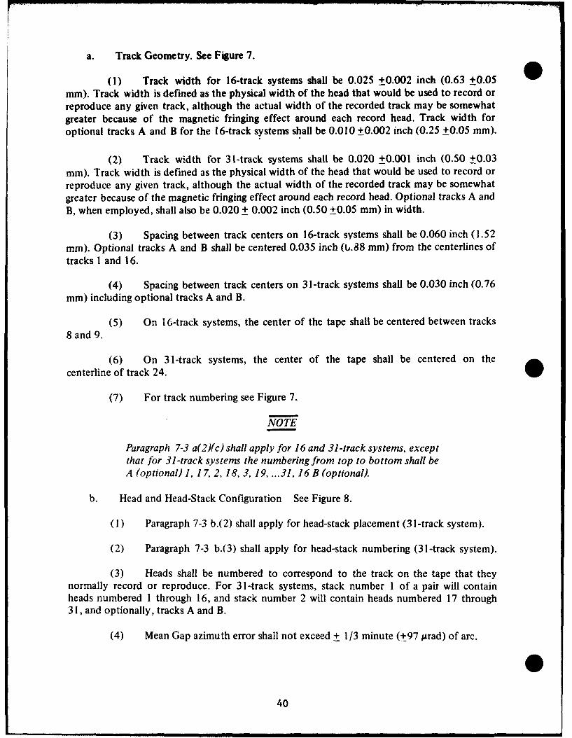
a. Track Geometry. See Figure 7.
(1) Track width for 16-track systems shall be 0.025 +0.002 inch (0.63 +0.05mm). Track width is defined as the physical width of the head that would be used to record orreproduce any given track, although the actual width of the recorded track may be somewhatgreater because of the magnetic fringing effect around each record head. Track width foroptional tracks A and B for the 16-track systems shall be 0.0 10 +_0.002 inch (0.25 +0.05 mm).
(2) Track width for 31-track systems shall be 0.020 +0.001 inch (0.50 +0.03mm). Track width is defined as the physical width of the head that would be used to record orreproduce any given track, although the actual width of the recorded track may be somewhatgreater because of the magnetic fringing effect around each record head. Optional tracks A andB, when employed, shall also be 0.020 + 0.002 inch (0.50 +0.05 mm) in width.
(3) Spacing between track centers on 16-track systems shall be 0.060 inch (1.52mm). Optional tracks A and B shall be centered 0.035 inch (t,.88 mm) from the centerlines oftracks I and 16.
(4) Spacing between track centers on 31-track systems shall be 0.030 inch (0.76mm) including optional tracks A and B.
(5) On 16-track systems, the center of the tape shall be centered between tracks8 and 9.
(6) On 31-track systems, the center of the tape shall be centered on thecenterline of track 24.
(7) For track numbering see Figure 7.
NOTE
Paragraph 7-3 a(2)(c) shall apply for 16 and 31 -track systems, exceptthat for 31-track systems the numbering from top to bottom shall beA (optional) 1, 17, 2, 18, 3, 19, ...31, 16 B (optional).
b. Head and Head-Stack Configuration See Figure 8.
(1) Paragraph 7-3 b.(2) shall apply for head-stack placement (31-track system).
(2) Paragraph 7-3 b.(3) shall apply for head-stack numbering (31-track system).
(3) Heads shall be numbered to correspond to the track on the tape that theynormally record or reproduce. For 31-track systems, stack number 1 of a pair will containheads numbered 1 through 16, and stack number 2 will contain heads numbered 17 through31, and optionally, tracks A and B.
(4) Mean Gap azimuth error shall not exceed + 1/3 minute (t97 prad) of arc.
040

TRACKS A & B TAPE TRAVELTRACK TRAVTH
0, 25 *t0,3Otm• " '
(0.010*0.001o ) 2TRACK SPACING 3TRACKS A & B 40.89 mm (0.035") 5___________
0,76 =a (0.030")-, 6+ 7+.
TAPE q-_----_______ 9 0 ,9 _ _0__ ___ __ 1
0.76 mm (0.030") 1 In 0
TRACK SPACING 12 r4
DATA TRACKS 131,52 mm 14(0.060") _________15
TRACK WIDTH 16DATA0,64 *0,05 mum(0.025"*0.002") OXIDE SIDE OF TAPE
16-TRACK SYSTEM
TRACK SPACING0, 76 mn TAPE TRAVEL(0.030")A
,1 2
19 3
200"010
-210m40022.7 0000TAPE2 a _"e,.8 +01 +
TAPE%4 04"25 1026 o27 11
-28 12,293113
014
mz-15TRACK WIDTH.. 160,50 *0,03 mmuB
(0.020f0.001") OXIDE SIDE OF TAPE31-TRACK SYSTEM
FIGURE 7. PCM TRACK SYSTEM.
441

*96, 76 iRAD(,1/3 MI---
OF ARC) MEAN GAP PERPENDICULAR TO BASEAZZIMUTH
(OPTIO6AL)......
2,89 mm (0.063")
1"" 0,76 mm (0.030")
TAPE STEVEL 9---- TRCK
38,10T" 0,76 n (0.030")
(15±.01)--OPINL
1-6-•DATA TRACK SPACING14--"115252 mm ((..66))
(OPTIONAL) 3---A-- L-- _- -.- . L----0,89 mn (0.035%)
16-TRACK SYSTEM
HEAD STACK SPACVE G
10-1 -00m
(1.5"t0.001") -:B •"--(PINL
1-25
16LSPACING OF HEADS -B3 (OTONL
9- ' -WITHIN STACS -31
14 -_- 1, 52 m , (0. 06 0 ") _- 30-2- -
13--_- -282- T-27
05 TAPE TRAVEL -T2APE6( 0- -25
9- -TAPE
TRACK WIDHG -123 %OF TACK 24
"2- 0, 50 to, 03 0m -262 O TAPE (36- 1(0.02•0J.001- ) -- 21-'']
5- -120
1- -
1--A (OPTIONAL)
STACK 1 STACK 2
31-TRACK SYSTEM
FIGURE 8. PCM HEAD CONFIGURATION.
42

(5) Paragraph 7-3 b.(5) shall apply for head-stack tilt.
(6) Paragraph 7-3 b.(6) shall apply for gap scatter.
(7) The location of any head in a stack shall be within +0.001 inch (+0.03 mm),nonaccumulative, of the nominal position required to match the track location, as set forth inb.(1),(2), (3),(4),(5), and (6) above.
c. Head Polarity. Paragraph 7-3 c. shall apply.
d. Tape Guiding. Tape guides shall provide accurate guidance of the tape across theheads without damaging the tape.
e. Tape Speeds. Paragraph 7-2 a. shall apply.
f. Bit-Packing Density. The playback device shall be capable of playing back datarecorded at bit-packing densities of 1000 bits per linear inch (39.37 bits/mm) per trackmaximum. The nominal maximum bit-packing density at the test ranges shall be 1000 bits perlinear inch (39.37 bits/mm) per track.
g. Total Bit Spacing Error. This shall not exceed 650 microinches (16.51 pm),peak-to-peak with respect to the clocks, from record to reproduce and from machine tomachine.
h. Type of Recording. Nonreturn-to-zero (NRZ) mark recording shall be employedwherein a change in magnetization of the tape from maximum level of one polarity tomaximum level of the opposite polarity is used to indicate the digit one, and no change inmagnetization during a bit interval indicates a zero. Recorder/reproducer electronics shall bedesigned to meet the requirements of paragraphs j and k below.
i. Timing. Track 16 shall be reserved for range timing.
j. Recorder Input Characteristics.
(I) Input impedance shall be 20 kilohms resistive minimum, shunted by 250picofarads maximum.
(2) Input voltage shall be 2-to-20 volts plus, minus, or symmetrical about ground,and polarity-selectable.
(3) Input format shall be parallel inplt, NRZ level.
k. Output Characterisitics.
(1) Reproduce output format shall be parallel output, NRZ level. Reproduceroutput shall compensate for all recorder/reproducer induced time-displacement errors towithin 5.0 per cent of the word interval, or 1.6 microseconds, whichever is greater.
0423

(2) Output impedance shall be 100 ohms maximum.
(3) Output voltage shall be 10 volts peak-to-peak minimum across 1.000 ohmsresistance shunted by no more than 250 picofarads capacitance, one polarity for cne, oppositepolarity for zero, selectable polarity.
7-8. PDM Recording
See Chapter 6. In PDM recording, the duration-modulated rectangular waveform inputsignal is differentiated and the record head is driven with the resulting positive and negativespikes which correspond in time to the leading and trailing edges of the input pulses. Refer toTable 12 for PDM record parameters. The tape is thereby magnetically marked in such amanner that the pulses obtained during the reproduce process may be used to triggerpulse-reconstruction circuitry. Although recorded PDM data may also be reproduced through adirect-record data-reproduce amplifier and pulse reconstruction performed later, a PDMreproduce amplifier reconstructs the original duration-modulated rectangular waveform. PDMsystems may be available with pulse rates not accommodated by these recording standards. Forsuch signals the use of wideband FM or single-carrier FM recording techniques isrecommended.
7-9. Record Amplifier
a. Input impedance shall be 20 kilohms resistive minimum, shunted by 250 picofaradmaximum.
b. Normal input level shall be 1.0 volt, peak-to-peak.
c. Transfer Characteristic. The record amplifier shall drive the record head with apulse signal that is obtained by differentiation of the input duration-modulated rectangularpulse train. The time constant of the differentiation shall be 10 microseconds.
7-10. Reproduce Amplifier
a. Function. The PDM reproduce amplifier will amplify the pulse output of thereprodut-e head and reconstruct the basic duration-modulated rectangular pulse train.
b. Output impedance shall be 100 ohms maximum.
TABLE 12PDM RECORD PARAMETERS
Minimum Tape Speedips (mrm/s) Minimum Pulse Duration
Low Band Intermediate Band Wideband microseconds (ps)
60(1524) 30 '762) 15(381) 7530( 762) 15(381) 7½(190.5) 7515( 381) 7½ (190.5) 33/4 (95.2) 100
44

c. Nominal output level shall be 8 volts, peak-to-peak, across 1.000 ohms resistanceshunted by no more than 250 picofarads capacitance.
d. Rise and decay time of the output rectangular pulses shall be less than 2microseconds from I 0-to-90 per cent amplitude levels.
e. The reproduce amplifier shall incorporate circuitry to detect defective pulses duringthe reproduce process and provide automatic resetting to preclude loss of subsequent data.
45

CHAPTER 8
* MAGNETIC TAPE STANDARDS
Section 1. INTRODUCTION
8-1. General
These standards define terminology, establish key performance criteria and reference testprocedures for instrumentation magnetic tape which is used for telemetry data storage.
Section 11. REFERENCE TAPE SYSTEM
8-2. Purpose
In order to establish, where practical, a set of test procedures which can be carried outindependently and repeatedly on different manufacturers' tape transports with as little specialequipment as possible, a centerline reference tape system should be established by the tapeuser. This reference tape system can be used to provide a centerline standard for aligningoperational recorders for mission support, using the applicable setup procedures contained inChapter 7 or when initiating a tape procurement, as outlined below.
8-3. Manufacturer's Centerline Tape
A Manufacturer's Centerline Tape (MCT) is a tape provided by a manufacturer, at therequest of the tape user, in which all magnetic/electrical characteristics of the tape specified bythe tape user duplicate the manufacturer's own true average (mean) production centerlinewithin +0.5 db. These magnetic/electrical characteristics shall include, but not be limited to,bias level, record level, wavelength response and output at 10 mil (254 gAm) wavelength. Thephysical characteristics of the MCT shall also represent the manufacturer's average (mean)production centerline. The MCT shall be representative of all manufacturer's production tapedelivered under any resultant contractual period. The manufacturer may incorporate anydesired changes in the MCT and production tape at the conclusion of any contract or asspecified by the tape user. Any such change will, however, necessitate the requalification of allcenterline values as outlined in paragraph 8-5 of this chapter.
NOTE
The MCT shall be a full length tape of either V (12. 7 mm) or 1 inch(25.4 ram) width, wound on a 10V½ (266.7 ram) or 14 inch (355.6mam) reel, or as designated by' the tape user. The center one-third ofthe working tape length shall be used as the calibrated working area.
8-4. Manufacturer's Secondary Centerline Tape.
A manufacturer's secondary centerline tape (MSCT) is a tape provided by the
manufacturer in lieu of an MCT. In the MSCT, one or more of the specified magnetic/electricalcharacteristics may depart from the centerline average by more than 0.5 db. All of the
47

specified magnetic/electrical characteristics of the MSCT shall be calibrated to the MCTor tothe manufacturer's own true average (mean) production centerline and any departure fromthese centerline values shall be specified within +0.5 db. The physical characteristics of theMSCT shall, however, represent the manufacturer's average (mean) production centerline. Alladditional MCT requirements shall apply to the MSCT.
8-5. Centerline Performance Requirements.
The tape user procuring magnetic tape shall establish, to the greatest extent possible, theoperational support requirements which the magnetic tape must satisfy. A tape recorder whichmeets both the requirements of Chapter 7 and the above determined operational requirementsshall also be selected for use as a test recorder/reproducer. The tape user will then request fromeach appropriate tape manufacturer, two or more MCT's which meet the requirements of para8-3. If these MCT's cannot be obtained, then a MSCT which meets the requirements of para.8-4 will be an acceptable, but less desirable, alternate.
8-6. MCT/MSCT Use.
Using the MCT or MSCT, the tape user will perform all tests necessary to determine if itsmanufacturer's centerline performance values meet his operational/recorder requirements. Allacceptable MCT's or MSCT's will be retained by the tape user for use as a reference in anysubsequent acceptance test procedures performed in support of resultant contracts orcontractual periods. A working reference tape (WRT), which has been calibrated to the MCTor MSCT, will be used as the actual working reference in the applicable testing proceduresoutlined in Chapter 3, Section V, IRIG 118-73.
8-7. Test Recorder/Reproducer.
A test recorder shall be designated for use in conjunction with the reference tape systemduring any magnetic tape procurement/testing program. The recorder or recorders selectedshall meet the requirements of Chapter 7 and the operational requirements imposed upon thetape. For operating convenience, the test recorder/reproducer selected should be equippedwith adjustable bias and record level monitor meters with readout in db units used in theapplicable test procedures.
8-8. Test Recorder/Reproducer Requirements.
This standard describes the key requirements applicable to high resolution (HR) andstandard resolution (SR) instrumentation magnetic tape. Limits are specified, wherenecessary, to standardize configurations and to establish the basic handling characteristics ofthe tape. The limits placed upon the remaining requirements must be determined by the tapeuser in light of the intended application and interchangeability requirements imposed on thetape. Table 17 contains IRIG Recommended Requirement Limits, which have been selectedon the basis of having provided satisfactory performance in existing telemetry applications.
8-9 General Requirements
a. Marking and Identification. Identification markings shall appear on the reel flangeand individual carton or can of each delivered tape. Tape reel and production information, as
48

specified below, shall be on a removable gummed label on the outer reel flange and on a* permanently affixed label on the carton or can. Shipping containers shall be marked with the
tape and reel identification and such production information as specified by the tape user.
(1) Tape and Reel. The Magnetic Tape shall be identified in the following format:
HR 1.0(25.4) 500(12700)SR 1.5 (38.1) 1000(25400) SCP-l 9200(2804)
Basic Base Thickness Width Reel LengthIndicator Indicator Indicator Indicator Indicator
(a) Basic Indicator. The basic indicator defines the general application of thespecified tape. HR tape is for recording of 0.06 mil (1.52 pm) wavelengths or greater and SRtape is for recording of 0.2 mil (5.08 pm) wavelengths or greater.
(b) Base Thickness Indicator. The base thickness indicator is the nominalthickness of the polyester base material measured in mils (mm).
(c) Width Indicator. The width indicator is the nominal width of the tapemeasured in mils (mm) as specified in Table 13.
(d) Reel and Reel Type Indicator. The reel or reel type is identified inaccordance with Federal Specification W-R-175.
(e) Length Indicator. The length indicator is the designated minimum lengthof tape in feet (meters) as specified in Table 13.
(2) Production Identification. Production identification of the magnetic tape will
be in the following format:
Vendor - Tape Type - Production Date - Production Code
(a) Vendor. Identification of company that manufactures and markets thetape.
(b) Tape Type. Vendor's identifying tape name.
(c) Production Date. Five digit number with first two digits indicating yearof production and last three digits indicating day of production completion. For example,70048 indicates production completed on the 48th day of 1970.
(d) Production Code. Unique code by which the vendor identifies, whereapplicable, the production batch, coater, slitter, and web position of the tape.
49

TABLE 13TAPE DIMENSIONS
TAPE LENGTH/BASE THICKNESS
Designated/Minimum Nominal Base Nominal Reel Nominal HubLength ft (m) Thickness Mils (pm) Diameter in (mm) Diameter in (mm)
2500( 762) 1.5 (38.1) 10.5 (266.7) 4.5(114)3600(1097) 1.0(25.4) 10.5 (266.7) 4.5 (114)4600(1402) 1.0(25.4) 10.5 (266.7) 4.5(114)5000(1524) 1.5(38.1) 14.0 (355.6) 4.5(114)7200(2195) 1.0(25.4) 14.0 (355.6) 4.5(114)9200 (2804) 1.0 (25.4) 14.0 (355.6) 4.5 (114)
10800(3292) 1.0 (25.4) 15.0 (381.0) 4.5 (114)
TAPE WIDTH*
Designated Width Dimension Tolerancein (mm) in (mm) in (mm)
V2 (12.7) 0.498 (12.65) +0.002 (±0.05)1 (25.4) 0.998 (25.35) +0.002 (+0.05)
*See note on Figure 5.
b. Packaging. Each reel of magnetic tape shall be enclosed, as a minimum, by anindividually sealed polyethylene wrapper packaged in an appropriate carton or can whichprovides support of the enclosed reel at the hub.
c. Wind. The tape shall be wound on the reel or hub with the oxide surface facingtoward the hub unless otherwise specified by the tape user. When wound in this fashion, thefront of the wound reel is defined as that flange which is visible when viewing the reel of tapewith the loose end hanging from the viewer's right.
d. Reels and Hubs. Reels and hubs shall conform to the tape-user specifiedrequirements of Federal Specification W-R-175.
e. Radial Clearance. The minimum radial clearance for all tape lengths shall be notless than 0.125 inch (3.175 mm). Radial clearance is defined as the difference in inches(millimeters) in radii between the outside layer of tape and the edge of the reel when the tapeis wound at a tension of 6-to-l0 ounces (1.67 N to 2.78 N) per 1/2 inch (12.7 mm) of tapewidth on a reel that meets the requirements of Federal Specification W-R-l175.
f. Inflammable Materials. Inflammable materials, which will ignite from a matchflame and when so ignited will continue to burn in a still carbon dioxide atmosphere, shall notbe a part of the magnetic tape.
50

g. Toxic Compounds. Compounds which produce toxic effects in the environmentalconditions normally encountered under operating and storage conditions defined in paragraph8-11 b. shall not be part of the magnetic tape. Toxicity is defined as the property of a materialwhich has the ability to do chemical damage to the human body. Highly toxic or corrosivecompounds which are produced under conditions of extreme heat shall be identified anddescribed by the manufacturer.
8-10. Detailed Requirements.
The test procedures cited in the following paragraphs are contained in IRIG 118-73.
8-11. General Characteristics
a. Dimensional Specifications. Magnetic tape shall be supplied on flanged reels in thestandard lengths, widths, and base thickness as outlined in Table 13. Reel and hub diametersare taken from Federal Specification W-R-l175.
b. Environmental Conditions. The tape shall withstand, with no physical damage orperformance degradation, any natural combination of operating or non-operating conditionsdefined in sub-paragraphs (1) and (2). The test procedure outlined in Chapter 3, Section V,paragraph 3-56 a. IRIG 118-73, shall be used to determine compliance with this requirement.
(1) Operating Environmental Conditions.
Condition Range
Temperature: +40°F to + 105°F (277.6 K to 313.8 K)Humidity: 25% to 95% RHBarometric Pressure: 4.6 km (105 kN/m 2 (sea level) to 84 kN/m 2 )
15,000 feet (1050 millibars (sea level) to 840millibars)
(2) Non-operating Environmental Conditions.
Condition Range
Temperature: -200 to + 125 0 F (244.3 K to 324.9 K)Humidity: 5% to 100% non-condensingBarometric Pressure: 15.2 km (105 kN/m 2 (sea level) to 40 kN/m 2 )
50,000 feet (1050 millibars (sea level)to 400 millibars)
c. Storage Life. The tape shall be sufficiently durable, that storage up to 12 months(31.56 Ms), in conditions not exceeding those specified in b. (2) above shall result in nodetrimental effects to the tape. The test procedure outlined in Chapter 3, Section V, paragraph3-57 IRIG 118-73, shall be used to determine compliance with this requirement.
51

d. Bi-Directional Performance. The magnetic/electrical performance of the tape shallremain constant, regardless of the longitudinal direction of tape movement during arecord/reproduce process. The test procedure outlined in Chapter 3, Section V, para. 3-58,IRIG 118-73, shall be used to determine compliance with this requirement.
e. Frictional Vibration. The tape shall not exhibit frictional vibration whichmanifests itself in an audible squeal at any standard IRIG speed as the tape passes over theguides and heads of the test recorder/reproducer. Frictional vibration is defined as the randomfrequency and amplitude modulation which results when the tape passes over the guides andheads of a magnetic tape recorder.
f. Scatterwind. The tape shall be smoothly centerwound on the reel and hub so as toform an integral mass. There shall be no visible folds, shifts, spoking, or gaps between the tapelayers. The edges of the wound tape shall be in a single plane with a minimum of roughnessand with no protruding tape layers or groups of layers.
8-12. Physical Characteristics
a. Yield Strength. The one per cent offset yield point, the force at three per centelongation and the breaking force of the tape when conditioned according to the proceduresdescribed in Chapter 3, Section V, para. 3-59 a(l), IRIG 118-73, shall not be less than theminimum values specified in Table 14. The test procedure outlined in Chapter 3, Section V,para 3-59 a, IRIG 118-73, shall be used to determine compliance with this requirement.
b. Shock Tensile Strength. A sample of tape, ½ inch (12.7 mm) in width, whenconditioned according to the procedures described in Chapter 3, Section V, para. 3-59 b(l)IRIG 118-73, shall possess, as a minimum, the shock tensile strength specified in Table 14.Shock tensile strength is defined as the ability of the magnetic tape to resist, without breaking,a suddenly applied stress. The test procedure outlined in Chapter 3, Section V, para. 3-59 b,IRIG 118-73, shall be used to determine compliance with this requirement.
c. Permanent Elongation. A sample of tape, ½ inch (12.7 mm) in width, whenconditioned according to the procedures described in Chapter 3, Section V, para 3-59 b(3)(a),IRIG 118-73, and stressed as described below, shall not exceed the percentage limits ofpermanent elongation specified in Table 14. Permanent elongation is defined as the differencebetween an initially measured unstressed tape length and a final tape length, expressed as apercentage of the unstressed tape length. The unstressed tape length is the measured distancebetween a point of clamping and a mark on the tape while the tape is under an applied tensionof 50 grams (490 mN). The final length is the measured distance between the point ofclamping and the same mark on the tape under an applied tension of 50 grams (490 mN) afterthe tape has undergone an applied tension of 5 pounds (22N) for a period of 180 minutes(10.8 ks), and thereafter a period of zero tension for 180 minutes (10.8 ks). The testprocedure outlined in Chapter 3, Section V, para. 3-59 b(3), IRIG 118-73, shall be used todetermine compliance with this requirement.
52

TABLE 14TAPE STRENGTH*
Shock Tensile PermanentBase Thickness Yield Strength Strength Elongation
mils(um) pounds (N) foot-pounds (J) (per cent)
1.5 (38.1) 9.8 (43.6) 1.16 (1.570) 0.301.0 (25.4) 6.4 (28.5) 1.16 (1.570) 0.50
*Based on % in. (12.7 mm) tape width.
d. Humidity Stability (Cupping). A sample of tape, '/ inch in width, whenconditioned according to the procedures described in Chapter 3, Section V, para. 3-59 c(l),IRIG 118-73, shall show no cupping in excess of 10 degrees (0.175 rad). Cupping is defined asthe transverse curvature of a strip of tape viewed "end-on." The test procedures outlined inChapter 3, Section V, para. 3-59 c, IRIG 118-73, shall be used to determine compliance withthis requirement.
e. Flexibility. The flexibility of the tape when conditioned according to theprocedures described in Chapter 3, Section V, para. 3-60 a, IRIG 118-73, shall not be less thanthe values specified in Table 15. Flexibility is defined as the ability of the tape to conform to aminimum radius of curvature when subjected to a force normal to the surface of the tape. Thetest procedure outlined in Chapter 3, Section V, para. 3-60, IRIG 118-73, shall be used todetermine compliance with this requirement.
0 TABLE 15FLEXIBILITY
Nominal Width Base Thickness Deflectioninches (mm) Mils (Am) degrees (rad)
½ (12.7) 1.5 (38.1) 350 (0.611)½ (12.7) 1.0 425.4) 450 (0.785)
f. Layer-to-Layer Adhesion. A sample of tape, ½ inch (12.7 mm) in width, whenconditioned according to the procedures described in Chapter 3, Section V, para.3-61 a, IRIG118-73, shall exhibit no sticking or layer-to-layer adhesion when being unwound from a tapepack. Layer-to-layer adhesion is defined as the tendency for one layer of tape to adhere to anadjacent layer in the same pack. The test procedure outlined in Chapter 3, Section V, para.3-61, IRIG 118-73, shall be used to determine compliance with this requirement.
g. Fungus Resistance. The tape shall be sufficiently fungus resistant so that at least 2of 3 test specimens are rated 0 to 1 as defined in MIL-I-63 i D. Each reel or hub of tape shaJl betested completely wound. The test procedures outlined in MIL-I-631D shall be used todetermine compliance with this requirement.
h. Electrical Resistance. The oxide coating of the tape shall be conductive, allowingminimum static charge build-up. When conditioned according to the procedures outlined in
053

Chapter 3, Section V, para. 3-62 a, IRIG 118-73, the electrical resistance of the oxide coatingshall not exceed 100 megohms per square unit of area. The test procedure outlined in Chapter3, Section V, para. 3-62, IRIG 118-73, shall be used to determine compliance with thisrequirement.
i. Tape Abrasivity. The abrasivity of the oxide side of the magnetic tape determinesthe rapidity with which head wear takes place on a recordt .,'--oroducer. Although no absolutemethod of determining tape abrasivity has been developcjx a means exists for accuratelycomparing the relative abrasivity of two test samples. It is therefore recommended that thetape user select a specific centerline tape that has exhibited satisfactory abrasive characteristicsin normal operational use and employ this tape as an abrasivity reference in conjunction withthe test procedure outlined in Chapter 3, Section V, para. 3-63, IRIG 118-73.
8-13. Magnetic/Electrical Characteristics
a. Bias Level. The bias level required by the magnetic tape shall not differ from thebias level requirements of the MCT by more than the amount specified by the tape user. Thebias level of the tape is defined as the amount of high frequency record head input required toachieve the IRIG specified upper-band-edge signal suppression. The test procedure outlined inChapter 3, Section V, para. 3-64, IRIG 118-73, shall be used to determine compliance withthis requirement.
b. Record Level. The record level required by the magnetic tape shall not differ fromthe record level requirements of the MCT by more than the amount specified by the tape user.The record level of the tape is defined as the amount of record head input signal at 1/ 10 upperband edge frequency required to achieve the IRIG specified normal record level. The testprocedure outlined in Chapter 3, Section V, para. 3-64 b., IRIG 118-73, shall be used todetermine compliance with this requirement.
c. Wavelength Response. The output of the magnetic tape measured at thewavelength values listed in Table 16, shall not differ from the output of the MCT by more thanthe amounts specified by the tape user. Wavelength response requirements shall be specified interms of output after having normalized the output to zero at the 10 mil (254 pm) wavelength.
TABLE 16
MEASUREMENT WAVELENGTHS Mils (pim)
High Resolution Tape Standard Resolution Tape
150 (3810) 300 (7620)10 (254) 60 (1524)1 (25.4) 10 (254)0.5 (12.7) 1 (25.4)0.25 (6.35) 0.5 (02.7)0.125 (3.18) 0.25 (6.35)0.10 (2.59) 0.2 (5.08)0.08 (2.03)0.06 (1.52)
54

The test procedure outlined in Chapter 3, Section V, para. 3-64 c., IRIG 118-73, shall be* used to determine compliance with this requirement.
d. Output at 10 Mil Wavelength. The 10 mil (254 pAm) wavelength output of themagnetic tape shall not differ from the 10 mil (254 Am) wavelength output of the MCT bymore than the amount specified by the tape user. The test procedure outlined in Chapter 3,Section V, para. 3-64 c., IRIG 118-73, shall be used to determine compliance with thisrequirement.
e. Short Wavelength Output Uniformity. The short wavelength output of themagnetic tape shall be sufficiently uniform that a signal recorded and reproduced throughoutthe working tape length in either direction of longitudinal tape motion shall remain free fromlong-term amplitude variation to the extent specified by the tape user. Short wavelengthoutput uniformity is defined as the ratio of the peak value of the highest amplitude signalrecovered in the working tape length to the peak value of the lowest amplitude signalrecovered in the working tape length. The test procedure outlined in Chapter 3, Section V,para. 3-64 d., IRIG 118-73, shall be used to determine compliance with this requirement.
f. Short Wavelength Instantaneous Non-Uniformity (Dropout). The instantaneousoutput non-uniformity (dropout) of a recorded signal which is caused by the magnetic tapeshall not exceed the center track and edge track limits specified by the tape user on the basisof dropouts per 100 feet (30.48 m) of nominal working tape length. The nominal dropoutcount shall be determined by totalizing all the dropouts per track over the working tape lengthand dividing by the total number of 100 foot (30.48 m) intervals tested.
ONNOTE
Due to the natural tendency of the edge track to contain moredropouts than the center tracks, it is recommended that center tracksbe used for critical data requirements and that more dropouts beallowed on the edge tracks. Refer to Table 17.
(I) An alternate method of specifying the allowable dropout count is to specifythe maximum number per track for each 100 foot (30.48 m) interval tested. This method maybe desired if critical data is recorded in specific areas of the working tape length.
(2) A dropout is defined as a 6.0 db reduction in output signal amplitude for aperiod of 10 microseconds, when recording and reproducing a short wavelength signal. Signallosses of 6.0 db or greater, which exceed the 10 microsecond time period, shall constitute adropout count for each 10 microsecond time period occurring in the given signal loss. Centertracks are defined as those which are more than one track distant from either edge of the tape,i.e., tracks 2 through 6 of a 7-track system. Edge tracks are defined as those which are nearestto either edge of the tape, i.e.. tracks I and 7 of a 7-track system. The test procedure outlinedin Chapter 3, Section V, para. 3-64 e., IRIG 118-73, shall be used to determine compliancewith this requirement.
g. Durability. The magnetic tape shall resist deterioration in magnetic/electricalperformance due to wear of the coating surface. Signal losses caused by surface wear shall notoccur in excess of the per pass limits specified in Table 18 for the first 35 passes.
55

TABLE 17
SUGGESTED TAPE REQUIREMENT LIMITS
Para. No. Tape Requirement Suggested Limit
8-12, i. Tape Abrasivity No more than 2 times cen f-rline referencetape
8-13, a. Bias Level + 2.0 db
8-13, b. Record Level + 2.0 db
8-13, c. Wavelength Response MeasurementWavelength HR Tape SR Tape
mils (prm) (db) (db)
300 (7620) N/A + 1.5150 (3810) + 1.0 N/A60 (1524) N/A + 1.010 (254) 0 0
1 ( 25.4) + 1.0 + 1.00.5 ( 12.7) + 1.0 + 1.00.25 ( 6.35) + 1.5 + 1.50.20 ( 5.08) N/A +2.00.125 ( 3.18) + 2.0 N/A0.10 ( 2.54) + 2.5 N/A0.08 ( 2.03) + 2.5 N/A0.06 ( 1.52) +3.0 N/A
8-13, d. Output at 10 mil Wavelength + 1.5 db(254 ym)
8-13, e. Short Wavelength Output
Uniformity HR Tape SR Tape
4.5 db 3.0 dbHR Tape SR Tape
8-13, f. Dropouts per 100 ft. 1 MHz Carrier 400 KHz Carrier(30.48 m) at 120 ips at 120 ips
(3048 mm/s) (3048 mm/s)
Center Edge Center EdgeTrack Track Track Track
10 40 20 25
8-13, h. Modulation Noise 1 db maximum
56

TABLE 18DURABILITY SIGNAL LOSSES
Designated Allowable Signal LossesTape Length ft (m) (per pass) db
2500 (762) 23600 (1097) 24600 (1402) 25000 (1524) 27200 (2195) 39200 (2804) 3
10800 (3292) 4
Signal losses in excess of those limits specified above shall not occur during either a record,record/reproduce, or reproduce uninterrupted pass of the working tape length. A signal loss isdefined as a reduction in signal amplitude of 3 db or greater for a time period of 3 through 10seconds of a recorded and reproduced short wavelength signal. Where a continuous loss ofsignal of 3 db or greater exceeds the 10 second time period, a signal loss count shall berequired for every sequential 10 second time period occurring in the given signal loss. The testprocedure outlined in Chapter 3, Section V, para. 3-64 f, IRIG 118-73, shall be used todetermine compliance with this requirement.
h. Modulation Noise. The high frequency amplitude modulation superimposed upona recorded and reproduced signal by the magnetic tape shall not exceed the limits specified by
* the tape user. The test procedure outlined in Chapter 3, Section V, para. 3-64 g, IRIG 118-73,shall be used to determine compliance with this requirement.
i. Layer-to-Layer Signal Transfer. A signal resulting from layer-to-layer signal transfershall be reduced in amplitude from the original signal a minimum of 40 db for 1.0 mil (25.4im) tape and 46 db for 1.5 mil (38.1 pm) tape. Layer-to-layer signal transfer is defined as the
transfer of recording information from a layer of tape in wound reel which has beenprerecorded to saturation, to an adjacent unrecorded layer of tape in the same reel. The testprocedure outlined in Chapter 3, Section V, para. 3-64 h., IRIG 118-73, shall be used todetermine compliance with this requirement.
j. Ease of Erasure. An er:,se field of 1000 oersteds (79.58 kA/m) shall effect at leasta 60 db reduction in output amplitude of a previously recorded 1.0 mil (25.4 /m) wavelengthsignal. The test procedure outlined in Chapter 3, Section V, para. 3-64 i., IRIG 118-73, shall beused to determine compliance with this requirement.
k. Suggested Tape Requirement Limits. Table 17 lists the suggested tape limits to beused for instrumentation tape.
57

CHAPTER 9
TRANSDUCER STANDARDS
Section 1. INTRODUCTION
9-1. General
The vast variety of transducers, currently available for use in telemetry systems, makes itimpractical to develop a standard universally applicable to all transducers, except in the areasof terminology and definitions. Professional societies and similar groups have promulgated anumber of standards and recommended practices pertaining to pirticular classes oftransducers. These documents, which are referenced below, shall be used to the maximumextent possible, in order to achieve the goal of uniformity in the field of telemetry.
9-2. Terminology and Definitions
Terminology and definitions pertaining to transducers are contained in:
a. "A Glossary of Range Terminology," RCC Document 104-64, Revised, Secretariat,Range Commanders Council, 1964.
b. ISA Standard S37.1 "Electrical Transducer Nomenclature and Terminology" (1969)Instrument Society of America, 530 William Penn Place, Pittsburgh, Pa.
Section II. AVAILABLE DOCUMENTATION
9-3. Transducer Characteristics and Performance
The Instrument Society of America has published a number of documents dealing withspecific transducer types. Additional documents are being prepared by committees of theSociety. The published documents are subject to continuing review and users are urged tocontact the Society for the most up-to-date printing.
Documents published to date pertaining to transducers with electrical output are asfollows:
a. RP 31.1 "Terminology and Specifications for Turbine-TypeFlow Transducers," (Volumetric) 1961.
b. RP 37.2 "Guide for Specifications and Tests for PiezoelectricAcceleration Transducers for Aerospace Testing," January 1964.
c. S 37.3 "Specifications and Tests for Strain Gage Pressure
Transducers," 1970.
d. S 37.6 "Specifications and Tests of Potentiometrici Pressure Transducers for Aerospace Testing,"
May 1967.
59

e. ISA "Transducer Compendium" Second Edition, Part 1,Pressure Level, and Flow, Transducers, IFI/Plenum,New York, 1969.
f. ISA "Transducer Compendium" Second Edition, Part 2,Motion, Dimension, Force and Torque and SoundTransducers, IFI/Plenum, New York, 1970.
60

APPENDIX A
FMG FREQUENCY MANAGEMENTPLAN FOR UHF TELEMETRY BANDS
References:
a. Military Communications-Electronics Board Memoranda: MCEB-M 92-65, 19February 1965; 105-69, 24 Feb 69; and, 313-72, 1 Aug 72.
b. IRIG (RCC) Document, Telemetry Standards, Doc. 106-73.
c. Sandia Laboratories Technical Memorandum, SC-TM-68-9, "Frequency ChannelSelection Subject to Constraints," February 1968.
d. Air Force Eastern Test Range/PAA Tech Staff Memo No. 71, ETV-TM-67-16,"Multiple-Link Reception Through Wideband Nonlinear Components," 31 March 1967.
1. Purpose - To provide guidelines for the most effective use of allocated UHF telemetrybands, 1435-1535 MHz and 2200-2300 MHz.
2. Scope - This plan is intended to be utilized as a guide by all managers and users oftelemetry frequencies in the above bands, at National, Service, or other DOD testranges/facilities.
3. General - Essential air-ground telemetering in connection with guided missile, upper airresearch, space, and aircraft flight testing in the past has been accommodated on a primarybasis on 44 channels (500 KHz bandwidth) in the 225-260 MHz portion of the militarycommunications band, 225-400 MHz. The Military Communications-Electronics Board(MCEB) directed DOD agencies remove all telemetering operations from this band by IJanuary 1970. The frequency bands 1435-1535 MHz and 2200-2300 MHz have been allocatedto satisfy displaced and!or future telemetering needs (Ref a). This plan has been devised forapplication where congestion of the allocated telemetry spectrum is expected to be a problem,i.e., at the National and Service Ranges and adjacent areas.
This plan is based primarily on information obtained as a result of empirical andtheoretical analysis, judgements formulated on past experience, and on expectations of futurerequirements and equipment characteristics.
4. UHF Telemetry Radio Frequency Assignments
a. It has been determined that air/space-ground telemetering must be restricted to the1435-1535 MHz and 2200-2300 MHz bands, effective 1 January 1970, in order to permitunrestricted use of the 225-400 MHz military communications band.
b. The band 1435-1535 MHz is nationally allocated for Government/non-Government
A-1

telemetry use for flight testing of manned and unmanned aircraft, missiles, and space vehiclesof major components thereof on a shared basis and the 2200-2300 MHz band is allocated forGovernment fixed anzi ,dobile communications and telemetry on a co-equal basis.
c. Narrowband telemetry channel spacing will be increments of 1 MHz beginning withfrequencies 1435.5 and 2200.5 MHz, respectively. These numbers will be used as the base fromwhich all frequency assignments are to be made. Wideband channels are permitted and will becentered on the center frequency of narrowband channels. Accordingly, all telemetryequipment, whether for narrow, medium, or wideband channel application, must be capable ofoperating on any one MHz increment in the 1435-1535 MHz or 2200-2300 MHz band, withoutinfringing upon adjacent bands.
5. Channel Bandwidth Definitions and Spacing Allocations
To satisfy various channel bandwidth requirements, tne following definitions and spacingallocations will prevail.
a. Narrowband Channel. A channel with a necessary bandwidth of 1 MHz or less.
b. Mediumband Channel. A channel with a necessary bandwidth of more than I MHzbut not greater than 3 MHz.
c. Wideband Channel. A channel having a necessary bandwidth greater than 3 MHzbut not greater than 10 MHz, the assignment of which is to be determined by the serviceinvolved and based on justifiable program requirements.
NOTE 1
Channel bandwidth criteria stated in 5a, b, and c abo'e areequivalent to occupied bandwidths not exceeding 1.2, 3.2, and 10.2MHz respectively, when being modulated, as measured in accordancewith the guidelines outlined in RCC Document. "TelemetryStandards, "at 60 db down from the unmodulated carrier power.
NOTE 2
Necessary bandwidth is defined as the minimum value of theoccupied bandividth sufflicient to insure the transmission ofinformation at the rate and with the quality required for the systememployed, under specified conditions and *for a given class ofemission.
A-2

d. For the purpose of designating channels to satisfy the varying necessarybandwidths, the following normally will prevail. However, it is recognized that for certainrequirements, operational flexibility may necessitate the use of channels centered on anynarrowband center frequency within the allocated bands. Further, the necessary bandwidthused on any particular channel will be contained within the allocated telemetry bandconcerned.
(1) 1435-1535 MHz Band
(a) Narrowband Channel (Center Frequency). 1435.5-1534.5 MHz; in 1 MHzincrements, e.g, 1435.5, 1436.5, 1437.5, etc.
(b) Mediumband Channel (Center Frequency). 1436.5-1532.5 MHz; in 3MHz increments, e.g., 1436.5, 1439.5, 1442.5, etc.*
(c) Wideband Channel (Center Frequency). 1440.5-1520.5 MHz, in 10 MHzincrements, e.g., 1440.5, 1450.5, 1460.5, etc.**
(2) 2200-2300 MHz Band
(a) Narrowband Channel (Center Frequency). 2200.5-2299.5 MHz; in 1 MHzincrements, e.g., 2200.5, 2201.5, 2202.5, etc.
(b) Mediumband Channel (Center Frequency). 2201.5-2297.5 MHz; in 3MHz increments, e.g., 2201.5, 2204.5, 2207.5, etc.*
(c) Wideband Channel (Center Frequency). 2205.5-2285.5 MHz, in 10 MHzincrements, e.g., 2205.5, 2215.5, 2225.5, etc.**
*Center frequencies in this band are predicated on the basis that necessary bandwidth is 3 MHz
in each case.
**Center frequencies in this band are predicated on the basis that necessary bandwidth is 10
MHz in each case.
6. Telemetry Frequency Assignment Guidance
The following information, which is based on the results of tests, theoretical analysis, andjudgments based on past experience, should be used for the guidance of all concerned:
a. Geographical Separation. Two or more telemetry transmitters operatingsimultaneously on the same narrowband channel center frequency must be sufficientlyseparated geographically; otherwise degradation of data is likely to occur.
b. Simultaneous Operations. Two or more narrowband telemetry transmittersoperating simultaneously on the same vehicle or in the same geographical area must be
separated by a minimum of 1 MHz, to preclude degradation of data.
A-3

c. Multi-carrier Operations. If interference is to be precluded or minimized to themaximum extent possible, frequency selection must be made judiciously. Various systematicmethods have been developed for selecting frequencies to accomplish this aim. The followingare model or example sets derived for the selection of a maximum number of frequencies forsimultaneous operations, precluding or minimizing third order intermodulation products:
(1) Model or Example No. 1:
1 MHz Bandwidth Assignments
2201.5 MHz2202.5 MHz2204.5 MHz2208.5 MHz2216.5 MHz2232.5 MHz2264.5 MHz
(2) Model or Example No. 2:
1 MHz Bandwidth Assignments I MHz Bandwidth AssignmentsUsing Even Spacing No. Using Odd and Even Spacing No.
2200.5 MHz 2200.5 MHz (Selections beyond2202.5 MHz 2201.5 MHz this point have not2210.5 MHz 2206.5 MHz been determined due2224.5 MHz 2210.5 MHz to the computations2250.5 MHz 2223.5 MHz necessary. However,2254.5 MHz 2226.5 MHz it will be noted that2270.5 MHz 2234.5 MHz this is the most2282.5 MHz 2241.5 MHz efficient selection2288.5 MHz 2253.5 MHz of frequencies of the
2255.5 MHz examples given.)
NOTE
The above selections do not necessarily reflect all combinationspossible but are offered only as examples of some which have beenascertained as representative possibilities. Methods and/or programshave been developed by Sandia and the AFETR (Ref c and d),among others, which are avaiL-ble upon request.
It can be seen that the frequency spacing in the above examples has avoided (1)duplication of identical frequency spacing and (2) adjacent frequency spacings that can beadded to equal any other frequency spacing or sum of adjacent frequency spacings. Forexample:
Frequency (MHz) 2200.5 2202.5 2206.5 2212.5 2214.5
L JL2L2L 02 4. 6 2
A-4

There are duplicate spacings of 2 MHz each and there will be intermodulation betweenfrequencies 2200.5, 2202.5, 2212.5, and 2214.5 MHz.
Spacings 2 + 4 = 6, and there will be interference between 2200.5, 220f 5, and 2212.5 MHz.
NOTE
The above group of five frequencies has intermodulation problemsand would be a poor choice of frequencies.
d. To minimize interference, a maximum of ten narrowband channels (0 MHzbandwidth or less) may be used simultaneously on the same vehicle/source, within either ofthe two UHF telemetry bands, if their spacing is identical to the example in c(2) above.
e. To preclude interference and overcrowding of the spectrum allocated for telemetry,to the maximum extent possible, use should be made of both UHF bands, 1435-1540 MHz and2200-2300 MHz.
A0
A-5

5.9 STANDARDS FOR THE LEVEL OF UNDESIRED EMISSIONS OUTSIDE THEAUTHORIZED BANDWIDTH FOR TELEMETERING STATIONS, EXCLUDING THOSEFOR SPACE RADIOCOMMUNICATION, IN THE BANDS 1435-1535 and 2200-2290 MHz
5.9.1 General
These standards are applicable to telemetering stations, excluding those for spaceradiocommunication, authorized for operation in the bands 1435-1535 and 2200-2290 MHz.Assignments to such stations include an assigned frequency and an authorized bandwidthcentered on that frequency. The authorized bandwidth is identical to the emission bandwidth,which is indicated by the numerical prefix to the emission designators in the list of FrequencyAssignments to Government Radio Stations, and to the *necessary bandwidth. These standardsare applicable independently of and are not related to any present or future channelization ofthese bands.
5.9.2 Definitions
PT = Transmitter power in watts (unmodulated carrier)
BW = Bandwidth
Authorized BW = Emission BW Necessary BW, in MHz
Fo = Center of BW
A and A'= BW to which all emissions must, as a minimum, be suppressed 60 db or to -25 dbm,whichever is greater.
B and B' = BW to which all emissions must, as a minimum, be suppressed, in db, 55 + 10log I OPT-
5.9.3 Standard for Authorized Bandwidth Equal to or Less TAhan 1 MHz
1. On each side of Fo:
Let A= Authorized BW + Authorized BW
"" - 2 2
Then A = 2 x Authorized BW.
Power Level Limit: In any 3 KHz bandwidth outside bandwidth A, the minimum requiredattenuation for all emissions is 60 db below PT, except that it shall not be necessary in anycase to attenuate below a level of-25 dbm.
*As defined by the ITU Radio Regulations and Section 6. 1.1 of this Manual: For a given class
of emission, the minimum value of the occupied bandwidth sufficient to ensure thetransmission of information at the rate and with the quality required for the system employed,under specified conditions. Emissions useful for the good functioning of the receivingequipment as, for example, the emission corresponding to the carrier of reduced carriersystems, shall be included in the necessary bandwidth.
A-6

2. On each side of Fo:
Let B A + 0.5 MHz.22
Then B = (2 x Authorized BW) + 1.0 MHz.
Power Level Limit: In any 3 KHz bandwidth outside bandwidth B, the minimum attenuationfor all emissions must be in accordance with the following formula:
X = -60 db or to -25 dbm, whichever is greater.Y (in db) = - (55 + 10 IlogPT).
Note: This limits the maximum power level outside B to -25 dbm.
EXAMPLE 1:
Assume an Authorized BW of 0.4 MHz centered on Fo:
A - 2 x Authorized BW B = (2 x Authorized BW + 1.0 MHz)2 x 0.4 =(2 x 0.4) + 1.0
= 0.8 MHz = 1.8 MHz
The illustration below shows the power level limit:
070
0 Odb 0.5)s 0.2)s I.2Hz 10.21s O,2Ms 0.5Hz
" '.. . ..... ..... -IV.- .-
5.9.4 Standard for Author ridwidth Greater Than I MHz
1. On each side of Fo:
Let A'= Authorized BW + 0.5 MHz."2 2
Then A' = Authorized BW + 1.0 MHz.
OA,-7

Power Level Limit: In any 3 KHz bandwidth outside bandwidth A', the minimum requiredattenuation for all emissions is 60 db below PT' except that it shall not be necessary in anycase to attenuate below a level of -25 dbm.
2. On each side of Fo:
Let B' = A' + 0.5 MHz.
Then B' = (Authorized BW) + 2.0 MHz.
Power Level Limit: In any 3 KHz bandwidth outside bandwidth B', the minimum attenuationfor all emissions must be in accordance with the following formula:
X = -60 db or to -25 dbm, whichever is greater.
Y (in db) = - (55 + 10 log 10PT)-
Note: This limits the maximum power level outside B' to -25 dbm.
EXAMPLE 2:
Assume an Authorized BW of 1.5 MHz centered on Fo:
A'= Authorized BW + 1.0 MHz= 1.5 + 1.0= 2.5 MHz
B'= Authorized BW + 2.0 MHz= 1.5 + 2.0= 3.5 MHz
The illustration below shows the power level limit:
F0
PT 0 db 0.5MB: O.5M) 0.75 :z 0.75 M 0.5ma 0.5•1
AuthouIzed ... .S.................. ii..
A-8

APPENDIX B
USE CRITERIA FOR FREQUENCY DIVISION MULTIPLEXING
I. General
The successful application of the Frequency Division Multiplexing Telemetry Standardsdepends upon recognition of performance limits and performance tradeoffs which may berequired in implementation of a system. The use criteria included in this appendix are offeredin this context, as a guide for orderly application of the standards which are presented inChapter 3. AM subcarriers, which include double-sideband (DSB) and single-sideband (SSB)types, as well as FM subcarriers are included.
It is the responsibility of the telemetry system designer to select the range of performancethat will meet his data measurement requirements and at the same time permit him to operatewithin the limits of the standards. A designer or user must also recognize the fact that eventhough the standards for FM/FM and AM/FM multiplexing encompass a broad range ofperformance limits; tradeoffs such as data accuracy for data bandwidth may be necessary.Nominal values for such parameters as frequency response and rise time are listed to indicatethe majority of expected use, and should not be interpreted as inflexible operational limits. Itmust be remembered that system performance is influenced by other considerations such ashardware performance capabilities. In summary, the scope of the standards together with theuse criteria are intended to offer flexibility of operation and yet provide realistic limits.
. 2. FM Subcarrier Performance
The nominal and maximum frequency response of the subcarrier channels listed in Tables2 and 3 is 10 per cent and 50 per cent, respectively, of the maximum allowable deviationbandwidth. The nominal frequency response of the channels employs a deviation ratio of five.The deviation ratio of a channel is defined as one-half the defined deviation bandwidth dividedby the cutoff frequency of the discriminator output filter.
The use of other deviation ratios for any of the subcarrier channels listed may be selectedby the Range Users to conform with the specific data response requirements for the channel.As a rule, the rms signal/noise ratio of a specific channel varies as the three-halves power of thesubcarrier deviation ratio employed.
The nominal and minimum channel rise times indicated in Tables 2 and 3 have beendetermined from the equation which states that rise time is equal to 0.35 divided by thefrequency response for the nominal and maximum frequency response, respectively. Theequation is normally employed to define the 10 to 90 per cent rise time for a step function ofthe channel input signal; however, deviations from these values may be encountered due tovariations in subcarrier components in the system.
0B-i

3. FM Subcarrier Performance Tradeoffs
The number of subcarrier channels which may be used simultaneously to modulate aradio-frequency carrier is limited by the radio-frequency channel bandwidth, and by theoutput signal/noise ratio that is acceptable for the application at hand. As channels are added,it is necessary to reduce the transmitter deviation allowed for each individual channel, to keeptile overall multiplex within the radio-frequency channel assignment. This lowers thesubcarrier-to-noise performance at the discriminator inputs, and the system designer's problemis to determine acceptable tradeoffs between the number of subcarrier channels and acceptablesubcarrier-to-noise ratios.
Background information relating to the level of performance and the tradeoffs that maybe made is included in the "Telemetry FM/FM Baseband Structure Study," Volumes I and II,DDC Documents AD-621139 and AD-621140, which were completed under a contractadministered by the Telemetry Working Group of IRIG. The results of the study show thatproportional bandwidth channels with center frequencies up to 165 KHz andconstant-bandwidth channels with center frequencies up to i76 KHz may be used within theconstraints of these standards. The test criteria included the adjustment of the systemcomponents for approximately equal signal-to-noise ratio at all of the discriminator outputswith the receiver input near radio frequency threshold. Intermodulation caused by the radiolink components carrying the composite multiplex signal limits the channel's performanceunder large signal conditions.
With subcarrier deviation ratios of four, channel data errors on the order of 2.0 per centrms were observed. Data channel errors on the order of 5.0 per cent rms of full-scalebandwidth were observed when subcarrier deviation ratios of two were employed. Whendeviation ratios of one were used, it was observed that channel data errors exceeded 5.0 percent. Some channels showed peak-to-peak errors as high as 30 per cent. It must be emphasized,however, that the results of the tests performed in this study are based upon specific methodsof measurement on one system sample and that this system sample represents a uniqueconfiguration of components. Other components with other performance characteristics willnot necessarily yield the same system performance.
System performance may be improved, in terms of better data accuracy, by sacrificingsystem data bandwidth. That is, if the user is willing to limit the number of subcarrier channelsin the multiplex, particularly the higher frequency channels, the input level to the transmittercan be increased. The signal-to-noise ratio of each subcarrier is then improved through theincreased per-channel transmitter deviation. For example, the baseband structure studyindicated that when the 165 KHz channel and the 93 KHz channel were not included in tileproportional bandwidth multiplex, performance improvement in the remaining channelsequivalent to approximately 12 db increased transmitter power can be expected.
Likewise, elimination of the five highest frequency channels in the constant-bandwidthmultiplex allowed a 6 db increase in performance.
B-2

A general formula which can be used to estimate the thermal noise performance of an* FM/FM channel above threshold6 is as follows:
(S) (S> (&) "2 Bcd Y2 (fdci) )lN ) N )c 4 ud ýs ýud)
where
S) discriminator output signal-to-noise ratio
( d (rms voltage ratio)
s) oareceiver carrier-to-noise ratio (rms
N voltage ratio)
Bc carrier bandwidth (receiverintermediate-frequency bandwidth)
Fud subcarrier discriminator output filter - 3 db
frequency
fs = subcarrier center frequency
fdc = carrier peak deviation due to the particularsubcarrier of interest
fds = subcarrier peak deviation
If the RF carrier power is such that the thermal noise is greater than the intermodulationnoise, the above relation provides estimates accurate to within a few decibels.
The FM/FM composite multiplex signal used to modulate the radio-frequency carrier maybe a proportional-bandwidth format, a constant-bandwidth format, or a combination of thetwo types provided only that guard bands allowed for channels used in a mixed format beequal to or greater than the guard band allowed for the same channel in an unmixed format.
4. FM System Component Considerations
System performance is dependent upon essentially all components in the system.Neglecting the effects of the radio-frequency and recording system, data channel accuracy isprimarily a function of the linearity and frequency response of the subcarrier oscillators anddiscriminators employed. Systems designed to transmit data frequencies Lip to the nominalfrequency responses indicated in Tables 2 and 3 have generally well-known responsecapabilities, and reasonable data accuracy estimates can be easily made. For data channelrequirements approaching the maximum frequency response of Tables 2 and 3, oscillator anddiscriminator characteristics are less consistent and less well defined, making data accuracyestimates less dependable.
B-3

The effect of the radio-frequency system on data accuracy is primarily in the form ofnoise due to intermodulation at high radio-frequency signal conditions well above threshold.Under low radio-frequency signal conditions, noise on the data channels is increased due to thedegraded signal-to-noise ratio existing in the receiver.
Intermodulation of the subcarriers in a system is due to characteristics such as amplitudeand phase nonlinearities of the transmitter, receiver, or other system components required tohandle the multiplex signal under the modulation conditions employed. In systems employingpre-emphasis of the upper subcarriers, the lower subcarriers may experience intermodulationinterference due to different frequencies of the high-frequency (and high-amplitude)channels.
The use of magnetic tape recorders for recording a subcarrier multiplex may degrade thedata channel accuracy, primarily due to tape speed differences or variations between recordingand playback. These speed errors can normally be compensated for in present discriminatorsystems when the nominal response rating of the channels is employed and a referencefrequency is recorded with the subcarrier multiplex.
5. Range Capability for FM Subcarrier Systems
a. Receivers and Tape Recorders
The use of the 93, 124, and 165 KHz proportional channels or the correspondingconstant-bandwidth channels may require discriminators or tape recorders of a greatercapability than are in current use at some ranges. It is recommended that users who anticipateemploying any of the above channels at a range, check the range's capability at a sufficientlyearly date to allow procurement of necessary equipment.
b. Discriminator Channel Selection Filters
Inclusion of the higher frequency proportional-bandwidth channels and theconstant-bandwidth channels will require the ranges to acquire additional band selectionfilters. In applications where minimum time delay variation within the filter is important, suchas tape speed compensation, or high rate PAM or PCM, constant-delay filter designs arerecommended.
c. Discriminator Output Filters
If a range facility were to stock discriminator output filters corresponding to each ofthe channel frequency responses listed in Tables 2 and 3, it would be necessary toaccommodate 64 separate cutoff frequencies. This number must be multiplied if more thanone roll-off stop is required. In order to place a more modest requirement on the rangefacilities, output filters with the following cutoff frequencies are recommended.
A filter for each of the frequencies listed under nominal frequency response inTable 3 plus 6500, 8500, 11,000, 19,000, and 24,000 Hz. In addition, filters are recommendedcorresponding to each of the nominal and maximum frequency responses listed in Table 3..For other data frequency requirements, compromises should be made by selecting one of thefilter frequencies already listed.
B-4

6. AM Subcarrier Background
AM Systems, Single Sideband Suppressed Subcarriers (SSB) and Double SidebandSuppressed Subcarriers (DSB), are wide bandwidth frequency multiplexing systems designedprimarily for the application of telemetering vibration type data. These systems are in a sense"adaptive" when used with a transmitter modulation control (TMC) because the deviation ofthe FM transmitter assigned to each channel changes according to the data activity of all thechannels. The data channels also adapt by permitting greater dynamic amplitude changes ofthe data to be transmitted without adjacent channel interference.
The signal-to-noise ratio for a particular AM/FM channel considering only thermal noiseeffects can be estimated from the following formula:
(S ( [ C] 12 (sc)
a = -demodulator output signal-to-noise ratio
N d (rms voltage ratio)
( ~ receiver carrier-to-noise ratio (rmsc = voltage ratio)
Bc carrier bandwidth (receiver intermediate-frequencybandwidth)
Fud subcarrier demodulator output filter - 3 dbfrequency
fs = subcarrier center frequency
frc = carrier rms deviation due to the particularsubcarrier of interest
The S/N ratios derived from these formulas are based on the idealized performance of thetransmission system. The formulas do not take into account any of the degrading factors suchas nonlinearities of the RF system hardware. 7 The transmitter deviation assigned to aparticular subcarrier, frc' in an AM baseband system is not a fixed value as it is in an FMsubcarrier system. The Transmitter Modulation Control will increase and decrease frc with thedata activity. A S/N improvement of one channel is obtained through the inactivity of otherchannels because the deviation of that channel is increased by the TMC to compensate for thedecrease of the other channels.
The use of a TMC can result in system errors. The gain changes caused by the TMC mustbe tracked out by a ground AGC circuit called the Baseband Level Control (BLC). Rapidvariations in the Composite Multiplex Signal (CMS) rms value create tracking problems for
* TMC and BLC and will cause these circuits to impress waveform errors on all channels passingthrough "hem.8
B-5

DSB systems are capable of transmitting data from DC to the upper frequency limit of theselected channel. SSB systems are capable of transmitting data from around 10 Hertz to theupper frequency limit of the selected channel. The low end frequency response depends uponthe modulation and demodulation techniques used in the hardware design. The AM standardspermit transmission of data in the upper or the lower sideband of a SSB subcarrier. It is alsopossible that both sidebands could be used simultaneously to transmit different channels ofdata.
The channel spacing intervals for the SSB and the DSB systems make it possible tointermix these systems with Constant Bandwidth (CBW) FM subcarrier systems. It is alsopossible to intermix the Proportional Bandwidth (PBW) FM subcarriers with the AM basebandsubcarriers. Careful selection of the proper guardband spacing is required when intermixing FMsubcarrier; with AM subcarriers.
The standards permit the utilization of two techniques, the Harmonic Subcarrier Method(HSM) and the Independent Subcarrier Method (ISM), to generate DSB subcarriers. (SSBformats can be utilized only with HSM.) Table 5 in the standards is a guide for the doublesideband AM subcarrier channels relating to an ISM system. The HSM system channel spacingis defined in Chapter 3, para. 3-7. It permits the placement of the channel frequencies atvarious 4 KHz intervals according to the formula Fc = 4n. The frequencies outlined in Table 5are a sub-set of those that can be derived from the basic formula. The formula provides theflexibility to adjust the assignment of the wideband width channels and the necessary pilot andambiguity tones to a configuration which conserves baseband efficiency.
7. AM Airborne Systems
a. DSB Systems
(I) HSM System
The HSM uses frequency synthesis techniques to derive the modulating carriersplus a sinusoidal signal called the common pilot tone (CPT) from a single stable oscillator. Thecommon pilot tone is then summed with the channel signals occupying a baseband channellocation reserved for this purpose. For demodulation, the CPT is separated from the compositemultiplex signal, iiltered and conditioned to minimnize the effects of noise, and used as areference signal for generation of the demodulation reference carriers. The CPT also providesinformation needed for the TMC and BLC.
A reference carrier constructed from the common pilot tone can appear in anyone of a discrete set of phase relationships, only one of which corresponds to the desireddemodulation reference carrier phase. Selection of the correct phase position requiresinformation other than that contained in the CPT itself. This additional reference informationcan be provided by inserting a carrier component without very low-frequency datacomponents in a ,hannel. This signal is called the ambiguity reference tone (ART). The zerophase reference point for each subcarrier is the time when the CPT and the ART havesimultaneous positive-going zero crossings.
B-6

If the channels of an HSM airborne multiplex are all loaded with a single polarityDC signal, then a spike resembling a doublet impulse function will occur every 250microseconds in the composite multiplex signal (CMS). An HSM system should not be used totransmit a large number of channels carrying only single polarity DC signals because the FMtransmitter, receiver, or tape recorder may not be able to satisfactorily handle the doubletimpulse function.
If single polarity DC data must be transmitted on most of the channels in anHSM system, the polarity of some of the voltages should be inverted to cause the subcarrierphases to be reversed. The phases of the subcarriers themselves can also be shifted within theairborne package to reduce the possibility of over-deviation of the airborne transmitter. Inorder to properly demodulate such an HSM airborne system, the ground station would have toknow the phase of all of the subcarriers as referred to the zero phase point. If multipleairborne phases are used within the system (they are permitted by the standards), thecomplexity of the ground station will be greatly increased since it must be capable ofgenerating all uscd phases.
The HSM standards call for the placement of two tones, the common pilot toneand the ambiguity reference tone in the airborne composite multiplex signal. In order for thecommon pilot tone to operate properly it must be placed within the transmitter modulationcontrol loop so that its amplitude is adjusted as the CMS is adjusted by the transmittermodulation control.
If the AR f goes through the TMC/BLC circuits, the amplitude of the ART mustbe selected so that the ground synthesizer will always have an adequate signal-to-noise ratiothroughout the complete dynamic operating range of the TMC/BLC circuits. If the ARTbypasses the TMC/BLC circuits, the ground synthesizer must be capable of compensating forstatic phase differences in the two signal paths and there must not be any circuits that willcause dynamic phase shifts of either tone.
(2) ISM System
An ISM airborne package uses independent oscillators for generating eachsubcarrier. The oscillators should be stable enough to prevent excessive frequency drift. If theoscillator frequency drifts more than 200 or 300 Hertz from the center frequency it rn:ay gobeyond the acquisition range of the subcarrier regeneration phase lock loop (PLL) in theground station. Even if the regeneration phase lock loop can acquire, the performance of thecarrier regeneration circuit may be degraded by forcing the PLL to track an offset subcarrier inthe presence of noisy signals and tape recorder flutter.
Since the phase of all subcarriers is completely random in an ISM multiplex, theprobability is low that there will be any periodic impulse spikes in the CMS when transmittingDC data of a single polarity.
B-7

The common pilot tone in the ISM composite multiplex signal serves twofunctions. It is used as the reference for the operation of the ground equipment's BasebandLevel Control (BLC) circuitry. The CPT is also fed to the data channels in the airborne package 0to furnish them with low level sidebands and a channel ambiguity reference tone. It is notnecessary to include the CPT as part of the signal transmitted on channel if the user of the datacan accept some system limitations in the demodulation process. These will be discussed underthe ground system section.
b. SSB Systems
An airborne SSB modulator translates the input data spectrum to a new location inthe frequency domain and produces either a direct or mirror image for the upper or lowersideband, respectively. In actual practice the SSB modulator produces a DSB signal andremoves the unwanted sideband by a filtering or phasing operation. Since it is not possible toachieve an infinitely sharp cutoff characteristic, a residual portion of any very low frequencycomponents in the data signal referred to as the vestige, will appear in the opposite sideband.
SSB is well suited for the transmission of data to be used for power spectral densityanalysis. The lack of DC response and the nonlinear phase characteristics at low frequencies arenot too critical for this application. The SSB systems implemented to date have used only acommon pilot tone and no ambiguity reference tone, which means the ground equipment canonly determine the proper frequencies for the reinserted subcarriers used for translatingthe sideband spectra back to its proper place in the spectrum.
Airborne SSB systems utilize the same frequency synthesis techniques as HSM DSBsystems, hence, SSB and HSM subcarriers may be easily intermixed.
c. Pre-Emphasis
It is the generally accepted practice to apply a pre-emphasis curve in a multiplex ofFM subcarriers. Since DSB subcarriers are equal bandwidth channels, the same pre-emphasis asused on DBW-FM subcarriers should also be applied if CMS is not being passed through a TMCcircuit. There are, however, a number of reasons why this practice should be carefully studiedbefore adapting it for an AM baseband system if TMC is used. Pre-emphasis might help somehigh-frequency channels only to the detriment of the low-frequency channels which might besignificantly degraded by the intermodulation effects of the transmitter-receiver link.
Pre-emphasis of high-frequency channels could lead to transmitter spectrumspreading problems if the low-frequency channel activity decreased to zero, thereby causingthe TMC to assign increased deviation to the already emphasized high channels. If thepre-emphasis taper was achieved by a network after the TMC, then less than optimumdeviation of the FM transmitter would result if high-frequency channel activity decreased.Some of the adaptive properties of an AM system are lost with less than optimum deviation ofthe transmitter.
0B-8
8. AM Ground System
a. General
The input level to anl FM ground system from a receiver or tape recorder is not toocritical since most FM discriminators will operate over a very wide dynamic range. This is nottrue with an AM ground station operating in conjunction with an airborne system using aTMC. The first operating stage of such a DSB or SSB ground system is the baseband levelcontrol (BLC). Channels not passing through the TMC should also bypass the BLC circuitry.The BLC is designed to restore in the ground system the original amplitude of the CMS as itwas produced in the airborne package. If the amplitude into the BLC is greater than itsdynamic range or less than its operating AGC range, the BLC may move to a nonlinearoperating point which will cause intermodulation among the channels. The user mustdetermine the dynamic range of his particular BLC and see that the composite multiplex signalis held within that range.
An AM system requires that the baseband video output of the receiver have a flatamplitude response and the linear phase characteristics for the portion of baseband occupiedby the CMS. Differences in the haseband amplitude will cause gain problems with the DSBchannels. Some of the receiver variations can be compensated for by inflight calibration of thechannels or by the optional use of the channel reference tones (CRT) in the airborne package.The CRT working through a channel level control (CLC) can compensate for minor differencesin baseband frequency response and the effects of static phase shift on the demodulator gain.
b. DSB Ground Systems
(1) HSM System
An HSM system will be sensitive to the static baseband phase shifts of the FMreceiver because the subcarrier synthesizer reproduces subcarriers from the CPT and ARTcoming from one part of the baseband and multiplies them with data channels from otherparts of the baseband. Ground station adjustments should be made to minimize the phasedifferences which would produce amplitude errors in the output data, and increase the errorsdue to tape flutter and jitter of the phase reference.
The standards permit the use of the ART as a carrier for data if the frequencyband within +50 Hz of the carrier is kept free of data components. A wider band may well berequired for the subcarrier synthesizer in some ground station designs.
(2) ISM System
The ISM demodulatior process requires that the channel reference tones bepresent in order to maintain constant lock-up of the subcarrier regeneration loop in theabsence of data sidebands. If a loss of data during the time lag required for the lock-up of thesubcarrier regeneration loop is permissible, then the channel reference tones need not beincluded. Also, without the tones the data will have a possibility of 1800 phase ambiguity.This may not be a serious problem if the data are to be used only for power spectral densitymeasurements. If a channel reference tone is not present, then some means of deactivating theCLC must be provided to keep it from limiting the channel signals.
B-9

Table 5 lists frequencies for an ISM system down to 4 KHz. A system designer
may encounter difficulties in utilizing channels DAI and DA2 within an ISM system. One
difficulty is that these channels may at times conflict with the common pilot tones used in the
CMS. Secondly, a channel subcarrier recovery method 9 which detects the zero crossing of the
carrier may introduce minor perturbations in the reconstructed subcarrier due to the
additional zero crossing produced by the data.
c. SSB Ground System
An SSB demodulator which has received its subcarrier from a ground synthesizer that
utilizes only the frequency information of the CPT will shift the output data components by
an angle equal to the phase error of the reinserted subcarrier. Since distortionless transmissionrequires that the phase shift be proportional to frequency, shifting each wave form frequency
component by an equal angle creates waveform distortion. The amplitudes of sinusoidalcomponents in the output are unaffected, so no error will result if the data are to be used onlyfor power spectral density analysis.
If the ground synthesizer uses the ART to resolve the phase of the reinsertedsubcarrier, then the only waveform distortion in the output will be caused by the phase shift
of low-frequency data components which occurs during the generation or demodulationprocesses.
d. Compatible AM Ground Stations
It is possible to design a number of compatible ground station combinations. Forexample, an HSM ground system can be designed to demodulate either upper or lower SSBsignals and even an amplitude modulation technique not included within the standards knownas Quadrature Double Sideband (QDSB). Such a station cannot demodulate an ISM subcarrier.It is possible, however, for an ISM ground station to demodulate an HSM generated channel ifthe proper CPT and channel reference tone are present. With proper considerations it ispossible to design a station which would demodulate both HSM and ISM DSB signals if thosewere the only two systems contemplated for use by the designer.
e. AM System Filters
The user who contemplates building a compatible AM ground station should give somethought to standardizing the frequencies in Table 5 for any bandpass filters that may berequired for DSB channel demodulation. SSB filters will have to be selected according toanticipated use.
If a channel reference tone is multiplexed with the transmitted data, it may benecessary to suppress it before the data are presented to the user. One method of removing thechannel reference tone is to include a sharp notch in the low pass output filter. This notchcauses the filter to have sharp cutoff characteristics and hence may not be optimum for sometypes of data. The sharp cutoff filter requirement is not necessary in an HSM demodulationstation unless it, too, is using channel reference tones. Different sets of low pass filters arerequired for each of the channel reference tones used in the system.
B-10

9. Tape Recording
Tests conducted upon the recording of ISM DSB signals10 have shown that predetectionrecording produces better signal-to-noise ratio than post detection recording of the signal. It isassumed that the same is true for other AM baseband systems. The number of tape dropoutsand the possibility of nonlinear recording is further reduced by using predetection recording. Itis expected that wideband FM recording of post-detection signals would also be better thandirect recording.
B-l1

APPENDIX C
PCM STANDARDSADDITIONAL INFORMATION AND RECOMMENDATIONS
I. Bit Rate Versus Receiver Intermediate-Frequency Bandwidth (3 db Points)
a. Receiver intermediate-frequency (IF) bandwidth should be made from those listedin Table 6. Only those discrete receiver intermediate-frequency bandwidths listed should beused for data channel (optional below 12,500 Hz). The selections in Table 6 have been madeon the consideration that automatic tracking of radio-frequency (RF) carrier drift or shift willbe used in the receiver; however, doppler shift considerations may require wideIntermediate-Frequency/Discriminator Bandwidths for the AFC System.
b. For reference purposes in a well designed system, a receiver intermediate-frequencysignal-to-noise ratio (power) of approximately 15 db will result in a bit error probability ofabout I bit in 106. A 1 db change (increase or decrease) in this signal-to-noise ratio will resultin an order of magnitude change (107 or 105 from 106, respectively) in the bit error
probability.
c. It is recommended that the period between assured bit transitions be a maximum of64-bit intervals to assure adequate bit synchronization.
2. Suggested PCM Synchronization Patterns
It is suggested that an N-bit frame-synchronization pattern be selected under the criterionthat the probability of displacement of the pattern by ± 1 bit be minimized at the same time,restricting the probability of pattern displacement by 2 to (N-I) bits below a prescribedmaximum. A 31-bit synchronization pattern satisfying this criterion is0101011010100101101001101010111.
3. Premodulation Filtering
The premodulation filter recommended in Chapter 6, para. 6-7 shall exhibit a finalattenuation slope of 36 db per octave and shall have a maximally linear phase response.
C-1
APPENDIX D
PAM STANDARDSADDITIONAL INFORMATION AND RECOMMENDATIONS
I. Intermediate-Frequency Bandwidth and Transmitter Deviation
The appropriate receiver final intermediate-frequency bandwidth and transmitterdeviation depend primarily on the total pulse rate, system noise, and distortion tolerance.
2. Premodulation Filtering
The premodulation filter recommended in Chapter 5 para. 5-6 exhibits a final attenuationslope of 36 db per octave and shall have a maximally linear phase response.
D-1

APPENDIX E
PDM STANDARDSADDITIONAL INFORMATION AND RECOMMENDATIONS
I. Intermediate-Frequency Bandwidth and Transmitter Deviation
The appropriate receiver final intermediate-frequency bandwidth and transmitterdeviation depend primarily on the total pulse rate, system noise and distortion tolerance.
2. Premodulation Filtering
The premodulation filter recommended in Chapter 6, para. 6-7 exhibits a final attenuationslope of 36 db per octave and shall have a maximally linear phase response.
3. Maximum Pulse Duration
The accuracy of a PDM system is a direct function of the timing measurement errors(jitter) on the leading and trailing edges of the pulses. The full-scale accuracy will improve asthe duration of the maximum length pulse is increased.
The minimum Pulse Gap Time interval must be larger than the minimum pulse duration inorder to avoid transient interference between successive data pulses (See Telemetry SystemStudy Final Report, Aeronutronics U743, 18 December 1959, Vol. I Section 2, page 36).
E-1

APPENDIX F
MAGNETIC TAPE RECORDER/REPRODUCERINFORMATION AND USE CRITERIA
I. Configurations not now included in IRIG Standards
Special applications of recorder/reproducer equipment have resulted in manyconfigurations not now included in IRIG Standards. Among those which show promise inimproving recording and tape-use efficiency are the high-density track configurations proposedby the Electronic Industries Association P 8.7 Working Group on Instrumentation MagneticTape Recording and the double-density wideband recording systems under development byseveral manufacturers.
a. Double-density recording
Systems have been demonstrated using special heads and modified electronics, andspecial high-output magnetic tape which will give direct recording to 1.5 MHz at 60 ips (1524mm/s) without serious degradation of system signm-l-to-noise ratio. If field experience provesthese systems reliable over a reasonable operating time, economies in tape use could result.
b. High-density track configuration
EIA has proposed standardization of tape track configurations resulting in 14 and 21tracks on /2 inch (12.7 mm) magnetic tape and 28 and 42 tracks on 1-inch (25.4 mm) magnetictape. Systems for I-inch (25.4 mm) tape have been manufactured. The EIA proposed trackconfigurations as modified by the International Standards Organization (150/TC97/SC4/WG5)Nov. 1971 are shown in Tables 19 through 22. Also see Figure 5 and Table 13.
c. Several methods for recording serial PCM data at bit-packing densities of 20,000bits per inch or greater have become available. These methods employ some form of a biphasecode such as the Manchester code. These encoding methods ensure enough flux transitions thatDC or very low frequency response is not required. Additionally, bit-rate recovery is enhancedso that reproduce electronics can be phase-locked to the bit stream and provide coherentrecovery.
For these systems wideband instrumentation recorders are employed, but specialrecord and reproduce electronics are required.
Standards have not been prepared in this area, but such systems appear attractive forrecording large quantities of PCM data.
2. Gap Scatter - The distance between two lines perpendicular to the Head ReferenceSurface which contains components of azimuth misalignment and deviations from the averageline defining the azimuth. Since both components affect data simultaneity from record to
F-1

TABLE 19
Dimensions - Recorded Tape Format
14 Tracks on ½-Inch (12.7 mm) Wide Tape(Refer to Figure 9)
Track Width (W) 0.025 + 0.001 in (0.64 + 0.03 mm)
Track Spacing (D) 0.035 in (0.89 mm)
Data Spacing (s) 1.500 + 0.001 in (38.10 + 0.03 mm) Fixed1.500 + 0.002 in (38.10 + 0.05 mm) Adjustable
Edge Margin, Minimum (Mm) 0.005 in (0.13 mm)
Track Location (reference edgeto Track # I centerline) (G) 0.020 + 0.0015 in (0.50 + 0.04 mm)
Track Spacing Tolerence (AHn) 0.0015 in (+ 0.04 mm)
Track Number (Hn)Inches Millimetres
1 0.000 0.0002 0.035 0.893 0.070 1.784 0.105 2.675 0.140 3.566 0.175 4.457 0.210 5.348 0.245 6.239 0.280 7.12
10 0.315 8.0111 0.350 8.9012 0.385 9.7913 0.420 10.6814 0.455 11.57
F-2

TABLE 20
Dimensions - Recorded Tape Format
21 Tracks on 'A-Inch (12.7 mm) Wide Tape(Refer to Figure 9)
Track Width (W) 0.0 18 + 0.001 in (0.46 + 0.03 mm)
Track Spacing (D) 0.023 in (0.585 mm)
Data Spacing (S) 1.500 + 0.001 in (38.10 + 0.03 mm) Fixed1.500 + 0.002 in (38.10 + 0.05 mm) Adjustable
Edge Margin, Minimum (Mm) 0.007 in (0.17 mm)
Track Location (reference edgeto Track # 1 centerline) (G) 0.07 + 0.0015 in (0.44 + 0.04 mm)
Track Spacing Tolerence (AHn) + 0.001 in (+ 0.03 mm)
Track Number (Hn)
Inches Millimetres
1 0.000 0.0002 0.023 0.5853 0.046 1.1704 0.069 1.7555 0.092 2.3406 0.115 2.925
7 0.138 3.5108 0.161 4.0959 0.184 4.680
10 0.207 5.26511 0.230 5.85012 0.253 6.43513 0.276 7.02014 0.299 7.60515 0.322 8.19016 0.346 8.77517 0.368 9.36018 0.391 9.94519 0.414 10.53020 0.437 11.11521 0.460 11.700
F-3

TABLE 21
Dimensions - Recoded Tape Format
28 Tracks on 1-inch (25.4 mm) Wide Tape(Refer to Figure 9)
Track Width (W) 0.025 + 0.001 in (0.64 + 0.03 mm)
Track Spacing (D) 0.035 in (0.89 mm)
Data Spacing (S) 1.500 + 0.001 in (38.10 + 0.03 mm) Fixed1.5 + 0.002 in (38. 10 + 0.05 mm) Adjustable
Track Location (Reference Edgeto Track # I centerline ) (G) 0.026 + 0.0015 in (0.60 + 0.04 mm)
Edge Margin Minimum Mm) 0.009 in (0.22 mm)
Track Spacing Tolerence (AHl) + 0.002 in (+ 0.04 mm)
Track Number (Hn)Inches Millimetres
1 0.000 0.002 0.035 0.893 0.070 1.784 0.105 2.685 0.140 3.566 0.175 4.457 0.210 5.348 0.245 6.239 0.280 7.12
10 0.315 8.0111 0.350 8.9012 0.385 9.7913 0.420 10.6814 0.455 11.5715 0.490 12.4616 0.525 13.3517 0.560 14.2418 0.595 15.1319 0.630 16.0220 0.665 16.9121 0.700 17.8022 0.735 18.6923 0.770 19.5824 0.805 20.4725 0.840 21.3626 0.875 22.2527 0.910 23.1428 0.945 24.03
F-4
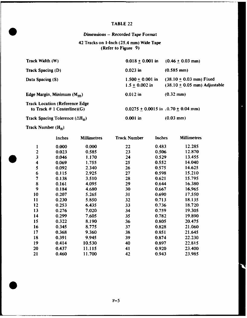
TABLE 22
Dimensions - Recorded Tape Format
42 Tracks on 1-Inch (25.4 mm) Wide Tape(Refer to Figure 9)
Track Width (W) 0.018 + 0.001 in (0.46 + 0.03 mm)
Track Spacing (D) 0.023 in (0.585 mm)
Data Spacing (S) 1.500 + 0.001 in (38.10 + 0.03 mm) Fixed1.5 + 0.002 in (38.10 + 0.05 mm) Adjustable
Edge Margin, Minimum (Mm) 0.012 in (0.32 mm)
Track Location (Reference Edgeto Track # 1 Centerline)(G) 0.0275 + 0.0015 in 0.70 + 0.04 mm)
Track Spacing Tolerence (AHn) 0.001 in (0.03 mm)
Track Number (Hn)
Inches Millimetres Track Number Inches Millimetres
1 0.000 0.000 22 0.483 12.2852 0.023 0.585 23 0.506 12.8703 0.046 1.170 24 0.529 13.4554 0.069 1.755 25 0.552 14.0405 0.092 2.340 26 0.575 14.6256 0.115 2.925 27 0.598 15.2107 0.138 3.510 28 0.621 15.7958 0.161 4.095 29 0.644 16.3809 0.184 4.680 30 0.667 16.965
10 0.207 5.265 31 0.690 17.55011 0.230 5.850 32 0.713 18.13512 0.253 6.435 33 0.736 18.72013 0.276 7.020 34 0.759 19.30514 0.299 7.605 35 0.782 19.89015 0.322 8.190 36 0.805 20.47516 0.345 8.775 37 0.828 21.06017 0.368 9.360 38 0.851 21.64518 0.391 9.945 39 0.874 22.23019 0.414 10.530 40 0.897 22.81520 0.437 11.115 41 0.920 23.40021 0.460 11.700 42 0.943 23.985
F-5

S - Ref. Edge
w
G
D H2
x .
Tape Travel (Magnetic Surface Side)
Valutis Of X For Different Tape Widths:
0.498 f- 0.002 in 0.998 + 0.002 in(12.65 + 0.05 mm) (25.35 + 0.05 mm)
* These items deleted by ISQ/TC97/SC4/WG-5, Nov 1971.
FIGURE 9. RECORDED TAPE FORMAT
F-6

reproduce, the measurement is the inclusive distance containing the combined errors. Since* azimuth adjustment affects the output of wideband systems a 0.0002-inch (5.08 pum) gap
scatter is allowed for such recorder/reproducers, whereas a 0.0001-inch (2.54 pm) gap scatteris recommended for fixed-head systems (see upper illustration in Figure 6).
3. Head Polarity
The requirement that a positive pulse at a record amplifier input generate a S-N-N-Smagnetic sequence and that a S-N-N-S magnetic sequence on tape produces a positive pulse atthe reproduce amplifier output still leaves two interdependent parameters unspecified. Theseare (1) polarity inversion or non-inversion in record and/or playback amplifiers, and (2) recordor playback head winding sense. For purposes of head replacement it is necessary that theseparameters be determined by the Range so that an unsuspected polarity inversion on-tape oroff-tape will not occur after heads are replaced.
4. Record Level
Normal Record Level is established as the level of a sinusoidal signal of 0.1 upper bandedge frequency which, when recorded, results in an output signal having one per cent thirdharmonic distortion. This level will seldom be optimum for data recording. Signals havingnoise-like spectral distribution, such as FM/FM telemetry signals, contain high crest factors andshould be recorded well below the 0 db, normal record level. Other signals may have to berecorded above the normal record level to give optimum performance in the data system.
Crossplay of tapes from older low- and intermediate-band machines on wideband* machines will exhibit bias signal output due to the higher resolution of the wideband
reproduce heads and the relatively low bias frequencies employed.
5. Tape Crossplay Considerations (Wideband) - Figure 10 illustrates the typical departurefrom optimum frequency response that may result when crossplaying wideband tapes whichwere recorded with heads employing different record head gap lengths. Line AA is theidealized output versus frequency plot of a machine with record bias and record level set upper IRIG standards, using a 120-microinch (3.05 pm) Record Head gap length and a40-microinch (1.02 pm) Reproduce Head gap length. Lines BB and CC represent the outputresponse curves of the same tapes recorded on machines with 200-microinch (5.08 pm) and50-microinch (1.27 pm) Record Head gap lengths, respectively. Each of these recorders was setup individually per IRIG requirements. The tapes were then reproduced on the machine havinga 40-microinch (1.02 pm) Reproduce Head gap length without readjusting its reproduceequalization. The output curves have been normalized to zero db at the 1/10th upperband-edge frequency for the purpose of clarity. The normalized curves may be expected toexhibit a plus or minus 2..0 db variance in relative output over the passband. The tape recordedwith the shortest gap length heads will provide the greatest relative output at the upper bandedge.
F-7

-- - - - -
Ji H±
I I T
F-B

Because of the fact that the IRIG recorder/reproducer setup procedures, as now written,do not establish a uniform recorded flux density on the tape for the different manufacturers'heads, it is recommended that crossplay of tapes between different manufacturers' machinesbe undertaken with great care.
One method of normalizing the record-playback transfer function is to record acalibration signal sequence on each tape leader so that equalization and gain of the reproduceamplifiers may be properly adjusted during the reproduce process. First, an upper band-edgesinusoidal signal should be recorded on at least one odd-numbered and one even-numberedtrack for adjustment of reproduce-head azimuth. Then it is recommended that a 1/10 upperband-edge sinusoidal signal set at Normal Record Level followed by a band limited white noisesignal set 6 db below normal record level be recorded on each track. Gain is adjusted using thesinusoidal signal and equalization is adjusted with the recorded white noise. It is importantthat the noise generator signal be low-pass filtered at the upper band edge of therecorder/reproducer response being employed. Most reproduce amplifier inputs are notband-limited, and out-of-band noise contributes to front end saturation or overload effectswhich will result in excessive intermodulation noise in the desired passband.
0F-9

APPENDIX G
INDEX
A F
AM Airborne Systems, B-6; B-7 FM Subcarriers, 3-3AM Ground System, B-9 Channel Characteristics, 3-4AM Subcarriers, 3-6; 3-7 Range Capability, B-4
AM System Filters, B-i 0 FM Subcarrier Tradeoffs, B-2; B-3Compatible AM Ground Stations, B-10 Fixed Head Recorder/Reproducer, 7-2ISM System, 3-7b.; B-7; B-9 Flexibility, 8-12e.SSB Ground System, B-8; B-b 0 Flutter CompensationTape Recording, B-I I Magnetic Tape, 7-3h.
Ambiguity Reference Tone, 3-7a(1)(b) Frequency BandsAmplitude Modulated Speed Control, 7-3h(2)(a) 225 to 260 MHz, 1-8; 2-1Automatic Transmitter Modulation 1435 to 1535 MHz, l-8b.; 2-2; 2-4
Control, 3-7a(2)(d) 2200 to 2300 MHz, 2-5Frequency Parameters, 1-7
B Frequency Tolerance, 2-1 a.; 2-7b(I)Frictional Vibration, 8-11 e.
Baseband Level Control (BLC), 3-7b(4)(b) Fungus Resistance, 8-12g.Bias Level, 8-13a.Bi-Directional Performance, 8-I Id. G
C Gap Scatter, 7-3b(6); F-I
Channel Bandwidth Definitions, A-2 HChannel Level Control (CLC), 3-7b(4)(c)Channel Reference Tone, 3-7b(2)(a) Head and Stack ConfigurationsChannel Spacing Allocations, A-2; A-3 Magnetic Tape, 7-3a.; Figure 6Common Pilot Tone (CPT), 3-7a(2) Parallel PCM, 7-7Constant Amplitude Speed Control, 7-3h(2)(a) Head PolarityCriteria of Telemetry Transmitter and Magnetic Tape, 7-3c.
Receiver Systems, 1-7 Harmonic Subcarrier Method (HSM), 3-7Humidity Stability, 8-12d.
D
Dimensional Specifications, 8-1 Ia.Direct Recording, 7-3 Independent Subcarrier Method (ISM), 3-7b;Durability, 8-13g. B-7; B-9
Inflammable Materials, 8-9f.E Interference, 2-6c(2)
Protection, 2-7b.Electrical Resistance, 8-12h.Environmental Conditions, 8-11 b. LErasure, 8-13j.
Layer-to-Layer Adhesion, 8-12f.Layer-to-Layer Signal Transfer, 8-13i.
G-1

INDEX (Cont'd)
M Pulse Code Modulation (PCM)Bit Rate, 4-3
Magnetic Tape Multiple and Submultiple Samplings, 4-4Characteristics, 7-3a. Radio Frequency and SubcarrierDetailed Requirements, 8-10 Modulation, 4-5Flutter Compensation, 7,-3h. Standards, Chapter 4; Appendix CGeneral Characteristics, 8-11 Word and Frame Structure, 4-2General Requirements, 8-9 Pulse Duration Modulation (PDM)Guiding, 7-3d. Frame and Pulse Rates, 6-4Head and Head-Stack Configurations, 7-3b. Frame and Pulse Structure, 6-3Marking and Identification, 8-9 Multiple & Submultiple Sampling Rates, 6-5PDM Recording, 7-8 Premodulation Filtering, 6-7Physical Characteristics, 8-12 Radio Frequency or SubcarrierProduction Identification, 8-9b(2) Modulation, 6-6Requirements, 8-8 Standards, Chapter 6; Appendix ESpeeds, 7-2a.Standards, Chapter 8 R
Magnetic Tape Recorder/ReproducerBandwidths, 7-2b. Radial Clearance, 8-9e.Information and Criteria, Appendix F Record Amplifier, 7-9Standards, Chapter 7 Recorder Input Characteristics, 7-7j.
Manufacturer's Centerline Tape, 8-3 Record Level, 8-13b.Performance Requirements, 8-5 Record Level Bias, F-7Use, 8-6 Recorder Output Characteristics, 7-7k.
Manufacturer's Secondary Centerline Tape, 8-4 Record/Reproduce Bandwidths, 7-2b.Use, 8-6 Record Parameters, 7-3f.
Modulation Noise, 8-13h. Reels and Hubs, 8-9d.Reproduce Amplifier, 7-10
P Reproduce Parameters, 7-3g.
Packaging SMagnetic Tape, 8-9b.
Parallel PCM, 7-7 Scatterwind, 8-1 If.PCM Recording Shock Tensile Strength, 8-12b.
Magnetic Tape, 7-5 Short Wavelength InstantaneousFormat, Table 11 Non-Uniformity (Dropout), 8-13f.
Permanent Elongation, 8-1 2c. Short Wavelength Output Uniformity, 8-13e.Power, 2-2 Single Carrier FM Record Wideband FMPrediction Recording, 7-3j. Record System, 7-4Pulse Amplitude Modulation (PAM) Single Sideband Systems, B-8
Frame and Pulse Structure, 5-2 Sinusoidal Speed-Control SignalsFrame and Pulse Rate, 5-3 Magnetic Tape, 7-3h(2)Frequency Modulation, 5-5 Spurious Emission, 2-1 c( I); 2-2a.; 2-6c.; 2-7a.Multiple & Submultiple Sampling Rates, 5-4 Storage Lite, 8-11 c.Premodulation Filtering, 5-6 SubcarriersStandards, Chapter 5; Appendix D AM, 3-6; 3-7
FM, 3-3; 3-4
G-2

INDEX (Cont'd)
T
Tape Abrasivity, 8-12i.Tape Crossplay Considerations (Wideband), F-7Tape Requirement Limits, Table 17Tape Speed, 7-2a.; 7-3h(l); Table 7; Table 8;
Table 9; Table 10Telemetry Frequency Assignment Guidance,
A-3; A-4; A-5Test Recorder/Reproducer, 8-7Timing Signal Recording, 7-3i.Toxic Compounds, 8-9g.Track Geometry, 7-7a.Transducers
Characteristics and Performance, 9-3Terminology and Definitions, 9-2
Transmitter Modulation Control, 3-7b(4)Transmitter Systems, 2-1; 2-6
w
Wavelength Response, 8-13c.Wind, 8-9c.
Y
Yield Strength, 8-12a.
G-3