ad-ao09 133 hydrocarbon constituents of t … · ad-ao09 133 hydrocarbon constituents of t-56 ......
TRANSCRIPT

U
AD-AO09 133
HYDROCARBON CONSTITUENTS OF T-56 COMBUSTOR EXHAUST
James P. Conkle, et al
School of Aerospace MedicineBrooks Air Force Base, Texas
April 1975
'i!4
9
DISTRIBUTED BY: AI;
National Technical Information ServiceU. S. DEPARTMENT OF COMMERCE

434
ROT ICES .
This progress report was submitted by personnel "I the Bloenvironmental MAnalysis Branch, Environmental Sciences Division, USAF School of AerospacefMedicine, AFSC, Brooks AFB, Texas under job order 7164-J6-13.
When U.S. Government drawinga, specifleations, or other data are used forany purpose other than a definitely related Government procurement operation.the Government thereby Aicurs no reapnnsibiliey nor any ouligation whatsoever;and the fact that the Government may have formulated, furnished, or in any waysupplied the said drawings, specifications, or other data in not to be regardedby implication or-otherwise, as In any manner licensing the holder or any otherperson or corporation, or conveying any rights or permission to manufacture,"use, or sell any patented invention that may in any way be related thereto.
This report has been reviewed by the Information Office. (01) and isreleasable to the National Technicol Information Service (NTTS). At NTIS,It will be availabl.e to the general public, including foreign Lations.
This technical report has been reviewed and is approved for publication;
JAMES P. CONKLE, Ph. D. RICHARD L. MILLr*, Ph.- D.Project Scieutist Project Scientist/Supervisor
IVA R. G0 Colonel, USAk, MCCommander
.iJ

-rUNCLASSIFIED
"SCURITY CLASSIFICATION OF THIS PAr.E (47101. LPnra Enprpem
- ~~~~~RA INSTRUCTIONS_____ /3REPORT DOCUMENTATION PAGE tF.OA CIMPICTIN FONMfRibPORT NUM~t;FI uV Tos ACCESION NO.i 3 4ECIPIENVI VAT NUTRL "1
4. TIT.E rand Suhldill) 5 TYPE OF RIPORI a Ri1)Ro t')Vr'p:OHYDROCARBON CONSTITUENTS OF T-56 Progres..s ReportCOMBUSTOR EXUAUST Dec 1973 - Dec 1974
6 PEFFORMING O-o0. REPORT NuMERt
7. AUTHOR(&) 8 CONTRAOT n (,fIAPl I NIJMLJCR(,,)
.James P. Conkle, Ph. D.William W. Lackey, B.S.Richard L. Killer, Ph. D.9. PERFORMING ORGANIZATION NAME AND ADDRFS. 10. PROGRAM FIAMEN,', PNR (t.T TA•r.USAF School of Aerospace Medicine (VNL) AREA A W)PK UN T 4I•sMP, ,
Aerospace Medical Division 62202FBrooks Air Force Basc, Texas 78235 7164-16-J3
II. CONTROLLING OFFICE NAME AND ADESS. I?. RFPORT DATEUSAF School of Aerospace Medicine (vNL) April 1975Aerospace Medical Division (AFSC) 13 64IUMI-PrOW PAýESBrooks Air Force Base, Texas 78235 -_____ -. __ .]
14 MONITORING AGE-CY NAMF A AiORESSrI d , .l,.t l', , " ,,'o11,, ,'I .- ' SFCU1I-, -. , , "
-6--ISTk118UTIUN STATEMENT ,..f ,h;i •.epnrt). Approved for public release; distribution unlimited.
17 OIST •ituYION STATEMENT (.1 IhI ai,•-Mf1 entered in 11.,,k .0, If diffnt feom RpOIrI)
18. SUPPLeMENTARY NOTES NATIONA EN
NATIONAL TECHNICALINFORMATION SERVICE
US Orp.nmen o1 C.-o-or,,Sp,-Cl.,rld. VA 22151
I ,'WORDS Conflo.- -n -- -r' ýidI' if n $r,,r1.'0d II,.iietv?, h I,, l.-P I.,¶lCryogenic sampling, turbine exhaust, air pollution, pollution analysis,exhaust sampling, combustor exhauot sampling, exhaust hy"rocatbon analysis
20 ABS-RACT fCro int-no tovrs, •Ih. p nr, e*.n- and fd-ntify hy 1Io.,P nl,,,,Cryogenic sampling was used to sample hydrocarbon exhaust from a T-56 turbineengine combustor under conditions simulatirg idle power of suveral differentaircraft. Parameters studied were fuel type--JP4, JP5. and JP8---and the combustoroperating pressure--15, 33, 50, and 7S psig. Snmnles were analyzed with a gaschromatograph-mass spectrometer-data system which separated 148 compounds; thehydrocarbon content of the exhaust was invrersely proportionnel to the inletpressure and directly proportiona] to the boiling point and density of the fueltype.
D N D 1473 " eDITION CF 1 4(1 ,5 IS OBSOLET
E UNCLASSTFIEDSECJPl.RIT CASSIFICATION OF THIS PAGE (rI?..l t1,7.e;Io-- rad)

a a DROCARBON CONSTITUENTS OF T-56 COMBUSTOR EXHAUST
INTRODUCTION :~
To provide baseline data for assessing the biomedical impact ofaircraft operations, the United StaLes Air Force School of AerospaceMedicine (USAFSAM) initiated a cooperative effort with the Air ForceAero Propulsion Laboratory (AFAPL) in late 1972 to conduct samplingand analysis of turbine engine exhaust hydrornrbons from the AFAPLsingle-combuczor test facility. The approach involved both grabsampling of exhaust, in pressurized containers, and long-term, onlineexhaust sampling with the USAFSAM multistage cryogenic trapping system.Collected samples were analyzed with a coupled gas chromatograph-massspectrometer-data (GC-MS-data) system. A preliminary sampling test wasconducted in May 1973 to determine feasibility of exhaust cryotrappingand to establish analytical methodology for identifying individualhydrocarbon compounds (3).
This report details results from the second sampling test, conductedin January 1974, to identify and quantitate hydrocarbon emissions fromthe T-56 combustor as a function of fuel type and combustor operatingpressure. The T-56 engine is of the turbine-driven propeller type(curboprop) used on the Air Force C-130 transport aircraft.
EXPERII•ENTAL
Test Parameters
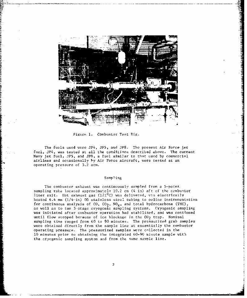
The AFAPL combustor rig used for this study (Fig. 1) consistedof a single T-56 series I combustor installed in equipment simulatingthe airflow characteristics In the actual engine. Compressors and anonvitiated heating system supplied air at appropriate temperatures,pressiures, and flow rates for the experiment.
Rather than perform the entire experiment at combustor inletconditions corresponding to T-56 engine idle, a number of temperature/pressure conditions simulating idle operation of a wide range of enginetypes were tested. Table I lists the combustor operating conditions foreach test. The lowest temperature condition tested involved 93CC inlettemperature and approximately 15 psig pressure. This corresponds toa number of Air Force engines, such as the J-85, which have overallpressure ratios. The midtemperature setting was at about 166°C, and33 psig, corresponding to the conditions of many moderate-pressureratio engines (1). Finally the high-temperature condition of 2040C and50 psig simulates many newer high-pressure-ratio engines, like theF-101 and F-100. Table 2 lists typical military engines and theirrespective idle-pressure ratios (4).
I
Figure 1. Combustor Test Rig.
The fuels used were JP4, JP5, and JPS. The present Air Force jetfuel, JP4, was tested at all the conditions described above. The currentNavy jet fuel, JP5, and JPS, a fuel similar to that used by commercialairlines and occasionally by Air Force aircraft, were tested at anoperating pressure of 3.2 atm.
Sampling
The combustor exhaust was continuously sampled from a 5-pointsampling rake located approximately 10.2 cm (4 in) aft of the cembugtor
liner exit. Hot exhaust gas (1210C) was delivered, via electricallyheated 6.4 mm (1/4-in) OD stainless steel tubing to online instrumentationfor continuous analysis of CO, C0 2 , NO., and total hydrocarbons (THC),as well as to two 3-stage cryogenic sampling systems. Cryogenic samplingwas initiated after combustor operation had stabilized, and was continueduntil flow stopped because of ice blockage in the C02 trap. Nominalsampling time ranged from 60 to 90 minutes. The pressurized grab sampleswere obtained directly from the sample line at essentially the combustoroperating pressure. The pressurized samples were collected in the10 minutes prior to obtaining the integrated 60-90 minute sample withthe cryogenic sampling system and from the same sample line.
2

TABLE 1. SINGLE-COMBUSTOR RIG OPERATING CONDITIONS
Nominal Rig Presvure Inlet Temp. Fuel/AirPower Setting _°c Wt. BASis Fuel
Preliminary 75 93 .0076 JP4
Moderate PRa 33 166 .0070 JP4Simulated idle
Low PR 15 93 *0073 JP4Simulated idle
Moderate PR 33 169 .0083 .I'5Simulated idle
High PR 50 204 .0079 iP4Simulated idle
Moderate PR 33 164 .0071Simulated idle
Moderate PR 33 166 .0072 JP8Simulated idle INo fuel flow 33(Background)
iaPressure ratio.
[i TABLE 2. AIR FORCE TURBINE ENGINES
Engne Aircraft Idle:ýpressure ratio
J-85 T-38, F-5A 1.49
J-79 F-104, F-4D, F-4E 2.55
J-57 B-52F-G, F-100, F-101, KC-135 2.60
J-52 C-9 2.80
TF-39 C-5A 3.05
T-56 C-130 3.50
TF-30 F-I11 3.56
F-101 B-I 4.0
1r-100 F-i 4.4

Tfie cryogenic sampling system is shown schematically in Figure 2.The sample gas was passed through a flow meter at 500 cc/min (measuredat 2lA10C and 760 Torr) into the first trapping cylinder (maintainedat 0 OC with ice water), through a heated inlet into the second cylinder(maintained at -780C with pulverized dry ice), throL,!. the finalcylinder (mnaintained at -1750 C with liquid nitrogen), and then exhaustedto ambient. Two unique features of the cryotrap system are the heatedinlet in the -780C trap to minimize ice formation and a gaseous nitrogenflush in the -1750C trap matrix to prevent oxygen condensation (2).
Co~oUSTOR
Er~zzL-~CeOMMt Electrical
ALTER ~ ~ ~ &II~ng Roili WTRodRYIE N OE
CM4B~ 1151
mum ~ ~ ~ IC Resistance Inut a CE PLVRZE IQI
WATER DRy ICE NITROGENA
CIVafuIC 1Bh0
Figure 2. Sampling schematic system.
4

IA
Hydrocarbon analysis of bothi tile pressurized talnk ;nd onlineIcryogenic- samples was done, WILt a coupled ga;I, chromnefograph (Varianniode]. 1400) - mass spectrometer (Dupont model 21.-491) - data (Dupont421-094i) sysroni (f1g. 1). '[ho chromatographic column packing was Porapak Q
g (120-1.50 mvsh), ill a 3-rn-lonig by 1 .6-mm-diameýter microhore (0.7 mm)stainless steel Cilme. Tb! s col umn, w! lii tempurature programming', hasprovun adrqu;~ 1w fOr scpnra LIi ng hydirocarbon compounds ranging from ethaneto CI() al iplliarkL and aromatic oxygenatesq. The chromatographlc effluentwas sp13.i t t5 o wthe chromaviog~raphiic fName ionization dletector (FID),and 75% to thev mass s;pctrometcr Hrl caýmptv enri efunentL via jet separator.I ~~C0M1)otId atinti~'t at ion Was donie I,% d igia I ntegration (Aut 01 ab TV) of the
rhiroa Ugrph-'l) r-alc ni-ca';. All puinLi tat-Ion of the FIT) was based onben -r'yesprce in. t*, r 1if' x-on u-in- (lone withI standard gas mixtures
t k•notwn, b-nii zurle conc(-r, trit ion, ciomlpolufld i denti f ication e'a done by the
>15-data 'zj -n h 00(1 eon tI (di i lilsr.r% rapF r'r racture
II
* 4
Figue 3.Laboratory -snfilv t'if-i zzsteini coupled gas
chrornatog rauhuii is' spc..tromt ter-dati systemI ~ Used for an~lVi vsu ' s ofho rOCarbon compoundsin turbineeni 'u't
5

The extremely low concentration of hydrocarbon in both cryogcnicsamples, and particularly in the grab samples, necessitated a laboratoryconcentration procedure that involved expanding the collected sample 0through a CC sample loop (2.9 ml) at liquid nitrogen temperature (-196 C).Heating the cryogenic sample bottle to a wall temperature of 150°C madethe concentration procedure more effective.
The chromatographic analysis wes done by temperature programming in0
two stages. Before injection, the gas chromatograph was cooled to -10 C.After injection, the air peaks werv- permitted to clear the column, and theoven temperature was raised to 0 , at approximately 10°/min, The gaschromatograph was then instrumentally programmed at 10°C/min to a finaltcmperature of 2500)C. A terminal isothermal hold was maintained untilno additional peaks eluted from the column. The chromatographic carriergas was helium at a flow ra e of 30 Cm3 /min. The flow rates o0 air andhydrogen were 350 and 30 cm 1min respectively.
RESULTS AND DISCISSSION
Effects of Fuel Type
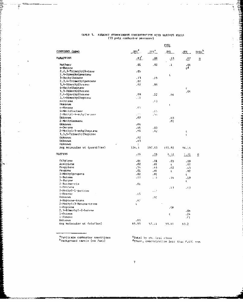
Table 3 lists the exhaust hydrocarbon concentrations detected withJP4, JP5, and JP8 fuel, at a constant inlet pressure of 33 psig.[ Between the three fuels, several differences were noted In both totalhydrocarbon content and compound distribution. Compared to JP4, thetotal concentration of exhaust hydrocarbon was greater with JP5 and JP8,which appeared to show a relationship between exhaust content and fueldensity and/or boiling range (JP5 and 6 are higher boiling and densityfuels than .TP4). The greatest amount of hydrocarbon (5.07 ppm) wasobtained with JP5, which has the highest density of the three fuels.
The qualitative differences between the fuels were primarily inthe ulefins and ketones, with jesser shifts in the paraffins, aromatics,ethers, and ,ldehydes. Overall, the olefins and ketones increased withfuel number, suggesting again a relationship between these compounds
at.d fuel density and/or boiling range. These increases in olefins andketones were offset somewhat by a decrease in the paraffin and aromaticcontent although no dramatic change occurred in the concentration of any
particular compound. The maximum concentration of both ethers andaldehydes occurred with JP5 fuel, which indicated a trend toward imcompletecombustion with the higher density fuels. The mean molecular weightshowed an increasing trend (with fuel number) for the napthenes,aromatics, and aldehydes, and no discernible difference for the othercompound classes.
6
TARLP. 3. P.XIIA11ST IWIIR(vcARMoN COIZCENTPA.Trn WITH VARIOUS FUCI
(13 psru combwstor presteurs')
COMPOUND (3p)J14 .J14, -P Jp8 .1111b
Me-Bthane .01 .02 .1 .01a
2,2 ,3-Trimettylbutarnw.01' ~2, 4-lulethylpentane Lo t
3-tMethylhexane .1 .1a7,3,4-Trimetbylpentane .02
1,~~0 .09ehylvan Z O4-Nethyiheptane I3, -Dimothvlhexaine or"2, 4-Dimothylbexane .09) .22 .0M3,4-Dlmethyiheptcine .11n-ic tane.1Uinknownn-Nnnane.4-tMethyloctane2-MletI'yl1-4-ethylIhfe ane .1; .
Unknown .07 .0312-Hethylnonane .()IUnknown .04n-tierane .04 .032-!lethyl-5-ethylhoptane 0_, Lo~
3.,5T riylen hetae L0Acetylene .02
POL yleNS .76 .76 .12 1.715
Propyne .01 .01 L.022-Methylpropere .02 .01L1-Butene .13 ILI .1o .192- Entyne2H-utene-cis .01-I-Pen te'e .3 .63
2-Met by -i--pentene1-Iloxene .15S
tlnknoown.3-Heptene-tran~s.02-Met hyl1-3-liexene- trans tI-Heptene o082, 3-ftmcthyl-2-butene .061-Oct ene t.241-Nonenle.CIUnknown .03Avg molecular wt (olefins) 65.93 52.11l 59.11 63.2
uNnlicate comibustor conditions 0 Totnl by cht:- Ical classbL.ackgronuid sendse (no fuel) dTrRCC, conc'Žntrntinn less thar .00 cnn
.7

MO7EU1,: .*0C .'n01 tdU.02)
AlI 1,~;.u .01 .01 t .02l,3-Butadit'ne t t LUnknown .09I
I -I,-,.]It. A1 I c tic- Isq
Pmg mi-!ucailar wt (dlolefinam) 59.72 54.07 54.0) 54 .06cNl.III:,I t .09ý .20 .02 3
cyc 1nhut~ne t
l,Ž-l)leIM-ilIcyrl-,ipropannm-cls tCvi olusne.19 .01
Me ty I YC (3lt!Xdlh!.07
Avg m. iit. lar wt (nnplichcnes) /0.0/ 71,4.46 98.114 105.2
A;)fI ! . .4-3 .17 .28 .10 0
Inknow i.024
Ethylbenzene .15 .061, 3-Dime-thylbenz~ný .06I1,4-f)lite thylIhcnzcne .17 1/ .1 .101 ,2-Ulmethylbcnzene .051,2,13-Trloemliylh..lnse .04n-Prcpvlhenzene .08 .04m-Fthylctuluent. .031,2,4-Trimethv~henzene 014
Avg molecuLar wt (iiromatics) 106.33 109.79 112.78 116.22 -
U.T)EHYDF.S .62 .81 2.72 1.59 0
Acctaldehyde .58 .59 2.07 1.01Acrolein .09Proplonaldelyde .02 .16 .28 .31Crotonaldehydc .05 .12Btitvraldelivde .02 .01 .14 .14
2-M. r1.vpen ..a 1.02 .08
n-IdexIil tBeoz:.l ivhvd.- t .012,4l-Di-mcthYvj~cntanaI N0Avg, nl., I i lr wt (al deltydes) 6.8.59 61.06 17.84 78.95
ALCOHOL0IS .06 .1?. .03 .33 .09
Unknow nm. 5 0
Unkzp;n tn
isooctyla Icohol .012-Plrc:'y Ilieptano] .14 .3Avg molecular wt (alcohols) 107.74 95.09 130.13 116.16
a 5Luplicnlte C~omust',r Ccci ,Iticfl5 0T'ot~a brCemical Class
biaacigroun.1 sa~mple (no Fulel) dzrnce, 'concentration lens than 0.001 nor
8

OF3
TABLE 3. (cesrl :nwi')1
COswr~rulD (pn) J1~~ a amr-
Unknown .i
ML-thylprapyll'rt.'nr
3-1Ienansc.ne .
4-Ner~hylcyr luhcxannoc J-14-Methyl-3-pent~rnc-.' .,e
Fropylbcnzy) keronte.1
Unknown ,I
Avg molecular wt (ketones) I Of. P 8 108.7 'Ii p). II III.1I1
E"THERS .'t .5 , -t
Fur an 0
3 -Mu tLtIIV I fitt a n
IsuoctyL. vinyl ether 1Avg molecular Wt (edihrs) 74;10, 'J", ? 41,' 1) 1t
ESTFRS fl.12 i ' iI
n-Amyl acetate _
Unknown%Unknown
Avg molecular wt (esterg) 171.12 7'.El
N1TR00tN-CONTAJIJINC COMPO)UNDS *t (1.0t1 I
n-Valeronttrlle LNttronzechane .111*1tImidrazole.4Avg mtolucular wt (nit rogen) 4.'72 .16 6)1 .4
HAI.OUEN-CONTAINTHC. COMPOUNDS .0)5 . 14 .01 .01 0
1-Pluorohexane .04 O
Trithlorocthvlone .0! n01 .0)I -Fluoroheptnne .1
ltnknown 6004
Unknown Oi4I- -CI lo ro-3-me thylIhutatne tv'
*AvR molecular wt CI-aiogen) Ql 7..1t70t
L-ACTONE D) 01*i ,j
B,11-Oiinechylproplolntrtone 011 .11Avg molecular wit Clactore) 100.05 100.04,
TOTAL OF ALL HYDROCARBONS 1./ 34 .27 4 .41 0.11
ra~picIIate combustor o-onrlttinns 7:Otalny tYchemical1 class!Banckvround sarnne (no f,.') ";:rncp. concentration les'- thtan 1).001 nr.a
9

Effects of Operating Pressure
Table 4 lists the exhaust hydrocarbon concentrations as a function
of combustor operating pressure for JP4 fuel. As expected, the over-whelming effect of increasing pressure was a large reduction in theexhaust toL.l hydrocarbon content (approximately 6-fold for each factorof 2.2 increase in operating pressure), This was almost certainly adirect result of improved combustion efficiency, which obtained fromincreased combustion temperature as well as operating pressure.
Although inlet pressure had a significant effect on the quantity ofexhaust hydrocarbon, there were only minor changes in exhaust quality.Ac. a percentage of tot Ll hydrocarbons, increased operating pressureresulted in increased olefinic content primarily at the expense ofparaffins. The maximum percentage of partially oxygenated speciesoccurred in the mid pressure range, from 33 to 50 psig, but was greatlyreduced ar 75 psig, reflecting the greatest degree of oxidative com-pletion. The mean molecular weight of nearly all classes of exhausthydrocarbon species tended to increase with operating pressure.
Toxicological Implicaticn.
Perhaps the most significant aspect of the data, from the toxi-cological point of view, was the large number of individual compoundsdetected in turbine engine exhaust. About 150.compounds were identified
ýa in the 8 cryogenically collected exhaust samples, with a mean of 38 com-pounds per sample. Approximately half the compounds were paraffins,Snapthenes, olefins and diolef~n!, which, in general, w,,ald be less toxicthan many of the aromatic and oxygenated species. The overall trendtoward higher molecular weight compounds and more oxygenates withincreasing fuel density portend a potentially more toxic exhaust withheavier fuels. The finding of B, B-dimethylpropiolactone in the exhaustof JP5 and JP8 was perhaps significant in that this compound is a closeanalog of B-propiolactone, one of the 13 known carcinogens restricted bythe Occupational Safety and Health Administration (6). Howeva-, detailedanalysis of the full toxicological impact of turbine engines' exhausthydrocarbon w'll have to be delayed until data from a broader spectrum ofengines and operating conditions are available.
Reproducibility
A major accomplishment of this test series was the excellc t demon-stration of reproducibility between duplicate cryogenic samples. The twosamples in question were taken at an operating pressure of 3?, "fig withJP4 fuel (Table 3). Total hydrocarbon recovety was 3.17 and 3.87 ppm,respectively. Within hydrocarbon compound classes, the concentrationreproducibility was on the average plus or minus 0.05 ppm. The totalnumber of compounds detected in the two samples was 58 and 50, respectively,with over 55% commona)ity of individual compounds.
10

TABLE 4. EXHAUST HYDROCARSON COMPOUNDS FOR JP4 FUEL AT VARIOUS VILET PRESSURES
CO1'USTOR INLET PRSSURE (pain).,P --5- __-7
o1WD (pp) 15 3a 50 75
PARAFFINS 1 1 . 8 7b .88 .83 .23 .16
methane .02 .02 .01 .01 .011,1-bidevterorhane tc
n-Butane tn-Pentane t2-Methylpentane .51 .04
2,3-Dimethylbutene .01Unknown t3-Methylpentane .062,2,3-Trimethylbutane ,n53-Methylhexane 1.22 .19 .132,3-Disothylpentene .012,3,4-Trimethylpentane .013,4-Dimethylhexane .56 .09 .022,94Oimethylhexane 1.70 .22 .09 .023.4-Dimethylheptane .]12,4,4-Tritoethylhexane .05n-Otctane 6.91 .13 .03 .012,6-Dimethylheptane .78 .02n-Nonane .84 .05 .03 .014-Methyloctane 1.01 .143-MethyloitAne
S2-Methyl-4-ethylhexane .04 .11 .023,3-Dimethylhexane .0]Unknown - .07
S2-Moethylnonane .2022 .5-Trimethylhexane .02Unknown .04n-Decane .03 .04Unknown .02-2-Methyl-5-ethylheptane .02 .043,3,i-Trimethylheptane .12 t .01Unknown .02Unknown .03Avg molecular wt (paraffins) 98.43 137.83 124.3 113.65 94.50
OLEFINS 3.80 .76 .76 .17 .28
Ethylene .24 .01 .01 .01 .01Acetylene .28 .0j .02 .05Propylene 1.35 .44 ,36 .11 .13Propyne .05 .03 .012-Nethylpropene .09 .01 .02 .01
I-Butene .60 .14 .13 .05 .082-Butyne t2-Butene-cis .01 t2-Pentene-cis .6.2-Methyl-l-pentene .121-Hexene .154-Methyl-l-Hexene .55Unknown .023-Heptene-trans .022-Methyl-3-Hexene-trans tDipentene tUnknown .03Avg molecular wt (oleftns) 52.30 52.11 65.93 65.62 44.08
8•unplicate combustor conditionsbTotal concentration by chemical class
eTra-e, concentration less than 0.001 ppr.
1M

C0O53IrSTOf IflUT PRPI~utRTr (puBg)
DOLOFgFTNS o0 5 b .01 .10 .02 P
Z.3-butatdicne t t tUnknown.01.2-Pentajdicne
t 09.02Avg molecular wt (dioieftns) 54.07 54.07 59.72 68.06 68.06NAPHIITHFjigs .53 .09 t .05 .01
Cyclobutane tIsopropYlcyclopr.)pan,e 02
1, l-DimethYleyclopropane-ci.4U~nknon~.
MelhYlcycJolhexane .53 .07 t0 0Avg molecular wt (naphthenes) 98.19 79.46 70.07 84.14 98.19
AROM~ATTCS 1.43 .37 .43 .04 .08
EthY-;)Jethle'n~e .06 .15.1,31j61.m thylbenzene - .81 .17 .17 .01
1,,ATrmehybezele.53 .04.0n-Propiy1hen7.enej - .04 .08p-Eth l! toltI ene.0.21. .
4-Trrmctuaylbenzene.0.2
Unknown .09I,-S )tc h - Athylbenzene.0Avg oleu larb n~ n wt (a o a is .02 .03.0
Av m~cu~ U (rmais) - 116.2 109.79-- 106.33 99.4 106.34ALDEHlYDES - 3.55 .81 .62 .17 .04
Acetaldehtyd.. 2.3 .59 .58 .16 .01Acrolein tProniornaidniyile .61 .16 .02 t tCrotonaldehyde .23 .05 .03 tButyraldehyde
.36 .01 .02L2-Muthylpentanal .05n-Pentanal tI
lUnknv t t.
Ben.,l. dehyd~ t .0Avg molecular wL. (alclehydes) 73.53 61.06 68.59 75.84 77.43
ALCOhWLS .43 .14. .06 0
Metthnnol t L tlinknown tPnknown .05a
UnknownmCyclohicecanemoi hanioi 02-PropVl hpptanol .14 t02-ButyI-1-c''tan.)1 .4Avg. ioleculaV WL %alco~hols) 109.;1 95.09 107.74 158.16
hDupl:chte combustor conditico1 ,;1 Talconcentrntijor bv chem~ical class
Trci, 2000nentrntiofl 'Jess t~han 0.001 non
L1

TABLE 4. (COTINUED)
COMBUSTOR TNLET PRESSURE (Peig)
COPOUND 3 15 338 335 50 75
KTONES .6 2 b .27 .22 tc t
2-Butanone .62 .09 .02 t tUnknown .01 .02Ms thylpropylketone t3-flexAnone .04Unknown t5-Mathyl-2-hexanone .10?ropylbenzylketafe .17Unknown t3-Heptanone tUnknown .04Avg moleculpar wt (ketonce) 65.07 108.59 100.88 65.07 76.09
THERS .15 .08 .05 .02 t
Puran .14 .03 .02 .022-Hethylfuran .01 t3-Methylfurar, t2,3-Epozybutane .04 .03 Lteooctyl vinyl ether .01Avg molecular wt (ethers) 75.09 94.59 74.08 68.07 72.05
ES'LERS 0 .12 0 0 .02
n-Amyl-acetate .12lteptyl formate .01Unknown .01Unknown tAvg molecular wr (esters) 130.18 212.15
NITROGEN-CONTAINING COMPOUNDS 0 0 .05 t 0
Nitromethane .01Unknown tTmidazole .04Avg molecular wt (nitrogen) 64.56 99.06
HALOGEN-CONTAINING C0OMPOUNDS .62 .34 .05 .03 t
Unknown tChloroethylene t t tI-Fluorohexane .06 .04Trichloroethylene t .01 .01 t tUnknown .03Amyl-2,2-dichloropropionate .62Unknown .04Unknown .04,l-Chloro-3-methylbutane .19Avg molecular wt (halogen) 135.31 149.97 117.75 90.63 96.95
LACTrONE 0 0 0 .01 0
2,2-Dimethylpropiolactone .01Avg molecular wt (lactone) 100.05
TOTAL HYDP.CARBON CONTENT 23.05 3.87 3.17 0.74 0.59
aDuplicate combustor conditionsbTotal concentration by chemical classCTrace. concentration less than 0.001 ppm
13

SUMMARY AND CONCLUSIONS
Cryogenic sampling was used to sample hydrocarbon exhaust from aT-56 turbine engine combustor under conditions simulating the idlepower setting of several different Air Force inventory aircraft. The pa-rameters studied were fuei type (JP4, JP5, and JP8) and combustor operatingpressure (15, 33, 50, and 75 psig). The principal conclusions from thestudy were:
1. Cryogenic sampling was an effective and reproducible techniquefor sampling gaseous hydrocarbon exhausts from turbine engines.
2. The hydrocarbon content of combustor exhaust was inverselyrelated to operating pressure.
3. The hydrocarbon content was directly related to fuel densityand/or boiling point.
4. About 150 compounds were identified; of these approximatelyhalf were aromatic and oxygenated species.
5. A trend toward higher molecular weight compounds and moreoxygenates with increasing fuel density stggested a more toxic exhaustwith heavier fuels.
6. Duplicate samples demonstrated excellent reproducibility, witha. concentration variation on the average of 0.05 ppm.
REFERENCES
1. Blazowski, W. S., and R. E. Henderson. Aircraft exhaust pollutionand its effect on the U.S. Air Force. Technical ReportAFAPL-TR-74-64, Aug 1974.
2. Conkle, J. P., J. W. Register, and G. L. Worth. Multi-stage cryogenictrapping system. Aerosp Med 36:869-874 (1965).
3. Conkle, J. P., W. W. Lackey, and R. L. Miller. Cryogenic samplingof turbine engine exhaust. SAM-TR-74-54, Nov 1974.
4. Dobbs, M. B., et al. Selected research and development projects inenvironmental quality. Technical Note AFWL-TN-74-005, Mar 1974.
5. Hertz, H. S., R. A. Hites, and K. Biemann. Identification of massspectra by computer. Searching a file of known spectra. AnalChem 43:681-691 (1971).
6. OSHA, Emergency temporary standard '.n certain carcinogens.Federal Register 38:10929, May 3, 1973.
14