ad electrical equipment vigano sezione 1 section 1 · max(mm) min.(mm) spessore thickness mm massa...
TRANSCRIPT
ADVIGANO
Explosion ProofElectrical Equipment
15
SEZIONE 1SECTION 1

TUBO RIGIDO TIPO CONDUIT IN ACCIAIO - STEEL RIGID CONDUIT
AD UNI 7683
I tubi conduit per l'infilaggio dei conduttori sono realizzati in acciaio Fe 360, galvanizzati sia all'interno sia all'esterno UNI 5745.I tubi sono generalmente forniti in barre da 6 metri, filettati maschio alle due estremità UNI 6125, completi di manicotto UNI 7683.
The rigid conduits for electric conductors are in steel Fe 360, galvanized inside and outside UNI 5745.These conduits are normally supplied in bars of commercial lengths of 6 meters, two threaded ends UNI 6125, complete with
TC1 GK ½ 21,7 21,0 2,35 1,19 45 25
TC2 GK ¾ 27,1 26,4 2,35 1,50 45 32
TC3 GK 1 34,0 33,2 2,90 2,33 60 39
TC4 GK 1 ¼ 42,7 41,9 2,90 2,99 60 48
TC5 GK 1 ½ 48,6 47,8 2,90 3,45 60 54
TC6 GK 2 60,7 59,6 3,25 4,83 60 66
TC7 GK 21/2 76,3 75,2 3,25 6,15 70 82
TC8 GK 3 89,4 87,9 3,65 8,15 70 95
CodiceCode
FilettaturaThread
Diametro esternoExternal diameter
Manicotto - Coupling UNI 7683
Max(mm) min.(mm)
SpessoreThickness
mm
Massa compresomanicotto Kg/mConduit mass
with coupling Kg/m
Diametro mmDiameter mm
Lunghezza mmLength mm
EN 50.014EN 50.018
Rs min. A min.
R C max Mn Si max P max S max2 2
N/mm kgf/mm %2 2
N/mm kgf/mm % % % % %
360÷480 37÷49 215 22 24 0,17 0,40÷0,80 0,35 0,045 0,045
Prova di trazione - Tensile test Composizione chimica - Chemical composition
Carico unitario di rottura
Unitary tensile stress
Carico unitario
di snervamento
Unitary yield load
Allungamento
Stretch
ADVIGANO
Explosion ProofElectrical Equipment
16

TUBO FLESSIBILE CONDUIT SERIE "TFFA”
MODO DI PROTEZIONE - PROTECTION MODE: II2G EEx d IIC, IP 66
I tubi flessibili sono impiegati dove non sia possibile utilizzare il tubo rigido Conduit, o per eliminare la trasmissione di vibrazioni.DATI TECNICI: tubo flessibile in acciaio inox; corrugato interno elicoidale AISI 321; rivestimento esterno AISI 304, terminali d'unione AISI 304, saldatura dei terminali in T.I.G.DETERMINAZIONE DELLA LUNGHEZZA: La lunghezza totale del flessibile deve essere espressa in millimetri (mm), includendo anche i terminali e le filettature.
FLEXIBLE CONDUIT "TFFA" SERIES
Flexible conduits are normally used in all cases where a rigid conduit is not permissible, and especially where is desired to eliminate vibration.GENERAL DATA: flexible conduit in stainless steel; internal helicoidal corrugated AISI 321;external jacketed AISI 304, terminals union AISI 304, welding of unions in T.I.G.DETERMINATION OF THE LENGTH: The total length of the flexible sheath must be expressed in millimeters (mm) and include unions and threadings.
1
2
3
4
5
6
7
8
½”
¾”
1”
1 ¼”
1 ½”
2”
2 ½”
3”
12,5
20,7
25,6
32,6
40,5
50,5
65,5
80,3
400
400
400
400
400
400
400
400
500
500
500
500
500
500
500
500
600
600
600
600
600
600
600
600
800
800
800
800
800
800
800
800
1000
1000
1000
1000
1000
1000
1000
1000
A richiesta - On request
A richiesta - On request
A richiesta - On request
A richiesta - On request
A richiesta - On request
A richiesta - On request
A richiesta - On request
A richiesta - On request
N° Ø D Ø dL = Lunghezza in mm - Length in mm
Standard Altre - More
LEGENDA - WHERE:L = Lunghezza totale del flessibile in mm - Total length of the flexible coupling in mmN° = Numerazione convenzionale - Conventional numerationØ D = Diametro filettatura UNI 6125 - Thread diameter UNI 6125Ø d = Diametro utile interno in mm - Useful internal diameter in mm
ØD
L
Ød
TFFA … / …
Tubo flessibile con terminali maschio-maschioFlexible conduit with unions male-male
Lunghezza in mm - Length in mmDiametro nominale in base alla numerazione convenzionaleNom. Diam. According to conventional numeration
ADVIGANO
Explosion ProofElectrical Equipment
EN 50.014EN 50.018ATEX 94/9/CE
Identificazione della costruzioneDentification of the construction
17
ILLUSTRAZIONI - ILLUSTRATIONSD
D
D
D
d
d
d
d
¾”
¾”
¾”
¾”
3/4”1”
11/4”11/2”
2”21/2”
3”
3/4”1”
11/4”11/2”
2”21/2”
3”
3/4”1”
11/4”11/2”
2”21/2”
3”
3/4”1”
11/4”11/2”
2”21/2”
3”
RE21RE31RE41RE51RE61RE71RE81
REB21REB31REB41REB51REB61REB71REB81
REM21REM31REM41REM51REM61REM71REM81
REN21REN31REN41REN51REN61REN71REN81
RE32RE42RE52RE62RE72RE82
REB32REB42REB52REB62REB72REB82
REM32REM42REM52REM62REM72REM82
REN32REN42REN52REN62REN72REN82
RE43RE53RE63RE73RE83
REB43REB53REB63REB73REB83
REM43REM53REM63REM73REM83
REN43REN53REN63REN73REN83
RE54RE64RE74RE84
REB54REB64REB74REB84
REM54REM64REM74REM84
REN54REN64REN74REN84
RE65RE75RE85
REB65REB75REB85
REM65REM75REM85
REN65REN75REN85
RE76RE86
REB76REB86
REM76REM86
REN76REN86
RE87
REB87
REM87
REN87
½”
½”
½”
½”
1”
1”
1”
1”
11/4”
11/4”
11/4”
11/4”
11/2”
11/2”
11/2”
11/2”
2”
2”
2”
2”
21/2”
21/2”
21/2”
21/2”
ILLUSTRAZIONI - ILLUSTRATIONS
ILLUSTRAZION - ILLUSTRATIONSI
ILLUSTRAZIONI - ILLUSTRATIONS
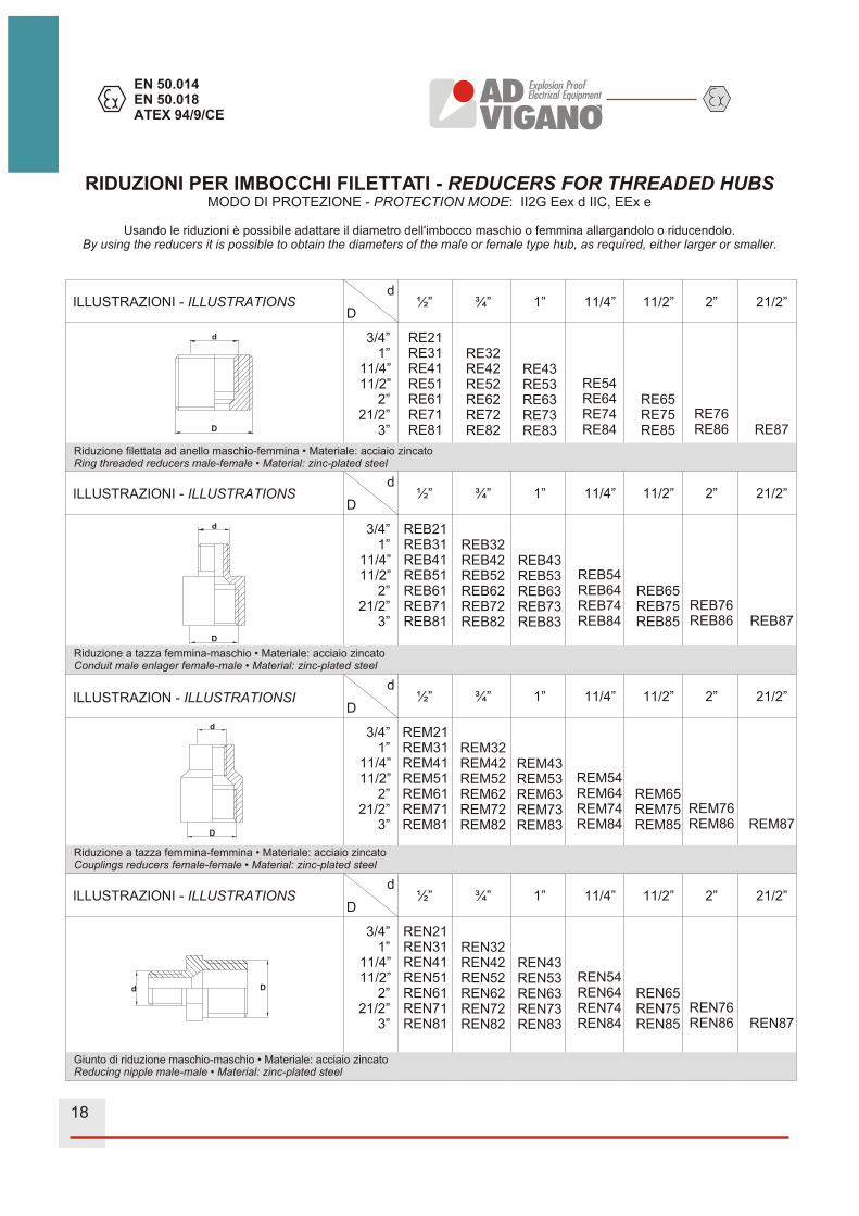
Riduzione a tazza femmina-maschio • Materiale: acciaio zincatoConduit male enlager female-male • Material: zinc-plated steel
Riduzione a tazza femmina-femmina • Materiale: acciaio zincato•Couplings reducers female-female Material: zinc-plated steel
Giunto di riduzione maschio-maschio • Materiale: acciaio zincatoReducing nipple male-male • Material: zinc-plated steel
RIDUZIONI PER IMBOCCHI FILETTATI - MODO DI PROTEZIONE - PROTECTION MODE: II2G Eex d IIC, EEx e
Usando le riduzioni è possibile adattare il diametro dell'imbocco maschio o femmina allargandolo o riducendolo.
REDUCERS FOR THREADED HUBS
By using the reducers it is possible to obtain the diameters of the male or female type hub, as required, either larger or smaller.
d
D
d
D
d
D
d D
Riduzione filettata ad anello maschio-femmina • Materiale: acciaio zincatoRing threaded reducers male-female • Material: zinc-plated steel
ADVIGANO
Explosion ProofElectrical Equipment
EN 50.014EN 50.018ATEX 94/9/CE
18

½”
¾”
1”
1 ¼”
1 ½”
2”
2 ½”
3”
4”
½”
¾”
1”
1 ¼”
1 ½”
2”
2 ½”
3”
4”
½”
¾”
1”
1 ¼”
1 ½”
2”
2 ½”
3”
4”
5”
NP 1
NP 2
NP 3
NP 4
NP 5
NP 6
NP 7
NP 8
NP 10
PLG 1
PLG 2
PLG 3
PLG 4
PLG 5
PLG 6
PLG 7
PLG 8
PLG 10
DB 1
DB 2
DB 3
DB 4
DB 5
DB 6
DB 7
DB 8
DB 10
DB 12
55
55
65
65
65
65
85
85
85
13
17
19
24
30
36
55
65
85
0,012
0,014
0,020
0,025
0,032
0,046
0,062
0,071
0,107
0,134
0,045
0,060
0,090
0,125
0,135
0,170
0,555
0,720
1,190
20
20
23
26
26
26
30
30
30
0,03
0,06
0,12
0,21
0,27
0,52
0,66
0,90
-
A richiestaOn request
½”
¾”
1”
1 ¼”
1 ½”
2”
2 ½”
3”
4”
½”
¾”
1”
1 ¼”
1 ½”
2”
2 ½”
3”
4”
½”
¾”
1”
1 ¼”
1 ½”
2”
2 ½”
3”
4”
5”
EM 1
EM 2
EM 3
EM 4
EM 5
EM 6
EM 7
EM 8
EM 10
DL 1
DL 2
DL 3
DL 4
DL 5
DL 6
DL 7
DL 8
DL 10
DBT 1
DBT 2
DBT 3
DBT 4
DBT 5
DBT 6
DBT 7
DBT 8
DBT 10
DBT 12
45
45
55
60
60
60
70
70
70
6
6
6
7
7
7
18
20
22
0,016
0,018
0,024
0,033
0,040
0,054
0,070
0,079
0,115
0,142
0,065
0,076
0,127
0,283
0,315
0,630
0,663
0,775
1,015
0,015
0,02
0,02
0,06
0,06
0,07
0,08
0,13
0,18
M5
M5
M5
M6
M6
M6
M6
M6
M6
M6
GIUNTI SERIE NPNIPPLES NP SERIES
MODO DI PROTEZIONEPROTECTION MODE
II2G Eex d IIC, EEx e II
Materiale: acciaio zincato - Material: zinc-plated steel Diametro Nom.Nom. Diameter
Diametro Nom.Nom. Diameter
Diametro Nom.Nom. Diameter
CodiceCode
CodiceCode
CodiceCode
Hmm
Cmm
Hmm
Peso - WeightKg
Peso - WeightKg
Peso - WeightKg
Peso - WeightKg
Peso - WeightKg
Diametro dadoBolt diam.
Peso - WeightKg
Diametro Nom.Nom. Diameter
Diametro Nom.Nom. Diameter
Diametro Nom.Nom. Diameter
CodiceCode
CodiceCode
CodiceCode
Hmm
Hmm
Materiale: acciaio zincato o alluminio - Material: zinc-plated steel or aluminum
Materiale: alluminio - Material: aluminum
Materiale: acciaio zincato - Material: zinc-plated steel
Materiale: acciaio zincato o alluminio - Material: zinc-plated steel or aluminum
Materiale: alluminio - Material: aluminum
TAPPO SERIE PLGPLUG PLG SERIES
MODO DI PROTEZIONEPROTECTION MODE
II2G Eex d IIC, EEx e II
TERMINALI SERIE DBBUSHINGS DB SERIES
MANICOTTI SERIE EMCOUPLINGS EM SERIES
MODO DI PROTEZIONEPROTECTION MODE
II2G Eex d IIC, EEx e II
DADO SERIE DNUT DL SERIESL
TERMINALI SERIE DBTBUSHINGS DBT SERIES
ACCESSORI PER TUBO CONDUIT - ACCESSORIES FOR CONDUITS
H
H H
HADVIGANO
Explosion ProofElectrical Equipment
EN 50.014EN 50.018ATEX 94/9/CE
19

A
D
A
D
A
D
ILLUSTRAZIONE - ILLUSTRATIONSCodiceCode
BMF 1
BMF 2
BMF 3
BMF 4
BMF 5
BMF 6
BMF 7
BMF 8
½”
¾”
1”
1 ¼”
1 ½”
2”
2 ½”
3”
½”
¾”
1”
1 ¼”
1 ½”
2”
2 ½”
3”
½”
¾”
1”
1 ¼”
1 ½”
2”
2 ½”
3”
63
62
70
80
85
88
100
100
48
48
50
56
62
68
68
73
80
80
94
102
104
104
123
133
34
40
46
61
70
82
105
122
34
40
46
61
70
82
105
122
34
40
46
67
78
93
116
133
Filettaturamaschio fissa
e femmina girevole
With threads fixed male and
revolving female
Filettatura girevolefemmina-femmina
With threads fixed female andrevolving female
Filettatura girevole maschio-maschio
With threads fixed male andrevolving male
BFF 1
BFF 2
BFF 3
BFF 4
BFF 5
BFF 6
BFF 7
BFF 8
BMM 1
BMM 2
BMM 3
BMM 4
BMM 5
BMM 6
BMM7
BMM 8
ØDimensioni - Dimensions mm
A DCaratteristicheCharacteristics
GIUNTI DI COLLEGAMENTO A TRE PEZZI - THREE PIECE CONNECTION FITTINGS
MODO DI PROTEZIONE - PROTECTION MODE: EEx d IIB-IIC
Nota: per ordinare l’esecuzione IIC sostituire la prima lettera del codice con la lettera R esempio BMM 1 - RMM 1
Note: to order the execution IIC to replace the first letter of the code with the letter R example: BMM 1 - RMM 1
ADVIGANO
Explosion ProofElectrical Equipment
EN 50.014EN 50.018ATEX 94/9/CE
20

CURVE SERIE “EL” - ELBOWS “EL..” SERIES
SERIE ELF Femmina • Femmina - ELF SERIES Female • Female
½”
¾”
1”
1 ¼”
1 ½”
2”
2 ½”
3”
½”
¾”
1”
1 ¼”
1 ½”
2”
2 ½”
3”
½”
¾”
1”
1 ¼”
1 ½”
2”
2 ½”
3”
ELF 1
ELF 2
ELF 3
ELF 4
ELF 5
ELF 6
ELF 7
ELF 8
ELFM 1
ELFM 2
ELFM 3
ELFM 4
ELFM 5
ELFM 6
ELFM 7
ELFM 8
ELM 1
ELM 2
ELM 3
ELM 4
ELM 5
ELM 6
ELM 7
ELM 8
57
57
70
85
85
100
115
135
72
72
92
112
112
135
157
185
30
30
35
50
50
60
65
80
0,125
0,100
0,200
0,395
0,370
0,625
0,880
1,480
0,170
0,180
0,290
0,520
0,505
0,795
1,435
2,200
0,170
0,180
0,290
0,520
0,505
0,795
1,435
2,200
Materiale: lega leggera di alluminioMaterial: light aluminum alloy
Materiale: lega leggera di alluminioMaterial: light aluminum alloy
Materiale: lega leggera di alluminioMaterial: light aluminum alloy
Diam. Nom.Nom. Diam.
Diam. Nom.Nom. Diam.
Diam. Nom.Nom. Diam.
CodiceCode
CodiceCode
CodiceCode
Amm
Hmm
Rmm
Peso KgWeight Kg
Peso KgWeight Kg
Peso KgWeight Kg
SERIE ELFM Maschio • Femmina - ELFM SERIES Male • Female
SERIE ELM Maschio • Maschio - ELM SERIES Male • Male
H
A
R
ADVIGANO
Explosion ProofElectrical Equipment
EN 50.014EN 50.018ATEX 94/9/CE
MODO DI PROTEZIONE - PROTECTION MODE: EEx d IIC
21

SISTEMI DI FISSAGGIO PER TUBO CONDUITCLAMP FOR CONDUIT
ILLUSTRAZIONIILLUSTRATIONS
CODICECODE
SERIESERIES
GF 1
GF 2
GF 3
GF 4
GF 5
GF 6
GF 7
GF 8
GH 1
GH 2
GH 3
GH 4
GH 5
GH 6
GH 7
GH 8
MT 1
MT 2
MT 3
MT 4
MT 5
MT 6
MT 7
MT 8
Ø 7
Ø 7
Ø 7
Ø 9
Ø 9
Ø 9
Ø 11
Ø 11
M 6
M 6
M 6
M 6
M 8
M 8
M 8
M 8
M 6
M 6
M 6
M 6
M 8
M 8
M 8
M 8
½”
¾”
1”
1 ¼”
1 ½”
2”
2 ½”
3”
½”
¾”
1”
1 ¼”
1 ½”
2”
2 ½”
3”
½”
¾”
1”
1 ¼”
1 ½”
2”
2 ½”
3”
GF
GH
MT
ØNom.
ØForo o dado
Hole orbolt
CARATTERISTICHECHARACTERISTICS
NOTENOTES
Collare in lamiera stampata.A richiesta possono essere fornite con zanca o con bullone aggiungendo la siglaZ o B al Codice.Sheet steel clamps for fixing conduit.On request can be supplied with anchorbolt or with boltAdding Z or B to Cat. N°.
Cavallotti ad U completi dibulloni, rondelle pianee grover, per il montaggio di tubi portacavi direttamentesu profilati mediante foraturadegli stessi.U bolts with nutsand washerfor directly attaching conduitto steel frameworks makingfixing holes.
Materiale:acciaio zincatoMaterial:zinc-plate steel
Materiale:acciaio zincatoMaterial:zinc-plate steel
Le staffe della serie MT,sono ideali per ilfissaggio perpendicolare del tubo portacavi alla struttura portante.The clamp of the MT series,are suitable for a perpendicular attachment of the conduit to the support structure.
Materiale:acciaio zincatoMaterial:zinc-plate steel
Collare in fusione di alluminio
A richiesta:GF 10 ø 4"GF 12 ø 5”
ADVIGANO
Explosion ProofElectrical Equipment
22

ADVIGANO
Explosion ProofElectrical Equipment
EN 50.014EN 50.018ATEX 94/9/CE
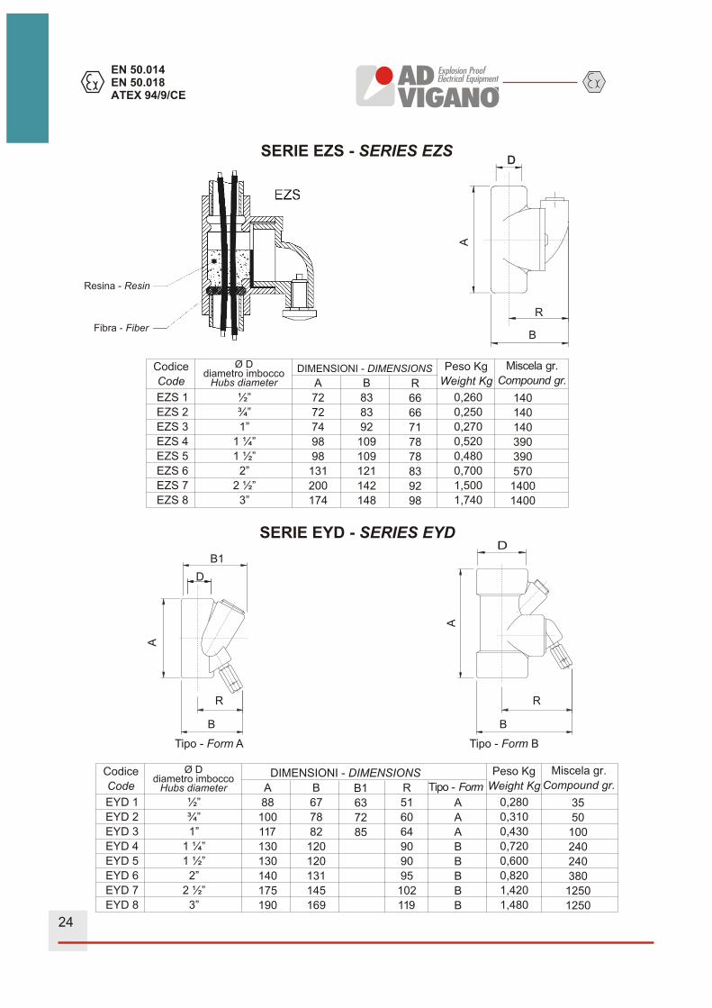
RACCORDI DI BLOCCAGGIO SERIE “EYS - EZS - EYD”SEALING FITTINGS SERIES “EYS - EZS - EYD”
MODO DI PROTEZIONE - PROTECTION MODE: II 2 GD EEx d IIC
Raccordi di bloccaggio in fusione di lega leggera, con apertura laterale per l’inserimento della resina di bloccaggio.Vengono impiegati per il sezionamento dei tubi portacavi ed impedire il propagarsi di eventuali esplosioni. Vengonorealizzati sia per l’inserimento in verticale (EYS) che orizzontale (EZS). I raccordi EZD vengono installati sulla base di un tubo Conduit verticale di altezza notevole in quanto oltre a bloccare,drenano l’eventuale acqua che si sia accumulata sulla superficie della miscela di bloccaggio.
Fitting in cast light alloy with side opening for sealing with special compound.Used for sectioning of conduit and to prevent eventual explosion spreading. Manufactured for vertical (EYS) or horizontal(EZS)The EZD type fittings are installed on the base of the vertical conduit coming from a high height, so that as well as sealingthey drain any eventual water which may accumulate on the surface of the solidified compound.
NOTA: Con il raccordo di bloccaggio è obligatorio acquistare la miscela CRV420.
NOTE: With sealing fitting it is obligatory to purchase the compound type CRV420.
SERIE EYS - SERIES EYS
EYS 1
EYS 2
EYS 3
EYS 4
EYS 5
EYS 6
EYS 7
EYS 8
½”
¾”
1”
1 ¼”
1 ½”
2”
2 ½”
3”
A
77
88
106
146
131
141
194
190
B
60
68
84
82
87
100
124
138
R
44
51
62
51
58
63
78
85
TIPO-FORM
A
A
A
B
B
B
B
B
0,130
0,190
0,320
0,600
0,470
0,650
1,260
1,330
35
50
100
240
240
380
1250
1250
Codice
Code
Ø Ddiametro imbocco
Hubs diameter
DIMENSIONI - DIMENSIONS Peso Kg
Weight Kg
Miscela gr.
Compound gr.
Ø D
R
A
B
TIPO - FORM: AEYS 1-2-3
TIPO - FORM: BEYS 4-5-6-7-8
Ø D
R
A
B
Resina - Resin
Fibra - Fiber
23
EN 50.014
EN 50.018
ATEX 94/9/CE
ADVIGANO
Explosion ProofElectrical Equipment
SERIE EZS - SERIES EZS
SERIE EYD - SERIES EYD
Tipo - Form A
R
B
A
B1
D
Tipo - Form B
R
B
A
D
R
A
B
EZS 1
EZS 2
EZS 3
EZS 4
EZS 5
EZS 6
EZS 7
EZS 8
½”
¾”
1”
1 ¼”
1 ½”
2”
2 ½”
3”
A
72
72
74
98
98
131
200
174
B
83
83
92
109
109
121
142
148
R
66
66
71
78
78
83
92
98
0,260
0,250
0,270
0,520
0,480
0,700
1,500
1,740
Codice
CodeDIMENSIONI - DIMENSIONS Peso Kg
Weight Kg
140
140
140
390
390
570
1400
1400
Miscela gr.
Compound gr.
Ø Ddiametro imbocco
Hubs diameter
EYD 1
EYD 2
EYD 3
EYD 4
EYD 5
EYD 6
EYD 7
EYD 8
½”
¾”
1”
1 ¼”
1 ½”
2”
2 ½”
3”
A
88
100
117
130
130
140
175
190
B
67
78
82
120
120
131
145
169
R
51
60
64
90
90
95
102
119
B1
63
72
85
A
A
A
B
B
B
B
B
0,280
0,310
0,430
0,720
0,600
0,820
1,420
1,480
Codice
CodeDIMENSIONI - DIMENSIONS Peso Kg
Weight Kg
35
50
100
240
240
380
1250
1250
Miscela gr.
Compound gr.
Ø Ddiametro imbocco
Hubs diameter Tipo - Form
Resina - Resin
Fibra - Fiber
24

ADVIGANO
Explosion ProofElectrical Equipment
MISCELA DI BLOCCAGGIO SERIE - SEALING COMPOUND SERIES“CRV420”
La miscela di bloccaggio CRV420 è costituita da una resina epossidica, particolarmente studiata per la miscelazione dei giunti di bloccaggio antideflagranti.
CARATTERISTICHE:
- Alta resistenza alle sollecitazioni dinamiche.- Perfetta tenuta ermetica alle infiltrazioni di gas o vapori pericolosi.- Ottima resistenza alle alte temperature (> 200°C)- Massima penetrazione, fluidità e facilità di preparazione- Stabilità fisica e chimica- Rigidità dielettrica superiore a quella degli stessi conduttori
I componenti della miscela sono forniti così confezionati:Resina confezioni da 100, 300, 400 e 1000 gr.Indurente confezioni da 25, 75, 100 e 250 gr.
CARATTERISTICHE TECNICHE:
Rapporto di miscelazione 100 gr. Resina con 25 gr. Indurente.
Tempo di utilizzo:- Temperatura ambiente di 20°C entro 3 0 minuti dalla miscelazione- Temperatura ambiente di 15°C entro 4 5 minuti dalla miscelazione
Tempo d’indurimento 4 ore
Tempo di catalizzazione 24 ore
ISTRUZIONI PER L'USO:
Predisporre sul fondo del raccordo di bloccaggio, la fibretta disponendola bene intorno e tra i conduttori per evitare che la miscela scenda nel tubo conduit.Versare una parte del componente A (resina) in un contenitore metallico o plastico privo di impuritàAggiungere il componente B (indurente), mantenendo sempre il rapporto di miscelazione in peso o percentuale mescolare il composto fino a renderlo omogeneo colare il composto nel raccordo precedentemente preparato.
The sealing compound consists in an epoxy resin especially studied for a mixture of explosion-proof sealing fittings.
CHARACTERISTICS:
High resistance to dynamic stresses.Perfect seal against infiltrations of dangerous gases or vapours.
Excellent resistance to temperatures (> 0°CMaximum penetration, fluidity and facility of preparationPhysical and chemical stabilityDielectric strength higher than that of the conductors themselves
The compound components are normally supplied as follows:Container with 100, 300, 400 and 1000 grams of component A (resin).Container with 25, 75, 100 and 250 grams of component B (hardener).
TECNICAL DATA:
Mixing ratio 100 gr. of resin with 25 gr. of hardener
Time of use:--Room temperature equal t o 20°C within 3 0 minutes from stirring up -Room temperature of 15°C within 4 5 minutes from stirring up.
Hardening time around 4 hours.
Cathalizing time 2 4 hours.
DIRECTIONS FOR USE:
Insert the fiber on the bottom of the sealing fitting, you place the fiber between the conductors and conduit.Pour a part of component A (resin) into a metallicor plastic container frre o f impuritiesAdd on the component B (hardener), by always keeping the correct mixing ratio of weight or percentageStirr the compound for as much as t o make i t homogeneousLet the substance glue down on the previously prepared connection.
25


PRESSACAVI “EEx d, EEx e, EEx i” PER CAVI NON ARMATI SERIE FGF
“EEx d” CABLE GLANDS FOR NOT ARMOURED CABLES SERIES "PAPF...0” AND FGF...0”
MODO DI PROTEZIONE - PROTECTION MODE: EEx d IIB-IIC, EEx e, EEx i IP66/67
CONDIZIONI D’IMPIEGO: In area esplosiva gruppo II zone 1-2-21-22, sono utilizzati per la sigillatura di cavi non armati, i pressacavi presentano un’imbocco filettato femmina che permette la connessione di un tubo conduit o di un flessible.FILETTATURA: Standard GK UNI 6125 A richiesta NPT ANSI B2.1 - GAS UNI 338 - PG DIN 40430 ISO Metrica passo 1,5MATERIALI: Acciaio zincato standard A richiesta indicare dopo il codice: /A = alluminio UNI 3571, /O = ottone nichelato OT 58, /X = acciaio inox316
OPERATING CONDITIONS: Dangerous area cl. 1 zones 1-2-21-22 indoor high humidity, dusts and oil and/or outdoor rain exposed. Are used for sealing an unarmoured cable, with the possibility of external connection to a conduit tube or a flexible. THREAD: Standard GK UNI 6125. On request NPT ANSI B2.1 - GAS UNI 338 - PG DIN 40430 ISO Metric pitch 1,5MATERIALS: Standard zinc-plated steel . On request use: A = light alloy UNI 3571, O = nickel-plated brass OT 58, X = stainless steel 316
FGF 1 A1
FGF 1 B1
FGF 2 B2
FGF 2 C2
FGF 3 A3
FGF 3 B3
FGF 4 A4
FGF 4 B4
FGF 5 A5
FGF 5 B5
FGF 6 A6
FGF 6 B6
FGF 6 C6
FGF 7 A7
FGF 7 B7
FGF 7 C7
FGF 7 D7
FGF 8 C8
FGF 8 D8
FGF 8 E8
6
9
11
14
17
20
23
26
29
32
36
39
42
44
48
52
56
59
63
67
9
12
14
17
20
23
26
29
32
36
39
42
46
48
52
56
60
63
67
71
½” 30
C
CODICE
CODE
Dimensione esterna cavo
Cable external dimensions
Dimensioni pressacavoCable Gland dimensions
Ø
35
DØ min
70
HØ max
¾” 35 40 70
1” 42 48 85
1 ¼” 56 66 89
1 ½” 70 75 96
2” 84 90 96
2 ½” 108 117 108
3” 121 132 108
Testa StringicavoGland nut
Corpo inferioreInferior body
Gommino di tenuta in neoprene “EEx d” e “w.p.”“EEx d” and “w.p.” neoprene seal
Anello premigomminoSkid washer
D
HC
ADVIGANO
Explosion ProofElectrical Equipment
EN 50.014
EN 50.018
ATEX 94/9/CE
28

PRESSACAVI “EEx d, EEx e, EEx i” PER CAVI NON ARMATI SINGOLA TENUTA SERIE FG“EEx d” CABLE GLANDS FOR CABLES NOT ARMOURED SERIES "PAP...1” AND FG...1"
MODO DI PROTEZIONE - PROTECTION MODE: EEx d IIB-IIC, EEx e, EEx i IP 66
CONDIZIONI D’IMPIEGO: aree esplosive gruppo II zone 1-2-21-22, sono utilizzati per la sigillatura di cavi non armati. FILETTATURA: Standard GK UNI 6125 A richiesta NPT ANSI B2.1 - GAS UNI 338 - PG DIN 40430 ISO Metrica passo 1,5MATERIALI:Acciaio zincato standard A richiesta indicare dopo il codice: A = alluminio UNI 3571, /O = ottone nichelato OT 58, /X = acciaio inox 316
OPERATING CONDITIONS: Dangerous area cl. 1 zones 1-2-21-22 indoor high humidity, dusts and oil and/or outdoor rain exposed. Seal on the internal cable insulation under armour.THREAD: Standard GK UNI 6125. On request NPT ANSI B2.1 - GAS UNI 338 - PG DIN 40430 ISO Metric pitch 1,5MATERIALS: Standard zinc-plated steel. On request use: A = light alloy UNI 3571, O = nickel-plated brass OT 58, X = stainless steel 316
Testa Stringicavo - Gland nut
Corpo inferiore - Inferior body
Gommino di tenuta in neoprene “EEx d” e “w.p.” Sottoarmatura“EEx d” and “w.p.” underarmour neoprene seal
Anello premigommino - Skid washer
H
ØD
C
FG 1 A1
FG 1 B1
FG 2 B2
FG 2 C2
FG 3 A3
FG 3 B3
FG 4 A4
FG 4 B4
FG 5 A5
FG 5 B5
FG 6 A6
FG 6 B6
FG 6 C6
FG 7 A7
FG 7 B7
FG 7 C7
FG 7 D7
FG 8 C8
FG 8 D8
FG 8 E8
6
9
11
14
17
20
23
26
29
32
36
39
42
44
48
52
56
59
63
67
9
12
14
17
20
23
26
29
32
36
39
42
46
48
52
56
60
63
67
71
½” 30
CØ
35
DØ min
55
HØ max
¾” 35 40 55
1” 42 48 66
1 ¼” 50 59 68
1 ½” 60 68 68
2” 74 84 68
2 ½” 90 94 76
3” 110 115 76
CODICE
CODE
Dimensione esterna cavo
Cable external dimensions
Dimensioni pressacavoCable Gland dimensions
ADVIGANO
Explosion ProofElectrical Equipment
EN 50.014
EN 50.018
ATEX 94/9/CE
29

PRESSACAVO “EEx d, EEx e, EEx i”
PER CAVO ARMATO A DOPPIA TENUTA SERIE FGA
“EEx d, EEx e, EEx i” CABLE GLANDS FOR DOUBLE SEAL ARMOURED
CABLES SERIES FGA
MODO DI PROTEZIONE - PROTECTION MODE: EEx d IIB-IIC, EEx e, EEx i Ip66
CONDIZIONI D’IMPIEGO : aree esplosive gruppo II zone 1-2-21-22, sono utilizzati per la sigillatura della guaina isolante interna ed esterna e il serraggio dell’armatura.
FILETTATURA: Standard GK UNI 6125. A richiesta NPT ANSI B2.1 - GAS UNI 338 - PG DIN 40430 ISO Metrica passo 1,5
MATERIALI: Acciaio zincato standardA richiesta usare: A= alluminio UNI 3571, O = ottone nichelato OT 58, X = acciaio inox 316
OPERATING CONDITIONS: Dangerous area cl. 1 zones 1-2-21-22 indoor high humidity, dusts and oil and/or outdoor rain exposed. Seal on the internal cable insulation under armour.
THREAD: Standard GK UNI 6125. On request NPT ANSI B2.1 - GAS UNI 338 - PG DIN 40430 ISO Metric pitch 1,5
MATERIALS: Standard zinc-plated steel On request use: A= light alloy UNI 3571, O = nickel-plated brass OT 58, X = stainless steel 316
Testa StringicavoGland nut
Corpo inferioreInferior body
Corpo IntermedioMiddle body Cono blocca armatura
Armour clamping cone
Ghiera blocca armaturaArmour clamping ring
Gommino di tenuta in neoprene “EEx d” e “w.p.”“Eex d” and “w.p.” underarmour neoprene seal
Gommino tenuta esternoOuter neoprene seal
ADVIGANO
Explosion ProofElectrical Equipment
EN 50.014
EN 50.018
ATEX 94/9/CE
30


ADVIGANO
Explosion ProofElectrical Equipment
EN 50.014
EN 50.018
ATEX 94/9/CE
M
H
d D S
AC AC1 AC2
Miscela di BloccaggioSealing Mixture
Tipopressacavo
PesoKg
Campo d’impiego del pressacavoRange of the cable gland
Dimensioni d’ingombroOverall dimensions
Spessorearmaturamin-max
GrandezzaSize
Cable glandtype
Weightin Kg
Sheaththicknessmin-max
FGABEGAB
FGABEGAB
FGABEGAB
FGABEGAB
FGABEGAB
FGABEGAB
FGABEGAB
FGABEGAB
1 (1/2”)
M
2 (3/4”)
3 (1”)
4 (11/4”)
5 (11/2”)
6 (2”)
7 (21/2”)
8 (3”)
83
H
35
S
27
AC
30
AC1
27
AC2
8-18
Dmin-max
dmin-max
RangegomminiRange
sealing rings
SiglagomminiRef.Codesealingrings
5-13 0,220 0,5-1,48-11
11-1414-18
a2b2c2
17-2020-2323-25
a3b3c3
23-2626-2929-32
a4b4c4
29-3232-3636-39
a5b5c5
36-3939-4242-4444-46
a6b6c6d6
44-4848-5252-5656-60
a7b7c7d7
51-5555-5959-6363-6767-70
a8b8c8d8e8
65-6969-7373-7777-8181-84
a9b9c9d9e9
83 40 32 35 32 17-25 11-18 0,250 0,5-1,8
95 48 40 42 40 23-32 17-24 0,380 0,5-2,0
100 69 53 60 50 29-39 23-30 0,660 0,9-2,0
100 77 60 67 55 36-46 29-38 0,680 1,2-2,5
100 90 72 78 72 44-60 36-49 1,190 1,3-2,5
110 121 95 105 82 51-70 44-61 1,520 1,3-2,5
110 133 105 115 103 65-84 59-74 2,250 1,5-3,2
32
PRESSACAVI BARRIERA PER CAVI ARMATI SERIE “FGAB”
BARRIER CABLE GLANDS FOR ARMOURED CABLE SERIES “FGAB”
MODO DI PROTEZIONE - PROTECTION MODE: EEx d IIC, EEx e, EEx i IP 66/67
CONDIZIONI D’IMPIEGO: aree esplosive gruppo II zona, 1-2-21-22, sono utilizzati per la sigillatura di cavi non armati.
OPERATING CONDITIONS: Dangerous area group II, zone 1-2-21-22, indoor high humidity, dusts and oil and/or outdoor rain exposed. Seal on the internal cable insulation under armour.
FILETTATURA: Standard GK UNI 6125 altre filettature a richiesta.THREAD: Standard GK UNI 6125 other threads on request
MATERIALI: Acciaio zincato standard A richiesta indicare dopo il codice: /A = alluminio UNI 3571, /O = ottone nichelato OT 58, /X = acciaio inox AISI 304, a richiesta 316L
MATERIALS: Standard zinc-plated steel On request use: /A = light alloy UNI 3571, /O = nickel-plated brass OT 58, /X = stainless steel AISI 304 on request 316L
Inoltre fornisce un'ulteriore protezione, grazie alla particolare boccola che, riempita con l'apposita miscela di bloccaggio, impedisce la propagazione della fiamma.
But this type of cables provides a further protection thanks to the particular ring that filled with the special sealing mixture, prevents the flame propagation.
NOTA: sono disponibili altre versioni di pressacavo barriera, per cavo non armato e con imbocco filettato maschio o femmina in uscita.
NOTE: it’s availlable other type of barrier cable glands, for unarmoured cable and with male or female threaded cable outlet.

ADVIGANO
Explosion ProofElectrical Equipment
SCELTA DEI DISPOSITIVI DI ENTRATA CAVO IN CUSTODIE A PROVA DI ESPLOSIONE
SELECTION CHART FOR CABLE ENTRY DEVICES INTO FLAME-PROOF ENCLOSURES
INIZIOSTART
Questa custodia contiene una sorgente di
accensione ?
Does this enclosure contain an internal source of ignition ?
(vedi nota / see note)
Nota:
Le sorgenti di accensione interne possono essere costituite da scintille e t e m p e r a t u r e e l e v a t e d e l l ’ a p p a r e c c h i a t u r a , c h e i n funzionamento normale possono causare l’accensione. Una custodia contenente solo terminali o una custodia con ingresso indiretto non sono considerate sorgenti di accensione interne.
Note:
Internal source of ignition include sparks or equipment temperatures occurring in normal operation which can cause ignition. An enclosure containing terminals only or an indirect entry enclosure is considered not to constitute an internal source of ignition.
Il volume della custodia è 3
superiore a 2 dm ?
Is the volume of the enclosure 3
greater then 2 dm ?
Il gas pericoloso richiede una costruzione IIC ?
Does the hazardus gas require IIC apparatus ?
Il luogo di destinazione è zona 1 ?
Is the area of installation zone 1 ?
Usare un dispositivo di entrata cavo a prova di
esplosionecon sigillatura dei singoli
conduttori interni.
Use a flame-proof cable entry device with
compound which permit stopping around individuals cores.
Usare un idoneo dispositivo di entrata del
cavo a prova d’esplosione con anello di tenuta elastomerico
Use a suitable flame-proof cable entry device
with a elastomeric sealing ring
SIYES
SIYES
SIYES
SIYES
NO
NO
NO
NO
33

≥
Colour code cores
in conformity with
CEI-UNEL 00722-00725
Conductors
Insulation
Inner sheat
Armouring
Outer sheat
Working voltage
Testing voltage
Working temperature
Outer printing
Bending radius
n° 2 blue, black
n° 3 blue, brown, yellowgreen
n° 4 blue, brown, black, yellowgreen
n° 5 blue, brown, black, yellowgreen, black
n° >5 black white numbered with yellowgreen
fine stranded wires of bare copper class 5
HEPR compound type G7
P.V.C. compound fire retardant
galvanized steel wires braid coverage 80%
Grey P.V.C. compound type Rz
0,6/1 kV
4 kV
-15 °C ÷ +90 °C
AD Viganò FG7ORAR<n° conductors/G section>0,6/1kV CEI 20-22 II
Cable outer diameter x 8
TECHNICAL FEATURES
NORMATIVE REFERENCE
Conductor
Insulation and sheath
No flame propagation
No fire propagation
Controlled discharge of corrosive gas in case of fire
Rubber insulated cables with rated voltage between 1 kV and 30 kV
IEC 60228, CEI 20-29, VDE 0295
CEI 20-11
IEC 60332.1, CEI 20-35, VDE 0472.804
IEC 60332.3, CEI 20-22 II, VDE 0472.804
CEI 20-37/1
CEI 20-13
EN 50.014
ATEX 94/9/CE ADVIGANO
Explosion ProofElectrical Equipment
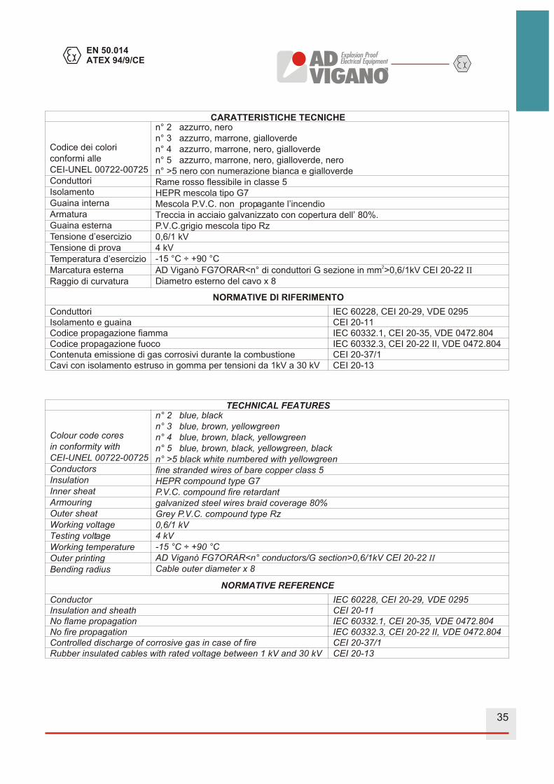
Codice dei colori
conformi alle
CEI-UNEL 00722-00725
Conduttori
Isolamento
Guaina interna
Armatura
Guaina esterna
Tensione d’esercizio
Tensione di prova
Temperatura d’esercizio
Marcatura esterna
Raggio di curvatura
n° 2 azzurro, nero
n° 3 azzurro, marrone, gialloverde
n° 4 azzurro, marrone, nero, gialloverde
n° 5 azzurro, marrone, nero, gialloverde, nero
n° >5 nero con numerazione bianca e gialloverde
Rame rosso flessibile in classe 5
HEPR mescola tipo G7
Mescola P.V.C. non propagante l’incendio
Treccia in acciaio galvanizzato con copertura dell’ 80%.
P.V.C.grigio mescola tipo Rz
0,6/1 kV
4 kV
-15 °C ÷ +90 °C2
AD Viganò FG7ORAR<n° di conduttori G sezione in mm >0,6/1kV CEI 20-22 II
Diametro esterno del cavo x 8
CARATTERISTICHE TECNICHE
NORMATIVE DI RIFERIMENTO
ConduttoriIsolamento e guainaCodice propagazione fiammaCodice propagazione fuocoContenuta emissione di gas corrosivi durante la combustioneCavi con isolamento estruso in gomma per tensioni da 1kV a 30 kV
IEC 60228, CEI 20-29, VDE 0295CEI 20-11IEC 60332.1, CEI 20-35, VDE 0472.804IEC 60332.3, CEI 20-22 II, VDE 0472.804CEI 20-37/1CEI 20-13
35
AD
VIG
AN
O
Expl
osio
nPr
oof
Elec
trica
lEqu
ipm
ent