ad technical report arbrl-tr-02433 an automatic, …
TRANSCRIPT

Ab-AW ftfeo TECHNICAL
LIBRARY
AD
TECHNICAL REPORT ARBRL-TR-02433
AN AUTOMATIC, VELOCITY DEPENDENT DELAY
SYSTEM FOR USE WITHIN AND BEYOND THE
MUZZLE BLAST REGION OF A GUN
Jimmy Q. Schmidt
fate QUALm INBPBCTBD*
October 1982
US ARMY ARMAMENT RESEARCH AND DEVELOPMENT COMMAND BALLISTIC RESEARCH LABORATORY ABERDEEN PROVING GROUND, MARYLAND
Approved for public release; distribution unlimited.
-■
Destroy this report when it is no longer needed, Do not return it to the originator.
Secondary distribution of this report is prohibited
Additional copies of this report may be obtained from the National Technical Information Service, U. S. Department of Commerce, Springfield, Virginia 22161.
The findings in this report are not to be construed as an official Department of the Army position, unless so designated by other authorized documents.
T>ie use of trade y.anes or mjcr.ufaaturera' names in this report- does not aonstitute indorsement of .uny aormeraial product.

UNCLASSIFIED SECURITY CLASSIFICATION OF THIS PAGE (When Data Entered)
REPORT DOCUMENTATION PAGE READ INSTRUCTIONS BEFORE COMPLETING FORM
1. REPORT NUMBER
Technical Report ARBRL-TR-02433
2. GOVT ACCESSION NO. 3. RECIPIENT'S CATALOG NUMBER
4. TITLE fand Sufat/He)
AN AUTOMATIC, VELOCITY DEPENDENT DELAY SYSTEM FOR USE WITHIN AND BEYOND THE MUZZLE BLAST REGION OF A GUN
5. TYPE OF REPORT 4 PERIOD COVERED
6. PERFORMING ORG. REPORT NUMBER
7. AUTHORfs)
JIMMY Q. SCHMIDT
8. CONTRACT OR GRANT NLMBERfs)
9. PERFORMING ORGANIZATION NAME AND ADDRESS
U.S. Army Ballistic Research Laboratory ATTN: DRDAR-BL1 Aberdeen Proving Ground, MD 21QQ5
10. PROGRAM ELEMENT. PROJECT, TASK AREA 4 WORK UNIT NUMBERS
1L162618AH80 II. CONTROLLING OFFICE NAME AND ADDRESS U.S. Army Armament Research § Development Command U.S. Army Ballistic Research Laboratory (DRDAR-BL) Aberdeen Proving Ground, MD 21005
12. REPORT DATE
October 198; 13- NUMBER OF PAGES
22 "iT MONITORING AGENCV NAME 4 HtORESS(ll ditlerent from Controlling Oltlce) IS. SECURITY CLASS, (ot thlt report)
UNCLASSIFIED
ISaT DECLASSIFI CATION/DOWN GRADING SCHEDULE
16. DISTRIBUTION STATEMENT (o( thla Report)
Approved for public release; distribution unlimited
17. DISTRIBUTION STATEMENT (ol the abstract entered In Block 20, U dllterent from Report)
18. SUPPLEMENTARY NOTES
19. KEY WORDS (Continue on reverse aide if neceaaary and identify by block number)
Automatic Delay X-ray Trigger Muzzle Velocity Blast Region
20. ABSTRACT fCorrtfcii* mm rwverwm ait&t tf n«c««M£y and identity by block number) j jfl]^
In ballistic research, it is quite often required to observe the projectile immediately after launch from the gun tube, while it is still in the muzzle blast region of the gun. Flash x-ray photography is an excellent method to record the projectile in this region for evaluation of the structural integrity and the projectile velocity. However, a precise time delay is necessary to assure that the x-ray unit is triggered at the proper time. Normally, the time delay is computed based on the expected velocity, and preset into the x-ray (CONTINUED ON NEXT PAGE1
DO /, FORM AM 73 1473 EDmON OF y MOV 65 IS OBSOLETE UNCLASSIFIED
SECURITY CLASSIFICATtOM OF THIS PAGE (When Data Bntere-d)

UNCLASSIFIED SECURITY CLASSIFICATION OF THIS PAOE(TWi«n Data Bntmnd)
delay circuit. However, round-t9-round variation in the actual velocity can result in the preset delay being inaccurate. This is especially true in research and development programs. A time delay system for use while the projectile is in the muzzle blast region has been developed which will automatically provide a trigger at the correct time regardless of the projectil velocity. Other applications are possible, such as providing the proper time delay to transmit data in an automatic fuze setting system.
UNCLASSIFIED
SECURITY CLASSIFICATION OF THIS PAGEfWien Data Entered)

TABLE OF CONTENTS
Page
LIST OF ILLUSTRATIONS. 5
I. INTRODUCTION 7
A. High-speed Photography 7
B. Flash X-ray Photography , 7
II. THE BASIC CONCEPT OF THE AUTOMATIC DELAY SYSTEM 5
III. THE ELECTRONIC DELAY CIRCUIT u
IV. SYSTEM ACCURACY 14
V. INITIAL TEST RESULTS OF THE AUTOMATIC DELAY SYSTEM 15
VI. SUMMARY 15
REFERENCES ' 18
DISTRIBUTION LIST JJ
LIST OF ILLUSTRATIONS
Figure Page
1. Basic Block Diagram of the Automatic Delay System 9
2. Automatic Delay Triggers in Reference to the X-ray Head Position 10
3. Schematic of the Automatic Delay Circuit 12
4. Time Relationship of the Automatic Delay Circuit Waveforms ... 13
5. X-ray Photograph of a Projectile 35.56 cm From the Muzzle, Muzzle Velocity of the Projectile, 720 m/sec 16
6. X-ray Photograph of a Projectile 35.56 cm Frcm the Muzzle, Muzzle Velocity of the Projectile, 1049 m/sec 16
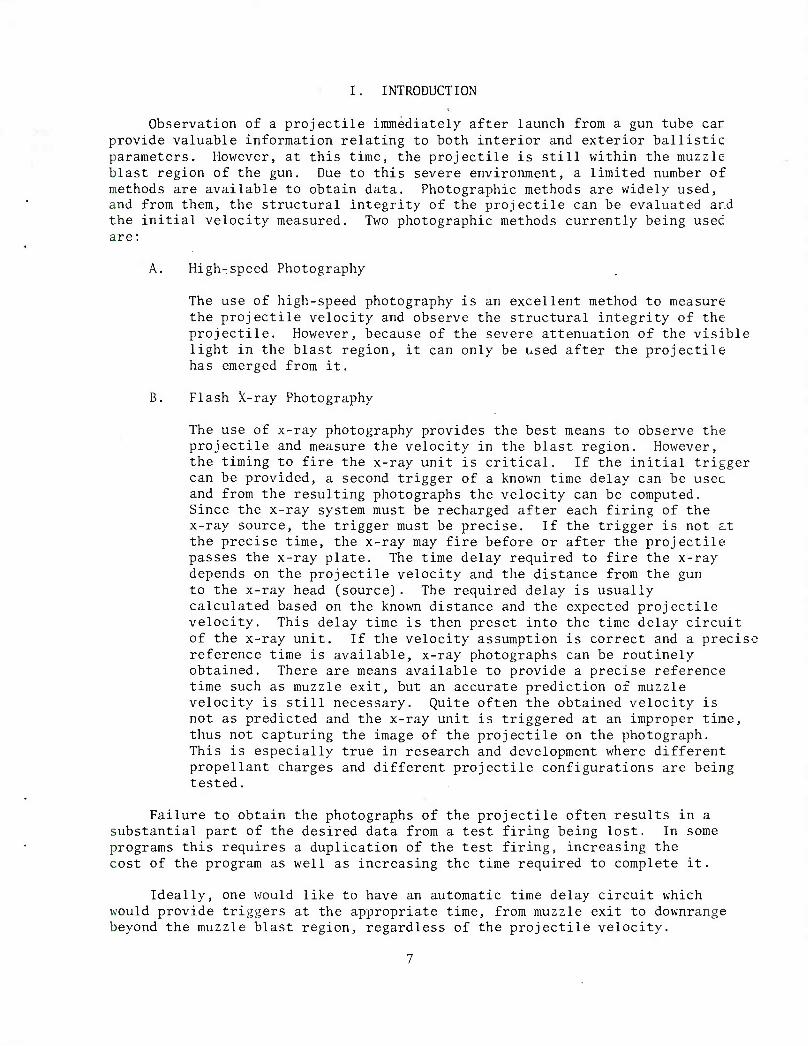
I. INTRODUCTION
Observation of a projectile immediately after launch from a gun tube car provide valuable information relating to both interior and exterior ballistic parameters. However, at this time, the projectile is still within the muzzle blast region of the gun. Due to this severe environment, a limited number of methods are available to obtain data. Photographic methods are widely used, and from them, the structural integrity of the projectile can be evaluated ar.d the initial velocity measured. Two photographic methods currently being used are:
A. High-speed Photography
The use of high-speed photography is an excellent method to measure the projectile velocity and observe the structural integrity of the projectile. However, because of the severe attenuation of the visible light in the blast region, it can only be used after the projectile has emerged from it.
B. Flash X-ray Photography
The use of x-ray photography provides the best means to observe the projectile and measure the velocity in the blast region. However, the timing to fire the x-ray unit is critical. If the initial trigger can be provided, a second trigger of a known time delay can be usec and from the resulting photographs the velocity can be computed. Since the x-ray system must be recharged after each firing of the x-ray source, the trigger must be precise. If the trigger is not at the precise time, the x-ray may fire before or after the projectile passes the x-ray plate. The time delay required to fire the x-ray depends on the projectile velocity and the distance from the gun to the x-ray head (source). The required delay is usually calculated based on the known distance and the expected projectile velocity. This delay time is then preset into the time delay circuit of the x-ray unit. If the velocity assumption is correct and a precise reference time is available, x-ray photographs can be routinely obtained. There are means available to provide a precise reference time such as muzzle exit, but an accurate prediction of muzzle velocity is still necessary. Quite often the obtained velocity is not as predicted and the x-ray unit is triggered at an improper time, thus not capturing the image of the projectile on the photograph. This is especially true in research and development where different propellant charges and different projectile configurations are being tested.
Failure to obtain the photographs of the projectile often results in a substantial part of the desired data from a test firing being lost. In some programs this requires a duplication of the test firing, increasing the cost of the program as well as increasing the time required to complete it.
Ideally, one would like to have an automatic time delay circuit which would provide triggers at the appropriate time, from muzzle exit to downrange beyond the muzzle blast region, regardless of the projectile velocity.

There are several ways by which an automatic x-ray trigger may be obtained. Downrange of the muzzle blast region, for example, one can use an automatic delay circuit in which a digital up-down-counter circuit counts clock pulses "up" during the time it takes a projectile to pass from one light screen or break wire to another. After the projectile passes a second light screen or break wire, the counter counts "down", and when the count reaches zero a pulse is generated to fire the x-ray unit. Assuming no great change in velocity, the projectile travels approximately the same distance during the count "down" as it had during the count "up". If the x-ray heads are positioned accordingly, the x-ray unit will be triggered at the proper time. This system should prove to be a significant improvement over previous methods for obtaining x-ray photographs downrange beyond the muzzle blast. However, since the screens or break wires must be positioned beyond the muzzle blast region, photographs of the projectile while it is still in the blast region are not possible.
It may be possible to measure the time interval of the projectile passing two strain or pressure gages spaced a known distance apart on the gun, near the muzzle, and to use this time in the same way to provide a trigger. This would provide a trigger while the projectile was still in the blast region. These methods of measuring time intervals are not too accurate or reliable.
The automatic time delay system described in this report is designed to provide an x-ray trigger at the precise instant the projectile is passing an x-ray head to ensure a photographic record of the projectile. The primary area of interest is while the projectile is in the muzzle blast region, which typically extends from the muzzle to one to three meters downrange. The system will provide a correct time delay regardless of the projectile velocity. This is possible because a real time measurement of the projectile velocity is made directly at the muzzle of the gun. Therefore, no prior knowledge of the velocity is necessary and there is no need to preset a delay into the x-ray unit. The circuit provides consecutive triggers which coincide in time with the projectile passing multiples of the projectile length. Therefore, multiple x-ray photographs of the projectile can be obtained in the muzzle blast region or downrange beyond this region.
II. THE BASIC CONCEPT OF THE AUTOMATIC DELAY SYSTEM
The basic concept of the system is quite simple. Assuming a constant velocity, a projectile traversing a known distance in a known time will traverse the same distance in the next equivalent increment of time. In this method, the baseline (projectile) length is known, so one need only measure the time required for this baseline to pass a single sensor. The measured time is the correct time delay required to trigger the x-ray if it is positioned one multiple of the baseline from the sensor. Multiples of the measured time also coincide with the projectile passing the respective multiples of the baseline. Although the velocity of the projectile is not constant within the muzzle blast region, the change in velocity is quite small (usually on the
2 Donald F. Merritt and Charles E. Anderson, Jr., "X-ray Trigger Predictor: Automatic Electronic Time Delay Device for Flash X-ray Systems" ARBRL-TB-02284, January 1981. (AD B0S6362L)

order of one half of a percent). After the projectile emerges from the blast region, aerodynamic drag retards the velocity but this change is also quite small. It may be possible to measure these changes in velocity using multiple x-ray heads and precise fiducial marks on the cassettes by measuring the actual position of the projectile relative to the fiducial marks.
Shown in Figure 1 is the basic block diagram of the automatic delay system. The radio frequency (RF) velocimeter,^,3 -^ measuring muzzle velocity, determines the time interval (TI) it takes for the projectile to pass the single sensor which is mounted at the muzzle of the gun. This time interval
RF
Tl PULSE
VELOCIMETEf I
C CLOCK
—1 ^ 5
' \ 1 1 1
I,. PROG. 7C0UNT DCOUh JT ER
MEASURED TIME INTERVAL
DECIMAL COUNTER
PULSE GEN.
X-RAY TRIGGER
OUT
AMP —®
Figure 1. Basic Block Diagram of the Automatic Delay System
measurement is connected to a digital, programmable counter. As soon as the measurement is completed, the programmable counter counts clock pulses derived from a crystal oscillator in the RF velocimeter until the time interval count from the RF velocimeter is reached. At this time the programmable counter outputs a pulse, recycles, and begins the count again. Each time the correct number of clock pulses is counted, a pulse is generated. This results in a pulse train with a repetion rate determined by the time interval measurement. The desired pulse from this pulse train is then selected and amplified to a level sufficient to trigger the x-ray unit. Any number of pulses can be
''Jimmy Q. Schmidt, "A Radio Frequency Oscillator Technique for Measuring Prooeotile Muzzle Velocity," ARBRL-TR-021S8, April 2979. (AD B03S926L)
Rurik K. Loder, Jimmy Q. Schmidt, "Radio Frequency Oscillator Techmque for Monitoring Velocity and Structural Integrity of Projectiles During Their Exit From the Muzzle," ARBRL-MR-0Z100, April 1981. (AD A100725)

selected to trigger multiple x-ray heads. Knowing the baseline length of the projectiles, the x-ray heads are spaced at the desired multiple lengths of the
projectile.
The prototype system was tested using only one x-ray head. Multiples of the baseline length from one to ten were selectable through a switch. Figure 2 shows the time relationship of the x-ray trigger and the x-ray head position. The projectile used was 10.16 cm (4 inches) long. The time interval measure- ment made by the RF velocimeter is complete when the trailing edge of the projectile passes the sensor. Since the collar which holds the sensor to the gun tube is approximately 2.54 cm [1 inch) thick, an x-ray photograph taken at that point in time would provide an image of the projectile which is partially obscured by the collar. Therefore, a reference point is chosen to be one half a projectile length from the sensor and the n=l position to be 10.16 cm (4 inches) from the reference. If an x-ray photograph is taken at this time, the projectile center will coincide with that position and the rear of the projectile will have cleared the collar by 7.62 cm (3 inches). The choice of this reference is arbitrary and can be made whatever is desired.
Shown in Figure 2 is an example where the projectile is to be photographed at n = 4, and the time interval (TI) measured is 110 ysec. The automatic delay provides a trigger 550 ysec after the front of the projectile exits the gun. At this time the center of the projectile is aligned with the x-ray head
X-RAY POSITION HEAD AND PLATE CENTER
PROJECTILE LENGTH 2
SENSOR I
H 1- PROJECTILE LENGTH
H 1- REF. X-l X-2 X-3 X-4 X-5 X-6 X-7 X-8 X-9 X-10
/
I-
TI PULSE
n x 110/xs
X-RAY TRIG
I 1 i i m
-550/is
J I L 1 n = 4
SELECTED
i I I I L
X-RAY TRIGGER DELAY = TIME INTERVAL PULSE DURATION PLUS n TIMES TIME INTERVAL DURATION
n = 4 -TI-(-4(TI)
EX: TI = 110/i.s
DELAY = 110 +4(110)
DELAY = SSO/J-S
EX; PROJECTILE LENGTH - 10.16 cm
REFERENCE AT 5.08 cm PAST MUZZLE FACE
X-RAY HEAD AT 45.72 cm PAST MUZZLE FACE
Figure 2. Automatic Delay Triggers in Reference to the X-ray Head Positions
10

at the x-4 position. Had the projectile been faster, for instance, and a time interval of 100 Msec obtained, the delay would have been-500 psec and the projectile would still have been photographed when the center of the projectile was aligned with the x-ray head. Had the projectile velocity been slower, the correct time delay would also have been obtained.
A fiducial pulse is available from the RF velocimeter, the leading edge of which coincides in time with the front edge of the projectile as it exits the gun. The time delay from this point is (n+1) TI and this time, between muzzle exit and the x-ray trigger is recorded on an external counter to verify the results.
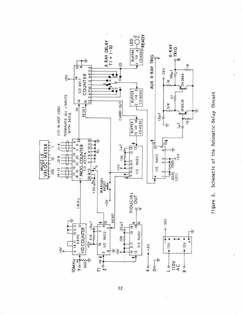
III. THE ELECTRONIC DELAY CIRCUIT
The schematic of the automatic time delay circuit is shown in Figure 3. The associated waveforms for the delay circuit are shown in Figure 4.
4 The programmable counter is initially in the master preset mode (all
binary coded decimal inputs zero] . The time interval output from the RF velocimeter has a resolution of 0.1 ysec. However, only the 1, 10, and 100 ysec decades are coupled into the "J" inputs of the programmable counter. The reason for this is that the programmable counter available had a maximum clock rate of less than 10 MHz. Therefore, only three decades of the time interval count are used. The 10 MHz clock from the RF velocimeter is divided by ten in a decade counter and the output pulses are fed to the programmable counter at a 1 MHz rate.
As the leading edge of the projectile passes the sensor, a positive-going time interval pulse (Tl) is generated in the RF velocimeter and the time interval counter in the RF velocimeter begins to count clock pulses. When the trailing edge of the projectile passes the sensor, the time interval pulse in the RF velocimeter is terminated and the time interval count is completed. The negative-going trailing edge of the time interval pulse (Tl) triggers a one- shot multivibrator. The output of this multivibrator is a positive-going pulse which is coupled to the K^ input of the programmable counter. This causes the programmable counter to switch from the master preset mode to the count mode. The programmable counter then counts the 1 MHz clock pulses until the count is the same as the time interval in microseconds. At this time, it generates a pulse and begins to count again. Therefore, if 110 ysec was fed to the "J" input from the RF velocimeter, every 110 ysec a pulse would be generated. This train of pulses is fed into a CD-4017 decade counter^. The counter counts pulses and outputs consecutive pulses 110 ysec apart on ten separate lines. The ten outputs are fed through a switch and the desired pulse is selected. The selected pulse is fed through a buffer and the positive edge is used to trigger a pulse generator. The pulse generator produces a narrow (5 to 30 ysec) Transistor-Transistor Logic (TTL) level pulse. This pulse is then amplified to a level of 22 volts which is sufficient to trigger the x-ray unit.
When the tenth pulse in the pulse train is counted, the carry-out pulse from the decade counter is coupled through a buffer and used to trigger a one- shot multivibrator. The positive-going output of the multivibrator resets the
"RCA COS/MOS Integrated Circuits,," 1977 Data Book
11
CL
M —
1° .o o
3 o
>1
o
E o
o u
rO E tu
o
QJ s-
CD
12

J
TIME INTERVAL IN
FIDUCIAL OUT
Kb SWITCHES FROM 1 MASTER PRESET TO-r
MODE AND COUNTER
UAHZ n [| 11 n ii n n n n n PROG, COUNTER OUT
rfilViiTmV.!V!!"7"!;T!!"9~ ITTO " 4x TIME INTERVAL i_J_ii u 1 l u u u u u SELECTED
n AUX X-RAY TRIG TTL
X-RAY TRIG GENERATOR TTL
X-RAY TRIG OUT 22V OUT
I ' CARRY OUT
P ' RESET TO COUNTER
1_ RESET TO Kb INPUT MULT.
TIME INTERVAL PULSE (MAX - NOT RESET BY SIGNAL) « 900/isec FIDUCIAL OUT - TTL « 630/i.sec AUX X-RAY TRIG - TTL, 30/isec (.01), 5/i.sec (.0022) X-RAY TRIG, 22.2 V OPEN CIRCUIT, 22V INTO 51 ft Tr a 50 ns X-RAY TRIGGERS DELAY, SWITCHABLE 1-10 TIMES TIME INTERVAL PULSE
DURATION (MAX. Tl = gOO^sec) TIME DELAY IN REFERENCE TO TRAILING EDGE OF TIME INTERVAL PULSE
DELAY ACCURACY, 1-10 TIMES Tl PULSE (IN/isec) PLUS MAX OF 1 ADDITIONAL/xsec (ALL POSITIONS)
IF GREEN LED DOES NOT LIGHT AT POWER "ON", PRESS RESET ON AUTO X-RAY TO RESET COUNTER TO ZERO. IF LED IS OFF, THE FIRST COUNT WILL BE WRONG BUT WILL AUTOMATICALLY RESET ITSELF FOR SUCCEEDING PULSES
NOTE: HP X-RAY TRIG DELAY, MINIMUM DELAY 1 .O^sec
Figure 4. Time Relationship of the Automatic Delay Circuit Waveforms
13

decade counter to zero. The negative-going pulse of the multivibrator resets the first one-shot multivibrator which, in turn, resets the programmable counter to the master preset mode for the next firing. An additional one-shot multivibrator is triggered on the positive-going leading edge of the time interval pulse to supply a timing fiducial mark. This simply replaces the fiducial pulse normally available from the velocimeter since the circuit card holding the automatic delay circuit replaced the original fiducial and x-ray trigger card. An indicator light and a manual reset is included to ensure that the decade counter is properly reset after initial power is applied.
Should it be desired to use multiple x-ray heads it is a simple matter to connect additional pulse generators and amplifiers directly to the ten output lines of the decade counter.
Additional decades can be added to the decade counter circuit if it is desired to take x-ray photographs at a greater distance than ten times the projectile length. The same effect can be achieved by increasing the division ratio of the divide-by-ten counter.
IV. SYSTEM ACCURACY
The accuracy of the position of the projectile (assuming a constant velocity) in reference to the x-ray head at the time of the trigger is deter- mined by:
A. The accuracy of the time interval measurement by the velocimeter,
B. The selected baseline multiple, and
C. A maximum of plus 1 ysec due to the time of the event in relation- ship to the clock pulse.
The position error A can be written as P
Ap = (n(ATI) + ^ M,
where n is the multiple of the baseline selected, A is the accuracy of the time interval measurement, Tl is the time interval m ysec, and HA is the projectile baseline length.
As an example, the maximum position error for a 10.16 cm (4 inch) projec- tile to be photographed at n = 10 with a projectile velocity of approximately 1000 m/sec and a time interval accuracy of 1% would be:
Ap = CnCA^] + ^ ) A
Ap = (10(.01) + lop ^ 10-16
A = 1.12 cm (0.44 inches) P
14
This position error is sufficiently small to ensure capturing the projectile image on the x-ray film. The error can be reduced further by the use of a programmable counter operating at a 10 MHz rate and using the full resolution of the time interval measurement of the RF velocimeter.
V. INITIAL TEST RESULTS OF THE AUTOMATIC DELAY SYSTEM
The automatic time delay system was first tested on a 40 mm gun from 13 May 1981 to 11 June 1981. Twenty-four rounds were fired with the projectile muzzle velocities varying from approximately 340 m/sec to 1049 m/sec. X-ray photographs were taken of the projectiles at one, three, and five times the projectile baseline length of 10.16 cm (4 inches). The time between the muzzle exit and the x-ray trigger was recorded on an external counter. A threaded rod was positioned at the selected multiple of the baseline to check the projectile position. The x-ray unit was triggered at the proper time in each case. Figures 5 and 6 are examples of two projectiles x-ray photographed at the (x-3) position (35.56 cm from the muzzle). The respective muzzle velocities, as measured by the RF velocimeter, are 720 m/sec and 1049 m/sec. The recorded time delay based on the time interval measurement was also correct to within 1 ysec.
VI. SUMMARY
The automatic delay system has been proven to be an excellent method to provide an accurate and reliable trigger for obtaining x-ray photographs of projectiles in the muzzle blast region of a gun. The primary advantages of this system over previous systems are:
A. The system will automatically provide triggers during which time the projectile is in the muzzle blast region as well as beyond the blast region.
B. The projectile length is used as the baseline distance for the time interval measurement. The projectile length, being much shorter than a typical spacing required for light screens or break wires provides smaller increments of projectile travel which may be automatically timed.
C. The velocity used to compute the delay is the actual real time measurement at the muzzle.
D. There is no realignment necessary between rounds as may be the case when using screens or break wires.
E. There is no restriction in the azimuth or elevation position of the gun which would be advantageous in other applications such as automatic fuze setting.
In addition to its primary purpose of reliably obtaining the desired x-ray photographs, this system has the potential to provide a measurement of the change in projectile velocity from the muzzle to the time the projectile emerges from the muzzle blast region.
15

Figure 5. X-ray Photograph of a Projectile 35.56 cm From the Muzzle, Muzzle Velocity of the Projectile, 720 m/sec
Figure 6. X-ray Photograph of a Projectile 35.56 cm From the Muzzle, Muzzle Velocity of the Projectile, 1049 m/sec
16

■
It should also be applicable to an automatic fuze setting system where the data to set the fuze must be transmitted to the projectile at a precise instant shortly after muzzle exit.
17

REFERENCES
1. Donald F. Merritt and Charles E. Anderson, Jr., "X-Ray Trigger Predictor; Automatic Electronic Time Delay Device for Flash X-ray Systems," ARBRL-TR-02284, January 1981. (AD B056362L)
2. Jimmy Q. Schmidt, "A Radio Frequency Oscillator Technique for Measuring Projectile Muzzle Velocity," ARBRL-TR-02158, April 1979. (AD B038926L)
3. Rurik K. Loder, Jimmy Q. Schmidt, "Radio Frequency Oscillator Technique for Monitoring Velocity and Structural Integrity of Projectiles During Their Exit From the Muzzle," ARBRL-MR-03100, April 1981. (AD A100725)
4. "RCA COS/MOS Integrated Circuits," 1977 Data Book.
18
DISTRIBUTION LIST
No. of Copies Organization
No. of Copies Organization
12 Administrator Defense Technical Info Center ATTN: DTIC-DDA Cameron Station Alexandria, VA 22314
2 Director Defense Advanced Research
Projects Agency 1400 Wilson Boulevard Arlington, VA 22209
1 Director Defense Nuclear Agency Washington, DC 20305
1 Commander US Army BMD Advanced Technology Center
ATTN: BMDATC-M P.O. Box 1500 Huntsville, AL 35804
1 Commander US Army Materiel Development
and Readiness Command ATTN: DRCDMD-ST 5001 Eisenhower Avenue Alexandria, VA 22333
5 Commander USA ARRADCOM ATTN: DRDAR-TSS (2 cys]
DRDAR-TD DRDAR-TDA DRDAR-TDS
Dover, NJ 07801
10 Commander USA ARRADCOM ATTN: DRDAR-LCA
DRDAR-LCW DRDAR-LCE DRDAR-LCM DRDAR-LCN DRDAR-LCU DRDAR-LC DRDAR-LCS-D, Mr. K. Rubin
Maj. J. Houle DRDAR-TDC
Dover, NJ 07801
6 Commander USA ARRADCOM ATTN: DRDAR-SC
DRDAR-SA DRDAR-SCM DRDAR-SCS DRDAR-SCA DRDAR-SCF
Dover, NJ 07801
2 Commander USA ARRADCOM ATTN: DRDAR-SE Dover, NJ 07801
2 Commander USA ARRADCOM Product Assurance Directorate ATTN: DRDAR-QA Dover, NJ 07801
1 Commander USA ARRADCOM ATTN: DRDAR-FU Dover, NJ 07801
1 Commander USA ARRADCOM ATTN: DRDAR-DP Dover, NJ 07801
1 Director Benet Weapons Laboratory USA ARRADCOM ATTN: DRDAR-LCB-TL Watervliet, NY 12189
1 Commander US Army Rock Island Arsenal ATTN: DRDAR-TSE-SW, R. Radkiewicz Rock Island, IL 61299
1 Commander US Army Armament Materiel
Readiness Command ATTN: DRSAR-LEP-L, Tech Lib Rock Island, IL 61299
19

DISTRIBUTION LIST
No. of Copies
1
Organization
Commander US Army Aviation Research
and Development Command ATTN: DRDAV-E 4300 Goodfellow Blvd. St. Louis, MO 63120
Director US Army Air Mobility Research
and Development Laboratory Ames Research Center Moffett Field, CA 94035
2 Director US Army Research and Technology Laboratories (AVRADCOM)
Ames Research Center Moffett Field, CA 94035
1 Commander US Army Communications Rsch
and Development Command ATTN: DRDCO-PPA-SA Fort Monmouth, NJ 07703
1 Commander US Army Electronics Research
and Development Command Technical Support Activity ATTN: DELSD-L Fort Monmouth, NJ 07703
3 Commander US Army Harry Diamond Labs ATTN: H. Davis
H. Curchack DELHD-S-OE-ES, Ben Banner
2800 Powder Mill Road Adelphi, MD 20783
1 Commander US Army Missile Command ATTN: DRSMI-R Redstone Arsenal, AL 35898
1 Commander US Army Missile Command ATTN: DRSMI-YDL Redstone Arsenal, AL 35898
■No. of Copies Organization
Commander US Army Missile Command ATTN: DRSMI-RBL Redstone Arsenal, AL 35898
Commander US Army Tank Automotive Research
and Development Command ATTN: DRDTA-UL
Technical Director Warren, MI 48090
Commander US Army Jefferson Proving Ground ATTN: STEJP-TD-0, Arnold Tilley
STEJP-TD-E, Joseph Tooney Madison, IN 47250
Commander US Army Yuma Proving Ground ATTN: STEYP-MTW, Robert Torp,
Graham Stullenbarger Yuma, AZ 85364
President US Army Armor and Engineer Board ATTN: ATZK-RE-CV
ATZK-RE-IN, Mr. Larry Smith Fort Knox, KY 40121
Project Manager Division Air Defense Gun ATTN: DRCPM-ADG Dover, NJ 07801
Project Manager Cannon Artillery Weapons System ATTN: DRCPM-CAWS Dover, NJ 07801
Project Manager Nuclear Munitions ATTN: DRCPM-NUC Dover, NJ 07801
Project Manager Tank Main Armament Systems ATTN: DRCPM-TMA Dover, NJ 07801
20

DISTRIBUTION LIST
No. of Copies Organization
No. of Copies Organization
1 Product Manager for 30nim Ammo. ATTN: DRCPM-AAH-30mra Dover, NJ 07801
2 Product Manager MI10E2 Weapon System, DARCOM ATTN: DRCPM-M110E2 Rock Island, IL 61299
4 Director USA Mechanics and
Materials Research Center ATTN: Director (3 cy)
DRXMR-ATL (1 cy) Watertown, MA 02172
3 Commander US Army Research Office P.O. Box 12211 ATTN: Technical Director
Engineering Division Metallurgy § Materials Division
Research Triangle Park NC 27709
1 Director US Army TRADOC Systems
Analysis Activity ATTN: ATAA-SL (Tech Lib) White Sands Missile Range, NM
1 Commander Naval Air Systems Command Washington, DC 20360
1 Commander Naval Sea Systems Command Washington, DC 20362
1 Commander Naval Sea Systems Command ATTN: SEA-03513, L. Pasiuk Washington, DC 20362
1 Commander Naval Air Development Center Johnsville
Warminster, PA 18974
88002
1 Commander Naval Missile Center Point Mugu, CA 93041
2 Commander David W, Taylor Naval Ship Research
and Development Center Bethesda, MD 20084
2 Commander Naval Surface Weapons Center Dahlgren, VA 22448
4 Commander Naval Surface Weapons Center ATTN: Code G-33, T.N. Tschirn
Code N-43, J.J. Yagla L. Anderson G. Soo Hoo
Dahlgren, VA 22448
3 Commander Naval Surface Weapons Center ATTN: Code E-31, R.C. Reed
M.T. Walchak Code V-14, W.M. Hinckley
Silver Spring, MD 20910
2 Commander Naval Surface Weapons Center Silver Spring, MD 20910
2 Commander Naval Weapons Center China Lake, CA 93555
3 Commander Naval Weapons Center ATTN: J. O'Malley
D. Potts R.G, Sewell
China Lake, CA 93555
1 Commander Naval Research Laboratory Washington, DC 20375
21

DISTRIBUTION LIST
No. of Copies Organization
1 Superintendent Naval Postgraduate School ATTN: Dir of Lib Monterey, CA 93940
1 Commander Naval Ordnance Station Indian Head, MD 20640
2 Commander Naval Ordnance Station ATTN: Code 5034, Ch, Irish Jr.^
T. C. Smith Indian Head, MD 20640
2 AFATL Eglin AFB, FL 32542
3 AFATL (DLJM, W. Dittrich; DLD, D. Davis; DLDL)
Eglin AFB, FL 32542
2 AFWL/SUL Kirtland AFB, NM 87115
I Director Lawrence Livermore Lab P, 0. Box 808 Livermore, CA 94550
1 Director Los Alamos Scientific Lab P.O. Box 1663 Los Alamos, NM 87544
No. of Copies Organization
2 ARES Inc. ATTN; Duane Summers
Phil Conners Port Clinton, OH 43452
1 General Electric Company ATTN: Armament Systems Dept.
David A. Graham Lakeside Avenue Burlington, VT 05402
Aberdeen Proving Ground
Dir, USAMSAA ATTN: DRXSY-D
DRXSY-G, E. Christman DRXSY-OSD, H. Burke DRXSY-G, R.C. Conroy DRXSY-LM, J.C.C. Fine DRXSY-MP, H. Cohen
Dir, USAHEL ATTN: A.H. Eckles, III
Cdr, USATECOM ATTN: DRSTE-TO-F
Dir, USACSL, Bldg. E3516, EA ATTN: DRDAR-CLB-PA
DRDAR-CL DRDAR-CLB DRDAR-CLD DRDAR-CLY DRDAR-CLN
Cdr, USAAPG ATTN: STEAP-MT-G, James Fasig
Kenneth Balliet
2 Director National Aeronautics and
Space Administration Langley Research Center Langley Station Hampton, VA 23365
1 Aircraft Armaments Inc. ATTN: John Hebert York Road 7 Industry Lane Cockeysville, MD 21030
22

USER EVALUATION OF REPORT
Please take a few minutes to answer the questions below; tear out this sheet, fold as indicated, staple or tape closed, and place in the mail. Your comments will provide us with information for improving future reports.
1. BRL Report Number
2. Does this report satisfy a need? (Comment on purpose, related project, or other area of interest for which report will be used.)
3. How, specifically, is the report being used? (Information source, design data or procedure, management procedure, source of ideas, etc.)
4. Has the information in this report led to any quantitative savings as far as man-hours/contract dollars saved, operating costs avoided, efficiencies achieved, etc.? If so, please elaborate.
5. General Comments (Indicate what you think should be changed to make this report and future reports of this type more responsive to your needs, more usable, improve readability, etc.)
6. If you would like to be contacted by the personnel who prepared this report to raise specific questions or discuss the topic, please fill in the following information.
Name:
Telephone Number:
Organization Address: