adafruit si4713 fm radio transmitter with rds/rdbs support · overview yaaar! become your very own...
TRANSCRIPT

Adafruit Si4713 FM Radio Transmitter with RDS/RDBS SupportCreated by lady ada
Last updated on 2014-07-09 11:00:12 AM EDT

237777899
1011141414151820202021212123232323
Guide Contents
Guide ContentsOverviewPinoutsAudio InputsPower PinsInterface Pins
Extra GPIO PinsAssembly
Prepare the header strip:Add the breakout board:And Solder!
Test & UsageArduino WiringDownload Adafruit_Si4713Load DemoUsing the RPS Scanning functionLibrary Reference
Radio Transmitter controlRPS (Radio Power Sensing)RDS/RBDS (Radio Data Broadcast)GPIO ControlAdvanced!
DownloadsDatasheetsLayout PrintSchematic
© Adafruit Industries https://learn.adafruit.com/adafruit-si4713-fm-radio-transmitter-with-rds-rdbs-support
Page 2 of 24

Overview
Yaaar! Become your very own pirate radio station with this FM radio transmitter. Thisbreakout board, based on the best-of-class Si4713, is an all-in-one stereo audio FMtransmitter that can also transmit RDS/RBDS data!
© Adafruit Industries https://learn.adafruit.com/adafruit-si4713-fm-radio-transmitter-with-rds-rdbs-support
Page 3 of 24
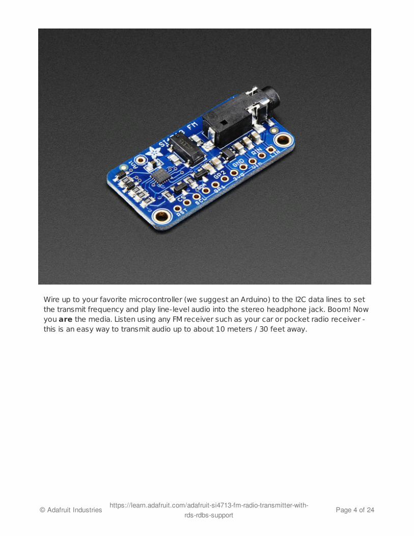
Wire up to your favorite microcontroller (we suggest an Arduino) to the I2C data lines to setthe transmit frequency and play line-level audio into the stereo headphone jack. Boom! Nowyou are the media. Listen using any FM receiver such as your car or pocket radio receiver -this is an easy way to transmit audio up to about 10 meters / 30 feet away.
© Adafruit Industries https://learn.adafruit.com/adafruit-si4713-fm-radio-transmitter-with-rds-rdbs-support
Page 4 of 24

This transmitter even has RDS/RBDS support - that's text/data transmissions that manymodern FM receivers support. (It's how some car radios can display the FM station andcurrent song playing). You can transmit just about any text you want, set the station identifieras well as the 'freeform' buffer.
© Adafruit Industries https://learn.adafruit.com/adafruit-si4713-fm-radio-transmitter-with-rds-rdbs-support
Page 5 of 24

Best of all, you'll be up and running in minutes with our awesome Arduino library, examplecode and tutorial!
© Adafruit Industries https://learn.adafruit.com/adafruit-si4713-fm-radio-transmitter-with-rds-rdbs-support
Page 6 of 24

PinoutsThere's a couple pins on this here breakout, lets cover them all in groupings by 'type'
Audio InputsLIN - this is the line level LEFT input. Its connected to the headphone jack as well butin case you want to wire directly without a chunky cable, pipe line level (~0.7 Vpp)audio into here. There's an AC blocking capacitor on board so it can be DC biasedRIN - same as LIN but the RIGHT input.
Power PinsVin - this is the power input pin. You can power the chip from 3-5VDC. Ideally youshould use the same voltage you use for logic levels. For an Arduino, that's usually 5VGND - this is power and logic ground, connect to your microcontroller's ground pin3Vo - this is the output from the onboard regulator, 3.3V nominal. You can use this ifyou need up to 100mA of 3V regulated voltage
Interface PinsThe FM transmitter chip requires a microcontroller for setting it up unlike pure-analogsolutions that have a tuning potentiometer. The trade off is some code is needed, but theoutput is digitally tuned so its much more precise.Our codebase uses I2C to communicate. The chip supports SPI as well but it was annoying
© Adafruit Industries https://learn.adafruit.com/adafruit-si4713-fm-radio-transmitter-with-rds-rdbs-support
Page 7 of 24
enough to support just I2C so we don't have code examples for SPI!
All the interface input pins are 5V friendly, and can be used with 3-5V logic
RST - This is the Reset pin. You must have this pin toggle before starting tocommunicate with the chip. When at logic 0, the chip is in reset.CS - This is the Chip select pin, used in SPI mode. It also determines the I2C address.When pulled high (it is by default) the I2C address is 0x63. If this pin is shorted toground, the I2C address is 0x11SCL - this is the I2C clock pin, connect to SCL on your microcontroller.SDA - this is the I2C data pin, connect to SDA on your microcontroller.
Extra GPIO PinsThere's also two "GPIO" pins, you can use these to blink LEDs. The initial state of these pinsets up the chip for Analog Mode so don't short them to ground or VCC during reset. Theyare 3V output only!
GP1 - this is GPIO #1GP2 - this is GPIO #2
GPIO #3 is used for the 32Khz clock generator onboard.
© Adafruit Industries https://learn.adafruit.com/adafruit-si4713-fm-radio-transmitter-with-rds-rdbs-support
Page 8 of 24

Assembly
Prepare the header strip:Cut the strip to length if necessary. It will beeasier to solder if you insert it into abreadboard - long pins down
© Adafruit Industries https://learn.adafruit.com/adafruit-si4713-fm-radio-transmitter-with-rds-rdbs-support
Page 9 of 24

Add the breakout board:Place the breakout board over the pins so thatthe short pins poke through the breakout pads
© Adafruit Industries https://learn.adafruit.com/adafruit-si4713-fm-radio-transmitter-with-rds-rdbs-support
Page 10 of 24

And Solder!Be sure to solder all pins for reliable electricalcontact.
(For tips on soldering, be sure to check outour Guide to ExcellentSoldering (http://adafru.it/aTk)).
© Adafruit Industries https://learn.adafruit.com/adafruit-si4713-fm-radio-transmitter-with-rds-rdbs-support
Page 11 of 24

You're done! Check your solder joints visuallyand continue onto the antenna
An antenna is required! We provide a 1meterlong wire but you can also use a shorter orlonger piece as desired.Strip a few mm from the end
Hook the exposed wire end into the ANT hole
© Adafruit Industries https://learn.adafruit.com/adafruit-si4713-fm-radio-transmitter-with-rds-rdbs-support
Page 12 of 24

Solder it in!
Done!
© Adafruit Industries https://learn.adafruit.com/adafruit-si4713-fm-radio-transmitter-with-rds-rdbs-support
Page 13 of 24

Test & UsageArduino Wiring
You can easily wire this breakout to any microcontroller, we'll be using an Arduino. Foranother kind of microcontroller, just make sure it has I2C, then port the code - once the lowlevel i2c functions are adapted the rest should 'fall into place'
(http://adafru.it/dBn)
(http://adafru.it/dBo)
Connect Vin to the power supply, 3-5V is fine. Use the same voltage that themicrocontroller logic is based off of. For most Arduinos, that is 5VConnect GND to common power/data groundConnect the SCL pin to the I2C clock SCL pin on your Arduino. On an UNO & '328based Arduino, this is also known as A5, on a Mega it is also known as digital 21 andon a Leonardo/Micro, digital 3Connect the SDA pin to the I2C data SDA pin on your Arduino. On an UNO & '328based Arduino, this is also known as A4, on a Mega it is also known as digital 20 andon a Leonardo/Micro, digital 2Connect the RST pin to digital 12 - you can change this later but we want to match thetutorial for now
The Si4713 has a default I2C address of 0x63 - you can change it to 0x11 by connecting CSto ground but don't do that yet! Get the demo working first before making changes
Download Adafruit_Si4713To begin reading sensor data, you will need to download Adafruit_Si4713 Library from ourgithub repository (http://adafru.it/dBp). You can do that by visiting the github repo andmanually downloading or, easier, just click this button to download the zip
Download Adafruit_Si4713Arduino Library
http://adafru.it/dBq
Rename the uncompressed folder Adafruit_Si4713 and check that the Adafruit_Si4713folder contains Adafruit_Si4713.cpp and Adafruit_Si4713.h
Place the Adafruit_Si4713 library folder your arduinosketchfolder/libraries/ folder. You may need to create the libraries subfolder if its your first library. Restart the IDE.
© Adafruit Industries https://learn.adafruit.com/adafruit-si4713-fm-radio-transmitter-with-rds-rdbs-support
Page 14 of 24

We also have a great tutorial on Arduino library installation at:http://learn.adafruit.com/adafruit-all-about-arduino-libraries-install-use (http://adafru.it/aYM)
Load DemoOpen up File->Examples->Adafruit_Si4713->HTU21DFtest and upload to yourArduino wired up to the sensor
You may want to update the FM station transmission. By default the library transmits on102.3MHz FM, but that might be 'taken' in your area.
Find this line
#define FMSTATION 10230 // 10230 == 102.30 MHz
And change it to an unused frequency. This number is in 10KHz so for example 88.1MHz iswritten as 8810
Upload it to your Arduino and open up the Serial console at 9600 baud
© Adafruit Industries https://learn.adafruit.com/adafruit-si4713-fm-radio-transmitter-with-rds-rdbs-support
Page 15 of 24

© Adafruit Industries https://learn.adafruit.com/adafruit-si4713-fm-radio-transmitter-with-rds-rdbs-support
Page 16 of 24

As long as you get to the RDS On! message that means everything works, pipe someaudio into the 3.5mm jack and make sure you see the InLevel audio volume range from 0to about -10 (dB)
The fastest way to test the RDS message sending is using an RTL-SDR (that's how wedebugged the breakout!) (http://adafru.it/dBr) or a phone/radio that can do RDS decoding
© Adafruit Industries https://learn.adafruit.com/adafruit-si4713-fm-radio-transmitter-with-rds-rdbs-support
Page 17 of 24

Using the RPS Scanning function
The Si4713 has the ability 'scan' the FM band and measure the input power. You can use theRPS functionality to locate a good unused station. Find this section in the adaradio demo anduncomment the for loop:
Reupload and look at the serial console:
// Uncomment below to scan power of entire range from 87.5 to 108.0 MHz
/*
for (uint16_t f = 8750; f<10800; f+=10) {
radio.readTuneMeasure(f);
Serial.print("Measuring "); Serial.print(f); Serial.print("...");
radio.readTuneStatus();
Serial.println(radio.currNoiseLevel);
}
*/
© Adafruit Industries https://learn.adafruit.com/adafruit-si4713-fm-radio-transmitter-with-rds-rdbs-support
Page 18 of 24

The larger the number the higher the transmission power. For example, 96.3MHz is a highernumber than the others (FYI, its Univision 96.3 FM (http://adafru.it/dBs)!) whereas 95.1 MHz isnice as low, that's not used for any transmission. Try to find a number that's also not
© Adafruit Industries https://learn.adafruit.com/adafruit-si4713-fm-radio-transmitter-with-rds-rdbs-support
Page 19 of 24

surrounded by high numbers, since it can get 'drowned out' by the nearby frequencies.
Library Reference
Radio Transmitter controlStart out by initializing the Si4713 chipset with
begin()
This will return true if the radio initialized, and false if the radio was not found. Check yourwiring if its not 'showing up'
Then you can turn on the radio transmitter with
setTXpower(txpwr)
the txpwr number is the dB�V transmission power. You can set this to 88-115dB�V or 0 (foroff)
Of course, you'll want to tune the transmitter! Do that with
tuneFM(freq)
That will set the output frequency, in 10's of KHz. So if you want to tune to 101.9 thefrequency value is 10190
You can check in on the radio with
readTuneStatus()
Whcih will set the currFreq currdBuV adnd currAntCap variables in the radio object. Thefirst two are the frequency and power output, the third variable is the tuning antennacapacitor it set for the best output. This number will vary with antenna size and frequency.
RPS (Radio Power Sensing)This function is used with two procedures.
readTuneMeasure(freq)
begins the measurement, freq is in units of 10KHz so 88.1MHz is written in as 8810Then you have to call
© Adafruit Industries https://learn.adafruit.com/adafruit-si4713-fm-radio-transmitter-with-rds-rdbs-support
Page 20 of 24

readTuneStatus()
which will wait until the chip has measured the data and stick it into the currNoiseLevelvariable
RDS/RBDS (Radio Data Broadcast)The Si4713 has great support for sending RDS data and we made it real easy too. Initializethe subsystem with
beginRDS()
Then you can set the "station name" with
setRDSstation("AdaRadio")
The radio station name is up to 8 charactersYou can also send the main buffer which usually contains the song name/artist.
setRDSbuffer( "Adafruit g0th Radio!")
You can send up to 32 characters, but you can continuously send new data, just wait a fewseconds before each data rewrite so the listener's radio has received all the data
GPIO ControlThere's two GPIO pins you can use to blink LEDs. They are GPIO1 and GPIO2 - GPIO3 isused for the oscillator. To set them to be outputs call
setGPIOctrl(bitmask)
where the bitmask has a 1 bit for each of the two pins. For example to set GPIO2 to be anoutput use setGPIOctrl((1<<2)) to set both outputs, use setGPIOctrl((1<<2) || (1<<1))
Then you can set the output with
setGPIO(bitmask)
same idea with the bitmask, to turn both on, use setGPIOctrl((1<<2) || (1<<1)). To turnGPIO2 on and GPIO1 off, setGPIOctrl(1<<2)
Advanced!
We, by default, use the built-in AGC (auto-gain control) system so the audio level is maxedout. This may be annoying to you if have a good quality line level and the volume is
© Adafruit Industries https://learn.adafruit.com/adafruit-si4713-fm-radio-transmitter-with-rds-rdbs-support
Page 21 of 24

fluctuating (it should be quiet, but isnt)
in the Adafruit_Si4713.cpp file find these lines
//setProperty(SI4713_PROP_TX_ACOMP_ENABLE, 0x02); // turn onlimiter, but no dynamic rangingsetProperty(SI4713_PROP_TX_ACOMP_ENABLE, 0x0); // turn on limiterand AGC
and uncomment the first one, and comment the second. This will turn off the AGC
© Adafruit Industries https://learn.adafruit.com/adafruit-si4713-fm-radio-transmitter-with-rds-rdbs-support
Page 22 of 24

DownloadsDatasheets
Si4713 Datasheet (http://adafru.it/dBc)(this does not include any software interfacingdetails)Si47xx Programming guide (http://adafru.it/dBd) - contains all the nitty-gritty details oncommand data packets etc.
Layout PrintDimensions in Inches
Schematic
© Adafruit Industries https://learn.adafruit.com/adafruit-si4713-fm-radio-transmitter-with-rds-rdbs-support
Page 23 of 24

© Adafruit Industries Last Updated: 2014-07-09 11:00:15 AM EDT Page 24 of 24