adam john spitz - architect
DESCRIPTION
2010 PortfolioTRANSCRIPT

A D A M J O H N S P I T Z
P O R T FO L I O | 2010

adamjspitz.com
S E C T I O N O N E
ADA M J O H N SPI T Z
Work and Education background, contact information, and, project experience, and summary of quali-fications.
S E C T I O N T W O
PR O FE SSI O NAL WO R K
Selected projects completed, and in progress during professional career with HOK Atlanta, 2007-present
S E C T I O N T H R E E
T H E UN I V ER SI T Y O F T ENN E SSEE
Selected projects submitted at the University of Tennessee, 2002-2007
A D A M J O H N S P I T ZA R C H I T E C T

adamjspitz.com
A D A M J O H N S P I T Z
RESUME, SUMMARY OF QUALIFICATIONS
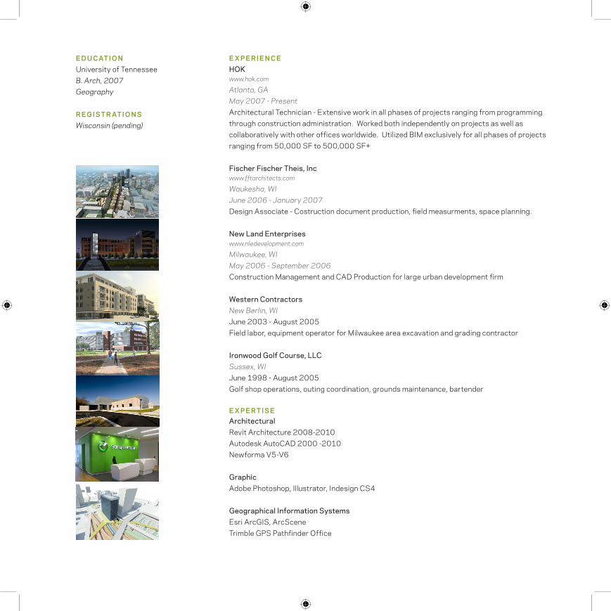
EXPERIENCEHOKwww.hok.com
Atlanta, GAMay 2007 - PresentArchitectural Technician - Extensive work in all phases of projects ranging from programming through construction administration. Worked both independently on projects as well as collaboratively with other offices worldwide. Utilized BIM exclusively for all phases of projects ranging from 50,000 SF to 500,000 SF+
Fischer Fischer Theis, Incwww.fftarchitects.com
Waukesha, WIJune 2006 - January 2007Design Associate - Costruction document production, field measurments, space planning.
New Land Enterpriseswww.nledevelopment.com
Milwaukee, WIMay 2006 - September 2006Construction Management and CAD Production for large urban development firm
Western ContractorsNew Berlin, WIJune 2003 - August 2005Field labor, equipment operator for Milwaukee area excavation and grading contractor
Ironwood Golf Course, LLCSussex, WIJune 1998 - August 2005 Golf shop operations, outing coordination, grounds maintenance, bartender
ArchitecturalRevit Architecture 2008-2010Autodesk AutoCAD 2000 -2010Newforma V5-V6
GraphicAdobe Photoshop, Illustrator, Indesign CS4
Geographical Information SystemsEsri ArcGIS, ArcSceneTrimble GPS Pathfinder Office
EXPERTISE
EDUCATIONUniversity of TennesseeB. Arch, 2007 Geography
REGISTRATIONSWisconsin (pending)
adamjspitz.com
C O N TA C T
Adam John Spitz
3400 Stratford Rd.
Apt. 4104
Atlanta, GA 30326
(414) 719 - 6716 (M)
(678) 954 - 8891 (O)
adam.john,[email protected]
http://www.adamjspitz.com

B.I.M. - BUILDING INFORMATION MODELING
• Efficient workflow, understanding of building information modeling
• Exclusive use of B.I.M. systems for over 75% of work completed in professional career, resulting in a deep understanding of how to construct accurate and efficient building models that benefit staff, contractor, and client.
EXPERIENCE - CONCEPT THROUGH CONSTRUCTION
• Utilization of B.I.M. in all phases under design-bid-build, design-build, and CM at risk.
• High level of contact and coordination with designers and project engineers, as well as experience working with outside offices and international clients and consultants.
• Pre-professional experience translates to fundamental knowledge of of scheduling and effective communcation with contractors.
BUILDING SYSTEMS KNOWLEDGE
• Strong understanding of building systems and proper detailing for performance and cost value.
• Experience detailing a variety of systems including curtainwall, precast, rainscreen, composite metal panel, and masonry, with minimal supervision. Experience in specification writing and modification for building envelope systems.
adamjspitz.com
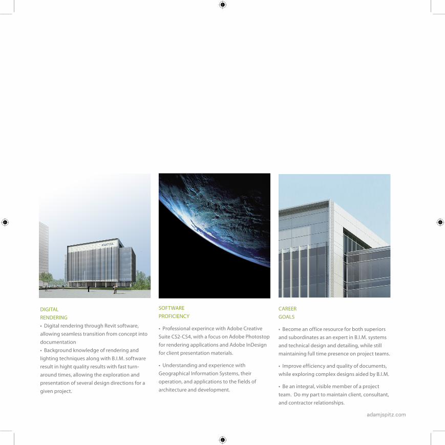
DIGITAL RENDERING • Digital rendering through Revit software, allowing seamless transition from concept into documentation• Background knowledge of rendering and lighting techniques along with B.I.M. software result in hight quality results with fast turn-around times, allowing the exploration and presentation of several design directions for a given project.
SOFTWARE PROFICIENCY
• Professional experince with Adobe Creative Suite CS2-CS4, with a focus on Adobe Photostop for rendering applications and Adobe InDesign for client presentation materials.
• Understanding and experience with Geographical Information Systems, their operation, and applications to the fields of architecture and development.
CAREER GOALS
• Become an office resource for both superiors and subordinates as an expert in B.I.M. systems and technical design and detailing, while still maintaining full time presence on project teams.
• Improve efficiency and quality of documents, while exploring complex designs aided by B.I.M.
• Be an integral, visible member of a project team. Do my part to maintain client, consultant, and contractor relationships.

07-10S E L E C T E D P R O J E C T S
• Southwestern Energy HQ Building
• The Green Line
• Al Maha Community
• Gwinnett Police HQ Annex / E-911

adamjspitz.com
07-10
H O K
ATLANTA, GA
M A Y 2 0 0 7 - P R E S E N T

adamjspitz.com
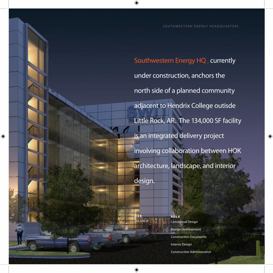
S I Z E134,500 sf
R O L EConceptual Design
Design Development
Construction Documents
Interior Design
Construction Administration
S O U T H W E S T E R N E N E R G Y H E A D Q U A R T E R S
Southwestern Energy HQ , currently
under construction, anchors the
north side of a planned community
adjacent to Hendrix College outisde
Little Rock, AR. The 134,000 SF facility
is an integrated delivery project
involving collaboration between HOK
architecture, landscape, and interior
design.

PR OJ EC T H I G H LI G H T S
• A 70’ wide, nearly 400’ long floorplate oriented along an East-West axis provides ideal conditions for the use of natual daylight.
• The building’s location within a masterplaned district of the Hendrix College Campus required consistency with traditional campus
aesthetics and materials on 3 facades of the building.
• A Combination of site design, a unique floorplate, high performance envelope and building systems, and local materials allowed for the facility to comfortably achieve LEED Gold requirements .
COS T$15 million (core & shell)
$7 million (tenant fit-out)
AWAR DSLEED Gold NC (pending)
LEED Gold CI (pending)
Utilizing Building Information System modeling and integrated project delivery allowed for the project to be delivered in an extremely efficient manner. B.I.M. modeling from the concept stage allowed for several design options to be presented in parallel through the schematic design phase. Permitting documents for the base building were released four months after concept work began, with construction work complete in approximately 12 months. Integrated project delivery allowed for consistent project team members across disciplines, resulting in efficient document production and conisistent execution of design intent.
Rendered Site Plan by HOK Planning Group
adamjspitz.com
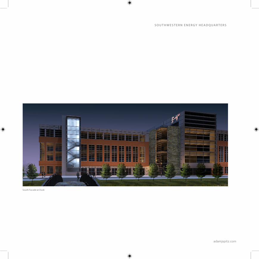
S O U T H W E S T E R N E N E R G Y H E A D Q U A R T E R S
South Facade at Dusk

Ground Level Floor PlanSouth Facade Section
Office Level Floor Plan

adamjspitz.com
East Elevation North Elevation
South ElevationWest Elevation
S O U T H W E S T E R N E N E R G Y H E A D Q U A R T E R S

Central Stair
adamjspitz.com
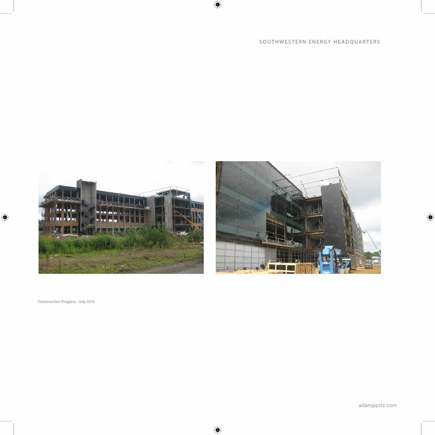
Construction Progress - July 2010
S O U T H W E S T E R N E N E R G Y H E A D Q U A R T E R S
LOREM IPSUM dolor sit
amet, consectetur adipisic-
ing elit,
sed do eiusmod tempor
incididunt ut labore et
dolore magna aliqua.
SIT DOLORW Ut enim ad minim
veniam, quis nostrud exercitation
adamjspitz.com
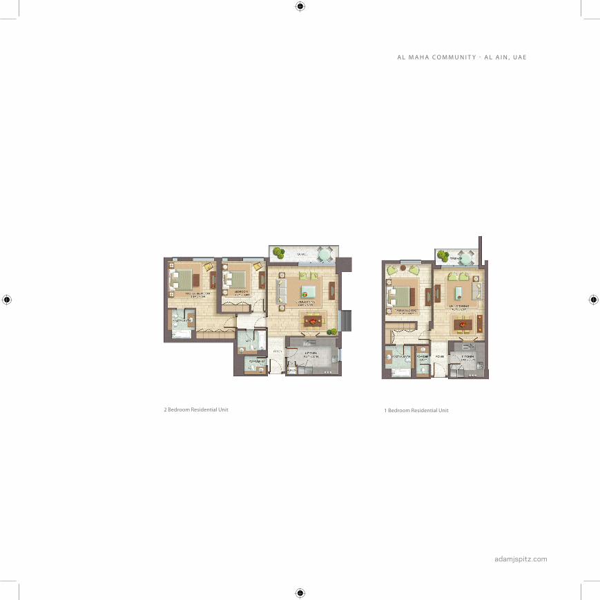
A L M A H A C O M M U N I T Y - A L A I N , U A E
SIT DOLORW Ut enim ad minim veniam, quis
nostrud exercitation ullamco laboris nisi ut aliquip
ex ea commodo consequat.
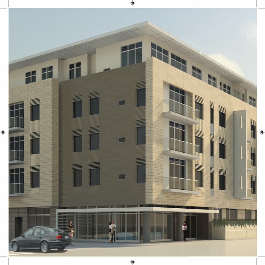
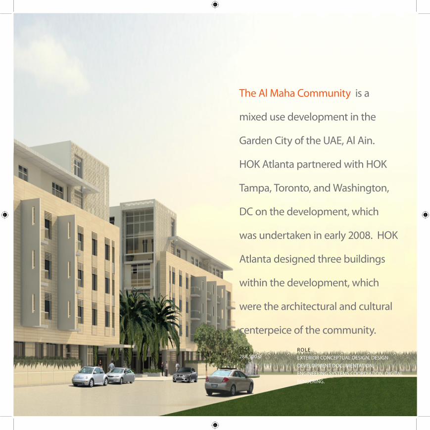
The Al Maha Community is a
mixed use development in the
Garden City of the UAE, Al Ain.
HOK Atlanta partnered with HOK
Tampa, Toronto, and Washington,
DC on the development, which
was undertaken in early 2008. HOK
Atlanta designed three buildings
within the development, which
were the architectural and cultural
centerpeice of the community.SIZE288,500 sf
R O LE EXTERIOR CONCEPTUAL DESIGN, DESIGN DEVELOPMENT DOCUMENTATION, ENGINEERING SYSTEMS COORDIATION, DIGITAL RENDERING.
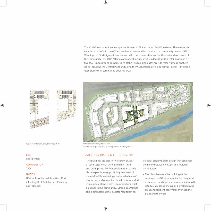
The Al Maha community encompasses 79 acres in Al, Ain, United Arab Emeriates. The master plan includes a mix of mid rise offices, residential towers, villas, retail, and a community center. HOK Washington, DC designed the office and villa components that anchor the east and west ends of the community. The HOK Atlanta component includes 152 residential units, a retail base, and a two level underground carpark. Each of the two building bases provide retail frontage on three sides, including the Central Plaza and along the Wadi Arcade, giving buildings 10 and 11 the stron-gest presence in community oriented areas.
BU I LD I N GS 10A , 10 B , 11 H I G H LI G H T S
• The buildings are clad in two earthy shades of terra cotta which define a distinct inner and outer plane. Perforated aluminum panels clad the penthouses, providing a contrast of material, while maintaing a delicate balance of proportion and geometry. Retail spaces are clad in a regional stone which is common to several buildings in the community. Strong geometries and a neutural material pallette resulted in an
elegant, contemporary design that acheived a balance between western and regional architecture.
• The plaza between the buildings is the centerpeice of the community, housing retail, restaurants, and a pedestrian connection to the retail arcade along the Wadi. Elevated dining areas and resident courtyards overlook the plaza and the Wadi.
COS TConfidential
CO M PLE T I O NTBD
N OT E SHOK multi-office collaborative effort, inlcuding HOK Architecture, Planning, and Interiors.
Al Maha Community Master PlanTypical Residential Level, Buildings 10-11Rendered site plan by HOK Planning Group, Washington, DC
adamjspitz.com
A L M A H A C O M M U N I T Y - A L A I N , U A E
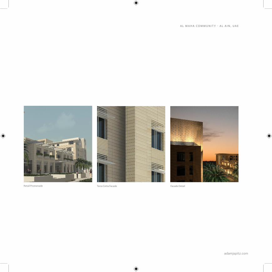
Terra Cotta Facade Facade DetailRetail Promenade
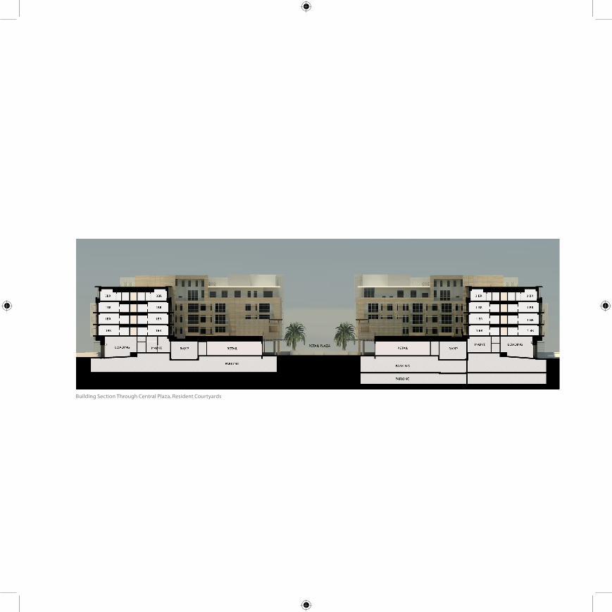
Building Section Through Central Plaza, Resident Courtyards
adamjspitz.com
A L M A H A C O M M U N I T Y - A L A I N , U A E
1 Bedroom Residential Unit2 Bedroom Residential Unit

CENTRAL COURTYARD is the focal point of the develop-
ment, containing multi-level retail, food and bevarage
outlets, community ammenity space, and resident
courtyards.
REVITALIZED MARTA FIVE POINTS STA-
TION PROVIDES CRITICAL LINK TO THE
REGIONAL TRANSPORTATION NETWORK
THE MASTER PLAN ENVISIONS OVER 4,000,000 SF OF
COMMERCIAL OFFICE DEVELOPMENT POTENTIAL IN
THE CORRIDOR
THE PROJECT CENTERPEICE IS THE MULTI-MODAL PASSENGER TERMINAL,
BRINGING COMMUTER RAIL, AMTRAK, MARTA OPERATIONS, AND REGIONAL
BUS SERVICES TO ONE CENTRAL LOCATION, ADJACENT TO EXISTING MASS
TRANSIT HUB
RETAIL AND HOTEL DEVELOPMENT
CONCENTRATED NEAR EXISTING
ARENA, STADIUM, AND CONVENTION
FACILITIES.
Rendered Site Plan by HOK Planning Group

adamjspitz.com
T H E G R E E N L I N E - AT L A N TA , G A , U S A
R O L E
MASTER PLAN DOCUMENTATION, DIGITAL
RENDERING, CONCEPTUAL DESIGN (MULTI-MODAL
TRANSIT TERMINAL & OFFICE TOWER)
The Green Line is an ambitious plan
for revitalization and growth in
Downtown Atlanta. The master plan
encompasses 94 acres, creating new
green space over existing freight
rail corridors, new commercial,
retail, residential and entertainment
development opportunities, and a
multi-modal transit terminal that is
the hub of a proposed state wide
transportation networkSIZE
94 ACRES (07)
7,400,000+ SF
CENTRAL COURTYARD is the focal point of the develop-
ment, containing multi-level retail, food and bevarage
outlets, community ammenity space, and resident
courtyards.
580 STUDENT HOUSING UNITS -
GEORGIA STATE UNIVERSITY
CONTINUOUS LINEAR GREENSPACE ENCOMPASSING 15
ACRES LINKS THE STATE CAPITAL AND GEORGIA STATE
UNVERSITY TO THE EAST WITH THE GEORGIA DOME
AND WORLD CONGRESS CENTER TO THE WEST
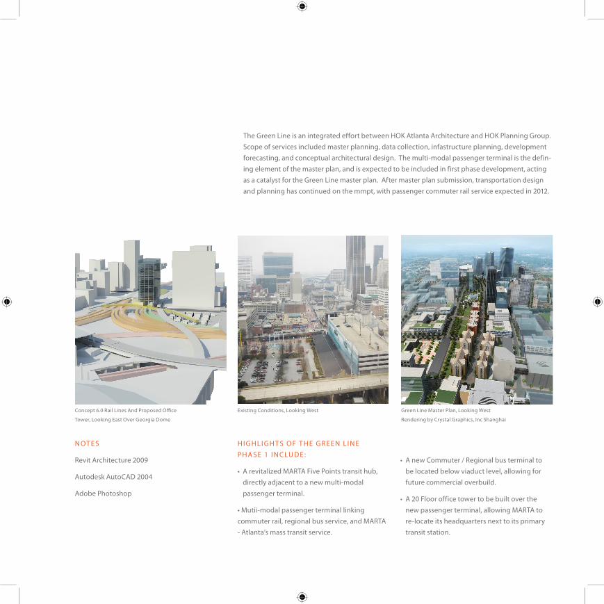
The Green Line is an integrated effort between HOK Atlanta Architecture and HOK Planning Group. Scope of services included master planning, data collection, infastructure planning, development forecasting, and conceptual architectural design. The multi-modal passenger terminal is the defin-ing element of the master plan, and is expected to be included in first phase development, acting as a catalyst for the Green Line master plan. After master plan submission, transportation design and planning has continued on the mmpt, with passenger commuter rail service expected in 2012.
H I G H LI G H T S O F T H E G R EEN L I N E PHA SE 1 I N CLU D E :
• A revitalized MARTA Five Points transit hub, directly adjacent to a new multi-modal passenger terminal.
• Mutii-modal passenger terminal linking commuter rail, regional bus service, and MARTA - Atlanta’s mass transit service.
• A new Commuter / Regional bus terminal to be located below viaduct level, allowing for future commercial overbuild.
• A 20 Floor office tower to be built over the new passenger terminal, allowing MARTA to re-locate its headquarters next to its primary transit station.
N OT E S
Revit Architecture 2009
Autodesk AutoCAD 2004
Adobe Photoshop
Green Line Master Plan, Looking West
Rendering by Crystal Graphics, Inc Shanghai
Existing Conditions, Looking West Concept 6.0 Rail Lines And Proposed Office
Tower, Looking East Over Georgia Dome

adamjspitz.com
A N D R E A D I CK EN S
Dean of Students,
William Rainey Harper College
T H E G R E E N L I N E - AT L A N TA , G A , U S A
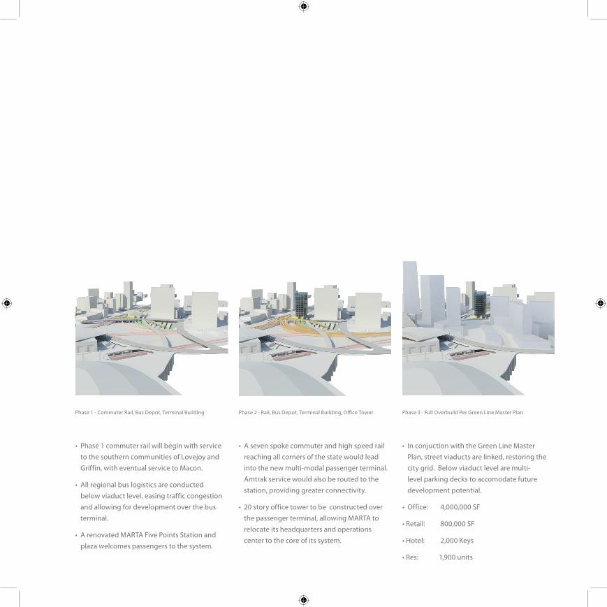
• Phase 1 commuter rail will begin with service to the southern communities of Lovejoy and Griffin, with eventual service to Macon.
• All regional bus logistics are conducted below viaduct level, easing traffic congestion and allowing for development over the bus terminal.
• A renovated MARTA Five Points Station and plaza welcomes passengers to the system.
• A seven spoke commuter and high speed rail reaching all corners of the state would lead into the new multi-modal passenger terminal. Amtrak service would also be routed to the station, providing greater connectivity.
• 20 story office tower to be constructed over the passenger terminal, allowing MARTA to relocate its headquarters and operations center to the core of its system.
• In conjuction with the Green Line Master Plan, street viaducts are linked, restoring the city grid. Below viaduct level are multi-level parking decks to accomodate future development potential.
• Office: 4,000,000 SF
• Retail: 800,000 SF
• Hotel: 2,000 Keys
• Res: 1,900 units
Phase 1 - Commuter Rail, Bus Depot, Terminal Building Phase 3 - Full Overbuild Per Green Line Master PlanPhase 2 - Rail, Bus Depot, Terminal Building, Office Tower
adamjspitz.com
T H E G R E E N L I N E - AT L A N TA , G A , U S A
Multi-Modal Logistics Diagram
TERMINAL HALL
BUS TERMINAL
MARTA HQ TOWER
PHASE 1 COMMUTER RAIL
PHASE 2 COMMUTER RAIL
MARTA 5 POINTSSTATION
SPRING ST. VIADUCT
PHASE 3 H
IGH
SPEED RAIL
ALABAMA ST VIADUCT
MARTA E-W
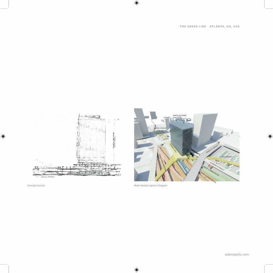
Concept Section

Rendering by Crystal Graphics, Inc - Shanghai
adamjspitz.com
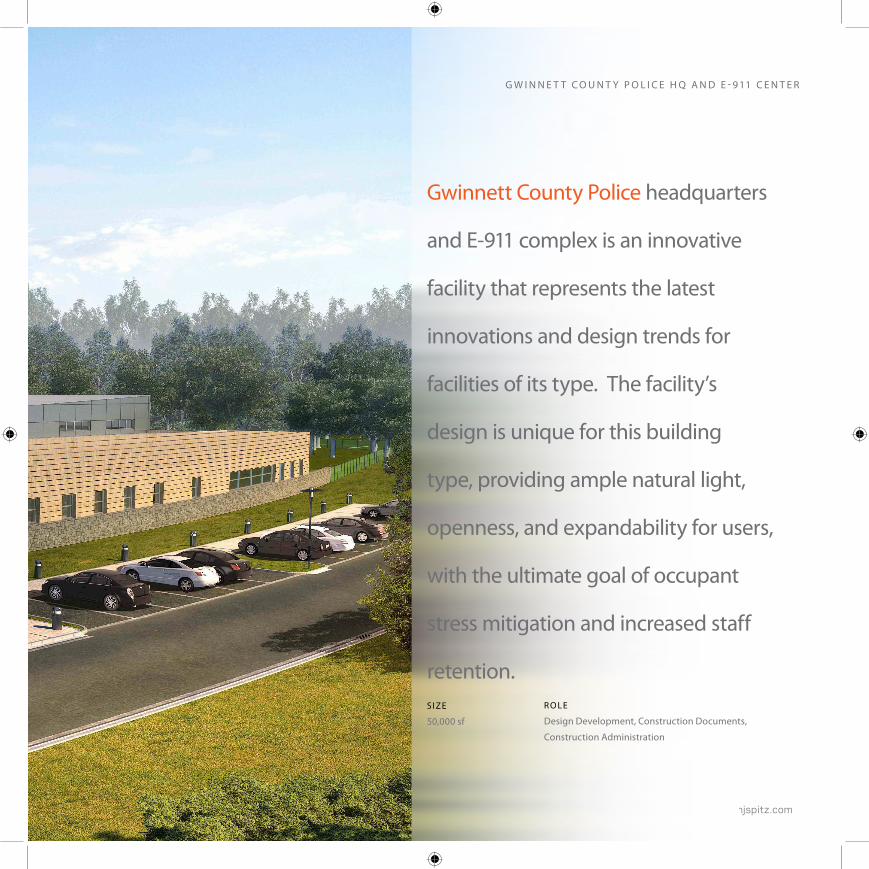
Gwinnett County Police headquarters
and E-911 complex is an innovative
facility that represents the latest
innovations and design trends for
facilities of its type. The facility’s
design is unique for this building
type, providing ample natural light,
openness, and expandability for users,
with the ultimate goal of occupant
stress mitigation and increased staff
retention.SIZE
50,000 sf
R O L E
Design Development, Construction Documents,
Construction Administration
G W I N N E T T C O U N T Y P O L I C E H Q A N D E - 9 11 C E N T E R
Project Highlights:
• 10,000 SF 911 call center accomodating 40 call takers with adjacent 311 support
• 3,000 SF emergency operations center
• 9,000 SF police headquarters annex
• 4,000 SF data center
• Technical challenges include hardened construction requirements (FEMA 361) integration of redudant` building systems, specialized systems to accomodate data center requirements (including FM200), stringent building security requirements, and over 15,000 SF of access flooring systems within sealed areas.
COS T$18 million
CO M PLE T I O NNovember 2009
AWAR DSACI ‘Design Award of Excellence’
ABC ‘Award of Excellence’
N OT E SRevit Architecture 2008, 2009
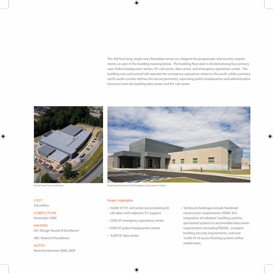
Employee Entrance And Emergency Operations CenterAerial View From Southeast
The 300 foot long, single story floorplate serves as a diagram for programatic and security require-ments, as seen in the building massing below. The building floor plan is divided among four primary uses: Police headquarters annex, 911 call center, data center, and emergency operations center. The building core and central hall seperate the emergency operations center to the south, while a primary north-south corridor defines the secure perimeter, seperating police headquarters and administrative functions from the builidng data center and 911 call center.

adamjspitz.com
Floor Plan Diagram
G W I N N E T T C O U N T Y P O L I C E H Q A N D E - 9 11 C E N T E R
POLICE HQ / ADMINISTRATION
DATA CENTER
SUPPORT
EOC911
PUBLIC ENTRANCE
STAFF ENTRANCE

Public Entrance Emergency Operations CenterPublic Lobby
adamjspitz.com
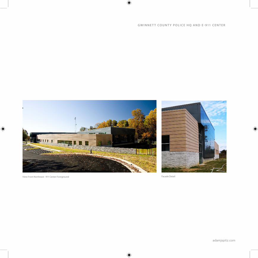
View From Northeast - 911 Center Foreground Facade Detail
G W I N N E T T C O U N T Y P O L I C E H Q A N D E - 9 11 C E N T E R
H O K A T L A N T A P R O J E C T S
adamjspitz.com
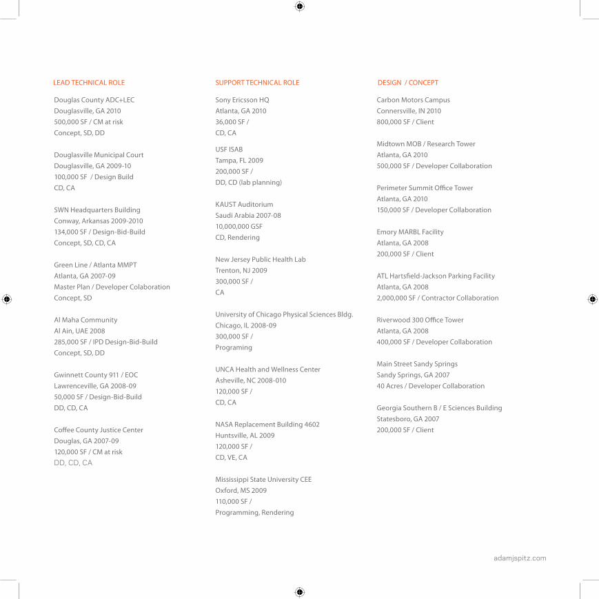
Douglas County ADC+LECDouglasville, GA 2010500,000 SF / CM at risk Concept, SD, DD
Douglasville Municipal Court Douglasville, GA 2009-10 100,000 SF / Design BuildCD, CA
SWN Headquarters BuildingConway, Arkansas 2009-2010 134,000 SF / Design-Bid-BuildConcept, SD, CD, CA
Green Line / Atlanta MMPT Atlanta, GA 2007-09 Master Plan / Developer ColaborationConcept, SD
Al Maha Community Al Ain, UAE 2008285,000 SF / IPD Design-Bid-BuildConcept, SD, DD
Gwinnett County 911 / EOC Lawrenceville, GA 2008-09 50,000 SF / Design-Bid-BuildDD, CD, CA
Coffee County Justice Center Douglas, GA 2007-09 120,000 SF / CM at riskDD, CD, CA
Sony Ericsson HQ Atlanta, GA 2010 36,000 SF / CD, CA
USF ISAB Tampa, FL 2009 200,000 SF /DD, CD (lab planning)
KAUST Auditorium Saudi Arabia 2007-08 10,000,000 GSF CD, Rendering
New Jersey Public Health Lab Trenton, NJ 2009 300,000 SF / CA
University of Chicago Physical Sciences Bldg. Chicago, IL 2008-09300,000 SF / Programing
UNCA Health and Wellness Center Asheville, NC 2008-010120,000 SF /CD, CA
NASA Replacement Building 4602 Huntsville, AL 2009120,000 SF / CD, VE, CA
Mississippi State University CEE Oxford, MS 2009110,000 SF / Programming, Rendering
Carbon Motors CampusConnersville, IN 2010800,000 SF / Client
Midtown MOB / Research TowerAtlanta, GA 2010500,000 SF / Developer Collaboration
Perimeter Summit Office TowerAtlanta, GA 2010150,000 SF / Developer Collaboration
Emory MARBL FacilityAtlanta, GA 2008200,000 SF / Client
ATL Hartsfield-Jackson Parking FacilityAtlanta, GA 20082,000,000 SF / Contractor Collaboration
Riverwood 300 Office TowerAtlanta, GA 2008400,000 SF / Developer Collaboration
Main Street Sandy SpringsSandy Springs, GA 200740 Acres / Developer Collaboration
Georgia Southern B / E Sciences BuildingStatesboro, GA 2007200,000 SF / Client
LEAD TECHNICAL ROLE SUPPORT TECHNICAL ROLE DESIGN / CONCEPT
02-07S E L E C T E D P R O J E C T S
NBA / NHL ARENA - MILWAUKEE, WI
STOCKHOLM PUBLIC LIBRARY
adamjspitz.com
02-07T H E U N I V E R S I T Y O F T E N N E S S E E
KNOXVILLE, TENNESSEE
A U G U S T 2 0 0 2 - M A Y 2 0 0 7


adamjspitz.com
SIZE
350,000 sf
R O L E
Programming, NBA/NHL Facility Standards study,
Design
N B A / N H L A R E N A - M I L W A U K E E , W I
NBA / NHL Arena addressed the
current trends and the potential of
arena design in a vibrant downtown
setting. The building design seeks
to exploit location to increase
opportunities for revenue generation
outisde of standard operating
schedules. The design is both
functional and sculptural, built on
industry standards, while creating a
unique experience both inside and out.

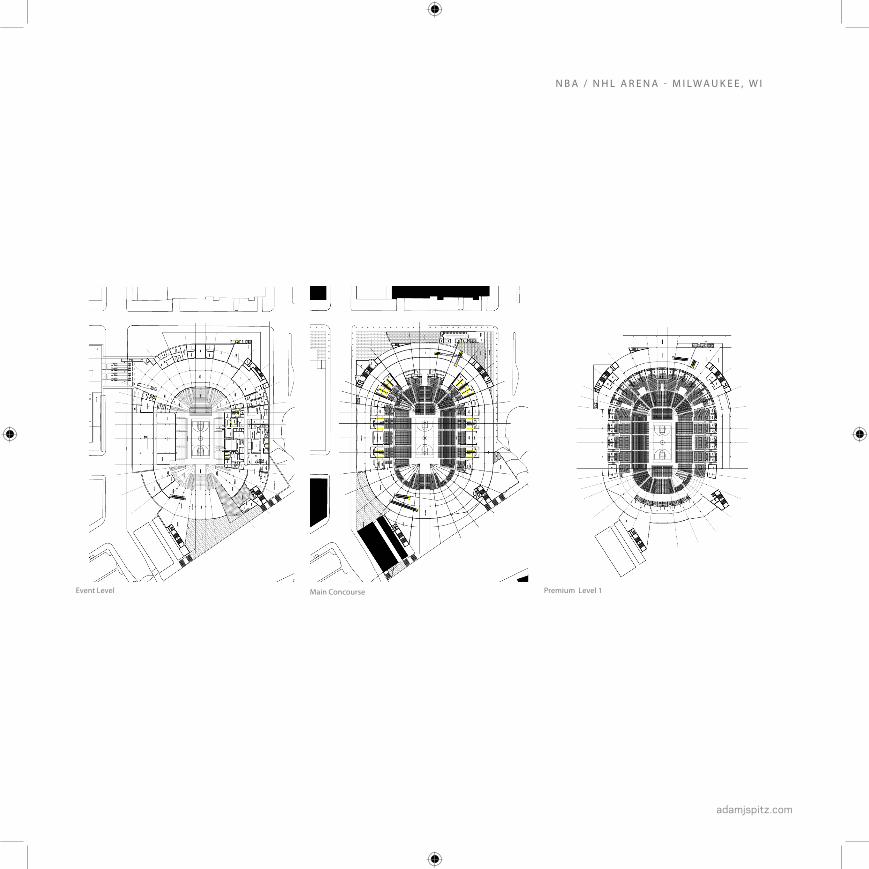
The arena’s location on the Milwaukee Riverfront provided a unique design opportunity and a num-ber of challenges. Historical context, the Milwaukee Riverwalk, and proximity to existing sports and convention facilities provides a dynamic environment for entertainment. The event level and it’s as-sociated amenities are located at the Riverwalk level, allowing for continuous operation of riverfront retail, with a unique view into the arena bowl.The seating bowl was designed for hockey, basketball, and theater configurations using a combination of portable and variable riser seating systems below the main concourse level.
Arena Design Highlights
• Full programming of arena facility, including
conformance with NBA/NHL facility standards,
with consultation from sports architects across
several globally recognized firms.
• Technical approach to project, focusing on facility
operations, full sightline studies in multiple
seating configurations, constructability, and
facility specific product research.
• Scheduling/quantification of critical components
such as seat types, precast risers, and fixtures.
• Compact site along riverfront in context of
historic buildings drove inital planning of levels,
concourses, operational logistics, and vomitory
configuration.
Site Physical Model - Seating Bowl and Roof Structure
DAT E
2006-2007
N OT E S
Autodesk AutoCAD 2004, Form Z, Adobe
Photoshop, Adobe Indesign, Esri ArcGIS
UT School Of Architecture Design Award
adamjspitz.com
Event Level Main Concourse Premium Level 1
N B A / N H L A R E N A - M I L W A U K E E , W I
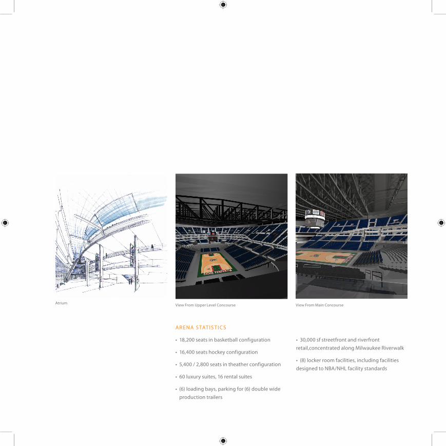
AR ENA S TAT IS T I C S
• 18,200 seats in basketball configuration
• 16,400 seats hockey configuration
• 5,400 / 2,800 seats in theather configuration
• 60 luxury suites, 16 rental suites
• (6) loading bays, parking for (6) double wide production trailers
• 30,000 sf streetfront and riverfront retail,concentrated along Milwaukee Riverwalk
• (8) locker room facilities, including facilities designed to NBA/NHL facility standards
Atrium View From Upper Level Concourse View From Main Concourse
adamjspitz.com
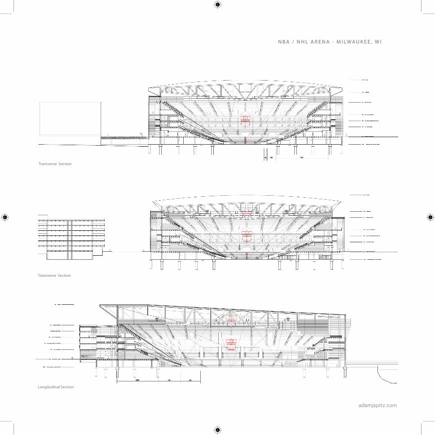
N B A / N H L A R E N A - M I L W A U K E E , W I
Longitudinal Section
Transverse Section
Transverse Section

JANE SOMEONE
AIA, LEED® AP
Architect
PATRICK SOMEONE
Interior Design | FFE Specifications |
Artwork Programs
adamjspitz.com
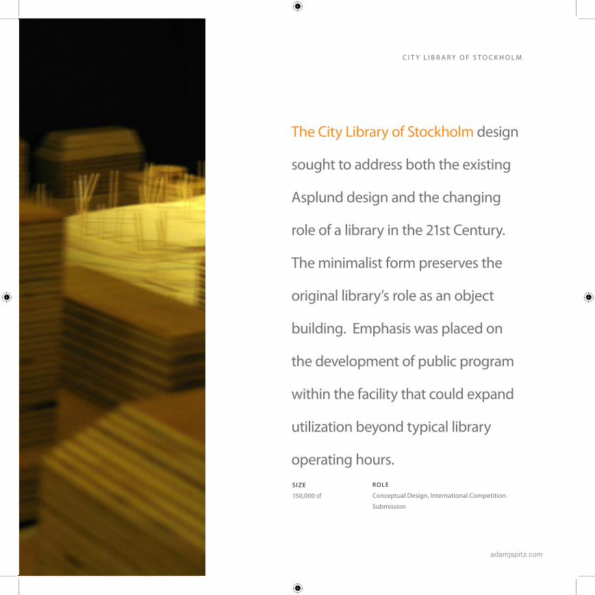
The City Library of Stockholm design
sought to address both the existing
Asplund design and the changing
role of a library in the 21st Century.
The minimalist form preserves the
original library’s role as an object
building. Emphasis was placed on
the development of public program
within the facility that could expand
utilization beyond typical library
operating hours.
SARAH SOMEONE
AIA, LEED® AP
Project Manager | Vice President
S IZE
150,000 sf
R O L E
Conceptual Design, International Competition
Submission
C I T Y L I B R A R Y O F S T O C K H O L M

Library Design Highlights
• Potential 24 hour Public Program, including a media center, cafe, periodicals, and music collections are located in an atrium space along the plaza beneath the collections area, enabling these spaces to remain active, while maintaining security for the collections area, accessed by elevators. A bridge from the atrium serves as the link to the historical library, which is to house
the rare book and archive collection.
• The linear design concept provides an efficient and logical method for organizing library media. The primary building mass is aligned to, but offset from the original building axis. The resulting geometry complements the simple geometries of the original Asplund building.
Floor Plans Diagram - LogisticsDiagram - Public / Operations
PUBL
IC E
LEVA
TOR
(TO
CH
ECKO
UT)
PUBLIC
MAIN DEPOSITORY
MEDIA
(PLAZA)
FREI
GH
T EL
EVAT
OR
(TO
STA
CKS)
LOADING DOCK
PROGRAM
MANAGEMENT
DEPOSITORY
DAT E2006
N OT E SAutodesk AutoCAD 2004, Form Z, Adobe Indesign
Submitted for Inernational Competition

adamjspitz.com
Public Atrium / Connecting Bridge Overall View
C I T Y L I B R A R Y O F S T O C K H O L M


adamjspitz.com
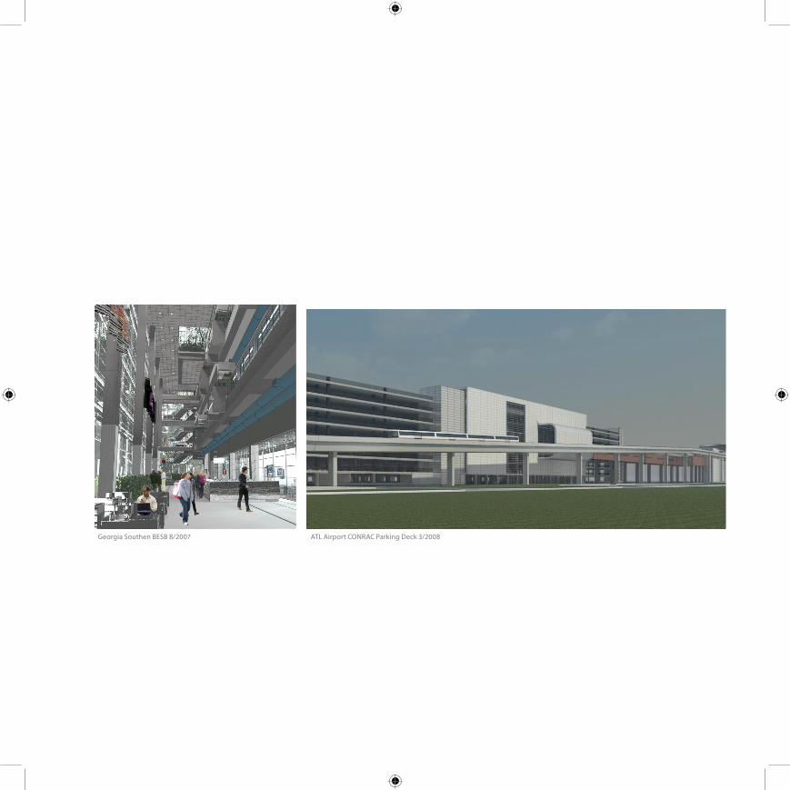
Georgia Southen BESB 8/2007 ATL Airport CONRAC Parking Deck 3/2008

adamjspitz.com
Carbon Motors 3/2010 Perimeter Summit 4/2010
C O N C E P T D E S I G N - H O K