adana btÜ ders katalog formu (course ... plan week topics chapters 1 basic behaviors of concrete,...
TRANSCRIPT
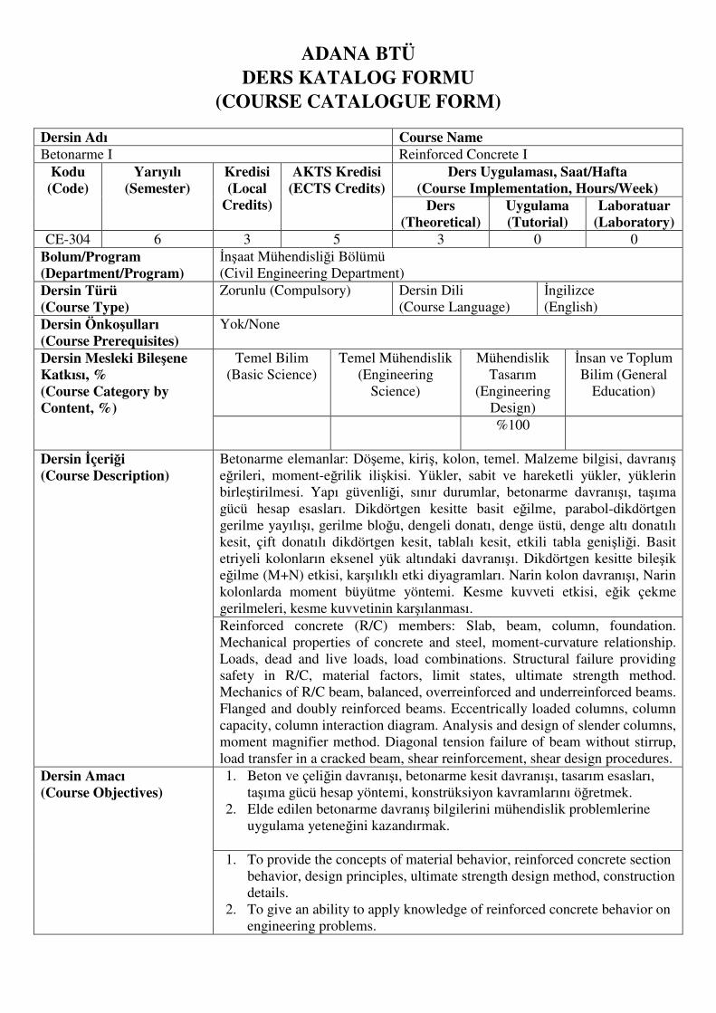
ADANA BTÜ DERS KATALOG FORMU
(COURSE CATALOGUE FORM)
Dersin Adı Course Name Betonarme I Reinforced Concrete I
Kodu (Code)
Yarıyılı (Semester)
Kredisi (Local
Credits)
AKTS Kredisi (ECTS Credits)
Ders Uygulaması, Saat/Hafta (Course Implementation, Hours/Week)
Ders (Theoretical)
Uygulama (Tutorial)
Laboratuar (Laboratory)
CE-304 6 3 5 3 0 0
Bolum/Program (Department/Program)
İnşaat Mühendisliği Bölümü
(Civil Engineering Department)
Dersin Türü (Course Type)
Zorunlu (Compulsory) Dersin Dili
(Course Language)
İngilizce
(English)
Dersin Önkoşulları (Course Prerequisites)
Yok/None
Dersin Mesleki Bileşene Katkısı, % (Course Category by Content, %)
Temel Bilim
(Basic Science)
Temel Mühendislik
(Engineering
Science)
Mühendislik
Tasarım
(Engineering
Design)
İnsan ve Toplum
Bilim (General
Education)
%100
Dersin İçeriği (Course Description)
Betonarme elemanlar: Döşeme, kiriş, kolon, temel. Malzeme bilgisi, davranış eğrileri, moment-eğrilik ilişkisi. Yükler, sabit ve hareketli yükler, yüklerin
birleştirilmesi. Yapı güvenliği, sınır durumlar, betonarme davranışı, taşıma
gücü hesap esasları. Dikdörtgen kesitte basit eğilme, parabol-dikdörtgen
gerilme yayılışı, gerilme bloğu, dengeli donatı, denge üstü, denge altı donatılı
kesit, çift donatılı dikdörtgen kesit, tablalı kesit, etkili tabla genişliği. Basit
etriyeli kolonların eksenel yük altındaki davranışı. Dikdörtgen kesitte bileşik
eğilme (M+N) etkisi, karşılıklı etki diyagramları. Narin kolon davranışı, Narin
kolonlarda moment büyütme yöntemi. Kesme kuvveti etkisi, eğik çekme
gerilmeleri, kesme kuvvetinin karşılanması.
Reinforced concrete (R/C) members: Slab, beam, column, foundation.
Mechanical properties of concrete and steel, moment-curvature relationship.
Loads, dead and live loads, load combinations. Structural failure providing
safety in R/C, material factors, limit states, ultimate strength method.
Mechanics of R/C beam, balanced, overreinforced and underreinforced beams.
Flanged and doubly reinforced beams. Eccentrically loaded columns, column
capacity, column interaction diagram. Analysis and design of slender columns,
moment magnifier method. Diagonal tension failure of beam without stirrup,
load transfer in a cracked beam, shear reinforcement, shear design procedures.
Dersin Amacı (Course Objectives)
1. Beton ve çeliğin davranışı, betonarme kesit davranışı, tasarım esasları,
taşıma gücü hesap yöntemi, konstrüksiyon kavramlarını öğretmek.
2. Elde edilen betonarme davranış bilgilerini mühendislik problemlerine
uygulama yeteneğini kazandırmak.
1. To provide the concepts of material behavior, reinforced concrete section
behavior, design principles, ultimate strength design method, construction
details.
2. To give an ability to apply knowledge of reinforced concrete behavior on
engineering problems.

Dersin Öğrenme Çıktıları (Course Learning Outcomes)
Bu dersi başarıyla geçen öğrenciler aşağıdaki konularda bilgi ve beceri kazanır.
1. Betonarme elemanlarda kullanılan malzemeler, betonarme davranışı, 2. Betonarme elemanlarda basit, bileşik eğilme (M, N+M) etkileri altında
davranış ve tasarım,
3. Narin kolon davranışı ve tasarımı,
4. Betonarme elemanların kesme etkisi altındaki davranışı ve tasarımı,
5. Donatı konstrüksiyonu.
Students completing this course will gain knowledge on:
1. Materials of reinforced concrete, behavior of reinforced concrete,
2. Behavior of reinforced concrete members subjected to M or N+M effects
and their design,
3. Behavior and design of slender columns,
4. Behavior of reinforced concrete members subjected to shear and their
design,
5. Reinforcement construction.
Ders Kitabı (Textbook)
Wight, J.K., MacGregor, J.G. Reinforced Concrete, Mechanics and Design
6th Edition, Pearson, 2012. ISBN 10:0-273-76454-3.
Diğer Kaynaklar (Other References)
1. TS500 Betonarme Yapıların Hesap ve Yapım Kuralları, 2000.
2. Deprem Bölgelerinde Yapılacak Yapılar Hakkında Yönetmelik, 2007.
3. Doğangün, A., Betonarme Yapıların Hesap ve Tasarımı, Birsen Yayınevi,
2013. ISBN: 9789755113104.
4. Celep, Z., Kumbasar, N., Betonarme Yapılar, Beta Dağıtım, İstanbul, 2009.
5. Atımtay, E., Reinforced Concrete, Vol.1&Vol.2 Bizim Büro Basımevi,
Ankara, 1998.
Ödevler ve Projeler (Homework & Projects)
7 Uygulama (Sınıfta yapılacak)
7 Recitations (will be held in class)
Başarı Değerlendirme Sistemi (Assesment Criteria)
Faaliyetler (Activities)
Adedi – En az (Quantity – Minimum)
Değerlendirme Katkısı % (Effects on Grading %)
Yıliçi Sınavları (Midterm Exams)
1 %35
Ödevler (Homeworks)
1 %5
Uygulamalar (Recitations)
7 -
Final Sınavı (Final Exam)
1 %60
COURSE PLAN
Week Topics Chapters 1 Basic Behaviors of Concrete, Steel and Reinforced Concrete, Moment
Curvature Relationship, Types of Failure in Reinforced Concrete Members,
Ultimate Strength Theory (Flexure and Axial Load), Safety Provisions in
TS500, Load and material factors.
1,2,3
2 Ultimate Strength of Members Subjected to Flexure, Tension Failure,
Compression Failure, Balanced, Underreinforced and Overreinforced Beams.
Practices.
4
3 Ultimate Moment Capacity of Double Reinforced Rectangular Beam Sections.
Ultimate Moment Capacity of Flanged Beam Sections. Practices. 4
4 Design of Single, Double Reinforced Rectangular and Flanged Beam Sections.
Minimum Requirements for Beams. 5
5 Design of Single, Double Reinforced Rectangular and Flanged Beam Sections.
Minimum Requirements for Beams. Practices. 5
6 Combined Flexure and Axial Load, Reinforced Concrete Columns. Ultimate
Strength of RC Sections Subjected to Axial Force and Flexure. Interaction
Diagrams.
11
7 Combined Flexure and Axial Load, Reinforced Concrete Columns. Rectangular
Sections Having Symmetrical Steel on Two Faces Only. Practices 11
8 MIDTERM WEEK 9 Design of Short Columns, Design Charts, Slenderness Effects (Second Order
Moments), Flexural Rigidity, Effective Length of Columns. 11,12
10 Design Methods for Calculating Second Order Moments, Moment
Magnification Method, Minimum Requirements for Columns. 12
11 Design Methods for Calculating Second Order Moments, Moment
Magnification Method, Minimum Requirements for Columns. Practices. 12
12 Shear-Diagonal Tension, Behavior and Strength of Beams without Shear
Reinforcement, Diagonal Cracking Strength, Behavior and Strength of Beams
with Shear Reinforcement, Truss Analogy for Beam with Shear Reinforcement.
6
13 Design for Shear. Practices. 6 14 General Review.

REINFORCED CONCRETE - I
RECITATION 1
1-)
For the singly reinforced rectangular beam section, shown above, determine the ultimate
moment capacity, M�. The beam section is made of concrete with a compressive strength, C20
and has 4Φ22 bars with a steel grade, S420. The modulus of elasticity of the steel is
E� = 2. 10�[MPa] and clear cover, d� = 40[mm]. 2-)
A simply supported beam and the cross-section at midspan is shown above in the figure. The
beam supports a uniform service (unfactored) dead load g=20[kN/m] and a concentrated service
(unfactored) live load of Q=15[kN]. The concrete strength, f�� = 20[MPa], f��� = 1.04[MPa] and the characteristic yield strength, σ�� = 420[MPa]. Design flexural reinforcement, A� of
the beam for the design moment, M� obtained by using load factors from TS498. E� =2. 10�[MPa] and clear cover, d� = 40[mm].
REINFORCED CONCRETE - I
RECITATION 2
1-)
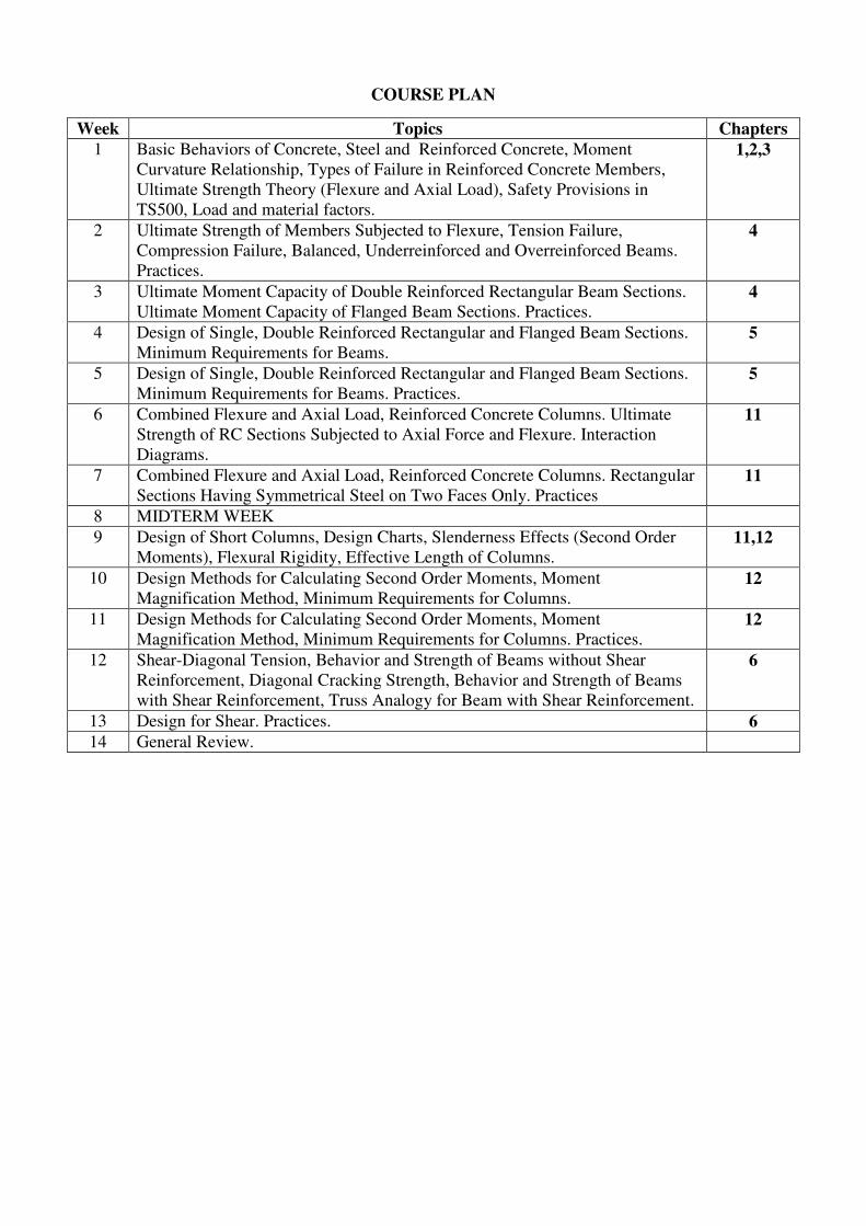
Compute the ultimate moment capacity, M� for the doubly reinforced rectangular beam, shown
above in the figure. 7Φ16 bars have been used as compression reinforcement. Assume that
d=440[mm] and the material properties are C20 and S420. Recall that E� = 2. 10�[MPa].
2-)
Design the rectangular beam section with the dimensions, shown above in the figure, to resist
a factored design moment, M� = 317.6[kNm]. Determine the tension steel reinforcement, A� by taking tension steel ratio, a) ! = ". #$%!& and b) ! = ". $!& where ρ( is the balanced ratio.
If it needs, determine the area of compression steel, A�� by assuming the material properties are
C20 and S420. Recall that E� = 2. 10�[MPa] and clear cover, d� = 40[mm].
REINFORCED CONCRETE - I
RECITATION 3
1-)
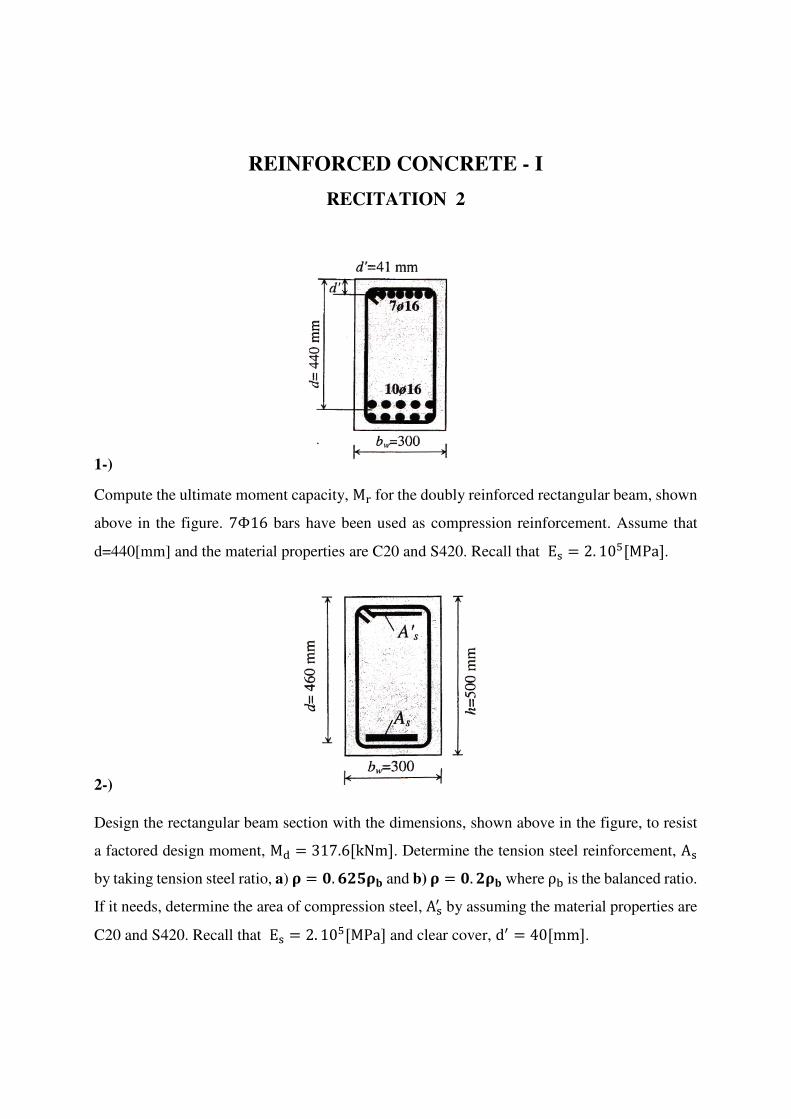
Compute the ultimate moment capacity, M� for the singly reinforced flanged beam section,
shown above in the figure. 6Φ14 bars have been used as tension reinforcement. Assume that
d=460[mm], b=800[mm] and b* = 250[mm] and the material properties are C20 and S420.
Recall that E� = 2. 10�[MPa].
2-)
Compute the ultimate moment capacity, M� for the singly reinforced flanged beam section,
shown above in the figure. 10Φ16 bars have been used as tension reinforcement. Assume that
d=440[mm], b=600[mm] and b* = 250[mm] and the material properties are C20 and S420.
Recall that E� = 2. 10�[MPa].

REINFORCED CONCRETE - I
RECITATION 4
1-)
Design the flanged beam section with the dimensions, shown above in the figure, to resist a
factored design moment, M� = 200[kNm]. Determine the tension steel reinforcement, A� and
check that the required steel ratio, ρ , 0.85ρ( and ρ . ρ/01 where ρ( is the balanced ratio.
Assume that the material properties are C20 and S420. Recall that E� = 2. 10�[MPa] and clear
cover, d� = 40[mm].
2-)
Design the flanged beam section with the dimensions, shown above in the figure, to resist a
factored design moment, M� = 300[kNm]. Determine the tension steel reinforcement, A� and
check that the required steel ratio, ρ , 0.85ρ( and ρ . ρ/01 where ρ( is the balanced ratio.
Assume that the material properties are C20 and S420. Recall that E� = 2. 10�[MPa] and clear
cover, d� = 40[mm].

REINFORCED CONCRETE - I
RECITATION 5
1-)
Determine the ultimate moment capacity 2M�3 of the symmetrically reinforced column, shown
above in the figure, under 3 different levels of axial design loads which are a) 456 = 7"[84] b) 45$ = 9""[84] and c)459 = #""[84]. As shown, the column is symmetrically reinforced
on two faces with a total steel area, A�� = 804.2[mm;]24Φ163. Assume that the materials are
C25 and S420. Recall that E� = 2. 10�[MPa] and clear cover, d� = 20[mm].
2-)
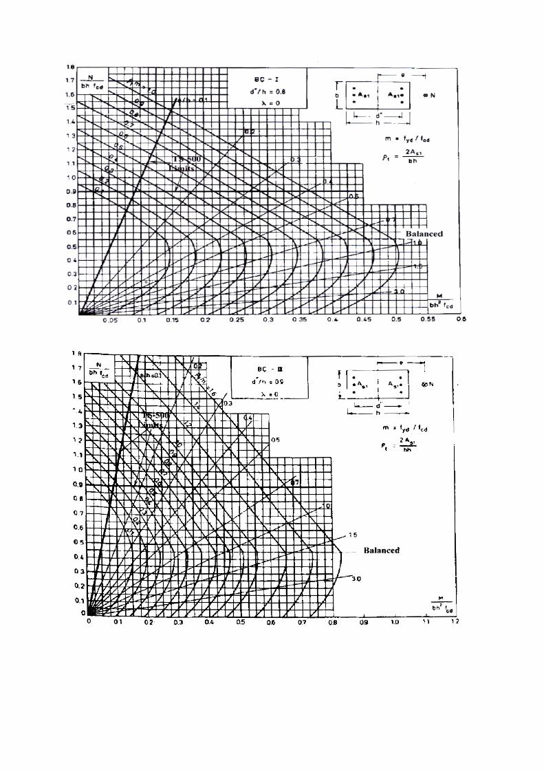
By using the appropriate interaction diagram, given in the next page, determine the required
total steel ratio 2A��3 of the short column shown above in the figure, to support the loads given
in the accompanying list. In each case, use C16 and S220.
a) N� = 1200[kN] and M� = 160[kNm] b) N� = 743[kN] and M� = 66.8[kNm]

REINFORCED CONCRETE - I
RECITATION 6
1-)
An interior column of the multistory frame and the moments on it are shown above in the figure. The dimensions are
center to center of the joints. The beams are 250x500 [mm] and columns are 400x400 [mm]. The building includes a
service core shear wall which resists the majority of the lateral loads. The loads and moments on the column are as:
M�<=> = 180[kNm], M�@=< = 200[kNm], N� = 3000[kN], NA� = 2400[kN] (a) Determine if the column is slender or not. (b) If the column is slender, determine the design moment of the column,
by using TS-500 moment magnifier method. Assume that the materials are C20, S220 and E� = 28[GPa] and the
equations for the slender columns are given below.
L�i , 34 E 12M�FM�; 2bracedframe3;L�i , 222unbracedframe3;L� = kL1
α = ∑OI LQ R�ST∑OI LQ R(UV/ ; N�� =π;EIL�; ; EI = E�I�2.5 X 11 Y R/[ ;R/ =
NA� N�\ 2Braced3orR/ = ∑VA� ∑V�\ 2Unbraced3
k = a0.7 Y 0.052αF Y α;30.85 Y 0.05αF1.0 b/01
2Bracedframe3
k = 20 E α/20 c1 Y α/2ifα/ d 2.03ork = 0.9c1 Y α/2ifα/ . 2.032Unbracedframe3 α/ = 0.52αF Y α;3
β = C/1 E 1.3 hN� N��Q i ;C/ = 0.6 Y 0.4M�F M�;⁄ . 0.4;M�; . M�F2Bracedframe3
β = 2β� β�ST3/Vk = a 1.01 E 1.3 h∑N� ∑N��\ i
1.01 E 1.3 hN� N��Q ib/Vk
2Unbracedframe3
REINFORCED CONCRETE - I
RECITATION 7
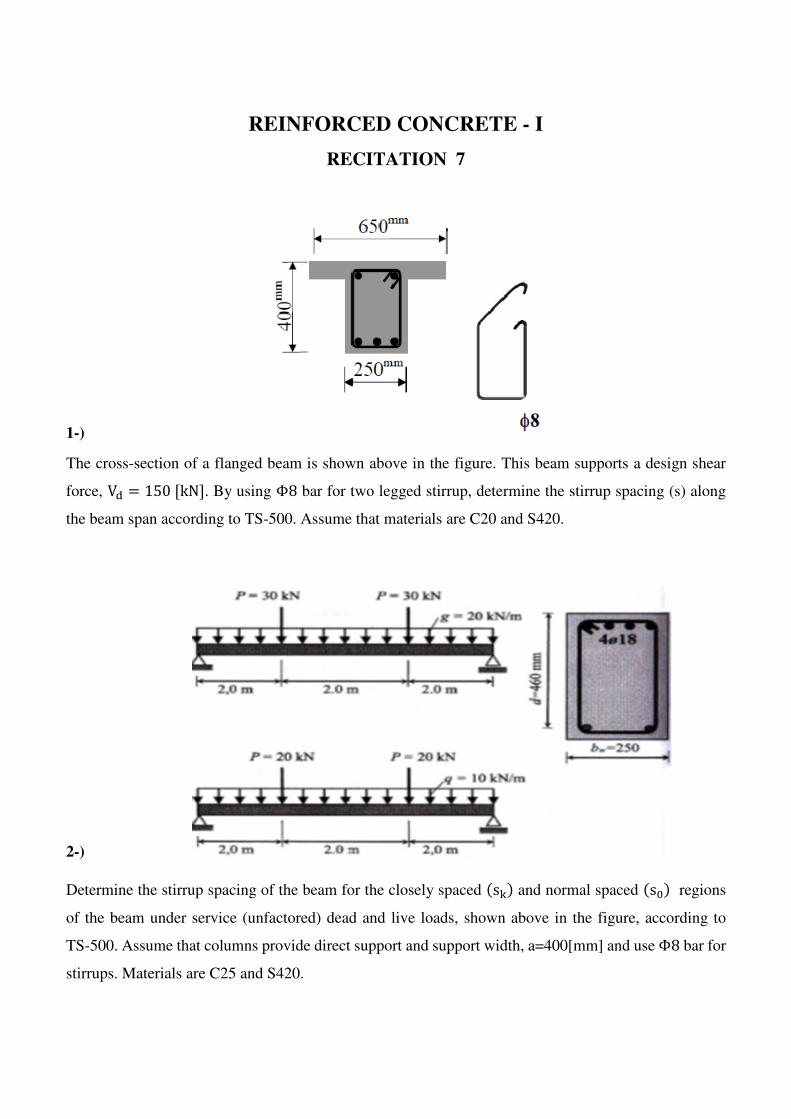
1-)
The cross-section of a flanged beam is shown above in the figure. This beam supports a design shear
force, V� = 150[kN]. By using Φ8 bar for two legged stirrup, determine the stirrup spacing (s) along
the beam span according to TS-500. Assume that materials are C20 and S420.
2-)
Determine the stirrup spacing of the beam for the closely spaced 2s�3 and normal spaced 2sm3 regions
of the beam under service (unfactored) dead and live loads, shown above in the figure, according to
TS-500. Assume that columns provide direct support and support width, a=400[mm] and use Φ8 bar for
stirrups. Materials are C25 and S420.