adapting a blowdown type wind tunnel for ground effect
TRANSCRIPT

Adapting a Blowdown Type Wind Tunnelfor Ground Effect Simulation Tests
RICHARD SELESCUDepartment of Aerodynamics
“Elie Carafoli” National Institute for Aerospace Research – INCASBucharest, Sector 6, Bd. Iuliu Maniu, No. 220, Code 061126
ROMANIA
Abstract: This paper shortly presents the main results of some researches regarding the adaptation of anintermittent (blowdown type) wind tunnel for testing models of terrestrial (road transportation) vehicles, (air)vehicles with ground effect, or operating in the ground proximity (the aircraft take-off running and lift-off), aswell as for aircraft half models testing (“reflection-plane testing”). The new installation includes a large seriesof automatic systems (mechanical, measuring and actuating), which meet all the envisaged testing requirements.The advantage of this solution, with respect to a continuous closed (usually non-pressurized) wind tunneladaptation, consists in much larger values of the test Reynolds number. So far, as we know, nowhere in the worldthe adaptation problem of a pressurized intermittent type wind tunnel (to aerodynamic tests with a correct groundeffect simulation) has been considered. The main part of this adapting solution is the moving belt mechanicalsystem (installed on the floor of the modified wind tunnel 3-D transonic test section), whose task is to ensurethe elimination of the velocity non-uniformity effect, introduced by the boundary layer on the respective windtunnel wall, without any irreversible alteration of the geometry and kinematics of the installation above.
Key-Words: ground effect simulation tests in the 3-D transonic test section of a blowdown type wind tunnel
1 IntroductionThe adaptation of the 3-D transonic test section of ablowdown type intermittent wind tunnel (WT) fortesting models of: terrestrial vehicles, (air) vehicleswith ground effect, or operating in the ground proximity(the aircraft take-off running and lift-off), as well as foraircraft half models testing (reflection-plane testing)was studied in a work series ([1] - [3]) elaboratedduring 1992 – 1994 at the Trisonic Wind Tunnel ofthe former Institute of Fluid Mechanics and FlightDynamics (I.M.F.D.Z.) of Bucharest. This solutiontakes into account the advantage of obtaining muchlarger values of the test Reynolds number given by thehigher values of the stagnation pressure (in the tunnelsettling chamber) with respect to the correspondingone in a continuous closed (usually non-pressurized)wind tunnel. By installing a moving belt mechanicalsystem on the floor of the modified wind tunnel testsection, the problem of the correct ground effectsimulation was solved, ensuring the elimination ofthe velocity non-uniformity effect, introduced by theboundary layer on the respective wind tunnel wall.An important problem which occurred and had to besolved was to ensure the correlation (synchronization)
between the stabilized operating of the blowdownwind tunnel and that of the moving belt mechanicalsystem (starting and stopping the both systems), takinginto account the very short run duration of the first one.
2 Short description of the main windtunnel parts affected by the adaptationThe wind tunnel has two 3-D test sections: 1) withsolid walls (the downstream region of the flexiblenozzle, for the subsonic and supersonic regimes); 2)with perforated walls having a variable porosity (the3-D transonic insert installed in the transonic section,for the transonic range), only the second one beingaffected by a major adaptation.A minor adaptation may affect the upstream region ofthe variable diffuser, for fastening and actuating inincidence or yaw the 3-D aircraft models during therun (usually known as the “model support” section).These tunnel parts are shown in figures 1 and 2,which also give some useful information about theirgeometry and kinematics, to understand the desiredadapting process, performed without any irreversiblealteration of the initial wind tunnel installation.
9th WSEAS International Conference on AUTOMATION and INFORMATION (ICAI'08), Bucharest, Romania, June 24-26, 2008
ISBN: 978-960-6766-77-0 194 ISSN 1790-5117

Fig. 1 The wind tunnel 3-D transonic test sectionSWA - Schlieren window axis; PWA - photo window axis(both in the same cross plane); OPW - outer top & botttomperforated walls; IPW - inner perforated walls (gliding onOPWs); OAF - outer articulated flaps; IAF - innerarticulated flaps (non-gliding on OAFs); UH - upstreamhinges; MA - mobile elastic articulations; B - upstreamends of IPW; C - downstream ends of IAF; OSW - outerside perforated walls; ISW - inner side walls (gliding onOSWs); GB - guiding blocks (for gliding of IPW on OPWand of ISW on OSW); MW - mechanical winches (jacks);3-D TTS – 3-D transonic test section; CSI - cylindrical shellinterior; PC - plenum chamber (between 3-D TTS and CSI)
The 3-D transonic insert is a parallelepipedic roomwith double perforated walls (OPW, IPW, OSW andISW), having the possibility to variate the porosity bythe relative moving of these walls. In figure 1 the 3-Dinsert is schematically represented for the horizontalposition (0º) of the mobile (rotating around UHs) -upper and lower - walls, which is showed by thedistance a0, for the walls porosity maximum value (9 %),case in which the 10 mm diameter holes (inclined at30º with respect to the tunnel axis) have the axes inline, and the OPW and IPW are perfectly superposed.The central straight arrow indicates the flow sense.The + and – signs on the circular arc arrows indicatethe rotation senses of the mobile walls around UHs toobtain different divergence and convergence anglesof these walls. The actuating mechanism (MWs) ofthese walls enables reaching the following values ofWKH / DQJOH RI PRELOH ZDOOV URWDWLRQ�
� WKH PD[LPXP GLYHUJHQFH /M = + 1º ;- the ma[LPXP FRQYHUJHQFH /m = – 2º .
The flow Mach number in this 3-D test section isquasi-constant during the run, indifferently of themodel attitude (incidence or yaw) variation and theblockage ratio coefficient respectively, due to anautomatic control system. The values of the test Machnumber are comprised in the range of 0.6 – 1.4, forregimes calibrated by using different standard models.
Fig. 2 The 3-D model-fastening region in the windtunnel (the upstream region of the variable diffuser)SWA - Schlieren window axis; PWA - photo window axis;FS - fixed (guiding) strut; S - strut (gliding on FS); AA -actuating arm (for the sting support); CF - upper and lowercontrol flaps (for the automatic adjusting of the Machnumber in the transonic range); SEF - side entry flaps (intothe variable diffuser); O, O’ - fixed articulations (of CFs);“SEF” - mobile articulations of SEFs (in the neighborhoodof their leading edges); “CJ” - “contraction joint” mobilearticulations of SEFs (at their trailing edges); SA - stingadapter; L1, L2 - visiting lids; L3 - the lids of the SAarticulation shaft
The “model support” region of the variable diffuser,situated at the upstream end of this one, is the secondpart affected by the wind tunnel adapting solution.In figure 2 this region is represented schematically,for a zero model attitude and for the “in line” positionof all the flaps. The sting support was not represented,because the aim of this paragraph is not to present thewind tunnel parallelogram mechanism of incidence,but to show the mode in which the main motions ofthe mobile parts of the 3-D model-fastening regionare realized.The central straight arrow indicates the flow sense.The + and – signs on the straight arrows indicate thesenses of displacement for the strut (S) and the stingsupport actuating arm (AA) to obtain the positive andnegative incidence of the mechanism respectively. TheCFs are included in the Mach number control system.
9th WSEAS International Conference on AUTOMATION and INFORMATION (ICAI'08), Bucharest, Romania, June 24-26, 2008
ISBN: 978-960-6766-77-0 195 ISSN 1790-5117
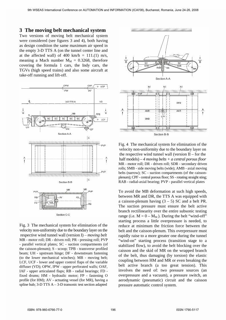
3 The moving belt mechanical systemTwo versions of moving belt mechanical systemwere considered (see figures 3 and 4), both havingas design condition the same maximum air speed inthe empty 3-D TTS A (on the tunnel center line andat the affected wall) of 400 km/h = 111.(1) m/s,meaning a Mach number MM = 0.3268, thereforecovering the formula 1 cars, the Indy cars, theTGVs (high speed trains) and also some aircraft attake-off running and lift-off.
Fig. 3 The mechanical system for elimination of thevelocity non-uniformity due to the boundary layer on therespective wind tunnel wall (version I) – moving beltMR - motor roll; DR - driven roll; PR - pressing roll; PVP- parallel vertical plates; SC - suction compartments (ofthe caisson-plenum); S - scoop; TPB - transverse profiledbeam; UH - upstream hinge; DF - downstream fastening(to the lower mechanical winches); MB - moving belt;LCF, UCF - lower and upper control flaps of the variablediffuser (VD); OPW, IPW - upper perforated walls; OAF,IAF - upper articulated flaps; RB - radial bearings; FD -fixed drums; HM - hydraulic motor; FP - fastening Oprofile (for HM); AV - actuating vessel (for MR), having aspline hub; 3-D TTS A – 3-D transonic test section adapted
Fig. 4 The mechanical system for elimination of thevelocity non-uniformity due to the boundary layer onthe respective wind tunnel wall (version II – for thehalf models) – 4 moving belts + a central porous floorMR - motor roll; DR - driven roll; SDR - secondary drivenrolls; SMB - side moving belts (wide); AMB - axial movingbelts (narrow); SC - suction compartments (of the caisson-plenum); CPF - central porous floor; SS - rotating straight sting;RAB - radial-axial bearing; PVP - parallel vertical plates
To avoid the MB deformation at such high speeds,between MR and DR, the TTS A was equipped witha caisson-plenum having (3 – 5) SC and a belt PR.The suction pressure must ensure the belt activebranch rectilinearity over the entire subsonic testingrange (i.e. M = 0 – MM ). During the belt “wind-off”starting process a little overpressure is needed, toreduce at minimum the friction force between thebelt and the caisson-plenum. This overpressure mustrapidly raise to a more greater one during the tunnel“wind-on” starting process (transition stage to astabilized flow), to avoid the belt blocking over thecaisson and the skid of MR on the wrapped branchof the belt, thus damaging (by torsion) the elasticcoupling between HM and MR or even breaking thebelt active branch (a too great tension). Thisinvolves the need of: two pressure sources (anoverpressure and a vacuum), a pressure switch, anaerodynamic (pneumatic) circuit and the caissonpressure automatic control system.
9th WSEAS International Conference on AUTOMATION and INFORMATION (ICAI'08), Bucharest, Romania, June 24-26, 2008
ISBN: 978-960-6766-77-0 196 ISSN 1790-5117

4 The model actuating in yaw system,position and loads measuring systemsTwo such systems (see figure 5), affecting either theTTS A ceiling or the DV upstream (model support),were considered. Both versions of the actuating systemmust allow the model rotation around a normal axisto the MB plane (active) branch in two modes:1. “step” - to measure the static pressure distributionon the model surface or also to visualize the flowspectrum in TTS A around the model (photo, video);2. “sweep” (continuously) - to measure the globalaerodynamic forces acting on the model (using a 6-component internal tensometric balance);always measuring the yaw angle and angular speed.
Fig. 5 Systems for actuating the given model inyaw motion (side-slip for the car models, or pitch -incidence for the aircraft half models – also see the
figure 4):a. the classical system (with a straight sting) – yaw;SWA - Schlieren window axis; PWA - photo window axis;B.C. - tensometric balance center; SS - rotating straightsting; PF - fixed profiled (biconvex symmetrical) fairing;RB - radial bearing; ARB - axial-radial bearing;
b. the new system (with a bent sting, worm gear andcylindrical worms actuated by d.c. electrical motorssolidary with the model) – yaw for car models, butalso pitch for aircraft models in take-off running andlift-off, and yaw combined with pitch for the (air)vehicle models with ground effect simulation;BS - fixed bent sting (with the vertical arm streamlined likePF); B.C. - fixed balance center; BSWG - balance sleeve -worm gear (a fixed assembly); CW - cylindrical worms; EM -d.c. electrical motors (synchronized), with a protectionsystem in the case of fall of some of them; RB - radialbearing; RAB - radial-axial bearing; US - upper shell; LS -lower shell; IW - intermediate wall; SGW - solar (central)gear wheel (solidary with BSWG); OE - optical encoder (forthe yaw angle); TG - tachogenerator (for the angular speed),each of them having a planetary (satellite) gear wheelsolidary on their shafts, geared with SGW, using an anti-backlash mechanics; the possible incidence angle of theaircraft models in take-off running and lift-off or of the(air) vehicle models with ground effect is measured by thewind tunnel existing OE (for the usual 3-D models testing)
Due to the bent sting, the system in figure 5b. has alesser value of the blockage ratio coefficient.Having a greater fixed part (BS - balance - BSWG -SGW assembly), it also has a lesser value for themoment of inertia around the rotation axis, allowinggreater values for the angular acceleration.Although more intricate, it has a greater mobilitythan that given in figure 5a, allowing yaw and pitch.But for these tests it needs two driving systems: theEMs and the strut (wind tunnel paralellogrammechanism of incidence).The central straight arrow indicates the flow sense.The + and – signs on the straight arrows indicate thesenses of displacement for the strut (S) and the stingsupport actuating arm (AA) to obtain the positive andnegative incidence of the sting support (see the + and –signs on the circular arc arrow).The active yaw motion is produced by five couplesacting on the model: a. the motor couple; b. thestatic aerodynamic couple - the same sense as a.; c.the damping aerodynamic couple - opposite to a.; d.the gyroscopic couple (taking into account themodel wheels and axles rotation, due to a separatesystem) - opposite to a.; e. the couple of thetangential forces of inertia - opposite to a. Asregards the senses of all these couples acting on thebalance, one can notice that the a. couple changes ofsense, being replaced by the couple of reactionforces given by the teeth flanks of the CWs (formodel driving in yaw) acting on the correspondingteeth flanks of the BSWG assembly, so that the b.couple equates the sum of the a. + (c. - e.) couples(the D’Alembert principle).
9th WSEAS International Conference on AUTOMATION and INFORMATION (ICAI'08), Bucharest, Romania, June 24-26, 2008
ISBN: 978-960-6766-77-0 197 ISSN 1790-5117

In figure 6 is given the action mode (scheme) of thestatic aerodynamic design loads torsor on a terrestrialvehicle model of formula 1, having a very efficientlystreamlined cab (the Jaray “wing-car” - see [4]).
Fig. 6 Design (critical for the balance) aerodynamicstatic loads on a terrestrial vehicle model - formula 1(Jaray “wing-car” - very efficiently streamlined cab)C.P. - center of pressure; C.P.1 � &�3� IRU � �L (givingthe 0 value for the X component); C.G. - center of gravity(reference point for the aerodynamic moments); W or D -aerodynamic drag; Y1 - aerodynamic force in the yaw plane,normal to W; T or X - axial force; S or Y - side force; L -aerodynamic lift; m - pitching moment; n - yawingmoment; l � UROOLQJ PRPHQW� 9 � DLU VSHHG� � � \DZ DQJOH�
The Jaray “wing-car” shape is well-known not onlyfor giving a minimum drag, but also for assuring agood side aerodynamic stability (in yaw) ([4]), thederivative with respect to the side-slip angle of theyaw moment aerodynamic coefficient about thecenter of gravity being strongly negative ([5]). Whileat the usual cars the T/W = X/D ratio is kept verynear to 1, on a range of side-slip angles from 0 to 35º(being practically insensitive from this viewpoint),the Jaray car has a special sensitivity, the respectiveratio being kept almost constant (at the value 1) untila side-slip angle of (20 – 25)º only, it decreasingUDSLGO\ DIWHU WKDW� UHDFKLQJ WKH YDOXH ���� DW � ��º�IRU D FRQILJXUDWLRQ� DQG WKH YDOXH ��� DW � ��º (foranother configuration). This phenomenon explanationconsists in the appearance of some axial (tangential)aerodynamic forces lesser and of some side (normal tocar symmetry plane) aerodynamic forces greater thanthe corresponding ones which appear in the evolutionwith moderate - great side-slip of an usual car (theJaray car in yaw is an airfoil with greater fineness).For design reasons we need of the balance equations:
7FRV � � 6VLQ � : �RU� ;FRV � � <VLQ � '�� (1)<FRV � ± ;VLQ � <1 ; (2)IRU � � �< ��� m = L·b = L·d ;IRU � �L (X = 0): n = Y·d1 (with d1 < d) ; and
l = L·b1 = L·d1 VLQ �L ;LI � � �L� ; ! �� LI � ! �L, X < 0 (X is changing the sign).
Dividing by D one obtains the non-dimensional form:
,�cosC
C1
�sin
1
C
C1;�sin
C
C�cos
C
C
D
X
D
Y
D
Y
D
X
−==+
CX/CD (= CT/CW� EHLQJ D IXQFWLRQ RI � JLYHQ LQ >�@�
)RU � �L and dividing by D, the equation (2) yields:
L
DY
LD
Y
D
YL
D
Y
�tan
CC
�sin
1
C
Cwith
C
C�cos
C
C1
1 =⇒==
D02
1D02YD0D C25.1�sinkCkCCC
1⋅≈+=+= ,
with CD0 § � DQG &L ± � � ERWK IRU � � �VHH >�@��
)RU �L § ��º : CD § ���� � &Y § � � &Y1 § ��� �To find the distances b = d and d1 between C.P. and&�*� IRU � � DQG � �L , see [4] and [7]. For amodel scale of 1:6 one gets d = 0.13 m; d1 = 0.11 m.To satisfy the Mach-Reynolds similarity a staticpressure ps = 6 bar is required. Corresponding to themaximum value for the Mach number, MM = 0.3268,a dynamic pressure qM = 0.43 bar and a total(stagnation) pressure p0M = 6.44 bar are obtained.
9th WSEAS International Conference on AUTOMATION and INFORMATION (ICAI'08), Bucharest, Romania, June 24-26, 2008
ISBN: 978-960-6766-77-0 198 ISSN 1790-5117

For a maximum value of the blockage ratio coefficientin the 3-D TTS A of 0.1, one obtains the maximumvalue of the model side area (this reference area AM
FRUUHVSRQGLQJ WR DQ \DZ DQJOH � ��º).)RU WKH ³QR \DZ´ FDVH �� ��� RU ZLWK PRGHUDWH \DZ�
the new reference area Am is deduced consideringthe model cross section like a square having aEORFNDJH UDWLR FRHIILFLHQW RI ������ �������
6 Secondary aerodynamic circuit forstarting the belt motion and the WTIn figure 7 is given the scheme of the aerodynamiccircuit necessary for starting the belt motion and thewind tunnel run, according to the end of chapter 3.
Fig. 7 The proposed scheme for the aerodynamiccircuits of trisonic blowdown wind tunnel adapted toterrestrial (road transportation) vehicle model testingAC1 - main aerodynamic circuit (of the blowdown windtunnel) – existent; AC2 - secondary aerodynamic circuit(pneumatic, parallel to AC1) – proposed; CC - commoncircuit (part) of AC1 and AC2 ; FST - final storage tank;EP - extension pipe; SOV1 - main shut-off butterfly valve;BPV1 - main by-pass butterfly valve; EJ - expansion joint;PRV1 - main pressure regulating valve; SC - settlingchamber; FN - flexible nozzle; 3-D TTS A – 3-D transonictest section adapted; PC - plenum chamber; VD - variablediffuser; ST - second throat (a VD section); VDE - variablediffuser extension; FD - fixed diffuser; CP - connectingpipe; TCP - telescopic connecting pipe; BST - bufferstorage tank; SOV2 - secondary shut-off butterfly valve;BPV2 - secondary by-pass butterfly valve; PRV2 -secondary pressure regulating valve; C – P - caisson-plenum; EV - electrovalve; BOV - blow-off butterfly valve
The new AC2 is similar and parallel to the main AC1,but has a much smaller mass flow rate. The circuitshave a CC, the BOV. This system ensures both therapid supply of C – P (at the “wind-off” MB startingand then at the run “wind-on” starting) with air at ahigh pressure nearest to that in the 3-D TTS A (toprevent the appearance of some huge friction forcesbetween MB and C – P with all the train of troubles)and the necessary suction from the C – P during thestabilized working of the installation, for keeping the
horizontal plane shape of the active branch surfaceof MB. The circuit contains an overpressure sourceand a vacuum one (the ST downstream, here being asupersonic flow for having a subsonic one in the 3-DTTS A), the pressure switch between these sourcesbeing an EV. It also contains a CP (or TCP). To ensurethe time correlation between the stabilized workingof the wind tunnel and that of the MB, an automaticcontrol system of the C – P pressure is necessary.
7 Other necessary systemsAmong these ones we cite: the hydraulic system forthe self-regulated tension of MB, to compensate thecomponent variable with rpm of the global elongationof the MB mean fibre (sheet); the hydraulic systemfor actuating in rotation of MR, including the needof power supply, to reduce the acceleration time fromequilibrium to the mean working velocities of the MBin the transitory regime of the motion priming; theposition, rpm, pressure and loads measuring systems.
8 ConclusionThe adaptation of the 3-D transonic test section of ablowdown type wind tunnel for correct ground effectsimulation tests is a laborious and pretentious task, butwhich, by the obtained advantages, justifies the efforts.
References:[1] Selescu, R.: Studiul privind adaptarea suflerieitrisonice la experimentarea vehiculelor de transportterestru. Tema de proiectare, I.M.F.D.Z. Report,code P-1088, Bucharest, 1992.[2] Dobre, A.: Adaptarea sufleriei trisonice pentruexperimentarea vehiculelor de transport terestru.Proiect sisteme mecanice (varianta I), I.M.F.D.Z.Project, code P-1237, Bucharest, 1993.[3] Selescu, R.: Completare tema de proiectaresistem mecanic covor rulant pentru adaptareasufleriei trisonice la experimentari autovehicule,I.M.F.D.Z. Report, code P-1419, Bucharest, 1994.[4] Hucho, W.-H.: Aerodynamik des Automobils,Vogel Verlag, Würzburg, 1981.[5] Schlichting, H.: Aerodynamische Untersuchungenan Kraftfahrzeugen, Institut für Strömungsmechanik,TU Braunschweig, 1953.[6] Migeot. J.-C.: Aérodynamique et Formule 1,article in “Eolia’86”, pp. 15 – 17.[7] Braess, H.-H., Burst, H., Hamm, L, Hannes, R.:Improvement of handling characteristics ofautomobiles by reducing the aerodynamic lift,article in “Proceedings Of The Second AIAASymposium On Aerodynamics Of Sports &Competition Automobiles”, AIAA, Los Angeles, 1974.
9th WSEAS International Conference on AUTOMATION and INFORMATION (ICAI'08), Bucharest, Romania, June 24-26, 2008
ISBN: 978-960-6766-77-0 199 ISSN 1790-5117