adaptive and controllable compliant systems with …btrease/share/trease-spie-2007.pdfadaptive and...
TRANSCRIPT

Adaptive and controllable compliant systems with embedded actuators and sensors
Brian Trease*, Sridhar Kota
The University of Michigan, Department of Mechanical Engineering, Ann Arbor, Michigan 48109
ABSTRACT
We present a framework for the design of a compliant system; i.e. the concurrent design of a compliant mechanism with embedded actuators and embedded sensors. Our methods simultaneously synthesize optimal structural topology and placement of actuators and sensors for maximum energy efficiency and adaptive performance, while satisfying various weight and performance constraints. The goal of this research is to lay an algorithmic framework for distributed actuation and sensing within a compliant active structure.
Key features of the methodology include (1) the simultaneous optimization of the location, orientation, and size of actuators concurrent with the compliant transmission topology and (2) the concepts of controllability and observability that arise from the consideration of control, and their implementation in compliant systems design. The methods used include genetic algorithms, graph searches for connectivity, and multiple load cases implemented with linear finite element analysis. Actuators, modeled as both force generators and structural compliant elements, are included as topology variables in the optimization. Results are provided for several studies, including: (1) concurrent actuator placement and topology design for a compliant amplifier and (2) a shape-morphing aircraft wing demonstration with three controlled output nodes. Central to this method is the concept of structural orthogonality, which refers to the unique system response for each actuator it contains. Finally, the results from the controllability problem are used to motivate and describe the analogous extension to observability for sensing.
Keywords: compliant mechanisms, genetic algorithm, optimization, embedded, actuator placement, distributed actuation, controllability
1. INTRODUCTION The basic premise of a compliant system is the integration of motion/force transmission via elastic deformation with embedded actuation and sensing. Current electromechanical systems are generally molded in the rigid-and-discrete paradigm where one first designs a rigid structure with mechanical joints and then adds actuators and sensors, with the design of controls only following as an afterthought. The goal of this research is to lay a mathematical framework for distributed actuation and sensing within a compliant active structure. In previous studies of compliant mechanisms (CMs) and their synthesis, single-actuator mechanisms have been considered, with the determination of the actuator’s type, orientation, size, and location occurring outside of the automated design synthesis, at the designer’s option. The objective of our research is a systems approach to synthesis of mechanism, actuator, and sensors, thereby advancing the path from traditional mechanical design to systematic compliant-mechatronic design. Our methods simultaneously synthesize structural topology and actuators placement for maximum energy efficiency and adaptive performance.
Figure 1 shows an example of the problem definition for actuator/sensor placement and a conceptual solution generated algorithmically based on our synthesis framework. This task is considered for multiple actuators in Example 1. A method for incorporating consideration of control during the design synthesis can enhance the controllability and responsiveness of an adaptive system. Central to this method is the concept of structural orthogonality, which refers to the unique system response for each actuator it contains, and is explored in Example 2.
1.1 Motivation
The motion-and-force-transmission part of the compliant system problem has been researched for more than a decade in the field of jointless monolithic devices called compliant mechanisms2-5 (CMs). These devices use flexure and deformation to transmit motion and force, rather than rigid bodies with conventional mechanical joints, providing several
*[email protected]; phone 734 763 4916; www.engin.umich.edu/labs/csdl/
Active and Passive Smart Structures and Integrated Systems 2007, edited by Yuji Matsuzaki, Mehdi Ahmadian, Donald Leo,Proc. of SPIE Vol. 6525, 65251R, (2007) · 0277-786X/07/$18 · doi: 10.1117/12.715919
Proc. of SPIE Vol. 6525 65251R-1

111111 11111 I
benefits such as elimination of mechanical joints, joint-wear, and joint-clearance. This design paradigm is inspired by nature, where strength and compliance are observed in its designs, as opposed to the goal of strength and stiffness employed in traditional engineering. In fact, we refer to such systems in terms of both mechanism and structure; in this paper, both conceptions are used. The interchangeability of these terms highlights the significance of the multiple roles played by this technology and blurs the distinction between a (flexible) structure and a (jointless) mechanism.
Figure 1: Vision of an adaptive compliant system. Beginning with a specified design space, external loading conditions, and desired
mechanical task, we seek to synthesize a fully-compliant system with embedded and distributed actuators and sensors.
This research extends the biological analogy to the creation of truly monolithic systems – autonomous, adaptive, efficient, self-contained devices. The design methods and the applications of CMs already apply to many domains in micro-, meso-, and macro-scales. The past success with CMs motivates a new level of sophistication in synthesis of compliant systems including controls and adaptive structures. Frecker1 illustrates the gaps in knowledge amongst these synergies. Her survey of the fields shows that work has been done in (1) actuator placement on non-compliant predetermined structures, (2) the actuator material distribution problem, and (3) the coupling structure for a prescribed actuator, which are incremental steps in the progression of adaptive structure technology. However, the topic of systems-level concurrent synthesis of actuator component placement and topology design, a fundamentally different approach to the design of smart mechatronic systems, has yet to be addressed. By combining these fields, a new paradigm emerges for comprehensive designs that offer a basis for autonomy via the improved energy efficiency and adaptability that the inherent compliance provides.
The concepts of controllability and observability (degree to which the external environment can be sensed) arise from the consideration of control – a natural question after the leap from single to multiple actuator structures. These concepts represent the structural adaptability of the system. The use of a compliant mechanism and structure then enables increased sensitivity and output function with fewer actuators/sensors. In other words, a reduced number of internalized sensors and actuators can effect and sense a large range of externalities over a large physical region.
The use of multifunctional elements as both structural members and actuators, the integration of multiple materials, and the freedom from dependency on external drives are specifically attractive to many fields. Many biomedical applications require these qualities, including surgical tools and grippers, active-assist joints, and active valves. At a larger scale, we can create sense-and-control response within compliant shape-morphing aircraft wings.
1.2 Background
Compliant mechanisms can be designed for any desired input-output force-displacement characteristics including specified volume/weight, stiffness, and natural frequency constraints. As flexure is permitted in these mechanisms, they can be readily integrated with unconventional actuation schemes including artificial muscle, thermal, electrostatic, piezoelectric, and shape-memory-alloy actuators. The synthesis of these mechanisms has been well studied2-5, and their advantages have been well documented, including: energy storage, ease of manufacture, and absence of wear, backlash, and friction. Synthesis typically involves two stages: (I) generation of the mechanism topology and (II) determination of optimum size, geometry, and shape of various constituent elements of the mechanism. Starting with functional requirements of desired forces and displacement, a conceptual design is automatically created in Stage I topology
design domain
external load
desired output
fixed
gro
und
Design Space / Problem Specification
external pressure sensing region
internal stress state sensors
actuators
flexiblestructure
outputforceFinal Design Conception
Proc. of SPIE Vol. 6525 65251R-2

synthesis. Based on material constraints (i.e. permissible stress, strain), fabrication constraints (e.g. minimum feature size), external loads, and desired mechanical advantage, the exact size, shape, and geometry of each beam element are optimized in Stage II.
1.2.1 Distributed compliance
A significant difference exists between the CMs discussed in this paper and conventional flexures. Conventional flexures have relatively rigid sections connected by very thin flexural joints. These flexures localize the deformation and are prone to high stresses and reduced fatigue life. Such flexures have been known for a long time6 (since 1965) and have been successfully employed in less-demanding applications (e.g. shampoo bottle lid). The mechanisms discussed here have distributed compliance, i.e. they deform as a whole and do not have any joints, flexural or conventional. The property of distributed compliance2 has enabled the study of compliant mechanisms for use in shape-morphing applications3,7-8 that are predecessors of this current work.
1.2.2 Controllability and observability
A collection of related literature regarding the optimal placement of actuators and sensors for acoustics and vibration control is summarized by Padula and Kincaid9. While many of these studies use genetic algorithms (sometimes simulated annealing), they focus on structure rather than mechanism (motion transmission) problems. Several researchers have investigated the placement of actuators on vibrating plates10,11 and at least one12 considers actuator and sensor placement on simple, fixed structures (1 to 3 beams), also for vibration suppression. Most authors examined only fixed topologies, except for the case of Begg and Liu, who did investigate simultaneous topology optimization and actuation placement for cantilevers13 and trusses14. Again, these are for vibration suppression in structures, not mechanical control of compliant systems. It remains to be seen whether the same metrics used for controllability and observability of smart structures for vibration suppression can be applied to compliant systems, which do not suppress vibration but perform prescribed mechanical tasks.
1.2.3 Actuator Architecture
There are a few literature references to the optimization of actuator architecture, which are similar in appearance to some aspects of the reported research. However, these methods are of different scope and employ different methods. Actuator architecture problems aim to lay out the material makeup of an actuator, but do not address how that actuator relates to the rest of a physical system. Most of these studies focus on the distribution of only the actuator material, without any supporting structural elements. (Silva: piezoelectric actuator material distribution15, and Anusonti-Inthra & Frecker: actuator material layout in a flexible airfoil16.) Their results show networks of only actuators. Such a structure may be suitable when considering the entire device as a single actuator component, but is impractical in describing implementation of discrete actuator components within a mechanical system. Bharti and Frecker17 consider the passive and active material distribution problem. However, the choice of actuator or structure is not a variable but a post-processing decision, and again, the results are not applicable to practical component layout.
1.2.4 Actuator placement
Bharti et al.18 and Johnson and Frecker19 have also investigated optimal multiple actuator placement. They employed different elements types than presented in this paper for their structure (i.e. trusses and tensegrity structures instead of beams) and determined active (piezoelectric) and passive material distribution within a structure by using genetic algorithms.
2. OVERVIEW OF METHODOLOGY The basic outline of the research is shown in a pictorial example (Fig. 2). First, the design specifications are identified, from which the problem type is determined (Fig. 2(a)). The available solutions to the problem potentially contain compliant mechanism, actuator, and sensor components. The design space must be properly parameterized in terms of these components (Fig. 2(b)), which is critical for the success of the optimization. The high-level goal of optimization in the embedded actuator problem is to minimize actuator number and size, to maximize energy efficiency, and to meet other constraints such as size, weight, displacement, and stress constraints. Application of a search method finds the optimal system (Fig. 2(c)). Results are further refined in size and shape optimization (Fig. 2(d)). Finally, there will be verification of the design and methodology via solid model finite element analysis and testing of functional prototypes (Fig. 2(e,f)).
Proc. of SPIE Vol. 6525 65251R-3

I I I I I I I I I
Design Space / Problem Specification
I I I I h I I
xDiscretized Ground Structure Result of Topology Optimization
externaldesired output
sensors
Size and Shape Optimization
sensors
ConpIient Systen design showr in thedeformed position
external pressure sensing
1<Z•nternaIstressstate sensors
2.1 Example 1 – multiple actuator placement
We report two examples of the methodology in use. The first is the traditional task of displacement amplification, accomplished with multiple actuators. The second task is a controllable shape-adaptive wing, possible only within the new multiple actuator formulation. Both problems use the same genetic algorithm (GA) for optimization and Grounded Structure Approach4,21 (GSA) for parameterization. The next section describes all the steps required for the first problem. The following section then discusses the second problem and the associated changes from the first method.
2.1.1 Parameterization by the discrete Grounded Structure Approach
In the code, the workspace is broken down into a grid of nodes, which are interconnected by beam elements (Fig. 3). A design variable exists for every element and determines whether the element exists. A value of Ø deactivates the element, removing it from the structure; other values represent three discrete thickness choices. In addition, there is a variable for every actuator to be used in the structure. This variable has a value between 1 and the total number of elements. Its value marks the element selected to be the actuator in a given structure. This approach guarantees a specified number of actuators for each problem and will prevent results like those seen in related literature. However, when using the GSA with a GA, a number of connectivity problems can occur; a variety of graph-checking constraints are added to resolve the issue.
(a) (b) (c)
(d)
(e) (f)
Figure 2: Various steps in the synthesis scheme. (a) design specifications (b) initial array of beam elements as a ground structure (c) optimized topology of beams, actuators, and sensors (d) size optimization
(e) deformed position (f) physical interpretation.
Proc. of SPIE Vol. 6525 65251R-4

co
C
C
C
C
C
C
C
<IFSdisplacement
0dispbccmcnt
(a) (b)
Figure 3: Design Domains and Discretization for Symmetric Amplifier Problem, 6x6 grid, 250 elements
2.1.2 Objective functions
A key aspect of the research is implementing the proper objective function to achieve meaningful results. The choice of objective function depends on the type of problem being solved, which is described as single-input-single-output (SISO), multiple-input-single-output (MISO), or multiple-input-multiple-output (MIMO, shape-change, adaptive, etc.) Most objectives include energy efficiency with regards to input work and output work. The maximization of energy efficiency leads to distributed compliance in our structures, and the new methodology allows for more complex constraints, motions, and shape changes. Other objective functions may be applied to minimize actuator power consumption, minimize the total number of actuators used, or to maximize the combined effect of multiple actuators. Shape-change objectives can be implemented via least squares formulations, by calculating the deviations of points on a deflected structure from corresponding points on a target curve. Additional objective function terms are available to maximize responsiveness and adaptability and to minimize total length of all elements present (much like a volume constraint). At this time, all objective function terms are calculated from the results of linear finite element analysis (FEA), with only one beam element placed between each of the nodes in the topology being analyzed. Finally, actuator segments serve as both force generators and structural elements.
In the first example, the objective function is to maximize energy efficiency, expressed in term of a spring-based efficiency, η. That is, while the actuators act against the structure at the input ports, springs (kout) are placed at the output ports to simulate the reaction loads (See Fig. 4).
Figure 4: (Left) Basis for calculation of Energy Efficiency. (Right) The Input and Output Work History (Spring formulation by Hetrick20)
This enables the easy calculation of work output (Wout) divided by work input (Win) in Eq. (1), where all forces and displacements are measured parallel to the intended direction of motion. Thus, this formulation does not include output work that does not contribute to the mechanism’s function. Hetrick20 provides a derivation for this formulation, shown in Fig. 4 (right).
actuator
dout
grou
nd
Fin1, din1
Fin2, din2
kout
kout dout
line
of
sym
met
ry
(b) output history
dout
kout
(a) inputhistory
din
Proc. of SPIE Vol. 6525 65251R-5

J\NSYS
-120 -100 -80 -60 -40 -20 0 20 40 60 80 100 1200
20
40
60
80
100
120
fixed ground
dout = 29.1mm compliant structure
output node
embedded actuator
2.1.3 Constraints
Of particular importance are constraints that guarantee the ground, input, and output are all connected to the same structure, and that there are no other floating structures. We have used connectivity constraints as a filter rather than an objective function term, by simply discarding and replacing the designs with connectivity violations. Other possible constraints include weight, peak-power consumption, and displacement requirements, of which we have implemented the last.
Two constraint penalties are added to the objective function to monitor deflection. The first is a constraint that requires the output deflection in the desired direction to be greater than a minimum value, dmin. The second requires the output deflection perpendicular to the desired direction be less than a maximum value, maxd⊥ . The final form of the objective function is shown in Eq. (2), where η is from Eq. (1) and w1 and w2 are relative weighting constants. In the formulation, the penalties are applied only when dout < dmin or ⊥
outd > maxd⊥ . (The tangential constraint is not needed for our symmetric example problem.)
%100
η
2
≤===∑∑ inin
outout
in
out
in
out
dFdk
WW
WW
(1)
[ ])d - (d )d- (d η maximize outmaxminout⊥⊥×+×+ 21 ww (2)
2.1.4 Discrete nonlinear topology optimization and synthesis
Given a model of the design space, the variables can be optimized via a genetic algorithm (GA) to yield a mechanism topology. GAs are a form of nonlinear optimization that seeks global optima as opposed to local optima and are especially suited for discrete, nonlinear problems. (See Eiben21 and Goldberg22 for more information.) Genetic algorithms convert the design variables into a long sequence of genes that can be propagated from generation to generation with the effects of cross-over and mutation. The best-fit individuals survive by scoring high against an objective (fitness) function.
Figure 5: Dual-Actuator Symmetric Motion Amplifier. dout = 29.1mm. din = ~0.5mm / actuator. Dashed lines represent deformed structure. Left: Matlab optimization results. Right: ANSYS nonlinear finite element analysis
The GA starts with a population of randomly generated designs. The selection scheme in GA is based on the “survival of the fittest.” In our work we also implement “genetic engineering”, i.e. the trimming of elements before fitness function and “Lamarckian trimming”, i.e. the trimming of elements after the fitness evaluation. The highest scoring members of the combined parent and offspring population become the parent population for the next generation, guaranteeing that good designs are not lost.
2.1.5 Results
Again, the task for this example is to amplify an input displacement into an output displacement along the device’s line of symmetry. Such devices have played an important role in the design of MEMS actuators23. The design specifications are actuator block force: 90N, element modulus: 2,480MPa, actuator modulus: 2,000MPa, output stiffness: 0.05N/mm,
embedded actuators
Proc. of SPIE Vol. 6525 65251R-6

and minimum output deflection: 20mm. Figure 5 shows results for the best of a population of 150 over 1,000 generations, with only one actuator variable.
2.1.6 Discussion
Encouraging results (Fig. 5) show that the algorithm attains the goal of distributed actuation and display the desired attribute of fully-distributed compliance. The symmetric amplifier problem is a benchmark in the field of compliant mechanisms4-5,20. The design depicted above is similar in topology to the more successful of previously reported high-gain results, such as MEMS amplifiers23, tailored actuator transmissions24, and results using a load-path method3. Note that we have focused only on topology optimization (Stage I), considered the more difficult of the two design stages. Further dimensional (size and shape) synthesis (Stage II) can be implemented with standard continuous optimization methods to address many other practical constraints and performance requirements.
2.2 Example 2 – design for controllability
The next line of research is the merger of compliant mechanism synthesis and “design for control” within the synthesis methodology for compliant systems. Our initial approach to integrate control with CMs is not to optimize the controller, but to optimize the controllability characteristics of the system, defined as measures of how thoroughly a given set of internal actuators/sensors can achieve/sense a full range of output states on the external environment.
Figure 6: Aircraft wing cross-section subject to unknown and arbitrary air load, f(x).
Points P1 and P2 are to be controlled by internal actuators and monitored by internal sensors.
(a) (b)
Figure 7: Design Space for the “Design for Control” synthesis problem.
Controllability and observability of the structure will be calculated in terms of the linear independence of the actuators and sensors, which will be incorporated into the optimization. The presented work on controllability provides the method for optimizing observability. We hypothesize that if the actuators independently affect the output displacement, then they can compensate for a variety of unknown loading conditions.
2.2.1 Problem formulation
As stated, the task of a compliant system is to serve as a mechanism with a specified functionality while also maintaining a structural stiffness to support external loads. We now look at adding adaptability to that definition, so that compliant
P1 P2
dy1 dx1
dy2 dx2
fixed
gro
und
external load, f(x)
P1 P2
actuator A actuator B
design domain
wing surface
air load, f(x)
P1 P2
Two output ports are indicated as well as two actuators. The location and orientation of the actuators are to be determined via synthesis. Actuation will result in deflections at P1 and P2. In this case, we are only concerned with the vertical (y) component of displacement.
Proc. of SPIE Vol. 6525 65251R-7

systems can detect and appropriately respond to unknown and arbitrary loading. Consider an example problem with an output region defined by two output points, P1 and P2. Imagine a simple airfoil that is to remain in a particular configuration despite changing pressure loads, as depicted in Fig. 6. These points will be subject to unknown loading in the vertical direction, f(x). Each point represents a degree of freedom of the system, and thus two actuators (A, B) are required (at a minimum) to fully control the output points.
2.2.1.1 Design space
The design space (Fig. 7) is nearly the same as that used in the basic embedded-actuation problem (see Fig. 6). A network of enumerated beams represents the underlying structure, with each beam being a design variable. The left-side of the design space is fixed to the ground. To guarantee a continuous airfoil, the top edge elements are not included in the optimization, but are pre-specified as known-thickness elements. For actuation, we use axial force actuators with specified stiffness (including bending) and output blocked force. The actual output load and deflection depend on the stiffness of the entire compliant system, and are determined by the FEA solution. The actuators are not binary (on or off) but continuously controlled, allowing for flexibility in mixing the independent effect of each actuator on the structure.
2.2.1.2 Loading
When calculating the fitness function within the synthesis procedure, the structures are first loaded by only the internal actuators, one at a time, with no external load. While the goal is to support external loads, those loads are not yet known. Instead, we attempt to optimize the actuator layout within the structure to result in the greatest freedom to control the displacement output points. Such a structure is believed to best handle variable load. The second example given in this section (Fig. 10) does consider external load, applied in an additional load case with no active actuators. The structural response in then added to the objective function in a minimization term.
2.2.2 Objective function and constraints
To develop a measure of controllability, the effect of each actuator within the structure is first tested via FEA. The output points P1 and P2 will have displacements (d1x, d1y) and (d2x, d2y). We are interested in the coupled output of both actuators in the vertical direction, represented by the vector: iyyi ddd ],[ 21= , where “i” represents the active actuator.
Thus, for actuator A, AyyA ddd ],[ 21= . Likewise, a second FEA is run with actuator B activated, resulting in:
ByyB ddd ],[ 21= .
2.2.2.1 Linear independence
To increase the controllability of the structure, it is desired that the id vectors be linearly independent. This condition means that the effect of each actuator will not be redundant, allowing for the controller to be effective. Thus, the combination of the two actuators ( BBAAcombined dwdwd += ) can be used to cover as broad a range of output combinations as possible. An example of potentially orthogonal vectors is shown in Fig. 8. By the nature of compliant structures, all output points are affected by all actuators, making it impossible to have each output point simply controlled by only one input. That is, a scenario such as ]0,1[=Ad and ]1,0[=Bd is not possible, but other linearly
independent combinations should be achievable, such as ]5.0,5.0[=Ad and ]5.0,5.0[ −=Bd .
2.2.2.2 Controllability
We define controllability as the degree of independence between the two vectors, evaluated as a number ranging between zero and one, obtained by creating a matrix of the id vectors and then dividing its determinant by the product of the magnitudes of the vectors, as shown in the formula below:
mBA
mBAc
dddddd
L
L ]det[=η (3)
(where m is the number of outpoint points, equal to the number of actuators)
Proc. of SPIE Vol. 6525 65251R-8

Here, a value of zero implies linear dependence, while values closer to one imply orthogonality of the m vectors. The controllability, ηc, serves as the objective function to be maximized during the genetic algorithm. (Note: orthogonality is a rather basic and limited estimation of linear independence. In our continuing work, we are implementing more common measures based on the Jacobian of the transformation, such as condition number and the ratio of singular values.)
Figure 8: An example of two possibly orthogonal actuation modes. It is seen how the deformations due to each actuator are not only
different, but also not redundant.
2.2.2.3 Other constraints and terms to be optimized
While the primary objective is the orthogonality of the output vectors, it is also required that these vectors surpass a minimum displacement magnitude so that the structure can sufficiently deform. This can be checked by making sure that for every output point at least one vector meets the minimum displacement required of that point. The volume is also minimized in each of the following designs, while the second example also minimizes deflection under an external load applied at the output nodes opposite the desired direction of motion.
2.2.3 Results
Again, the task for these examples is to control a simple airfoil exposed to unknown and variable pressure loads along its external surface. The design specifications are actuator block force: 90N, element modulus: 2,480MPa, and minimum output deflection: 5mm. Each problem used the same design domain, similar to that in Fig. 7, but with three output nodes.
Figure 9 shows results for the best of a population of 200 over 680 generations. Note the orthogonality of the output curves; the shapes are more complex than any trivial solution (where each actuator primarily affects only one output node): all of the nodes are moving, yet high orthogonality (99.98%) is still achieved. However, the first and last skin nodes are cantilevered and have questionable integrity if under external loads, leading us to the second example with the additional external load case present. Figure 10 shows the results for the best of a population of 200 over 1,500 generations, with an additional load case to establish structural integrity. High orthogonality is achieved (99.99%) and the maximum vertical deflection for a downward load of 10mN simultaneously applied at all three output nodes is 0.022mm.
fixed
gro
und
P1
P2
actuator A actuator B ON
d1y,B
d2y,B
fixed
gro
und
P1 P2
actuator A ON
actuator B
d1y,A d2y,A
Proc. of SPIE Vol. 6525 65251R-9
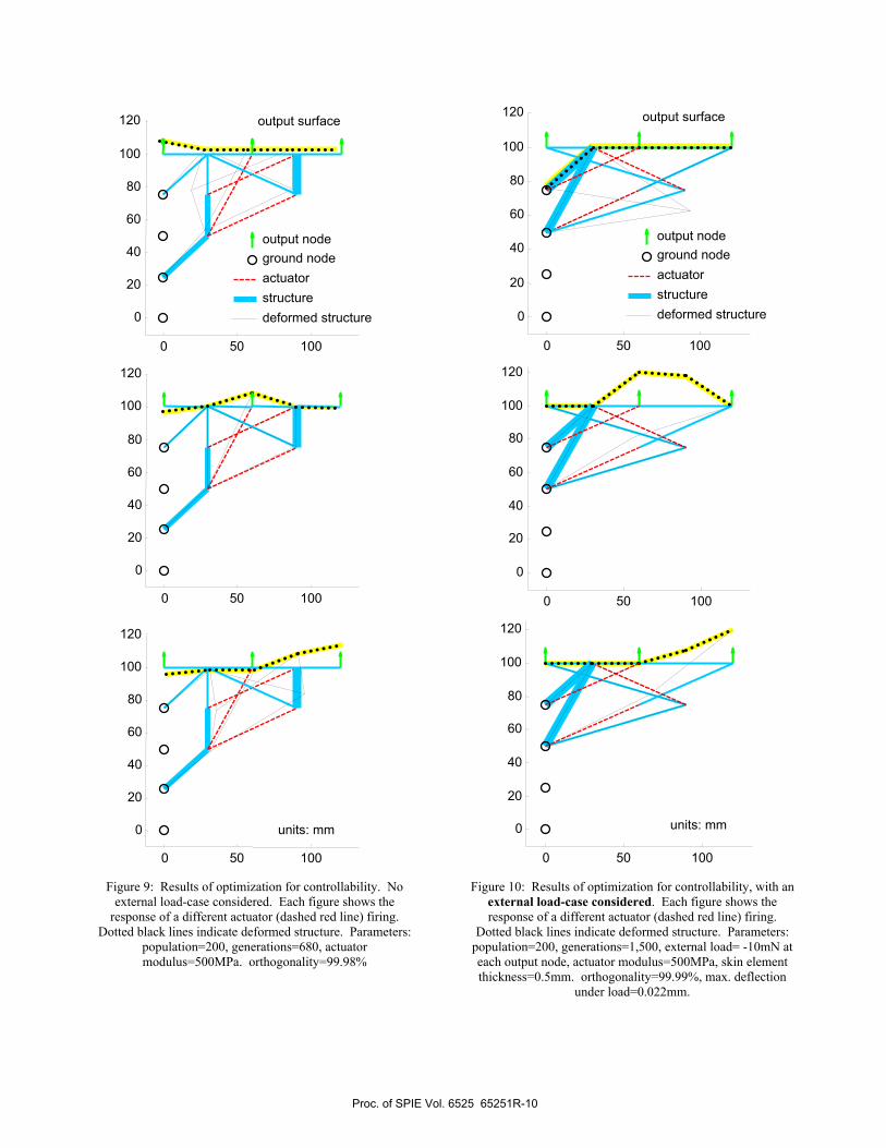
Figure 9: Results of optimization for controllability. No
external load-case considered. Each figure shows the response of a different actuator (dashed red line) firing.
Dotted black lines indicate deformed structure. Parameters: population=200, generations=680, actuator modulus=500MPa. orthogonality=99.98%
Figure 10: Results of optimization for controllability, with an external load-case considered. Each figure shows the response of a different actuator (dashed red line) firing.
Dotted black lines indicate deformed structure. Parameters: population=200, generations=1,500, external load= -10mN at each output node, actuator modulus=500MPa, skin element thickness=0.5mm. orthogonality=99.99%, max. deflection
under load=0.022mm.
0 50 100
0
20
40
60
80
100
120
0 50 100
0
20
40
60
80
100
120
0 50 100
0
20
40
60
80
100
120
ground nodeactuator structure deformed structure
output node
output surface
units: mm
0 50 100
0
20
40
60
80
100
120
0 50 100
0
20
40
60
80
100
120
0 50 100
0
20
40
60
80
100
120
ground node actuator structure deformed structure
output node
output surface
units: mm
Proc. of SPIE Vol. 6525 65251R-10

2.2.4 Discussion
We are very encouraged that the results are not trivial designs, i.e. actuators merely connected directly from the output nodes to the ground (or to floating nodes effectively grounded by stiff connections to the ground). Over the course of many (20+) runs, it was also observed that values for orthogonality tend to be below 10% or greater than 90%, for all structures, both random and optimized. This discontinuity, not yet fully understood, makes it difficult for the optimizer to balance the requirements for orthogonality and large displacements. Typically, one or the other dominates the objective function and the other falls far behind. Many parameters have been identified which might make this balance more even; some have been implemented in the second example. The balance is very sensitive to the values for skin modulus, actuation modulus, skin grounding, and the presence of an output load; these all not only affect the design, but specifically affect the displacement/orthogonality conflict. Connection of the skin elements directly to the ground constrains both the deflection magnitude and the flexibility required for controllability. Skin elements that are too compliant or actuator elements that are too stiff make orthogonality overly easy to achieve, resulting in its dominance. In effect, these conditions decrease the coupling between the three output nodes. Manipulating all of these initial parameters, in the presence of the volume constraint, has made for the design seen in Fig. 11. Only one actuator response is shown, and while it may appear an inelegant mess, analysis has shown that every element is critical to the four functions this device is achieving: orthogonality of three actuator responses at 99.88% and deflection under load of only 0.86mm. In fact, the device maintained the large number of elements even after a run of 1,500 generations under pressure for minimal volume.
0 50 100
0
20
40
60
80
100
Figure 11: Finding the balance between orthogonality and deflection. (Responses shown for 2 of the 3 actuators.)
Parameters: population=200, generations=1,500, external load = -1N at each output node, actuator modulus=1,000MPa, skin element thickness=1mm. orthogonality=99.88%, max. deflection under load=0.86mm.
3. EXTENSION OF METHODOLOGY TO EMBEDDED SENSING Sensors are also required in any controlled system. In this section we will develop a means for measuring observability that is very analogous to the method already given for measuring controllability. Through an inversion of inputs and outputs, the framework for embedded actuation can next be extended to distributed sensing. While these are analogous, some new issues are sure to arise and will be the subject of near future research. Of key significance is that this is not the traditional ad hoc design; sensor design will be simultaneous and synergistic, with sensor placement affecting structural topology and vice versa. This new sensing paradigm corresponds to an “internal state of stress” that relates to the external conditions of the system environment.
3.1 Formulation
The goal is now to describe the conditions at the output points described in the previous section, P1 and P2. It may be desired to know the pressure load acting on those points or the shape of the deformed curve. We consider these
0 50 100
0
20
40
60
80
100 units: mm
crossing beams areoverlapping, not
connected
Proc. of SPIE Vol. 6525 65251R-11

equivalents as they are related by the structural elasticity. In this example, we will look at the ability of the sensors to detect pressure loadings of unknown shape.
Figure 12: Response of “embedded and distributed sensors” to different applied loads. The loadings are designed to be orthogonal,
with the intent that the actuators respond differently and uniquely to each loading case.
The integration of sensor and structure is slightly different now, as there will be no “beam replacement” as there was for the actuators. Rather, the nature of the embedded sensors allows them to be directly added to the beams, without changing the beam properties. Two sensing strategies are identified as applicable: strain gauges placed directly on the beams or embedded mutual inductance sensing (MIS, see Peshkin U.S. Patent25).
The task of optimal distributed sensing is to find beam deflections that correspond to orthogonal external loading. For example, we consider two orthogonal loads by loading only one output point at a time (Fig. 12). Just as two FEA runs were required before for finding the output vectors for each actuator ( Ad and Bd ), two FEA runs are required to find the sensing vector for each loading condition ( Is and IIs ). The sensing vector comprises the total signal (ε) found in each of the embedded sensor beams: iis ],[ 21 εε= , and observability is defined as:
mIII
mIIIo sss
sssL
L ]det[=η (4)
4. DISCUSSION Considering the low fidelity of the modeling, the attainment of results that display all of our design requirements is very promising. The addition of nonlinear analysis and additional analysis elements for each beam will allow greater flexibility in any given structure and increase the likelihood of more and better multi-functional solutions. These studies also pointed out other basic research issues, particularly in parameterization and forming objective functions. Convergence required complex, nonstandard “genetic engineering” of our design population members during the GA: trimming of superfluous substructures, computationally expensive graph searches, and identification of ineffective rigid-body segments. The unbalanced tradeoff between controllability and large deflection has also been identified, along with a family of parameters to balance the struggle. Finally, the GSA works as a benchmark, but its complexity motivates exploration of other approaches, such as the Load-Path Method described by Lu3,8.
5. FUTURE RESEARCH Further work may enable new applications in the compliant paradigm, such as medical implants (low back pain/disk replacement), exoskeletons, adaptive-fit prosthetics, artificial organs, flapping-wing micro-air-vehicles, and reconfigurable surfaces for a wide range of applications. Variable stiffness of CMs is an interesting open research question that can be tackled by dividing our actuators into “function” groups and “adjustment” groups. Specific methods to explore include alternate parameterization, such as Load Path (connectivity-based discretization), and nonlinear FEA analysis within synthesis. The imminent extension from controllability to observability will be followed by the
P1 P2
embedded sensor 1
embedded sensor 2
Loading II
ε2,II
ε1,II
fixed
gro
und
P1 P2
embedded sensor 1
embedded sensor 2
Loading I
ε1,I
ε2,I
Proc. of SPIE Vol. 6525 65251R-12
combination of both terms within the same objective function. A future example is a wing that can change between different trailing edge configurations and be adaptable to various loading conditions while in either configuration.
REFERENCES
1. Frecker, M., “Recent Advances in Optimization of Smart Structures and Actuators,” Journal of Intelligent Material Systems and Structures, 14(4-5), pp. 207-216, 2003 2. Yin, L. and Ananthasuresh, G.K., “Design of Distributed Compliant Mechanisms,” Mechanics of Structures and Machines, 31(2), pp. 151-179, 2003 3. Lu, K.J. and Kota, S., “Design of Compliant Mechanisms for Morphing Structural Shapes,” Journal of Intelligent Material Systems and Structures, 14(6), pp. 379-391, 2003 4. Frecker, M.I., Ananthasuresh, G.K., Nishiwaki, S., Kikuchi, N., and Kota, S., “Topological Synthesis of Compliant Mechanisms Using Multi-Criteria Optimization,” ASME Journal of Mechanical Design, 119(2), pp. 238-245, 1997 5. Saxena, A. and Ananthasuresh, G.K., “Topology Optimization of Compliant Mechanisms with Strength Considertations,” Mechanics of Structures and Machines, 29(2), pp. 199-221, 2001 6. Paros, J.M. and Weisbord, L., “How to Design Flexure Hinges,” Machine Design, pp. 151-156, 1965 7. Saggere, L. and Kota S., “Static Shape Control of Smart Structures Using Compliant Mechanisms,” AIAA Journal, 37(5), pp.572-578, 1999 8. Lu, K., “Synthesis of Shape Morphing Compliant Mechanisms”, Ph.D. thesis, The University of Michigan, Ann Arbor, MI, 2004 9. Padula, S. and Kincaid, R., “Optimization Strategies for Sensor and Actuator Placement,” NASA Technical Memorandom/TM-1999-209126, 1999 10. Hać, A. and Liu, L., “Sensor And Actuator Location In Motion Control Of Flexible Structures,” Journal of Sound and Vibration, 167(2), pp. 239-261, 1993 11. Sadri, A.M., Wright, J.R., and Wynne, R.J., “Modelling and optimal placement of piezoelectric actuators in isotropic plates using genetic algorithms,” Smart Mater. Struct., 8, pp. 490-498, 1999 12. Bruant, I., Coffignal, G., Lene, F., and Verge, M., “A Methodology for Determination of Piezoelectric Actuator and Sensor Location on Beam Structures,” Journal of Sound and Vibration,” 243(5), pp. 861-882, 2001 13. Liu, X., Begg, D.W., and Matravers, D.R., “Optimal Topology/Actuator Placement Design of Structures Using SA,” J. Aerosp. Engrg., 10(3), pp. 119-125, 1997 14. Begg, D.W. and Liu, X., “On simultaneous optimization of smart structures - Part II: Algorithms and examples,” Computer Methods in Applied Mechanics and Engineering, 184(1), pp. 25-37, 2000 15. Nelli Silva, E.C., Nishiwaki, S. and Kikuchi, N., ‘‘Topology Optimization Design of Flextensional Actuators,’’ IEEE Transactions and Ultrasonics Ferroelectrics, and Frequency Control, 47(3), pp. 657–671, 2000 16. Anusonti-Inthra, P., Gandhi, F., and Frecker, M., “Design of a Conformable Rotor Airfoil Using Distributed Piezoelectric Actuation,” Proceedings ASME Int. Mechanical Engineering Congress and Exposition, Adaptive Structures Symposium, Washington, DC, IMECE2003-42659, 2003 17. Bharti, S. and Frecker, M., “Compliant Mechanical Amplifier Design Using Multiple Optimally Placed Actuators,” Proceedings ASME Int. Mechanical Engineering Congress and Exposition, Adaptive Structures Symposium, Washington, DC, IMECE2003-42658, 2003 18. Bharti,S., Frecker,M., Lesieutre,G., and Ramrakhyani,D., “Optimal design of tendon-actuated morphing structures: nonlinear analysis and parallel algorithm,” Proc. SPIE Smart Structures and Materials, 5757, pp. 132-143, 2005 19. Johnson, T. and Frecker, M., “Optimal Placement of Active Material Actuators Using Genetic Algorithm,” Proc. of SPIE, Smart Structures and Materials, 5383(1), pp. 221-231, 2004 20. Hetrick, J. and Kota, S., “An Energy Formulation for Parametric Size and Shape Optimization of Compliant Mechanisms,” ASME Journal of Mechanical Design, 121, pp. 229-234, 1999 21. Eiben, A. and Smith, J., Introduction to Evolutionary Computing, Springer, New York, NY, 2003 22. Goldberg, D.E., Genetic Algorithm in Search, Optimization, and Machine Learning, Addison Wesley, Reading, MA, 1989 23. Kota S., Hetrick, J., Rodgers, S., and Li, Z., “Compliant Displacement Amplification Apparatus for Micro Electro Mechanical Systems,” U.S. Patent No. 6,175,170, 2001 24. Kota, S., Hetrick, J., Li, Z., and Saggere, L., "Tailoring Unconventional Actuators Using Compliant Transmissions: Design Methods and Applications," IEEE/ASME Transactions on Mechatronics, 4(4), pp. 396-408, 1999 25. Peshkin, M., “Force Sensors,” U.S. Patent No. 20,040,261,544, 2004
Proc. of SPIE Vol. 6525 65251R-13