adaptive boolean logic using ferroelectrics capacitors as...
TRANSCRIPT

0
Adaptive Boolean Logic Using FerroelectricsCapacitors as Basic Units of Artificial Neurons
Alan P. O. da Silva1, Cicília R. M. Leite2, Ana M. G. Guerreiro3, Carlos A. Pazde Araujo4 and Larry McMillan5
1,3Federal University of Rio Grande do Norte2 State University of Rio Grande do Norte And College of Science and Technology Mater
Christi4,5Symetrix Corporation
1,2,3Brazil4,5USA
1. Introduction
Neural networks are being investigated as a computational paradigm in many fields ofartificial intelligence.The pioneers of cybernetics were clearly inspired by neurology and the current knowledgeof the human brain to develop the architectures of modern computing machines. Theevolution has given the brain very distinctive capabilities of learning, distributed memory,computation, generalization, robustness, and the capability of interpretation of imprecise andnoisy information, etc., not present in Von Neumann computers.Neuroengineers have come up with the idea of using Artificial Neural Networks (ANNs)massively parallel computing machines inspired by the biological nervous systems. However,ANNs have a very different approach and computing paradigm, where learning fromexamples and learning from iteration replaces our common idea of programming. Thesemodels achieve good performance via massively parallel networks composed of generallynonlinear computational elements, referred to artificial neurons. Synaptic weights areassociated with each neuron connection between neurons. In the case of classical ANNs, theactivation potential and the synaptic weights are analogous, respectively, to the firing ratesand the strength of the synapse in biological neurons which are arranged in layers.The first, very simplified model, mathematical model of a neuron operating in an all-or-nonefashion: the Threshold Logic Gate (TLG). It did not take very long for a hardwareimplementation to be developed. Since then a lot of researh have been developed with the aimof implementing artificial neurons in hardware and construct intelligent systems On-Chip.Many theoretical results have been shown that threshold logic circuits are more powerfuland/or efficient than Boolean circuits (Beiu et al., 2006). Exploiting the principle for electronicscircuits may reduce the number of transistors and interconnections (Shibata and Ohmi, 1991).Output-wired threshold gates working in the classical above threshold domain have beenimplemented, too. A lot of work has been done in this area. Thinking on this scenario, thischapter shows a implementation of the boolean logic with artificial neuron type model with a
11
www.intechopen.com

2 Will-be-set-by-IN-TECH
Ferroelectric (Fe) capacitor as its basic unit. The Fe Capacitors was chosen because it have beenembedded into LSIs as Ferroelectric Random Access Memory (FeRAM) and their reliabilitydata have been accumulated. The capacitors are high impedance device, and it is an advantagefor low power consumption, besides the configuration can be changed after packaging. TheFeCapacitor uses the phenomenon of the hysteresis loop as the activation function for theneuron model. The model performs a weighted sum of the inputs and applies it the non-linearactivation function generated by a single side of the hysteresis. Changing the weights, it ispossible to reconfigure the gate easily. Ones tries to show a new way of implementing aneuron, without using transistors.We developed the perceptron model with the FeCapacitor, that we called here FePerceptron,and we also developed the FeSpiking Neuron model, that is an extended model for thespiking neuron (Guerreiro et al., 2008) using the FeCapacitor as its basic unit for the activationfunction. Both models is going to be simulated and tested in Matlab. The models were used tosimulated all logical gates and synthesis of several digital circuits as D-flip-flop, shif-register,full adders, and a simple CPU with the Spiking FeNeuron. The Spiking FeNeuron isdeveloped because it can simulated all logical gates, inclusive the XOR gate with singleneuron, which is impossible with a single Perceptron.Because of the simplicity, we started the hardware implementation with the FePerceptron inan Field Programmable Gate Arrays (FPGA). The FeCapacitor is developed as its basic unitand can be used in any neuron model as activation function. We used the DSP builder ofAltera to generate the model. The DSP Builder Signal Compiler block reads Simulink ModelFiles developed (.mdl) that are built using DSP Builder blocks and generates the VHDL files.This is the first step of a work to implement in hardware the neuron using FPGAs simulatingthe desired hardware, bringing a second degree of reconfigurability to the FPGAs with theadaptive boolean logic CPU.This chapter is organized as follow, first in section 2 we give an overview of several developedworks and researches that were done simulating and implementing neural networks inhardware. Section 3 shows the development of the mathematical model of the FeCapacitor.The FeCapacitor model is used as activation function to the Perceptron model generating theFePerceptron and to the Extended Spiking Neuron model generating the FeSpiking NeuronModel as shown in section 4. The simulations in Matlab of both models are shown in section5 with the realization of boolean logic gates and adaptive boolean circuits. The section 6 isresponsible to shown the FePerceptron model developed in an FPGA. Finally, conclusion arepresented in section 7.
2. History of neuron models, simulations and implementation of neural networks
in hardware
The hardware implementations means and introduces for example computational errors,degradation of learning and lack of accuracy in results. This are some issues that have beenstudied and address and explored in many researches. These include digital (Bermak andMartinez, 2003; Kung, 1992; Lenne, 1995), analog (Brown et al., 2004; Mead, 1989), hybrid(Lehman et al., 1996; Schmid et al., 2004), FPGA based (Nedjah and Mourelle, 2007; Raket al., 2009; Schrauwen and D’Haene, 2005), and (non-electronic) optical implementations(Moerland, 2007; Tokes et al., 2000).In spite of all the difficults to implement ANN in hardware a lot of research have been done.There is a lot of needs in real-world applications. Some examples are: optical characterrecognition, robotics, voice recognition, adaptive filters, image analysis, finger print feature
232 Ferroelectrics - Applications
www.intechopen.com

Adaptive Boolean Logic Using Ferroelectrics Capacitors as Basic Units of Artificial Neurons 3
extration, acoustic sound recognition, olfactory sensing, traffic monitoring, experiments inhigh energy physics (Lamela and Ruiz-Llata, 2005), and adaptive control.There are indeed several surveys which have appeared in the past. There is this one (Janardanand Indranil, 2010) that has done a survey which includes most of all works concerningHardware Neural Networks (HNN). Here, we only give a small overview over what wasdone in the past based on (Janardan and Indranil, 2010), so the importance of the HNNcan be noticed, and seen that a lot of research has already been developed. Some earlyreferences on the VLSI implementations can be found on (Mead, 1989) and (Glesner andPoechmueller, 1994). An overview on neurocomputers up to the 90’s, built from accelatorsboards, general purpose hardware, and neurochips can be found on (Heemskerk, 1995).Digital implementations with custom processors can be found (Ienne, 1996).Sundararajan and Saratchandran (1998) discuss in detail various parallel implementationaspects of several ANN models using various hardware architectures. Zhu and Sutton(2005) survey FPGA based implementations of ANNs discussing different implementationtechniques and design issues. Smith also discuss and survey digital and analog VLSIimplementations approaches in neural model.One of the latest surveys with specific focus to commercially available hardware can befound on Dias et al. (2004). Neurofuzzy hardware systems is discussed concerning aspectsof various tecnologies of hardware implementations and software co-design techniques.Implementations of Spiking Neural Networks is provided by (Schrauwen and D’Haene, 2005).Valle (2005) presents various approaches to built smart adaptive devices.There still some topics as hardware friendly learning algorithms, as pertubation learning(Jabri and Flower, 1991), constructive learning (Smieja, 1993), cascade error projection learning(Duong, 1995; Duong and Stubberud, 1995), and local learning (Chen et al., 2000). SomeHNN based on Multilayer Perceptron (MLP) (D’Acierno, 2000; Kumar et al., 1994), radialbasis function (Fakhraie et al., 1994; Verleysen et al., 1994; Yang and Paindavoine, 2005), andNeocognition (Patnaik and Rao, 2000) and neurocomputers(Glesner and Poechmueller, 1994;Strey and Avellana, 2000).
3. The mathematical model of ferroelectrics capacitor
There are two areas of research to be investigate, the physically based models and thebehavioral models. In our work, the bahavioral modeling was chosen because it does notrequired a detailed knowledge of ferroelectric theory; it only requires a careful observation ofthe ferroelectric capacitor behavior from the circuit point of view.A lot of research have been done in attempts to models the behavior of a ferroelectriccapacitors (for a review, see: (Sheikholeslami and Gulak, 1997) since they were introducedas storage elements in integrated nonvolatile memory applications.In this paper, the Mathematical Model (Miller et al., 1991) is used that introduces a closed formmathematical equation for the hysteresis loop.Based on the saturability of the switching polarization and the symmetry of the hysteresisloop, the mathematical model approximates the saturated polarization loop with twohyperbolic functions:
P+sat(E) = Pstanh[
E − Ec
2δ] (1)
and,
233Adaptive Boolean Logic Using Ferroelectrics Capacitors as Basic Units of Artificial Neurons
www.intechopen.com

4 Will-be-set-by-IN-TECH
P−sat(E) = −P+
sat(−E) (2)
where P+sat(E) and P−
sat(E) represent the polarization corresponding to the positive andnegative going branches of the hysteresis loop, respectively. Ps and Ec are the saturationpolarization and the coercive field extracted from an actual hysteresis loop. With the fixedPs and Ec, δ is uniquely specified by Pr, the remanent polarization, through the followingequation:
δ = Ec[ln(1+ Pr/Ps
1 − Pr/Ps)]−1 (3)
A sketch of the hysteresis loop is done with MATLAB as it is shown in Figure 1. The symmetrywith respect to the origin in this Figure is guaranteed by Equation (2).
Pr
-Pr
Ps
-Ps
Ec
Fig. 1. The hyperbolic tangent functions approximate the Saturated Polarization Loop. Thehysteresis loop is plotted considering the values of Ps = 23 μ C/cm2, Pr = 15μ C/cm2, and Ec
= 40kV/cm2 borrowed from an actual saturated hysteresis loop.
The Mathematical Model provides a good approach for steady-state analysis of ferroelectriccapacitor behavior, and this model is sufficient by now for this work. Future simulationsmaybe can incorporate the transient analysis and by than mode accurate models can benecessary.
4. The ferroelectrics capacitor as an activation function of artificial neurons
4.1 Perceptron model
The biological neuron is the structure unit of the nervous systems. It considers of a cell body,called soma, axon and several ramifications. These ramifications are called, dendrites. Thedendrites conduct action potentials or electrical pulses toward the body cell and conform inlarge and complicated trees. The dendrites and the soma constitute the input surface of theneuron. The axon consists of a large fiber whose branches form the axonal tree. The axon hasa arborization at its terminal. The tips of the branches of the axon are called nerve terminals,boutons or synaptic knobs. The axon acts as a transmission line. The action potential travelsalong an axonal tree all the way to the nerve terminals. The terminals of the branches makecontacts with the dendrites of other neurons. The contacts are called synapses.
234 Ferroelectrics - Applications
www.intechopen.com

Adaptive Boolean Logic Using Ferroelectrics Capacitors as Basic Units of Artificial Neurons 5
The first computational model of the biological neuron was introduced by McCulloch andPitts (McCulloch and Pitts, 1943) in the 1940s. McCulloch and Pitts merged mathematicallogic and neurophysiology to propose a binary threshold unit as a computational model foran artificial neuron operating in discrete time. The output yk(t) of a neuron is 1 when an actionpotential is generated, and −1 otherwise. A neuron fires when the effects of inhibitions andexcitations are larger than a certain threshold, θ.In 1958, the American psychologist Rosenblatt proposed a computational model of neuronsthat he called The Perceptron (Rosemblatt, 1958). The essential innovation was the introductionof numerical interconnection weights.A neuron is an information processing unit that is fundamental to the operation of a neuralnetwork (Haykin, 1998). The perceptron model of the neuron has three basic elements (Figure2):
1. Synapses that are characterized by the strength of the weights;
2. An adder for summing the input signals, weighted by the respective synapses and thethreshold of the neuron;
3. An activation function for limiting the amplitude of the output (in this case completelyunclocked with the firing event).
Fig. 2. Perceptron Model
The external threshold, denoted by θ, has the effect of increasing or lowering the net input ofthe activation function, depending on whether it is positive or negative.The perceptron consists of a linear combiner followed by a non-linear function, as depictedin Figure 2. The summing node of the neuronal model computes a linear combination ofthe inputs, xi, applied to the synapses connections, wi, and also incorporates an externalthreshold, θ. The resulting sum, that is, the induced local field, is applied the activationfunction. The activation function denoted by Φ(υ), defines the output of the neuron in termsof the local field, υ. The activation function usually used is a sigmoid. The weights model thesynaptic strength, and the output of the neuron models the rate of fire of biological neurons.The threshold can be accounted for in two ways: adding a new input signal fixed at +1 oradding the threshold to the linear combination of the input with the weights.The neuron can be described mathematically as:
υ =p
∑j=1
ωjxj (4)
235Adaptive Boolean Logic Using Ferroelectrics Capacitors as Basic Units of Artificial Neurons
www.intechopen.com

6 Will-be-set-by-IN-TECH
andy = φ(υ + ω0θ) (5)
The capacity of learning is one of the most important characteristics of an ANN. Learningis closely related to an improvement of performance of the system. This is achieved byminimizing errors, self-organizing information through correlations of data, and maximizingrewards in a trial-and-error system over time. In practice, learning is achieved by adjustmentof the free parameters of the ANN.
4.1.1 The FePerceptron model
Our simplified model is based on the perceptron model, using the following concepts: inputs,synapses strength, adder, activation function and the threshold.The FeNeuron uses the ferroelectric capacitor as its basic unit. The model (Figure 3) iscomposed by the input, xi, by the synaptic weights, wi, as resistors, combining them linearly.The result is applied to the ferroelectric capacitor performing the output of the model. Thephenomenon of the hysteresis loop is used to act as the activation function. It is necessary touse only one side of the hysteresis loop.
Fig. 3. The FeNeuron Model
The induced local field of the neuron is computed as in Equation (4). The output is describedas:
y = P+sat(υ + ω0θ) (6)
and,
P+sat = P+
sat/Ps (7)
The Equation (6) can be re-written as:
y = P+sat(
p
∑j=1
ωjxj + θ) (8)
The goal of the model in this case is to classify correctly the set of externally applied stimuli,x1, x2, x3, ..., xp into two classes. In our work, we are treating with Boolean functions with
236 Ferroelectrics - Applications
www.intechopen.com

Adaptive Boolean Logic Using Ferroelectrics Capacitors as Basic Units of Artificial Neurons 7
two inputs, thus our network is a single layer, with only one neuron with two inputs plus thethreshold and one output.
4.2 Extended Spiking Neuron model
Artificial spiking neurons are biophysical models which try to account for properties ofbiological neurons by modeling the integrated signal flow through parts of the neuron. Theinput spike signals, from presynaptic biological neurons are weighted, summed up andpassed through a type of leaky integrator. If the membrane potential exceeds a certainthreshold, a spike is generated. The pulses arrive at the input synapses in discrete time. TheExtended Spiking FeNeuron is a discrete model composed of an input layer, synaps weights,first order recursive filters, a soma, a hard limiter and the membrane potential. The input layerreceives the input spikes. The weights are the synaptic strength values. The soma providesa linear combination of the input signal passing through the first order recursive filters andsumming with the thresholds coming from the feedback loop. The hard limiter compares thesoma potential with the threshold and emits a spike depending on the soma threshold.The membrane potential is responsible to compute the delay necessary for the neuron tocompute. The delay is build up by the summing potential of the input signals and dependson the time delay of the filters and more important on the delay caused by the feedback loopwhere the dynamic threshold sets the time of firing. We can define a neuron i that receivesinputs from presynaptic neurons j ∈ Γj, where
Γi = {j/j presynaptic to i} (9)
The discrete model considers a "1" for a incoming spike and "0" for the absence of a spike. Theinput passes through the first order recursive filters and then is summed up. The Equation 10describes the action of the first order recursive filters:
u f ij = e−(T/τij)u f ij(n − 1) + ωij(n)xij(n) (10)
where xij(n) is the input of the synapses, wij(n) is the synapses weight, Tij is a constant delayof the filter, u f ij(n) is the output of the first order recursive filter in a time slice, n.The dynamic threshold is describe by the following equation:
θ(n) = ϑ + θ1(n) (11)
θ1(n) = pi(n)ri(n) (12)
where ϑ is the static threshold and pi(n) is the output of the first order recursive filter of thefeedback loop.The r(n) is defined as:
ri(n) = ξ(|pi(n)| −q
∑j=1
xij(n)) (13)
where q is the length of the input vector.The function ξ(.) is defined as:
ξ(υ) = 1/2 + 1/2(er f (υ/(2k))) (14)
This function is implemented by the Ferroelectric Capacitor.
237Adaptive Boolean Logic Using Ferroelectrics Capacitors as Basic Units of Artificial Neurons
www.intechopen.com
8 Will-be-set-by-IN-TECH
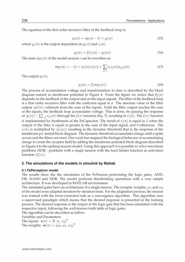
The equation of the first order recursive filter of the feedback loop is:
pi(n) = api(n − 1) + gi(n) (15)
where gi(n) is the output dependent on yi(n) and ri(n)
gi(n) = ξ(ri(n)− yi(n)) (16)
The state mpi(n) of the model neuron i can be rewritten as:
mpi(n) = −{υ + pi(n)ri(n)}+ ∑j∈τ
(ωij(n)u f ij(n)) (17)
The output yi(n):
yi(n) = ξ(mpi(n)) (18)
The process of accumulation voltage and transformation to time is described by the blockdiagram named as membrane potential in Figure 4. From the figure we notice that θ1(n)depends on the feedback of the output and on the input signals. The filter of the feedback loopis a first order recursive filter with the coeficient equal to a. The absolute value of the filteroutput (pi(n)) subtracts from the sum of the inputs. Until the filter output reaches the sumof the inputs, the feedback loop accumulates voltage. This is done, by passing the responseof |pi(n)− ∑
qj=1 xij(n)| through the ξ(υ) function (Eq. 7), resulting in ri(n). The ξ(υ) function
is implemented by hystheresis of the FeCapacitor. The result of ri(n) is equal to 1 when theoutput of the filter is equal or greater to the sum of the input signal, and 0 otherwise. Theri(n) is multiplied by (pi(n)) resulting in the dynamic threshold that is the response of themembrane po- tential block diagram. The dynamic threshold accumulates charge until a spikeoccurs and the filters are reset. Our work has mapped the biological behavior of accumulatingcharge to create the receptor field by adding the membrane potential block diagram describedin Figure 4 to the spiking neuron model. Using this approach it is possible to solve non-linearproblems (XOR - problem) with a single neuron with the hard limiter function as activationfunction (ξ(υ)).
5. The simulations of the models in simulink by Matlab
5.1 FePerceptron model
The results show the the simulation of the FeNeuron performing the logic gates, AND,OR, NAND and NOR. The model performs thresholding operations with a very simplearchitecture. It was developed in MATLAB environment.The simulated gates have an architecture of a single neuron. The synaptic weights, ω1 and ω2of the model were adapted iteration-by-iteration basis. For the adaptation process, the neuronwas trained with the error-correction rule as a convergence algorithm. This algorithm usesa supervised paradigm which means that the desired response is presented in the trainingprocess. The desired response is the output of the logic gate that has been simulated with therespective input, following the well-known truth table of logic gates.The algorithm can be described as follow:Variables and Parameters:The inputs: x(n) = [θ x1 x2]
T
The weights: w(n) = [ω0 ω1 ω2]T
238 Ferroelectrics - Applications
www.intechopen.com

Adaptive Boolean Logic Using Ferroelectrics Capacitors as Basic Units of Artificial Neurons 9
Fig. 4. The Discrete Spiking FeNeuron Model
The actual response: y(n)The desired response: d(n)The learning rate, or a positive constant less than a unit: ηThe mean square error: error(n)
1. Initialization: Randomize w(n). Perform the computations from n = 0, 1, 2, ... until themean square error is minimum.
2. Computation of the actual response with (18).
3. Adaptation Process:
w(n + 1) = w(n) + η[e(n)]x(n) (19)
e(n) = d(n)− y(n) (20)
error(n) =12 ∑
j∈Γ
e2(n) (21)
where Γ includes all neurons in the output layer of the network. In our case, only a singleneuron is used.
4. Increment time step n by one and goes back to 2.
After the training process, the weights were computed and can be used to simulate the logicgates. The learning curves are shown in Figure 5 with the computed parameters.The model performs thresholding operations with a very simple architecture. The Booleanfunctions performed by the model is soft programmable. This is accomplished by onlyadjusting the weight values of the synaptic connections. It is a very simple model thatwas easily implemented by software and can be extended to hardware implementations. Ashardware implementations, this model brings the contribution of being very simple and canperform several functions with only changing the free parameters of the structure that can besoft-programmable.
239Adaptive Boolean Logic Using Ferroelectrics Capacitors as Basic Units of Artificial Neurons
www.intechopen.com

10 Will-be-set-by-IN-TECHM
ean
Sq
uar
eE
rror
Iterations
AND GATE
Weights = [ -0.3759 0.6389 0.6389 ]
Actual Output = [ -0.0006 0.0015 0.0015 0.9981 ]
Desired Output = [ 0 0 0 1 ]
Minimum error = 0.0000059874
Mea
nS
qu
are
Err
or
Iterations
NAND GATE
Weights = [ 1.5709 -0.6503 -0.6503 ]
Actual Output = [ 1.0000 0.9988 0.9988 0.0017 ]
Desired Output = [ 1 1 1 0 ]
Minimum error = 0.0000059874
Mea
nS
qu
are
Err
or
Iterations
OR GATE
Weights = [ 0.2528 0.7089 0.7089 ]
Actual Output = [ 0.0013 0.9995 0.9995 1.0000 ]
Desired Output = [ 0 1 1 1 ]
Minimum error = 0.0000020539
Mea
nS
qu
are
Err
or
Iterations
NOR GATE
Weights = [ 0.9145 -0.6688 -0.6688 ]
Actual Output = [ 0.9986 0.0011 0.0011 -0.0009 ]
Desired Output = [ 1 0 0 0 ]
Minimum error = 0.0000052702
Fig. 5. The learning curves with the parameters for each computed logic gate. The inputswere (0 0), (0 1), (1 0) and (1 1). The threshold was considered equal to +1 for all gates.
240 Ferroelectrics - Applications
www.intechopen.com
Adaptive Boolean Logic Using Ferroelectrics Capacitors as Basic Units of Artificial Neurons 11
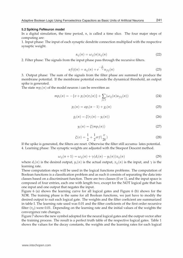
5.2 Spiking FeNeuron model
In a digital simulation, the time period, n, is called a time slice. The four major steps ofcomputing are:1. Input phase: The input of each synaptic dendrite connection multiplied with the respectivesynaptic weight.
αij(n) = ωij(n)xij(n) (22)
2. Filter phase: The signals from the input phase pass through the recursive filters.
u f ij(n) = αij(n) + e− T
τij u f ij(n) (23)
3. Output phase: The sum of the signals from the filter phase are summed to produce themembrane potential. If the membrane potential exceeds the dynamical threshold, an outputspike is generated.The state mpi(n) of the model neuron i can be rewritten as:
mpi(n) = −{υ + pi(n)ri(n)}+ ∑j∈τ
(ωij(n)u f ij(n)) (24)
pi(n) = api(n − 1) + gi(n) (25)
gi(n) = ξ(ri(n)− yi(n)) (26)
yi(n) = ξ(mpi(n)) (27)
ξ(υ) =12+
12
er f (υ
2k) (28)
If the spike is generated, the filters are reset. Otherwise the filter still accumu- lates potential.4. Learning phase: The synaptic weights are adjusted with the Steepest Descent method.
ωij(n + 1) = ωij(n) + γ(di(n)− yi(n))xij(n) (29)
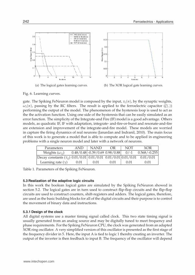
where di(n) is the desired output, yi(n) is the actual output, xij(n) is the input, and γ is thelearning rate.These computation steps will be used in the logical functions problems. The computation ofBoolean functions is a classification problem and as such it consists of separating the data intoclasses based on a discriminant function. There are two classes (0 or 1), and the input space iscomposed of four entries, each one with length two, except for the NOT logical gate that hasone input and one output that negates the input.Figure 6 (a) shows the learning curve for all logical gates and Figure 6 (b) shows for theXOR. The training phase is the same for all Boolean functions, we just have to modify thedesired output to suit each logical gate. The weights and the filter coeficient are summarizedin table I. The learning rate used was 0.01 and the filter coeficients of the first order recursivefilter (τij) were 0.01. Depending on the learning rate and the initial values of the weights theconvergence rate changes.Figure 7 shows the new symbol adopted for the neural logical gates and the output vector afterthe training process. The result is a perfect truth table of the respective logical gates. Table 1shows the values for the decay constants, the weights and the learning rates for each logical
241Adaptive Boolean Logic Using Ferroelectrics Capacitors as Basic Units of Artificial Neurons
www.intechopen.com
12 Will-be-set-by-IN-TECH
(a) The logical gates learning curves. (b) The XOR logical gate learning curves.
Fig. 6. Learning curves.
gate. The Spiking FeNeuron model is composed by the input, xi(n), by the synaptic weights,ωi(n), passing by the RC filters. The result is applied to the ferroelectric capacitor (ξ(.))performing the output of the model. The phenomenon of the hysteresis loop is used to act asthe the activation function. Using one side of the hysteresis that can be easily simulated as anerror function. The simplicity of the Integrate-and Fire (IF) model is a good advantage. Othersmodels, as quadratic IF, IF with adaptation, integrate- and-fire-or-burst and resonate-and-fireare extension and improvement of the integrate-and-fire model. These models are worriedin capture the firing dynamics of real neurons (Janardan and Indranil, 2010). The main focusof this work is to generate a model that is able to compute and to be applied in engineeringproblems with a single neuron model and later with a network of neurons.
Parameters AND NAND OR NOT XORWeights (ωij) 0.48/0.48 -0.39/0.69 0.98/0.88 0/-1 0.568/-0.255
Decay constants (τij) 0.01/0.01 0.01/0.01 0.01/0.01 0.01/0.01 0.01/0.01Learning rate (γ) 0.01 0.01 0.01 0.01 0.01
Table 1. Parameters of the Spiking FeNeuron.
5.3 Realization of the adaptive logic circuits
In this work the boolean logical gates are simulated by the Spiking FeNeuron showed insection 5.2. The logical gates are in turn used to construct flip-flop circuits and the flip-flopcircuits are used to construct counters, shift-registers and adders. The logical gates, therefore,are used as the basic building blocks for all of the digital circuits and their purpose is to controlthe movement of binary data and instructions.
5.3.1 Design of the clock
All digital systems use a master timing signal called clock. This two state timing signal isusually generated from an analog source and may be digitally tuned to meet frequency andphase requirements. For the Spiking FeNeuron CPU, the clock was generated from an adaptedXOR ring oscillator. A very simplified version of this oscillator is presented as the first stage ofthe frequency divider in 5. Here, the input A is tied to logic 1 thereby creating an inverter. Theoutput of the inverter is then feedback to input B. The frequency of the oscillator will depend
242 Ferroelectrics - Applications
www.intechopen.com

Adaptive Boolean Logic Using Ferroelectrics Capacitors as Basic Units of Artificial Neurons 13
Fig. 7. The Spiking FeNeuron (SFeN) logical gates symbols and the test vectors after training.
on the delay of the feedback signal from the input to the output. Additional adapted XORgates can be connected in scries to this one to some higher odd number to obtain the desiredfrequency of operation. As an observant reader may have noticed, a Spiking FeNeuron NOTgate could have been used in place of the Spiking FeNeuron XOR gate to derive the sameresults. The choice of the Spiking FeNeuron XOR gate does not provide any additionalbenefits over Spiking FeNeuron NOT gate but goes further to demonstrate the exibility ofthe Spiking FeNeuron logic. In standard CMOS logic, the NOT gate is almost always theonly choice of a logic component for a ring oscillator due to its few transistor count of two.Compared to the 16-transistor count for a typical CMOS XOR gate, the area and ultimately costsavings in silicon makes the CMOS NOT gate the prime choice. In Spiking FeNeuron logic,however, each of the gates is derived from a single neuron trained to perform its function,thereby allowing tremendous area savings in hardware.
5.3.2 Design of the frequency divider circuit
A multi-stage frequency divider circuit can be implemented using addition and SpikingFeNeuron XOR gates. This circuit takes a clock as an input and provides three outputswith frequencies that are a divide by 2, by 4, and by 8 of the frequency of the input signal.The design schematic is presented together with the output waveform in Figure 8. On theschematic, CLK is the input clock signal, Y2 is the divide-by-2 output, Y3 is the divide-by-4output, and Y4 is the divide-by-8 output.After training all of the gates, a function calledSpiking FeNeuron was created which has two inputs: data vector and the option to selectthe desired logical gate required to perform a desired function. The output is the result fromthe selected gate.
5.3.3 Design of the D-type flip-flop
The D-type flip-flop is basically a SET-RESET latch with a small circuit modification. On therising edge of the clock, the D input is latched to the output Q. The Spiking FeNeuron flip-floplogic circuit is shown in Figure 9. A test vector was generated to test the flip-flop in theexample 1.
243Adaptive Boolean Logic Using Ferroelectrics Capacitors as Basic Units of Artificial Neurons
www.intechopen.com

14 Will-be-set-by-IN-TECH
Fig. 8. The block diagram of the frequency divider with waveform.
MATLAB FUNCTIONfunction output = dff(data,clk)data - input vectorclk - vectoroutput - response vectorEXAMPLE 1:x = [0 0 1 1 1 0 1 0 1]clk = [0 1 0 1 0 1 0 1 0]output = dff(x,clk)output = [0 0 0 1 0 0 0 0 0]
Fig. 9. The block diagram of D-flip-flop.
5.3.4 Design of the shift-register
A shift register is constructed using the flip-flop as shown in Figure 10. The shift register is astorage register that will move or shift the bits of the stored word either to the left or the right.The simulation of the Serial-In, Serial-Out (SISO) shift register is shown in example 3 with atest vector. The test vector with a 4-bit word [0110] is being applied to the shift registers input.The initial state of the shift register flip-flop output is 0. After the first clock pulse, the datastored is shifted one position to the right and the first bit of the applied serial word is shiftedto the first position of the shifter register. After four clock pulses all the input data will bestored in the shift register. The summary of the test vector is shown in example 2.
244 Ferroelectrics - Applications
www.intechopen.com

Adaptive Boolean Logic Using Ferroelectrics Capacitors as Basic Units of Artificial Neurons 15
MATLAB FUNCTIONfunction output = shiftreg(data)data - input vectorclk - vector of the clock is generated inside the codeoutput - response vectorEXAMPLE 2:output = shiftreg([1 0 0 1])output = [0 0 0 0 1 0 0 0]
Fig. 10. The block diagram of the shift-register.
5.3.5 Design of the ALU
The ALU was construct using half-adder and full-adder circuits. The half-adder circuits wereconstructed using Spiking FeNeuron XOR and AND logic gates. The design schematic ispresented on the right side of the Figure 11 where nodes A and B are the half-adder inputs,and S and carry denote the sum and the carry output signals respectively. The full-addercircuits were constructed from Spiking FeNeuron half-adders and Spiking FeNeuron logicgates. The design schematic is shown on the left side of the Figure 11 where A, B and CIrepresent the input and carry-in signals respectively. S and carry are the sum and carryoutputs respectively. The full-adder was simulated for proper functionality. The results ofthis simulation are presented in example 3.MATLAB FUNCTIONfunction [s,carryout] = fadder(data1,data2,carryin)data1 - input vectordata2 - input vectorcarryin - input of the carrys - response vector of the sumcarryout - carry output
EXAMPLE 3:data1 = [1 0 0 1]data2 = [1 1 1 1][s, c] = f adder(data1, data2, 0)s = [1 0 0 0]c = 1
5.3.6 Design of a simple neural CPU
The Central Processing Unit contains an arithmetic-logic unit (ALU), a con- trol unit, and theregisters for storage and manipulation of the data. The design of the CPU contains the ALU,a 32-bit 8x8 memory designed from Spiking FeNeuron D flip-flops. The system configurationof the CPU is shown on Figure 12. Information on the system bus which comprise CPU,memory control and data bhts was simulated with the use of switches. The binary instructionsinclude memory and register access commands as well as ALU operational commands. The
245Adaptive Boolean Logic Using Ferroelectrics Capacitors as Basic Units of Artificial Neurons
www.intechopen.com

16 Will-be-set-by-IN-TECH
Fig. 11. The block diagram of the full adder.
microcode structure is shown on Table 2.An example of some results for the instructions given to the CPU with 8 bits data is shown(Guerreiro et al., 2008).
Fig. 12. The block diagram of the neural CPU.
Parameters NameCA R/W operation memoryCB R/W operation register
M and N Memory SelectorCR Register Selector
3/2/1/0 Data
Table 2. The microcode structure.
246 Ferroelectrics - Applications
www.intechopen.com

Adaptive Boolean Logic Using Ferroelectrics Capacitors as Basic Units of Artificial Neurons 17
6. The Model of the FePerceptron in an FPGA
Now, this work is going to show the implementation of the FePerceptron model in a FPGA.For this implementation we are going to use the DSP builder tool of Altera Corporation.The DSP Builder technology allows you to go from system definition/simulation usingthe industry-standard the MathWorks/Simulink tools to the neuron implementation. TheDSP Builder Signal Compiler block reads Simulink Model Files (.mdl) that are builtusing DSP Builder and MegaCoreÂo blocks and generates VHDL files and tool commandlanguage (Tcl) scripts for synthesis, hardware implementation, and simulation. The DSPbuilder automatically generate timing-optimized register transfer level (RTL) code based onhigh-level Simulink design descriptions (Altera, 2011).In this way, first we developed the block diagram of the Simulink model of the FePerceptronwhich is shown in the Figure 13. The model is composed by the inputs, in this case two inputsas required by a Boolean logic gate, and the weights that were generated by the simulationsin Matlab. After that the signal is summed and the output is generated passing the signalthrough the activation function that is implemented by the hystheresis of the FeCapacitor.The Figure 13 shows the implementation of the AND gate, for the other gates we only haveto change the weights values, the same structure is used. The Table 3 shows the result of thesimulations for the gates. Each gate is tested with the input vectors (Data1, Data2) and theoutput is seen by the display in Figure 13.
Fig. 13. The block diagram of the FePerceptron in Simulink (DSP Builder) for AND gate.
Data1 Data2 Display(AND) Display(NAND) Display(OR) Display(NOR)0 0 0 1 0 0.99610 1 0 0.9961 0.9973 01 0 0 0.9961 0.9973 01 1 0.9961 0 1 0
Table 3. The true table simulated by the simulink model of the FePerceptron.
The Simulink model then is converted to the RTL level code. Since the RTL level has a lot ofdetails is not possible to show all in this work, more details can be found (VHDL, 2011).
247Adaptive Boolean Logic Using Ferroelectrics Capacitors as Basic Units of Artificial Neurons
www.intechopen.com

18 Will-be-set-by-IN-TECH
7. Conclusion
The FeCapacitors have been embedded into LSIs as Ferroelectric Random Access Memory(FeRAM) and their reliability data have been accumulated for a long time. The capacitorsare high impedance device, and it is an advantage for low power consumption, besides theconfiguration can be changed after packaging.Thinking on this scenario, the FeCapacitor was choosen to be used in this work. It usesthe phenomenon of the hysteresis loop of the FeCapacitor as the activation function for theartificial neuron models. We developed two models, the FePercetron and the FeSpikingNeuron Model, both models were first simulated in Matlab, and used to simulated the booleanfunctions. Since the FePerceptron were not able to simulated the XOR gate with a singleneuron, because of the Perceptron characteristics. We were motivated to implement theFeSpiking that was based in the Extended Spiking Neuron Model and all logic gates weresimulated, including the XOR. So, an adaptive simple CPU were developed, with simplelogical circuits implemented, as registers, ALU, D-flip-flop as shown in section 4.The FePerceptron and the FeSpiking Neuron Model presented the advantaged of beingsoft-programmable. This is accomplished by only adjusting the weight values of the synapticconnections without the need of changing all the architecture. It was firstly implemented bysoftware verifying the success of the models.From both models, first we chose the FePerceptron to be implemented in hardware becauseof the simplicity of the model. For this implementation we used the DSP builder tool ofAltera Corporation. The DSP Builder Signal Compiler block read Simulink Model Filesdeveloped(.mdl) that were built using DSP Builder blocks and generated the VHDL files andthe RTL level. This is the first step to develop more complex model as the FeSpiking NeuronModel, since the basic unit of the activation function (FeCapacitor) is already developed.As hardware implementations, this model brings the contribution of being very simple, cansave in silicon area, with low power consumption and being reconfigurable in two degrees offreedom, not only as characteristics intrinsic of the FPGA, but with the reconfigurability of theboolean gates. It is only necessary to change the values of the weights and the output is goingto change to be the desired gate.
8. References
Altera Corporation. Diponível em: www.altera.com/products/dsp/dsp-builder.html.Acessado em: 10 de fevereiro de 2011.
Beiu, V.; Quintana, J. M.; Avendillo, M. J. (2003). VLSI Implementations of Threshold Logic - AComprehensive Survey, Vol. 14, pp. 1217-1243.
Bermak, D.; Martinez, D. A compact 3-D VLSI classifier using bagging threshold network ensemblesIEEE Transactions on Neural Networks 14(5) (2003) 1097âAS1109.
Brown, B.; Yu, X.; Garverick, S. A Mixed-mode analog VLSI continuous-time recurrent neuralnetwork Proceedings of International Conference on Circuits, Signals and Systems,2004,pp.104âAS108.
Chen, Z.; Haykin, S; Becker, S. Theory of monte carlo sampling-based alopex algorithms for neuralnetworks. Proceedings of IEEE International Conference on Acoustics, Speech, andSignal Processing, pp. 17-21.
Dias, Fernando Morgado; Antunes, Ana; Manuel Mota, Alexandre. Artificial neural networks: areview of commercial hardware Engineering Applications of Artificial Intelligence, v.17n.8, p.945-952, December, 2004
248 Ferroelectrics - Applications
www.intechopen.com

Adaptive Boolean Logic Using Ferroelectrics Capacitors as Basic Units of Artificial Neurons 19
Duong, T.A. Cascade error projection: an efficient hardware learning algorithm Proceedings of theIEEE International Conference on Neural Networks, vol. 1, Perth, Australia, 1995, pp.175-178.
Duong, T.A.; Stubberud, A.R., Convergence analysis of cascade error projection: an efficienthardware learning algorithm. International Journal of Neural System. v10 i3. 199-210.
D’Acierno, A. Back-propagation learning algorithm and parallel computers: the CLEPSYDRAmapping scheme. Neurocomputing. v31. 67-85.
Fakhraie, S.M.; Farshbaf, H; Smith, K.C. Scalable closed-boundary analog neural networks. IEEETransactions on Neural Networks. v15. 492-504.
Glesner, M.; Poechmueller, W. Neurocomputers: An Overview of Neural Networks in VLSI. 1994.Chapman and Hall, London.
Guerreiro, Ana Maria GuimarÃces; McMillan, Larry; Araujo, Carlos A Paz de. Adaptive LogicSynthesis by Ferroelectric Spiking Neuron Circuits. Integrated Ferroelectrics, v. 100, p.238-253, 2008.
Haykin, S. (1998). Neural Networks: A Comprehensive Foundation. Prentice Hall, 2nd Edition.Heemskerk, J. Overview of neural hardware Neurocomputers for Brain-Style Processing, Design,
Implementation and Application, 1995.Kumar, V.; Shekhar, S.; Amin, M. B. A Scalable Parallel Formulation of the Backpropagation
Algorithm for Hypercubes and Related Architectures IEEE Transactions on Parallel andDistributed Systems, v.5 n.10, p.1073-1090, October 1994.
Ienne, Paolo; Cornu, Thierry; Kuhn, Gary. Special-purpose digital hardware for neural networks: anarchitectural survey Journal of VLSI Signal Processing Systems, v.13 n.1, p.5-25, Aug.1996.
Jabri, Marwan; Flower, Barry. Weight perturbation: An optimal architecture and learning techniquefor analog vlsi feedforward and recurrent multilayer networks. Neural Computation, v.3n.4, p.546-565, Winter 1991.
Janardan, Misra; Indranil, Saha. Artificial neural networks in hardware: A survey of two decadesof progress. Journal Neurocomput. vol 74. 2010. ISSN: 0925-2312. Elsevier SciencePublishers B. V.
Kung, S.Y. Digital Neural Networks Prentice-Hall, Upper Saddle River, NJ, USA, 1992.Lehmann, Torsten; Bruun, Erik; Dietrich, Casper. Mixed analog/digital matrix-vector multiplier
for neural network synapses Analog Integrated Circuits and Signal Processing, v.9 n.1,p.55-63, Jan. 1996.
Lamela, H.; and Ruiz-Llata, M. Optoelectronic neural processor for smart vision applications.Imaging Science Journal. v55 i4. 197-205.
Lenne, P. Digital hardware architectures for neural networks Speedup Journal 9(1)(1995)18âAS25.McCulloch, W. S.; Pitts, W. (1943). A logical calculus of the ideas immanent in nervous activity,
Bull. Math. Biophysiol., vol. 5, pp. 115-133.Mead, C. Analog VLSI and Neural Systems Addison-Wesley,Boston,MA, USA, 1989.Miller, S. L.; Schwank, J. R.; Nasby, R. D.; and Rodgers, M. S. (1991). Modeling Ferroelectric
capacitor switching with asymmetric nonperiodic input signals and arbitrary initialconditions. J. Appl. Phys., vol. 70, no. 5, pp. 2949-2860.
Moerland, P.D.; Fiesler, E; and Saxena, I. Incorporation of liquid-crystal light valve nonlinearitiesin optical multilayer neural networks. Applied Optics. v35. 5301-5307.
Nedjah, Nadia; Mourelle, Luiza de Macedo. Reconfigurable hardware for neural networks: binaryversus stochastic Neural Computing and Applications, v.16 n.3, p.249-255, May 2007.
249Adaptive Boolean Logic Using Ferroelectrics Capacitors as Basic Units of Artificial Neurons
www.intechopen.com

20 Will-be-set-by-IN-TECH
Patnaik, L.M.; Rao, R.N. Parallel implementation of neocognitron on star topology: theoretical andexperimental evaluation. Neurocomputing. v41. 109-124.
RÃak, ÃAdÃam; SoÃss, BalÃazs Gergely; Cserey, GyÃurgy. Stochastic bitstream-basedCNN and its implementation on FPGA International Journal of Circuit Theory andApplications, v.37 n.4, p.587-612, May 2009.
Rosemblatt, F. (1958). The perceptron: A probabilistic model for information storage and organizationin the brain. Psych. Revue, vol. 65, pp. 386-408.
Sheikholeslami, A.; Gulak, P. Glenn (1997). A Survey of Behavioral Modeling of FerroelectricCapacitors. IEEE Trans. on Ultrasonics, Ferroelectrics, and Frequency Control vol. 44,no. 4, pp. 917-923.
Schmid, A.; Leblebici, Y.; and Mlynek, D. A mixed analog digital artificial neural network with onchip learning. IEE Proceedings-Circuits, Devices and Systems. 2004. v146. 345
Schrauwen, B.; D’Haene, M. Compact digital hardware implementations of spiking neural networksJ. Van Campenhout (Ed.), Sixth FirW Ph.D. Symposium, 2005, in CD.
Shibata, T.; Ohmi, T. (1991). An intelligent MOS transistor featuring gate-level weighted sumand threshold operations. Technical Digest of International Electron Devices Meeting,Washigton DC, pp. 919-922.
Smieja, F. J. Neural network constructive algorithms: trading generalization for learning efficiencyCircuits, Systems, and Signal Processing, v.12 n.2, p.331-374, 1993.
Sundararajan, N.; Saratchandran, P. Parallel Architectures for Artificial Neural Networks:Paradigms and Implementations IEEE Computer Society Press, Los Alamitos, CA, 1998.
Strey, Alfred; Avellana, Narcis. A New Concept for Parallel Neurocomputer ArchitecturesProceedings of the Second International Euro-Par Conference on ParallelProcessing-Volume II, p.470-477, August 26-29, 1996.
Tokes, S.; OrzÚ, L.; Vr, G.; Roska, T. Bacteriorhodopsin as an analog holographic memory for jointfourier implementation of CNN computers Technical Report DNS-3-2000, Computer andAutomation Research Institute of the Hungarian Academy of Sciences, Budapest,Hungary, 2000.
Valle, M. Smart Adaptive Systems on Silicon. 2005. Springer, Dordrecht, The Netherlands.Verleysen, Michel; Thissen, Philippe; Voz, Jean-Luc; Madrenas, Jordi. An Analog Processor
Architecture for a Neural Network Classifier, IEEE Micro, v.14 n.3, p.16-28, June 1994.VHDL. Diponível em: ftp://alan:[email protected]. Acessado em: 20 de fevereiro de
2011.Zhu, J.; Sutton, P. FPGA implementations of neural networks-a survey of a decade of progress.
Field-Programmable Logic and Applications, vol. 2778. pp. 1062-1066.Yang, F.; Paindavoine, M. Implementation of an RBF neural network on embedded systems: real-time
face tracking and identity verification. IEEE Transaction on Neural Networks. v14 i5.1162-1175.
250 Ferroelectrics - Applications
www.intechopen.com

Ferroelectrics - ApplicationsEdited by Dr. Mickaël Lallart
ISBN 978-953-307-456-6Hard cover, 250 pagesPublisher InTechPublished online 23, August, 2011Published in print edition August, 2011
InTech EuropeUniversity Campus STeP Ri Slavka Krautzeka 83/A 51000 Rijeka, Croatia Phone: +385 (51) 770 447 Fax: +385 (51) 686 166www.intechopen.com
InTech ChinaUnit 405, Office Block, Hotel Equatorial Shanghai No.65, Yan An Road (West), Shanghai, 200040, China Phone: +86-21-62489820 Fax: +86-21-62489821
Ferroelectric materials have been and still are widely used in many applications, that have moved from sonartowards breakthrough technologies such as memories or optical devices. This book is a part of a four volumecollection (covering material aspects, physical effects, characterization and modeling, and applications) andfocuses on the application of ferroelectric devices to innovative systems. In particular, the use of thesematerials as varying capacitors, gyroscope, acoustics sensors and actuators, microgenerators and memorydevices will be exposed, providing an up-to-date review of recent scientific findings and recent advances in thefield of ferroelectric devices.
How to referenceIn order to correctly reference this scholarly work, feel free to copy and paste the following:
Alan P. O. da Silva, Cicilia R. M. Leite, Ana M. G. Guerreiro, Carlos A. Paz de Araujo and Larry McMillan(2011). Adaptive Boolean Logic Using Ferroelectrics Capacitors as Basic Units of Artificial Neurons,Ferroelectrics - Applications, Dr. Mickaël Lallart (Ed.), ISBN: 978-953-307-456-6, InTech, Available from:http://www.intechopen.com/books/ferroelectrics-applications/adaptive-boolean-logic-using-ferroelectrics-capacitors-as-basic-units-of-artificial-neurons

© 2011 The Author(s). Licensee IntechOpen. This chapter is distributedunder the terms of the Creative Commons Attribution-NonCommercial-ShareAlike-3.0 License, which permits use, distribution and reproduction fornon-commercial purposes, provided the original is properly cited andderivative works building on this content are distributed under the samelicense.