adaptive compensator for a vehicle driven by two independent motors
TRANSCRIPT
8/7/2019 Adaptive Compensator for a vehicle driven by two independent motors
http://slidepdf.com/reader/full/adaptive-compensator-for-a-vehicle-driven-by-two-independent-motors 1/18
1
COMPENSATION TECHNIQUES FOR A VEHICLE SYSTEM
DRIVEN BY INDEPENDENT DC MOTORS
MOHAMMED AFZAL BIYABANI (EE)
G200904750KING FAHD UNIVERSITY OF PETROLEUM AND MINERALS (KFUPM)
8/7/2019 Adaptive Compensator for a vehicle driven by two independent motors
http://slidepdf.com/reader/full/adaptive-compensator-for-a-vehicle-driven-by-two-independent-motors 2/18

8/7/2019 Adaptive Compensator for a vehicle driven by two independent motors
http://slidepdf.com/reader/full/adaptive-compensator-for-a-vehicle-driven-by-two-independent-motors 3/18
3
tasks. All the tasks of the AGV will be controlled by thecomputer.AGVs can also be programmed to follow markers or wireson the floor, or use vision of lasers. Following complex paths theobjective is to transfer loads to remote areas under computer control.Conveyors doesn¶t give flexibility for such an operation and Robotsdoesn¶t offer mobility.
AGV system has attracted many researchers. The three areas whichattracted the researchers the most are 1) Construction 2) Management and 3) Control of the AGVs. Due to changes in the dynamics of load,the control method selected is very important in order to withstanddynamics. The parameters of the system changes due to disturbancesduring the operation with time and also because of dynamics changes
that comes from load with time to time. It has a great theoreticalmeaning and practical value in solving the control problem of thevehicle systems. Therefore, the control type can be chosen properly toovercome parameter change and sudden disturbance.
Components of AGVs:
y Main components of Automated Guided Vehicle can be dividedinto following:
y The Vehicle ± No operator
y The guide path ± The path for the AGV
y The control unit ± Monitors and Directs systemoperationsincluding feedback on moves, inventory, and vehicle status.
y The computer interface ± Interfaces with other mainframe hostcomputer, the automated storage and retrieval system (AS/RS),
and the flexible manufacturing system.
Adaptive Control:
Adaptive control involves modifying the control law used by acontroller to cope with the fact that the parameters of the system being

8/7/2019 Adaptive Compensator for a vehicle driven by two independent motors
http://slidepdf.com/reader/full/adaptive-compensator-for-a-vehicle-driven-by-two-independent-motors 4/18
4
controlled are slowly time-varying or uncertain. For example, as anaircraft flies, its mass will slowly decrease as a result of fuelconsumption; we need a control law that adapts itself to suchchanging conditions. Adaptive control is different from robust controlin the sense that it does not need a priori information about the boundson these uncertain or time-varying parameters; robust controlguarantees that if the changes are within given bounds the control lawneed not be changed, while adaptive control is precisely concernedwith control law changes.
An adaptive controller is a controller with adjustable parameters and amechanism for adjusting the parameters. An adaptive Control systemcan be thought of as having two loops. One loop is a normal feedback
with the process and the controller. The other loop is the parameter adjustment loop. Block diagram of an adaptive system is shown in the
below figure.
Classification of adaptive control techniques:
In general one should distinguish between:
1. Feed forward Adaptive Control2. Feedback Adaptive Control
8/7/2019 Adaptive Compensator for a vehicle driven by two independent motors
http://slidepdf.com/reader/full/adaptive-compensator-for-a-vehicle-driven-by-two-independent-motors 5/18
5
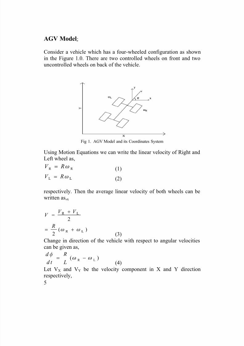
AGV Model:
Consider a vehicle which has a four-wheeled configuration as shown
in the Figure 1.0. There are two controlled wheels on front and twouncontrolled wheels on back of the vehicle.
Fig 1. AGV Model and its Coordinates System
Using Motion Equations we can write the linear velocity of Right andLeft wheel as,
R R V R [ ! (1)
V R [ !
(2)
respectively. Then the average linear velocity of both wheels can bewritten as,x
¡ ¢
¡ ¢
2
( )2
V V V
R[ [
!
!
(3)
Change in direction of the vehicle with respect to angular velocitiescan be given as,
R L( )d R
d t L
J [ [!
(4)
Let VX and VY be the velocity component in X and Y directionrespectively,

8/7/2019 Adaptive Compensator for a vehicle driven by two independent motors
http://slidepdf.com/reader/full/adaptive-compensator-for-a-vehicle-driven-by-two-independent-motors 6/18
6
x
R L
cos( )
( ) cos( )2
dxV V
d t
R
J
[ [ J
! !
! (5)
R L
sin( )
( )sin( )2
y
d yV V
d t
R
J
[ [ J
! !
! (6)
Each of the front wheel is independent and are driven by separatelyexcited DC motors, through a gear box. The torque transferred fromthe motor to gearbox can be written as follows:
2
LOAD2
m mm m m
d d T J B T
d t d t
U U!
(7)
Where,2
2 2LOAD 2 22 | |
m m mC
m
d d T n J n B nF
d t d t
U U U
U!
&
& (8)
Where, FCis the Coulomb torque constant
n is the reduction ratio of the gearbox
Substitute TLOADinto motor torque Tm we get,2
2
2 2
22
( )
( ) ( )
mm m
mm C m
d T J n J
d t
d B n B nF s ign
d t
U
UU
!
&
(9)Above equation can be deduced to,
2
1 2 32( )m m
m m
d d sign T
d t d t
U UL L U L!
&
(10)
Where,

8/7/2019 Adaptive Compensator for a vehicle driven by two independent motors
http://slidepdf.com/reader/full/adaptive-compensator-for-a-vehicle-driven-by-two-independent-motors 7/18
7
22
1 22
( )
( )m
m
B n B
J n J L
!
2 22( )
C
m
n F
J n J L !
3 22
1
( )m
J n J L !
(11)
From above equations we can write the angular velocities of Rightand Left wheel as, i.e., from Eq. (10)
R 1 R 2 R 3( ) R
s i g n T [ L [ L [ L! & (12)
£
1£
2£
3( ) L
s ig n T [ L [ L [ L! &
(13) And from Eq. (3), (4), (12) and (13)
¤ ¥
1¤ ¥
2¤ ¥
3¤ ¥
( ) [ ( )2 2
( ( ) ( ) )
( ) ]
R Rv
s ig n s ig n
T T
[ [ L [ [
L [ [
L
! !
& &&
(14)
R L 1 R L
2 R L
3 R L
( ) [ ( )
( ( ) ( ))
( )]
R R
L L
s ig n s ig n
T T
J [ [ L [ [
L [ [
L
! !
&& & &
(15)
Where 1, 2, 3 are constants and R and L are the right and leftwheel angular velocity, respectively.
Control of the Vehicle System:
As shown in the vehicle control system block diagram, the twooutputs of the controller are used to calculate the torque of eachmotor.The torque equation for each wheel is given as:
Right wheel torque: TR = (1/2)*(uv+u) (16)Left wheel torque:TL= (1/2)*(uv-u) (17)

8/7/2019 Adaptive Compensator for a vehicle driven by two independent motors
http://slidepdf.com/reader/full/adaptive-compensator-for-a-vehicle-driven-by-two-independent-motors 8/18
8
The below shows the control of the vehicle system depends on thedirection angle () control and vehicle velocity control (v). Actualvelocity, actual angle and their reference values are used by thecontroller. Adaptive controller controls velocity and angle that
produces 2 outputs(uv and u).
An Adaptive compensator based on fuzzy identifier and
controller for the vehicle system:
Using Takagi-Sugeno fuzzy systems, an adaptive compensator is proposed for vehicle control system. With the help of Systemidentification, a Takagi-Sugeno model is found for the plant.Globalasymptotically equilibirium is obtained by constructing compensator
for the closed loop system. The parameters of Takagi-Sugeno areadjusted by using an online method in order to match the behaviour of the system. The parameters of the identifier model are employed in astandard paralle-distributed compensator by using certaintyequivalence principles. In this way, the identifier model does not needto have any initial knowledge about the vehicle system. As theidentifier becomes more accurate, the controller parameters of thecompensator will be adjusted, and the controller will succeed.Withthis approach proposed, the closed-loop system will be immune todisturbance, parameter uncertainties and load changes.
Fuzzy Identifier model:
Takagi±Sugeno fuzzy system has any linear mapping as its outputfunction. Considering this fuzzy system as a nonlinear interpolator

8/7/2019 Adaptive Compensator for a vehicle driven by two independent motors
http://slidepdf.com/reader/full/adaptive-compensator-for-a-vehicle-driven-by-two-independent-motors 9/18
9
between R linear systems, one mapping is to have a linear dynamicsystems the output function so that the ith rule has the followingform(one rule of identifier model would be):
which is formed as discrete-time linear systems. Here, uv(k) and uj(k)are the plant inputs and v(k) and j(k) are plant outputs. Ai and Bi arethe linguistic values; ai, bi, ci, di, (i = 1,2 ,y«,R) are the parametersof the consequents. Vi(k+1) and i(k+1) 1Þ are the identifier modeloutputs considering only rule i. Suppose that µi denotes premisecertainty for the rule i. Using center-average defuzzification, we getthe following identifier model outputs:
(18), (19)
Let us define followings,
(20)
(21)Then,
(22),(23)where v(k+1) and (k+1) are the identifier model outputs. v, , v
and ,are defined as

8/7/2019 Adaptive Compensator for a vehicle driven by two independent motors
http://slidepdf.com/reader/full/adaptive-compensator-for-a-vehicle-driven-by-two-independent-motors 10/18
10
(24),(25),(26)&(27)
An on-line method, recursive least square (RLS) is used to adjust theai, bi, ci and di parameters since they enter linearly. The RLSalgorithm with update formulas is given by
(28) to (33)
where I is the identity matrix and is the weighting factor. Note thatwe have adjusted the time indices in these equations to solve theidentification problem and to estimate the output of the identifier model, i.e. v(k+1) and (k+1).
Design of fuzzy controller:
For the controller, we use Takagi±Sugeno rules in the form
where v*(k) and *(k) are the reference values of v(k) and (k):uvi(k) and ui(k) which are controller outputs considering rule i, They

8/7/2019 Adaptive Compensator for a vehicle driven by two independent motors
http://slidepdf.com/reader/full/adaptive-compensator-for-a-vehicle-driven-by-two-independent-motors 11/18
11
are linear functions of their arguments that depend on reference inputsand past plant outputs. Our controllers that are tuned are given by
(34),(35)The Gaussian input membership functions on the universes of discourse v(k) and (k) are used in the form
(36),(37)As there is only one input, the membership function certainty is the
premise membership function certainty for a rule
and
These cause saturation of the outermost input membership functions. Now using a certainty equivalence approach for the controller system,view each rule of the controller as if it controls only one rule of the
plant and assume identifier to be accurate. In particular, Assume thatv`(k) = v(k) and v¶i(k) = vi(k), where vi(k) represents ith component of

8/7/2019 Adaptive Compensator for a vehicle driven by two independent motors
http://slidepdf.com/reader/full/adaptive-compensator-for-a-vehicle-driven-by-two-independent-motors 12/18
12
the plant model, so that the identifier also perfectly estimates thedynamics represented by each rule in the plant.operation of th plantnear its ith rule and there is little or no affect fromits other rules, thenv (k) = v
i(k).
Thus we obtain
(38)
We pick k 1i and k 2i for each i = 1,2 ,«,R such that the pole of theclosed-loop system is at 0.1 and the steady-state error between v*(k)and v(k) is equal to zero. In particular, if Vi(k) and V*(k) are the z-transforms of vi(k) and v*(k), respectively then,
(39)
ChooseK 2i bi - ai = -0.1 (40)
In order to get the pole placement,Picking
(41)
where subscript i = 1,2,...,R at each time step using the estimates of a i and bi from the identifier. Ensure bi>0 that could be done byspecifying a priori some ¯b>0: By adding a rule to the adaptationscheme that if at some time the RLS updates any bi so that it becomesless b, we let it equal ¯b: In this way, the lowest value bi will take ¯b.
To have a zero steady-state error, we want vi(k+1) = vi(k) = v*(k) for a large k and i = 1,2 ,«,R.FromEq. (38)
(42)Thus, our controller designer will choose

8/7/2019 Adaptive Compensator for a vehicle driven by two independent motors
http://slidepdf.com/reader/full/adaptive-compensator-for-a-vehicle-driven-by-two-independent-motors 13/18
13
(43)
Eqs. (41) and (43) specify the controller designer for the indirectadaptive scheme, values of ai and bi are provided by identifier at eachtime step so that k 1i and k 2i can be updated at each time step. Note thatthe modifications to Eq. (41) with ¯b will also ensure that Eq. (43)will not be divided by zero.The above approach that is used to calculate the gains of the uv(k) can
be used to obtain the gains of the controller u(k) and they can bedefined as follows
(44)
(45)
We have used three rules for fuzzy identifier and controller (R = 3).We choose v(0) =[0, 2, 4, 6, 8, 10] T, (0) = [0, 2, 4, 6, 8, 10] T,Pv(0)= 2000I; P(0)= 2000I and = 1; where I is the identity matrix.The choice of v(0) and (0) is arbitrary. 1=-1, 2 = 0, 3 = 1 and
1= 0:5; 2= 0.5 are defined for membership functions. The results of the RLS-based adaptive fuzzy control of the vehicle systemare shownin Figs. 3±5.Fig 3. Shows the performance of the controller for a trapezoidalvelocity reference and a sinusoidal direction angle reference at thesame time. It can be seen that for the complex references theresponses of the vehicle systemare very good and robust. Thetrapezoidal reference is important as the control system is tested for anincreasing and decreasing velocity period. Also, a sinusoidal
referenceis chosen for the angle of vehicle direction that is verycomplex path for the direction control. Although both the referencesof trapezoidal velocity and sinusoidal direction angle are applied tothe vehicle systemat the same time, the response of the controlsystemis very satisfactory and the controller signals are smooth andcontinuous. Fig. 4 shows the trajectory response of the vehicle system

8/7/2019 Adaptive Compensator for a vehicle driven by two independent motors
http://slidepdf.com/reader/full/adaptive-compensator-for-a-vehicle-driven-by-two-independent-motors 14/18
14
for the references given in Fig. 3. It seems that both the reference andcalculated trajectories are on top of each other. The control system istested under loading conditions and sudden changes of references inFig. 5. Fig 5 shows, a load is applied to the vehicle at 5th second andit is demonstrated that the control input produces a sharp and robustresponse that prevent the overshoots and deeps at vehicle velocityvariations. In addition, as seen from Fig. 5, when the references of thevelocity and direction angle are changed suddenly at every 10thsecond, the controller is still observed to produce responses very well.
Fig. 3. Response of the controller for the trapezoidal and sinusoidal references.(a) variations of actual and reference velocities (v, vr ), (b) variations of actual andreference direction angles (r , ), (c) control input (uv), (d) control input (u).
Fig. 4. Trajectory tracking response of the vehicle control system.

8/7/2019 Adaptive Compensator for a vehicle driven by two independent motors
http://slidepdf.com/reader/full/adaptive-compensator-for-a-vehicle-driven-by-two-independent-motors 15/18
15
Fig. 5. Response of the adaptive fuzzy controller for step references. (a)variations of the actual and reference velocities (v, vr ), (b) variations of the actual and reference direction angles (r , ), (c) control input (uv),
(d) control input (u).
Model using Lead-Lag Compensator:
Fig 6. Lead Lag Compensator Design
The block diagram consists of following components:
y Reference trajectory generator
y Comparator
y Lead ± Lag Compensator
y Vehicle System
Reference Trajectory Generator:It provides the reference inputs to thecomparator of the developed model. If the reference input is instead

8/7/2019 Adaptive Compensator for a vehicle driven by two independent motors
http://slidepdf.com/reader/full/adaptive-compensator-for-a-vehicle-driven-by-two-independent-motors 16/18
16
changed smoothly by generation of a reference trajectory, thesaturation of the control signal can be avoided, and the response can
be improved.
Comparator:A Comparator is a device which compares two signalsand switches its output to indicate which is larger. Here, the functionof Comparator is to compare the reference input and the output signalwhich is given as an input the Lead - Lag Compensator block.
Lead ± Lag Compensator:A lead±lag compensator is a component in acontrol system that improves an undesirable frequency response in afeedback and control system. It is a fundamental building block inclassical control theory. Here, we have designed the compensator such
that it receives the input from Comparator, then its parameters aretuned (adjustment mechanism) in such a way the output of thecompensator is given to the Vehicle system and then the time varying
parameters of vehicle system are controlled by the Compensator.
Vehicle System:The designed vehicle system receives the input signalfrom lead lad compensator and the ouput is controlled if there are anychanges in the systems speed with respect to the desired speed. If thedesired speed is same as the Vehicle system speed, then thecompensator receives no signal from the comparator, hence, it is notincluded in the system. If there is a difference between the speeds(desired speed and vehicle system speed) then comparator gives theoutput, which is the input to the compensator block and thus, thecompensator is included into the system and it controls the speed of the system to desirable speed. As the vehicle system speed becomesequal to the desired speed then there is no need of controller and thusits output becomes zero and it is not included into the system.

8/7/2019 Adaptive Compensator for a vehicle driven by two independent motors
http://slidepdf.com/reader/full/adaptive-compensator-for-a-vehicle-driven-by-two-independent-motors 17/18
17
Results:
Fig 6. Responses of a Lead Lag Compensator Design.
Conclusion:
An adaptive compensator based on Takagi-Sugeno fuzzyidentification system and control is applied to the vehicle systemdriven by two independent DC motors. Outputs of each controller give the torque of the each motor. The system is designed and thecontrol system is tested for loading conditions and complexreferences. It is shown that the response of the proposed adaptivefuzzy control system is very fast and very robust against disturbanceand change of references. The results show that the produced control
signals prevent deeps and overshoots at the direction angle andvelocity of the vehicle systemwhen load and references are suddenlychanged. Hence, it means that the proposed identification model andcontrol structure is working very well. Different adaptive controls can
be developed based on the requirements; Main idea was to design theadaptive compensator for the control of velocity and direction of the

8/7/2019 Adaptive Compensator for a vehicle driven by two independent motors
http://slidepdf.com/reader/full/adaptive-compensator-for-a-vehicle-driven-by-two-independent-motors 18/18
18
vehicle system. The control of the vehicle system is also done by leadlag compensator and the results are efficient.
References:
1. Adaptive Control for Partially Known systems, Theory andapplications by Carlos A. Canudas De Wit
2. Adaptive Control by Karl J. Astrom and Bjorn Wittenmark 3. R.K. Miller, Automated guided vehicles and automated
manufacturing4. B.Z. Sandler, Robotics, Designing the mechanism for
Automated Machinery
5. E.T. Baugartner, S.B. Skaar, An autonomous vision basedmobile robot
6. Adaptive Control and its applications Wikipedia7. J. Kook Lim, J. Mook Lim, K. Yoshimoto, K. Hwan Kim, T.
Takahashi, Designing guide-path networks for automatedguided vehicle system
8. M.K. Guven, Fuzzy Identification and its Application toControl.
9. C.K. Li, Hongmin Chao, Y.M. Hu, A.B. Rad, Output
tracking control of mobile robots based on adaptive backstepping and high order sliding modes10. Modern Control theory by S.M. Tripathi11. Control systems by Nagoor Kani12. Linear system Theory and Design by Chi Tsong Chen.