adaptive control method for path-tracking · pdf fileinternational journal of ... adaptive...
TRANSCRIPT
International Journal of InnovativeComputing, Information and Control ICIC International c⃝2011 ISSN 1349-4198Volume 7, Number 7(B), July 2011 pp. 4423–4434
ADAPTIVE CONTROL METHOD FOR PATH-TRACKING CONTROLOF AN OMNI-DIRECTIONAL WALKER COMPENSATING
FOR CENTER-OF-GRAVITY SHIFTS AND LOAD CHANGES
Renpeng Tan1, Shuoyu Wang1, Yinlai Jiang1, Kenji Ishida2
Masakatsu G. Fujie3 and Masanori Nagano4
1School of Systems EngineeringKochi University of Technology
No. 185, Miyanokuchi, Tosayamada, Kami, Kochi 782-8502, [email protected]; {wang.shuoyu; jiang.yinlai }@kochi-tech.ac.jp
2Department of Physical Medicine and RehabilitationKochi University
2-5-1 Akebono-cho, Kochi 780-8520, [email protected]
3Department of Modern Mechanical EngineeringWaseda University
59-309, 3-4-1 Okubo, Shinjyuku, Tokyo 169-8555, [email protected]
4Soai Co., Ltd.266-2 Shigekura, Kochi, Kochi 780-0002, Japan
Received June 2010; revised October 2010
Abstract. In previous studies, an omni-directional walker was developed for walkingrehabilitation. Walking training programs are stored in the walker so that rehabilitationcan be carried out without a physical therapist. However, the walker sometimes straysfrom the predefined path because of center-of-gravity shifts and load changes. It is neces-sary for the walker to precisely follow the paths defined in the walking training programsto guarantee the effectiveness of rehabilitation and user safety. Therefore, this paperdescribes a path-tracking control method for the omni-directional walker to compensatefor center-of-gravity shifts and load changes. First, the kinematics and kinetics of theomni-directional walker motion are presented. Second, an adaptive control strategy isproposed. Finally, simulations show that the walker can be controlled accurately by usingthe proposed method.Keywords: Omni-directional walker, Adaptive control, Load change, Center-of-gravityshift, Path tracking
1. Introduction. In an aging society with a low birthrate, such as that found in Japan,an increasing number of people suffer from walking impairments due to illness or accident.Therefore, the demand for walking rehabilitation has been increasing in recent years.However, Japan has a serious shortage of physical therapists. Therefore, developing awalking training machine that can efficiently conduct a variety of training programs ishighly desirable.
Walking is a complex combination of motions [1], which includes not only forward andbackward motions, but also right and left motions, oblique motions and rotations. Thusfar, walkers for walking rehabilitation have only allowed a few basic motions with the helpof crutches, canes, and parallel bars. This holds true for lift walkers [2], active walkers [3],the SRC walker (Arizono Orthopedic Supplies Co., Japan) and the posture control walker
4423
4424 R. P. TAN, S. Y. WANG, Y. L. JIANG, K. ISHIDA, M. G. FUJIE AND M. NAGANO
(Pacific Supply Co., Japan). The whole process of rehabilitation using these walkersrequires the assistance of physical therapists, which is a heavy burden on the therapists,both mentally and physically. If a walker training machine for rehabilitation that doesnot require direct assistance of a therapist and that accommodates these diverse motiongroups can be designed, then faster recoveries can be achieved and the burden on physicaltherapists will be reduced.In previous studies, the authors of the present paper, along with colleagues, developed
an omni-directional walker [4]. This walker allows omni-directional movement. Trainingprograms are stored in the walker so that rehabilitation can be carried out without thepresence of physical therapists. Its effectiveness in walking rehabilitation was verified byclinical tests [5-7]. However, the accuracy of the path tracking of this walker needed tobe improved to make it possible for the walker to follow precisely the exercise programsprescribed by physical therapists. This paper focuses on the accuracy of path trackingfor a nonlinear system taking into consideration center-of-gravity shifts and load changescaused by the users.Optimal control [8,9] can achieve an optimal value of an evaluation indicator, but the
value of the plant parameters needs to be known for the design of the controller. AlthoughPID control [10] does not require the exact values of the plant parameters, because theoptimal value of the PID control parameters can be obtained by iterative adjustment, theparameters of the controller need to be re-adjusted once the plant parameters change.Adaptive control [11,12] does not need the exact values of the plant parameters and canadapt to parameter uncertainties by measuring and adjusting the parameters automat-ically. Therefore, when the parameters are variable, adaptive control is more suitable.In the case of the omni-directional walker, the center-of-gravity shifts and load changescaused by the users during walking training introduce the parameter variability. Linearmodel reference adaptive control cannot be applied to the omni-directional walker, whichis a nonlinear system. Inspired by Slotine and Li [13], we have now developed an originalcontrol method for the omni-directional walker.In this paper, an adaptive control strategy is proposed for the omni-directional walker,
which is a slowly time-varying nonlinear system. For a walker with parametric, structural,and environmental uncertainties, the proposed adaptive control provides adaptation mech-anisms that adjust a controller to achieve the desired system performance. This paper isorganized as follows: Section 2 describes the design of the structure, the kinematics, andthe kinetics analysis of the omni-directional walker; Section 3 presents an adaptive controlstrategy to adapt to the center-of-gravity shifts and load changes caused by users duringrehabilitation; Section 4 shows simulations of the proposed method with center-of-gravityshifts and load changes; the simulation results show that the proposed adaptive controlmethod is feasible and effective; a brief conclusion is given in Section 5.
2. Structure of the Omni-directional Walker and Modeling.
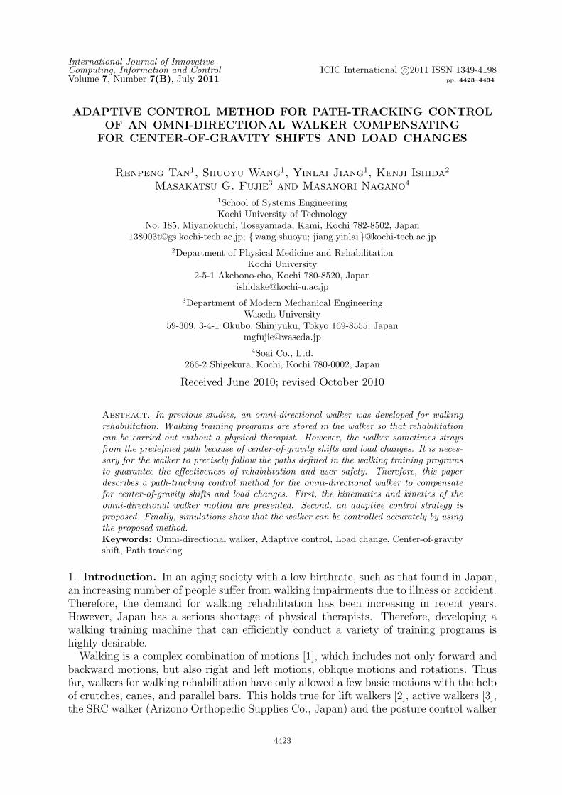
2.1. Omni-directional walker. The structure of the omni-directional walker is shownin Figure 1. The most important feature of the walker is the use of omni-directionalwheels. An arrangement of four omni-wheels at the bottom of the walker body enablesthe walker to move in any direction while maintaining its orientation.The physical parameters of the omni-directional walker are listed in Table 1. Two
telescopic poles are designed to support both the upper part of the walker and the loadfrom the user. The walker height is adjustable from 900 to 1200 mm to accommodate thedifferent heights of the users. The mass of the walker is 58 kg and the maximum speed isset to 0.25 m/s to ensure user safety.
CONTROL METHOD FOR PATH-TRACKING CONTROL OF OMNI-DIRECTIONAL WALKER4425
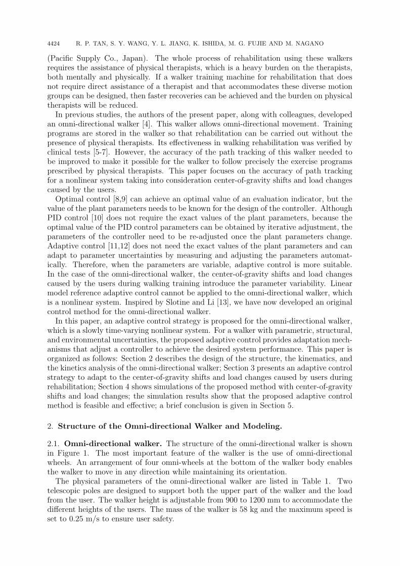
Figure 1. Omni-directional walker and one of its omni wheel
Table 1. Physical parameters of the walker
Parameter ValueHeight 900 – 1200 mmArm L 400 mmMass M 58 kg
Maximum load m 80 kgMaximum speed v 0.25 m/s
Figure 2. Structural model of the omni-directional walker
2.2. Motion modeling. To develop the control law for the omni-directional walker,we derive the necessary kinematic and kinetic equations. The coordinate settings andstructural model are shown in Figure 2.
The parameters and coordinate system are as follows:∑(x, y, O): Absolute coordinate system.∑(x′, y′, G): Translation coordinate system of
∑(x, y, O).
v: Speed of the omni-directional walker.vi: Speed of an omni-directional wheels (i = 1, 2, 3, 4).fi: Force on each omni-directional wheel.L : Distance from the center-of-gravity of the walker to each omni-wheel.α: Angle between the x′-axis and the direction of v.θ: Angle between the x′-axis and the position of the first omni-directional wheel.G: Center-of-gravity of the walker.r0: Distance between G and the center-of-gravity caused by load.

4426 R. P. TAN, S. Y. WANG, Y. L. JIANG, K. ISHIDA, M. G. FUJIE AND M. NAGANO
Using the coordinate system shown in Figure 2, a kinematic analysis is carried out forthe four-input, three-output nonlinear system. The kinematic equations are
v1 = −vx sin θ + vy sin(π2− θ
)+ Lθ
v2 = vx cos θ + vy cos(π2− θ
)− Lθ
v3 = −vx sin θ + vy sin(π2− θ
)− Lθ
v4 = vx cos θ + vy cos(π2− θ
)+ Lθ
(1)
where vx = v cosα and vy = v sinα are the x and y components of the walker’s velocity,respectively.The linear relations in (1) imply
v1 + v2 = v3 + v4 (2)
Equation (2) demonstrates that the velocity of each wheel of the omni-directional walkeris restrained by those of the other three wheels.The kinetic equations are the following:
(M +m)xG = −f1 cos(π2− θ
)+ f2 cos θ − f3 cos
(π2− θ
)+ f4 cos θ
(M +m)yG = f1 sin(π2− θ
)+ f2 sin θ + f3 sin
(π2− θ
)+ f4 sin θ
(I +mr20)θ = Lf1 − Lf2 − Lf3 + Lf4
(3)
where M is the mass of the omni-directional walker; m is the equivalent mass that theuser imposes on the omni-directional walker, which varies according to the user’s weightand walking disability; and I is the inertia of mass.In this paper, the simulation model for the omni-directional walker is based on (3). As
can be seen from this system of differential equations, the system is nonlinear becausedirection angle θ changes over time. Although there are four forces to control, f1, f2, f3and f4, only three of these are independent because of linear relation (2).
3. Control Design. In this section, we develop a motion control method for the omni-directional walker based on adaptive control theory. We can summarize the kinetic Equa-tions (3) in matrix form:
M0X = BF (4)
where M0, B, X and F are defined as:
B =
− sin θ cos θ − sin θ cos θcos θ sin θ cos θ sin θL −L −L L
M0 =
M +m 0 00 M +m 00 0 I +mr20
F =
[f1 f2 f3 f4
]TX =
[xG yG θ
]TTheorem 3.1. Consider the nonlinear system (4) with control
F = BT(BBT
)−1[
∧M0
(Xd + λe
)+KS
](5)
and adaptive law˙α = Γ−1HS (6)

CONTROL METHOD FOR PATH-TRACKING CONTROL OF OMNI-DIRECTIONAL WALKER4427
where
H =
xGd + λ1e1 0 00 yGd + λ2e2 0
0 0 θd + λ3e3
M0 =
M + m 0 0
0 M + m 0
0 0 I + mr20
Xd = [xGd, yGd, θd]
T
X = [xG, yG, θ]T
e = Xd −XS = e+ λe
and the parameters of adaptive control are
λ =
λ1 0 00 λ2 00 0 λ3
K =
k1 0 00 k2 00 0 k3
Γ =
Γ1 0 00 Γ2 00 0 Γ3
Then, error e converges as time t → ∞, and all signals in the closed-loop system arebounded.
Proof: Control model Equation (4) is rewritten to derive the estimation formula [13].
M0X = Y α (7)
where M0 is an estimate of M0, Y is defined by
Y =
xG 0 00 yG 0
0 0 θ
and α is an estimate of the diagonal elements of M0, which is represented as follows:
α =[α0 α1 α2
]T, α0 = M + m, α1 = M + m, α2 = I + mr20.
In order to analyze the closed-loop system stability, the Lyapunov-like function candi-date is specified as:
V =1
2
[STM0S +∆TαΓ∆α
](8)
where estimation error ∆α is generated as ∆α∆= α− α.
Differentiating (8) with respect to time and substituting using (5) and (6) yields:
V =STM0S +1
2STM0S +∆TαΓ∆α
=STM0
[(Xd − X
)+ λ
(Xd − X
)]+∆TαΓ ˙α
= − ST{M0X −M0
[Xd + λ(Xd − X)
]}+∆TαΓ ˙α
= − STKS − ST(M0 −M0
) [Xd + λ(Xd − X)
]++∆TαΓ ˙α
= − STKS ≤ 0
(9)
where the 12STM0S term drops out because we assume M0 is a constant matrix.
In (8), V is positive definite from the positive-definiteness of matrices M0 and Γ. Hence,V plays the role of a Lyapunov function. Although (9) alone only shows that the timederivative of V is non-positive definite, V = 0 would imply S = 0, which, from S = e+λe,would imply e = 0 and e = 0. Since all the signals in the closed-loop system are boundedand e converges to zero as t → ∞, the designed system is stable.
4428 R. P. TAN, S. Y. WANG, Y. L. JIANG, K. ISHIDA, M. G. FUJIE AND M. NAGANO
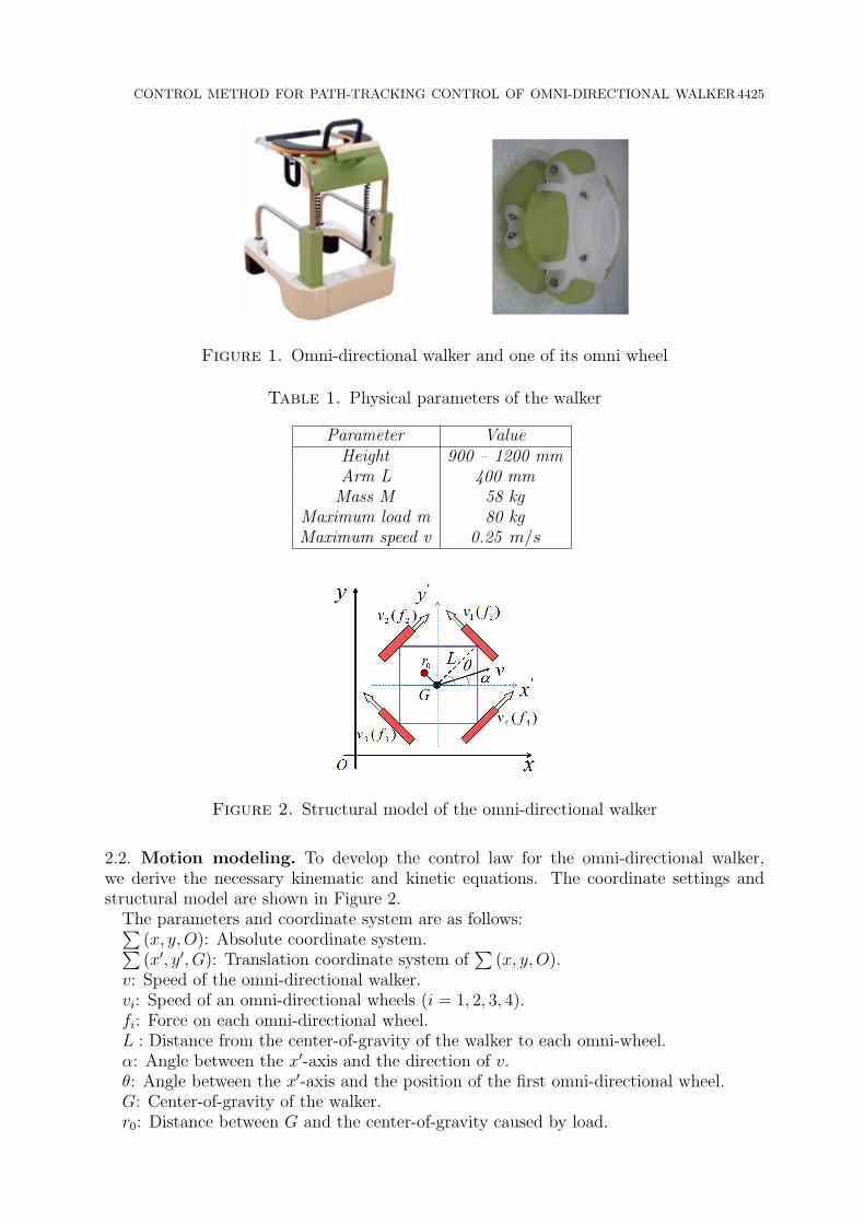
Figure 3. Block diagram of the adaptive control system
Figure 3 shows a block diagram of the control system presented in Theorem 3.1. Theadaptive estimation parameter α obeying adaptive law (6) updates the control law tocontrol the walker.
Remark 3.1. It should be noted that the result in Theorem 3.1 is based on the assumptionthat both M0 is a constant matrix and the system is only slowly time-varying.
4. Simulation. According to the rehabilitation plans designed by physical therapists,the omni-directional walker needs to realize several kinds of movement mainly composedof sequences of linear and rotational movement. Therefore, two simulations to verify theproposed control algorithm are presented in this section. One simulation is of controllingthe walker to follow a linear path, and the other is of controlling the walker to follow acircular path.
4.1. Simulation setting. The physical parameters of the omni-directional walker usedin the simulation are listed in Table 1.The path to be followed is described by
yGd = xGd (10)
Because the initial and final velocities are zero in real walking rehabilitation, we usedthese same values in our simulation trajectory. The trajectory is described by
xGd(t) = d(t) + a
yGd(t) = d(t) + a
θd(t) =π
2
(11)
where
d(t) =
At2− AT
8πsin
(4πtT
) (0 ≤ t < T
4
)−AT
8+ At
(T4≤ t < t0
)−AT
8+ A(t+t0)
2− AT
8πsin
(4πT
(t− t0 +
T4
)) (t0 ≤ t < t0 +
T4
)The physical therapists can change the parameter t0 according to the requirements of
individual users undergoing rehabilitation. The orientation angle is constant in the caseof a linear path. Where A = 0.2 m/s, a = 2 m.In the case of a circular path, a time-variant orientation angle is used. The path to be
followed is described by(xGd − x0)
2 + (yGd − y0)2 = r2 (12)

CONTROL METHOD FOR PATH-TRACKING CONTROL OF OMNI-DIRECTIONAL WALKER4429
where x0 and y0 specify the center of the circle, and r is the radius. In the simulation,values x0 = 4 m, y0 = 4 m and r = 3 m are used. As with the linear path, both initialand final velocities are chosen to be zero. The trajectory is described by
xGd(t) = x0 + r · cos[1
r·(a13t3 +
b12t2)]
yGd(t) = y0 + r · sin[1
r·(a13t3 +
b12t2)]
θd(t) =2π · t142
+π
2
(13)
where a1 = −3.93 × 10⁻⁵ rad·m/s3 and b1 = 5.61 × 10⁻³ rad·m/s2. The parameters a1and b1 can be changed by physical therapists according to the individual requirements ofthe user undergoing rehabilitation.
We simulate the proposed adaptive control algorithm using the kinetics model (3) withdifferent loads and center-of-gravity shifts. The same parameters (λ, K and Γ) for theadaptive controller are applied and adjusted for the case m = 0 kg and r0 = 0.00 m inthe following simulations.
4.2. Simulation results. Figure 4 and Figure 5 show simulations of the proposed adap-tive controller being applied to the tracking of a linear path with initial position xG(0) = 1m, yG(0) = 1 m, and θ(0) = 0.75π rad using the trajectory described in Equation (11).Figure 4 and Figure 5 show simulations for m = 0 kg and r0 = 0.00, and m = 50 kg and r0= 0.20 m, respectively. In Figures 4(a), 4(b), 5(a) and 5(b), the horizontal axes indicate
(a) Tracking performance for x position (b) Tracking performance for y position
(c) Tracking performance for orientation angle θ (d) Tracking and gradient of the walker
Figure 4. Simulation results for linear path with m = 0 kg and r0 = 0.00 m
4430 R. P. TAN, S. Y. WANG, Y. L. JIANG, K. ISHIDA, M. G. FUJIE AND M. NAGANO
(a) Tracking performance for x position (b) Tracking performance for y position
(c) Tracking performance for orientation angle θ (d) Tracking and gradient of the walker
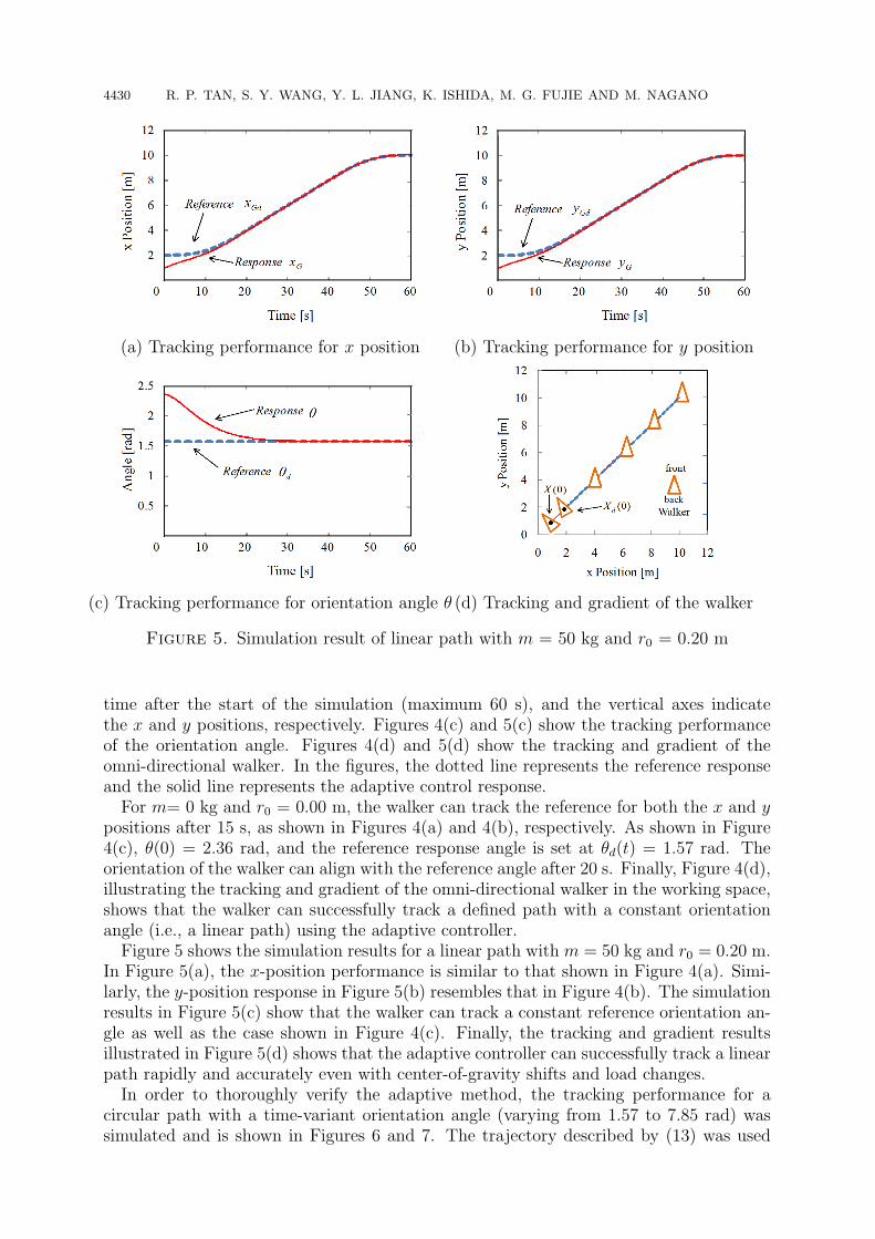
Figure 5. Simulation result of linear path with m = 50 kg and r0 = 0.20 m
time after the start of the simulation (maximum 60 s), and the vertical axes indicatethe x and y positions, respectively. Figures 4(c) and 5(c) show the tracking performanceof the orientation angle. Figures 4(d) and 5(d) show the tracking and gradient of theomni-directional walker. In the figures, the dotted line represents the reference responseand the solid line represents the adaptive control response.For m= 0 kg and r0 = 0.00 m, the walker can track the reference for both the x and y
positions after 15 s, as shown in Figures 4(a) and 4(b), respectively. As shown in Figure4(c), θ(0) = 2.36 rad, and the reference response angle is set at θd(t) = 1.57 rad. Theorientation of the walker can align with the reference angle after 20 s. Finally, Figure 4(d),illustrating the tracking and gradient of the omni-directional walker in the working space,shows that the walker can successfully track a defined path with a constant orientationangle (i.e., a linear path) using the adaptive controller.Figure 5 shows the simulation results for a linear path with m = 50 kg and r0 = 0.20 m.
In Figure 5(a), the x-position performance is similar to that shown in Figure 4(a). Simi-larly, the y-position response in Figure 5(b) resembles that in Figure 4(b). The simulationresults in Figure 5(c) show that the walker can track a constant reference orientation an-gle as well as the case shown in Figure 4(c). Finally, the tracking and gradient resultsillustrated in Figure 5(d) shows that the adaptive controller can successfully track a linearpath rapidly and accurately even with center-of-gravity shifts and load changes.In order to thoroughly verify the adaptive method, the tracking performance for a
circular path with a time-variant orientation angle (varying from 1.57 to 7.85 rad) wassimulated and is shown in Figures 6 and 7. The trajectory described by (13) was used

CONTROL METHOD FOR PATH-TRACKING CONTROL OF OMNI-DIRECTIONAL WALKER4431
(a) Tracking performance for x position (b) Tracking performance for y position
(c) Tracking performance for orientation angle θ (d) Tracking and gradient of the walker
Figure 6. Simulation result of circular path with m = 0 kg and r0 = 0.00 m
with initial positions xG(0) = 6 m, yG(0) = 3 m and θ(0) = 0.75π rad. The referencecurve and adaptive control response are shown for 142 s.
Figure 6 shows simulation results for a circular path withm= 0 kg and r0 = 0.00 m. Thewalker can track the reference target rapidly and accurately for the x position, y position,and time-variant orientation angle θ, as shown in Figures 6(a) – 6(c), respectively. Theresults for tracking and gradient are shown in Figure 6(d).
Figure 7 shows that the tracking performance of the omni-directional walker for acircular path and a time-variant orientation angle with m = 50 kg and r0 = 0.20 m. Theperformance shown in Figures 7(a) – 7(c) is similar to that in Figures 6(a) – 6(c), evenwith the increase in mass from 0 kg to 50 kg and the shift of the center of gravity from0.00 to 0.20 m. In the working space shown in Figure 7(d), both the tracking and gradientare almost identical to those in Figure 6(d).
To evaluate the path-tracking accuracy, path-tracking error E is defined as
E =
∫ xe
xs|yGd − yG| dxG
l(14)
where l is the length of reference path. Equation (14) calculates the area between thereference path and the response path and divides by l. In order to exclude the errorcaused by initial position deviation, the path-tracking error is calculated from 20 s tothe end. The path-tracking error E for a linear path is calculated from xs = xG(20) toxe = xG(60) and circular path from xs = xG(20) to xe = xG(142). The path-trackingerrors of the simulation are shown in Table 2.

4432 R. P. TAN, S. Y. WANG, Y. L. JIANG, K. ISHIDA, M. G. FUJIE AND M. NAGANO
(a) Tracking performance for x position (b) Tracking performance for y position
(c) Tracking performance for orientation angle θ (d) Tracking and gradient of the walker
Figure 7. Simulation result of circular path with m = 50 kg and r0 = 0.20 m
Table 2. Path-tracking errors
Error (m)m = 0 kg, r0 = 0.00 m. m = 50 kg, r0 = 0.20 m.
Linear Path0.009 0.011
xs = xG(20), xe = xG(60)Circular Path
0.008 0.014xs = xG(20), xe = xG(142)
As shown in Table 2, although the load changed from 0 to 50 kg and the center ofgravity shifted from 0 to 0.20 m, the path-tracking error only increased by 0.002 m for alinear path. For a circular path, the path-tracking error only increased by 0.006 m. Thesedata show the effectiveness of the proposed control method relative to that of the PIDcontrol described in [14].Although only linear and circular paths are included in the simulation, the performance
with respect to x position, y position, and orientation angle are all tested. The simulationresults show that the proposed adaptive algorithm is feasible and effective for motioncontrol that takes into consideration center-of-gravity shifts and load changes in the non-linear system of the omni-directional walker. These results also illustrate the advantagesof the omni-wheels, which enable the walker to move in any direction while maintaining itsorientation. Therefore, the omni-directional walker allows a more complex combinationof motions in walking rehabilitation than other walkers.
CONTROL METHOD FOR PATH-TRACKING CONTROL OF OMNI-DIRECTIONAL WALKER4433
The proposed adaptive controller can allow the controlled system converge to the globalminimum point, which is different from the method in [15], which uses a potential functionto avoid the local minima to compensate for the Lyapunov function. PI control with acompensator is effective for constant parameters, as shown in [16]. However, in this paper,the parameters (m or r0) of the controlled system are time-varying, because of variationsintroduced by users, and the proposed adaptive controller can adapt to uncertainties andestimate the system parameter α automatically. Therefore, the method is effective forthis nonlinear system.
Matrix (B) in the proposed adaptive controller is based on the kinetic Equations (4).However, the kinetic equations cannot describe exactly the real walker because the walkeris more complicated. Therefore, in the experiment, it is difficult to get the desired trackingperformance only by adjusting the parameters. A method omitting matrix (B) will beproposed in future work.
5. Conclusions. In this paper, to reduce the error in path tracking of the omni-directionalwalker due to center-of-gravity shifts and load changes, an adaptive control algorithm wasproposed for motion control of the walker. The simulation results demonstrate the effec-tiveness of the proposed algorithm. Therefore, the proposed adaptive control method isapplicable for reducing path-tracking errors, showing its advantages for use in walkingrehabilitation.
Future work will focus on further applying the proposed adaptive control algorithm topath tracking of the walker. Also, a method omitting matrix (B) will be proposed andits effectiveness in dealing with path-tracking errors will be tested in walking training.
Acknowledgment. This work is supported by Grants-in-Aid for Scientific ResearchNos. 20240058 and 21300212 from the Japan Society for the Promotion of Science.
REFERENCES
[1] Y. Nemoto, S. Egawa, A. Koseki, S. Hattori, T. Ishii and M. Fujie, Power-assisted walking supportsystem for elderly, Proc. of the 20th Annual International Conference of IEEE Engineering inMedicine and Biology Society, vol.5, pp.2693-2695, 1998.
[2] K. Kubo, T. Miyoshi and K. Terashima, Influence of lift walker for human walk and suggestionof walker device with power assistance, International Symposium on Micro-NanoMechatronics andHuman Science, Nagoya, Japan, pp.525-528, 2009.
[3] H. Kobayashi, T. Karato and S. Nakayama, Emergence of gait by an active walker, IEEE Interna-tional Conf. on Robotics and Biomimetics, Sanya, China, pp.1035-1040, 2007.
[4] S. Y. Wang, K. Kawata, K. Ishida, H. Yamamoto and T. Kimura, Omni-directional mobile walkerfor rehabilitation of walking, The 17th Society of Life Support Technology, 2001 (in Japanese).
[5] S. Y. Wang, K. Kawata, Y. Inoue, K. Ishida and T. Kimura, Omni-directional mobile walker forrehabilitation of walking which can prevent tipping over, Japan Society of Mechanical EngineersSymposium on Welfare Engineering, vol.39, pp.145-146, 2003.
[6] S. Y. Wang, H. Inoue, K. Kawata, Y. Inoue, M. Nagano, S. Ino, K. Ishida and T. Kimura, Developingthe omni-directional mobile walker and verifying its effect of increase in the muscle power, JSMESymposium on Welfare Engineering, pp.176-177, 2007 (in Japanese).
[7] K. Ishida, S. Y. Wang, T. Nagano and T. Kishi, Development of an all-way mobile walker, J.Physical Medicine, vol.19, no.4, pp.246-250, 2008 (in Japanese).
[8] R. F. Stengel, Optimal Control and Estimation, Dover Publications, Inc., New York, 1994.[9] P. Pannil, K. Tirasesth, P. Ukakimaparn and T. Trisuwannawat, Derivative state constrained opti-
mal H2 control for unstable systems, International Journal of Innovative Computing, Informationand Control, vol.5, no.10(B), pp.3541-3552, 2009.
[10] J. A. Shaw, The PID Control Algorithm, Process Control Solutions, New York, 2003.[11] G. Tao, Adaptive Control Design and Analysis, University of Virginia, Charlottesville, 2003.[12] D. N. Kouya and F. A. Okou, Adaptive backstepping control of a wheeled mobile robot, The 17th
Mediterranean Conf. on Control and Automation, Thessaloniki, pp.85-91, 2009.
4434 R. P. TAN, S. Y. WANG, Y. L. JIANG, K. ISHIDA, M. G. FUJIE AND M. NAGANO
[13] J. J. Slotine and W. Li, Applied Nonlinear Control, Prentice Hall, Mill Valley, 1991.[14] R. P. Tan, S. Y. Wang, Y. L. Jiang, K. Ishida and M. Nagano, Motion control of an omni-directional
walker using adaptive control method, ICIC Express Letters, vol.4, no.6(A), pp.2189-2194, 2010.[15] L. Jiang, M. Deng and A. Inoue, Obstacle avoidance and motion control of a two wheeled mo-
bile robot using SVR technique, International Journal of Innovative Computing, Information andControl, vol.5, no.2, pp.253-262, 2009.
[16] S. Y. Wang, A new omnidirectional wheelchair and its motion control method, ICIC Express Letters,vol.4, no.1, pp.289-294, 2010.