adaptive delay aware error control for internet telephony catherine boutremans jean-yves le boudec...
Post on 21-Dec-2015
225 views
TRANSCRIPT

Adaptive Delay Aware Error Control for Internet
telephonyCatherine BoutremansJean-Yves Le Boudec
IP Telephony Workshop’2001
Institute for computer Communication and Applications
phone: + 41 21 693.5258; fax: +41 21 693.6610
http://icawww.epfl.ch

Framework• Real-time audio over Best Effort networks suffers
from varying packet loss rates, delays and available bandwidth.
• Forward Error Correction (FEC) is an efficient way to recover from packet losses but :– bandwidth requirement
– end-to-end delay
• Adaptive rate/error control was proposed but it does not try to optimize the end-to-end delay

Motivation
• Above a certain threshold (around 150ms): the end-to-end delay is annoying
• New differentiated services, such as Alternative Best Effort offer applications the trade-off between receiving lower end-to-end delay (and higher loss rates) or more overall throughput.
important to take the end-to-end delay into account in the adaptive control scheme

Adaptive Delay aware error control
• Problem definition:
develop an error control scheme for audio which is delay aware (namely, which chooses the FEC according to its impact on the end-to-end delay) for Best Effort Internet services such as:
1) Flat 2) ABE
• Out of scope:validation of perceptual models

Outline• A.Our Joint rate/error/delay control scheme
– 1. Error recovery taken from media specific FEC – 2. An RTCP-based Rate control scheme– 3. A new Delay control scheme – 4. Our Global optimization problem
• B.Simulation examples– 1. Flat Network: what do we improve?– 2. ABE: Is it worth to be green?

Dr
Rr
Dr
Rr
1.How media specific FEC Works
Qmax
Rmax
Qmax
Rmax
Audio Frame 3Audio Frame 4
primary/source encoding
Dp
Rp
Dp
Rprate
Qua
lity
... ... packet stream345
• Start with high rate audio encoding
234
• copy audio, compress, and delay
secondary/redundancy encoding35 4 reconstruction
• if packet lost, recover from redundancy

1.Efficiency of FEC mainly depends on packet loss
process• Loss process of audio packets in the Internet
can be modeled as low order Markov chain
• In this work: Gilbert Model
10
p
1-q1-p
q
qp
pPLR
qp
qp n
1)1(
)losses econsecutivProb(n

2.Our RTCP-based Rate Control scheme
• Audio streams have to share bandwidth fairly with TCP connections TCP-Friendly
• Equation-Based TCP Friendly rate control (Padhye):
• Rate controlled via packet size (constant packet intervals)
• Use RTCP for Feedback• EWMA filter of PLR in order to smooth the rate
)321()8
33(
32
_
2plrplrplr
tplr
RTT
sizepcktR
RTO
TCP

2. Our Rate control achieves fairness
0 50 100 1500
0.2
0.4
0.6
0.8
1
1.2
1.433.33% TFRC vs 66.66% Sack TCP, 5Mb/s, RED Queuing
Number of connections (TCP + TFRC)
No
rma
lize
d th
rou
gh
pu
t
TCP FriendTCP
Our scheme shares bandwidth fairly withTCP connections
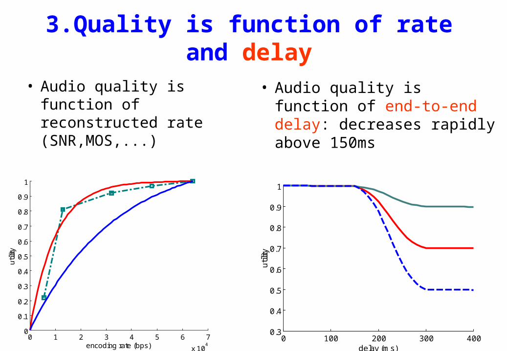
3.Quality is function of rate and delay
• Audio quality is function of reconstructed rate (SNR,MOS,...)
• Audio quality is function of end-to-end delay: decreases rapidly above 150ms
0 50 100 150 200 250 300 350 4000.75
0.8
0.85
0.9
0.95
1
delay (ms)
utili
ty
0 1 2 3 4 5 6 7
x 104
0
0.1
0.2
0.3
0.4
0.5
0.6
0.7
0.8
0.9
1
encoding rate (bps)
util
ity
0 50 100 150 200 250 300 350 4000.65
0.7
0.75
0.8
0.85
0.9
0.95
1
delay (ms)
util
ity
0 1 2 3 4 5 6 7
x 104
0
0.1
0.2
0.3
0.4
0.5
0.6
0.7
0.8
0.9
1
encoding rate (bps)
util
ity
0 100 200 300 4000.3
0.4
0.5
0.6
0.7
0.8
0.9
1
delay (ms)
util
ity

3.Quality is function of rate and delay
• Consider the user perceived quality (utility) as a function of the reconstructed rate (R) and the overall end-to-end delay (D)
• We use several utility curves as we don’t know which one is the best.

4.Our Joint rate/error/delay control
• A source with flexibility to encode audio at rate• Unreliable network characterized by
– a loss distribution Gilbert Model : r.v.– a delay distribution – an available bandwidth TCP-Friendly rate constraint
• A utility function of delay and reconstructed rate
kbpsx 64,0
),( DRf
Consider:
1,0iX

4.Our Joint rate/error/delay control
Constrained optimization problem:
Define:• K = of copies of audio segment sent over the network• ,the delay spent on FEC• the r.v. the set of copies that make it across the
network KiXi i ,...,1,0
valpckt_interKK )1(
),(max
Ωx,K i
Knetworkii1,..,K1,...,K)(inbmax1
DxfΡ(Ω)maximize
Under TCPoverhead
K
ii RRx
1
Ki0xi ,...,1, MAXtionreconstrucafter PLRPLR

• General solution is derived using Lagrange Multipliers for small values of K and via numerical method SQP for K4
• The solution has the following properties:– – if (p+q)1 it pays to offset and to put more quality into the
end packets– if (p+q)1 better not to offset and
4.Our Joint rate/error/delay control
Solution:
2,...,Kixx i ,1
Kxxx ...21

B.Simulation examples• Single bottleneck
• Topology with small and long flows
• Bottleneck BW = 15Mbps, 5Mbps
• variable number of connections
d1 d1 d2d2

Example 1: when delay is important
0 20 40 60 80 100 1200.3
0.4
0.5
0.6
0.7
0.8
0.9
1Utility 3 ,5Mbits/s,d
prop=100ms
Number of flows
Util
ity
K = 1 K = 2 K = 3 K = 4 K = 5 Delay-Aware
0 20 40 60 80 100 1200.1
0.12
0.14
0.16
0.18
0.2
0.2299% percentile e2e delay ,5Mbits/s,d
prop=100ms
Number of flows
De
lay
(s)
K = 1 K = 2 K = 3 K = 4 K = 5 Delay-Aware
0 20 40 60 80 100 1200
0.02
0.04
0.06
0.08
0.1
0.12
0.14
0.16
Packet loss rate,5Mbits/s,dprop
=100ms
Number of flows0 20 40 60 80 100 120
0
50
100
150
200
250
300
350
400
450TCP-Friendly Rate ,5Mbits/s,d
prop=100ms
Ra
te (
Kb
its/s
)
Number of flows

Example 2: when delay is not important
0 20 40 60 80 100 1200.55
0.6
0.65
0.7
0.75
0.8
0.85
0.9
0.95
Utility 1 ,5Mbits/s,dprop
=100ms
Number of flows
Util
ity
K = 1 K = 2 K = 3 K = 4 K = 5 Delay-Aware
0 20 40 60 80 100 1200.1
0.12
0.14
0.16
0.18
0.2
0.2299% percentile e2e delay ,5Mbits/s,d
prop=100ms
Number of flows
De
lay
(s)
K = 1 K = 2 K = 3 K = 4 K = 5 Delay-Aware
0 20 40 60 80 100 1200
0.02
0.04
0.06
0.08
0.1
0.12
0.14
0.16
Packet loss rate,5Mbits/s,dprop
=100ms
Number of flows0 20 40 60 80 100 120
0
50
100
150
200
250
300
350
400
450TCP-Friendly Rate ,5Mbits/s,d
prop=100ms
Ra
te (
Kb
its/s
)
Number of flows

0 20 40 60 80 100 1200.65
0.7
0.75
0.8
0.85
0.9
0.95
1Utility 2 ,5Mbits/s,d
prop=100ms
Number of flows
Util
ity
K = 1 K = 2 K = 3 K = 4 K = 5 Delay-Aware
0 20 40 60 80 100 1200.1
0.12
0.14
0.16
0.18
0.2
0.2299% percentile e2e delay ,5Mbits/s,d
prop=100ms
Number of flows
De
lay
(s)
K = 1 K = 2 K = 3 K = 4 K = 5 Delay-Aware
Example 3: tradeoff between delay and audio distortion
0 20 40 60 80 100 1200
0.02
0.04
0.06
0.08
0.1
0.12
0.14
0.16
Packet loss rate,5Mbits/s,dprop
=100ms
Number of flows0 20 40 60 80 100 120
0
50
100
150
200
250
300
350
400
450TCP-Friendly Rate ,5Mbits/s,d
prop=100ms
Ra
te (
Kb
its/s
)
Number of flows

1. FLAT: Conclusion
• The Delay aware scheme increases utility by avoiding that the source waste delay on the FEC when it is not really needed.

2.ABE: Alternative Best Effort
• ABE is a novel service for IP networks which offers the choice between receiving a lower end-to-end delay or more overall throughput.
• Packets are marked either green or blue.• Green packets receive a low, bounded queuing
delay but they receive more losses during bouts of congestion.
• Blue packets receive more throughput (and less losses) but also more delay jitter.

Is it worth being green?
• Green packets receive a lower delay but they experience more losses (and hence, receive less throughput).
• Losses are repaired using FEC but FEC increases the e2e delay and the BW requirement.

• With small RTT, difference is minor.
0 50 1000.05
0.1
0.15
0.2
0.25
Packet loss rate
0 50 100
0.9
0.95
1Utility
Load in network
Blue Green
0 50 1000.04
0.06
0.08
0.1
0.12
0.1499% percentile e2e delay
Load in network
De
lay (
s)
0 50 1000.5
1
1.5
2
2.5x 10
5 TCP-Friendly Rate
Ra
te (
b/s
)

• Higher RTT (2 bottlenecks): green is better if load not too high.
10 20 30 400.1
0.15
0.2
0.25
0.3Packet loss rate
10 20 30 400.5
0.6
0.7
0.8
0.9
1Utility
Load in network
Blue Green
10 20 30 400.05
0.1
0.15
0.2
0.2599% percentile e2e delay
Load in network
De
lay
(s
)
10 20 30 402
4
6
8
10
12x 10
4 TCP-Friendly Rate
Ra
te (
b/s
)

• Higher RTT (1 bottleneck): green always better
0 50 1000
0.05
0.1
0.15
0.2Packet loss rate
0 50 1000.75
0.8
0.85
0.9
0.95
1Utility
Load in network
Blue Green
0 50 1000.1
0.12
0.14
0.16
0.18
0.299% percentile e2e delay
Load in network
De
lay
(s
)
0 50 1000.5
1
1.5
2
2.5x 10
5 TCP-Friendly Rate
Ra
te (
b/s
)

2. ABE: Conclusions
• It is worth accepting to receive less bandwidth (and more losses) except in trivial cases where– the RTT is small anyway– the network is badly congested
• Need for adaptive Color choosing algorithms
Conclusions
• We proposed an adaptive Delay aware error control scheme.
• We showed it could prevent a source from wasting delay on FEC when not necessary.
• It helped us to figure out that it was worth trading throughput for delay.