adaptive hardware infrastractures for sapmedia.techtarget.com/searchsap/downloads/adaptive... ·...
TRANSCRIPT

Mißbach, Gibbels, Karnstädt, Stelzel, Wagenblast
Adaptive Hardware Infrastructures for SAP®

5Contents
Contents
Foreword 13
Foreword 15
Introduction 17
1 SAP NetWeaver 23
1.1 The SAP Product Portfolio .............................................................................. 24
1.2 The Components of SAP NetWeaver ............................................................ 26
1.3 SAP Enterprise Portal ...................................................................................... 27
1.4 SAP Mobile Infrastructure .............................................................................. 32
1.5 SAP Business Intelligence ............................................................................... 34
1.6 SAP Knowledge Warehouse ........................................................................... 40
1.7 SAP Master Data Management ..................................................................... 42
1.8 SAP Exchange Infrastructure .......................................................................... 45
1.9 SAP NetWeaver Development Environment ............................................... 50
1.10 SAP Solution Manager .................................................................................... 54
1.11 User and Authorization Management .......................................................... 57
1.12 Summary ............................................................................................................ 59
2 mySAP Business Applications 61
2.1 mySAP ERP ........................................................................................................ 622.1.1 mySAP Financials ............................................................................... 642.1.2 mySAP Operations ............................................................................ 652.1.3 mySAP Human Capital Management .............................................. 672.1.4 mySAP Analytics ................................................................................ 682.1.5 mySAP Corporate Services ............................................................... 692.1.6 Additional mySAP ERP Components .............................................. 70
2.2 Industry Solutions ............................................................................................ 71
2.3 mySAP Customer Relationship Management ............................................. 722.3.1 mySAP CRM Interaction Center ...................................................... 742.3.2 SAP Internet Sales ............................................................................. 75

Contents6
2.4 mySAP Supply Chain Management ............................................................... 792.4.1 SAP Advanced Planner and Optimizer (APO) ................................ 802.4.2 SAP Event Management ................................................................... 822.4.3 SAP Inventory Collaboration Hub ................................................... 84
2.5 mySAP Supplier Relationship Management ................................................ 85
2.6 mySAP Product Lifecycle Management ........................................................ 872.6.1 Product Development and Product Launch ................................... 872.6.2 Asset and Buildings Management .................................................... 892.6.3 Quality Management ........................................................................ 892.6.4 Hazardous Substance Management, Industrial Hygiene and
Safety, Environmental Protection .................................................... 90
2.7 An Example of SAP xApps: SAP Global Trade Services .............................. 91
2.8 Solutions for Small and Midsize Enterprises ............................................... 92
2.9 Summary ............................................................................................................ 92
3 SAP Web Application Server 95
3.1 The Classic SAP Architecture .......................................................................... 96
3.2 The Anatomy of the Web AS .......................................................................... 973.2.1 ABAP Engine ....................................................................................... 983.2.2 J2EE Engine ........................................................................................ 993.2.3 Buffer ................................................................................................... 1033.2.4 Database Layer ................................................................................... 1033.2.5 SAP Internet Communication Manager .......................................... 1043.2.6 Internet Graphics Service .................................................................. 1053.2.7 The Achilles’ Heel of an SAP System ............................................... 105
3.3 Internationalization .......................................................................................... 1063.3.1 Unicode ............................................................................................... 1083.3.2 SAP and Unicode ............................................................................... 109
3.4 SAP System Landscapes .................................................................................. 111
3.5 Grid Computing ................................................................................................ 115
3.6 Summary ............................................................................................................ 117
4 System Dimensioning and Service Level Agreements 119
4.1 The Meaning of Service Level Agreements .................................................. 120
4.2 User-Based Sizing ............................................................................................. 123
4.3 Transaction-Based Sizing ................................................................................ 124
4.4 The Limits of the Sizing Process .................................................................... 127
4.5 Response Time .................................................................................................. 129
4.6 Main Memory Requirement ........................................................................... 132
4.7 Hard Disk Capacity .......................................................................................... 135

7Contents
4.8 Units of Measure for Application Load and System Throughput ............ 136
4.9 Sizing SAP NetWeaver Systems ..................................................................... 1384.9.1 Enterprise Portal ................................................................................ 1394.9.2 Mobile Infrastructure ........................................................................ 1394.9.3 Business Information Warehouse .................................................... 1394.9.4 Exchange Infrastructure .................................................................... 1424.9.5 Master Data Management ................................................................ 143
4.10 Sizing mySAP Solutions .................................................................................. 1434.10.1 Customer Relationship Management .............................................. 1434.10.2 Supply Chain Management .............................................................. 1444.10.3 Supplier Relationship Management ................................................ 1464.10.4 Product Lifecycle Management ....................................................... 147
4.11 Deciding on the Server Configuration .......................................................... 147
4.12 Guaranteed Performance? .............................................................................. 150
4.13 How Reliable Is Sizing? ................................................................................... 152
4.14 Summary ............................................................................................................ 157
5 SAP System Platforms 159
5.1 Computer Technologies for mySAP .............................................................. 160
5.2 Processor Architectures .................................................................................. 161
5.3 Main Memory Architectures .......................................................................... 165
5.4 Error-Tolerant Memory ................................................................................... 167
5.5 The System Bus ................................................................................................ 168
5.6 I/O Architectures .............................................................................................. 171
5.7 Blade Servers ..................................................................................................... 172
5.8 Operating Systems for mySAP ....................................................................... 173
5.9 Databases for mySAP ...................................................................................... 179
5.10 System Performance and Scalability ............................................................. 180
5.11 Memory Addressing ........................................................................................ 183
5.12 Summary ............................................................................................................ 187
6 Data Storage for SAP Systems 189
6.1 The “Files” of an SAP System ......................................................................... 189
6.2 Read/Write Accesses from the Application Perspective ........................... 193
6.3 Read/Write Performance from the Physical Perspective ........................... 194
6.4 Availability from a Data Perspective ............................................................. 196
6.5 File Systems ...................................................................................................... 203
6.6 Disk Array Caches ............................................................................................ 204
6.7 Data Replication ............................................................................................... 206

Contents8
6.8 Connection Technologies for Disk Subsystems .......................................... 208
6.9 Sizing Storage Subsystems ............................................................................. 214
6.10 Structuring Storage Subsystems .................................................................... 220
6.11 The Other SAP Servers .................................................................................... 228
6.12 Consolidating Storage Subsystems ............................................................... 230
6.13 Data Archiving .................................................................................................. 231
6.14 Summary ............................................................................................................ 234
7 High Availability SAP Systems 235
7.1 Downtimes ........................................................................................................ 236
7.2 What Is Availability? ........................................................................................ 237
7.3 What Level of Availability Is Required? ........................................................ 238
7.4 How Much Performance Is Necessary in an Emergency? .......................... 240
7.5 What Level of Stability Is Required? ............................................................. 241
7.6 Avoiding Downtime ......................................................................................... 243
7.7 Components of High Availability ................................................................... 244
7.8 The Proper Environment ................................................................................. 246
7.9 Hardware Infrastructure .................................................................................. 248
7.10 Operating Systems ........................................................................................... 251
7.11 Failover Systems ............................................................................................... 254
7.12 SAP Cluster Configurations ............................................................................ 259
7.13 Cluster Consistency ......................................................................................... 266
7.14 Data Backup ...................................................................................................... 270
7.15 Backup/Restore and Recovery ........................................................................ 274
7.16 Application ........................................................................................................ 282
7.17 System Operation ............................................................................................. 285
7.18 Summary ............................................................................................................ 286
8 Presentation Layer and Output Management 289
8.1 Frontend—The User Interface ........................................................................ 289
8.2 The Future—Web Dynpro ............................................................................... 293
8.3 Mobilization—Online and Offline ................................................................. 297
8.4 Output for mySAP ............................................................................................ 2988.4.1 Spool Management ........................................................................... 2998.4.2 Form Management ............................................................................ 3018.4.3 Output Management ........................................................................ 306
8.5 Summary ............................................................................................................ 309
9Contents
9 Network Requirements for SAP 311
9.1 The Influence of the Network on Performance ........................................... 312
9.2 Network Influence on Costs ........................................................................... 3189.2.1 Bandwidth for SAP Servers ............................................................... 3199.2.2 Bandwidth for SAP Users .................................................................. 320
9.3 Network Load Caused by Different SAP Applications ............................... 3239.3.1 SAP Business Information Warehouse 4.0 ..................................... 3249.3.2 SAP Advanced Planner & Optimizer ............................................... 3259.3.3 mySAP Customer Relationship Management 4.0 ......................... 325
9.4 Estimating the Required Bandwidth ............................................................ 3279.4.1 Bandwidth for the User Connection ............................................... 3289.4.2 Bandwidth for Print and Other Output .......................................... 3299.4.3 Other Network Loads ....................................................................... 3329.4.4 Practical Example ............................................................................... 334
9.5 Network Influence on Availability ................................................................. 336
9.6 Summary ............................................................................................................ 338
10 Logical Network Architectures and Network Security 341
10.1 Logical Network Structures ............................................................................ 34210.1.1 IP Address Concepts ......................................................................... 34210.1.2 Name and Address Resolution ........................................................ 34410.1.3 Name Resolution Methods .............................................................. 34710.1.4 SAP Servers with Several Network Cards ....................................... 34910.1.5 Identifying the SAP Data Traffic ....................................................... 351
10.2 Load Balancing and Availability ..................................................................... 352
10.3 Security Aspects ............................................................................................... 35810.3.1 User Authentication .......................................................................... 35810.3.2 Demilitarized Zones .......................................................................... 361
10.4 Summary ............................................................................................................ 365
11 Local Area Network Solutions 367
11.1 High Availability for Local Networks ............................................................ 36811.1.1 Link Aggregation ................................................................................ 37111.1.2 Highly Available Network Clusters for Business-critical
Applications ........................................................................................ 37111.1.3 Error-tolerant Meshed Networks .................................................... 373
11.2 Wires and Fibers .............................................................................................. 37511.2.1 Copper Cables .................................................................................... 37511.2.2 Fiber Optics Cables ........................................................................... 37711.2.3 Installation Guidelines for Cable Networks ................................... 380

Contents10
11.3 Potential Equalization, Grounding, and Lightning Protection ................. 381
11.4 Wireless Networks ........................................................................................... 38311.4.1 WLAN Standards ............................................................................... 38311.4.2 Installation Guidelines for Wireless Networks ............................... 38711.4.3 Ad-Hoc Networks .............................................................................. 39111.4.4 Mobile Communications .................................................................. 392
11.5 Voice—Data Convergence .............................................................................. 392
11.6 Summary ............................................................................................................ 393
12 WAN and Web Connections 395
12.1 WAN Technologies ........................................................................................... 39712.1.1 Leased Lines ....................................................................................... 39712.1.2 ISDN .................................................................................................... 39712.1.3 DSL ...................................................................................................... 39812.1.4 X.25 ..................................................................................................... 39912.1.5 Frame Relay ........................................................................................ 39912.1.6 ATM ..................................................................................................... 40012.1.7 Internet ............................................................................................... 40112.1.8 Multiprotocol Label Switching ......................................................... 40212.1.9 Satellite Connections ......................................................................... 404
12.2 Strategies for Cost Optimization ................................................................... 40512.2.1 Filtering, Spoofing, and Compression ............................................. 40612.2.2 Bandwidth on Demand ..................................................................... 40712.2.3 Data Prioritizing ................................................................................. 408
12.3 Security Aspects of WAN Communication .................................................. 409
12.4 Failure-Tolerant WAN Connections .............................................................. 41112.4.1 Redundant Hardware ........................................................................ 41212.4.2 Redundant Connections ................................................................... 412
12.5 Summary ............................................................................................................ 415
13 Adaptive Infrastructures 417
13.1 Reasons for Adaptive Infrastructures ........................................................... 417
13.2 Virtualization of Hardware .............................................................................. 420
13.3 SAP Adaptive Computing ............................................................................... 427
13.4 Storage in the Adaptive Computing Concept ............................................. 431
13.5 Software Logistics ............................................................................................ 43213.5.1 Provisioning of Operating Systems .................................................. 43213.5.2 Installing Application Services .......................................................... 43313.5.3 Printing in Adaptive Infrastructures ................................................. 43713.5.4 Availability and Adaptive Computing .............................................. 437
13.6 Adaptive Application Scenarios ..................................................................... 439
13.7 Summary ............................................................................................................ 449

11Contents
14 IT Service and Application Management 451
14.1 IT Service Management Reference Model ................................................... 454
14.2 Enterprise System Management ................................................................... 462
14.3 Business Process Management ...................................................................... 474
14.4 Example of a Typical Application Scenario .................................................. 478
14.5 Summary ............................................................................................................ 488
15 SAP Operating Costs 489
15.1 The Benefits of IT ............................................................................................. 490
15.2 IT Cost Structures ............................................................................................ 490
15.3 Cost-Efficiency Analyses ................................................................................. 49415.3.1 Classic Investment Calculation ........................................................ 49515.3.2 Return on investment ....................................................................... 49615.3.3 Total Cost of Ownership ................................................................... 49715.3.4 Other Tools ........................................................................................ 502
15.4 Reducing TCO by Consolidation ................................................................... 50415.4.1 Technical Consolidation .................................................................... 50615.4.2 SAP System Consolidation ................................................................ 50815.4.3 Application Consolidation ................................................................ 510
15.5 Reducing TCO by Platform Migration .......................................................... 510
15.6 Summary ............................................................................................................ 516
Sources and Further Reading 519
The Authors 521
Index 523

13Foreword
Foreword
In safeguarding their competitiveness, many companies today face thechallenge of having to constantly adapt their business processes to theever-changing requirements of the market. The main issues that compa-nies must address are the increasing internationalization of markets andproduction locations, the creation of new partner networks (due todecreasing vertical integration within companies, for example), and thetimely introduction of new products and services.
With the continuing development of its software solutions—from R/2and R/3 to the multi-tier, Internet-enabled architecture of the mySAPBusiness Suite—SAP makes a significant contribution to helping compa-nies meet this challenge. In particular, SAP’s latest measure, in which itbrought together its existing solutions in a Web-based services architec-ture, was intended to address the aforementioned needs for adaptation.This new architecture enabled the combining of individual function mod-ules (for example, a module for creating a customer order) in order to cre-ate new solution modules and therefore support changing business pro-cesses quickly and cost-effectively while maintaining high quality.
Today, IT managers in most companies are faced daily with the questionof how to reconcile the need for cost-cutting in the implementation andoperation of SAP solutions with the demand to make these solutionsmore flexible. The most frequently asked questions are:
� What significance do the changing SAP solution architectures have forunderlying IT infrastructures?
� What does an SAP IT infrastructure have to do in order to be able toadapt quickly to changing requirements?
� How do we ensure that issues such as high availability, performance,and scalability are not neglected?
� What can we expect from operating these ‘adaptive SAP solutions’ interms of their running costs?
This book provides real-world answers to these questions. The team ofauthors, under the leadership of Dr. Michael Mißbach, Senior Consultantat Hewlett-Packard (HP), has several years’ combined experience dealingon a daily basis with international clients and various SAP developmentand consulting departments in solving similar questions. His wealth ofexperience is reflected in this book, which focuses on current develop-ments in platform and network technologies, and on technologies and

Foreword14
concepts for operations optimization such as virtualization, IT ServiceManagement (ITSM), and Total Cost of Ownership (TCO).
Moreover, this book highlights the close cooperation that has existedbetween SAP and HP for 15 years now, both in various technologicaldevelopments and the daily joint support of thousands of clients world-wide.
Dr. Wolfgang OskierskiSAP Business Manager EMEA
15Foreword
Foreword
The argument for using IT to support enterprise processes is stronger thanever today.
While managers in enterprises usually have little or no understanding ofthe concepts and specifics of information technology, they will still artic-ulate what they expect from IT: to provide a measurable business value.However, they do so in their own specific “business-language“ vernacular.The ability to translate these expectations expressed in business-speakinto IT requirements is an art in itself; however, it is one that we mustmaster if we want to position technology in its rightful place in our enter-prises.
A situation where employees have to spend an indefinite amount of timein front of a static input screen to search for the information they require(and possibly never find it) is not the way to demonstrate the efficiencythat is always demanded of IT in day-to-day business operations. A farbetter way to show the usefulness and value of IT is to have the interfaceopen up a communications portal that can adapt itself to very specificindividual requirements. SAP refers to it as a “role-based user interface“and it is considered to be a result of an Enterprise Services Architecture(ESA). This kind of architecture clearly demonstrates the value proposi-tion of IT, because it enables users to access the information they requirequickly and directly.
That’s the theory.
For this kind of application layer to be feasible in the real world, a stableand solid basis is a must. SAP has its own name for this too—SAPNetWeaver—which is the foundation of the ESA structure. SAPNetWeaver forms a basis that consolidates and provides informationabout the people, information, and processes in an enterprise. Only if thebasis is strong enough does the added value of the overlying applicationand communication landscape become apparent. An added difficulty isthat besides being solid, the basis must be also highly flexible—two fac-tors that may initially appear to be mutually exclusive.
In business-speak, this means that in the coming years we’ll see anincreased demand for solutions that promise quick interchangeability andease of integration into existing landscapes. Shorter roll-out times andlower process costs will be expected as well, and the demand for contri-

Foreword16
butions from IT solutions to value creation and the fulfillment of enter-prise strategies will be, in a word, uncompromising.
This book is intended to help you lay the foundation for successful pro-cess design and visible added value in your enterprise. It will assist you inmapping out your own strategic path, along which enterprise visions canbecome a reality. Economizing in the wrong places in this context simplyprovides fertile ground for risks and errors rather than value creation, andthis book thus makes a significant contribution to the success of ESAstrategies.
May you have many hours of enjoyment reading this book and may youhave success in creating solid solutions that bridge the gap between ITand business.
Andreas Kerbusk
Chairman of the German SAP User Group (DSAG e.V.)

17
Introduction
Adaptive IT infrastructures for agile enterprises
While most IT projects in recent years have been dominated by the needto cut costs, today enterprises are enhancing their competitiveness byusing IT to adapt their business processes to markets that are changingevermore rapidly.
This is because thinking purely in terms of costs makes sense only up to apoint. Without any doubt the cheapest IT system is the one which is com-pletely written of and is running without any change, however continu-ally changing market conditions mean that enterprises are forced to mod-ify their processes, including their IT, on an ongoing basis. Therefore,enterprises have a clear competitive advantage if their IT is flexibleenough to be able to implement new processes quickly.
However, it is not just the markets that are changing. Company mergersand acquisitions indicate that enterprises themselves are becomingincreasingly agile. For example, steel companies can turn into mobiletelephone operators or tourism enterprises, and it is not always the bigfish that swallow the small fish. In these cases, too, it is the speed atwhich the IT infrastructure can be adapted to the new circumstances thatdetermines the success or failure of an enterprise.
SAP NetWeaver and ESA
With SAP NetWeaver, and especially the Enterprise Services Architecture,SAP has developed products and concepts that will have a dramatic effecton how IT is used to benefit enterprises. These concepts form the basisfor quickly introducing and adapting business processes. However, forthis to be possible, enterprises need an infrastructure that is as adaptiveas the software, while still providing a stable technology basis.
Technologies for adaptive infrastructures are not a completely new con-cept. For some time, many hardware manufacturers have been workingon consolidation concepts that include the “virtualization” of server andstorage resources.
SAP Adaptive Computing Controller
One new concept, however, is the idea of incorporating the application,which creates an holistic, all-around solution. With the introduction ofSAP Adaptive Computing, this kind of solution is beginning to make itsmark. For the first time, the SAP Adaptive Computing Controller providesan interface between the infrastructure and the application, and there-

Introduction18
fore implements the preliminary steps toward integrating two previouslyseparate worlds.
Availability The increasing predominance of SAP solutions in enterprise processesproves that enterprises are becoming increasingly more dependent onthese systems. High availability is therefore gaining more importance thanever before. Because business processes in SAP NetWeaver environmentsare distributed across several SAP systems, the processes can work only ifevery system is functioning perfectly. Similarly, Enterprise Services Archi-tectures (ESA), which can integrate functionalities from different systemsin an overlying business process in a very short space of time, can workonly if all the connected systems are equally available.
However, high availability does not depend on technology alone. Besidesunified management and monitoring tools, running adaptive infrastruc-tures also requires the consistent and carefully planned use of IT ServiceManagement (ITSM) methods.
Adaptivity After many discussions with customers, the authors have learned thatthere is a demand for a guide to adaptive infrastructures. However, every-one has his or her own idea about the meaning of “adaptive“—from sim-ple load distribution mechanisms to the virtualization of whole data cen-ters or automatic recognition and monitoring of resources. Intrinsic to alldefinitions is the goal of enabling infrastructures to adapt flexibly to busi-ness requirements. This book provides an outline of all the aforemen-tioned topics.
The great demand for our two existing books, which deal with the infra-structure and the operation of SAP systems, encouraged the authors toproduce this third book, which deals with the latest developments andchallenges and their corresponding solutions. We also outline trends forthe future, where appropriate. Therefore, this book is an addition to thebooks we previously authored, and not simply an update.
To ensure that readers who do not regard themselves as “gurus“ in eacharea can still derive benefit from reading this book, the most importanttechnologies are explained in detail. Practice-oriented guidelines are pro-vided throughout the book in order to make the reader aware of essentialbut often less obvious facts. The book concentrates exclusively on thetechnical aspects of IT infrastructure; the details of how to install andadapt SAP software to business processes are beyond the scope of thisbook.

19
The solutions presented here refer to the latest releases at the time ofprinting. However, although the laboratories are constantly producingnew hardware and software, the underlying technologies and architec-tures change much more slowly, and so the concepts presented here canbe used on a long-term basis. Also, many of the technical solutions pre-sented here are also suitable for other enterprise-critical software sys-tems.
The book has intentionally taken a neutral stance in terms of manufactur-ers. Nonetheless, the authors are employees of the SAP HP InternationalCompetence Center and their expertise is largely based on the numeroussolutions that have been developed there since 1989. For this reason,SAP and HP products, and solutions from partner companies, of whichthe authors have positive experiences, are used as examples for a class ofsolutions. However, references to any product do not represent an eval-uation of that product.
Structure of the Book
Each chapter of this book contains a short introduction that outlines thegoals of that particular chapter. Wherever possible, the detailed descrip-tions of the solutions are addressed in terms of performance, availability,and flexibility, and are illustrated by real-world examples. The closing sec-tion of each chapter consists of a short summary of the main recommen-dations.
The first two chapters provide a brief description of the functionalities ofthe SAP software components and of the underlying technical compo-nents involved in each case from an IT point of view to establish the foun-dation for the subsequent chapters. Chapter 1 gives an overview of thefunctionality and use of the SAP NetWeaver components. It alsodescribes the software lifecycle of the SAP solution and user managementsolutions.
Chapter 2 presents the solutions of the mySAP Business Suite and placesthem in the context of the Enterprise Services Architecture.
Chapter 3 introduces the architecture of the SAP Web Application Server,which is a platform for the process execution of almost all SAP solutions.In doing so, it deals with the ABAP and the Java stack and considers thevarious aspects of Unicode implementation. Lastly, it looks at aspects ofgrid computing.

Introduction20
Chapter 4 deals with dimensioning computer systems. The focus here ison explaining the most important parameters used for designing a hard-ware landscape. This chapter ends with an examination of the level ofexactness that can be achieved with a standard approach to sizing.
Chapter 5 presents computer systems for SAP applications. It describesthe available technologies with particular emphasis on the design of theprocessor and main memory, and describes the advantages and disadvan-tages of blade concepts. It also presents the various operating systems,with a special focus on Linux.
Chapter 6 deals with the disk storage sub-systems of the SAP databaseserver. It describes the various files in an SAP system and explains how todimension and structure storage sub-systems. It also deals with how Net-work Attached Storage (NAS) can be used with SAP.
Chapter 7 tackles the subjects of availability and downtime in integratedsystems of mission critical systems. All aspects of high availability are pre-sented here, from protecting a computer center from disasters, to clustertechnologies and shadow databases, to system operation.
Chapter 8 describes the various user interfaces of the SAP solutions, aswell as print and output management solutions. It also presents the newInteractive Forms and SAP Web Dynpro.
Chapters 9 to 12 deal with network infrastructures for SAP system land-scapes. The specific requirements that an SAP system has in terms of net-work bandwidth and latency, as well as the specific aspects of local-areaand wide-area networks are each dealt with in their own separate chap-ters. Another chapter deals with protecting enterprise data and systemsfrom unauthorized access via the Internet.
Chapter 13 shows how the virtualization technologies presented in theprevious chapters can be used to build flexible SAP infrastructures. It alsodescribes the SAP Adaptive Computing Controller and 10 different appli-cation scenarios for adaptive infrastructures.
Chapter 14 addresses the management of Enterprise Services Architec-tures. It also presents the IT Service Management (ITSM) reference modeland the various management system concepts for monitoring, analyzing,and optimizing the infrastructure. An example of a vendor-managedinventory scenario illustrates the various points.
Chapter 15 explores the cost aspects of operating an SAP system. Itbriefly describes the most common scientific models and a model for

21
structuring the overall operating costs. Lastly, using two practical exam-ples, it discusses the costs and benefits of a system integration scenario,and compares the operating costs of a scale-up concept with those of ascale-out concept.
Acknowledgements
This book is the product of voluntary work done in our free time duringmany nights and weekends. We therefore dedicate it to our wives andchildren, who have had to spend a lot of time without our undividedattention.
We would also like to thank all the customers and colleagues who self-lessly provided much help in the form of tips, contributions, and con-structive criticism. Without their support, we would not have been ableto write this book. In particular, we would like to mention Helmut Fieres,Sebastian Buhlinger, Marina Marscheider, Roland Wartenberg, andMarkus Meisl at SAP; Monika Reitmeier and Michael Weber at MunichRe-Insurance; Friedel Manus at Capgemini, Paul Hammersley at EPI-USELimited and Rob de Maat and Peter van Eijk at Deloitte Consulting; UweHoffmann at Microsoft; Gerd Kammerath at Citrix; Nils Bauer from Net-work Appliance, Lothar Zocher and Andreas Epple at EMC; Dan Ellenbo-gen at Spaceline; Christian Schult at Norasia; and Andreas Schweizer,Jens-Uwe Walther, and Horst Jacobi at Carl Zeiss Jena (now HP ManagedServices) and Andreas Kerbusk at STEAG.
Thanks are also due to those colleagues who patiently answered so manyof our questions: Eric Martorell, Gene A. Burke, Laurie Ford, Chuck Des-ostoa, Fanny Osorio, Filip Van Grembergen, Michael Wiseberg at HP USAand Canada, Nigel Edwards at HP Labs Bristol, Heiderose Doms, BerndKlopsch, Carsten Helmers, Jörg Schade, Mike Wenner, Peter Weiler, andFriedrich Kilian at the SAP HP Competence Center, Werner-WolfgangGaertner, Georg Storz, and Rudi Grom at the HP SAP Center of Excel-lence, David Adelmann, Arne Hartmann, and Holger Zecha at HP Man-aged Services, Peter Holzmann at HP Service, Michael Igel at LinuxLab,our Microsoft experts Horst Kanert and Erik Rieger, Dr. Christoph Balbachat HP Storage, Thilo Domsdorf, Engelbert Epple, Andreas Koch, VolkerEmpl, Bernhard Zimmermann, Markus Berg, and Dirk Schneider at HPConsulting & Integration, Matthias Precht, Dirk Benecke, and PeterSchenk at HP OpenView, and the countless others who contributed tothis book with commitment and dedication.

Introduction22
We would also like to thank in particular Mr. Robert Riemann at Porsche,whose detailed comments made a major contribution to the content ofmany chapters, and Ms. Susanne Jansen at SAP, who provided much valu-able information. The practical experience of all our advisors greatlyadded to the value of this book, and their support was a great source ofencouragement.
Lastly, our thanks go to Florian Zimniak, Nancy Etscovitz, John Parker andthe rest of the staff at Galileo Press and Wellesley Information Services,who made it possible for us to bring this book to life.

367Local Area Network Solutions
11 Local Area Network Solutions
SAP NetWeaver solutions on the internal data highway
Network infrastructures installed on a company’s premises are calledlocal-area networks (LAN). Modern LAN technologies are capable of pro-viding extremely high bandwidths on an area of several square miles.
When our first book on SAP infrastructures was published,1 many com-pany networks were still based on proprietary terminal-based applica-tions with their own cable and plug types, bus systems based on coaxialcables, and architectures that were built from hubs and bridges. With theadvent of SAP, cabling and network technology often had to be com-pletely redone.
Since then, a unified infrastructure based on full switched Ethernet fiberoptics, or twisted pair cables, RJ45 plugs, and hierarchical architecturesfrom department and backbone switches has become standard, which isin keeping with the requirements of SAP solutions.
This chapter will therefore deal with only those aspects of local networksthat pertain to the end-to-end availability of SAP systems. For example,these include technical characteristics that are often ignored such as light-ning protection and electric potential equalization. When planning newbuildings or approving the facilities in rented buildings, we advise you toread the corresponding chapters in the book mentioned above.
At the same time, mobile network technologies have undergone furtherrapid development. Therefore, we have devoted a specific section of thischapter to the characteristics, and the advantages and disadvantages ofthe wireless network.
Bandwidth demand for end users
Today’s LANs are integrated data highways that transport a variety of dataflows. These data flows can be divided into three categories: business-critical, time-critical, and other data traffic. The average bandwidthrequirement of a typical client application is:
� SAP GUI: 1.5kbps (depending on the content)
� VoIP: 12kbps (depending on the compression)
1 Mißbach, Hoffmann: SAP Hardware Solutions—Servers, Storage, and Networks formySAP.com. Prentice Hall 2000.

Local Area Network Solutions368
� Web browser: 30kbps (depending on the content)
� MPEG video: 1.45Mbps (depending on the compression)
� File transfer: many Mbps but not time-critical
If you compare the bandwidth consumption of these typical online activ-ities, you’ll notice that an SAP system, when contrasted with all applica-tions, creates the least amount of data load on the network. Since only afew users use SAP and video-on-demand simultaneously, a bandwidth of10Mbps is more than adequate for the individual end-user connection.
The individual data flows are merged at the work group level. For 12 to24 users, a bandwidth of 100Mbps will generally suffice. The data flowsare merged a second time at the building level where a multiple of100Mbps or 1,000Mbps is required as a bandwidth. In the computer cen-ter, this bandwidth is then distributed with 100Mbps or 1,000Mbps con-nections to the server systems on which the applications run.
Fast, Gigabit, andmore Ethernet
Optical and electrical signals are subject to various negative effects ontheir path. As these effects increase in proportion to the product of fre-quency and distance, the achievable bandwidths and range of communi-cation lines are subject to physical limits. Therefore, increasing the signalfrequency alone will not help you to attain a higher bandwidth. Specialencoding algorithms must ensure that the signal that was originally putinto the medium on the sender’s side can be correctly reconstructed fromthe signal that contains added noise on the recipient’s side.
Fast Ethernet and Gigabit Ethernet could only be developed so quickly,because existing tried-and-tested coding algorithms could be reverted to.Fast Ethernet is based on technologies that were originally developed forFiber Distributed Data Interface (FDDI), according to ISO 9314. For Giga-bit Ethernet, the encoding algorithms of fiber channel (see Chapter 7)where adapted. Meanwhile, even switches with 10 gigabit uplinks are nolonger considered exotic.
11.1 High Availability for Local Networks
As already discussed, the local network architectures generally used con-tain several points of failure regarding both the active components andthe cable connections. The worst-case scenario is represented by a failureof the central backbone. This is similar to a blackout for the entire com-pany. A disruption at the work group level affects the work of an entiredepartment.

369High Availability for Local Networks
Beware of loops!In order to achieve high availability of local networks, it is apparent that allcable connections and active components should be redundantly designed.Unfortunately, for Ethernet networks, this is not always possible becauseredundant connections would generate loops in the data path, which mustbe avoided under all circumstances within a broadcast domain.
To understand this problem, we must look at the functionality ofswitches. A switch learns the addresses of the hosts which are reachablethrough its different ports from the transferred packets that arrive atthese ports. In an internal address table, the switch saves informationregarding whose hosts can be reached via which connection.
When a data packet arrives at a port, a check is performed to verifywhether the destination address already exists in the address table. If thisis the case, the packet is forwarded through the corresponding connec-tion. Otherwise, the switch replicates the packet through all its connec-tions, with the exception of the connection through which the packetwas received. This means that target hosts, which had been unknownuntil this point, can be reached, and due to their response, the addresstable can be updated. This is exactly where the problem of redundantconfiguration lies, as shown in Figure 11.1.
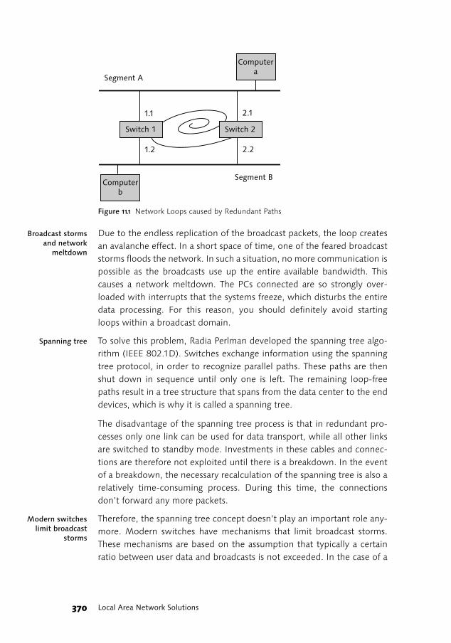
In this example, there are two potential paths from computer a to com-puter b, which, in each case, lead through a connection to switches 1 and2. What happens if computer a sends a packet to computer b, but com-puter b is not yet listed in the address tables of either switch?
1. Computer a in network Segment A transfers a packet. Both switcheslearn that computer a can be reached through connection 1.1. or 2.1,and broadcast the packet through all the other connections as they donot yet know the address of computer b.
2. Thus, there are two identical packets in Segment B. Because bothswitches are connected with each other via Segment B, these packetsalso reach both switches cross-over, then through connection 1.2 or 2.2respectively. Since the packet still contains computer a as the sender,both switches learn that computer a suddenly seems to be located inSegment B.
3. As computer b is still not recognized, the packet is once again replica-ted through connections 1.1 or 2.1 into Segment A, from which it ori-ginates and is then duplicated. As the switches do not know each otherand each switch continuously broadcasts the packet into the other seg-ment, an endless loop is generated.
Local Area Network Solutions370
Figure 11.1 Network Loops caused by Redundant Paths
Broadcast stormsand network
meltdown
Due to the endless replication of the broadcast packets, the loop createsan avalanche effect. In a short space of time, one of the feared broadcaststorms floods the network. In such a situation, no more communication ispossible as the broadcasts use up the entire available bandwidth. Thiscauses a network meltdown. The PCs connected are so strongly over-loaded with interrupts that the systems freeze, which disturbs the entiredata processing. For this reason, you should definitely avoid startingloops within a broadcast domain.
Spanning tree To solve this problem, Radia Perlman developed the spanning tree algo-rithm (IEEE 802.1D). Switches exchange information using the spanningtree protocol, in order to recognize parallel paths. These paths are thenshut down in sequence until only one is left. The remaining loop-freepaths result in a tree structure that spans from the data center to the enddevices, which is why it is called a spanning tree.
The disadvantage of the spanning tree process is that in redundant pro-cesses only one link can be used for data transport, while all other linksare switched to standby mode. Investments in these cables and connec-tions are therefore not exploited until there is a breakdown. In the eventof a breakdown, the necessary recalculation of the spanning tree is also arelatively time-consuming process. During this time, the connectionsdon’t forward any more packets.
Modern switcheslimit broadcast
storms
Therefore, the spanning tree concept doesn’t play an important role any-more. Modern switches have mechanisms that limit broadcast storms.These mechanisms are based on the assumption that typically a certainratio between user data and broadcasts is not exceeded. In the case of a
Switch 1 Switch 2
Computera
Computerb
Segment A
Segment B
1.1
1.2
2.1
2.2

371High Availability for Local Networks
broadcast storm, those broadcasts that go over the limit are distorted.You should, however, implement such mechanisms with caution. On theone hand, there is the danger that good broadcast packets could also beeliminated; on the other hand, the danger exists that a real broadcaststorm could be disguised. In both cases, problems that are difficult toidentify can emerge.
11.1.1 Link Aggregation
Different manufacturers provide different technologies that can bundleseveral 100Mbps or 1 Gbit/s connections (link aggregation). For theoperating system, the bundled connections represent a single logicalinterface with a single MAC and IP address. Due to this aggregation, theload is distributed to the parallel connections. This provides higher per-formance and redundant paths. If a connection breaks down, the datatraffic is automatically transferred to the remaining connections withinthe bundle.
However, link aggregation supports only parallel point-to-point connec-tions between two devices. This means the switches that are linkedthrough link aggregation still represent single points of failure. In addi-tion, the different cables of a bundle are generally placed in the sameposition so that they’re exposed to the same potential risks and can besimultaneously destroyed.
11.1.2 Highly Available Network Clusters for Business-critical Applications
Installing redundant cables and switches for each important work centerin a company would lead to exorbitantly high costs and immensely com-plex configurations. An alternative approach, (which was developed byone of the authors) is based on the view of the business functions in aenterprise to design highly available networks for business-critical appli-cations.
Human redundancy
From this hands-on approach, you can assume that a high availability isessential at the department level, but for individual work centers, a cer-tain downtime can be tolerated. This is because at the department levelthere is always a functional redundancy since each user is assigned a sub-stitute for leave, sickness, and so on. This substitute is often the colleagueat the next desk. Even if the substitutes themselves are not there, theemployee whose connection to the SAP system is disrupted can use thecolleague’s PC (or the colleague’s connection wall socket). This fact can

Local Area Network Solutions372
be used to grant also that work will be done even in case a networkdevice is going down.
Rules for networkclusters
In order to avoid SPoF on the business functions level, network clustersmust be configured according to the following simple rules:
� An employee’s PC that fulfills an important business function shouldnever be connected to the same network switch as that of his or hersubstitute.
� For this reason, every network cabinet must contain at least twoswitches with separate connections (uplinks) to the data center.
� If possible, the connections should be executed on different paths.
� There must be at least two backbone switches installed in the datacenter (in different fire protection zones).
� Each clustered SAP server must be connected through separate net-work cards to these backbone switches.
Network clusters can most easily be implemented by intelligent patching,which consists of linking the end device connections on the patch panelsof the network cabinet with the connections of the switches. You cangenerally assume that adjacent PCs are provided for employees with thesame business functions that can mutually cover for each other. In orderto meet the requirements of a network cluster, you only need to attachthe end device connections with straight numbers on the patch panel toone switch and those with odd numbers to another switch.
When this concept is implemented methodically, single points of failureare avoided at the business function level as well as network loops andinactive standby connections. Network clusters can be implemented withplug & play components of any manufacturer.
Two simple examples illustrate the network cluster concept. In Figure11.2, the sales departments PCs are located on the left-hand side and thelogistics department PCs are located on the right-hand side.
� Scenario 1: One of the switches (or its uplink) in the sales departmentbreaks down. Every other work center is dead, but the rest remainoperational. In a typical network environment in which all PCs of thesame department are connected to the same switch, the entire depart-ment cannot process any more orders.
� Scenario 2: One of the backbone switches in the data center breaksdown. In half of the hosts the connection breaks down, but the rest, how-

373High Availability for Local Networks
ever, remain operational. If it takes too long to replace the backbone,switch cross connections between the switches can be used as a bypass.
Figure 11.2 Highly Available Loop-Free Network Cluster
The network cluster concept ensures that at least one in every two PCs ofa department has a connection to the SAP system at any time from a net-work perspective, and the business tasks of a department can be exe-cuted in any situation. The investments are the same as for a redundantlydesigned network based on the spanning tree concept. Alternatively,there is a network cluster but no convergence time, and the availablebandwidth is substantially higher due to the utilization of all availablelinks and connections.
11.1.3 Error-tolerant Meshed Networks
For a network cluster, even when a backbone switch or link breaks down(see Scenario 2 in the previous example), the operation of the enterprisecan be maintained. However, in this case, up to 50 % of the work centerscan lose their network connection. Due to switch meshing, the networkcluster concept can be extended so that even the breakdown of a back-bone component can be absorbed. This means that the local network isextensively error tolerant.
Switch meshingSwitch meshing is a technology originally developed by Hewlett Packard,which enables the creation of a completely meshed local network infra-structure without generating the risk of loops and subsequent network
SAPServer
BackboneSwitch
BackboneSwitch
Switch
Switch
SAPServer
Switch
SwitchClientPCs
ClientPCs
ClientPCs
ClientPCs
ClientPCs
ClientPCs
ClientPCs
ClientPCs

Local Area Network Solutions374
meltdown due to broadcast storms. Currently, other manufacturersimplement this technology as well. All links and connections are alwaysactive. On the basis of load statistics, algorithms distribute the data trafficequally to all links and prevent broadcast landslides.
Figure 11.3 Error-Tolerant, Completely Meshed Network
If the “intelligent patching“ described for network clusters is implementedwith completely meshed switches, even in the case of a failing backbonecomponent, the full operation of the network can be ensured. The switcho-ver time in an SAP cluster test environment, after turning off a backboneswitch, was under two seconds in a running operation. The switch took placetransparently for the application and user without losing any transactions.
UPS Units Are Also for Network Cabinets
To ensure the availability of the SAP infrastructure, in areas where thereare more frequent voltage fluctuations, Uninterrupted Power Supply(UPS) units should be used. The ability of a UPS unit to filter and stabi-lize the power supply voltage is more important than bridging longpower outages. A switching operation in the high-voltage power grid ofthe electricity supplier only causes the office lighting to flicker, but theswitches and routers may restart and cause network downtime. How-ever, USP units are also active components that must be monitored andmaintained.
SAPServer
BackboneSwitch
BackboneSwitch
Switch
Switch
SAPServer
Switch
SwitchClientPCs
ClientPCs
ClientPCs
ClientPCs
ClientPCs
ClientPCs
ClientPCs
ClientPCs
Redirection of Data Flow< 2 sec

375Wires and Fibers
11.2 Wires and Fibers
Today, basically two cable types are used for local networks: lines withtwisted pairs of copper wires and fiber optics cables. Both have typeshave advantages and disadvantages, because of their physical characteris-tics.
11.2.1 Copper Cables
The area of end device connections is generally based on twisted paircopper wires. This type of cable has existed since the first telephone sig-nals were transferred. Throughout the years, on the one hand, the trans-fer frequencies have become much higher; on the other hand, there areessentially more sources of disturbance. Fortunately, twisted pair cableswere also developed to the same extent. Therefore, we can say withassurance that twisted copper cables actually do meet the requirementsof high-speed data transfers. Compared with optical fibers, copper cablesare much easier to install and, consequently, are more cost-effective.
Copper cables—“lets twist again”
Twisted pair cable consists of two copper wires. Each wire is encased in itsown color-coded insulation, twisted around one another. Multiple pairsare packaged in an outer sheath, or jacket, to form a twisted-pair cable.The twist of the cable is essential for electrical noise immunity and mustgo as near as possible to the connectors of the wall receptacles andpatch-panels. By varying the length of the twists in nearby pairs, thecrosstalk between pairs in the same cable sheath can be minimized. Thetypical nominal impedance is 100 ohms.
For data networks in companies, structured cabling in accordance withEN 50173-12, ISO/IEC, or EIA/TIA-568 category 5 onwards has becomestandard.
The decisive quality attribute for top quality data cables is the symmetryof the cable. Different twist lengths of pairs that are placed next to eachother avoid crosstalk. In this context, it is important that the cables arenot only symmetrically stranded but also precisely finished.
2 General requirements for application-neutral communication systems in offices(2003).

Local Area Network Solutions376
Shielded orunshielded?
Contemporary data networks operating with frequencies that are locatedin the middle area of the VHF radio band (Very High Frequency). Themetallic conductors act like antennas for these frequencies, for receivingas well as for transmitting. STP cables contain a metal shield to reduce thepotential for electromagnetic interference (EMI). EMI is caused by alter-nating electromagnetic fields from other sources such as electric motors,power lines, high power radio and radar signals but also by flickering flu-orescent tubes in the vicinity that may cause disruptions or interference,called noise.
There are, however, a variety of shielding solutions for data cables. Fromthe most simple aluminum polyester compound film, through combina-tions of tin-plated twisted meshwork and compound film, to expensivemetal shields, you can find all possible constructions.
The names of the various shielded (Shielded Twisted Pairs, STP) andunshielded (Unshielded Twisted Pair, UTP) cable types are quite confus-ing. STP also encompasses Screened Shielded Twisted Pair (ScTP) and FoilTwisted Pair (FTP) cables. Within UTP, there are paradoxically alsoShielded Unshielded cables (S-UTP) with a complete external shielding,but without individual shielding of the pairs.
STP cables At first glance, STP cables appear to be immune to any interferences,because of their shielding. But, unfortunately, this is not the case. As thegrounded shield also acts as an antenna and transforms the incominginterferences into a current, which induces a current in the signal wires inthe opposite direction. As long as both currents are symmetrical, theyeliminate each other. Any discontinuity in shielding or asymmetry in thecurrents between the shield and signal wires acts as a source for elec-tronic noise. Therefore, STP cables are effective only if the entire link fromone end to the other is continuously shielded and properly grounded.However, this can in turn cause severe problems by amperage flow overthe shield in cases, where the electrical supply grid has no separatedgrounding.
High Bandwidth is not Equal to High Frequency
There only appears to be a connection between the transfer frequencyand the achievable bandwidth. By using highly developed signal encod-ing processes, all high-speed technologies such as Fast Ethernet and GigaEthernet, as well as ATM, don’t exeed 310 MHz as the transfer frequency.Technologies with higher bandwidth are based on fibre optic cables.

377Wires and Fibers
UTP cableFor UTP cables, the physical shield is replaced by improved variations ofthe twisting as well as sophisticated filtering techniques in the networkdevices. Disturbances are equally induced in both conductors and there-fore eliminate each other. Throughout the years, the UTP cables haveconstantly been improved so that they now fully meet the requirementsof category 5.
Despite a heated debate over the years about the advantages and disad-vantages of shielded versus unshielded twisted pair cables, a final conclu-sion has still not been reached. In Europe, STP is the main preference, notonly to protect data signals against outside emissions, but because corre-sponding regulations require the protection of the environment againstthe emissions of data signals. UTP cables are used generally in the rest ofthe world. In any case, reliability is always determined by the quality ofthe cable manufacturing and proper installation.
11.2.2 Fiber Optics Cables
A fiber optics cable consists of a bundle of optical threads (fibers), inwhich messages modulated onto light waves propagate along the direc-tion of the fiber because of internal reflection. The reflection occurs dueto the different refraction indices between the core and the coating.Fiber-optic network cabling is made up of at least two strands of opticalfiber running parallel to each other in a plastic “zip-cord“ jacket, or mul-tiple fibers in a single jacket.
Electromagnetic Compatibility (EMC)
Another factor to consider when choosing a cabling system relates toelectromagnetic compatibility (EMC). In the U.S. and Germany, EMCregulations have existed for years. However, the implementation of theEuropean EMC Directive 89/336/EEC in 1989 has refocused attentionon EMC. With the increased amount of electronic equipment in theaverage workspace, EMC becomes increasingly more important. Excessradiation from one piece of equipment can adversely affect perfor-mance of another piece of equipment. EMC refers to the ability of anelectronic system to function properly in an environment where severalpieces of equipment radiate electromagnetic emissions. This meansthat every electronic system, which includes all copper based cablingsystems, must meet this directive.

Local Area Network Solutions378
Multi-ModeFibers
There are two different types of optical fibers: Multi-Mode Fibers (MMF)and Single-Mode Fibers (SMF). In this context, “mode“ refers to theeffect of spreading a light signal in an optical fiber, resulting in light-raysfollowing different paths (or modes) down the fiber (modal dispersion).Multimode fiber (MMF), with a core diameter of 62.5μm allows a lightsignal to take various zigzag paths. This modal dispersion causes somelight rays to arrive later at the end of the fiber. Due to the undesired runt-ime differences caused by these different modes, the range of MMFcables is limited to 1.5 miles (2 km).
Figure 11.4 The Route of Light Rays in Single-Mode and Multi-Mode Fiber Optics Cables
Single-modefibers
Single-mode fiber (SMF) with a core diameter of only 9 microns allowsonly one path for the light to take due to the fiber's very small diameter.Single-mode fibers and components are more expensive than Multi-mode fiber, but allow connectivity up to 12 miles (20 km). Cheap PlasticSMF fibers can be used only for very short connections, they absorb thelight rays earlier because plastic is not as clear as glass.
Multi-mode fiber is designed for coupling light from low cost LED3-basedtransmitters. Single-mode fiber is only suitable for laser-based transmis-sion.
There are varieties of connectors (FDDI-MIC, ST, SC-Duplex etc.) forMMF as well as for SMF. Be sure to use the same diameter and connec-tors throughout your infrastructure. Project deadlines are easily missedwhen plugs at fibers do not fit the active components, and adapter cablesare not on hand.
Single-Mode Fiber Multi-Mode Fiber
Fiber Core
JacketJacket
Fiber Core
3 Light Emitting Diodes.

379Wires and Fibers
Advantages ofoptical fibers
Fiber optics cables can be used for all current network technologies. Incomparison to network connections made of metal, fiber optic cableshave numerous advantages:
� Optical fibers enable a larger bandwidth than copper cables.
� Optical fibers are not sensitive to electromagnetic radiation and don’temit any by themselves. This means that all regulations are meet bydefault.
� Optical fibers are immune to lightning strikes and power line tran-sients.
� Metal free Optical fibers cannot generate any ground loops.
� Optical fibers are much thinner and lighter in weight than metal wires.
� It is very difficult to tap eavesdrop on optical fibers without beingnoticed, making this very secure from electronic eavesdropping.
DrawbacksOn the other hand, fiber optics cables also have some disadvantages:
� Fiber optics cable connectors are high precision parts. An exact align-ment of the fiber inside the connector housing and proper polish ofthe fiber end is crucial for connectivity quality.
� Installing connectors on site is time consuming and requires high pre-cision work. The alternative of fusion welding strands with prefabri-cated connectors (called pigtails) on site needs expensive equipment.
� Together with the higher costs for the cable itself, the deployment offiber-optic cable costs more than twice that of a category 5 copperconnection. The “per port“ price of active fiber optic components(hubs, switches, router modules) is typically twice the price of theircopper counterparts. The prices for long range single-mode cables andcomponents are even higher than for multi-mode
� Glass fibers are more fragile than wire and sensitive and age under theimpact of hydrogen ions. They must therefore be protected againstmoisture through special coatings. However, this protective layer isalso subject to aging.

Local Area Network Solutions380
11.2.3 Installation Guidelines for Cable Networks
Good craftsmanship, together with using high quality components, has adirect relationship to how long your cabling infrastructure will last. Asmentioned before, high-speed data links have higher demands thanplain-old telephone lines. To make matters worse, the effects of poorinstallation work may not be immediately evident!
Deformation or mechanical stress during installation causes most cablefailures. Deformation changes the physical properties responsible for highfrequency transmission. Even when the cable looks flawless from the out-side, irreversible degradation of transmission properties is suspectedwhen too much stress is applied to the cable. Mechanical stresses as wellas temperature levels are part of the ISO/IEC 11801 standard “GenericCabling for Customer Premises.“ The installation of network infrastruc-tures should be dedicated to certified contractors, familiar to the specialdemands of data cabling.
However, even with equipment, which has been checked and conformsto the standards, problems still exist, as with increased demands on thenetworks, the reserves in the transfer parameters decrease.
Visual inspections An example is the standard of fitting the data cables in the connectioncomponents. The standard for this does provide for a visual inspection,but this is rarely carried out. Generally, people content themselves withthe test logs created by cable scanners. For instance, in distributor panelswhere the cable sections that have been stripped of the isolation are nar-rowly guided along the blank wire ends of the neighboring cable, this canlead to a short circuit between the wire and the foil shield if the latterchanges, for example, because the temperature of the cabinet interior
Case Example: Mice in Cable Conduit
In a company, a complete administration building was suddenly with-out network based IT services. The reason behind this was a fiber opticscable that had been gnawed through in a cable conduit. Rodents like tobuild their houses in cable conduits, and their offspring like to test theirteeth on the cables. Since fiber optics cables can only be spliced byusing special tools, this led to a downtime lasting several days. Evenrodent-safe cables and mousetraps are therefore investments thatincrease availability of enterprise service architectures and IT services ingeneral.

381Potential Equalization, Grounding, and Lightning Protection
increases. During an acceptance test on cabling, it is therefore critical thatyou perform visual inspections.
With fiber-optic cables, you can run into problems later on as well, evenif they have been installed according to the standards. Here the problemscan mainly be found in the preconfigured plugs. These plugs are very sen-sitive to scratches, dust, and inept treatment when being mounted. Wealso recommend that you use a microscope when conducting checks. Youcan find additional information and further considerations when execut-ing acceptance tests in Mißbach/Hoffmann,4 which is also worthwhilereading for small changes or enhancements carried out by your internalelectrician.
11.3 Potential Equalization, Grounding, and Lightning Protection
Frequently, sporadic disturbances and breakdowns occur in data net-works without a clear reason. Connections become extremely slow, mon-itor screens flicker, assemblies burn through or after a thunderstorm, andentire facilities break down at once. Furthermore, individual employeesmay be marginalized, because strangely it is only always their PCs that go“mad.“
In many cases, however, the real reason for these breakdowns can befound in the potential equalization and grounding. Apart from the datanetwork cabling in every building, there is also cabling for the power sup-ply. People often overlook the fact that these two cable networks arelinked via the grounding, and massive disturbances of the data networkscan occur if the power supply network is not designed as IT-compatible.
Potential displace-ments
In order to ensure an electricity flow, a wire (L) is required from the elec-tricity source to the consumer, as well as a retracting wire (N). A thirdwire is stipulated as a ground wire or protective earth conductor (PE). Asthe 230V alternating current is tapped from a 380V three-phase network,this results in a 5-wire network or TN-S system with three conductingphases and a common neutral and ground wire for each phase.
The security function of the protective earth conductor is ensured, even ifthe protective earth conductor is connected to the neutral cable that isalso grounded, and thereby forms a “combined“ PEN conductor (that is,a retracting circuit (N) plus a protective earth conductor (PE)). Such cou-
4 Mißbach, Hoffmann: SAP Hardware Solutions—Servers, Storage, and Networks formySAP.com. Prentice Hall 2000.
Local Area Network Solutions382
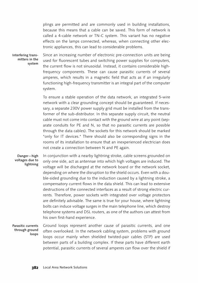
plings are permitted and are commonly used in building installations,because this means that a cable can be saved. This form of network iscalled a 4-cable network or TN-C system. This variant has no negativeeffects on the lamps connected, whereas, when connecting other elec-tronic appliances, this can lead to considerable problems.
Interfering trans-mitters in the
system
Since an increasing number of electronic pre-connection units are beingused for fluorescent tubes and switching power supplies for computers,the current flow is not sinusoidal. Instead, it contains considerable high-frequency components. These can cause parasitic currents of severalamperes, which results in a magnetic field that acts as if an irregularlyfunctioning high-frequency transmitter is an integral part of the computersystem.
To ensure a stable operation of the data network, an integrated 5-wirenetwork with a clear grounding concept should be guaranteed. If neces-sary, a separate 230V power supply grid must be installed from the trans-former of the sub-distributor. In this separate supply circuit, the neutralcable must not come into contact with the ground wire at any point (sep-arate conduits for PE and N, so that no parasitic currents are possiblethrough the data cables). The sockets for this network should be marked“only for IT devices.“ There should also be corresponding signs in therooms of its installation to ensure that an inexperienced electrician doesnot create a connection between N and PE again.
Danger—highvoltages due to
lightning
In conjunction with a nearby lightning stroke, cable screens grounded ononly one side, act as antennae into which high voltages are induced. Thevoltage will be discharged at the network board or the network socket,depending on where the disruption to the shield occurs. Even with a dou-ble-sided grounding due to the induction caused by a lightning stroke, acompensatory current flows in the data shield. This can lead to extensivedestructions of the connected interfaces as a result of strong electric cur-rents. Therefore, power sockets with integrated over voltage protectorsare definitely advisable. The same is true for your house, where lightningbolts can induce voltage surges in the main telephone line, which destroytelephone systems and DSL routers, as one of the authors can attest fromhis own first-hand experience.
Parasitic currentsthrough ground
loops
Ground loops represent another cause of parasitic currents, and oneoften overlooked. In the network cabling system, problems with groundloops occur mainly when shielded twisted-pair cables (STP) are usedbetween parts of a building complex. If these parts have different earthpotential, parasitic currents of several amperes can flow over the shield if

383Wireless Networks
grounded on both ends. These ground loops can lead to a degradation ofnetwork performance, and even to a damage of network components.
When installing STP cables, you must ensure that grounding occurs onlyat one end of the grounded link. For UTP cables, ground loops are not anissue, because of the design of these cables. Fiber-optic cables are themost secure way of eliminating damage caused by parasitic currents ofany type.
11.4 Wireless Networks
Wireless technologies in recent years have undergone rapid developmentin terms of both their bandwidths and their increased use. In 2004, 42 %of all notebooks were already equipped with Wireless LAN (WLAN) func-tionality, and, according to estimates from the IDC market research insti-tute, this percentage will rise to 98 % by 2007.
11.4.1 WLAN Standards
Wireless local networks (Wireless LAN, WLAN) are defined in the normsIEEE5 802.11 and ISO CD8802-11. After an initial 2Mbps in the first
Fire Protection
The insulation of data cables generally consists of flammable syntheticmaterials, mainly polyethylene and PVC. To reduce the threat to peopleand material, Building Codes generally require cables that does notgenerate toxic fumes when burning, such as FEP (fluoro-ethylene poly-mer) in air ducts, air plenums, and other environmental air spaces.
In the event of a fire, these cables also don’t generate corrosive gas-esand the smoke gas density is considerably lower. Therefore, PVCcables are banned in building installations in an increasing number ofcountries.
It is for good reason that building insurers in recent years placed majoremphasis on the issue of fire protection. According to the insurers, allcable conduits in ceilings that run at a right angle to an emergencyroute must have a full fire protection. This also applies to all laterchanges. You should therefore always ensure that the cable installationsare in accordance with the regulations of the property insurers.
5 Institute of Electrical and Electronics Engineers.

Local Area Network Solutions384
802.11 standard without additional letters at the time, 802.11b followedwith 11Mbps and 802.11g followed with up to 54Mbps (~30Mbps net)with three channels on the 2.4 GHz frequency. Some manufacturersalready provide systems with transfer rates of 100 Mbit/s, with the assur-ance that modifications resulting from a standard that will subsequentlybe introduced can be imported in the form of a software update. Con-trary to this, 802.11a and 802.11h each have eight channels in the 5 GHzband at their disposal. However, this band is also used by radar systemsand earth observation satellites. A certain detection threshold in theinteraction with Dynamic Frequency Selection (DFS) is supposed toensure that these radar systems and satellites are not disturbed by WLAN.
The 802.11alphabet
The 802.11 alphabet also knows a range of other letters, which reflectmodifications made according to country-specific regulations or modifi-cations made for functional enhancements.
For example, variant 802.11h was introduced to comply with the require-ments of some European countries for a automatic adaptation of thetransmission power (Transmission Power Control, TPC), which is sup-posed to further reduce the probability of interferences. Without TPCand DFS, 5 GHz radio networks in Europe can be subject to very rigidobligations that limit the operation to ranges of less than 20 meters inbuildings.
The letters e, l, and f, are used for function enhancements. IEEE 802.11fdefines the Inter Access Point Protocol (IAPP) for roaming betweenAccess Points of different manufacturers. The 802.11i standard is sup-posed to protect wireless networks against unauthorized access by imple-menting encryption processes and user authorization. The 802.11eattempts to enable a prioritizing of certain applications such as voice-overIP (VoIP) in the WLAN. However, no bandwidth can be guaranteed here;rather, the access point tries to implement the different priority levels inas far as possible.
Standard 802.11a uses Orthogonal Frequency Division Multiplexing(OFDM) for transmission with up to 12 channels depending on the coun-try, while standard 802.11b is based on Direct Sequence Spread Spec-trum (DSSS). The development of 802.11g was made possible after theFederal Communications Commission (FCC) had released the OFDMtechnology in the 2.4 GHz band.
802.16a In addition to the 802.11 family, the IEEE has ratified norms for evenhigher speeds. 802.16a or Wimax6 uses the frequency range of 2 to 11
385Wireless Networks
GHz for transfer speeds of 70Mbps with coverage of almost 30 miles,while 802.16b is supposed to enable even 134.4Mbps in the frequencyrange of 10 to 66 GHz. The Wimax Forum7 aims to have an unlicensedband for 802.16a with 5.8 GHz and two licensed bands with 2.5 and 3.5GHz. Other bands are to follow later. The radius of a cell should realisti-cally be set to 20 miles, regardless of whether there are obstaclesbetween the sender and the recipient. Market researchers expect a wideavailability of these technologies by 2008.
While using WLAN for mobile applications is indispensable, the rapiddevelopment of radio technologies to ever-increasing bandwidths andthe growing use of laptops with integrated WLAN interfaces beg thequestion of whether avoiding cabling altogether, for stationary work cen-ters as well, is a real possibility. There are, however, some constraints toconsider that you won’t typically find in the manufacturers’ brochures.
Bandwidth is dependent on the distance
Due to physical laws, at a given transmitting power, the bandwidth isdependent on the distance. As you can see in Table 11.1, the rules are asfollows: The larger the distance, the lower the actual bandwidth. Forincreasing frequencies, obstacles cause mounting problems to electro-magnetic waves.
6 Worldwide Interoperability for Microwave Access, the corresponding name of theEuropean ETSI is HiperMAN as this technology is generally regarded as suited forMetropolitan Area Networks (MAN).
7 Go to www.wimaxforum.org.
A Practical Example of WLAN
In the feeder railway of a lignite mine, information about shuntingtasks, the sequence of wagons, wagon data, and the currently coveredlength of shunting tracks is transferred to the handheld PCs of shuntersand locomotive drivers via 802.11b WLAN.
To minimize the number of access points, the antennae were alignedalong geographically defined lines of sight, and the locomotives wereequipped with an access point repeater that ensures radio coverage forthe shunter’s handheld in the area of his shunting unit. In addition, thelocomotive drivers enter operating data such as engine and compressorruntimes, or the fuel consumption directly through pocket PC andWLAN on the driver’s console.

Local Area Network Solutions386
In addition, all WLAN protocols cause considerable overheads, so out ofa bandwidth of up to 11Mbps, approximately only 7Mbps can be usedfor user data and this can only be reached when you are close to thetransmitter (i.e., access point).
ISM band Most WLAN products use the ISM (industry, science, and medicine) bandin a range of 2.4 GHz. However, the transmitting power in the ISM bandis limited to 500 mW so the highly sensitive medicinal diagnosis systemsdon’t get disturbed. For this reason, mobile telephones that have anessentially higher output power must not be used in hospitals, and youshould resist the urge to download your latest email to the computer viayour cell phone while sitting in the waiting room of the intensive careunit. The low transmitting power reduces the range correspondingly. Sim-ilar restrictions also apply to the 5 GHz band.
In addition, a basic disadvantage of radio networks is that all participantsmust share the available bandwidth. It is precisely because the ISM bandis license-free that it is also used by many other systems. Examples ofother systems include the wireless control of erection cranes and thehobby area. RC cars and planes are therefore potential sources of infer-ences for WLANs. The Bluetooth short distance radio technology, whichallows mobiles, headsets, handhelds, and printers to communicate witheach other, uses also the 2.4 GHz ISM band. Even a microwave can posea possible source of disturbance since it also often works in the 2.4 GHzrange.
5 Gigahertz band Like the 2.4 GHz range, the 5 GHz band is similarly utilized by radio appli-cations. However, because of the higher number of channels, more userscan share a radio cell.
All end devicesshare the
bandwidth
All end devices set to a specific channel necessarily share the bandwidth.Therefore, the 11Mbps that exist on paper can easily become only 600kbit/s in actuality, and even this cannot be guaranteed. In certain circum-stances, this leads to drastically increased response times for an SAP userwho is connected to an SAP system through WLAN if a coworker is cur-rently loading a large email attachment on the same channel. If access
11Mbps 5.5Mbps 2Mbps 1Mbps
Open country 70 yds. / 66 m 100 yds. / 91 m 135 yds. / 125 m 187 yds. / 171 m
In buildings 30 yds. / 28 m 38 yds. / 35 m 47 yds. / 43 m 58 yds. / 53 m
Table 11.1 Correlation between WLAN Coverage and Bandwidth

387Wireless Networks
points are used as radio bridges, the range increases but not the band-width as the traffic from the neighboring cell also has to be transferred.
Power users in fixed cabled network connec-tions
In order to cover larger areas and user numbers, more cells must beinstalled. The access points required for this, in turn, need a conventionalcabling, which means that you cannot avoid providing a fixed cabled net-work. Practice has shown the benefit of equipping power users with bothstationary work centers and a fixed cable network connection, and ahotspot for the shared desk area in the office.
11.4.2 Installation Guidelines for Wireless Networks
In order to determine the locations for WLAN access nodes (so calledWLAN basis station), the construction drawings for the building shouldbe inspected for hidden metal constructions such as steal reinforcementand water pipes, which shield the radio waves like a Faraday cage andtherefore disrupt the WLAN connection. But, even a larger number ofpeople have a negative influence on the performance of a radio network(the high water content of human beings damp the radio waves). Due tostarkly reduced prices for access points, you can simply install some ofthem on a trial-and-error basis.
WLAN channel layout
Using the Direct Sequence Spread Spectrum (DSSS) technology, the IEEE802.11b standard provides 13 channels for transmission; however,because these channels overlap each other, they can’t be used in directproximity (side by side). At the end, there are three triples (channels 1, 6,and 11; channels 2, 7, and 12; and channels 3, 8, and 13), which don’toverlap each other.
This means that in an ideal scenario a maximum of three access pointswith a total bandwidth of 33Mbps can cover a room without any distur-
Directional Antennae for Improved Radio Coverage in Warehouses
In warehouses and manufacturing, wireless mobile terminals with barcode readers are frequently used to compile data along with the mobiledata entry interface of SAP Materials Management (MM-MOB).
The steel racks and the steel reinforced concrete walls in high-bay rack-ing, however, absorb the transmitting energy of omnidirectional anten-nae. Directional antennae that radiate into the warehouse alleys canensure a stable connection.

Local Area Network Solutions388
bance. Anyone can send and receive on a different frequency without anyinterference provided there’s a sufficient distance between the senderand the receiver. To ensure complete redundancy, the radio field of anaccess point must also be covered by the radio field of a second accesspoint.
Figure 11.5 Channel Layout for WLAN
For larger WLAN installations, you must ensure that access points, whichare situated next to each other, are configured with different channelnumbers. Otherwise, they would mutually disrupt each other. Here youmust consider that access points necessarily radiate through severalfloors. As the individual radio channels also partly radiate into neighbor-ing frequencies, for instance, when node A transmits on channel 1, thedirectly adjacent access node B should be set to channel 6, and node Cshould be set to channel 11. Therefore a carefully designed channel lay-out is necessary for larger WLAN installations.
In larger office buildings that are used by several companies, there arealso problems if the WLANS of individual companies overlap and therebycause interferences. If services in the form of hot spots are provided forthird parties, in some countries a concession is required, which is cur-rently still free of charge.
WLAN—aparadise for
hackers?
Experience has shown that many WLANs are insufficiently secured.According to a study by Ernst & Young from 2003, over 50 % of users donot change their default passwords to access points, 25 % configure theService Set Identifier (SSID) in such a way that it reveals the network name,and in many cases, even the company name or the IP address. But, at least48 % of WLAN users use a Virtual Private Networking (VPN) to protect
1 6 11
11 1
6 111
66

389Wireless Networks
their data. Only a third of users implement a firewall between wired LANand WLAN. In total, WLANs are included in only 33 % of the companies inthe technical and regulatory regulations for the security concept.
Hiding the SSIDIn addition to encryption, the access procedure can also enhance security.Each WLAN has Service Set Identifier (SSID) as a name. So clients cancommunicate with the radio network, they must know this SSID andenter it when logging onto the radio network. In hot spots, the SSID isoften sent out as a broadcast. If this is prevented, the clients must alreadyknow the SSID in order to be able to create any connection. All other par-ticipants are excluded from communication with this WLAN.
However, during the authentication process, each client sends the SSID inplain text to the access point, which can easily and most assuredly beeavesdropped on by an attacker. Unfortunately, this is unavoidable,because several different radio networks can exist within one footprint.
MAC-address access control lists
Some manufacturers have integrated access control lists (ACL) in theiraccess points so they can only permit those clients with known MACaddresses to communicate in the WLAN. Although this excludes partici-pants with unknown MAC addresses from using the network, this mech-anism can also easily be overcome by attackers with simple methods.During communication in a radio network, the MAC addresses must betransferred unencrypted. This enables the attacker to tap valid MACaddresses, which they can then configure in their own WLAN cards byusing the corresponding software.
Fixed keys do not provide sufficient security
Technologies like Wired Equivalent Privacy (WEP) which the key is storedin the access point and the notebook, generally do not provide sufficientsecurity, because they can be relatively easily cracked by scanning thedata traffic.
WLANs also Threaten Wired Networks
For companies, the growing use of notebooks with built-in WLAN con-nectivity increased the likelihood that the security of their networkswas being compromised. The reason behind this was and is that badlyconfigured notebooks function as WLAN access points when they areconnected to a company LAN by cable without disabling WLAN func-tionality. In most cases users are not aware of this security hole andbreach security unintentionally.

Local Area Network Solutions390
Therefore, we advise you not to implement any WLAN-based encryption;instead, you should establish a secured connection between the clientand the firewall with a powerful IPSec encryption in a VPN. In addition,an overall concept from authentication, authorization, accounting, andencryption is necessary.
Security from endto end
In “typical“ access point concepts, only the WLAN-side “air interface“ ofthe access point is encrypted while the data in the cabled part is trans-ferred unencrypted. So called WLAN switches can be positioned in sucha way that their network port is logically immediately connected to thefirewall or the VPN server. As data traffic on the cable route between theWLAN switch and the antenna systems is encrypted in the same way as inthe air interface, security is guaranteed from one end to the other with-out the end user having to install a VPN client.
For big installations, a large number of access points means that configu-ration and administration becomes time-consuming and costly. These dif-ficulties were overcome on classic, cabled networks by automatic, rule-based switching on network levels 2 and 3. For WLANs, there are corre-sponding concepts of Wireless LAN switching.
Wireless LAN-switching
To do this, a WLAN switch is installed (for example, from HP, Nortel,Extreme Networks, or Proxim), from which access points and access tothe network can be administered centrally. Thus, the decentrally installedaccess points become pure antenna systems that convert only radio sig-nals to Ethernet packets. The “intelligence“ of the WLAN is concentratedin the wireless switch. In general, access points don’t even need an IPaddress. Their power supply can be ensured through “power over Ether-net“ according to the 802.3af standard, so that, apart from the Ethernetcable, no further installation is necessary.
For real mobile users, which roam within a WLAN network between thefootprints of different access points, a wireless switch provides a singlesign on (SSL) and roaming times that are typically under 30 seconds.However, strictly speaking, this is not the kind of roaming we know frommobile phones that roam between the networks of different providers.Instead, it is an interruption-free handover from one radio cell to another.
Furthermore, many WLAN switches offer functions such as automaticchannel selection—where the layout of the radio cells is automaticallyoptimized—and preemptive roaming (wireless load balancing).

391Wireless Networks
11.4.3 Ad-Hoc Networks
BluetoothAd-hoc network technologies such as Bluetooth8 were developed toenable a dynamic connection establishment between mobile devicessuch as wireless DECT phones, laptops and PDAs. Recently, this list hasbeen complemented by hands free speaking systems and headsets. Orig-inally, the Bluetooth concept was only intended to replace the cablesbetween the phone handsets and their peripheral devices with a radioconnection. However, the user spectrum was very quickly expanded toinclude the world of the personal computer. The developed is controlledby the Bluetooth Special Interest Group.9
Network configu-ration on the fly
While WLANS require a fixed configuration, ad-hoc networks are basedon a master-slave system where a master device controls the changingconnections in a Piconet cell. As the type and number of devices in thecell can change unexpectedly, the routing protocol used by Bluetoothmust be capable of dynamically reconfiguring the network “on the fly.“
The designers of Bluetooth, too, have decided to use the license-free2.4000 GHz–2.4835 GHz ISM frequency band. Since this band is alreadyused by so many other wireless services, Bluetooth uses an AdvancedFrequency Hopping Technology (AFH) to avoid interference problems,which have made life difficult for other ISM band users. The AFH conceptuses 79 different radio channels from among which it switches 1.6 timesper second. Thus, a channel is used only for 625 microseconds before theswitch is made to the next randomly selected channel.
Bluetooth currently allows a transfer rate of up to 1Mbps which corre-sponds to a real throughput rate of approximately 720 kbit/s. Powermanagement in Bluetooth is divided into three different performanceclasses: Class-1 devices work with 100 milliwatt (mW) and have a rangeof up to 110 yards (100m). Class-2 devices work with 2.5 mW and havea range of up to 10 yards (10m). Class 3 manages with 1 mW and reachesbetween 5 inches (10cm) and 1 yard (1m). This relatively short range hasthe advantage that the transfer channels are not blocked by Bluetoothdevices operating from a greater distance.
8 Named after the Viking prince Harold Bluetooth, who unified Denmark, Sweden,and Norway in the 10th century.
9 Go to www.bluetooth.com.

Local Area Network Solutions392
11.4.4 Mobile Communications
For the mobile business applications, in particular, which are provided bySAP with its NetWeaver product, the data services of mobile communi-cations providers are an interesting alternative for replication—that is,replication between the mobile client (mostly a Personal Digital Assistant,PDA), and the SAP Mobile Engine Infrastructure Server. The data quanti-ties to be transferred are typically so small that the mobile technologiescurrently available have no problems with them. However, even theserelatively small volumes of data, which are usually ignored when design-ing a network, can become an issue, especially when it comes to connec-tion costs.
11.5 Voice—Data Convergence
One area in which the infrastructure consolidation has rapidly developedin recent years is the merging of voice and data services. After all, this isnot very surprising because the transmission of information through elec-tronic signals is really integral to both concepts.
All through onecable
One of the reasons why Ethernet has become more popular than tech-nologies such as TokenRing was the development of 10BaseT by Hewlett-Packard, where, instead of coaxial cables (10Base2 and 10Base5),twisted-pair cables of category 3 could be used, which at the time corre-sponded to the existing telephone cables used in the US.
American-type phone cable consists of two pairs of separately twistedwires. Alternatively, the telephone cables predominantly used in Europeconsist of four wires that are twisted together (see Figure 11.6). This struc-ture results in a stronger crosstalk that obstructs a usage for the Ethernet.
Figure 11.6 American and European Telephone Cables
1 2
1 2
1 American standard phone cable
2 European standard phone cable

393Summary
Meanwhile, at least in company networks, the quantity of bytes for datatransfers has exceeded that for voice communication by far. It is no longerabout transferring data via a modem through proprietary telephone net-works, but rather about transferring voice through open IP infrastructures(Voice over IP, VoIP). Here, one advantage is that, due to suitable com-pression algorithms (codecs), the necessary bandwidth for a telephoneconversation is so low that it can be easily “saddled“ on the normal Eth-ernet connection of an SAP user. However, the particular requirements oflanguage services must be considered here, especially with regard tolatency. Therefore, the use of VoIP technologies depends on the constantavailability of Quality of Service (QoS) in the IP infrastructure of a com-pany.
Power supply for IP telephones
Another important difference between language and data networks isthat in conventional telephone systems the end devices are generally pro-vided with the necessary operational voltage through the connectioncable. Even if a PC with headset was perfectly sufficient (and offers sub-stantially more functionalities), experience shows that users don’t like tobe without their familiar phones on their desks; admittedly, these phonesdon’t have to be booted. These problems can be solved through patchfields, which superimpose a direct voltage on the high frequency data sig-nals (Power over Ethernet, PoE) to supply power to the IP telephones. If,on top of that, the IP phones are also daisy chained into the connectionof the PC, only one Ethernet connection per user is necessary.
Voice-data convergence needs high availa-bility
In this way, the consolidation of voice and data transfer can drasticallyreduce the costs for the local network infrastructure. However, we knowfrom experience that, in order for VoIP to be accepted by the users, avail-ability must be guaranteed, which is akin to that of the familiar tele-phone, and it can only be achieved with the concepts described above.
11.6 Summary
Modern LAN technologies provide sufficient bandwidth to connect alarge number of users to an SAP system. However, there are certainrequirements to be considered regarding reliability:
� Design the network backbone as redundant, but be aware of thethreats caused by network loops.
� Implement highly available network clusters and error-tolerantmeshed networks together and patch intelligently.

Local Area Network Solutions394
� Do not forget to equip all network cabinets with an uninterruptedpower supply.
� For connections between buildings and in the rising mains area, allfiber optics cables are required due to their lack of sensitivity to light-ning strokes and ground loops.
� The quality of the installed cables and the proper installation has a sig-nificant impact on the performance of your network which is usuallyunderestimated. The wiring of a floor or entire building is a majorinvestment. Using low quality cables or unqualified installers can voidthis investment to a great extend, leading to significant cost in future.A wiring investment should be planned as carefully as a hardwareinvestment project.
� The cabling for power supply also plays a pivotal role for disruption-free operation. Neutral wires and protection wires should never beused together (PEN); between building parts with different groundingpotential, only fiber optics cables should be used.
� Radio networks are suitable for connecting individual mobile SAPapplications. For large numbers of users, a distribution across severalaccess points is necessary, which requires a well devised channel layoutplan.
� WLANs must be integrated into the security concept of the company.
523Index
Index
Symbols.NET 101
AABAP Development Workbench 50Activity pattern 126Adapter engines 48Adaptive
Application Services 428, 433Availability 446Data center virtualization 426Database mover 447Deployment solution 437Distributed printing solution 437Dynamic solution installation 444Dynamic workload adaption 441ESA 419Failover by hand 438Generation of Test Systems 442Hard partitions 424Hardware Consolidation 421Hardware Virtualization 420Instant capacity 426Licence keys 436Micropartitions 423Network Attached Storage, NAS 431Operating System deployment 433Operating System provisioning 432Parking lot concept 439Partitioning 421Patch management 444Pool controller 427Printing 437Process resource management 422Rapid backup/restore 443Reference cases 439round-up syndrome 420Server pool 428Shared netboot 432Single system image 432, 437Software logistics 432Storage 431Storage Area Networks, SAN 431Storage pool 428System archiving 446
System copy service 443System stacking 440Temporary Instant Capacity 426Virtual machines 423Virtual partitions 422, 423VMware 423
Adaptive computing 417Adaptive Computing Controller, ACC
55, 428Adaptive Load Balancing, ALB 350Adaptive Microsoft Virtual Server 423Adobe Output Pack 305Advanced Planner and Optimizer, APO
80, 230Advanced Volume Printing, AVP 304Agents 464AMD Opteron 162, 185APO 24, 80APO optimizer 82, 265Application instance 134, 258Application Link Enabling, ALE 46, 243Application load 136Application Operations Monitoring
467Application server 228Archive Development Kit, ADK 232ArchiveLink 300Archiving 231, 232ARIS Tool Set 474Audit trail 71Availability 237
BBackup 333
Data 270Local backup 276Logical consistency 270Network backup 277Offline-backup 275Online-backup 276Recovery 280Redo logs 275SAN Backup 278SAP-backint interface 279Veritas NetBackup 279

Index524
Zero-downtime 278Bandwidth
Batch jobs 332Log shipping 272Print output 329RFC connections 332User connection 328
Basel II 65, 238Batch jobs 125Batch processing 472Batch work processes 98Benchmarking, deficits 313Best-of-breed 510BEx Analyzer 291, 324BEx Web Application Designer 291BI Meta Model Repository, BI MMR
39Bit errors 167Blade servers 172Buffer 103Business Explorer, BEx 291, 322Business Server Pages 28, 322BW 24BW front end 38BW Web queries 324
CCache hierarchy 167Cache memory 166, 183CCMS XAL interface 461CCMS XMV interface 461ccNUMA 169, 181Central instance 99, 257Central system 320Central User Administration 57Change Alert Monitor 253Change Management 114CISC architecture 161Citrix Presentation Server, CPS 292,
322Client 98Cluster
Campus Cluster 261Heartbeat 255
Cluster Consistency Service 269Code pages 107Collaborative Business 63
Common User Programming Interface-Communication, CPI-C 332
Composite Application Framework, CAF 27, 50
Composite applications 50Computer Center Management
System, CCMS 55, 474Computer technologies 160Conflict Resolution Transport, CRT 71Consolidation
application 510logical 504potential savings 506SAP instances 508SAP system merge 504server consolidation 506storage consolidation 506storage subsystems 230system consolidation 507technical 506
Costsavailability costs 491, 494complexity costs 491, 493cost structures 490efficiency analyses 494fixed 491hardware costs 491infrastructure 490investment calculation 495load-dependent 493Return on Investment, ROI 496risk analysis 496sensitivity analysis 496software logistics costs 491, 494staffing 490, 493system operation 491Total cost of ownership, TCO 497variable 491volume-dependent 493
cProjects 64CPU load 130
measurement 132Crossbar-SMP 169Customer Interaction Center, CIC 129Customer Relationship Management,
CRM 72

525Index
DData hydrant 246Data replication 206
remote 207Database
Availability 196Data files 190Data space 190Dev space 190File sharing 193Index files 190Log files 191Program files 191Read/write accesses 189Rollback files 191Security 196Tablespace 190Temporary data 192
Database cache 205Database instance 133Database layer 103Desktop Management Initiative, DMI
471Development system, DEV 51, 112, 228Device Wizard 297Dialog work process 98Disk
Archive log 218Automatic performance optimi-
zation 225Block I/O Striping 223Burst transfer 195Business copy 228Cache size 205, 215Common Internet File System, CIFS
213Continuous access 228Disk arrays 197Disk caches 204Distributed parity 200Distributed parity stored in
duplicate 201eDAC 202Filers 213Frontend IOPS 215Hardware RAID 201Hot spare area 227Hot spare disk 200
I/O channels 219iDAC 201IOPS rate 195Just a Bunch of Disks, JBOD 198Leveling 225Logical Unit, LUN 225Mirroring 199Network File System, NFS 213RAID-0 198RAID-1 199RAID-5 200RAID-6 201Redo logs 218Redundant Array of Independent
Disks, RAID 197Rotational seek time 195SATA 209SCSI 209Serial Advanced Technology
Attachment, SATA 209Small Computer System Interface,
SCSI 209Software RAID 201Storage
consolidation 230Storage subsystems 197Storage virtualization 225Stripe size 198Striping 198Structuring subsystems 220Track bit density 195Ultra ATA 208Ultra Direct Memory Access, UDMA
208Virtual RAID, Vraid 225Write back 205Write through 205
Disk array controller, DAC 201Disk groups 225Dispatcher process 98Document archiving 233Domain Name Service, DNS 348Downtime 236
application problems 282avoiding 243environment-related 246Failover systems 254hardware maintenance 250

Index526
operating system maintenance 253planned 237Rolling disaster 262Security patches 254unplanned 236
EEarlyWatch 153, 284eCATT 113Eclipse Java Development Framework
50Emergency performance 240Employee Self Services, ESS 70, 296EMT64 162, 185Encryption 357Enjoy SAP 24Enqueue process 98Enterprise Application Integration, EAI
45Enterprise Buyer Professional, EBP 146Enterprise Core Component, ECC 62Enterprise Process Integration, EPI 46Enterprise Services Architecture, ESA
235, 419, 452Environment 246EPIC architecture 163Evaluation system 52e-Valuator 502Extended Computer Aided Test Tool,
eCATT 113
FFailover
APO 264Cluster consistency 266Configurations 259Continental cluster 247, 263HP Cluster Manager 259HP Serviceguard 259Local cluster 261Manual 260Metro Cluster 263Microsoft Cluster Server, MSCS 263Real Application Cluster, RAC 257Single System Image Cluster 270Sizing 265Solutions 254Test 268
Transparent Application Failover, TAF 257
Windows 263Federal Communications Commission,
FCC 384Fiber Channel Arbitrated Loop, FC-AL
211Fiber Channel Fabric 211Fiber Channel over IP 213Fiber Channel, FC 210Fiber Distributed Data Interface, FDDI
368File systems 203Forms
management 301printer-based 303server-based 304
Frontend 289
GGartner Group Chart of Accounts 500Gateway work process 98GoingLive 153GoingLive Service 284Grid Computing 115GuiXT 293
HHard disks 135Hardware infrastructure 248Heartbeat 333High availability 244High Performance File System, HFS
203Host name 344HP Data Protector 279HP OpenView 29, 461
II/O Architectures 171IA-32 162IBM Logical Partitions 423IBM Workload Manager 422IDS Scheer 474Industry solutions 71, 126InfiniBand 172Info structures 232InfoCubes 35, 140

527Index
Input/Output operations per second, IOPS 194, 214
In-Q-My 100Interaction Center 74, 325Interactive forms based on Adobe
software 303Intermediate Document, IDoc 46Internationalization 106, 295Internet Communication Manager 104Internet Graphics Service 105Internet Pricing and Configurator, IPC
265Internet Transaction Server 24, 97IP stack 319iSCSI 212IT Infrastructure Library, ITIL 114, 454IT Service Application Management,
ITSAM 460IT Service Management Reference
Model, ITSM 114, 454, 456ITSM
Application administration 456Application help desk 457Application maintenance 456Application monitoring 457Application Performance Moni-
toring 470Authorization concept 459Availability management 458, 459Baselining 460Business Process Management 474Business Process Monitoring 474Business Process Operation 474Capacity Management 458Change management 451, 459Configuration management 451,
460Configuration Management
Database, CMDB 460, 475Desktop Management 471Enterprise System Management 462Escalation Management 458Help desk management 451Incident exchange 476Incident Management 458Job-Scheduling 472OpenView Business Process Insight,
BPI 475
Operations Management 458, 464Problem Management 458Responsible, Accountable, Consult,
Inform, RACI 477Security Management 459Service desk 475Service Level Agreement, SLA 457Service level management 451, 457Service Oriented Architectures, SOA
475
JJ2EE engine 99Java Central Services 257Java Connector 51, 100Java Dispatcher 102Java Enqueue Service 102Java Message Service 102Java Server Pages 322Java Server Processes 102JavaGUI 291Journaling File System, JFS 203
KKeepalives 322Knowledge management 29Knowledge Warehouse 26, 40
LLatency time 319Layer-3 switching 320LCApps 81Legal patches 284Lightweight Directory Access Protocol,
LDAP 58Linear Tape Open, LTO 279Linux 175
36-bit 18664-bit 186tainted kernel 252
LinuxLab 175liveCache 184, 265
key figures 145Load factors 123Lock tables 258Log files 217Log shipping 271Logical errors 272

Index528
Logical Volume Manager, LVM 223Low Speed Connection, LSC 321LSC option 321
MMain memory 132
architectures 165determining the requirement 133
Management Information System, MIS 34
Manager Self-Service, MSS 70MaxDB 81, 180Memory addressing 183Message process 98Microsoft Active Directory 58Microsoft System Management
System, SMS 471Microsoft Windows Terminal Server,
WTS 292Mirroring
asynchronous 208synchronous 208
Multicore 164Multilevel crossbar 169Multithreading 164mySAP All-in-One 92mySAP Analytics 68mySAP Business Intelligence 34mySAP Corporate Services 69mySAP CRM 73
BackWeb server 76Case Management 79E-Mail Response Management
System, ERMS 75Field Sales und Field Service 73Index Management Service, IMS 76Intelligent Product Advisor, IPA 76Interaction Center, IC 74Internet Pricing & Configurator, IPC
75Internet Sales 75Network load 325permanent shopping basket 76SAPConnect 75SAPPhone 74Sizing 143Vehicle Management System, VMS
78
mySAP ERP 62Biller Direct, BD 76Discrete Industries and Mill
Products, DIMP 72Distributor Reseller Management,
DRM 72E-Learning 68Employee Self-Service, ESS 70Enterprise Core Component, ECC
62Equipment and Tools Management,
ETM 72E-Recruiting 67Financials Real Estate 89Homebuilding 72Industry Solutions 71Integrated Product and Process
Engineering, iPPE 72Kanban 72Logistics Execution System, LES 66Maintenance and Service Planning,
MSP 72Management Cockpit 69Management of Internal Controls,
MIC 65Manager Self-Service, MSS 70Multiple Output Planning, MOP 72Plant Maintenance, PM 67Production Planning, PP 66Project System, PS 67Quality Management, QM 66Sales & Distribution, SD 65Strategic Enterprise Management/
Business Analytics, 68Travel Management 69Warehouse Management, WM 66
mySAP Financials 64mySAP Human Capital Management,
HCM 67mySAP Mobile Asset Management,
MAM 33mySAP Mobile Business 32mySAP Mobile Procurement 32mySAP Mobile Sales for Handhelds 32mySAP Mobile Services for Handhelds
32mySAP Mobile Supply Chain Mana-
gement 33

529Index
mySAP Mobile Time and Travel 32mySAP Operations 65mySAP PLM 87
Asset Life Cycle Management, ALM 89
cFolder 147cProjects 64, 87Digital mock-up, DMU 87Easy Document Management 88EH&S Expert 90Environment, Health & Safety, EH&S
90Life Cycle Data Management 88Mobile Asset Management, MAM
89New Product Development and
Introduction, NPDI 87Quality management 89Recipe Management 89
mySAP SCM 79APO liveCache 81Available-to-Promise, ATP 81Characteristics combinations 144Compliance Management 91Customs Management 91Demand Planning, DP 80Event Management, EM 83Inventory Collaboration Hub, ICH
84Optimizer 81Production Planning - Detailed
Scheduling, PP-DS 80SAP Global Trade Services, GTS 91Supply Chain Cockpit 81Supply Network Planning, SNP 80Transportation Planning - Vehicle
Scheduling, TP-VS 81Vendor-Managed Inventory, VMI 81
mySAP SCM Advanced Planner and Optimizer, APOSizing 144
mySAP solutions, dimensioning 143mySAP SRM 85
Bidding Engine 86Business-to-Business Procurement,
B2B 86Business-to-Business Procurement,
BBP 86
Content Integrator 85Enterprise Buyer Professional, EBP
85, 86Live Auction Cockpit Web Presen-
tation Server, LAC W 86Supplier Self-Services, SUS 86
mySAP.com 24
NNetwork
Access Control Lists, ACL 389Adaptive Fault Tolerance, AFT 349Address buffering 347Address resolution 344, 346Alias name 346Asymmetrical DSL, ADSL 398Asynchronous Transfer Mode, ATM
400Availability 336, 352Bandwidth 314, 318Bandwidth on demand 407, 413Bluetooth 391Broadcast storm 370Client IP address 357Client-based load balancing 352Committed information rate, CIR
399Compression 407Copper cable 375Costs 318, 405Cryptography 409Data prioritizing 408dial on demand 407Digital Subscriber Line, DSL 398Discovery and Mapping 468DNS zone file 348Domain Name Service, DNS 346,
348Dynamic Host Configuration
Protocol, DHCP 344Electromagnetic compatibility, EMC
377Estimating Bandwidth 327Failure tolerance 411Fast Ethernet 368Fiber optics cable 377Filtering 406Fire protection 383

Index530
Frame relay 399Full qualified domain name 345Gigabit Ethernet 368Ground loops 382Grounding 381High available LAN’s 368Highly available LAN cluster 371Host file 347Host name 346Integrated Services Digital Network,
ISDN 397Inter Access Point Protocol, IAPP
384Internet 401Internet Service Provider, ISP 401IP address concepts 342IP name 346ISM band 386Keepalives 407Latency time 315, 400Leased lines 397Lightning protection 381, 382Link aggregation 350, 371Load analyzing 326Load balancing 352Local Area Network, LAN 367Local loop 412Logical structures 342Management 318Microwave links 414Mobile communications 392Multihomed host 349Multi-mode fibers, MMF 378Multiprotocol label switching, MPLS
402Name resolution 344, 347Name services 346Network Address Translation, NAT
342Network cache 408Network Information Service, NIS
348Network loops 369Network meltdown 370Network probe 470Operation Monitoring 469Performance 312
Permanent Virtual Connection, PVC 399
Point of Presence, PoP 398, 411Port Address Translation, PAT 343Potential equalization 381Power over Ethernet, PoE 393Private address spaces 342Proxy server 407Quality of Service, QoS 393, 400,
408Redirection 353Remote monitoring 470Resource Reservation Protocol,
RSVP 408Response time 313Reverse lookup 347Rodent protection 380Round Trip Time, RTT 317Round-robin DNS 354SAP network interface, NI 347SAP Web Dispatcher 355Satellite connections 404Secure Network Communication,
SNC 409Secure Socket Layer, SSL 357Security 409Service Set Identifier, SSID 388Session cookies 356Session persistence 356Short hold mode 398Single-Mode Fibers, SMF 378Spanning tree 370Spoofing 407SSL session ID 357STP cable 376Switch meshing 373Switchover 350Twisted pair cable 375URL rewriting 356UTP cable 377Very Small Aperture Satellite, VSAT
404, 415Virtual private network, VPN 410Voice - Data convergence 392Voice over IP, VoIP 393Well-known TCP ports 408Wide Area Network, WAN 395

531Index
Windows Internet Name Service, WINS 346, 348
Wired Equivalent Privacy, WEP 389Wireless LAN, WLAN 383WLAN Channel layout 387X.25 399
Network WLAN switching 390New Dimensions 24NIPING 317Novell eDirectory 58
OOne Button Disaster Recovery, OBDR
280Online access 297Online Analytical Processing, OLAP
35, 181, 194Online documentation 323Online Transaction Processing, OLTP
35, 139, 181, 193Operating Costs 489Operating system maintenance 253Operating system parameters 253Operating systems 173, 251
stability 251Operational Data Store 141Operational Data Store, ODS 36Operations Management
Event-Correlation 466OS/400 177Output 298
Coupling type 330Frontend print 331Local spooling 330Output device 330Remote spooling 330
Output management 306Output management systems, OMS
306Output Server 306
PPaging 133PA-RISC 160Partner Connectivity Kit 49Patch strategy 251PCI bus 171PCI Express 171
PCI-X 171Performance guarantee 150Performance, disk drives 195Ping 317Platform migration 284
Benefits 513Costs 512TCO 510
Pool server 428Portal Collaboration Package 26PowerPC 161Process Resource Manager 422Processor architectures 161Product Availability Matrix 159Production system, PRD 52Proxy server 407
QQuality assurance system, QAS 51, 112,
229Queue theory 131Quorum disk 255
RR/2 24R/3 24Radio frequency identification, RFID
83RAS philosophy 248Raw device 203Read cache 165Real-Time Enterprise 452Recovery 333Remote Function Call, RFC 46, 332Remote replication 207Replicated enqueue 106, 258Response time 129, 312, 405Retention period 135RFID 83RISC architecture 162Risk analysis 239RMON 470Rounding-up effect 420
SSandbox system 52SAP Advanced Technology Group 281SAP APO

Index532
network load 325SAP Auto-ID Infrastructure, AII 84SAP Business Information Warehouse,
BW 34, 229Szing 140
SAP Business Intelligence 26, 34SAP Business One 92SAP BW 34
BI Java Development Kit 39Business Explorer, BEx 38InfoCubes 35Information Broadcasting 38Internet Graphics Service, IGS 292Network load 324ODS objects 37, 141Precalculation Service 37Universal Data Integration, UDI 39
SAP Console 297SAP Content Server 41SAP DB 81, 180SAP Enterprise Portal, EP 26, 27, 28
Application sharing server 31Collaboration Business Package 31Content Management 31Drag & Relate 28iFrames 28Index Management Server, IMS 30iView 28Page Builder 28Portal Content Directory, PCD 28Portal Development Kit 31Sizing 139Text Retrieval and Information
Extraction, TREX 30Unification Server 29
SAP Event Management 82SAP Exchange Infrastructure, XI 27, 46,
243sizing 142
SAP Gateway 316SAP GUI 96, 289, 320SAP GUI for Java 291SAP High Performance Analytics, HPA
39SAP instance 97SAP Internet Sales 75SAP KW
Cache server 41
Content Server 41Internet Knowledge Servlet, IKS 41Knowledge Provider, KPro 41
SAP Master Data Management, MDM 27, 43Central Master Data Management,
CMDM 43Content Consolidation, CC 43Content Integrator 44Master Data Harmonization, MDH
43Master data server 44MDM adaptors 44Periodic Inbound Collector, PIC 43Sizing 143
SAP MI Client 33SAP MI Server 34SAP Mobile Engine 26SAP Mobile Infrastructure, MI 32, 297
Sizing 139SAP NetWeaver 26
Dimensioning 138SAP NetWeaver Developer Studio 33
Change Management Service, CMS 54
Component Build Service, CBS 54Design Time Repository, DTR 54Software Deployment Manager,
SDM 54SAP NetWeaver Development Envi-
ronment 50SAP Quick Sizer 120SAP Remote Function Call, RFC 343SAP Router 316SAP Secure Network Communication,
SNC 331SAP Solution Manager, SSM 54, 461SAP spool system 299SAP Strategic Enterprise Management
37SAP System Landscape Directory, SLD
429SAP Web AS 27
ABAP Development Workbench 50ABAP personality 100Batch work process 98Central instance, CI 99

533Index
Central User Administration, CUA 57
DCOM connector 101Dialog work process 98Dispatcher 98Enqueue process 98Extended Computer Aided Test
Tool, eCATT 113extented Transport Management
System, eTMS 52Gateway process 98Instance 97Internet Communication Manager,
ICM 100, 104Internet Graphics Service, IGS 105Internet Transaction Server, ITS 97Java Connector, JCo 51, 100Java personality 100Message process 98NetWeaver Developer Studio 50Open SQL for Java 104Single Sign-On, SSO 57Software logistics 114Spool work processes 98System Central Services, SCS 106Transport Management System,
TMS 114Update work process 98User Management Engine, UME 57Web dispatcher 102
SAP Web Dispatcher 102SAP xApps 50SAP XI
Adapter engine 48Application adapters 47Integration Builder 46Integration Server 48Partner Connectivity Kit, PCK 49Plain J2SE adapter engine 48Proxy framework 47
Sapacoscol 429Sapacosprep 429SAPcomm 300SAPConnect 75SAPLPD 331Saposcol 429SAPPhone 74SAPS 136
SAPscript 302Sarbanes-Oxley Act 65Scalability 180Scale up –scale out 513SCOR model 82Seasonal peak loads 126Security
Authentication via Cookies 358Authentication via X.509 certificates
358Backup 364Cryptography 409Demilitarized zone 361Firewalls 361Networks 409SAP Web dispatcher 362Secure Network Communication,
SNC 409SSL encryption 358Subdivided DMZ 359User authentication 358
Server page programming model 294Service and Application Management
451Service Level Agreement, SLA 120, 121,
150Shadow database 271
Backup 273Libelle 273Recovery 275
Simple Network Management Protocol, SNMP 464
Single sign-on, SSO 358Sizing 119
Concurrent user 123Evaluation 152Limits 127Load-based 128Logged-on user 123Named user 123Questionnaires 127Quick Sizer 120Response time 121Round-up syndrome 420System metrics 122Transaction-based 124User-based 123
Sldreg 429

Index534
Small and Midsize Business, SMB 26Smart Forms 302Snapshot 207SNMP traps 464Solaris Resource Manager 422Solution Lifecycle Management 54Solution Manager BPO 474SPARC 161Split brain syndrome 255Spool management 299Spool request 299Spool work process 299, 329SQL tuning 216Stability 241Storage
Backend IOPS 216Data clones 278Direct attached storage mana-
gement 469FATA disks 280iSCSI 249LUN masking 431Mirroring with LVM 261NAS management 469Physical I/O 431Rapid backup/restore 443SAN-Management 469Snapshots 278Split mirror 442Split mirrors 278Zero downtime backup 443Zoning 431
Storage Area Networks, SAN 211Storage subsystems
Sizing 214Support Desk 56Swap space 190Swapping 133Symmetrical Multiprocessing 168System copies 281System Landscape Directory, SLD 48,
55, 476System management
tools 451System operation 285
Cost blocks 491System performance 180System platform, selection 159
System throughput 136
TTag Libraries 294, 297Tape systems 279TCO benchmarking 501TCO project 500TCO, Consolidation 504Temporary sequential database, TemSe
299TemSe 299Test system 51TN-C system 382TN-S system 381Traceroute 317Transaction 124Transport Management System, TMS
52Transport requests 114TREX 26, 30, 76
UUnbuffered I/O 203Unicode 48, 108, 184, 285Unicode encoding schema 110Uninterrupted power supply, UPS 412Unix 174Unix File System (UFS) 203Update work process 98User Management Engine 57User-based dimensioning 123
VVendor managed inventory, VMI 478Virtual arrays 202Virtual users 125
WWeb Dynpro 322
ABAP 296network load 323
Web dynpro 28, 293Web Dynpro architecture 294Windows 174Windows Terminal Server, WTS 322WinGUI 290Workload Management Pack 422

535Index
ZzOS 177