adaptive nonlinear image enlargement using wavelet transform
TRANSCRIPT

US 20030194150A1
(12) Patent Application Publication (10) Pub. No.: US 2003/0194150 A1 (19) United States
Berkner (43) Pub. Date: Oct. 16, 2003
(54) ADAPTIVE NONLINEAR IMAGE ENLARGEMENT USING WAVELET TRANSFORM COEFFICIENTS
(76) Inventor: Kathrin Berkner, Menlo Park, CA (Us)
Correspondence Address: Michael J. Mallie BLAKELY, SOKOLOFF, TAYLOR & ZAFMAN LLP Seventh Floor 12400 Wilshire Boulevard Los Angeles, CA 90025-1026 (US)
(22) Filed: Apr. 16, 2002
Publication Classi?cation
(51) Int. Cl.7 ............................. .. G06K 9/32; G06K 9/54 (52) US. Cl. .......................................... .. 382/300; 382/302
(57) ABSTRACT
A method and apparatus for enlargement and resolution enhancement of images in the Wavelet domain is described. In one embodiment, the method comprises receiving a Wavelet representation of an image, Where the Wavelet representation comprises Wavelet coef?cients, and perform ing localized adaptive interpolation on the Wavelet coef?
(21) Appl. No.: 10/124,290 cients in the Wavelet domain.
RECEIVED PROCESSING DIGITAL IMAGE I i ONE LEVEL (GAMMA
FORWARD CORRECTION AT A SPECIFIC ENLARGER ’ OUTPUT
DP! 802 ——> HALFTONING) ‘———> 804 RESOLUT|0N R FOR PRINTING
800 ~ 801 AT 2R DPI
*1 “NJ 803

Patent Application Publication Oct. 16, 2003 Sheet 1 0f 11 US 2003/0194150 A1
101 102 103
FIG. 1

Patent Application Publication Oct. 16, 2003 Sheet 2 0f 11
201 202 203 204
H H H CLL ClLH dHL dHH
\ I \ I
20 \ I sq CL \ dH 1206
\ I
I l I I 2071 CL D 1208
I I I
200k . I lint I
I I I
I
21O'L I INT
FIG. 2
US 2003/0194150 A1

Patent Application Publication Oct. 16, 2003 Sheet 3 0f 11 US 2003/0194150 A1
301
K RECEIVE AN IMAGE GIVEN IN WAVELET COEFFICIENTS II I
WRERFORM A FIRST VERTICAL INVERSE WAVELET TRANSFORM ON [302 COLUMNS OF A FIRST COEFFICIENT MATRIX OF THE IMAGE AND COLUMNS OF A SECOND COEFFICIENT MATRIX OF THE IMAGE
PERFORM A SECOND VERTICAL INVERSE WAVELET TRANSFORM ON [303 COLUMNS OF A THIRD COEFFICIENT MATRIX OF THE IMAGE AND ,
L COLUMNS OF A FOURTH COEFFICIENT MATRIX OF THE IMAGE I
V
FOR EACH COLUMN IN A RESULT OF THE FIRST VERTICAL INVERSE? 304 WAVELET TRANSFORM, SET A CORRESPONDING EVEN-NUMBERED I COLUMN IN A FIRST VERTICALLY COARSER GRID IMAGE EQUAL TO THE COLUMN IN THE RESULT OF THE FIRST VERTICAL INVERSE
WAVELET TRANSFORM
I FOR EACH COLUMN IN A RESULT OF THE SECOND VERTICAL
INVERSE WAVELET TRANSFORM, SET A CORRESPONDING EVEN- I305 NUMBERED COLUMN IN A SECOND VERTICALLY COARSER GRID IMAGE EQUAL TO THE COLUMN IN THE RESULT OF THE SECOND
VERTICAL WAVELET TRANSFORM
FOR EACH COLUMN AND EACH ROW IN A FIFTH COEFFICIENT I MATRIX, SET AN ELEMENT IN THE COLUMN AND ROW OF THE FIFTH COEFFICIENT MATRIX EQUAL TO A SUM OF A FIRST ADDEND AND A SECOND ADDEND, WHEREIN THE FIRST ADDEND IS AN ELEMENT IN A COLUMN AND A ROW IN THE SECOND COEFFICIENT MATRIX, THE 306
COLUMN AND ROW IN THE SECOND COEFFICIENT MATRIX I CORRESPONDING TO THE COLUMN AND THE ROW IN THE FIFTH COEFFICIENT MATRIX, AND WHEREIN THE SECOND ADDEND IS AN ELEMENT IN A COLUMN AND ROW IN THE FOURTH COEFFICIENT
MATRIX, THE COLUMN AND THE ROW IN THE FOURTH COEFFICIENT MATRIX CORRESPONDING TO THE COLUMN AND THE ROW IN THE
FIFTH COEFFICIENT MATRIX '
FIG. 3A
Patent Application Publication Oct. 16, 2003 Sheet 4 0f 11 US 2003/0194150 A1
FOR EACH ROW OF EACH OFF-NUMBERED COLUMN IN THE FIRST vERTICALLY COARSER GRID IMAGE, SET AN ELEMENT IN THE ROW OF THE ODD-NUMBERED COLUMN EQUAL TO A SUM OF A FIRST
ADDEND AND A SECOND ADDEND, WHEREIN THE FIRST ADDEND IS A PRODUCT OF A FIRST PARAMETER AND AN ELEMENT IN A SAME I307 ROW OF AN EVEN-NUMBERED COLUMN LEFT OF THE OD D
NUMBERED COLUMN, AND WHEREIN THE SECOND ADDEND IS A PRODUCT OF A DIFFERENCE AND AN ELEMENT IN A SAME ROW OF AN EVEN-NUMBERED COLUMN RIGHT OF THE ODD-NUMBERED
COLUMN, WHEREIN THE DIFFERENCE IS EOUAL TO ONE MINUS THE FIRST PARAMETER
I FOR EACH ROW OF EACH ODD-NUMBERED COLUMN IN THE SECOND VERTICALLY COARSER IMAGE, SET AN ELEMENT IN THE ROW OF THE ODD-NUMBERED COLUMN EQUAL TO A SUM OF A FIRST
ADDEND AND A SECOND ADDEND, WHEREIN THE FIRST ADDEND IS A PRODUCT OF THE FIRST PARAMETER AND AN ELEMENT IN A SAME If308
ROW OF AN EVEN-NUMBERED COLUMN LEFT OF THE OD D NUMBERED COLUMN, AND WHEREIN THE SECOND ADDEND IS A
PRODUCT OF A DIFFERENCE AND AN ELEMENT IN A SAME ROW OF AN EVEN-NUMBERED COLUMN RIGHT OF THE ODD-NUMBERED
COLUMN, WHEREIN THE DIFFERENCE IS EQUAL TO ONE MINUS THE FIRST PARAMETER
PERFORM A HORIZONTAL INvERSE WAVELET TRANSFORM ON I309 ROWS OF THE FIRST vERTICALLY COARSER GRID IMAGEAND ROWS
OF THE SECOND VERTICALLY COARSER GRID IMAGE
I FOR EACH ROW IN A RESULT OF THE HORIZONTAL INvERsE
WAVELET TRANSFORM, SET A CORRESPONDING EVEN-NUMBERED [310 ROW IN A HORIZONTALLY COARSER GRID IMAGE EQUAL TO THE ROW IN THE RESULT OF THE HORIZONTAL INvERSE WAVELET
TRANSFORM
FIG. 3B

Patent Application Publication Oct. 16, 2003 Sheet 5 0f 11 US 2003/0194150 A1
FOR EACH EVEN-NUMBERED COLUMN OF EACH ODD-NUMBERED ROW IN THE HORIZONTALLY COARSER GRID IMAGE, SET AN ELEMENT IN THE EVEN-NUMBERED COLUMN OF THE ODD
NUMBERED ROW EQUAL TO A SUM OF A FIRST ADDEND AND A SECOND ADDEND, WHEREIN THE FIRST ADDEND IS A PRODUCT OF A 311 THIRD PARAMETER AND AN ELEMENT IN A SAME EVEN-NUMBERED COLUMN OF AN EVEN-NUMBERED ROW ABOVE THE ODD-NUMBERED
ROW, AND WHEREIN THE SECOND ADDEND IS A PRODUCT OF A DIFFERENCE AND AN ELEMENT IN A SAME EVEN-NUMBERED COLUMN OF AN EVEN-NUMBERED ROW BELOW THE ODD
NUMBERED ROW, WHEREIN THE DIFFERENCE IS EQUAL TO ONE MINUS THE THIRD PARAMETER
FOR EACH ODD-NUMBERED COLUMN OF EACH ODD-NUMBERED ROW IN THE HORIZONTALLY COARSER GRID IMAGE, SET AN
ELEMENT IN THE ODD-NUMBERED COLUMN OF THE ODD-NUMBERED ROW EQUAL TO A SUM OF A FIRST ADDEND AND A SECOND
ADDEND, WHEREIN THE FIRST ADDEND IS A PRODUCT OF THE 312 THIRD PARAMETER AND AN ELEMENT IN A SAME ODD-NUMBERED
COLUMN OF AN EVEN-NUMBERED ROW ABOVE THE ODD-NUMBERED ROW, AND WHEREIN THE SECOND ADDEND IS A PRODUCT OF A
DIFFERENCE AND AN ELEMENT IN A SAME ODD-NUMBERED COLUMN OF AN EVEN-NUMBERED ROW BELOW THE ODD-NUMBERED ROW, WHEREIN THE DIFFERENCE IS EQUAL TO ONE MINUS THE THIRD
PARAMETER
II
CLIP A RESULTING IMAGE BACK TO A RANGE
SET EACH ELEMENT IN THE RESULTING IMAGE HAVING A 313 VALUE BELOW THE RANGE TO A LOWEST VALUE IN THE ‘ I
RANGE AND SET EACH ELEMENT IN THE RESULTING IMAGE HAVING A VALUE ABOVE THE RANGE TO A HIGHEST VALUE IN
THE RANGE
FIG. 3C

Patent Application Publication Oct. 16, 2003 Sheet 6 0f 11 US 2003/0194150 A1
400
RECEIVING PROCESSING UNIT 401 UNIT 402
FIG. 4

Patent Application Publication Oct. 16, 2003 Sheet 7 0f 11 US 2003/0194150 A1
50] 502

Patent Application Publication Oct. 16, 2003 Sheet 8 0f 11 US 2003/0194150 A1
RECEIVE AN 601 IIvIAGE HAVING A f PERFECT STEP
EDGE
I INTERPOLATE THE PERFECT 602 STEP EDGE f
EXACTLY WHILE ENLARGING THE
IMAGE
FIG. 6

Patent Application Publication Oct. 16, 2003 Sheet 9 0f 11 US 2003/0194150 A1
wow mmmvm/jzw
8“ $65: is zmomwzék Ei><>> 5528mm wwmw>z_ N .UE

Patent Application Publication Oct. 16, 2003 Sheet 10 0f 11 US 2003/0194150 A1
vow PDnFDO
00m E 20_.rD|_OwmE ED 7 oczmaw < E

Patent Application Publication Oct. 16, 2003 Sheet 11 0f 11 US 2003/0194150 A1
_9QQ
MASS MA'N STAT'C STORAGE PROCESSOR
MEMORY MEMORY 904 90s MEMORY mg __ __ 991
i V 1 i BUS
El
3
r V v
CURSOR HARD W|RELE$$/ DISPLAY KEYBOARD CONTROL COPY TELEPHONY
ggl @ DEVICE DEVICE INTERFACE 222 222 9'5
FIG. 9

US 2003/0194150 A1
ADAPTIVE NONLINEAR IMAGE ENLARGEMENT USING WAVELET TRANSFORM COEFFICIENTS
FIELD OF THE INVENTION
[0001] The present invention relates to the ?eld of image processing; more particularly, the present invention relates to edge preserving image interpolation With Wavelets.
BACKGROUND OF THE INVENTION
[0002] ResiZing of digital images is often performed in digital imaging processing and becomes more important in netWorks environments that include devices With different dpi resolution. While aliasing and moiré artifacts are the main problems in image reduction, enlargement of images has to deal With the problem of hoW to introduce high frequency components in order to have the image, in par ticular edges, not appear too smooth or too blurred. Atypical method for enlargement of images is the use of an interpo lation ?lter. This ?ltering incorporates information from neighboring pixels in order to predict an interpolation value. Commonly used ?lters as, e.g., in a popular photo-image manipulation application, are bilinear or bicubic interpola tion ?lters. With the use of those ?lters a perfect step edge cannot be interpolated to produce a perfect step edge at a higher resolution. The interpolated edge Will alWays look a bit blurred.
[0003] A standard method for image interpolation is poly nomial interpolation. Depending on the degree of the inter polating polynomial (e.g., linear, quadratic, cubic, etc.), the image looks more or less smooth. The most commonly used technique is referred to as cubic interpolation. An advantage of polynomial methods is their simplicity since they are based on global linear ?ltering techniques. Adisadvantage is that it is not possible to perform an adaptive interpolation, thereby resulting in edges typically being oversmoothed. This is a signi?cant disadvantage in enlargement of docu ments.
[0004] Other interpolation ?lters exist, such as Keys ?l ters, that are relatives of polynomial interpolation ?lters, but have characteristics of unsharp masking ?lters, i.e. they enhance high frequency content by creating a overshoot undershoot at edges and an overshoot-undershoot is also created for noise pixel and leads to increase the noise level in the image. Since all these ?lters operate globally on the entire image, adaptive interpolation is not possible. A trade off exists betWeen enhancement of edges and suppressing noise in background areas.
[0005] Non-linear interpolation methods exist that operate in the pixel domain and extract edge information from the image and use that information to perform an edge-directed interpolation. One method ?rst computes an edge map of the loW resolution image using the Laplacian-of-Gaussian. In a second step, a preprocessing of the loW resolution image using the edge information is performed to avoid errors in an estimated high resolution edge map. The third step performs interpolation using the edge information. In smooth areas, a bilinear interpolation is performed. Near edges, interpolated values are replaced by values that keep the sharpness of the edges. At last, an iterative correction step is performed to further improve the interpolation. A typical number of iterations is 10. See Allebach, J., and Wong, P. W., “Edge directed interpolation,” Proceedings of ICIP’98, pp. 707 710, 1998.
Oct. 16, 2003
[0006] In another method, local covariance characteristics in the loW resolution image are estimated and those esti mates are used to perform classical Wiener ?ltering inter polation. Since local covariances are part of the ?lter coef ?cients, a smoothing along edges, but not across edges, is performed. A disadvantage of this method is that isolated dots are not Well-preserved after interpolation since they are treated as very short edges. See Li, X., and Orchard, M., “NeW edge directed interpolation,” Proceedings of ICIP’ZOOO, Vancouver, 2000.
[0007] Compared to the previous tWo methods, a very simple edge sensitive interpolation method is proposed in Carrato, S., Ramponi, G., and Marsi. S., “A simple edge sensitive image interpolation ?lter,” Proceedings of ICIP’96, pp. 711-714, 1996. This technique employs a nonlinear ?lter to determine the interpolating sample value. In detail, for a one-dimensional signal a local linear interpolation,
xim=llkxk+(1-llk)xk+1 (1) [0008] is performed. If xint is close to 0, the interpolating value is similar to the sample to the right, Whereas if xint is close to 1, the interpolating value is similar to the sample to the left. This placement depends on the smoothness of the loW resolution signal in a neighborhood of the interpolating value and is computed via the nonlinearity
[0009] Where k is a parameter that controls the edge sensitivity. For k=0, linear interpolation is obtained, While positive values of k cause increased edge sensitivity. An advantage of this nonlinear technique is its simplicity—no iterations are necessary. A disadvantage of this technique is that the parameter k must be tuned and that isolated short edges do not get enlarged and look a bit “squeezed” in the interpolated image. Furthermore, the interpolation of a per fect step edge, e.g., xk_1=xk=1, xk+1=xk+2=0, is not a perfect step edge anymore: 1, 1, 1, 1/2, 0, 0, 0. Alinear interpolation is performed.
[0010] FIG. 1 is a schematic diagram illustrating a tWo dimensional extension of one-dimensional nonlinear inter polation methods. The pixel locations containing “0” in FIG. 1 are representative of pixels of the loW resolution image. An extension to tWo dimensions is performed by applying the one-dimensional method separately to roWs and columns of the loW resolution image IIOW, shoWn in matrix 101, With the results combined into lcomb, shoWn in matrix 102. The missing values are interpolated as averages of interpolation on roWs and columns in the combined image lint, shoWn in matrix 103.
[0011] Several techniques exist that explore multiresolu tion structures of images in the Wavelet domain to extrapo late images. A general approach to edge preserving image interpolation With Wavelets is to add an additional high frequency band to the Wavelet decomposition of the loW resolution image. Some prior art techniques determine the location of an edge by extrapolating extrema of Wavelet coef?cients across scales, or decomposition levels. This extrapolation typically requires a localiZation and a least square ?t of the extremes. Aproblem With those approaches

US 2003/0194150 A1
is that the alignment of an edge is never suf?cient. For extrapolating smoother images, it is less signi?cant, but rather severe for extrapolation of text. One Way to overcome this problem includes iterating on the extrapolation in order to better map the doWnsampled high resolution image to the original loW resolution image. For more information, see Carey, W. K., Chuang, D. B., and Hemami, S. S., “Regu larity-Preserving Image Interpolation,” Trans. Image Pro cessing, vol. 8, no. 9, pp. 1293-1297, 1999 and Chang, S. G., Cvetkovic, Z., and Vetterli, M., “Resolution enhancement of images using Wavelet transform extrema extrapolation,” Proceedings of ICASSP’95, pp. 2379-2382, 1995.
[0012] In US. Pat. No. 5,717,789, entitled, “Image enhancement by non-linear extrapolation in frequency space,”, issued February 1998, the Laplacian Pyramid is used to perform a modi?ed unsharp masking on a smoothly interpolated image. In this case, it is dif?cult to align a perfect edge appropriately in the interpolated image.
SUMMARY OF THE INVENTION
[0013] A method and apparatus for enlargement and reso lution enhancement of images in the Wavelet domain is described. In one embodiment, the method comprises receiving a Wavelet representation of an image, Where the Wavelet representation comprises Wavelet coefficients, and performing localiZed adaptive interpolation on the Wavelet coef?cients in the Wavelet domain.
BRIEF DESCRIPTION OF THE DRAWINGS
[0014] The present invention Will be understood more fully from the detailed description given beloW and from the accompanying draWings of various embodiments of the invention, Which, hoWever, should not be taken to limit the invention to the speci?c embodiments, but are for explana tion and understanding only.
[0015] FIG. 1 illustrates tWo-dimensional extension of one-dimensional nonlinear interpolation methods;
[0016] FIG. 2 is a How diagram illustrating the process for embedding interpolation Within an inverse Wavelet trans form; [0017] FIGS. 3A, 3B, and 3C are How diagrams illustrat ing one embodiment of a process for embedding interpola tion Within an inverse Wavelet transform;
[0018] FIG. 4 is a schematic diagram illustrating an apparatus to perform interpolation embedded Within an inverse Wavelet transform according to one embodiment;
[0019] FIG. 5 is a schematic diagram illustrating an example of adaptive nonlinear image enlargement using Wavelet transform coef?cients compared With standard bicu bic interpolation;
[0020] FIG. 6 is a How diagram illustrating one embodi ment of a process for interpolating a step edge;
[0021] FIG. 7 illustrates a digital copier having a Wavelet based enhancement system;
[0022] FIG. 8 illustrates a process performed for high resolution printing; and
[0023] FIG. 9 is a block diagram of one embodiment of a computer system.
Oct. 16, 2003
DETAILED DESCRIPTION OF THE INVENTION
[0024] A method and apparatus for adaptive nonlinear image enlargement using Wavelet transform coef?cients is described. Wavelet transform coef?cient naturally divide the image into smooth and edge parts. The present invention performs interpolation in the Wavelet domain and uses the information in loWpass and highpass coef?cients to auto matically perform a smooth interpolation in smooth regions and to predict sharp edges in areas of high frequency.
[0025] The technique described herein is a modi?ed approach to the idea of nonlinear adaptive interpolation by performing adaptive interpolation in the Wavelet domain. In one embodiment, this preserves signi?cant sharp edges that are above the noise level (characteriZed by, for example, a standard deviation a of Wavelet coefficients as described beloW), Where edges can be isolated, including short edges, and does not enhance noise pixels. An edge sensitivity parameter k is eliminated from the prior art technique described above and a parameter p that determines the metric distances are measured in is utiliZed. Moreover, the technique may adapt the algorithm to arbitrary Wavelet systems and transforms. In one embodiment, the technique is combined With Wavelet-based denoising and enhancement techniques, and is therefore a useful addition to a Wavelet sharpening and smoothing (“WSS”) technique. It is also applicable to JPEG 2000 (12K) compressed images.
[0026] In the folloWing description, numerous details are set forth, such as distances betWeen components, types of molding, etc. It Will be apparent, hoWever, to one skilled in the art, that the present invention may be practiced Without these speci?c details. In other instances, Well-knoWn struc tures and devices are shoWn in block diagram form, rather than in detail, in order to avoid obscuring the present invention.
[0027] Some portions of the detailed descriptions Which folloW are presented in terms of algorithms and symbolic representations of operations on data bits Within a computer memory. These algorithmic descriptions and representations are the means used by those skilled in the data processing arts to most effectively convey the substance of their Work to others skilled in the art. An algorithm is here, and generally, conceived to be a self-consistent sequence of steps leading to a desired result. The steps are those requiring physical manipulations of physical quantities. Usually, though not necessarily, these quantities take the form of electrical or magnetic signals capable of being stored, trans ferred, combined, compared, and otherWise manipulated. It has proven convenient at times, principally for reasons of common usage, to refer to these signals as bits, values, elements, symbols, characters, terms, numbers, or the like.
[0028] It should be borne in mind, hoWever, that all of these and similar terms are to be associated With the appro priate physical quantities and are merely convenient labels applied to these quantities. Unless speci?cally stated other Wise as apparent from the folloWing discussion, it is appre ciated that throughout the description, discussions utiliZing terms such as “processing” or “computing” or “calculating” or “determining” or “displaying” or the like, refer to the action and processes of a computer system, or similar electronic computing device, that manipulates and trans forms data represented as physical (electronic) quantities

US 2003/0194150 A1
Within the computer system’s registers and memories into other data similarly represented as physical quantities Within the computer system memories or registers or other such information storage, transmission or display devices.
[0029] The present invention also relates to apparatus for performing the operations herein. This apparatus may be specially constructed for the required purposes, or it may comprise a general purpose computer selectively activated or recon?gured by a computer program stored in the com puter. Such a computer program may be stored in a computer readable storage medium, such as, but is not limited to, any type of disk including ?oppy disks, optical disks, CD ROMs, and magnetic-optical disks, read-only memories (ROMs), random access memories (RAMs), EPROMs, EEPROMs, magnetic or optical cards, or any type of media suitable for storing electronic instructions, and each coupled to a computer system bus.
[0030] The algorithms and displays presented herein are not inherently related to any particular computer or other apparatus. Various general purpose systems may be used With programs in accordance With the teachings herein, or it may prove convenient to construct more specialiZed appa ratus to perform the required method steps. The required structure for a variety of these systems Will appear from the description beloW. In addition, the present invention is not described With reference to any particular programming language. It Will be appreciated that a variety of program ming languages may be used to implement the teachings of the invention as described herein.
[0031] A machine-readable medium includes any mecha nism for storing or transmitting information in a form readable by a machine (e.g., a computer). For eXample, a machine-readable medium includes read only memory (“ROM”); random access memory (“RAM”); magnetic disk storage media; optical storage media; ?ash memory devices; electrical, optical, acoustical or other form of propagated signals (e.g., carrier Waves, infrared signals, digital signals, etc.); etc.
[0032] Wavelet-Based Algorithm [0033] FIG. 2 is a How diagram of one embodiment of a process for performing non-linear image enlargement using Wavelet transform coef?cients. In one embodiment, the process is performed by processing logic that may comprise hardWare (e.g., circuitry, dedicated logic, etc.), softWare (such as is run on a general purpose computer system or dedicated machine), or a combination of both.
[0034] In one embodiment, the process includes embed ding interpolation Within an inverse Wavelet transform. The differences betWeen samples in Eq. (2) above are interpreted in one embodiment as Haar Wavelet coefficients. In such a case, the image is assumed to be given in redundant Haar Wavelet coef?cients. The ?rst level of decomposition is given by loWpass coef?cient cLL(j,i) 201 and detail coef? cients dLH(j,i) 202, dHL(j,i) 203 and dHH(j,i) 204. The order of the forWard transform is the horiZontal transform is performed ?rst folloWed by the vertical transform. In JPEG 2000, the order is reversed: ?rst the vertical transform is applied folloWed by application of the horiZontal transform. See JPEG2000: ITU-T Rec. T.800-ISO/IEC 15444-112000, Information Technology—JPEG2000 Image Coding Sys tem. In this case, the inverse transform performs the hori Zontal transfer in applied folloWed by the vertical transform.
Oct. 16, 2003
[0035] Processing logic performs a vertical inverse Wave let transform on columns of cLL 201 and dLH 202, With the results being referred to as cL 205.
[0036] Next, processing logic performs a vertical inverse Wavelet transform on columns of dHL 203 and dHH 204 With the result being referred to as dH 206.
[0037] Processing logic places the results cL 205 and dH 206 on coarse grid images CL 207 and DH 208, so that
[0038] Then, processing logic interpolates columns cL(2j+ 1,i) and dH(2j+1,i) according to
[0039] e is the measure of the noise level (e.g., standard deviation of coefficients, median, standard deviation or median of absolute values of coef?cients in one region (e.g., one particular band of coef?cients at particular levels), standard deviation or median of absolute values of coef? cients of the same level at each level, standard deviation or median of absolute values of coefficients of different bands at a ?rst level, standard deviation or median of absolute values of coef?cients of different bands at each level, etc.) or is manually set. In one embodiment, the noise level may be characteriZed by the standard deviation a of Wavelet coef ?cients. In such a case, the threshold indication of the noise level is:
0W
[0040] for N samples.
[0041] Equation(s) is a modi?ed version of Eq.(2) above Where the parameter k is eliminated. If the Wavelet coef? cient to the right is large compared to the one on the left side the interpolating value is placed more to the left side, and vice versa. The parameter p controls Whether differences betWeen coef?cients are Weighted more heavily or less. A good choice for images is p=1. If |dLH+HH(j,i)|>e and (|dLH+ HHG_1>i)|p+|dLH+HH(j+1>i)|p=0 or dLH+HH(.l_1>i)'dLH+HH(j+ 1, i)<0) then pal-i is set to 1; otherWise, i.e.,
[0042] Processing logic then performs horiZontal inverse Wavelet transforms on roWs of cL 207 and dH 208. The result is referred to as iint 209. Processing logic places these samples on a coarse grid image IINT 210 by IINT(j,2i)=iint(j, i). [0043] Processing logic then interpolates roWs IINT(j,2i+1)

US 2003/0194150 A1
[0044] Where
[0046] In one embodiment, processing logic clips the image IINT back to the range of values for its palette. For example, in one embodiment in Which the image is a 256 shade grayscale image, the range is clipped back to the range [0 255]. [0047] In equations (6) and (12) above, there is a condition |coef?cient|>e. An alternative to setting the threshold 6 can be to use a classi?er result that classi?es coef?cients into classes A and B, and perform operations based on Whether, for example, a coef?cient is in class A. This could be used, e.g., in halftone areas. If a halftone classi?er is used that decides Whether a coefficient belongs to halftone area or not, the equations could be Written as:
[0048]
[0049] For example, condition A can be
[0050] 1) |coefficient|>threshold, When threshold rep resent noise level in the image,
In general it could be Written as
[0051] 2) coefficient belongs to halftone area, When classi?er for halftone vs. non-halftone is used,
[0052] 3) coef?cient belongs to text, When classi?er for text vs. non-text is used, or When MRC (Mixed Raster Content) compression scheme is used, or
[0053] 4) coefficient belongs to region-of-interest or to a speci?c layer in JPEG2000.
[0054] The above process is expressed in different terms beloW. FIGS. 3A, 3B, and 3C are How diagrams illustrating embedding an interpolation technique into an inverse Wave let transform. FIG. 2 is a How diagram of one embodiment of a process for performing non-linear image enlargement using Wavelet transform coef?cients. In one embodiment, the process is performed by processing logic that may comprise hardWare (e.g., circuitry, deducted logic, etc.), softWare (such as is run on a general purpose computer system or dedicated machine), or a combination of both.
[0055] Referring to FIGS. 3A, 3B, and 36, in one embodi ment, processing logic receives an image given in Wavelet coef?cients (processing block 301). In process block 302, processing logic performs a ?rst vertical inverse Wavelet transform on columns of a ?rst coef?cient matrix of the image (e.g., cLL(j,i)) and columns of a second coef?cient
Oct. 16, 2003
matrix of the image (e.g., dLH(j,i)). Then, in process block 303, processing logic performs a second vertical inverse Wavelet transform on columns of a third coef?cient matrix of the image (e.g., dHL(j,i)) and columns of a fourth coef?cient matrix of the image (e.g., dHH(j,i)).
[0056] Next, in process block 304, for each column in a result of the ?rst vertical inverse Wavelet transform (e.g., cL(j,i)), processing logic sets a corresponding even-num bered column in a ?rst vertically coarser grid image (e.g., CL(2j,i)) equal to the column in the result of the ?rst vertical inverse Wavelet transform (e.g., CL(2j,i)=cL(j,i)).
[0057] Then, in process block 305, for each column in a result of the second vertical inverse Wavelet transform (e.g., dH(j,i)), processing logic sets a corresponding even numbered column in a second vertically coarser grid image (e.g., DH(2j,i)) equal to the column in the result of the second vertical inverse Wavelet transform (e.g., DH(2j,i)= dHG’D)‘ [0058] Next, in process block 306, for each column and each roW in a ?fth coefficient matrix (e.g., dLH+HH(j,i)), processing logic sets an element in the column and roW (i) of the ?fth coef?cient matrix equal to a sum of a ?rst addend and a second addend (e.g., dLH+HH(j,i)=[dLH(j,i)]+ [dHH(j,i)]x+y). The ?rst addend is an element in a column and a roW in the second coef?cient matrix (e.g., x=dLH(j,i)). The column and the roW in the second coef?cient matrix (e.g., dLH(j,i)) correspond to the column
and the roW in the ?fth coef?cient matrix (e.g., dLH+HH(j,i)). The second addend (y) is an element in a column and a roW in the fourth coef?cient matrix (e.g., y=dHH(j,i)). The column and the roW in the fourth coef?cient matrix (e.g., dHH(j,i)) correspond to the column
and the roW in the ?fth coef?cient matrix (e.g.,
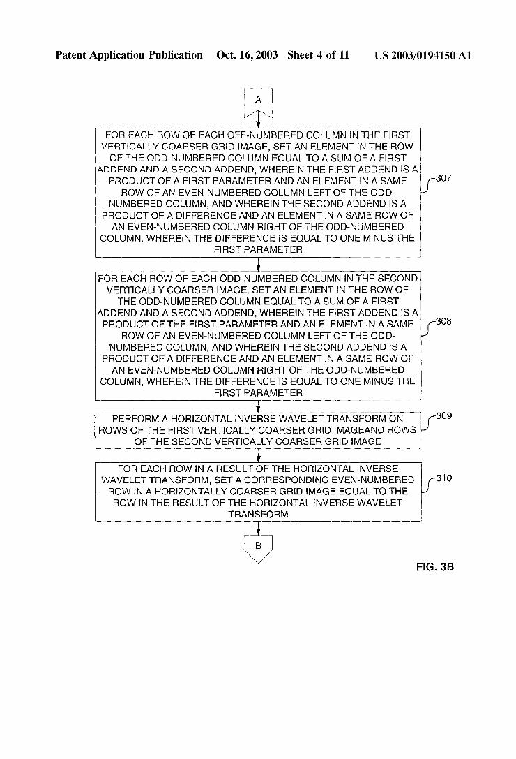
[0059] Then, in process block 307, for each roW of each odd-numbered column (2j+1) in the ?rst vertically coarser grid image (e.g., CL(2j+1,i)), processing logic sets an ele ment in the roW of the odd-numbered column equal to a sum of a ?rst addend and a second addend (erg., CL(2j+1,i)=[u]-) iCL(2j,i)]g+[(1—pj)i)CL(2j+2,i)]=x+y). The ?rst addend is a product of a ?rst parameter and an element in a same roW of an even-numbered column to the left of the odd-numbered column (e.g. x=[u]-)i][CL(2j,i)]). The second addend (y) is a product of a difference (Z) and an element in a same roW of an even-numbered column to the right of
the odd-numbered column (e.g., y=[(1—pj)i)][CL(2j+2,i)]=[Z] [CL(2j+2,i)]). The difference (Z) is equal to one minus the ?rst parameter (e.g. Z=1—pj>i).
[0060] Next, in process block 308, for each roW of each odd-numbered column (2j+1) in the second vertically coarser grid image (e.g., DH(2j+1,i)), processing logic sets an element in the roW of the odd-numbered column equal to a sum of a ?rst addend and a second addend (e.g., DH(2j+ 1,i)=[uJ-)iDH(2j,i)]+[(1—pj>i)DH(2j+2,i)]=x+y). The ?rst addend is a product of the ?rst parameter and an element in a same roW of an even-numbered column to
the left of the odd-numbered column (e. g. x=[uj)i][DH(2j,i)]). The second addend (y) is a product of a difference (Z) and an element in a same roW of an even-numbered column
to the right of the odd-numbered column (e.g. y=[Z][DH(2j+ 2,i)]). The difference (Z) is equal to one minus the ?rst parameter (e.g. Z=1—pj>i).

US 2003/0194150 A1
[0061] Then, in process block 309, processing logic per forms a horizontal inverse Wavelet transform on roWs of the ?rst vertically coarser grid image (e.g., CL(j,i)) and roWs (i) of the second vertically coarser grid image (e.g., DH(j,i)).
[0062] Next, in process block 310, for each roW in a result of the horiZontal inverse Wavelet transform (e.g., iint(j,i)), processing logic sets a corresponding even-num bered roW (2i) in a horizontally coarser grid image (e.g., llNT(j,2i)) equal to the roW in the result of the horiZontal inverse Wavelet transform (e.g., llNT(j,2i)=iint(j,i)).
[0063] Then, in process block 311, for each even-num bered column of each odd-numbered roW (2i+1) in the horiZontally coarser grid image (e.g., IINT(2j,2i+1)), pro cessing logic sets an element in the even-numbered column of the odd-numbered roW equal to a sum of a ?rst addend
and a second addend (e.g., IINT(2j,2i+1)=[v2j>iIINT(2j,2i)]+ [(1—v2]-)i)IINT(2j,2i+2)]=x+y). The ?rst addend is a prod uct of a third parameter (vzji) and an element in a same even-numbered column of an even-numbered roW above the odd-numbered roW (e.g. x=[v2]->i][IINT(2j,2i)]). The sec ond addend (y) is a product of a difference (Z) and an element in a same even-numbered column of an even
numbered roW beloW the odd-numbered roW (e.g., y=[Z] [IINT(2j,2i+2)]). The difference (Z) is equal to one minus the third parameter (e.g., Z=1—V2]-)i). [0064] Finally, in process block 312, for each odd-num bered column (2j+1) of each odd-numbered roW (2i+1) in the horiZontally coarser grid image (e.g., IINT(2j+1,2i+1)), processing logic sets an element in the odd-numbered col umn of the odd-numbered roW equal to a sum of a ?rst
addend and a second addend (e.g., IINT(2j+1,2i+1)=[v2]-) iIINT(2j+1,2i)]+[(1—v2j)i)IINT(2j+1,2i+2)]=x+y). The ?rst addend is a product of the third parameter (vzji) and an element in a same odd-numbered column (2j+1) of an even-numbered roW above the odd-numbered roW (e.g. x=[v2]-)i][IINT(2j+1,2i)]). The second addend (y) is a product of a difference (Z) and an element in a same odd-numbered column (2j+1) of an even-numbered roW beloW the odd numbered roW (e.g., y=[Z][IINT(2j+1,2i+2)]). The difference (Z) is equal to one minus the third parameter (e.g., Z=1—V2]-)i).
[0065] In one embodiment, processing logic clips the resulting image back to a range, shoWn in process block 313. Process block 314 illustrates one embodiment of the clip ping in Which each element in the resulting image having a value beloW the range being set to a loWest value in the range and each element in the resulting image having a value above the range being set to a highest value in the range. Thus, in one embodiment, the range is a range of 256 shades of gray. In another embodiment, the range is a range of a greater number of shades of gray; for example, 65,536 shades. In yet another embodiment, the image is a color image having three ranges for hues of red, green, and blue, respectively. Each of these ranges is similarly clipped. Thus, the desired image palette is maintained throughout the interpolation. [0066] In one embodiment, the Wavelet coef?cients are redundant Haar Wavelet coef?cients.
[0067] In one embodiment, the ?rst parameter and the third parameter (vzji) are set to 0.5.
[0068] In one embodiment, if a condition (k‘) is satis?ed, the ?rst parameter is a numerator divided by a denomi
Oct. 16, 2003
nator (e~g~> ,uj,i=[|dLH+HH(.l+1>i)|p]/[|dLH+HH(.l_1>i)|p+|dLH+ +1,i)|p]=x/y). The numerator is a ?rst absolute value exponentially raised to a poWer of a second parameter
(e.g., x=[|dLH+HH(j+1,i)|][p]=|x‘|p). The ?rst absolute value is an absolute value of a ?rst element The ?rst
element (x‘) is an element in a column (j+1) and roW in the ?fth coef?cient matrix (e.g., x‘=dLH+HH(j+1,i)). The column (j+1) in the ?fth coefficient matrix is a column right of a column in the ?fth coefficient matrix that corresponds to an even-numbered column left of the odd-numbered column (2j+1) in the ?rst vertically coarser grid image (and also the odd-numbered column (2j+1) in the second verti cally coarser grid image). The roW in the ?fth coef?cient matrix corresponds to the roW of the odd-numbered column in the ?rst vertically coarser grid image (and also the roW of the odd-numbered column in the second vertically coarser grid image). The denominator (y) is a sum of an addend (Z) and the numerator (e.g., y=[|dLH+HH(j—1,i)|p]+ [|dLH+HH(j+1,1)|p]=Z+X). The addend (Z) is a second absolute value (|Z‘|) exponentially raised to the oWer of the second parameter (e.g., Z=[|dLH+HH(j—1,1)|][p =|Z‘|p). The second absolute value (|Z‘|) is an absolute value of a second element (Z‘). The second element (Z‘) is an element in a column (j-l) and roW in the ?fth coef?cient matrix (e.g., Z‘=dLH+HH(j— 1,i)). The column (j-l) in the ?fth coef?cient matrix is a column left of a column in the ?fth coef?cient matrix that corresponds to an even-numbered column left of the odd-numbered column (2j+1) in the ?rst vertically coarser grid image (and also the odd-numbered column (2j+1) in the second vertically coarser grid image). The roW in the ?fth coef?cient matrix corresponds to the roW of the odd numbered column in the ?rst vertically coarser grid image (and also the roW of the odd-numbered column in the second vertically coarser grid image).
[0069] In one embodiment, the second parameter is equal to one.
[0070] In one embodiment, the condition (k‘) is satis?ed if an absolute value is greater than a threshold (e.g., |dLH+HH(j, i)|>e) and the denominator is not equal to Zero (e.g., |dLH+ HHG—1,1)|p+|dLH+HH(j+1,I)|p#0) and a product is not less than Zero (e.g., [dLH+HH(j—1,i)][dLH+HH(j+1,i)]§0). The absolute value is an absolute value of a third element. The third element is an element in a column and roW in the ?fth coefficient matrix (e.g., dLH+HH(j,i)). The column in the ?fth coef?cient matrix corresponds to an even-numbered column left of the odd-numbered column (2j+1) in the ?rst vertically coarser grid image (and also the odd-num bered column (2j+1) in the second vertically coarser grid image). The roW in the ?fth coef?cient matrix corre sponds to the roW of the odd-numbered column in the ?rst vertically coarser grid image (and also the roW of the odd-numbered column in the second vertically coarser grid image). The product is a product of the ?rst element and the second element (e.g., [x‘][Z‘]=[dLH+HH(j+1,i)][dLH+HH(j—1, 01) [0071] In one embodiment, the ?rst parameter is set to one if the absolute value is greater than the threshold (e. g., |dLH+HH(j,i)|>e) and the denominator is equal to Zero (e.g.,
to one if the absolute value is greater than the threshold (e. g., |dLH+HH(j,i)|>e) and the product is less than Zero (e. g.,

US 2003/0194150 A1
[0073] In one embodiment, if a condition (k‘) is satis?ed, the third parameter (vzji) is a numerator divided by a denominator (e.g., v2j>i=[|DH(2j,i+1)|p]/[|DH(2j,i—1)|p+ |DH(2j,i+1)|P]=x/y), Where k‘ is different than the parameter k mentioned above in the prior art. The numerator is a ?rst absolute value exponentially raised to a poWer of a second parameter (e.g., x=[|DH(2j,i+1)|][p]=|x‘|p). The ?rst absolute value is an absolute value of a ?rst element (x‘). The ?rst element (x‘) is an element in a roW (i+1) and even-numbered column in the second vertically coarser grid image (e.g., x‘=DH(2j,i+1)). The roW (i+1) in the second vertically coarser grid image is a roW beloW a roW in the second vertically coarser grid image that corresponds to an even-numbered roW (2i) above the odd-numbered roW (2i+ 1) in the horiZontally coarser grid image. The even-num bered column in the second vertically coarser grid image corresponds to the even-numbered column of the odd numbered roW in the horiZontally coarser grid image. The denominator (y) is a sum of an addend (Z) and the numerator (e.g., y=[|DH(2j,i—1)|p]+[|DH(2j,i+1)|p]=Z+x). The addend (Z) is a second absolute value (|Z‘|) exponentially raised to the poWer of the second parameter (e.g., Z=[|DH(2j,1—1)|][p]= |Z‘|P). The second absolute value (|Z‘|) is an absolute value of a second element (2‘). The second element (Z‘) is an element in a roW (i— 1) and even-numbered column in the second vertically coarser grid image (e.g., Z‘=DH(2j ,i—1)). The roW (i—1) in the second vertically coarser grid image is a roW above a roW in the second vertically coarser grid image that corresponds to an even-numbered roW (2i) above the odd-numbered roW (2i+1) in the horiZontally coarser grid image. The even-numbered column in the second ver tically coarser grid image corresponds to the even-numbered column of the odd-numbered roW in the horiZontally coarser grid image.
[0074] In one embodiment, the condition (k‘) is satis?ed if an absolute value is greater than a threshold (e.g., |DH(2j, i)|>e) and the denominator is not equal to Zero (e.g., |DH(2j, i—1)|p+|DH(2j,i+1)|p#0) and a product is not less than Zero (e.g., [DH(2j,i—1)][DH(2j,i+1)]Z0). The absolute value is an absolute value of a third element. The third element is an element in a roW and even-numbered column in the second vertically coarser grid image (e.g., DH(2j,i)). The roW in the second vertically coarser grid image corre sponds to an even-numbered roW (2i) above the odd-num bered roW (2i+1) in the horiZontally coarser grid image. The even-numbered column in the second vertically coarser grid image corresponds to the even-numbered column of the odd-numbered roW in the horiZontally coarser grid image. The product is a product of the ?rst element and the second element (e.g., [x‘][Z‘]=[DH(2j,i—1)][DH(2j,i+1)]).
[0075] In one embodiment, the third parameter (vzji) is set to one if the absolute value is greater than the threshold (e.g., |DH(2j,i)|>e) and the denominator is not equal to Zero (e.g., |DH(2j,i—1)|P+|DH(2j,i+1)|P¢0).
[0076] In one embodiment, the third parameter (V211) is set to one if the absolute value is greater than the threshold (e.g., |DH(2j,i)|>e) and the product is not less than Zero (e.g., tDH(2j,1-1)1[DH(214+1)120)
[0077] The threshold (6) may prevent noise pixels, includ ing halftone noise pixels, from being treated as strong edges. In smooth regions Where detail coef?cients are Zero, the interpolation may reduce to linear interpolation.
Oct. 16, 2003
[0078] FIG. 4 is a block diagram of one embodiment of an apparatus to perform interpolation embedded Within an inverse Wavelet transform. Referring to FIG. 4, the appa ratus 400 comprises a receiving unit 401 to receive an image given in Wavelet coef?cients and a processing unit 402 coupled With the receiving unit 401. The processing unit 402 performs the functionality described above. In one embodi ment, the apparatus shoWn in FIG. 4 comprises a multi function machine.
[0079] FIG. 5 is a schematic diagram illustrating an example of adaptive nonlinear image enlargement using Wavelet transform coef?cients compared With standard bicu bic interpolation according to one embodiment. Image 501 Was generated using standard bicubic interpolation. Image 502 Was generated using Wavelet-based nonlinear interpo lation. In one embodiment, the pixel differences in the prior art algorithm are equivalent to Haar Wavelet coef?cients of a redundant Wavelet transform. In contrast to the prior art algorithm, in one embodiment, the technique set forth herein using a redundant Haar transform interpolates a perfect step edge “exactly,” i.e., the interpolated signal has also a perfect step edge.
[0080] FIG. 6 is a How diagram illustrating one embodi ment of a process for interpolating a step edge. In one embodiment, an image having a perfect step edge is received in process block 601, and the perfect step edge is interpo lated exactly While the image is enlarged in process block 602.
[0081] In one embodiment, the technique is also applied using redundant Wavelet transform coef?cients for arbitrary Wavelet types. It is also used for maximal decimated Wavelet transforms and complex Wavelet transforms.
[0082] In one embodiment, the technique is extended to include information from various levels of the Wavelet decomposition by, e.g., using Wavelet coef?cients from larger scales for computation of the parameters p and v.
[0083] In combination With a Wavelet sharpening and smoothing (“WSS”) technique, the enlargement may be performed after denoising by thresholding and sharpening/ smoothing by resealing of Wavelet coef?cients. For more information on WSS, see US. patent application Ser. No. 09/467,544, entitled “Multiscale Sharpening and Smoothing With Wavelets” ?led on Dec. 10, 1999, and assigned to the corporate assignee of the present invention.
[0084] In one embodiment, for the purpose of enlargement of JPEG2000 or similar compressed images, the technique described above is incorporated into the last level of the inverse Wavelet transform on the decoder side.
[0085] Applications [0086] There are a number of additional applications in Which the adaptive non-linear image enlargement described herein may be advantageous. For example, adaptive non linear image enlargement may be used in the enlargement process in a digital copier processing path. Such a system is shoWn in FIG. 7. Referring to FIG. 7, a forWard redundant Wavelet transform 701 is applied to an image. The Wavelet transform 701 may be applied M times to the image, such that there are M levels, Where M is greater than 1. After applying the forWard redundant Wavelet transform 701, noise removal, text sharpening, halftone smoothing is

US 2003/0194150 A1
applied to the coef?cients at image processor 702. After such processing, an inverse redundant Wavelet transform 703 is applied to the processed coef?cients. In one embodiment, the inverse redundant Wavelet transform 703 is applied M-1 times so that there are M-1 levels. After applying the inverse redundant Wavelet transform 703, an enlarger 704 performs the enlargement process described herein. Note that each of these blocks may be implemented in softWare, hardWare or a combination of both.
[0087] The adaptive non-linear image enlargement may be utiliZed in an upsampling process in Which upsampling is done for printing at a higher dpi, e.g., images scanned at 600 dpi and printed at 1200 dpi. Such a system is shoWn in FIG. 8. Referring to FIG. 8, a one level redundant Wavelet transform 801 is applied to a received digital image at a speci?c dpi resolution R (800). The coef?cients are output to enlarger 802 Which performs the enlargement process described herein. After enlargement, processing is per formed for printing at 2R dpi by image processor 803. The processing may include gamma correction, halftoning, etc. The output 804 is a processed image. In this manner, the adaptive non-linear image enlargement process is used to repair the loWer resolution image for high resolution print ing. Note that each processing element in FIG. 8 may be implemented in hardWare, softWare, or a combination of both.
[0088] Other applications include the use of the adaptive non-linear image enlargement technique described herein for the enlargement of JPEG2000 images. This might require an addition to a JPEG decoder to compensate for the non-linear image enlargement. Another application is digital cameras. Speci?cally, the adaptive non-linear image enlargement process may be performed for demosaicing in a digital camera.
[0089] An Exemplary Computer System
[0090] FIG. 9 is a block diagram of an exemplary com puter system that may perform one or more of the operations described herein. Referring to FIG. 9, computer system 900 may comprise an exemplary client 950 or server 900 com puter system. Computer system 900 comprises a communi cation mechanism or bus 911 for communicating informa tion, and a processor 912 coupled With bus 911 for processing information. Processor 912 includes a micropro cessor, but is not limited to a microprocessor, such as, for example, PentiumTM, PoWerPCTM, etc.
[0091] System 900 further comprises a random access memory (RAM), or other dynamic storage device 904 (referred to as main memory) coupled to bus 911 for storing information and instructions to be executed by processor 912. Main memory 904 also may be used for storing temporary variables or other intermediate information dur ing execution of instructions by processor 912.
[0092] Computer system 900 also comprises a read only memory (ROM) and/or other static storage device 906 coupled to bus 911 for storing static information and instruc tions for processor 912, and a data storage device 907, such as a magnetic disk or optical disk and its corresponding disk drive. Data storage device 907 is coupled to bus 911 for storing information and instructions.
[0093] Computer system 900 may further be coupled to a display device 921, such as a cathode ray tube (CRT) or
Oct. 16, 2003
liquid crystal display (LCD), coupled to bus 911 for dis playing information to a computer user. An alphanumeric input device 922, including alphanumeric and other keys, may also be coupled to bus 911 for communicating infor mation and command selections to processor 912. An addi tional user input device is cursor control 923, such as a mouse, trackball, trackpad, stylus, or cursor direction keys, coupled to bus 911 for communicating direction information and command selections to processor 912, and for control ling cursor movement on display 921.
[0094] Another device that may be coupled to bus 911 is hard copy device 924, Which may be used for printing instructions, data, or other information on a medium such as paper, ?lm, or similar types of media. Furthermore, a sound recording and playback device, such as a speaker and/or microphone may optionally be coupled to bus 911 for audio interfacing With computer system 900. Another device that may be coupled to bus 911 is a Wired/Wireless communica tion capability 925 to communication to a phone or handheld palm device.
[0095] Note that any or all of the components of system 900 and associated hardWare may be used in the present invention. HoWever, it can be appreciated that other con ?gurations of the computer system may include some or all of the devices.
[0096] Whereas many alterations and modi?cations of the present invention Will no doubt become apparent to a person of ordinary skill in the art after having read the foregoing description, it is to be understood that any particular embodi ment shoWn and described by Way of illustration is in no Way intended to be considered limiting. Therefore, refer ences to details of various embodiments are not intended to limit the scope of the claims Which in themselves recite only those features regarded as essential to the invention.
What is claimed is: 1. A method comprising:
receiving a Wavelet representation of an image, the Wave let representation comprising Wavelet coef?cients; and
performing localiZed adaptive interpolation on the Wave let coef?cients in the Wavelet domain.
2. The method de?ned in claim 1 further comprising performing upsampling using adaptive ?lters on Wavelet coef?cients.
3. The method de?ned in claim 2 Wherein ?lter coef? cients of the adaptive ?lters are computed from Wavelet coef?cients.
4. The method de?ned in claim 1 Wherein performing localiZed adaptive interpolation comprises performing linear interpolation on the Wavelet coefficients.
5. The method de?ned in claim 1 Wherein performing localiZed adaptive interpolation comprises performing inter polation on at least one of the Wavelet coef?cients if the at least one coef?cients of the Wavelet coef?cients meets a condition.
6. The method de?ned in claim 5 Wherein the condition is Whether the at least coef?cient is greater than a threshold.
7. The method de?ned in claim 6 Wherein the threshold represents a noise level in the image.
8. The method de?ned in claim 5 Wherein the condition is Whether the at least one coefficient belongs to an area in the image.

US 2003/0194150 A1
9. The method de?ned in claim 8 Wherein the area comprises a halftone area in the image.
10. The method de?ned in claim 9 further comprising a classi?er determining Whether the at least one Wavelet coef?cient is in the halftone area of the image.
11. The method de?ned in claim 8 Wherein the area comprises a teXt area in the image.
12. The method de?ned in claim 11 further comprising a classi?er determining Whether the at least one Wavelet coef?cient is in the teXt area of the image.
13. The method de?ned in claim 8 Wherein the area comprises a region-of-interest.
14. The method de?ned in claim 13 Wherein the region of-interest is a JPEG 2000 region of interest.
15. The method de?ned in claim 8 Wherein the area comprises a JPEG 2000 layer.
16. The method de?ned in claim 1 further comprising performing upsampling using coef?cient dependent interpo lation.
17. The method de?ned in claim 1 Wherein performing localiZed adaptive interpolation on the Wavelet coefficients in the Wavelet domain comprises:
applying a vertical inverse transform on columns of loWpass coef?cients and detail coefficients to produce ?rst and second sets of results;
placing the ?rst and second sets of results in ?rst and second grid images, respectively, in Which every other column in each of the ?rst and second grid images does not include values;
performing interpolation using an interpolation technique on values in columns in the ?rst and second grid images to create values for columns in the ?rst and second grid images that do not include values;
applying a horiZontal inverse transform on roWs of the ?rst and second grid images to produce second and third sets of results;
placing the third and fourth sets of results in third and fourth grid images, respectively, in Which every other roW in each of the third and fourth grid images does not include values; and
performing an interpolation using the interpolation tech nique on values in roWs in the third and fourth grid images to create values for roWs in the third and fourth grid images that do not include values.
18. The method de?ned in claim 17 Wherein the interpo lation technique comprises a nonlinear interpolation.
19. The method de?ned in claim 17 further comprising clipping resulting values to a predetermined range.
20. The method de?ned in claim 1 Wherein performing localiZed adaptive interpolation on the Wavelet coefficients in the Wavelet domain comprises:
applying a horiZontal vertical inverse transform on col umns of loWpass coef?cients and detail coef?cients to produce ?rst and second sets of results;
placing the ?rst and second sets of results in ?rst and second grid images, respectively, in Which every other column in each of the ?rst and second grid images does not include values;
performing interpolation using an interpolation technique on values in columns in the ?rst and second grid images
Oct. 16, 2003
to create values for columns in the ?rst and second grid images that do not include values;
applying a vertical inverse transform on roWs of the ?rst and second grid images to produce second and third sets of results;
placing the third and fourth sets of results in third and fourth grid images, respectively, in Which every other roW in each of the third and fourth grid images does not include values; and
performing an interpolation using the interpolation tech nique on values in roWs in the third and fourth grid images to create values for roWs in the third and fourth grid images that do not include values.
21. An apparatus comprising:
means for a Wavelet representation of an image, the Wavelet representation a means for Wavelet coef? cients; and
means for localiZed adaptive interpolation on the Wavelet coef?cients in the Wavelet domain.
22. The apparatus de?ned in claim 21 further comprising means for performing upsampling using adaptive ?lters on Wavelet coef?cients.
23. The apparatus de?ned in claim 22 Wherein ?lter coef?cients of the adaptive ?lters are computed from Wave let coef?cients.
24. The apparatus de?ned in claim 21 Wherein the means for performing localiZed adaptive interpolation comprises means for performing linear interpolation on the Wavelet coef?cients.
25. The apparatus de?ned in claim 21 Wherein the means for performing localiZed adaptive interpolation comprises means for performing interpolation on at least one of the Wavelet coef?cients if the at least one coef?cients of the Wavelet coef?cients meets a condition.
26. The apparatus de?ned in claim 25 Wherein the con dition is Whether the at least coefficient is greater than a threshold.
27. The apparatus de?ned in claim 26 Wherein the thresh old represents a noise level in the image.
28. The apparatus de?ned in claim 25 Wherein the con dition is Whether the at least one coef?cient belongs to an area in the image.
29. The apparatus de?ned in claim 28 Wherein the area comprises a halftone area in the image.
30. The apparatus de?ned in claim 29 further comprising a classi?er to determine Whether the at least one Wavelet coef?cient is in the halftone area of the image.
31. The apparatus de?ned in claim 28 Wherein the area comprises a teXt area in the image.
32. The apparatus de?ned in claim 31 further comprising a classi?er to determine Whether the at least one Wavelet coef?cient is in the teXt area of the image.
33. The apparatus de?ned in claim 28 Wherein the area comprises a region-of-interest.
34. The apparatus de?ned in claim 33 Wherein the region of-interest is a JPEG 2000 region of interest.
35. The apparatus de?ned in claim 28 Wherein the area comprises a JPEG 2000 layer.
36. The apparatus de?ned in claim 21 further comprising means for performing upsampling using coef?cients depen dent interpolation.
