addendum 03 to the dlr group - florida gateway college
TRANSCRIPT

ADDENDUM 03 Page - 1
ADDENDUM 03 TO THE DLR Group
100 East Pine Street Suite 404
Orlando, FL 32801 Phone 407-648-1331
Fax 407-648-1433
PROJECT MANUAL AND DRAWINGS FOR
January 8, 2021 FLORIDA GATEWAY COLLEGE NEW STEM FACILITY 149 SE COLLEGE PL. LAKE CITY, FLORIDA 32025 DLR Group Project No. 36-17116-00 FOR SEPARATE CONTRACTS NOTICE TO BIDDERS: The Question and Answer Log is attached for bidders’ reference. NOTICE TO BIDDERS: The Project Manual and Drawings for the above referenced project are hereby amended as follows:
PROJECT MANUAL
ITEM NO. 1 TABLE OF CONTENTS a. Division 00: Delete “004321 ALLOWANCE FORM”.
b. Division 00: Delete “005100 NOTICE OF AWARD”.
c. Division 00: Delete “006000 PROJECT FORMS”.
d. Division 07: Add the following:
“074800 EXTERIOR WALL CONTINUOUS INSULATION SYSTEM
e. Division 13: Delete Division 13 designation in its entirety and substitute the following:
“DIVISION 13 – SPECIAL CONSTRUCTION
133435 FABRICATED WALKWAY COVERS”
ITEM NO. 2 SECTION 004113 – BID FORM a. Delete Bid Form in its entirety and substitute Section 004113 attached to Addendum 03
dated January 8, 2021.
ITEM NO. 3 SECTION 004321 – ALLOWANCE FORM a. Delete Section 004321 in its entirety.
ADDENDUM 03 Page - 2
ITEM NO. 4 SECTION 004393 – BID SUBMITTAL CHECKLIST a. Delete Section 004393 in its entirety and substitute Section 004393 attached to Addendum
03 dated January 8, 2021.
ITEM NO. 5 SECTION 005100 – NOTICE OF AWARD a. Delete Section 005100 in its entirety.
ITEM NO. 6 SECTION 006000 – PROJECT FORMS a. Delete Section 006000 in its entirety.
ITEM NO. 7 SECTION 012100 – ALLOWANCES a. Delete Section 012100 in its entirety and substitute Section 012100 attached to Addendum
03 dated January 8, 2021.
ITEM NO. 8 SECTION 019113 – GENERAL COMMISSIONING REQUIREMENTS a. Delete Section 019113 in its entirety and substitute Section 019113 attached to Addendum
03 dated January 8, 2021. Sample percentages revised and lab elements indicated for clarification. Allowance required by the general contractor for the Independent Commissioning Agent for specified code commissioning.
ITEM NO. 9 SECTION 074800 – EXTERIOR WALL CONTINUOUS INSULATION SYSTEM a. Add Section 074800 attached to Addendum 03 dated January 8, 2021.
ITEM NO. 10 SECTION 133435 – FABRICATED WALKWAY COVERS a. Add Section 133435 attached to Addendum 03 dated January 8, 2021.
ITEM NO. 11 SECTION 275113 – PUBLIC ADDRESS/BACKGROUND MUSIC SYSTEM a. Delete Section 275113 in its entirety and substitute Section 275113 attached to Addendum
03 dated January 8, 2021. Speaker type 3 indicated for clarification. Spare speakers’ quantity indicated for clarification.
ITEM NO. 12 SECTION 321410 – PAVERS a. Delete Section 321410 in its entirety and substitute Section 321410 attached to Addendum
03 dated January 8, 2021.
DRAWINGS
ITEM NO. 13 SHEET A3.1 – REFLECTED CEILING PLAN, FIRST LEVEL a. Revised General Notes to clarify extent of paint for exposed structure.
ITEM NO. 14 SHEET A3.2 – REFLECTED CEILING PLAN, SECOND LEVEL a. Revised General Notes to clarify extent of paint for exposed structure.
ITEM NO. 15 SHEET A4.1 – ROOF PLAN AND DETAILS a. Revised roof plan to clarify tapered insulation locations.
ITEM NO. 16 SHEET A8.3 – VERTICAL CIRCULATION a. Revised annotations to call out bentonite waterproofing.
ITEM NO. 17 SHEET A9.1 – DOOR AND FRAME SCHEDULE & TYPES a. Revised Door Frame Type for E103.
ITEM NO. 18 SHEET A10.2 – SECTION DETAILS a. Added roller shades to window headers.

ADDENDUM 03 Page - 3
ITEM NO. 19 SHEET A10.5 – GENERAL BUILDING DETAILS a. Revised mop sink detail.
b. Added 3D Typical Parapet detail.
ITEM NO. 20 SHEET A12.0 – FINISH SCHEDULE a. Revised Material List and Room Finish Schedule.
ITEM NO. 21 SHEET A13.1 – FINISH FLOOR PLAN, FIRST LEVEL a. Updated finish tags at Janitor Closet.
ITEM NO. 22 SHEET A13.2 – FINISH FLOOR PLAN, SECOND LEVEL a. Updated finish tags at Janitor Closet.
ITEM NO. 23 SHEET M1.1 – MECHANICAL FLOOR PLAN – FIRST LEVEL a. REVISED: General Notes #3, 4, 5 for Fume Hood, Laminar Flow Hood, and BSC
Certification requirements indicated for clarification.
ITEM NO. 24 SHEET E2.1 – POWER FLOOR PLAN – FIRST LEVEL a. REVISED: Power for AV rack in in Rm 120 indicated for clarification.
ITEM NO. 25 SHEET E7.2 – PANEL SCHEDULES a. REVISED: Panel schedule updated for above AV rack in in Rm 120 for clarification.
ITEM NO. 26 SHEET T1.0 – TECHNOLOGY SITE PLAN a. REVISED: Clarified quantity of fiber optic microducts per Pre-Bid RFI responses issued,
for clarification.
ITEM NO. 27 SHEET T1.1 – VOICE DATA FLOOR PLAN – FIRST LEVEL a. Clarified site plan conduits for clarification. (Note: Contractor shall refer to AV drawings for
Data required at each AV rack, typical).
ITEM NO. 28 SHEET T2.1 – AUDIO VIDEO & SECURITY FLOOR PLAN – FIRST LEVEL a. Indicated S3 speakers in corridors for clarification. Indicated AV rack at room 120 for
clarification.
ITEM NO. 29 SHEET T2.2 – AUDIO VIDEO & SECURITY FLOOR PLAN – SECOND LEVEL a. Indicated S3 speakers in corridors for clarification.
ITEM NO. 30 SHEET T6.1 – TECHNOLOGY ELEVATIONS, RISERS AND DETAILS a. Fiber Riser Demolition detail was deleted. Fiber Riser diagram revised to reflect actual
conditions on site (Building already demolished), added SM fiber to fiber backbone between 1st and 2nd floors and added qty. of fiber strands for pull back to campus main computer room, per pre-bid RFI response issued, for clarification.
ITEM NO. 31 SHEET T6.5 – AV LINE DIAGRAMS a. REVISED: Detail 2 revised for clarification. Detail 1 revised for clarification.
END OF ADDENDUM 03

FGC New STEM Facility
Question and Answer Log1/8/2021
No. Spec/Sheet Question/Clarification Date By Response By ADD
1 Do you have a potential start date for this project? 12/15/2020 Foresight College is targeting a February board approval of the bids and want construction to start ASAP.
DLR Group 1
2 012100 Allowances is not in the spec book, will this be provided? 12/15/2020 Foresight This section will be provided as an Addendum. DLR Group 1
3 Do you have an RFI deadline? 12/15/2020 Foresight In the Div 1 specs there’s a date of 01/07/2021 by 12pm to submit questions by.
DLR Group 1
4 Once RFI’s come in, do you have a specific form, or we can use our own RFI Log to send your way? 12/15/2020 Foresight This is the format for the Pre-Bid Q&A. Two addendums will be issued. DLR Group
5 Are you the contact to send any RFI’s? 12/15/2020 Foresight Yes, but copy Misty Taylor([email protected]), (Danny Kail ([email protected]) and Arlenne Gil ([email protected]) as well.
DLR Group 1
6 Can you clarify the lab casework is in our scope of work and not purchased by the Owner. 12/16/2020 Foresight
Per General Notes on drawings (A2.1), Owner will procure the Lab Casework and Equipment indicated as Owner Furnished, Contractor Installed. Contractor should request Casework and Equipment shops from the owner for coordination with other subs. Updated in Addendum 02: Lab Casework/Casework will be Owner Furnished and non-mechaincally installed by Owner. General Contractor is responsible for all Final Mechanical, Electrical, and Plumbing Connections.
CRB 1
7 Do you have specifications on the lab casework? 12/16/2020 Foresight See Response to note 6. CRB 1
8A1.1 & A1.2 have Note #3 for "Automatic vertically retractable acoustical wall." Location not shown on drawings, can you please clarify? 12/17/2020 Foresight
There is no Automatic vertically retractable wall. This note should have been deleted.
DLR Group 1
9Please provide specs for 064000 – Wood veneer casework, 123200 – Plam casework as well as all the Lab equipment such as Fume Hoods, peg boards, google cabinets, flammable & acid storage cabinets, etc.
12/17/2020 Foresight
064116 Plastic Laminate Clad Architectural Cabinets spec section has been provided in Addendum 01. Updated Addendum 02: Lab Casework, Fume Hoods, Peg Boards, Goggle Cabinets, Flamable& ACid Storage Cabinets will be Owner Furnished and non-mechaincally installed by Owner. General Contractor is responsible for all Final Mechanical, Electrical, and Plumbing Connections.
DLR Group 1
10 For controls, are KMC, JIC, or Automated approved equals?12/17/2020 Foresight
TLC has confirmed with FGC -- No, KMC, JIC and JCI are not approved alternate building automation vendors for this project. Please provide BAS controls per specifications.
TLC Engineering 1
11 107113Are the aluminum canopies above the south and west entrances to be the C.R. Laurence sunshades per spec section 107113? If not, where are these sunshades located and are there any pre approved manufacturers for these aluminum canopies? 12/22/2020 Scherer Construction
Spec Section 107113 Exterior Sunshades has been removed. We no longer have Sunshades on the project.
DLR Group 2
12Is there a basis of design for the Door 108A Fire Shutter? 12/22/2020 Scherer Construction
Spec Section 083324 Overhead Coiling Fire Doors have been added. In addition, details have been added to sheet A9.3.
DLR Group 2
13 A2.3A2.3 lists the Cold Storage as CFCI. However, the remarks state by Nycom. If the Cold Storage is to be CFCI. Can you please provide a specification for pricing? 12/22/2020 Scherer Construction
CDS-01 COLD ROOM should read OFCI. Cold Room to be Owner Furnished and Non-mechanically installed by Owner. General Contractor is responsible for all Final Mechanical, Electrical and Plumbing Connections.
CRB 2
14Is there a Survey available? If so, can you please forward it to us? 12/22/2020 Scherer Construction
A CAD file of the survey has been provided in Addendum 02 NFPS 2
15The Bid Submittal Checklist was not included in the specifications. Can you please forward it to us? 12/22/2020 Scherer Construction
004393 Bid Submittal Checklist added along with Attachment 10. DLR Group 2
16 A1.1, A1.2A1.1 & A1.2 legend notes are not populated on the plans. Can you please clarify where these items occur? 12/22/2020 Scherer Construction
In Addendum 01, notes on A1.1 and A1.2 have been adjusted. DLR Group 1
17 Civil - some existing contour lines do not have elevation labels. Please provide elevations.12/22/2020 Scherer Construction
See provided survey. NFPS (Civil) does not modify, nor add to a certified survey. NFPS 2
18The parking lot that the new sidewalk ties in to on the South side of the building does not have any elevation information. Please provide elevation information. 12/22/2020 Scherer Construction
See detail 7 on sheet C8. NFPS 2
19 Please provide elevation information on the sidewalk where it ties in to the existing parking lot.12/22/2020 Scherer Construction
See detail 7 on sheet C8. NFPS 2
20 A2000 pvc is not readily available in our area. Is SDR35 PVC or HDPE acceptable as an alternate?12/22/2020 Scherer Construction
SDR26 is an acceptable alternative. Limited pipe cover requires more durable pipe.
NFPS 2
21There are six locations where 6” storm pipe is stubbed out on the North and South side of the building. Are these for internal roof drains or downspouts? If downspouts please provide a connection detail.
12/22/2020 Scherer Construction
TLC Response: The primary storm drains (indivated on P1.1) are indictated below grade, and are to be hard connected to storm system, as Civil drawings should be showing the six storm connections. (TLC notes that each roof drain, overflow storm drains have down spout nozzles, as indicated on the level 1 and level 2 as "DSN-1."
TLC Engineering 2
22The Chilled Water line layout does not match between drawings C6.0 and M1.1. If M1.1 is correct layout, please provide a distance to existing tie-in.
12/22/2020 Scherer Construction
TLC Response: Reference note 5/M1.1 requires the contractor to filed verify the existing CHW Mains location and final pipe routing. (Design drawings are design intent, not shop drawings.) TLC also notes that the pre-engineered underground piping is to be a pre-engineered (delegated design) piping system, coordinated with all utilities and existing conditions, refer to Reference note 15/M1.1.
TLC Engineering 2
Page 1 of 11
FGC New STEM Facility
Question and Answer Log1/8/2021
No. Spec/Sheet Question/Clarification Date By Response By ADD
23Is there a specified product/manufacturer for exterior Factory Finished Metal Panels MP-01 and MP-02? 12/22/2020 Scherer Construction
Spec Section 074213, 2.2.B and 2.2.C specifies MP-01 and MP-02. DLR Group 2
24Landscape/Hardscape
Please provide a manufacturer for brick paver, supplier is unaware of a 4x8x4 paver with zero bevel. 12/22/2020 Scherer Construction
Pavers approved to be Belgrade "Holland Stone", 4x8x2 3/8" (60mm). These are in lieu of the 4x8x4 (100mm) size. Refer to Section 321410-Pavers-Addendum 2 - 01-05-2021. Specified brick link:
http://www.belgard.com/products/pavers/holland-stone
J. Randolph 2
25
Please confirm that concrete sand setting bed (per ICPI guidelines) is acceptable substitute to crush concrete setting bed. Manufacturers adhere to ICPI guidelines and a crush concrete will void warranties. 12/22/2020 Scherer Construction
Spec Section 321410 Pavers, 2.1 Bedding and Joint Sands provides direction for sand setting bed.
J. Randolph 2
26 095100 /A12.0
The Acoustical Ceilings specifications, Section 95100, page 3, paragraph 2.1, line A1, calls out the manufacturers of the ceiling tile and says to “ See material list on sheet A12.0 “, but the Finish Legend, on sheet A12.0, calls out the size and the Type of ceiling tiles to be used, but it does not clarify as to whether or not the ceiling panels are a square edge or a reveal edge. Please clarify. 12/22/2020 Scherer Construction
Tegular Edge throughout. Square Edge in Restroom. Finish Legend on A12.0 has been updated.
DLR Group 2
27
230900 The specification for the HVAC controls lists Siemens or equal. Please confirm if KMC, JIC, or Automated are approved equals. 12/24/2020 Scorpio
TLC has confirmed with FGC -- No, KMC, JIC and JCI are not approved alternate building automation vendors for this project. Please provide BAS controls per specifications. (Duplicate of Pre-Bid RFI #10)
TLC Engineering 1
28A9.1 The door schedule on A9.1 shows a coiling fire door but there is no specification, manufacturer, or
model #. Please provide what coiling fire door is required.12/24/2020 Scorpio See Response to item 12. DLR Group 2
29102800 Please confirm if any of the toilet accessories are OFCI.
12/24/2020 ScorpioAll toilet accessories are CPCI. Owner will not be providing any of these items. Basis of Design is the desired standard for the Owner.
DLR Group/FGC 2
30
A2.3 Please provide the manufacturer and model for the walk-in cooler.
12/24/2020 ScorpioCDS-01 COLD ROOM should read OFCI. Cold Room to be Owner Furnished and Non-mechanically installed by Owner. General Contractor is responsible for all Final Mechanical, Electrical and Plumbing Connections.
CRB/Nycom 2
31 Is there an existing access control system on campus that this building will tie into? 12/24/2020 Scorpio Yes. Connection will be via fiber that is already indicated. TLC Engineering 2
32
Please provide a specification for the casework that is CFCI.
12/24/2020 Scorpio
Lab Casework/Casework will be Owner Furnished and non-mechaincally installed by Owner. General Contractor is responsible for all Final Mechanical, Electrical, and Plumbing Connections. A sample cutsheet of Pre-wired and Pre-piped has been provided in Addendum 02.
CRB/Nycom 2
33
A1.1, A1.2 Note #3 on the dimensioned floor plans call for an Automatic Vertically Retractable Acoustical Wall, though it does not seem to be located on the plans. Please clarify the location of this wall. 03 12/24/2020 Scorpio In Addendum 01, notes on A1.1 and A1.2 have been adjusted. DLR Group 1
34
A12.0 There are solid surface panels listed in the finish legend but not shown in the finish schedule. Are they required anywhere? 12/24/2020 Scorpio
Solid surface in shown in Casework Elevations and Interior Elevations on A11.1 and A12.1. It is also required on window sills. Typ. Window Sill details have been updated on A10.2.
DLR Group 2
35087113 There is not a manufacturer called out for the auto closures. Please advise on the school standard
or desired basis of design.12/24/2020 Scorpio Section 2.1 of Spec Section 087113 calls for manufacturers/models. DLR Group 2
36081100 It is apparent the finish for the aluminum doors (clear anodized) is different than the finish for the
frames (dark bronze). Please confirm the desired finish selection.12/24/2020 Scorpio Clear Anodize should be the selection for all aluminum frames. DLR Group 2
37088000 Oldcastle is not listed as an approved supplier. Please advise if Oldcastle may qualify as an
approved substitute manufacturer to Kawneer.12/24/2020 Scorpio
The question is unclear as in Spec Section 088000 - Glazing, 2.1.2 OldCastle BuildingEnvelope is listed as an approved manufacturer.
DLR Group 2
38
075216 Are Firestone or GAF acceptable manufacturers for the roof system?
12/24/2020 ScorpioPlease follow Spec Section 012500 Substitution Procedures, if these manufacturers meet the performance criteria outlined in the specifications and meet Florida Product Approval they will be considered.
DLR Group 2
39
C6.0, L1.0, A0.1, E1.0 How many bollards are there at the east sidewalk? The civil utility plan and landscape plan show 6, the architectural site plan shows 2, the electrical site plan shows 4. 12/24/2020 Scorpio A0.1 is correct. This will be updated and coordinated for Addendum 02.
DLR Group/NFPS/TLC Engineering
2
40
CP1.1, CP1.2 The life safety plans call for all structure in the 1st floor Lobby and 2nd floor Collaboration to have fireproofing/intumescent paint. Please confirm the specific locations of intumescent paint and cementitious fireproofing.
12/24/2020 Scorpio
CP1.1 and CP1.2 clearly denote the area that would require fireproofing and/or intumesecent paint on the exposed finished columns in this area. We have updated notes on A1.1 and A1.2 to reinforce which columns receive intumesecent paint.
DLR Group 2
41
A12.0 On “Finish Sheet” A12.0 it shows Collaboration Rm. 200 as receiving “WC-1” on east wall. On “Finish Floor Plan Sheet” A13.2 it shows “WC-2” on the west wall but does not show on any “WC-1.” Please advise if in fact any “WC-1” is required in this area and the location.
12/24/2020 ScorpioSee updated Room Finish Schedule. Finish plans supercedes the Room Finish Schedule.
DLR Group 2
Page 2 of 11
FGC New STEM Facility
Question and Answer Log1/8/2021
No. Spec/Sheet Question/Clarification Date By Response By ADD
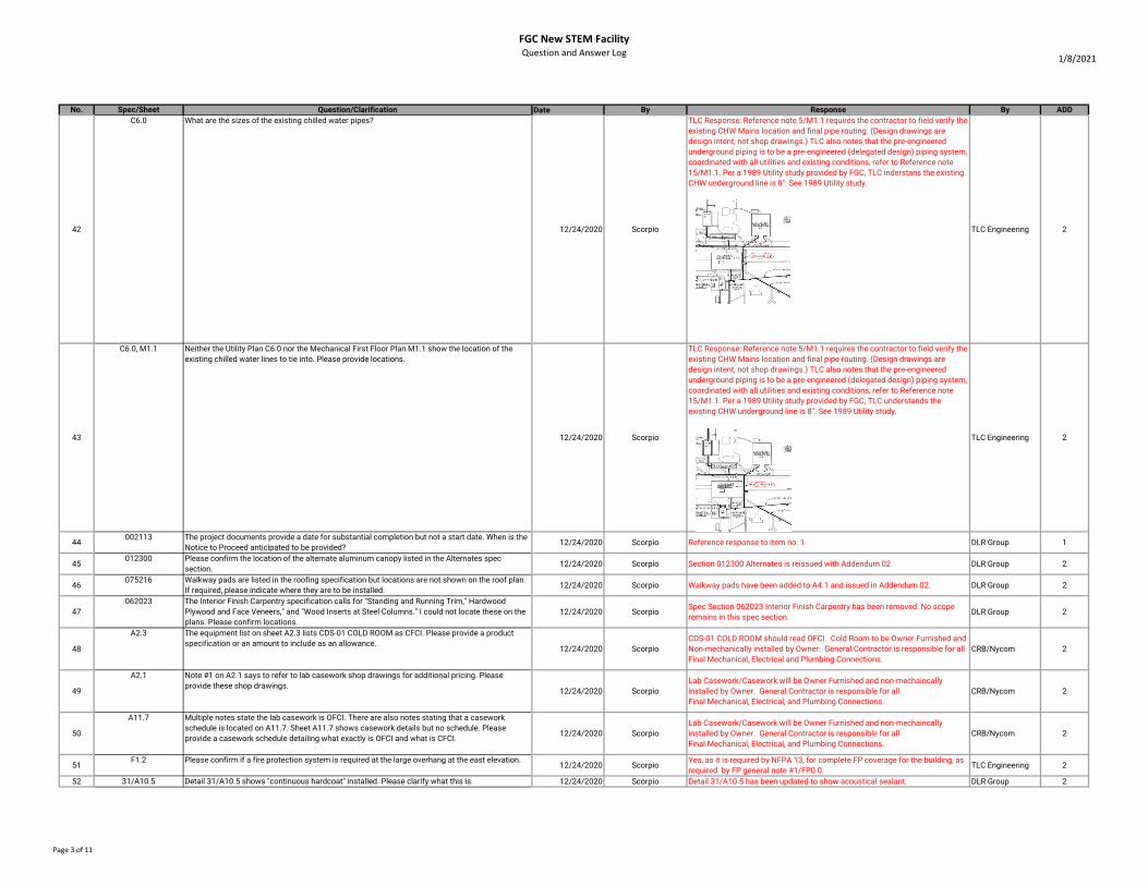
42
C6.0 What are the sizes of the existing chilled water pipes?
12/24/2020 Scorpio
TLC Response: Reference note 5/M1.1 requires the contractor to field verify the existing CHW Mains location and final pipe routing. (Design drawings are design intent, not shop drawings.) TLC also notes that the pre-engineered underground piping is to be a pre-engineered (delegated design) piping system, coordinated with all utilities and existing conditions, refer to Reference note 15/M1.1. Per a 1989 Utility study provided by FGC, TLC inderstans the existing CHW underground line is 8". See 1989 Utility study.
TLC Engineering 2
43
C6.0, M1.1 Neither the Utility Plan C6.0 nor the Mechanical First Floor Plan M1.1 show the location of the existing chilled water lines to tie into. Please provide locations.
12/24/2020 Scorpio
TLC Response: Reference note 5/M1.1 requires the contractor to field verify the existing CHW Mains location and final pipe routing. (Design drawings are design intent, not shop drawings.) TLC also notes that the pre-engineered underground piping is to be a pre-engineered (delegated design) piping system, coordinated with all utilities and existing conditions, refer to Reference note 15/M1.1. Per a 1989 Utility study provided by FGC, TLC understands the existing CHW underground line is 8". See 1989 Utility study.
TLC Engineering 2
44002113 The project documents provide a date for substantial completion but not a start date. When is the
Notice to Proceed anticipated to be provided? 12/24/2020 Scorpio Reference response to item no. 1. DLR Group 1
45012300 Please confirm the location of the alternate aluminum canopy listed in the Alternates spec
section.12/24/2020 Scorpio Section 012300 Alternates is reissued with Addendum 02 DLR Group 2
46075216 Walkway pads are listed in the roofing specification but locations are not shown on the roof plan.
If required, please indicate where they are to be installed. 12/24/2020 Scorpio Walkway pads have been added to A4.1 and issued in Addendum 02. DLR Group 2
47
062023 The Interior Finish Carpentry specification calls for "Standing and Running Trim," Hardwood Plywood and Face Veneers," and "Wood Inserts at Steel Columns." I could not locate these on the plans. Please confirm locations.
12/24/2020 ScorpioSpec Section 062023 Interior Finish Carpentry has been removed. No scope remains in this spec section.
DLR Group 2
48
A2.3 The equipment list on sheet A2.3 lists CDS-01 COLD ROOM as CFCI. Please provide a product specification or an amount to include as an allowance.
12/24/2020 ScorpioCDS-01 COLD ROOM should read OFCI. Cold Room to be Owner Furnished and Non-mechanically installed by Owner. General Contractor is responsible for all Final Mechanical, Electrical and Plumbing Connections.
CRB/Nycom 2
49
A2.1 Note #1 on A2.1 says to refer to lab casework shop drawings for additional pricing. Please provide these shop drawings.
12/24/2020 ScorpioLab Casework/Casework will be Owner Furnished and non-mechaincally installed by Owner. General Contractor is responsible for all Final Mechanical, Electrical, and Plumbing Connections.
CRB/Nycom 2
50
A11.7 Multiple notes state the lab casework is OFCI. There are also notes stating that a casework schedule is located on A11.7. Sheet A11.7 shows casework details but no schedule. Please provide a casework schedule detailing what exactly is OFCI and what is CFCI.
12/24/2020 ScorpioLab Casework/Casework will be Owner Furnished and non-mechaincally installed by Owner. General Contractor is responsible for all Final Mechanical, Electrical, and Plumbing Connections.
CRB/Nycom 2
51F1.2 Please confirm if a fire protection system is required at the large overhang at the east elevation.
12/24/2020 ScorpioYes, as it is required by NFPA 13, for complete FP coverage for the building, as required by FP general note #1/FP0.0.
TLC Engineering 2
52 31/A10.5 Detail 31/A10.5 shows "continuous hardcoat" installed. Please clarify what this is. 12/24/2020 Scorpio Detail 31/A10.5 has been updated to show acoustical sealant. DLR Group 2
Page 3 of 11

FGC New STEM Facility
Question and Answer Log1/8/2021
No. Spec/Sheet Question/Clarification Date By Response By ADD
53
31/A3.1 Detail 31/A3.3 is calling for GYB and maple veneer plywood at the ceiling. Does the maple veneer cover the entirety of the GYB or only sections of it? There are lines drawn across the detail that could be edges of the plywood.
12/24/2020 ScorpioThe ceiling in this area is GWB, painted. This detail has been updated for Addendum 02.
DLR Group 2
54 M1.1/232113Sheet M1.1, reference note #15 reads to be in conflict with 232113 Hydronic Piping, 2.3 Prefabiracted Underground Piping. What piping materials is to be used for the underground cilled water piping?
12/28/2020 Foresight
Base proposal for undergroung chilled water piping, shall be pre-engineered pre-insulated HDPE/HDPE Fusion welded CHW system per Reference note #15/M1.1. Contractor may provide a alternate deduct to utalize welded schedule 40 steel carrier pipe with HDPE outer jacket pre-engineered piping systems, in lieu of HDPE/HDPE.
TLC Engineering 2
55The Underground CHWS&R piping call for expansion loops, and thrust blocks. This usually only applies to underground heating hot water pipe systems. Can the underground chilled water piping mains be installed without the expanson loops in a straight line point to point?
12/28/2020 Foresight
TLC Response: Reference note 15/M1.1indicates that the underground CHW Piping is a pre-engineered underground CHW piping system that is to be a pre-engineered (delegated design) piping system, coordinated with all utilities and existing conditions, refer to Reference note 15/M1.1. Reference note #16/M1.1 indicates that expansion loops, thrust blocks, and pipe anchors are to be in accordance with pre-engineered piping manufactures installation guidlines and pre-engineered design drawings by them. Provide is required by the pre-engineered design by the manufacture.
TLC Engineering 2
56 064116064116 Plastic Laminate Clad Architectural Cabinets spec section was provided in Addendum 01 and this led to whether the AWI QCP certification is truly required.
12/23/2020 Foresight AWI certification will be removed from Spec Section 064116. DLR Group 2
57Please confirm that the building permit and plan reviews are by the contractors.
12/29/2020 CPPIPer Spec Section 003143, 1.1.C Permit Fees to be paid by Contractor. DOE and AHJ have already reviewed the plans and comments have been addressed in the December 4, 2020 Bid Documents.
DLR Group 2
58 004393Spec Section 004393 Bid Submittal Checklist is missing from the specifications. Please provide this spec section so it is clear what documents are required to be submitted with the bid.
12/29/2020 CPPIThe Bid Submittal Checklist has been provided in Addendum 02 along with Attachment 10.
DLR Group 2
59Are either Johns Manville or Firestone acceptable substitute products for the roofing material? If so, please specify which products should be used.
12/30/2020 Foresight We have provided three manufacturers with ample coverage of roofing sub-contractors for this project. The client has expressed a preference, which was the Basis of Design, but reviewed and approved Soprema and Tremco.
DLR Group 2
60 062023Please provide information on wood inserts for steel columns, as referenced by spec section 062023, part 1.1.A.4 and A1.3 legend #3 alludes to this possibly, nut no other info has been found.
12/30/2020 Foresight Spec Section 062023 Interior Finish Carpentry has been removed. No scope remains in this spec section. Legend #3 on A1.3 and A1.4 refers to exposed steel columns, not wood inserts.
DLR Group 2
61 A3.3Please provide a cross section/more information on the plywood called for in detail 31 on page A3.3
12/30/2020 Foresight Plywood has been removed, see updated detail 31/A3.3. DLR Group 2
62Many lab casework/casework subcontractors have declined to bid on installation only of the Kewaunee products. There is not a good way to services or warranty an item provided by owner in this case. Please provide a list of contractors approved by FGC to install these OFCI products.
12/30/2020 Foresight Lab Casework/Casework will be Owner Furnished and non-mechaincally installed by Owner. General Contractor is responsible for all Final Mechanical, Electrical, and Plumbing Connections.
CRB/Nycom 2
63 081000
Is Allegion an approved equal to the specified Assa Abloy door hardware? Attached is a formal substitution request. 12/31/2020 Scherer Construction
This substitution is Rejected. As long as there is not serious budget issues with the Hardware, FGC would prefer to keep the project as specified for now.
DLR Group/FGC 3
64 Please confirm if GAF products can be used in lieu of Siplast for the SBS Modified Bitumen Roofing System.
12/31/2020 Scherer ConstructionWe have provided three manufacturers with ample coverage of roofing sub-contractors for this project. The client has expressed a preference, which was the Basis of Design, but reviewed and approved Soprema and Tremco.
DLR Group 2
65 A11.7There are requests for alternates within the plans (A11.7, M5.1, & M7.3) These alternates are not noted in section 012300. Do you want the General Contractor to provide the alternates listed within the plans?
12/31/2020 Scherer ConstructionAlternates on A11.7 are Lab Casework/Casework furnished by the Owner. Alternates referenced on M5.1 have been added to the Schedule of Alternates in spect section 012300. Could not locate any alternates called out on M7.3.
CRB/TLC 2
66 051200
There is conflicting language regarding the AISC Certification. Note 1 under "Notes to GC & Owner" per Sheet S1.2 highly recommends a selection of an AISC Certified fabricator. However, Spec Section 051200 -2.1 Acceptable Fabricators states that AISC Certification or independent certification in accordance with AISC is required for fabrication. Please clarify if there is an AISC Certification / independent certification requirement for fabrication and/or erection.
12/31/2020 Scherer ConstructionBBM Reply: There is no conflict. The option to use a Non-AISC certified fabricator is given, although we recommend that an AISC certified fabrication be used.
BBM 2
67Please clarify that all of the laboratory casework is sole sourced by Kewaunee and is to be contractor furnished and contractor installed. The equipment list per A2.1 only specifies equipment, there is no information on who's providing casework.
12/31/2020 Scherer ConstructionLab Casework/Casework will be Owner Furnished and non-mechaincally installed by Owner. General Contractor is responsible for all Final Mechanical, Electrical, and Plumbing Connections.
CRB/Nycom 2
68Please provide material for the men's and women's restroom countertops that contain double sinks per detail 12/31/2020 Scherer Construction Refer to updated restroom elevation on A2.4 and updated detail in A11.1. DLR Group 2
69 T6.1On page T6.1, detail #2 shows a 24 strand multimode fiber between MDF158 and IDF261 on 1st and 2nd floors, but singlemode fiber is being installed to the building. Please confirm this detail should show Singlemode and we are not to install multimode fiber.
12/31/2020 Scherer ConstructionOriginal design calls for 24 MM fiber between 1st and 2nd floor. This is correct. However, we will add 6 SM fiber for good measure.
TLC Engineering 3
Page 4 of 11

FGC New STEM Facility
Question and Answer Log1/8/2021
No. Spec/Sheet Question/Clarification Date By Response By ADD
70 T6.1On page T6.1, Detail #2 doesn’t show how many strands of fiber are to be installed between Building #15 and MDF 158 or Building #7 and MDF 158. Please clarify.
12/31/2020 Scherer ConstructionRiser diagram should read MDF Bldg. 23 instead of MDF Bldg. 15. Pull (48) SM fiber from Bldg. 23 to STEM MDF 158. See Item 71 below for additional information.
TLC Engineering 3
71 T6.1On Page T6.1, Detail #1 calls for the fiber to be blown back to the manhole and fusion spliced. This fiber is meant to be blown in and out of the tube. The fiber should be blown out all the way to building #7 and reinstalled after the slab is done, doing away with the need to be spliced.
12/31/2020 Scherer Construction
The current fiber risers on the drawings were originally designed when the existing building was still standing. Since the existing building is now gone, these risers are now incorrect. New design should be (48) SM fiber fed from campus main computer room in Building 23 to new STEM MDF 158. Contractor shall match existing fiber termination types. New design will be reflected on drawings in next Addendum.
TLC Engineering 3
72 T1.0T1.0 detail from existing telecomm manhole to building calls for (6EA) airblown fiber 1 1/2" microducts. The specified product comes in a tube that has 2,4, 7 or 19 tubes inside of it. Please confirm (7EA) is acceptable.
12/31/2020 Scherer Construction Provide (7 EA) 1-1/2" microducts. TLC Engineering 3
73 092400Please confirm desired finish for cement plaster. Spec section 092400 Page 3, Section F.1a states to refer to painting specs for coating scope and product info. However, spec section 09900 contains no information for it. Please clarify.
12/31/2020 Scherer ConstructionFinish and Coatings have been updated in this spec section to reflect the Integrally Colored and Finish system within Parex DPR product.
DLR Group 2
74
Are any alternates or substitutions to Parex USA, Inc. for EIFS being considered at this time?
12/31/2020 Scherer ConstructionOther Continous Insulation Stucco system providers will be acceptable. Contractor shall verify the components of meet the intent of the details and specified performance.
DLR Group 2
75 62023
Spec Section "06-2023 Interior Finish Carpentry" calls for Painted standing and running trim and hardwood plywood and face veneers, although it is not indicated on the drawngings, please clarify.
12/31/2020 Scherer ConstructionSpec Section 062023 Interior Finish Carpentry has been removed. No scope remains in this spec section.
DLR Group 2
76 Please confirm if there are any alternative manufacturers for the modular metal wall and ceiling system.
12/31/2020 Scherer Construction
Longboard 4" V-groove, tongue and groove system. Finish to be selected from available finishes during submittals: https://www.longboardproducts.com/available-finishes. Contractor must verify all Florida Product Approval is updated and accurate.
DLR Group 2
77
Please clarify where the staging/layout area will be located.
12/31/2020 Scherer ConstructionThe parking lot directly south of the site will be closed by the college for the duration of construction and will be used for staging and access to the site.
FGC 2
78 14000 Spec Section 014000 Quality Requirements are not included, can this be provided? 1/5/2021 Foresight This section has been provided in Addendum 02. DLR Group 2
79 A4.1On page A4.1, RF-2 lists coverboard with a question mark. Please confirm that ½” coverboard will be necessary and sufficient.
1/5/2021 Foresight 1.2" coverboard is required and RF-2 has been updated in Addendum 02. DLR Group 2
80 A4.1The roofing specs call for walkway pads, which are not shown on the roofing plan. Please confirm that this is an extraneous spec.
1/5/2021 Foresight A4.1 has been updated with walkway pads and provided in Addendum 02. DLR Group 2
81 A4.1, A5.1The roofing specs call for gutters and downspouts, but none are depicted on the plans. Please confirm that this is an extraneous spec.
1/5/2021 Foresight Per Keynote 01 on A4.1, there is a downpout at the back stair canopy. Downspout is also called out in Exterior Elevations 31/A5.1 and 45/A5.1.
DLR Group 2
82 M1.1/232113 Per page M1.1 note 15 does not match spec section 232113-4. Are we to go by plans or specs? 1/5/2021 Foresight
See Prebid RFI-22 response issued prior: TLC Response: Reference note 5/M1.1 requires the contractor to filed verify the existing CHW Mains location and final pipe routing. (Design drawings are design intent, not shop drawings.) TLC also notes that the pre-engineered underground piping is to be a pre-engineered (delegated design) piping system, coordinated with all utilities and existing conditions, refer to Reference note 15/M1.1.
TLC Engineering 3
83 Commisioning Specification - Code Commisioning Agent 1/5/2021 N/A
See attached comissioning specification issued in Addendum #3. Contractor shll carry $25,000 allowance for comissioning Agent, as noted in 019113-1.2-A-1. Quantity to be comissioned was updated for clarification also in 019113-3.3-H.
TLC Engineering 3
84 004113, 012300
Specification Section 004113 – Bid Form currently only has a Base Bid listed. However, Speciation Section 012300 – Alternates has an Alternate #1 “Canopy over existing doors at the active classrooms.”
Please clarify and/or advise where pricing for Alternate #1 shall be submitted.
1/6/2021 StellarRevised Bid Alternates spec section was issued in Addendum 02. Alternate option for "Canopy over existing doors at the active classrooms" has been removed.
DLR Group 3
85 A11.7, 012300
Drawing A11.7 – Casework Schedule has a note below the “Mobile Cabinets – MC” elevation that states “Provide Add Alternate price to provide 1” resin countertops at all mobile cabinets.” Per the Specification Section 012300 – Alternate Section, this alternate is not listed on the Bid Form.
Please clarify and/or advise where pricing for this alternate shall be submitted.
1/6/2021 Stellar Alternates on A11.7 are Lab Casework furnished by the Owner. CRB/Nycom 3
86 A9.1, 083324
Per the Door Schedule on Drawing A9.1, Door #108A is a 6’0” x 7’0” 45-minute Rated Fire Shutter. Currently there is not a specification section for this Fire Shutter.
Please provide specifications for this Fire Shutter.
1/6/2021 StellarSpec Section 083324 Overhead Coiling Fire Doors have been added. In addition, details have been added to sheet A9.3. and issued in Addendum 02 on 1/5/2021.
DLR Group 3
Page 5 of 11

FGC New STEM Facility
Question and Answer Log1/8/2021
No. Spec/Sheet Question/Clarification Date By Response By ADD
87 107113
Specification Section 10711 – Exterior Sunshades, calls out for C.R. Laurence 7750 Series Aluminum Sunshades, however, these cannot be located within the project drawings.
Please advise if Exterior Sunshades are to be part of the project and if so, please advise on size and locations.
1/6/2021 Stellar Reference response to item No. 11. DLR Group 3
88 A4.2
Per Drawing A4.2, “Pre-Finished Suspended Aluminum Canopy Systems w/ Internal Drains” are shown, however, this is not a specification section included for these metal copies.
Please provide specifications section for these metal canopy systems.
1/6/2021 StellarSpec Section 133435 Fabricated Walkway Covers has been added to Addendum 03.
DLR Group/BBM 3
89 A8.3, 071700
Per Drawing A8.3, Section 22 & 23, call out for Metal Oxide Waterproofing on the soil side of the elevator pit walls. However, per Specification Section 071700, Bentonite Waterproofing is called out for below grade on concrete walls.
Please advise which waterproofing system is to be provided and/or provide specifications as required.
1/6/2021 Stellar Spec Section 071700 is correct, see updated Sections 22 & 23 on A8.3. DLR Group 3
90 A7.1, A7.2, A7.2
Per Drawings A7.1, A7.2 & A7.3, the wall sections call out for “VM” Vapor Membrane (Specification Section 072100) beneath the interior slabs and foundations. There is what appears to be gravel fill beneath the slab and membrane.
Please clarify if the gravel fill is required on this project.
1/6/2021 Stellar Yes, both vapor membrane and gravel are required. DLR Group 3
91 A9.1
Per Drawing A9.1, the Door Schedule shows Door E103 as having a Type 4 Door Frame (Sidelight Frame). However, per the Floor Plan A1.3 and the Exterior Elevation 21 on A5.1, this door is shown with a Type 3 Frame.
Please advise which is correct. Please also advise if Type 4 Door Frames are currently included within the project.
1/6/2021 StellarDoor E103 has a Type 3 Frame. There are no doors with Type 4 Frames in the scope currently. See revised door schedule.
DLR Group 3
92 A2.3
Per the equipment list on Architectural Drawing A2.3, the Cold Storage (Room 214) is noted as “CFCI”, however, in the remarks column there is a note that reads “By NYCOM, provide metro shelving for cold storage.”Please confirm if the Cold Storage Room (Walk-in Cooler) and Metro Shelving are to be CFCI or to be OFOI. If the Cold Storage Room (Walk-in Cooler) and/or Metro Shelving is to be CFCI, please provide a basis-of-design and/or specifications.
1/6/2021 Stellar
CDS-01 COLD ROOM should read OFCI. Cold Room to be Owner Furnished and Non-mechanically installed by Owner. General Contractor is responsible for all Final Mechanical, Electrical and Plumbing Connections.
Metro Wire Shelving is OFOI.
CRB/Nycom 3
93 A2.1, A2.3
Per the Equipment Lists on Drawings A2.1 & A2.3, several items are listed as “Owner Furnished and Contractor Installed.”
For pricing purposes, please provide cut sheets and/or specifications for all items to be Owner Furnished and Contractor Installed.
1/6/2021 Stellar
ICE-01; PW-03; BSC-01; BSC-02; BSC-03; PW-04; FH-07; BSC-04; BSC-05; DW-02; CDS-01; PW-01; FH-01; FH-02; FH-03; DW-01; PW-02; FH-04; FH-05; FH-06 will be Owner Furnished and non-mechaincally installed by Owner.
General Contractor is responsible for all Final Mechanical, Electrical, and Plumbing Connections.
CRB/Nycom 3
94 A2.1, A2.2. A2.3
Per Drawings A2.1, A2.2 & A2.3, General Note #1 states “Owner will procure the lab casework and equipment indicated as owner furnished. Refer to casework shop drawings for additional information or pricing quote prior to shop drawing completion, Contractor to use shop drawings for bidding and coordination. Contractor responsible for installation services.”
Please provide shop drawings as these were not included within the Bid Documents.
1/6/2021 StellarLab Casework will be Owner Furnished and non-mechaincally installed by Owner. General Contractor is responsible for all Final Mechanical, Electrical, and Plumbing Connections.
CRB 3
95A2.1, A2.2. A2.3, A11.8,
A11.9
Per Drawings A2.1, A2.2 & A2.3, General Note #2 states “See detail sheets A11.8 & A11.9 for information on laboratory casework and associated accessories.” Per sheets A11.8 & A11.9, none of the items designates who is to provide and who is to install.
Please clarify which items are to OFOI, OFCI or CFCI. If items are to be OFCI or CFCI, please provide cutsheets and/or as required.
1/6/2021 StellarLab Casework and associated accessories will be Owner Furnished and non-mechaincally installed by Owner. General Contractor is responsible for all Final Mechanical, Electrical, and Plumbing Connections.
CRB 3
96 A11.7
Per the Casework Schedule on A11.7, none of the equipment designates who is to provide and who is to install.
Please clarify which items are to OFOI, OFCI or CFCI. If items are to be OFCI or CFCI, please provide cutsheets and/or as required.
1/6/2021 StellarLab Casework Schdule on A11.7 and associated accessories will be Owner Furnished and non-mechaincally installed by Owner. General Contractor is responsible for all Final Mechanical, Electrical, and Plumbing Connections.
CRB 3
97 066116, A10.2
Per Specification Section 066116 – Solid Surfacing Fabrications calls out for Solid Surfaces to be installed at interior windowsills. However, per A10.2, Gypsum Sills are shown for interior windowsills.
Please advise which material is to be provided at interior windowsills.
1/6/2021 StellarWindowsill details on A10.2 were updated and issued in Addendum 02 to show solid surface.
DLR Group 3
Page 6 of 11

FGC New STEM Facility
Question and Answer Log1/8/2021
No. Spec/Sheet Question/Clarification Date By Response By ADD
98 A10.5, A12.0
Per Drawing A10.5 Detail #26, FRP Paneling is shown at the mop sinks. However, FRP is not currently shown on the Interior Materials List on A12.0 and there is not currently a specification included for this FRP.
Please provide specification as required.
1/6/2021 StellarProvide TL1 Ceramic Wall Tile at Mop Sinks. See updated Room Finish Schedule, Finish Plans, and A10.5.
DLR Group 3
99 C2.0
Drawing C2.0 Demolition Plan was provided for information purposes only.
Please provide post demolition survey that will show expected grades for reference for civil and site work activities.
1/6/2021 StellarNo survey was done post-demolition. Contractor has option to visit site to obtain whatever information they feel is necessary for bid, or bid project with information currently in hand.
NFPS 3
100 102800
Per Specification Section 102800 – Toilet & Bath Accessories, Mop Holders with Shelf and Rag Hooks, Utility Hooks and Shower Seats are listed under section 2.4 Miscellaneous Items. Please confirm locations and quantities for all Mop Holders, Utility Hooks and Shower seats to be CFCI.
1/6/2021 Stellar(4) utility shelves and (2) utility hooks per each Janitor’s Closet. There are no shower seats in the project. Refer to detail 26/A10.5.
DLR Group 3
101
Please also confirm/verify if the following items are to be CFCI, OFCI, or OFOI as these items are not notated on the equipment list(s):
1.Storage/Chem-Prep Room 108 Flammable Cabinet (noted as T43FL) 2.Storage/Chem-Prep Room 108 Cabinet (noted as T43CH) 3.Storage/Chem-Prep Room 108 (noted as T48A) 4.Storage Room 202 Cabinets (noted as T36C) 5.Storage/Prep Room 204 Cabinets (noted as T48C) 6.Gas Cylinder Rack Tie-Down 7.Stainless Steel Pegboard Drying Racks
1/6/2021 Stellar These items are OFOI. CRB 3
102 270000Division 27 pathways. Are j-hooks allowed or is conduit to be installed in the tray?
1/6/2021 StellarFrom conduit stubbed above wall outlets, J-hooks shall be used to support cabling until it reaches the cable tray.
TLC Engineering 3
103 Will WAPs be OFCI? 1/6/2021 StellarWAPs furnished and installed by Owner. Contractor shall coil cable above WAP locations
TLC Engineering 3
104No mention of Broadband system on the plans. In the specifications it is incredibly detailed. Is there a broadband system included in the scope for this project?
1/6/2021 StellarDisregard specification 274134. It is TLC's understanding that a broadband system or CATV service into the building is not required.
TLC Engineering 3
105 TV locations, verify that each location will receive 1 Category 6 cable? What color? 1/6/2021 Stellar See details on sheet T6.2 for TV outlet requirements. TLC Engineering 3
106 Will the design team accept a conventional fiber solution as opposed to the ABF for backbone? 1/6/2021 StellarA conventional fiber solution will not be accepted. Air blown fiber solution shall be used as specified.
TLC Engineering 3
107Fiber riser only identifies 24 strand fiber between floors of new building it does not mention the OSP fiber count. Please advise.
1/6/2021 Stellar
The current fiber risers on the drawings were originally designed when the existing building was still standing. Since the existing building is now gone, these risers are now incorrect. New design shall be (24)MM OM4 and 6 SM fiber between floors and OSP shall be (48)SM fiber fed from campus main computer room in Building 23 to new STEM MDF 158. Contractor shall match existing fiber termination types. New design will be reflected on drawings in Addendum 03.
TLC Engineering 3
108 Please verify that no other OSP cable will connect to this building, other than fiber. 1/6/2021 StellarNo other OSP cable other than fiber will be pulled. Service provider shall provide copper voice cabling into building.
TLC Engineering 3
109 275113Division 275113 , speaker locations shown on plans, one detail calls out atlas PT#s (T6.3) and another note (T6.5) says JBL , OFCI. Please clarify intent. •Is any headend equipment included in the scope?
1/6/2021 Stellar
Speaker symbols and types have been revised in Addendum 03.S1 = classroom A/V speakers S2 = paging speakers (pendant) for open ceiling areas. S3 = paging speakers (ceiling) for hallways.Specification 275113 updated with Addendum 03. Refer to section 2.7 for updated part numbers to be used.
TLC Engineering 3
110 275113Spare Parts and tools (275113-13) Speakers: complete quantity of each type. Should spare quantity match installed quantity?
1/6/2021 StellarProvide (1) spare speaker of each type specified in section 2.7. Section 3.10 updated with Addendum 03.
TLC Engineering 3
Page 7 of 11
FGC New STEM Facility
Question and Answer Log1/8/2021
No. Spec/Sheet Question/Clarification Date By Response By ADD
111 282000
Division 282000, Please provide more detail on the camera system if it is required for this project. •Do we provide any licensing or software? •Do we provide any equipment other than the camera and mounting hardware? •Several cameras mentioned in the specifications (13), which cameras are to be installed on this
project and at which locations? •Install one category 6 green cable to each camera location shown on plans?
1/6/2021 Stellar
Provide rough-in and (1) CAT-6 cable for camera locations. All wall-mount camera locations shall be provided with blank plates. Ceiling loations shall have cable coiled in ceiling above.Contractor may provide Alternate Bid Pricing for a surveillance camera system to include cameras, NVRs, camera video management software and required licenses according to specification 282000. Cameras shall have minimum resolution of 3MP. Coordinate cable colors with Owner.
TLC Engineering 3
112Please clearly identify all, OF and OFCI material for the Electrical & Electrical systems Scope of work.
1/6/2021 StellarAll material for electrical and electrical systems shall be provided by contractor.
TLC Engineering 3
113
1.T6.1 illustrates the fiber riser which includes AirBlown fiber from Building 15 to the STEM building and then from the STEM building to Building 7. Is there a site drawing available that depicts the buildings referenced?
2.T6.1 also illustrates the interception of (2) fiber cables (from bldg 15 & bldg 7). What does this scope entail? Is the existing fiber to be fusion spliced AirBlown?
3.T1.0 mentions (6) 1 1/2" AirBlown fiber Micro conduits. Is this simply (6) 1 1/2" PVC conduits? 4.What is the desired strand count for the new AirBlown fiber? 5.What is the desired tube count for the new AirBlown fiber?
1/6/2021 Stellar
1. See response 107 above. T1.0 site plan is the only plan available.2. The current fiber risers on the drawings were originally designed when the existing building was still standing. Since the existing building is now gone, these risers are now incorrect. New design shall be (24)MM OM4 and (6) SM fiber between floors and OSP shall be (48)SM fiber fed from campus main computer room in Building 23 to new STEM MDF 158. Contractor shall match existing fiber termination types. New design will be reflected on drawings in Addendum 03.3. Only armored air blown innerduct manufactured for the purpose shall be used. Sumitomo TC07MSOS-2 or engineer approved equal.4. (48) strands SM air blown fiber cable by Sumitomo or Engineer approved equal.5. Tube count shall be (7).
TLC Engineering 3
114 96723
Product Substitution Request: Per Specification Section 096723 – Resinous Flooring, Everlast Epoxy Systems is not listed as an Acceptable Manufacture for the Resinous Flooring System.
Please review the attached Product Data Sheets and advise if providing Everlast Epoxy Systems (with a local representative in the Lake City area) is an acceptable alternative.
1/6/2021 Stellar This substitution is rejected. DLR Group 3
115
There are shaded RA duct systems on both first and second floors. Is this duct lined or wrapped?
1/6/2021 Scorpio
Other than exposed RA ducts, that are to be solid double wall construction, RA ducts outside the mechanical room are exterior wrapped insulation, and RA ducts in the mechaical room are to be exterior board insulation. (Refer to 230700).
TLC Engineering 3
116
Is the Lab exhaust duct stainless steel? Is it welded? The legend shows crosshatch for stainless steel duct, but no crosshatched duct is drawn on the floor plans.
1/6/2021 Scorpio
1. Lab exhaust ductwork is generally to be continously welded 316 stainless steel, minimum 18 gauge, sized and constructed respective pressure class per Current SMACNA Duct Construction manual for stainless steel ductwork. Refer to below for additional clarification.2. Lab Exhaust ducts between LEV's and LEF on the roof are to be 316 SS welded contruction, minimum 4" pressure class. for minimum 4" pressure calss. 3. Lab exhaust ducts between LEV's and Fume Hoods shall be 316 SS welded construction, minimum 3" presure class. 4. Lab exhaust ducts between room ceiling exhaust Grill and LEV shall be 316 or G90 galvanized steel, minimum 2" presure class. 5. Lab exhaust ducts between LEV's and AutoClave Heat Capture Hood shall be 316 SS welded construction, minimum 3" presure class. 6. Contractor shall provide min 24" deep steam/heat capture hood (316 SS Construction) above the autoclave (hood shall extend minimum 6" beyond equipment on sides and 2" beyond door swing). (Contractor shall provide ultra high temp FP head in the hood, for complete FP coverage with the hood being larger than 48" wide.)
TLC Engineering 3
117
M5.1 Sheet M5.1 includes (4) ADD Alternates for the Mechanical Scope. In contrast, the alternate spec section 012300 does not include any alternates applicable to Division 23 HVAC. Please request a clarification and revised Alternate spec section.
1/6/2021 ScorpioAlternate spec section was updated in Addendum #2, and the mechaical alternates are to be indicated accordingly in the contrators bids.
TLC Engineering 3
118096723 Is PlexiFlake by Plexi-Chemie an approved product for the resinous flooring? See the attached
product substitution request.1/6/2021 Scorpio This substitution is acceptable. DLR Group 3
119
033000Spec section 03 30 00 appears to be silent on moisture mitigation. Will moisture mitigation be required for the slab? If so, what system should we plan on including in our bid?
1/6/2021 CPPI
Please reference S0.1 for direction for sensitive flooring considerations. We would consider these to be carpet glue, resilient sheet flooring at slab on grade locations.
BBM 3
120
In reviewing the drawings for the Atas wall panels, it's noted that they are fastened to the wall using perforated hat channels. I am not aware of any engineering that exists for a perforated framing member as you are removing substance from the member and therefore strength. Can we use solid hat channel members in lieu of perforated?
1/6/2021 Foresight Spec Section 074800 has been added to Addendum 03 to address the attachment system required.
DLR Group 3
Page 8 of 11

FGC New STEM Facility
Question and Answer Log1/8/2021
No. Spec/Sheet Question/Clarification Date By Response By ADD
121
Are the SS-1 Wilsonart countertops that sit on top of all of the Kewaunee casework OFCI or CFCI?
1/6/2021 Foresight
SS-1 Wilsonart Solid Surface Countertops are only found at millwork (i.e. restrooms/breakroom). This millwork is CFCI. Lab Casework/Casework will be Owner Furnished and non-mechaincally installed by Owner. General Contractor is responsible for all Final Mechanical, Electrical, and Plumbing Connections.
CRB 3
122 A11.7
Basis of design for mobile base cabinets is 1” epoxy resin countertop. Page A11.7 calls for add alternate for these tops. Please clarify if resin tops are a base bid or an add alternate item, and if they are OFCI or CFCI.
1/6/2021 Foresight Alternates on A11.7 are Lab Casework furnished by the Owner.Epoxy Resin Countertops are OFOI
CRB 3
123
Substitution Request Canopies (See Attachments): For your convenience, I am enclosing a completed form CSI 1.5C and our current brochure. We offer over 18 years of experience in designing, fabricating, and installing high quality extruded aluminum sunscreens. We certify all our designs with our in-house Professional Engineers and we install our own projects with our factory-trained crews. For PDF details of our systems, please refer to our website using the link shown below.
1/6/2021 Foresight Reference response to item No. 11. DLR Group 3
124 In regards to the ACT Tile. Can you please provide the Item # for PACIFIC and HYGIENIC PLUS. 1/6/2021 Foresight See updated Finish Schedule. DLR Group 3
125In regards to the Roller Shades. Will they be Surfaced or Pocket mounted? I did not see a detail. I am asking for the Framing. 1/6/2021 Foresight Pocketed within window opening. DLR Group 3
126 A10.3Regarding the Exterior Metal Panels, Walls and Ceiling system. The plans call for Exterior Metal Wall panels, Metal Ceilings over a Liquid Moisturer Barrier, Rigid Insulation with HCI-Girt. See Detail 24/A10.3. The plans also calls for Interior Metal Wall Panels and Ceiling. Who will be responsible for this work?
1/6/2021 Foresight The exterior and interior metal wall panel and ceiling are all the same product system. It is a means & methods item for who is responsible for install at each location.
DLR Group 3
127 A12.0 Regarding finish note W3 on A12. Will the plywood go up to 8’? 1/6/2021 Foresight Note indicates to mount 4" A.F.F., thus making theTop of Plywood Panel 8’-4” for a 4’x8’ sheet.
DLR Group 3
128 A4.1The drawings call for 6” of ISO foam insulation for RF-1. This equates to more than the prescribed R-33. Is the intent to have 6” at the roof drains or an average of 6” across the whole of the roof? For reference, starting at 6” at the roof drains and tapering up from there would put over 14” of insulation at the peak. Also, the specs disagree, calling for R-30. Please provide a cross section showing dimensions for the differing depths of insulation to metal deck.
1/6/2021 Foresight
R-30 is correct for roof insulation. Provide insulation to achieve R-30 and taper as required per roof plan layout. For roof drain cross-section, refer to 11/A4.2. The roof plan and legend have been updated to reference tapered insulation.
It should be noted that the roof structure is sloped, which has been further clarified in the roof plan. Refer to Structural for more information.
DLR Group 3
129 The called for 1” of ISO foam insulation falls below the prescribed R-6 for RF-2. Please advise the depth of insulation intended for this roof area.
1/6/2021 Foresight RF-2 Roof Type is not part of the building envelope. The insulation called out is for proper roof drainage. We call out a minimum of 1" plus 1/4" per 1' slope. This should result in an average of R-6.
DLR Group 3
130 Is York an acceptable AHU manufacture? 1/6/2021 Foresight York is an acceptable alternate manufacture for the AHU's listed in 237313-2.1-A-4. AHU's shall comply with drawings and specifications.
TLC Engineering 3
131
Are Trane/Danfoss VFDs acceptable?
1/6/2021 Foresight
Danfoss or private labeled Danfoss drives for Trane, with associated disconnects and listed as a complete assembly, that comply with project drawings and specifications, would be an acceptable alternate manufacture for VFD's in 230514- 2.1-A-2.
TLC Engineering 3
132 CP1.2, A12.0Can you confirm if the expsosed ceiling in collaboration 200 will be painted? This area is also in the fireproofing area shown on CP1.2. Will this deck metal deck have fireproofing? 1/6/2021 Foresight
PAINT EXPOSED STEEL DECK AND STRUCTURE. PT1. See updated Room Finish Schedule and Ceiling Plan Notes.
DLR Group 3
133 A12.0Will the deck need to be painted underneath the metal ceiling caldding? If so, to what extent?
1/6/2021 Foresight Entire exposed deck to be painted, including areas behind finished dropped ceiling.
DLR Group 3
134 A10.3
Please confirm whether the top of the parapets will need a layer of plywood on either the top or the bottom of the wood blocking/rigid insulation underneath the coping cap as shown in the details below. 1/6/2021 Foresight
Design intent is for wood blocking members to go across, bridging the blocking on each side of the parapet so that it forms a ladder across the top of the parapet to fasten coping as required. Refer to typical parapet detail added to sheet A10.5. The suggested detail using plywood is also acceptable.
DLR Group 3
135 ADD02
Per the addendum that just came out, I have a questions regarding items #11 & 12 on the attached bid submittal checklist.
For item 11, are you wanting a letter from bonding stating we can bond this project? For item 12, you need a COI from our insurance company?
The wording “Verified” in front of those items has me confused. Sounds like we may have verified this info already to get qualified to bid.
1/6/2021 Foresight
We do not need any verification from the contractors as we already required proof of insurance and a bonding letter during the prequalification process.
We are including additional clarifications to the Bid Form and Bid Submittal Checklist as part of Addendum 03.
FGC/DLR Group 3
Page 9 of 11

FGC New STEM Facility
Question and Answer Log1/8/2021
No. Spec/Sheet Question/Clarification Date By Response By ADD
136 226713The last section of the plumbing specs “226713 PROCESSED WATER PIPING FOR LABORATORY FACILITIES” does not appear to be on the plumbing drawings anywhere. Could you please clarify the intent of this spec section?
1/6/2021 CPPIIt is on the plumbing drawings. Refer to Reference notes and associated locations on P5.2 and P5.3, as it is for local Pure water units at the reference noted various locations.
TLC Engineering 3
137 M0.0HVAC note 29/M0.0 states that SA & RA duct shown on the plans with solid and dashed lines shall be Acoustical double wall back to AHU connections. It also refers to a legend which shows neither. What is the extent of Double Wall Duct that the engineer requires?
01/072021 Gray
Exposed ductwork that is exposed/visable to the public, shall be double wall construction, per HVAC general note #2/M1.1/M1.2. Refer to architectural RCP plans that identify open ceiling areas where ducts could be seen/viwed. (i.e. Rm 120, Lobby 100, Collaboration 200)
TLC Engineering 3
138There are shaded RA duct systems on both first and second floors. Is this duct lined? Or wrapped?
01/072021 Gray
Other than exposed RA ducts, that are to be solid double wall construction, RA ducts outside the mechanical room are exterior wrapped insulation, and RA ducts in the mechaical room are to be exterior board insulation. (Refer to 230700).
TLC Engineering 3
139Is the Lab exhaust duct stainless steel and is it welded? The legend shows crosshatch for stainless steel duct, but no crosshatched duct is drawn on the floor plans.
01/072021 Gray
1. Lab exhaust ductwork is generally to be continously welded 316 stainless steel, minimum 18 gauge, sized and constructed respective pressure class per Current SMACNA Duct Construction manual for stainless steel ductwork. Refer to below for additional clarification.2. Lab Exhaust ducts between LEV's and LEF on the roof are to be 316 SS welded contruction, minimum 4" pressure class. for minimum 4" pressure calss. 3. Lab exhaust ducts between LEV's and Fume Hoods shall be 316 SS welded construction, minimum 3" presure class. 4. Lab exhaust ducts between room ceiling exhaust Grill and LEV shall be 316 or G90 galvanized steel, minimum 2" presure class. 5. Lab exhaust ducts between LEV's and AutoClave Heat Capture Hood shall be 316 SS welded construction, minimum 3" presure class. 6. Contractor shall provide min 24" deep steam/heat capture hood (316 SS Construction) above the autoclave (hood shall extend minimum 6" beyond equipment on sides and 2" beyond door swing). (Contractor shall provide ultra high temp FP head in the hood, for complete FP coverage with the hood being larger than 48" wide.)
TLC Engineering 3
140 1989 Utility Study please provide the “1989 Utility Study” referenced by TLC Engineering in RFI responses 42 and 43. 01/072021 Gray
1989 utility report has been provided in Addendum #3 as requested. Contractor is advised that this report is old, as it is from 1989. The report is only 7 pages. Contractor shall refer to site survey and civil drawings for current known site information.
TLC Engineering 3
141 Is York an acceptable AHU manufacture? 01/072021 GrayYork is an acceptable alternate manufacture for the AHU's listed in 237313-2.1-A-4. AHU's shall comply with drawings and specifications.
TLC Engineering 3
142 Are Trane/Danfoss VFDs acceptable? 01/072021 Gray
Danfoss or private labeled Danfoss drives for Trane, with associated disconnects and listed as a complete assembly, that comply with project drawings and specifications, would be an acceptable alternate manufacture for VFD's in 230514- 2.1-A-2.
TLC Engineering 3
143 Please confirm if York is an acceptable AHU manufacturer and if Trane/Danfoss VFDs are acceptable.
01/072021 StellarYork is an acceptable alternate manufacture for the AHU's listed in 237313-2.1-A-4. AHU's shall comply with drawings and specifications.
TLC Engineering 3
144 A8.2Section 44/A8.2 shows the handrail on the exterior staircase stopping before the landing/on the stair stringer but section 55/A8.2 shows it ending on the landing. Please clarify correct end location of the handrail.
01/072021 StellarBoth details are correct. Detail 55 is showing a detail of the stringer edge and the "railing" called out is the guardrail.
DLR Group 3
145 A8 Series Please confirm whether there will be any support posts for the top rail or if it will be supported by the aluminum pickets, in the exterior stairs' handrail.
01/072021 StellarDetails call out design intent for top rail support "3/4" X 3/4" ALUMINUM GUARDRAIL & PICKETS." This is a delegated design item, reference Spec Section 055202, and should be submitted during shop drawing review.
DLR Group 3
146 Technology
For a typical Classroom & Lab: 1. Is DMPS3-4K-100-C already configured with correct settings?2. Are all items in MAP rolling rack already installed, with correct wiring?3. Is the programming already done? Or AVSI need to redo the programming? 4. If the rack is not installed yet, what is the purpose of Crestron DA4-4K-C? Can we use the DM output of DMPS3-4K-100-C. Less components on the signal chain lead to less possible failure points, less heat generated.
1/7/2021 Foresight
1-3. All A/V hardware indicated on the drawings as OFCI shall be assembled, installed, mounted and programmed by Contractor as required. Contractor shall assume that nothing will arrive pre-programmed.4. Agreed. Omit the DM-DA4-4K-C.
NOTE: Although not currently shown on the drawings, the Multi-Purpose Room (120) shall have same A/V equipment & rack setup as the other classrooms. The only difference is the long throw projector vs. short throw projector. Drawings will be updated in Addendum 03.
TLC Engineering 3
Page 10 of 11

FGC New STEM Facility
Question and Answer Log1/8/2021
No. Spec/Sheet Question/Clarification Date By Response By ADD
147 Technology
For AV Riser- Conference Room:1. Is there any control needed in this room? What is the control interface. 2. There is a RS232 connection between HD-EXT-USB-2000-C RX and display. But did not see RS232 connection on HD-EXT-USB-2000-C Tx Side. The RS232 on HD-EXT-USB-2000-C is pass through only.
1/7/2021 Foresight RS232 intended to control TV from Mercury touch screen. RS232 from touch screen, thru HDMI TX and RX and on to TV. Rsier updated in Addendum 03
TLC Engineering 3
148 What is the panel type – square lay in, square tegular narrow or square tegular? 1/7/2021 Foresight Per Add #2, Ceiling Tiles are Tegular (not narrow) APC1, and Square Edge APC2. DLR Group 3
149The finish schedule lists the finish as ‘white’ – what is the intended surface finish – smooth, fine, medium, fissured, etc? 1/7/2021 Foresight Fine Texture. DLR Group 3
150 Can you confrim if the double roller shades need side channels? 1/7/2021 Foresight Per Blackout shades spec 122413, provide Side channels on black out shades only.
DLR Group 3
151Will the lab hoods be certified by Owner, or will Contractor need to certify the lab hoods?
1/7/2021 Foresight TLC Response: Certification will be by the contractor, via independent company. Notes have been indicated on M1.1 for clarification, refer to addendum #3 Drawing M1.1.
TLC Engineering 3
152 33300 Concrete Spec 033000-19: 3.8 D refers to gym, Cafeteria and Stage Floor. Confirm FF50/FL30 does not apply anywhere and which FF/FL they want for slab-on-grade and slab-on-deck.
1/7/2021 Foresight That is correct. Use values given on 3.8.C. Only FF values need to be met for elevated slab-on-deck.
BBM 3
153 S1.2 Sheet S1.2: If an opening does not have TB or a CB called out on the floor plan and if the opening is less than 16’ can we assume the opening will be crossed by a PB1, PB2 or PB3?
1/7/2021 Foresight That is correct. BBM 3
Page 11 of 11

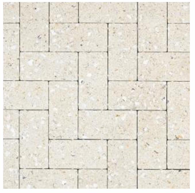
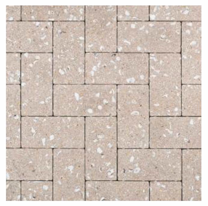
12/28/2020 Oceanside Paver System | Shell Stones Pavers
www.belgard.com/products/pavers/oceanside 1/7
Products | Collections | Pavers | Oceanside
SPECS TECHNICAL INFO
Previous
NextWALKWAYS PATIOS DRIVEWAYS POOLS
OCEANSIDELEGACY
APPLICATIONS:
PRICING:
$$
Oceanside pavers combine coquina and oyster shells with a truly durable product for a level
of natural beauty few pavers can match.
*All colors and/or products may not be available in all areas. Please inquire for availability and special order options.
COLORS
12/28/2020 Oceanside Paver System | Shell Stones Pavers
www.belgard.com/products/pavers/oceanside 2/7
Cream

12/28/2020 Oceanside Paver System | Shell Stones Pavers
www.belgard.com/products/pavers/oceanside 3/7
Gray
12/28/2020 Oceanside Paver System | Shell Stones Pavers
www.belgard.com/products/pavers/oceanside 4/7
Malt

12/28/2020 Oceanside Paver System | Shell Stones Pavers
www.belgard.com/products/pavers/oceanside 5/7
FLORIDA GATEWAY COLLEGE 36-17116-00 NEW STEM FACILITY 8 JANUARY 2021 LAKE CITY, FLORIDA ADDENDUM 03
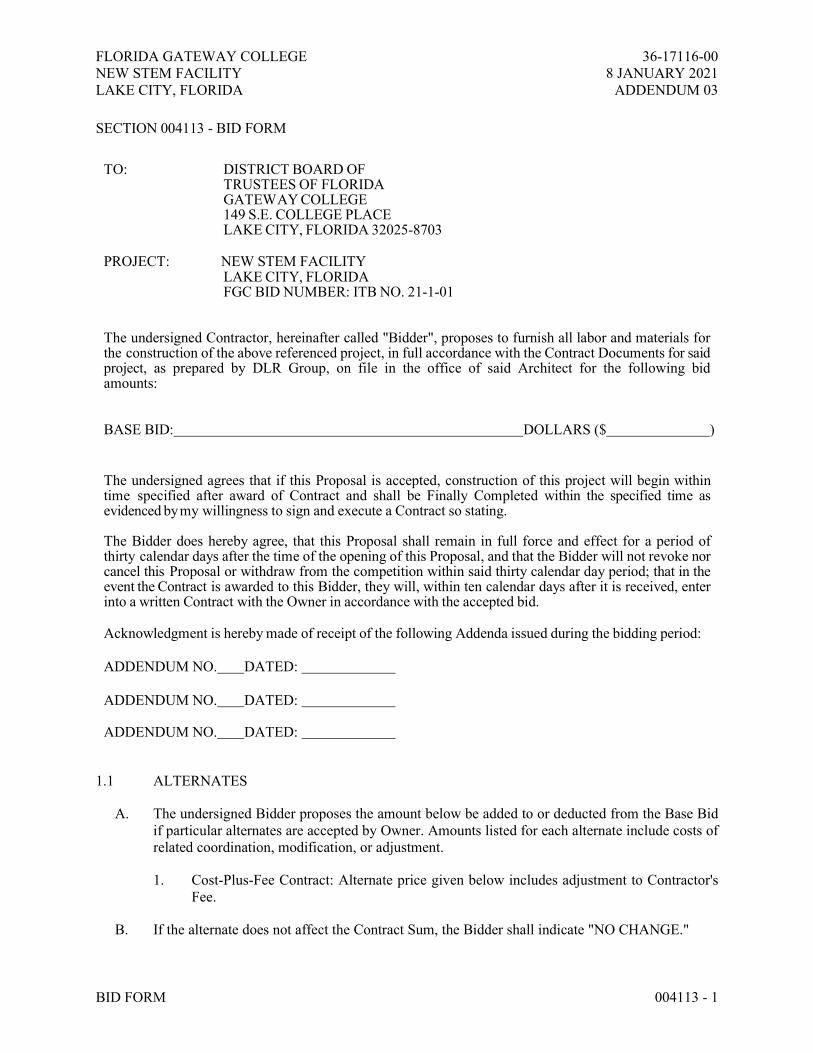
BID FORM 004113 - 1
SECTION 004113 - BID FORM
TO: DISTRICT BOARD OF
TRUSTEES OF FLORIDA GATEWAY COLLEGE 149 S.E. COLLEGE PLACE LAKE CITY, FLORIDA 32025-8703
PROJECT: NEW STEM FACILITY
LAKE CITY, FLORIDA FGC BID NUMBER: ITB NO. 21-1-01
The undersigned Contractor, hereinafter called "Bidder", proposes to furnish all labor and materials for the construction of the above referenced project, in full accordance with the Contract Documents for said project, as prepared by DLR Group, on file in the office of said Architect for the following bid amounts:
BASE BID: DOLLARS ($ )
The undersigned agrees that if this Proposal is accepted, construction of this project will begin within time specified after award of Contract and shall be Finally Completed within the specified time as evidenced by my willingness to sign and execute a Contract so stating.
The Bidder does hereby agree, that this Proposal shall remain in full force and effect for a period of thirty calendar days after the time of the opening of this Proposal, and that the Bidder will not revoke nor cancel this Proposal or withdraw from the competition within said thirty calendar day period; that in the event the Contract is awarded to this Bidder, they will, within ten calendar days after it is received, enter into a written Contract with the Owner in accordance with the accepted bid.
Acknowledgment is hereby made of receipt of the following Addenda issued during the bidding period:
ADDENDUM NO. DATED:
ADDENDUM NO. DATED:
ADDENDUM NO. DATED:
1.1 ALTERNATES
A. The undersigned Bidder proposes the amount below be added to or deducted from the Base Bid if particular alternates are accepted by Owner. Amounts listed for each alternate include costs of related coordination, modification, or adjustment.
1. Cost-Plus-Fee Contract: Alternate price given below includes adjustment to Contractor's Fee.
B. If the alternate does not affect the Contract Sum, the Bidder shall indicate "NO CHANGE."

FLORIDA GATEWAY COLLEGE 36-17116-00 NEW STEM FACILITY 8 JANUARY 2021 LAKE CITY, FLORIDA ADDENDUM 03
BID FORM 004113 - 2
C. If the alternate does not affect the Work of this Contract, the Bidder shall indicate "NOT APPLICABLE."
D. The Bidder shall be responsible for determining from the Contract Documents the affects of each alternate on the Contract Time and the Contract Sum.
E. Owner reserves the right to accept or reject any alternate, in any order, and to award or amend the Contract accordingly within [60] days of the Notice of Award unless otherwise indicated in the Contract Documents.
F. Acceptance or non-acceptance of any alternates by the Owner shall have no affect on the Contract Time unless the "Schedule of Alternates" Article below provides a formatted space for the adjustment of the Contract Time.
1.2 SCHEDULE OF ALTERNATES
A. Alternate No. 1: Variable Discharge Nozzles:
1. ADD____ DEDUCT____ NO CHANGE____ NOT APPLICABLE____.
2. ________________________________________________ Dollars ($______________).
B. Alternate No. 2: Boiler #2:
1. ADD____ DEDUCT____ NO CHANGE____ NOT APPLICABLE____.
2. ________________________________________________ Dollars ($______________).
C. Alternate No. 3: HHWP-2:
1. ADD____ DEDUCT____ NO CHANGE____ NOT APPLICABLE____.
2. ________________________________________________ Dollars ($______________).
D. Alternate No. 4: CHWP-2:
1. ADD____ DEDUCT____ NO CHANGE____ NOT APPLICABLE____.
2. ________________________________________________ Dollars ($______________).
1.3 ALLOWANCES
A. The undersigned Bidder certifies that Base Bid submission to which this Bid Supplement is attached includes those allowances described in the Contract Documents and scheduled in Section 012100 "Allowances."
B. Schedule of Allowances:

FLORIDA GATEWAY COLLEGE 36-17116-00 NEW STEM FACILITY 8 JANUARY 2021 LAKE CITY, FLORIDA ADDENDUM 03
BID FORM 004113 - 3
1. Allowance No. 1: Contingency Allowance: Include a contingency allowance of $100,000.00 for use according to Owner's written instructions.
2. Allowance No. 2: Testing and Inspection Allowance: Include the sum of $1,000.00 for testing concrete to be provided by Owner, as specified in Section 033000 "Cast-in-Place Concrete."
3. Allowance No. 3: Commissioning Agent Allowance: Include an allowance of $25,000 for a Commissioning Agent to be determined later as outlined in 013113 General Commissioning.
In witness whereof, the Bidder has hereunto set his signature and affixed his
seal this day of , A.D. 2021.
(FIRM NAME) (SEAL)
BY: (Authorized Signature) (Typed Name and Title)
Certificate Number and Type as issued to
by the (Name of Holder Representing Firm)
State of Florida Construction Industry Licensing Board.
END OF SECTION 004113

FLORIDA GATEWAY COLLEGE 36-17116-00 NEW STEM FACILITY 8 JANUARY 2021 LAKE CITY, FLORIDA ADDENDUM 03
BID FORM 004113 - 4
PROCUREMENT FORM SUPPLEMENTS
This list is attached to and is an integral part of the Bid Proposal submitted by: Firm Name: _______________________________________________ Date: ______________________ Address: _____________________________________________________________________________ For the construction of: New STEM Facility Florida Gateway College Lake City, Florida ITB 21-1-01 The undersigned, hereinafter called Contractor lists below the name of sub-contractors who will perform phases of the work indicated. Once approved by the Architect or Owner, sub-contractors listed CANNOT BE CHANGED without the express written approval of the Architect or the Owner. Sub-contractors not meeting the requirements listed below will be cause for rejection of the subcontractor. The undersigned declares that he/she has fully investigated each sub-contractor listed and has in his/her files evidence that such sub-contractor is currently and appropriately licensed in the State of Florida and engaged successfully in his/her line of work for a minimum of one (1) consecutive year prior to this Bid Date or longer if required by the Specifications for the specific section or trade, that he/she maintains a fully equipped organization capable technically and financially of performing the pertinent work and that he/she has made similar installations in a satisfactory manner. If Contractor lists himself/herself as a sub-contractor, he/she must meet all the above requirements, including licenses and/or certifications for each trade for which he/she is listed. PRIOR TO BEGINNING WORK, CONTRACTOR WILL BE REQUIRED TO SUBMIT COPIES OF ALL SUB-CONTRACTORS’, SUPPLIERS’ AND/OR VENDORS’ FLORIDA DEPARTMENT OF BUSINESS AND PROFESSIONAL REGULATIONS LICENSES, STATE REGISTRATIONS AND /OR LOCAL LICENSES AND EVIDENCE OF COMPLIANCE WITH THE ABOVE REQUIREMENTS. (License number must be inserted below) DIVISION OF WORK NAME OF SUB-CONTRACTORS LICENSE NUMBER
1. __________________________ ____________________________ ________________
2. __________________________ ____________________________ ________________ 3. __________________________ ____________________________ ________________ 4. __________________________ ____________________________ ________________ 5. __________________________ ____________________________ ________________ 6. __________________________ ____________________________ ________________

FLORIDA GATEWAY COLLEGE 36-17116-00 NEW STEM FACILITY 8 JANUARY 2021 LAKE CITY, FLORIDA ADDENDUM 03
BID FORM 004113 - 5
7. __________________________ ____________________________ ________________ 8. __________________________ ____________________________ ________________ 9. __________________________ ____________________________ ________________ 10. __________________________ ____________________________ ________________ IN WITNESS WHEREOF, the Contractor has hereunto set his/her signature and affixed his/her seal this ______day of_________________20____. BY ____________________________________________ (type name of authorized principal)
_____________________________________ ___________________________________________ (signature of principal in firm) (type firm name and title) (seal)
________________________________________ (type Contractor’s license number)
STATE OF FLORIDA COUNTY OF ________________________
The foregoing instrument was acknowledged before me, by means of � physical presence or � online
notarization this _____ day of _________________ 2020, by ____________________________
who � is personally known to me or � has produced a Florida driver’s license as identification.
___________________________________________
Notary Public, State of Florida
(NOTARIAL
SEAL) My Commission Expires:
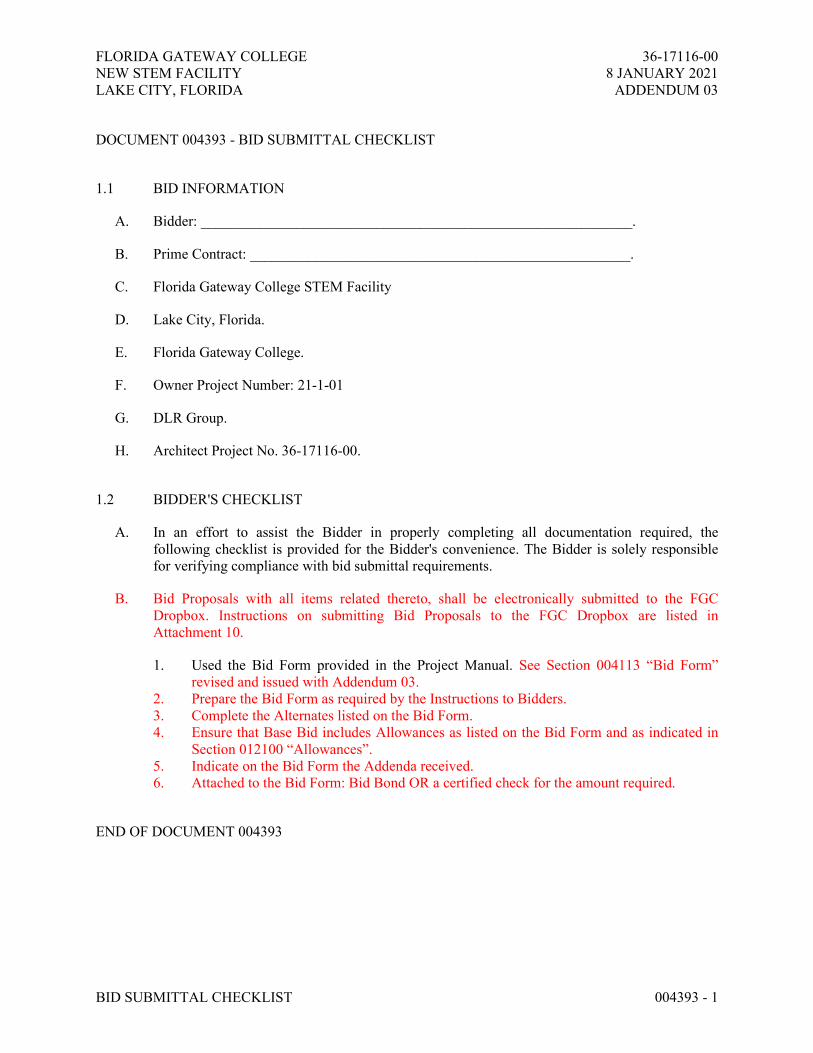
FLORIDA GATEWAY COLLEGE 36-17116-00
NEW STEM FACILITY 8 JANUARY 2021
LAKE CITY, FLORIDA ADDENDUM 03
BID SUBMITTAL CHECKLIST 004393 - 1
DOCUMENT 004393 - BID SUBMITTAL CHECKLIST
1.1 BID INFORMATION
A. Bidder: ___________________________________________________________.
B. Prime Contract: ____________________________________________________.
C. Florida Gateway College STEM Facility
D. Lake City, Florida.
E. Florida Gateway College.
F. Owner Project Number: 21-1-01
G. DLR Group.
H. Architect Project No. 36-17116-00.
1.2 BIDDER'S CHECKLIST
A. In an effort to assist the Bidder in properly completing all documentation required, the
following checklist is provided for the Bidder's convenience. The Bidder is solely responsible
for verifying compliance with bid submittal requirements.
B. Bid Proposals with all items related thereto, shall be electronically submitted to the FGC
Dropbox. Instructions on submitting Bid Proposals to the FGC Dropbox are listed in
Attachment 10.
1. Used the Bid Form provided in the Project Manual. See Section 004113 “Bid Form”
revised and issued with Addendum 03.
2. Prepare the Bid Form as required by the Instructions to Bidders.
3. Complete the Alternates listed on the Bid Form.
4. Ensure that Base Bid includes Allowances as listed on the Bid Form and as indicated in
Section 012100 “Allowances”.
5. Indicate on the Bid Form the Addenda received.
6. Attached to the Bid Form: Bid Bond OR a certified check for the amount required.
END OF DOCUMENT 004393

FLORIDA GATEWAY COLLEGE NEW STEM FACILITY 36-17116-00 FLORIDA GATEWAY COLLEGE 8 JANUARY 2021 LAKE CITY, FLORIDA ADDENDUM 03
ALLOWANCES 012100 - 1 Copyright © 2020 by the American Institute of Architects. Warning: This AIA MasterSpec based document is protected by U.S. Copyright Law and International Treaties. A valid, current MasterSpec license is required for editing or use of this document.
SECTION 012100 - ALLOWANCES
PART 1 - GENERAL
1.1 RELATED DOCUMENTS
A. Drawings and general provisions of the Contract, including General and Supplementary Conditions and other Division 01 Specification Sections, apply to this Section.
1.2 SUMMARY
A. Section includes administrative and procedural requirements governing allowances.
B. Types of allowances include the following:
1. Lump-sum allowances. 2. Contingency allowances. 3. Testing and inspecting allowances.
C. Related Requirements:
1. Section 012200 "Unit Prices" for procedures for using unit prices, including adjustment of quantity allowances when applicable.
2. Section 012600 "Contract Modification Procedures" for procedures for submitting and handling Change Orders.
3. Section 014000 "Quality Requirements" for procedures governing the use of allowances for field testing by an independent testing agency.
1.3 DEFINITIONS
A. Allowance: A quantity of work or dollar amount included in the Contract, established in lieu of additional requirements, used to defer selection of actual materials and equipment to a later date when direction will be provided to Contractor. If necessary, additional requirements will be issued by Change Order.
1.4 SELECTION AND PURCHASE
A. At the earliest practical date after award of the Contract, advise Architect of the date when final selection, or purchase and delivery, of each product or system described by an allowance must be completed by the Owner to avoid delaying the Work.
B. At Architect's request, obtain proposals for each allowance for use in making final selections. Include recommendations that are relevant to performing the Work.

FLORIDA GATEWAY COLLEGE NEW STEM FACILITY 36-17116-00 FLORIDA GATEWAY COLLEGE 8 JANUARY 2021 LAKE CITY, FLORIDA ADDENDUM 03
ALLOWANCES 012100 - 2 Copyright © 2020 by the American Institute of Architects. Warning: This AIA MasterSpec based document is protected by U.S. Copyright Law and International Treaties. A valid, current MasterSpec license is required for editing or use of this document.
C. Purchase products and systems selected by Architect from the designated supplier.
1.5 ACTION SUBMITTALS
A. Submit proposals for purchase of products or systems included in allowances in the form specified for Change Orders.
1.6 INFORMATIONAL SUBMITTALS
A. Submit invoices or delivery slips to show actual quantities of materials delivered to the site for use in fulfillment of each allowance.
B. Submit time sheets and other documentation to show labor time and cost for installation of allowance items that include installation as part of the allowance.
C. Coordinate and process submittals for allowance items in same manner as for other portions of the Work.
1.7 LUMP-SUM ALLOWANCES
A. Allowance shall include cost to Contractor of specific products and materials ordered by Owner or selected by Architect under allowance and shall include taxes, freight, and delivery to Project site.
B. Unless otherwise indicated, Contractor's costs for receiving and handling at Project site, labor, installation, overhead and profit, and similar costs related to products and materials ordered by Owner or selected by Architect under allowance shall be included as part of the Contract Sum and not part of the allowance.
C. Unused Materials: Return unused materials purchased under an allowance to manufacturer or supplier for credit to Owner, after installation has been completed and accepted.
1. If requested by Architect, retain and prepare unused material for storage by Owner. Deliver unused material to Owner's storage space as directed.
1.8 CONTINGENCY ALLOWANCES
A. Use the contingency allowance only as directed by Architect for Owner's purposes and only by Change Orders that indicate amounts to be charged to the allowance.
B. Contractor's overhead, profit, and related costs for products and equipment ordered by Owner under the contingency allowance are included in the allowance and are not part of the Contract Sum. These costs include delivery, installation, taxes, insurance, equipment rental, and similar costs.
FLORIDA GATEWAY COLLEGE NEW STEM FACILITY 36-17116-00 FLORIDA GATEWAY COLLEGE 8 JANUARY 2021 LAKE CITY, FLORIDA ADDENDUM 03
ALLOWANCES 012100 - 3 Copyright © 2020 by the American Institute of Architects. Warning: This AIA MasterSpec based document is protected by U.S. Copyright Law and International Treaties. A valid, current MasterSpec license is required for editing or use of this document.
C. Change Orders authorizing use of funds from the contingency allowance will include Contractor's related costs and reasonable overhead and profit.
D. At Project closeout, credit unused amounts remaining in the contingency allowance to Owner by Change Order.
1.9 TESTING AND INSPECTING ALLOWANCES
A. Testing and inspecting allowances include the cost of engaging testing agencies, actual tests and inspections, and reporting results.
B. The allowance does not include incidental labor required to assist the testing agency or costs for retesting if previous tests and inspections result in failure. The cost for incidental labor to assist the testing agency shall be included in the Contract Sum.
C. Costs of testing and inspection services not specifically required by the Contract Documents are Contractor responsibilities and are not included in the allowance.
D. At Project closeout, credit unused amounts remaining in the testing and inspecting allowance to Owner by Change Order.
1.10 ADJUSTMENT OF ALLOWANCES
A. Allowance Adjustment: To adjust allowance amounts, prepare a Change Order proposal based on the difference between purchase amount and the allowance, multiplied by final measurement of work-in-place where applicable. If applicable, include reasonable allowances for cutting losses, tolerances, mixing wastes, normal product imperfections, required maintenance materials, and similar margins.
1. Include installation costs in purchase amount only where indicated as part of the allowance.
2. If requested, prepare explanation and documentation to substantiate distribution of overhead costs and other markups.
3. Submit substantiation of a change in scope of Work, if any, claimed in Change Orders related to unit-cost allowances.
4. Owner reserves the right to establish the quantity of work-in-place by independent quantity survey, measure, or count.
B. Submit claims for increased costs due to a change in the scope or nature of the allowance described in the Contract Documents, whether for the purchase order amount or Contractor's handling, labor, installation, overhead, and profit.
1. Do not include Contractor's or subcontractor's indirect expense in the Change Order cost amount unless it is clearly shown that the nature or extent of Work has changed from what could have been foreseen from information in the Contract Documents.
2. No change to Contractor's indirect expense is permitted for selection of higher- or lower-priced materials or systems of the same scope and nature as originally indicated.
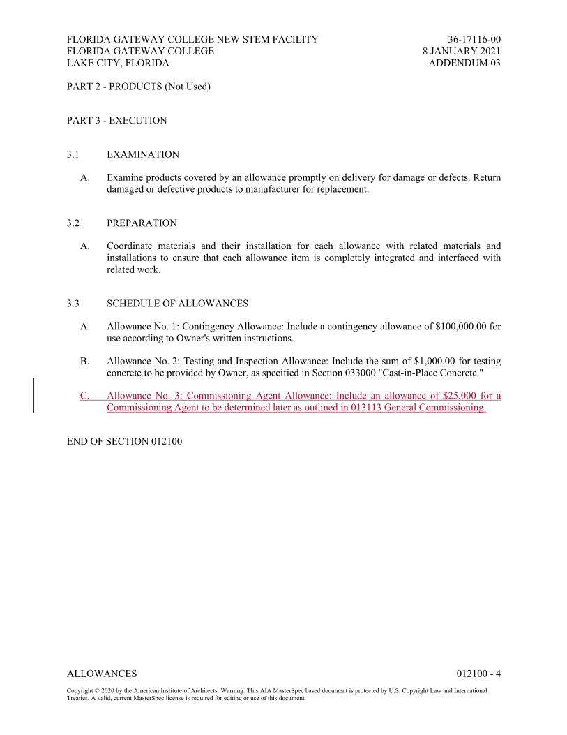
FLORIDA GATEWAY COLLEGE NEW STEM FACILITY 36-17116-00 FLORIDA GATEWAY COLLEGE 8 JANUARY 2021 LAKE CITY, FLORIDA ADDENDUM 03
ALLOWANCES 012100 - 4 Copyright © 2020 by the American Institute of Architects. Warning: This AIA MasterSpec based document is protected by U.S. Copyright Law and International Treaties. A valid, current MasterSpec license is required for editing or use of this document.
PART 2 - PRODUCTS (Not Used)
PART 3 - EXECUTION
3.1 EXAMINATION
A. Examine products covered by an allowance promptly on delivery for damage or defects. Return damaged or defective products to manufacturer for replacement.
3.2 PREPARATION
A. Coordinate materials and their installation for each allowance with related materials and installations to ensure that each allowance item is completely integrated and interfaced with related work.
3.3 SCHEDULE OF ALLOWANCES
A. Allowance No. 1: Contingency Allowance: Include a contingency allowance of $100,000.00 for use according to Owner's written instructions.
B. Allowance No. 2: Testing and Inspection Allowance: Include the sum of $1,000.00 for testing concrete to be provided by Owner, as specified in Section 033000 "Cast-in-Place Concrete."
C. Allowance No. 3: Commissioning Agent Allowance: Include an allowance of $25,000 for a Commissioning Agent to be determined later as outlined in 013113 General Commissioning.
END OF SECTION 012100

FLORIDA GATEWAY COLLEGE 36-17116-00
NEW STEM FACILITY 8 JANUARY 2021
LAKE CITY, FLORIDA ADDENDUM 03
GENERAL COMMISSIONING REQUIREMENTS 019113 - 1
SECTION 019113 GENERAL COMMISSIONING REQUIREMENTS
PART 1 - GENERAL
1.1 SUMMARY
A. Drawings and general provisions of the Contract, including General and Supplementary
Conditions and other Division 01 Specification Sections, apply to this Section.
1. Division 22 – Plumbing
2. Division 23 – Mechanical
3. Division 26 – Electrical
4. Owner’s Project Requirements (OPR) and Basis of Design (BOD) documentation are
included by reference for information only.
B. It is of primary concern that all systems and assemblies in the project perform in accordance
with the design intent and the Owner's operational needs. The process of assuring that such
performance is achieved is referred to as "commissioning."
C. The Commissioning Team will include representatives of the Owner, Design A/E, General
Contractor and Installing Subcontractors, Test and Balance Subcontractor, BAS Subcontractor
and Commissioning Authority (CxA).
D. Commissioning is a comprehensive and systematic process of verifying that the building
systems perform interactively in accordance with the BOD, according to the construction
documents and the OPR.
1. The commissioning process shall encompass and coordinate the equipment and system
documentation, equipment startup, field testing, control system calibration, testing and
balancing, functional performance testing and training. Commissioning requires
cooperation and direct involvement by all parties throughout the construction process.
2. In addition to fulfilling scheduling and planning requirements, the Contractor is further
responsible for documenting the equipment and system installation and operational
verification for all systems and assemblies.
E. Commissioning Process Overview: The following narrative provides a brief overview of the
typical commissioning tasks during construction and the general order in which they occur.
1. Various sections of the project specifications require equipment start-up, testing, and
adjusting services. Requirements for start-up, testing, and adjusting services specified in
the General Requirements, Division 22, Division 23, and Division 26 series sections of
the specifications are intended to be provided in coordination with the commissioning
services and are not intended to duplicate services. The Contractor shall coordinate the
work required by individual specification sections with the commissioning services
requirements specified herein.
2. The commissioning process does not take away from or reduce the responsibility of the
Contractor to provide a finished and fully functioning and performing product.

FLORIDA GATEWAY COLLEGE 36-17116-00
NEW STEM FACILITY 8 JANUARY 2021
LAKE CITY, FLORIDA ADDENDUM 03
GENERAL COMMISSIONING REQUIREMENTS 019113 - 2
3. The Commissioning Authority (CxA), is not responsible for construction means and
methods, job safety, or management function related to commissioning on the jobsite.
4. Commissioning begins with the selection of the Commissioning authority for the project
and the development of the OPR document.
5. Commissioning Plan: The commissioning plan provides guidance in the execution of the
commissioning process. The Commissioning Authority will prepare and update the plan.
The Specifications will facilitate the execution of the Commissioning Plan
6. Design Phase Commissioning includes a design phase kick-off meeting to discuss
commissioning requirements with the designers. The design phase will also include the
production of the BOD documents by the design team as well as design review meetings
and coordination between members of the Commissioning Team.
7. Commissioning during construction begins with a planning meeting followed by a kick-
off meeting conducted by the Commissioning Authority where the commissioning
process is reviewed with the commissioning team members.
8. Equipment and assembly documentation is submitted to the Commissioning Authority
during normal submittals, including detailed start-up procedures and early copies of
Operation and Maintenance (O&M) data.
9. The Contractor develops start-up plans for selected equipment with review by the
Commissioning Authority. The Commissioning Authority and/or Contractor develop Pre-
Functional Checklists (PFCs) to be completed by the Contractor during the installation
and start-up processes.
10. In general, the checkout and performance verification proceeds from simple to complex;
from component level to equipment to systems and intersystem levels with construction
checklists being completed before testing.
11. The Contractor executes and documents the PFCs and perform start-up and initial
checkout. The Commissioning Authority documents that the checklists, installation and
start-up were completed through spot witnessing and reviewing Contractor's completed
PFCs and startup reports.
12. The Commissioning Authority performs periodic construction observations.
13. The Commissioning Authority develop specific written equipment, system and assembly
Functional Performance Test (FPT’s) procedures for all commissioned equipment.
14. The test procedures are executed by the Contractor, under the direction of, and
documented by the Commissioning Authority for most equipment.
15. The CxA prepares the Preliminary Cx Report and provides this document to the Owner.
The Owner sends the code official a letter of transmittal acknowledging that the building
owner has received the Preliminary Commissioning Report.
16. Only after the Preliminary Cx Report is received by the Owner can the final mechanical
inspection be scheduled with the Building Official / AHJ.
17. Items of non-compliance in material, installation or setup are documented by the
Commissioning Authority and corrected by the Contractor.
18. Cx is completed and all deficiencies corrected prior to Substantial Completion.
19. The final Cx Report shall be submitted by the CxA to the Owner within 90 days of the
receipt of certificate of occupancy.
20. The Commissioning Authority reviews the O&M manuals for clarity, accessibility and
completeness.
21. The Commissioning Authority reviews, and coordinates the training provided by the
Contractor with the Owner and Contractor and verifies that is was completed.
22. Commissioning is completed before Substantial Completion, except for trend log
monitoring, seasonal testing, and near-warranty end activities.
23. Seasonal or deferred testing and near-warranty-end activities are conducted, as specified.

FLORIDA GATEWAY COLLEGE 36-17116-00
NEW STEM FACILITY 8 JANUARY 2021
LAKE CITY, FLORIDA ADDENDUM 03
GENERAL COMMISSIONING REQUIREMENTS 019113 - 3
1.2 COMMISSIONING AUTHORITY (CxA)
A. The CxA services will be provided by or sub-contracted by the Architect or Owner. The
Contractor is responsible to execute the Cx process according to this specification section.
1. General Contractor (GC) shall carry a “Commissioning Authority Allowance” in
their base contract. CxA allowance amount shall be $25,000, and will be utilized by
the owner for the independent Commissioning Authority .
B. The CxA for this project will be selected by Owner:
1. Mechanical Systems: TBD
2. Electrical / Lighting Systems: TBD
3. Service Water Heating Systems: TBD
1.3 DESCRIPTION OF WORK INCLUDED
A. The following equipment, systems, assemblies and features will be commissioned utilizing the
traditional construction phase commissioning process
1. Mechanical Systems:
2. HVAC systems
3. BAS systems
4. Electrical Systems:
a. Scheduled lighting controls
b. Lighting occupancy sensors
5. Service Water Heating
a. Domestic hot water Systems
1.3 DEFINITONS
A. Approval: Acceptance that a piece of equipment, system or issue related to it complies with the
Contract Documents.
B. Basis of Design (BOD): Documentation of the primary assumptions and rationale behind design
decisions that are made to meet the Owner’s intent and project requirements. The BOD
describes the assumptions used for sizing and selecting systems and components; site and
environmental conditions or constraints; and other factors that led to decisions (e.g., codes,
standards, operating conditions, functional goals, interior environmental criteria).
C. Building Automation System (BAS): The central building energy management control system.
D. Commissioning (Cx): Commissioning is a systematic process of ensuring that all building
systems and assemblies perform interactively according to the Owner’s objectives and
requirements. This is achieved by beginning in the design phase and documenting the Owner’s
Project Requirements, Basis of Design (BOD) and continuing through construction, acceptance
and the warranty period with actual verification of function and performance.
FLORIDA GATEWAY COLLEGE 36-17116-00
NEW STEM FACILITY 8 JANUARY 2021
LAKE CITY, FLORIDA ADDENDUM 03
GENERAL COMMISSIONING REQUIREMENTS 019113 - 4
E. Commissioning Authority aka Commissioning Provider (CxA): The professional
commissioning consultant, not otherwise associated with the A/E team members, Contractor.
The Commissioning Authority directs and coordinates the day-to-day commissioning activities
in concert with the Contractor.
F. Commissioning Plan (CxP): The project-specific document prepared by the CxA that describes
all aspects of the commissioning process including roles & responsibilities, documentation
requirements, and communication structures.
G. Commissioning Team (CxT): Individuals, each having the authority to act on behalf of the
entity he or she represents, explicitly organized to implement the commissioning process
through coordinated action. The commissioning team shall consist of, but not be limited to,
representatives of Contractor, including Project superintendent and subcontractors, installers,
suppliers, and specialists deemed appropriate by the CxA.
H. Datalogging: Monitoring flows, currents, status, pressures, etc., of equipment using stand-alone
dataloggers separate from the control system.
I. Deferred Tests: tests that are performed later, after substantial completion, due to partial
occupancy, equipment, seasonal requirements, design or other site conditions that disallow the
test from being performed.
J. Deficiency: A condition in the installation or function of a component, piece of equipment or
system that is not in compliance with the Contract Documents (that is, does not perform
properly or is not complying with the Owner’s objectives).
K. Functional Performance Test (FPT): The written procedures and documentation forms of tests
used to guide and record testing. FTPs are composed of repeatable, step-by-step procedures and
include the test prerequisites, the test process, the expected outcomes and acceptance criteria.
Contractor: Refers to the Contractor, Construction Manager, Builder, and all sub-Contractor
and/or authorized representatives
L. Issues Log: Ongoing record of the issues identified during the commissioning process that
require or did not require correction. For each entry the log includes a unique identification
number and a short description of the issue. The Commissioning Authority is responsible to
maintain the log.
M. Monitoring: The recording of parameters (flow, current, status, pressure, etc.) of equipment
operation using dataloggers or the trending capabilities of control systems.
N. NETA: International Electrical Testing Association, Inc.
O. Over-written Value: Writing over a sensor value in the control system to see the response of a
system (e.g., changing the outside air temperature value from 50 degrees F to 75 degrees F to
verify economizer operation).
P. Owner: The representative on the Project that has the authority to act in the Owner’s behalf in
all issues.

FLORIDA GATEWAY COLLEGE 36-17116-00
NEW STEM FACILITY 8 JANUARY 2021
LAKE CITY, FLORIDA ADDENDUM 03
GENERAL COMMISSIONING REQUIREMENTS 019113 - 5
Q. Owner Project Requirements (OPR): Documentation of the functional requirements of the
facility and the expectations of how it will be used and operated. This includes Project and
design goals, measurable performance criteria, budgets and schedules and supporting
information.
R. Performance Metrics/Benchmark: Measurable indicators that allow verification that a specific
Owner Objective or Requirement or element in the Design Narrative has been met. Performance
Metrics are identified throughout the design of the Project with as many as possible being
generated during the development of the Owner Objectives.
S. Phased Commissioning: Commissioning that is completed in phases (by floors, for example)
due to the size of the structure or other scheduling issues, in order minimize the total
construction time.
T. Sampling: Functionally testing only a fraction of the total number of identical or near identical
pieces of equipment.
U. Seasonal Tests: Tests that are deferred until the system(s) will experience conditions closer to
their design conditions.
V. Simulated Condition: Condition that is created for the purpose of testing the response of a
system.
W. Simulated Signal: Disconnecting a sensor and using a signal generator to send an amperage,
resistance or pressure to the transducer and DDC system to simulate a sensor value.
X. Start-up: The initial starting or activating of dynamic equipment, including executing
construction checklists.
Y. Systems Manual: A manual giving the operating staff the information needed to understand and
optimally operate each system. The manual is in addition to the O&M Manuals submitted by the
Contractor.
Z. Test: Assessments that verify specific components, assemblies, systems, and interfaces among
systems function and perform in accordance with the Owner’s objectives and the Contract
Documents. Testing may include using manual (direct observation) or monitoring methods.
Testing is the dynamic testing of specific and interacting equipment and systems in full
operation. Tests are generally performed after construction checklists and start-up are complete.
Some procedures in construction checklists test components, but reference to "testing" generally
refers to those equipment and system tests conducted after Contractor startup and initial
checkout.
AA. Trending: Monitoring using the building control system.

FLORIDA GATEWAY COLLEGE 36-17116-00
NEW STEM FACILITY 8 JANUARY 2021
LAKE CITY, FLORIDA ADDENDUM 03
GENERAL COMMISSIONING REQUIREMENTS 019113 - 6
1.4 RESPONSIBILITIES
A. Overview: The responsibilities of the parties in the commissioning process are summarized in
the following matrix. For detailed information on the various roles and responsibilities, refer to
the paragraphs below the matrix. Additional responsibilities are found in other Sections of
Division 1, General Requirements and the specifications and the commissioning plan.
B. In general, the CxA writes the tests and documents the test results. The Contractor is
responsible to execute the tests.
1.5 SUBMITTALS
A. O&M MANUALS: The Contractor shall prepare O&M manuals, including clarifying and
updating the original sequences of operation to as-built conditions, and submit to the owner
within 90 days of the date of receipt of the certificate of occupancy.
1. CxA Review: Prior to Owner training and Substantial Completion, the CxA will review
the Operation and Maintenance (O&M) manuals, documentation, “redline” as-builts, and
warranty information for all commissioned systems. Deficiencies will be communicated
to Owner and the A/E for consolidation with other review comments and
resolution/correction by the Contractor.
2. Single Line System Diagrams. The Contractor shall provide simplified professionally
drawn, computer generated single line system diagrams on 8 ½” x 11” or 11” x 17”
sheets.
3. These shall show major pieces of equipment such as pumps, heat exchangers, air
handling equipment, coils, control valves, expansion tanks, coils, service valves, etc. In
some cases, the single line control diagrams submitted by the Contractor can suffice if
updated to as-built status and approved by the Owner and CxA for this purpose.
B. Final TAB Report: The Contractor shall submit the final System Balancing (TAB) Report,
describing the activities and measurements completed, to the Owner within 90 days of the date
of receipt of the certificate of occupancy.
C. Record Drawings: Final record drawings shall be prepared by the Contractor, and submitted to
the owner within 90 days of the date of receipt of the certificate of occupancy
PART 2 - PRODUCTS
2.1 TEST EQUIPMENT
A. The Contractor shall provide all specialized tools, test equipment, and instruments required to
execute startup, checkout, and FPT of systems and equipment.
B. Test equipment shall be of sufficient quality and accuracy to test and/or measure system
performance according to specified tolerances.
1. Test instruments shall bear a valid NIST-traceable calibration stamp.

FLORIDA GATEWAY COLLEGE 36-17116-00
NEW STEM FACILITY 8 JANUARY 2021
LAKE CITY, FLORIDA ADDENDUM 03
GENERAL COMMISSIONING REQUIREMENTS 019113 - 7
2. Frequency of calibration shall be in accordance applicable NEBB, AABC, or IEEE
requirements.
C. All standard testing equipment required for the Contractor to perform installation, start-up and
initial checkout and required testing shall be provided by the Contractor.
D. Special tools and instruments, only available from vendor, specific to a piece of equipment,
required for testing equipment according to these Contract Documents shall be included in the
base bid price.
2.2 TEST EQUIPMENT CALIBRATION:
A. The Contractor shall submit, within 90 days of notice to proceed and 30 days before any testing
is performed, documentation of meeting the following calibration requirements.
B. Electrical equipment testing instruments must be calibrated in accordance with the following
frequency:
C. Field Instruments: Analog, 6 months maximum, digital, 12 months maximum.
D. Laboratory Instruments: 12 months.
E. Leased specialty equipment: 12 months where accuracy is guaranteed by lessor.
F. All testing equipment shall be of sufficient quality and accuracy to test and/or measure system
performance with the tolerances specified in the Specifications.
G. If not otherwise given, the following minimum requirements apply: Temperature sensors and
digital thermometers shall have a certified calibration within the past year to an accuracy of
0.5 degrees F and a resolution of + or - 0.1 degrees F.
H. Pressure sensors shall have an accuracy of + or - 2.0 percent of the value range being measured
(not full range of meter) and have been calibrated within the last year. All equipment shall be
calibrated according to the manufacturer’s recommended intervals. Calibration tags shall be
affixed or certificates readily available.
PART 3 - EXECUTION
3.1 COORDINATION
A. Scheduling: The Contractor shall provide sufficient notice to the Commissioning Authority
regarding the installation of static assemblies being commissioned and the schedule for the
construction checklists, start-up and initial checkout of all commissioned dynamic equipment
and systems.

FLORIDA GATEWAY COLLEGE 36-17116-00
NEW STEM FACILITY 8 JANUARY 2021
LAKE CITY, FLORIDA ADDENDUM 03
GENERAL COMMISSIONING REQUIREMENTS 019113 - 8
B. Meetings: The Contractor will coordinate with the Commissioning Authority in a number of
areas as described in this Section in order to facilitate the successful completion of the
commissioning plan.
C. The Commissioning Authority will plan, conduct and take minutes at commissioning meetings.
D. All commissioning meetings shall be attended by the Contractor, and all appropriate or
requested sub-contractors.
E. The number of specific meetings dedicated to commissioning is provided in the Commissioning
Plan. If the number of deficiencies is abnormal or coordination or cooperation is insufficient,
additional meetings or meeting durations shall be required.
F. Controls Integration Meetings: The Commissioning Authority coordinates a series of meetings
to go over the control drawings, sequences of operation, points list and database and controls
submittal requirements. These meetings are held prior to a formal control drawing submittal and
any programming. The intent is to clarify control related issues for the Contractor, and
appropriate sub-Contractor, Owner facility staff and Commissioning Authority prior to final
point database development, programming and the formal control drawing submittal.
3.2 PRE-FUNCTIONAL CHECKLISTS, START-UP, AND INITIAL CHECKOUT
A. The following procedures shall apply to all equipment and systems to be commissioned,
according to Part 1 Systems to be commissioned
B. Pre-Functional Checklists:
1. The Commissioning Authority develops new or adapts existing representative Pre-
Functional checklists and procedures for commissioned equipment and assemblies.
2. The Contractor is responsible to calibrate all field-installed sensors and actuators using
test and documentation methods approved by the Commissioning Authority.
3. On each Checklist the Contractor shall identify which trade or contractor is responsible
for executing and documenting each of the line item tasks and shall note that trade on the
checklist form.
4. Checklists may be attached to start-up procedure forms.
C. Manufacturer Installation and Startup Procedures:
1. The Contractor shall document their installation and startup utilizing manufacturer
installation and startup procedures, check sheets and reports, in addition to the
commissioning checklists.
2. The completed manufacturer startup reports shall be submitted to the Commissioning
Authority within 5 days of startup. The Contractor shall clearly note any items that have
not been completed and the plan for their completion.
FLORIDA GATEWAY COLLEGE 36-17116-00
NEW STEM FACILITY 8 JANUARY 2021
LAKE CITY, FLORIDA ADDENDUM 03
GENERAL COMMISSIONING REQUIREMENTS 019113 - 9
D. Execution of Pre-Functional Checklists and Start-up:
1. Each piece of equipment shall receive full construction checkout by the Contractor
following the approved plan and forms. No sampling strategies are used. Only individuals
that have direct knowledge and witnessed that a line item task on the construction
checklist was actually performed shall initial or check that item off. It is not acceptable
for non-witnessing supervisors to fill out the forms.
2. The Contractors shall complete the pre-start procedures in the checklist prior to starting
equipment, including but not limited to verification of completion of wiring, safeties,
lubrication, drive rotation and proper electrical test readings. Startup shall be conducted
under supervision of responsible manufacturer representatives for major pieces of
equipment. The Contractor shall notify the Commissioning Authority at least 5 days in
advance of any equipment start-up, providing the Commissioning Authority a copy of the
pre-start sections of the installation and start-up plan at that time.
3. The Commissioning Authority shall observe installation, start-up and checkout of
selected systems. Procedures on the plans and checklists will be spot-checked by the
Commissioning Authority prior to testing.
4. The Contractor shall execute start-up and provide the Commissioning Authority with a
signed and dated copy of the completed construction checklists and installation and start-
up documentation. The Contractor shall clearly note any items that have not been
completed and the plan for their completion.
5. The Contractor shall operate each commissioned device or assembly to the full extent of
its capability, from minimum to maximum, under automatic and manual control and
verify that the equipment, system and assembly is functioning according to the
specifications, manufacturer's recommendations and good operating practice.
6. The Construction Checklist and manufacturer installation and startup check sheets and
procedures for a given system shall be successfully completed and submitted prior to
formal testing or testing, adjusting and balancing of the equipment.
7. Where final balancing of a system or particular components are not specifically indicated
to be performed by the Owner or Owner's consultants, the Contractor and Contractor
shall provide final balancing and adjustments for operation within specified tolerances
prior to testing and demonstration of such system.
8. The Contractor shall submit installation, startup and checkout documentation prior to
testing equipment.
9. The Commissioning Authority will review installation, startup and checkout
documentation and identify incomplete areas.
10. The Contractor shall correct all areas that are deficient or incomplete in the checklists in a
timely manner.
3.3 FUNCTIONAL TESTING
A. The Contractor shall be responsible to fully test all systems and assemblies according to the
Specifications. The Commissioning Authority will direct, witness and document most of the
mechanical systems tests.
B. The Contractor shall execute all tests, except at the discretion of the Commissioning Authority
and approval of the Contractor, the Commissioning Authority may execute tests of selected
equipment.
FLORIDA GATEWAY COLLEGE 36-17116-00
NEW STEM FACILITY 8 JANUARY 2021
LAKE CITY, FLORIDA ADDENDUM 03
GENERAL COMMISSIONING REQUIREMENTS 019113 - 10
C. Tests for a given system or assembly shall not be conducted until they are fully operational
under normal and reliable control with control calibrations, programming and control system
graphics complete and checked out and the Contractor have submitted a completed construction
checklist and where applicable a startup report, satisfactory to the Commissioning Authority.
D. Objectives and Scope:
1. The objective of testing is to demonstrate that each system is operating according to the
documented Owner Objectives and Contract Documents. For dynamic systems, testing
facilitates bringing the systems from a state of initial operation to full dynamic operation.
For static elements, testing verifies the performance of the assembly in its installed state
under conditions specified in the testing requirements. Additionally, during the testing
process, areas of deficient performance are identified and corrected.
2. In general, testing shall include each item in the sequence of operations, and other
significant modes, sequences and control strategies not mentioned in the written
sequences; including, but not limited to startup, shutdown, unoccupied and manual
modes, modulation up and down the unit’s range of capacity, power failure, alarms,
component staging and backup upon failure, interlocks with other equipment, and sensor
and actuator calibrations.
3. All interlocks and interactions between systems shall be tested.
4. All larger equipment will be individually tested. Like units or assemblies that are
numerous (many smaller rooftop packaged units, air terminal units, exhaust fans,
windows, etc.) may have an appropriate sampling strategy applied. Heating equipment
must be tested appropriately during winter and air conditioning equipment must be tested
appropriately during summer to demonstrate performance under near-design conditions.
E. Setup: Each function and test shall be performed under conditions that simulate actual
conditions as close as is practically possible. The Contractor shall provide all necessary
materials, system modifications, etc., to produce the necessary flows, pressures, temperatures,
etc. necessary to execute the test according to the specified conditions. At completion of the
test, the Contractor shall return all affected building equipment and systems, due to these
temporary modifications, to their pre-test condition.
F. Testing Order: In general, testing is conducted after Pre-Functional Checklists and start-up has
been satisfactorily completed. The control system is sufficiently tested and approved by the
Commissioning Authority before it is used for testing, adjusting and balancing or to verify
performance of other components or systems. The air balancing and water balancing is
completed and debugged before testing of air-related or water-related equipment or systems.
Testing generally proceeds from components to sub-systems to systems. When the proper
performance of all interacting individual systems has been achieved, the interface or
coordinated responses between systems is verified.
G. Problem Solving: The burden of problem solving is on the Contractor and the Designers, though
the Commissioning Authority may recommend solutions to problems found.

FLORIDA GATEWAY COLLEGE 36-17116-00
NEW STEM FACILITY 8 JANUARY 2021
LAKE CITY, FLORIDA ADDENDUM 03
GENERAL COMMISSIONING REQUIREMENTS 019113 - 11
H. Sampling: The following is a summary of the systems that are intended to be Functional
Performance Tested as part of this project.
1. The Contractor is responsible for testing 100% of all systems and components as
part of their normal scope of work. The table offers a descriptive listing of equipment
and components which will be tested and witnessed by the CxA for each of the typical
systems during the commissioning process.
2. If at any point, frequent failures are occurring and testing is becoming more
troubleshooting than verification, the Commissioning Authority may stop the testing and
require the Contractor to perform and document a checkout of the remaining units, prior
to continuing with functionally testing the remaining units. Deficiency correction time
and follow-up tests shall be required when deficiencies are discovered.
3. The costs for extensive retesting or expanded sample Functional Performance Tests shall
be solely the responsibility of the Contractor. Any required retesting or expanded sample
testing by the Contractor shall not be considered a justified reason for a claim of delay or
for a time extension by the Contractor.
Systems and Major Equipment Included in Cx
Scope of Work?
Quantity to be
Commissioned
Mechanical Equipment
Major HVAC Equipment: Air Handling Units, Heat
Pumps, Split DX Units, Pumps, Boilers, Fume Hoods,
BSCs, FCU’s
Yes 100%
Terminal Units (VAV) Yes 25%
Unit Heaters Yes 100%
Exhaust Fans Yes 100%
HVAC Controls – AHU’s/Pumps/Boilers/DX Units Yes 100%
HVAC Controls – VTU’s Yes 25%
Lab Controls Yes 100%
Lab Valves (SAV, GEV, LEV) Yes 100%
Fume Hoods & BSC’s (AHRAE 110 FH and BSC
Certifications is by the contractor)
Yes 100%
Plumbing Equipment
Domestic Hot Water System Yes 100%
Electrical Equipment
Lighting / Daylighting Controls Yes 25%
3.4 ISSUES AND NON-CONFORMANCE
A. The Commissioning Authority will record the results of document reviews, field observations,
tests conducted or reviewed and trend logs or monitoring. All deficiencies or non-conformance
issues will be recorded on a master Issues Log kept by the Commissioning Authority. The
Issues Log will be kept updated by the Commissioning Authority.
FLORIDA GATEWAY COLLEGE 36-17116-00
NEW STEM FACILITY 8 JANUARY 2021
LAKE CITY, FLORIDA ADDENDUM 03
GENERAL COMMISSIONING REQUIREMENTS 019113 - 12
B. A current copy of the Issues Log will be provided to the Contractor and Owner on a regular
basis, as requested by the Contractor or Owner. New issues since the last printing will be clearly
identified.
C. Issues warranting a request for information (RFI) will be forwarded by the Commissioning
Authority to the designated party for developing the RFI, or the Commissioning Authority will
generate and forward the RFI directly.
D. Issues of non-compliance or items that are incomplete or are requiring Designer input will be
sent to the Contractor or Designer and Owner by the Commissioning Authority via appropriate
channels.
E. The Commissioning Authority documents resolutions in the Issues Log and schedules retesting
and re-inspection as needed.
F. Corrections of minor issues identified may be made during the tests at the discretion of the
Commissioning Authority and with the issue and resolution documented in the Issues Log.
G. Every effort will be made to expedite the testing process and minimize unnecessary delays,
while not compromising the integrity of the procedures. However, the Commissioning
Authority will not be pressured into overlooking deficient work or loosening acceptance criteria
to satisfy scheduling or cost issues, unless there is an overriding reason to do so at the written
request of the Owner.
H. Cost of Retesting: The Contractor shall reimburse the Owner and Commissioning Authority for
costs when a scheduled test cannot be completed due to, but not limited to the following:
1. Failure of the Contractor to schedule the test with all parties required to perform the test
or with regulatory authorities required to witness the test.
2. Failure of the Contractor to provide required notice for tests that have been cancelled or
rescheduled.
3. Failure of the Contractor to have in place test equipment, support equipment,
instrumentation, permits, or other ancillary equipment or systems required for successful
execution of the test.
4. Failure of the Contractor to complete pre-start or start-up procedures or other work
required as a prerequisite for execution of the test.
I. Any required retesting by the Contractor shall not be considered a justified reason for a claim of
delay or time extension by the Contractor.
3.5 APPROVAL AND ACCEPTANCE:
A. The Commissioning Authority will note each satisfactorily demonstrated function on the test
form. However, formal approval of an entire test form is not normally given. Functional
approval or acceptance of a system is indicated after all testing and monitoring is complete and
there are no outstanding issues for that equipment or assembly in the Commissioning
Authority’s Issues Log.
FLORIDA GATEWAY COLLEGE 36-17116-00
NEW STEM FACILITY 8 JANUARY 2021
LAKE CITY, FLORIDA ADDENDUM 03
GENERAL COMMISSIONING REQUIREMENTS 019113 - 13
3.6 DEFERRED TESTING
A. Unforeseen Deferred Tests: If any check or test cannot be completed due to the building
structure, required occupancy condition or other deficiency, execution of checklists and testing
may be delayed upon written approval of the Owner.
B. Seasonal Testing: During the warranty period, seasonal testing (tests delayed until weather
conditions are closer to the system’s design) specified in the testing requirements shall be
completed as part of this contract. The Commissioning Authority will coordinate this activity.
Tests will be executed, documented and deficiencies corrected by the Contractor, with facilities
staff and the Commissioning Authority witnessing. The Contractor shall make needed final
adjustments to the O&M manuals and Record Documents due to the testing results.
3.7 SCHEDULE
A. The Owner and Contractor shall work with the Commissioning Authority using established
protocols to schedule the commissioning activities.
B. The Owner and Contractor shall integrate all commissioning activities into the master schedule.
All parties will address scheduling problems and make necessary notifications in a timely
manner in order to expedite the commissioning process. As construction progresses, more
detailed commissioning schedules shall be developed.
C. The Contractor shall provide a minimum of 2 weeks’ notice prior to the date of testing to the
Owner and Commissioning Authority. In addition, the Commissioning Authority and Owner
shall be notified 48 hours in advance when tests are canceled or rescheduled.
END OF SECTION 019113

FLORIDA GATEWAY COLLEGE 36-17116-00
NEW STEM FACILITY 8 JANUARY 2021
LAKE CITY, FLORIDA ADDENDUM 03
GENERAL COMMISSIONING REQUIREMENTS 019113 - 14
This page intentionally left blank.
FLORIDA GATEWAY COLLEGE 36-17116-00
NEW STEM FACILITY 8 JANUARY 2021
LAKE CITY, FLORIDA ADDENDUM 03
EXTERIOR WALL CONTINUOUS INSULATION SYSTEM 074800 - 1
SECTION 074800 – EXTERIOR WALL CONTINUOUS INSULATION SYSTEM
PART 1 - GENERAL
1.1 SUMMARY
A. Provide a thermally broken, rainscreen attachment system for attachment of exterior cladding,
Metal Wall Panels, installed over continuous exterior-insulation.
1.2 PERFORMANCE REQUIREMENTS
A. Design system to include anchorage to structural system and necessary modifications to meet
specified requirements to maintain visual design concepts.
1. Employ registered professional engineer, licensed to practice engineering in jurisdiction
where Project is located, to engineer each component of attachment system.
2. Structural Design: Exterior-insulated wall assembly capable of withstanding effects of
load and stresses from dead loads and wind loads, as indicated on Structural General
Notes on Structural Drawings, and normal thermal movement without evidence of
permanent defects of assemblies or components.
a. Thermal Movements: Provide assemblies that allow for thermal movements
resulting from the following maximum ambient temperatures by preventing
overstressing of components and other detrimental effects:
1) Temperature Change (range): 120 degrees Fahrenheit (67 degrees C),
ambient:
B. Support Framing/Attachment System:
1. No framing component may penetrate the layer of continuous exterior insulation other
than thermally isolated fasteners.
2. Frequency and spacing of stiffened horizontal girts as indicated by manufacture in project
specific engineering package.
C. System Performance: Comply with ANSI/ASHRAE 90.1-2010 definition of continuous
insulation.
1. No thermal bridges other than fasteners and service openings.
D. Design wall panel assemblies in accordance with the FBC. Refer to structural drawings for
wind and design pressures.
1. All exterior assemblies shall be compliant with Florida Building Code rule 9N-3 for
statewide product approval and require a Florida Product approval number.
FLORIDA GATEWAY COLLEGE 36-17116-00
NEW STEM FACILITY 8 JANUARY 2021
LAKE CITY, FLORIDA ADDENDUM 03
EXTERIOR WALL CONTINUOUS INSULATION SYSTEM 074800 - 2
1.3 SUBMITTALS
A. Shop Drawings:
1. Submit connection details to the cladding manufacturer, showing interface of attachment
system to substrate and panels with adjacent construction.
a. Include methods of erection, elevations, panel lengths, details, anticipated loads,
flashings, penetrations, interfaces with materials not supplied, and proposed
identification of components parts and their finishes.
b. Shop Drawings shall bear the seal and signature of Structural Engineer registered
in the State of Florida.
c. Calculations for wind load design shall be stamped, sealed and signed by a
Professional Engineer in the State of Florida verifying compliance with ASCE 7-
10.
B. Test Reports:
1. Test to the following standards and provide written test reports by a third party:
a. AAMA TIR-A8-[04]: Structural Performance of Composite Thermal Barrier
Framing Systems – Section 7.2
b. ASTM E330
c. ASTM E1233
d. Gravity load test report, performed by IAS accredited third party
2. Comprehensive three-dimensional thermal modeling report indicating framing systems
impact on exterior insulation rated R-value.
1.4 QUALITY ASSURANCE
A. Manufacturer Qualifications:
1. Minimum 5 years’ experience specializing in the manufacturing of façade
attachment/support framing similar to those specified.
2. Ability to demonstrate conformance to testing requirements.
B. Installer Qualifications: The installer shall have been actively installing the specified panel
system for a minimum of 5 years and be certified or otherwise approved by the manufacturer.
C. Engineer Qualifications: Registered professional engineer experienced in the design of curtain
wall systems, anchors, fasteners and licensed to practice engineering in the jurisdiction where
Project is located.
1.5 QUALITY CONTROL
A. Single source responsibility: Furnish engineered attachment system components under direct
responsibility of single manufacturer.

FLORIDA GATEWAY COLLEGE 36-17116-00
NEW STEM FACILITY 8 JANUARY 2021
LAKE CITY, FLORIDA ADDENDUM 03
EXTERIOR WALL CONTINUOUS INSULATION SYSTEM 074800 - 3
B. Field Measurements: Verify actual supporting and adjoining construction before fabrication.
C. Record field measurements on Shop Drawings.
D. Established Dimensions: Where field measurements cannot be made without delaying work,
guarantee dimensions and proceed with fabrication of rainscreen attachment system
corresponding to established dimensions.
1.6 DELIVERY, STORAGE AND HANDLING
A. Delivery: Deliver materials and components in manufacturers’ original, unopened and
undamaged containers or bundles, fully identified. Exercise care to avoid damage during
unloading, storing and installation.
B. Store, protect and handle materials and components in accordance with manufacturer
recommendations to prevent damage, contamination and deterioration. Keep materials clean,
dry, and free of dirt and other foreign matter, and protect from damage due to weather or
construction activities.
1.7 SEQUENCING
A. Coordinate construction to ensure that assemblies fit properly to supporting and adjoining
construction; coordinate schedule with construction in progress to avoid delaying work.
1.8 WARRANTY
A. Manufacturer Warranties:
1. Attachment System: Ten (10) year Limited Warranty.
2. Covers components of the attachment system, including structural failure of components
when all the materials and components are supplied and installed per manufacturer’s
requirements.
3. Includes labor and material for removal and replacement of defective material.
4. Includes labor to remove and reinstall façade finish panels, finish closures and façade
finish accessories necessary to access defective material.
B. Contractor’s Warranties: 2-year labor warranty, starting from Date of Substantial Completion,
to cover repair of materials found to be defective as a result of installation errors.
C. Limitation of Warranties: Exclude repairs, replacement, and corrective work to the substrate,
primary structure, finish panels, and/or property. Warranties exclude mechanical damage due to
abuse, neglect, primary structure failure, or forces of nature greater than normal weather
conditions.

FLORIDA GATEWAY COLLEGE 36-17116-00
NEW STEM FACILITY 8 JANUARY 2021
LAKE CITY, FLORIDA ADDENDUM 03
EXTERIOR WALL CONTINUOUS INSULATION SYSTEM 074800 - 4
PART 2 - PRODUCTS
2.1 MANUFACTURERS
A. Basis of Design: Any system similar in design to the Exterior Wall Continuous Insulation
System by Knight Wall Systems HCI Rainscreen Cladding Attachment Assembly.
1. Similar systems must align with the details provided, performance criteria outlined in
specifications and meet requirements of Florida Product Approval.
2.2 RIGID INSULATION
A. Polyisocyanurate: Refer to Section 072200 – Roof and Deck Insulation.
2.3 ATTACHMENT/SUPPORT FRAMING SYSTEM
A. Comply with ANSI/ASHRAE 90.1-2010 definition of continuous insulation.
B. Coating Material: ASTM A1046, Zinc-Aluminum-Magnesium, minimum thickness ZM40 or
other proprietary coating to protect steel from rusting.
C. Steel Classification: Structural Steel (SS), Grade 50, 50 ksi Yield.
D. Spacing: Comply with manufacturer’s Professional Engineers calculations.
E. Vertical Girt: Vertical girt with pre-punched attachment holes, directly attached to substrate at
regular spacing, with engineered thermally isolated washer assembly and fasteners.
F. Secondary Horizontal Girt: Minimum 0.054-inch thick (16 gauge) cold formed steel.
1. Profile: Z shape to hold insulation board in place and allow surface for attaching final
wall panel.
G. Fasteners:
1. Stainless steel, sufficient length to meet Performance Requirements.
2. Thermal Isolating Washers: Minimum 0.125 inch thick Polyoxymethylene copolymer
(POM) washers to act as a thermal break between wall anchor fasteners and girt.
3. Concrete and concrete masonry units substrate:
a. Embedment depth: 1.25 inches minimum.
b. Minimum ultimate pull-out capacity from substrate material: 450 pounds.
1) 1/4 inch Kwik-Con II+ by Hilti
2) 1/4 inch Tapcon by Buildex
3) 1/4 inch UltraCon by Elco Industries
H. Accessories:

FLORIDA GATEWAY COLLEGE 36-17116-00
NEW STEM FACILITY 8 JANUARY 2021
LAKE CITY, FLORIDA ADDENDUM 03
EXTERIOR WALL CONTINUOUS INSULATION SYSTEM 074800 - 5
1. Galvanic Protection: Utilize tapes or felts as necessary to separate and prevent contact
between dissimilar metals and between bare concrete and steel.
2.4 SIDING/CLADDING
A. Refer to Division 07 Section Metal Wall
PART 3 - EXECUTION
3.1 EXAMINATION
A. Examine substrates and conditions for compliance with manufacturer requirements for
installation conditions affecting performance of the work.
1. Do not proceed with installation until unsatisfactory conditions have been corrected.
2. Ensure fenestration, transitions, discontinuities, sills, and ledgers are flashed and sealed
to move moisture to the exterior of the building.
B. Field verify architectural details and mechanical and electrical requirements prior to
commencing installation.
C. Commencement of installation constitutes acceptance of existing conditions and acceptance of
responsibility for satisfactory performance.
3.2 ATTACHMENT SYSTEM INSTALLATION
A. Preparation: Verify vertical girt does not cantilever past rigid insulation.
B. Installation
1. Install vertical girts in vertical orientation in accordance with manufacturer’s installation
instructions, meeting Performance requirements.
a. Do not use shims to plumb the wall between the vertical girt and insulation.
b. Minimum length of installed cut girt is 24-inches and shall be attached with at least
two (2) fasteners.
2. Attach secondary horizontal rails to vertical girts plumb, straight and square.
a. Tighten screws to a snug tight conditions and not stripped. Do not use stripped
holes or screws.
b. Shims can be used between horizontal rail and vertical girt or cladding panel and
horizontal rail (if approved by cladding manufacturer). Shims cannot be used
between vertical girt and insulation.
c. Both flanges/edges of stiffened horizontal rail must be attached to vertical girt.
d. Install from bottom to top installing insulation boards as install proceeds.
END OF SECTION 074800

FLORIDA GATEWAY COLLEGE 36-17116-00
NEW STEM FACILITY 8 JANUARY 2021
LAKE CITY, FLORIDA ADDENDUM 03
FABRICATED WALKWAY COVERS 133435 - 1
SECTION 133435 - FABRICATED WALKWAY COVERS
PART 1 - GENERAL
1.1 RELATED DOCUMENTS
A. Drawings and general provisions of the Contract, including General and Supplementary
Conditions and Division 01 Specification Sections, apply to this Section.
1.2 SUMMARY
A. Section includes prefabricated aluminum walkway covers.
B. Related Sections:
1. Section 033000 "Cast-in-Place Concrete" for installing column foundations.
2. Section 076200 "Sheet Metal Flashing and Trim" for flashing at roof and wall transitions.
1.3 PERFORMANCE REQUIREMENTS
A. Structural Performance: Walkway covers shall withstand the effects of gravity loads and the
following loads and stresses within limits and under conditions indicated according to
ASCE/SEI 7:
1. Delegated Design: Design walkway covers, including comprehensive engineering analysis
according to referenced standard and the Florida Building Code (FBC), Sixh Edition
(2017), by a qualified professional engineer.
B. Thermal Movements: Allow for thermal movements from ambient and surface temperature
changes. Base calculations on surface temperatures of materials due to both solar heat gain and
nighttime-sky heat loss.
1. Temperature Change (Range): 120 deg F (67 deg C), ambient; 180 deg F (100 deg C),
material surfaces.
1.4 ACTION SUBMITTALS
A. Product Data: For each type of product indicated. Include construction details, material
descriptions, dimensions of individual components and profiles, and finishes for walkway covers.
B. Shop Drawings: For walkway covers. Include plans, elevations, sections, details, and
attachments to other work.
C. Samples for Initial Selection: For control booths with factory-applied color finishes.

FLORIDA GATEWAY COLLEGE 36-17116-00
NEW STEM FACILITY 8 JANUARY 2021
LAKE CITY, FLORIDA ADDENDUM 03
FABRICATED WALKWAY COVERS 133435 - 2
D. Delegated-Design Submittal: For walkway covers indicated to comply with performance
requirements and design criteria, including analysis data signed and sealed by the qualified
professional engineer licensed in the State of Florida and responsible for their preparation.
1.5 INFORMATIONAL SUBMITTALS
A. Welding certificates.
B. Warranty: Sample of special warranty.
1.6 CLOSEOUT SUBMITTALS
A. Maintenance Data: For walkway covers to include in maintenance manuals.
1.7 QUALITY ASSURANCE
A. Welding Qualifications: Qualify procedures and personnel according to the following:
1. AWS D1.2/D1.2M, "Structural Welding Code - Aluminum."
B. Installer Qualifications: An experienced installer who specializes in erecting and installing work
similar in material, design, and extent to that indicated for this Project, who is acceptable to
manufacturer and who has a minimum of five years’ experience.
1.8 COORDINATION
A. Coordinate installation of anchorages for walkway covers. Furnish setting drawings, templates,
and directions for installing anchorages, including sleeves, concrete inserts, and items with
integral anchors that are to be embedded in concrete or masonry. Deliver such items to Project
site in time for installation.
1.9 DELIVERY, STORAGE AND HANDLING
A. Deliver, store and handle covered walkway system components as recommended by
manufacturer.
B. Handle and store in a manner to avoid deforming members and to avoid excessive stresses.
1.10 WARRANTY
A. Special Warranty: Manufacturer's standard form in which manufacturer agrees to repair or
replace components that fail in materials or workmanship within specified warranty period.
1. Failures include, but are not limited to, the following:

FLORIDA GATEWAY COLLEGE 36-17116-00
NEW STEM FACILITY 8 JANUARY 2021
LAKE CITY, FLORIDA ADDENDUM 03
FABRICATED WALKWAY COVERS 133435 - 3
a. Water leaks.
b. Excessive deflection of structural components.
c. Fastener failure.
d. Finish failure.
2. Warranty Period: Two years from date of Substantial Completion.
B. Special Project Warranty: Submit walkway cover Installer’s warranty, signed by Installer,
covering the Work of this Section, including all components of walkway cover system such as
framing bents, roof deck, anchorage of columns to foundations and fasteners for the following
warranty period.
1. Warranty Period: Two years from date of Substantial Completion.
PART 2 - PRODUCTS
2.1 MATERIALS
A. Aluminum: Alloy and temper recommended by aluminum producer and manufacturer for type
of use and finish indicated, and as follows:
1. Sheet: ASTM B 209 (ASTM B 209M).
2. Extruded Shapes: ASTM B 221 (ASTM B 221M) alloy 6063-T6.
B. Blockouts: Manufacturer’s standard extruded polystyrene shapes sized for column dimensions
and depth for embedment required to meet indicated loading requirements.
C. Grout: Comply with ASTM C 476.
1. Proportion grout in accordance with Table 1 or paragraph 4.2.2 for specified 28-day
compressive strength indicated, but not less than 2000 psi (14 MPa).
2. Provide grout slump of 8 to 11 inches (203 to 279 mm) as measured according to ASTM
C 143/C 143M.
2.2 PREFABRICATED ALUMINUM WALKWAY COVERS
A. Manufacturers: Subject to compliance with requirements, provide products by one of the
following or approved equal.
1. American Walkway Covers L.L.C.; Pompano Beach, Florida.
2. Childers Carports & Structures Inc.; Houston, Texas.
3. Dittmer Architectural Aluminum; Winter Springs, Florida.
4. Mason-Florida L.L.C., Leesburg, Florida.
5. Peachtree Protective Products; Hiram, Georgia.
6. Perfection Architectural Systems; Winter Park, Florida.
FLORIDA GATEWAY COLLEGE 36-17116-00
NEW STEM FACILITY 8 JANUARY 2021
LAKE CITY, FLORIDA ADDENDUM 03
FABRICATED WALKWAY COVERS 133435 - 4
B. Structural Framework: Fabricated from extruded aluminum tubing structural members with clear
anodic finish. Connect framework by welding and components with exposed mechanical
fasteners. Comply with indicated profiles, dimensions and structural requirements.
C. Roof Deck: Extruded aluminum shapes with interlocking self-flashing sections. Shop fabricate
to lengths and panel widths required for field assembly. Depth of sections shall comply with
structural requirements. Provide shop induced camber in deck units with spans greater than 16
feet to offset dead load deflections. Install welded dams at non-draining ends of deck.
D. Fasteners: Type 18-8 or 300 Series stainless steel with neoprene sealing gasket washers.
E. Fascia Rivets: Aluminum.
F. Canopy Fascia: Fabricated from extruded aluminum with aluminum tie back straps.
1. Height: Manufacturer’s standard.
2. Overhang: As indicated.
G. Downspouts: Integral inside columns with deflector plate and drainage hole at bottom of column
and above finished grade.
2.3 FABRICATION
A. Fabricate structural framing members and roof deck completely in factory.
B. Framing bents shall be heli-arc welded at factory.
C. Expansion joints shall be located and designed for thermal expansion and contraction.
D. Exposed rivets used to fasten bottom of fascia to roof deck shall be finished to match fascia.
E. Mechanical joints shall consist of stainless steel bolts with a minimum of two bolts per fastener.
Bolts and nuts shall be installed in a concealed manner using 0.50 by 1.50 inch (13 by 38 mm)
aluminum bolt bars welded to structural members.
F. Provide welded aluminum cover plates on exposed ends of beams.
G. Factory-apply a dip-coat of clear acrylic enamel to each column end terminating in concrete to
protect from electrolytic reaction.
H. Column ends shall be pierced to key grout to framing bent for maximum uplift resistance.
2.4 GENERAL FINISH REQUIREMENTS
A. Comply with NAAMM's "Metal Finishes Manual for Architectural and Metal Products" for
recommendations for applying and designating finishes.

FLORIDA GATEWAY COLLEGE 36-17116-00
NEW STEM FACILITY 8 JANUARY 2021
LAKE CITY, FLORIDA ADDENDUM 03
FABRICATED WALKWAY COVERS 133435 - 5
B. Appearance of Finished Work: Noticeable variations in same piece are not acceptable. Variations
in appearance of adjoining components are acceptable if they are within the range of approved
Samples and are assembled or installed to minimize contrast.
2.5 ALUMINUM FINISHES
A. Finish: AAMA 611, AA-M12C22A31, Class II, 0.010 mm or thicker.
B. Color: To be determined by Architect from standard colors.
PART 3 - EXECUTION
3.1 EXAMINATION
A. Examine substrates, areas, and conditions, with Installer present, for compliance with
requirements for installation tolerances and other conditions affecting performance of the Work.
B. Prepare written report, endorsed by Installer, listing conditions detrimental to performance of the
Work.
C. Proceed with installation only after unsatisfactory conditions have been corrected.
3.2 INSTALLATION
A. Install walkway covers according to manufacturer's written instructions.
B. Set roof support frames (bents) into pocket sleeves provided in top of concrete footings. Set to
required alignment and elevations, plumb and level and grout in place.
1. Grout shall fill voids and key holes in column walls.
2. Fill downspout columns with grout to bottom of discharge level. Install aluminum
deflectors after grouting coordinated with elevation of adjacent finished grade.
C. Install roof deck sections, accessories and related flashings in accordance with Manufacturer’s
instructions. Provide slope for positive roof drainage with no ponding of water. Align and anchor
roof deck units to structural support framing bents.
3.3 CLEANING AND PROTECTION
A. Replace roof deck panels and other components of the Work which have been damaged or have
deteriorated beyond successful repair.
B. Cleaning: Remove protective coverings at point in construction sequence that will provide
protection of the Work. Clean finished surfaces as recommended by Manufacturer.
FLORIDA GATEWAY COLLEGE 36-17116-00
NEW STEM FACILITY 8 JANUARY 2021
LAKE CITY, FLORIDA ADDENDUM 03
FABRICATED WALKWAY COVERS 133435 - 6
C. Protection: Advise Construction Contractor of protection procedures required to ensure that
finished work will be undamaged or deteriorated at time of Substantial Completion.
END OF SECTION 133435
FLORIDA GATEWAY COLLEGE 36-17116-00
NEW STEM FACILITY 08 JANUARY 2021
LAKE CITY, FLORIDA ADDENDUM 03
PUBLIC ADDRESS/BACKGROUND MUSIC SYSTEM 275113 - 1
SECTION 275113 - PUBLIC ADDRESS/BACKGROUND MUSIC SYSTEM
PART 1 - GENERAL
1.1 RELATED DOCUMENTS
A. General: The following documents, apply to work of this section:
1. 270010 Technology General Provisions
2. 270528 Raceways for Technology
3. 271000 Structured Cabling System
4. 270526 Grounding and Bonding for Communication Systems
B. General: Telecommunications Drawings apply to work of this section. The overall and detailed
Public Address/ Background music system referred hereinafter as the PA system design shown
on the drawings, selected materials, device locations, installation details, mounting details,
cabling routing and supporting and all technical specifications if provided on the drawings
apply to work of this section.
C. General: Installation practices for PA system as describe herein take precedence over any other
section in the construction documents set.
1.2 SCOPE OF WORK
A. The PA System (PAS) Installer shall be responsible for the complete installation of the PA
System, including but not limited to the provision, fabrication and installation of the amplifier
racks, microphone switching unit, microphone stations, microphones, all speakers, speaker
enclosures, baffles, the wiring of all components, interfacing to existing equipment and
testing/adjusting of the complete PA System.
B. For all raceways part of the PA system, see specification section 270528.
1.3 SYSTEM DESCRIPTIONS AND REQUIREMENTS
A. The PA system is composed of the following components and subsystems:
1. Paging stations
2. Microphone audio/control distribution system
3. Audio switching and control system.
4. Digital Signal processing systems and components
5. Power amplifiers
6. Speakers
7. Test and monitoring system and components
8. Racks, cabinets and accessories.
FLORIDA GATEWAY COLLEGE 36-17116-00
NEW STEM FACILITY 08 JANUARY 2021
LAKE CITY, FLORIDA ADDENDUM 03
PUBLIC ADDRESS/BACKGROUND MUSIC SYSTEM 275113 - 2
B. When the proposed system uses structured wiring infrastructure, including but not limited to
premises UTP or STP cable, fiber optic cables, backbone copper cables, patch panels,
telecommunications outlets, punchdown blocks; all specifications given in section 271000 shall
apply to this part of the work.
1.4 INSTALLER QUALIFICATIONS
A. General: The PAS installer selected for the Project must be certified by the manufacturers of the
products, adhere to the engineering, installation and testing procedures and utilize the
authorized manufacturers components and distribution channels in provisioning the Project.
B. General: The PAS installer directly responsible for this work shall be a "Audio Visual System
Installer" who is, and who has been, regularly engaged in the providing and installation of
commercial and industrial audio visual systems of this type and size for at least the immediate
past five years. Any sub Installer who will assist the PAS installer in performance of this work,
shall have the same training and certification as the PAS installer.
C. Certification: The PAS installer's Project Manager shall possess a current BICSI Registered
Communications Distribution Designer (RCDD®) certificate or an ICIA® Certified
Technology Specialist (CTS) designation. All shop drawings submitted by the installer shall
bear the RCDD's stamp or the name of the CST.
D. Experience: The Installer shall be experienced in all aspects of this work and shall be required
to demonstrate direct experience on recent systems of similar type and size. The Installer shall
own and maintain tools and equipment necessary for successful installation and testing audio
visual systems and have personnel who are adequately trained in the use of such tools and
equipment. The Owner or engineer may elect to request submittal of additional financial,
operational and administrative information of the installer to demonstrate the required
experience.
E. The Installer shall possess a State of Florida Low Voltage License.
F. The Installer shall maintain a permanent office within 150 miles of the project site.
G. A current certificate of insurance meeting the Owner minimum insurance requirements.
1.5 MATERIALS ALTERNATES AND SUBSTITUTIONS
A. General: See details for alternates and substitution in specification section 270010.
B. Substitutions are allowed for this system as long as all substitutions do not represent and change
in architecture and have exactly the same performance as the basis of design
1.6 SHOP DRAWINGS AND SUBMITTALS
A. The PAS installer shall follow all requirements for shop drawings indicated in specification
section 270010

FLORIDA GATEWAY COLLEGE 36-17116-00
NEW STEM FACILITY 08 JANUARY 2021
LAKE CITY, FLORIDA ADDENDUM 03
PUBLIC ADDRESS/BACKGROUND MUSIC SYSTEM 275113 - 3
B. General: Submittals shall include manufactures cut sheets for all proposed equipment. Cut
sheets shall bear the printed logo or trademark of the manufacturer for each type of product
being provided. Mark each copy of the data sheets for the specific product being provided with
an identifying mark, arrow, or highlighting. The followings items shall be submitted:
1. All wire and cable.
2. All connectors and required tooling.
3. All termination system components for each cable type.
4. All Active and passive hardware components.
5. All software components
6. All grounding and surge suppression system components for the systems portion of the
project.
C. A resume of qualifications shall be submitted with the installer’s bid indicating the following:
1. A list of recently completed projects of similar type and size with contact names and
telephone numbers for each.
2. A list of test equipment proposed for use in verifying the integrity of the installed
distributive information local area network system.
3. A technical resume of experience for the installer’s engineer/RCDD and on-site foreman
who will be assigned to the project.
4. Similar documentation for any sub installer who will assist in the performance of this
work.
1.7 WORK EXTERNAL TO THE BUILDING
A. General: Any work external to the confines of this building as shown on the drawings shall be
governed by the provisions of this specification.
PART 2 - PRODUCTS
2.1 PAGING STATIONS
A. General: The purpose of the paging stations is to initiate a page in the system. Refer to design
drawings to identify the different types of paging stations.
B. The microphone of the paging stations shall be a dynamic microphone with a cardioid
(unidirectional) pickup pattern to suppress unwanted background noise. The frequency response
of the microphone shall be at least from 40Hz to 10KHz. The sensitivity of the microphone at
1KHZ shall be as follow:
1. Low level: -57.5 dB (1.3 mV).
2. High level: -38.5 dB (12 mV)
C. The microphone mounting depends on the type of paging station. The type of microphone
mounting, according to the different paging stations types are:

FLORIDA GATEWAY COLLEGE 36-17116-00
NEW STEM FACILITY 08 JANUARY 2021
LAKE CITY, FLORIDA ADDENDUM 03
PUBLIC ADDRESS/BACKGROUND MUSIC SYSTEM 275113 - 4
1. For paging stations: The microphone shall be mounted as a gooseneck.
D. When paging stations require a non-standard (standard meaning a gangable electrical box)
backbox for the installation, the PAS installer shall provide them as part of this contract. The
PAS installer shall provide as well any other accessories required for the correct operation or
mounting of the page stations, including but not limited to power adapters, mounting clips,
connectors, anchors, etc.
2.2 MICROPHONE AUDIO/CONTROL DISTRIBUTION SYSTEM
A. General: The purpose of the microphone audio/control distribution system is to transmit the
audio/control and test signals from the paging stations to the audio switching and control
system. This system could be composed of active or passive components, as described in the
design drawings.
B. Audio signals shall be distributed from the paging station to the audio switching and control
systems by means of a twisted pair 100% shielded cable, made of stranded copper conductors
with a AWG-22 Tinned copper drain wire. The gauge of this cable shall be selected according
to the distance of the cable run, to ensure a less than 5% of signal loss. The jacket of this cable
shall be rated as CMR or CMP if installed in plenum environments.
C. Control signals shall be distributed from the paging station to the audio switching and control
systems by means AWG-22 twisted pair 100% shielded cable, made of stranded copper
conductors with an AWG-22 Tinned copper drain wire. The jacket of this cable shall be rated as
CMR or CMP if installed in plenum environments.
D. For desktop mounted paging stations, the above mentioned cables shall be terminated in an
outlet box with XLR type connectors. The paging stations shall have a flexible cord or a rubber
insulated cable terminated with the corresponding mating connectors in the paging station and
the outlet box.
E. For desktop mounted paging stations, the above mentioned cables shall be terminated in an
outlet box with XLR type connectors. The paging stations shall have a flexible cord or a rubber
insulated cable terminated with the corresponding mating connectors in the paging station and
the outlet box.
F. The Ethernet gateway shall be a multiple input device (quantity of inputs as indicated on design
drawings) capable of delivering hi fidelity audio signals to the audio switching and control
system by means of an Ethernet network. The specifications of the Ethernet gateway are:
1. Signal types: It shall be able to upload microphone or line level analog audio signals.
2. Power: It shall be capable of sending 48 VDC phantom power to the paging stations.
3. Frequency response: 20 Hz – 20 KHz with a +4 dBU input signal.
4. Total harmonic distortion: 0.01% @ 1KHz with a +4 dBU input signal.
5. Dynamic range: 78 dBA for mic level signals, and 95 dBA for line level signals
6. Input gain: software controllable from -9 dB to +60 dB, in 1 dB increments.
7. A/D quantization: 24-bit resolution.
8. Audio sampling: 48 KHz
9. Communication protocol: Cobranet™ over 100Base T Ethernet link.

FLORIDA GATEWAY COLLEGE 36-17116-00
NEW STEM FACILITY 08 JANUARY 2021
LAKE CITY, FLORIDA ADDENDUM 03
PUBLIC ADDRESS/BACKGROUND MUSIC SYSTEM 275113 - 5
G. The wiring of the system from the Ethernet gateway to the audio switching and control system
shall be by means of UTP cable or fiber optics, according to design drawings. The PAS installer
shall follow all specifications of section 271000 to do this wiring.
H. All networking equipment required to communicate from the Ethernet gateway to the audio
switching and control system, including but not limited to switches, routers, media transceivers
or gateways shall be provided by the PAS installer
2.3 FOR PURE IP BASED SYSTEMS OR INTERCOM BASED SYSTEMS INCLUDE B ONLY.
A. The audio and control signals from the paging stations to the audio switching and control
systems shall be transmitted by UTP or fiber optic cables as indicated in the design drawings.
The PAS installer shall follow all specifications of section 271000 to do this wiring.
2.4 AUDIO SWITCHING AND CONTROL SYSTEM
A. General: The purpose of the Audio switching and control system is to route the page
announcements from the paging stations to the user selected output zones.
2.5 DIGITAL SIGNAL PROCESSING SYSTEM AND COMPONENTS
A. General: The purpose of the digital signal processing system is to filter, limit, or alter the
original audio input on any desired way to enhance the audio response of the page
announcement or background music by means of DSP active equipment.
B. The digital system processing system shall be 100% software controllable with 4 or 8 multiple
audio inputs and outputs. The control software shall be installed on a standard PC, and shall
provide complete display and control in graphical form, of all signals processing configurations
and functions. Once the system is programmed, the unit shall be capable of storing the
configuration in non-volatile memory.
C. The digital signal processing system shall be configurable to utilize a variety of signal
processing algorithms, including but not limited to:
1. Input and output gain control with meters.
2. Parametric bandpass, all-pass, high and low shelf & cut filters.
3. Feedback suppression.
4. Graphic equalization
5. Crossovers
6. Compression, limiting, automatic gain control, ambient noise compensation.
7. Mix, select, level control and delay.
8. Pink noise and sine wave generation.
D. The data conversion of the digital signal processing system shall be 24-bit, 48 KHz sampling
rate.
E. The unit shall meet UL/CSA and CE safety requirements.

FLORIDA GATEWAY COLLEGE 36-17116-00
NEW STEM FACILITY 08 JANUARY 2021
LAKE CITY, FLORIDA ADDENDUM 03
PUBLIC ADDRESS/BACKGROUND MUSIC SYSTEM 275113 - 6
2.6 POWER AMPLIFIERS
A. General: The purpose of the power amplifiers is to amplify all audio signals to be transmitted to
the speakers. The power amplifier shall be a 70V direct constant voltage unit with the following
features:
1. Power supply shall be of the switching type.
2. Rack mountable with cooling fans for front to back, or side to side ventilation.
3. Input sensitivity independent for each channel.
4. Unit shall have protection circuits for amplifier overheat, shorted outputs, DC, mismatch
loads, under/over voltage, high frequency overloads and internal fault.
5. Switchable high-pass filter per channel, to eliminate step down transformer saturation at
low frequencies.
6. Comprehensive indicators array for Power, Data, Read, Signal, Thermal and Fault.
7. Unit shall be UL listed
B. Power handing: All amplifiers shall be seized to handle 75% of the total load of the speaker’s
line.
C. The audio handing performance of the power amplifiers shall be:
1. Frequency response: 20Hz to 20Kkz ± 1dB @ 75% of the rated power.
2. Signal to Noise ratio: 105dB A-weighted below power rating from 20Hz o 20KHz.
3. Total Harmonic Distortion (THD): <0.4% @ rated power from 20HZ to 20Khz.
4. If unit has two or more channels. Crosstalk: >80dB, below rated power from 20Hz to
1KHz.
5. Common mode rejection ratio (CMRR): >40 dB from 20Hz to 20KHz.
2.7 SPEAKERS
A. General: All speakers shall include a 70V transformer. Speakers are classified in types
according to the location where they will be installed. The design drawings indicate all different
types and locations in the floor plan.
B. SPEAKER TYPE 1: This speaker type shall be used for ceiling lower than 10 ft. high. This
speaker could be mounted in dry-wall or lay-in ceiling applications. Speaker type 1 shall have
the following specifications:
1. Speaker: 4” coaxial loudspeaker with a 25W power rating
2. Woofer construction: Poly cone butyl rubber.
3. HF driver construction: PEI dome tweeter.
4. Frequency response: 75Hz to 20Khz
5. Sensitivity: 88 dB average.
6. Magnet weight: minimum of 10 oz.
7. Voice coil diameter: 1 inch
8. Transformer taps: 1,2,4,8 and 16 W.
9. Enclosure: acoustically treated, front loading with a minimum depth of 7”. Unit shall
have conduit knockouts, and shall include all mounting accessories like plaster rings, trim
rings, and tile bridge.

FLORIDA GATEWAY COLLEGE 36-17116-00
NEW STEM FACILITY 08 JANUARY 2021
LAKE CITY, FLORIDA ADDENDUM 03
PUBLIC ADDRESS/BACKGROUND MUSIC SYSTEM 275113 - 7
10. Grill: shape, finish and color shall be coordinated with the architect.
11. Basis of design: Atlas soundolier model FAP42T
C. SPEAKER TYPE 2: This speaker type shall be used for pendant mount applications in open
ceiling areas. Speaker type 2 shall have the following specifications:
1. Speaker: 4” coaxial loudspeaker with a 25W power rating
2. Frequency response: 70Hz to 20Khz
3. Sensitivity: 88 dB average.
4. Transformer taps: 1, 2, 4, 8 & 16W.
5. Accessories: mounting hardware included.
6. Color: black or white, selection by architect.
7. Basis of design: Atlas PM4FA-x
D. SPEAKER TYPE 3: This speaker type shall be used for ceiling lower than 10 ft. high. This
speaker could be mounted in dry-wall or lay-in ceiling applications. Speaker type 3 shall
have the following specifications:
1. Speaker: 8” coaxial loudspeaker with a 25W power rating
2. Frequency response: 45Hz to 19Khz
3. Sensitivity: 96 dB average.
4. Transformer taps: 1, 2, 4, & 8.
5. Accessories: mounting hardware included.
6. Color: white.
7. Basis of design: Atlas GD87W
2.8 TEST AND MONITORING SYSTEM AND COMPONENTS
A. General: The purpose of the test and monitoring system is to allow the system’s user to test and
troubleshoot the PA system.
B. The test and monitoring system shall be capable of monitoring and testing the following
subsystems of the PA system:
1. Paging stations (Only in IED systems)
2. The microphone audio/control distribution system (Only for IP based systems)
3. The audio switching and control system.
4. The digital signal processing system.
5. The Power amplifiers
6. The speaker lines coming out of the amplifier.
C. The paging stations shall be capable on creating an audio tone that will be tested throughout the
complete PA system line to check all components. The tone shall be triggered by the test and
monitoring system automatically and the time and dates for those events shall be programmable.
(For IED systems)
D. The PA system shall have a paging station and a rack mounted speaker at the headend location
for troubleshooting purposes. From this page stations it shall be possible to do local pages in
FLORIDA GATEWAY COLLEGE 36-17116-00
NEW STEM FACILITY 08 JANUARY 2021
LAKE CITY, FLORIDA ADDENDUM 03
PUBLIC ADDRESS/BACKGROUND MUSIC SYSTEM 275113 - 8
each system zone as well as any other type of general pages that are available in other stations
in the system.
E. The audio hubs in the microphone audio/control distribution system shall be capable of testing
through the IP network by means of a ping command. The units shall also have indicators built-
in to display the strength of the audio signal coming in or out of the unit. (For IP based system)
F. The audio switching and control system as well as the digital signal processing system, and the
power amplifiers shall be monitored through software.
G. The power amplifiers shall report alarms like power supply temperature, thermal level meters,
fault reports and speaker line shorted or open reports.
H. The monitoring station shall be rack mountable and shall display all systems alarms in an event
log window.
2.9 RACKS, CABINETS AND ACCESSORIES
A. General Description:
1. The installer shall supply a system of vertical racks capable of supporting specified
electronics.
2. The cabinets shall be comprised of interchangeable modular components capable of
being configured in a variety of heights either as a single unit or as a series of connected
units.
3. Side components shall offer ventilation. The bottom shall be open with closure panel
available.
4. Rack rail options shall include both punched and tapped (threaded) holes.
5. Model options shall include those that are welded and shipped as an assembled unit or
those that are shipped knocked down and assembled on site
B. Standards:
1. The system shall preferably comply with Underwriters Laboratories (U.L.) listing. Copy
of the U.L. certificate of approval to be submitted upon request.
2. The system shall comply with Electronic Industry Association (E.I.A.) specifications for
rack mounting ANSI/EIA standard RS-310.
C. Modular pre-engineering construction:
1. All components within each rack cabinet shall be:
2. Of pre-engineered construction i.e: constructed from a series of independent components.
3. Available from a pre-defined set of manufacturer’s component model numbers or as a
single model number representing a complete cabinet.
4. In common production for at least two years prior to the date of submission.
5. Free from alterations to the installed cabinet or series of cabinets, will be accomplished
without the need for either welding or carpentry work.
6. Capable of cables or conduits passing through the entire width of a series of connected
vertical cabinets without obstruction.

FLORIDA GATEWAY COLLEGE 36-17116-00
NEW STEM FACILITY 08 JANUARY 2021
LAKE CITY, FLORIDA ADDENDUM 03
PUBLIC ADDRESS/BACKGROUND MUSIC SYSTEM 275113 - 9
7. Capable of supporting E.I.A. standard 19"(483mm) width rack mounted equipment.
8. Constructed of 14 and 18 gauge ( .074" and .047") steel superstructure framework with
external attachable side, top, rear, and bottom panels 20 gauge (.036") sides, 14 gauge
(.074") base, 20 gauge (.036") tops, and 14/18 gauge (.074"/.047") combo for frames.
9. Constructed of 14 gauge (.074) steel inner and outer rack rails.
10. Supplied with a series of standard vented or solid blank panels which are determined by
the installer and included to cover areas not filled in with specified equipment. These
panels shall be measured in standard rack unit multiples and available with standard part
numbers for future changes to the system.
D. Optional accessories and mounting hardware:
1. A full range of optional accessories are available including but not limited to: Caster kit,
electrical outlet supply, anti-tip extension legs, shelf support brackets, stationary shelves,
pullout shelves, rack slide kits, drawers, blowers and cooling fans, corner fillers and
spacers.
2. Mounting hardware for the specified electronics shall be available upon request. Panel
bolts, washers and clips with captive nuts suitable for use with E.I.A. standard punched
racks shall be included.
3. Slide kits where appropriate (including drawers) shall be of ball bearing operation.
Friction or roller type slides are not acceptable.
E. Uninterrupted power supply:
1. All racks shall include a UPS unit cable of handling the power requirements of that
specific rack where they are installed.
2. The UPS shall have remote monitoring capabilities through and Ethernet connection.
2.10 IDENTIFICATION AND LABELING TAGS
A. The PAS installer shall follow labeling materials indicated in specification section 270010.
PART 3 - EXECUTION
3.1 INSTALLATION PRACTICES
A. The PAS installer shall follow all installation practices indicated in specification section
270010.
B. Wiring color codes shall be strictly observed and terminations shall be uniform throughout the
building.
C. All wiring terminals, connectors, punch down blocks shall be clearly labeled and numbered.
These designators shall be shown on the "as built" drawings. The labeling process shall be
consistent with any owner standard or if non-existing, it shall comply with ANSI/TIA/EIA-606
A “Administration Standard for Telecommunications Infrastructure of Commercial Buildings”.

FLORIDA GATEWAY COLLEGE 36-17116-00
NEW STEM FACILITY 08 JANUARY 2021
LAKE CITY, FLORIDA ADDENDUM 03
PUBLIC ADDRESS/BACKGROUND MUSIC SYSTEM 275113 - 10
D. All major components installed in the equipment racks shall be equipped with engraved or
photo laminated labels identifying area(s) served by that device. The labels shall correspond
with designators on the "as built" drawings.
E. Physical integrity of cables shall pass not only electronic testing but visual inspection as well by
the Owner and/or the Engineer.
F. Only a single point of ground, located at the amplifier cabinets shall be used.
G. All wiring shall be separated as far as practical relative to signal levels (microphone level,
speaker level and AC power). None of these different groups of cables may share a common
raceway or wiring trough.
H. All speaker lines shall be terminated in screw type terminal blocks located on DIM rails inside
the equipment cabinets. All microphone cables shall be terminated on rack mounted 110
punchdown blocks, at least four (4) feet away from speaker line terminations.
I. All connections to screw type terminals shall be made only by spade lugs, crimp fastened to
wire.
J. Splices within conduit runs, or cable trays shall not be permitted.
K. Amplifier cabinets shall be properly grounded.
L. All active equipment for the PA system shall be protected by power surge suppressors and
backed up with UPS power.
3.2 PA SYSTEM INSTALLATION
A. The Installer shall install and wire all speaker enclosures, speakers, baffles and microphone
stations as shown on the drawings. Speaker enclosures shall be stuffed with 5/16" thick sound
deadening acoustic batting with a density of 2 lb/cu.f t, and features an acoustic fiber board
bottom to prevent “oil canning”. For 12” speakers the enclosure shall have a 1.5” fiberglass
liner.
B. All ceiling mounted speakers shall be installed with a safety support to a solid building
structure.
C. All ceiling mounted speakers shall be provided with the corresponding supports to mount in dry
wall ceiling or acoustical tile ceilings.
D. The PAS installer shall make provisions for adding supports to the speaker’s backboxes in case
the ceiling structure can’t support the weight of the speaker/backbox assembly.
E. All output zones shall be included in the digital signal processing systems. The PAS installer
shall program this system until the owner is satisfied with the sound output. All programming
tools and software shall be delivered to the owner as part of the hand-over process. The final
system configuration of the digital system processing system shall be documented and delivered
to the owner as part of the as-built documentation.

FLORIDA GATEWAY COLLEGE 36-17116-00
NEW STEM FACILITY 08 JANUARY 2021
LAKE CITY, FLORIDA ADDENDUM 03
PUBLIC ADDRESS/BACKGROUND MUSIC SYSTEM 275113 - 11
F. The Installer shall fabricate and install the amplifier racks, including all components. Spare
equipment shall be installed in racks as shown on the drawings.
3.3 SERVICE SLACK
A. All PA system cable runs shall not contain service slack prior to the termination point at the
head-end equipment side. Service slack at PA rooms shall consist of a 10 foot slack section
located and placed neatly in the cable ladder above the equipment rack in an extended large
diameter loops or in a loose figure 8 configurations.
3.4 CONDUIT INSTALLATION AND WIRING
A. Minimum conduit size shall be 3/4 inch, except the small section of flex conduit linking the
speaker enclosure to the ceiling mounted J-box above the speaker. This short section of flex
conduit can be sized ½”.
B. All speaker and microphone wiring shall be run in conduit. Size of the conduit shall be in
compliance to National Electrical Code (NEC) and local codes fill ratios.
C. PA system installer shall provide all conduit, wiring and supports materials required by the
system.
D. Conduits shall be installed by the Installer for all “home run” wiring and at all areas.
E. Minimum conduit size shall be 3/4 inch, except the small section of flex conduit linking the
speaker enclosure to the ceiling mounted J-box above the speaker. This short section of flex
conduit can be sized ½”.
F. All speaker and microphone wiring shall be run in conduit. Size of the conduit shall be in
compliance to National Electrical Code (NEC) and local codes fill ratios.
G. All conduit runs shall follow specifications in section 270528.
H. The Installer shall install all cable trays and wiring as required for the installation of the audio
racks.
I. All speaker wires shall have and overall shield and the wire size shall guarantee a maximum of
two 2% voltage drops to the farthest speaker in a zone. Minimum wire size shall be AWG-18 in
all cases.
J. All microphone audio and control lines wire shielding and sizing shall be in accordance to
system vendor recommendations and standard distance limitations.
K. All PA system cabling using UTP cable or fiber optics cables shall comply with section 271000
specifications for all requirements.
FLORIDA GATEWAY COLLEGE 36-17116-00
NEW STEM FACILITY 08 JANUARY 2021
LAKE CITY, FLORIDA ADDENDUM 03
PUBLIC ADDRESS/BACKGROUND MUSIC SYSTEM 275113 - 12
3.5 REQUEST OF IP ADDRESS
A. General: The PAS installer shall follow all requirements indicated in specification section
270010 for the request of IP addresses for devices part of the PAS.
3.6 SYSTEMS WARRANTY AND SERVICE
A. General: The PAS installer shall follow all warranty and service requirements indicated in
specification section 270010.
3.7 ENGINEER’S FINAL ACCEPTANCE TEST
A. General: The PAS installer shall follow all test requirements indicated in specification section
270010
B. As part of the Engineer’s final acceptance the following activities will be executed by the
Engineer:
1. Test all microphones in the system and all their features
2. Test for audio at all speakers with a SPL meter
3. Any other test the engineer deems necessary to establish the system is operating properly.
3.8 TEST EQUIPMENT REQUIRED
A. Sound pressure level meter with the following characteristics:
1. Applicable Standards: IEC 61672-1, 60651 and 60804 Type 2, ANSI S1.4 Type 2
2. Accuracy: ±1.5dB (ref 94dB@1KHz)
3. Resolution: 0.1dB
4. Digital Display: 4 digital LCD
5. Measurement Parameters: SPL, SPL MIN/MAX, SEL, and Leq
6. Measurement Range: 30dB to 130dB
7. Linearity Range: 100dB
8. Measurement Frequency Range: 31.5Hz to 8KHz
9. Frequency Weighting: A and C
10. Response Impulse: Fast and Slow
11. Microphone: 1/2 " Electret condenser microphone
12. Sampling time: updated every 0.5s
13. Bar graph: 4dB steps, 100dB range, 125ms update
B. A pink noise audio source to be played in the system to check SPL.
3.9 TRAINING AND INSTRUCTION
A. General: The PAS installer shall follow all training requirements indicated in specification
section 270010.

FLORIDA GATEWAY COLLEGE 36-17116-00
NEW STEM FACILITY 08 JANUARY 2021
LAKE CITY, FLORIDA ADDENDUM 03
PUBLIC ADDRESS/BACKGROUND MUSIC SYSTEM 275113 - 13
B. The PAS installer shall provide for Factory training for all hardware and/or software
components. The installer shall provide for a week of training for three employees at the
Manufacturer’s facilities. The scope of the training shall include design, operation and
maintenance of the system installed. The detailed schedule of the training shall be submitted by
the installer no later than 10 days after a contract is signed.
C. The training for this system shall include:
1. User system operation training: Three sessions of two to three hours each, of user system
operation on site to a maximum of fifteen attendants per session. Each session shall cover
the same topics. One set per attendant of basic user operation material shall be delivered
by the PAS installer.
2. System administration training: Three sessions of at least four hours of system
administration training on site to a maximum of five attendants per session. One set per
attendant of System Administration material shall be delivered by the PAS installer.
3.10 SPARE PARTS AND TOOLS
A. Prior to completion of this project the PAS installer shall provide spare parts for this system as
referenced below. All spare parts provided for this project must be new hardware. Factory
serviced or reconditions components shall not be acceptable. All equipment must be made
available for inspection prior to delivery. Provide an inventory record of all spare parts to avoid
any discrepancies. The delivery date shall be coordinated with the owner to ensure that secure
storage of these parts can be provided upon receipt. The spare parts to be provided are:
1. Speakers: provide (1) spare speaker of each type specified.
3.11 AS-BUILT DOCUMENTATION AND CLOSE OUT INFORMATION
A. General: The PAS installer shall follow all as built and close out information requirements
indicated in specification section 270010
B. As-built documentation shall include:
1. Floor plans with all speakers, microphones, conduits and boxes shown and numbered as
installed.
2. All cable routings (trunk lines) and elevations of each TR or ER indicating outlet, tie, and
riser cable terminations shall be required.
3. All addendum information or project revisions resulting in drawing changes that occur
during the construction period shall be documented and included in the as-built material.
4. All rack elevations and mounting details.
5. The PAS Installer shall provide a spreadsheet with the following information:
a. For speakers: speaker model, speaker number, zone, location and transformer tab
used.
b. For microphones and sense microphones: microphone model, microphone number,
zone, location and marking of the cables that the microphone uses.

FLORIDA GATEWAY COLLEGE 36-17116-00
NEW STEM FACILITY 08 JANUARY 2021
LAKE CITY, FLORIDA ADDENDUM 03
PUBLIC ADDRESS/BACKGROUND MUSIC SYSTEM 275113 - 14
C. The close out information shall also include:
1. Submission and Approval of test reports.
END OF SECTION 275113
FLORIDA GATEWAY COLLEGE 36-17116-00 NEW STEM FACILITY 8 JANUARY 2021 LAKE CITY, FLORIDA ADDENDUM 03
PAVERS 321410 - 1
SECTION 321410 – PAVERS
PART 1 - GENERAL
1.1 DESCRIPTION OF WORK
A. Provide all pavers, labor, materials, equipment and incidentals required to prepare paver areas and install pavers in accordance with ASTM standards, the drawings and as specified.
1.2 RELATED WORK
A. The Contractor shall fully acquaint himself with all related planting, irrigation, sleeving, drainage, site, and utilities work described elsewhere in the Contract Documents to preclude any misunderstandings and to facilitate a well-coordinated, trouble-free paver installation. Any discrepancies between existing conditions and the proposed work shall be brought to the attention of the Owner’s Authorized Representative (OAR) immediately prior to beginning paver installation.
B. Drawings and general provisions of the Contract, including General and Supplementary Conditions and other Division 1 Specification Sections, apply to this Section. Refer to civil, hardscape and landscape drawings that show proposed plantings and details.
C. Other related documents include, but not limited to:
1. Specification 329200 - TURF AND GRASSES. 2. Specification 329300 – Plants. 3. Landscape Plans and Irrigation Plans. 4. Civil Drawings for proposed site plan and grading.
1.3 QUALITY ASSURANCE
A. Ensure that the pavers are consistent in color, size and appearance. Paver type, pattern, shape and color will be in accordance with specified Plan details.
B. Protect all existing building and site elements during all phases of construction. Any damage due to the Contractor’s negligence shall be repaired or replaced at the Contractor’s sole expense, with a new item identical to the damaged item.
C. Provide erosion control measures to prevent erosion or displacement of soils and discharge of soil bearing water runoff or airborne dust to adjacent properties, walkways and drainage facilities.
1.4 SUBMITTALS
A. Submit representative paver samples for approval by OAR prior to beginning paver installation.

FLORIDA GATEWAY COLLEGE 36-17116-00 NEW STEM FACILITY 8 JANUARY 2021 LAKE CITY, FLORIDA ADDENDUM 03
PAVERS 321410 - 2
B. Submit a certified sieve analysis for gradation comparing results of the bedding sand and joint sand with the requirements of ASTM C33 or ASTM C144 as applicable.
PART 2 - PRODUCTS
2.1 BEDDING AND JOINT SANDS
A. Provide clean, non-plastic bedding and joint sands, free from deleterious or foreign matter, natural, or manufactured from crushed rock, or concrete sand materials.
B. Ensure bedding sand meets the grading requirements of ASTM C33 Standard Specification for Concrete Aggregate.
C. Ensure joint sand meets the grading requirements of ASTM C144 Standard Specification for Aggregate Masonry Mortar.
D. Bedding sand may be used for joint sand. Do not use joint sand for bedding sand.
2.2 PAVER
A. Pavers shall be 4”x 8” x 2-3/8” (60 mm)4”; Belgard; “Holland Stone”. Color to be light Titanium.
B. Paver shall have smooth zero bevel. Paver to have integral surface protection that allows for dirt and stain repellant manufactured directly into the surface of the stone.
PART 3 - EXECUTION
3.1 PAVER INSTALLATION
A. Compact soil subgrade to 95% compaction.
B. Verify concrete base course has been installed in an appropriate manner which does not have depressions, allows for positive drainage into grass areas and accommodate installation pavers and bedding thickness to finish grade elevations.
C. Cover stockpiled materials with waterproof covering to prevent exposure to rainfall. Do not install bedding materials or pavers during heavy rains or over wet substrata.
D. Spread the bedding material evenly over the base course and spread to thickness indicated on the Hardscape Plans, not to exceed a thickness of 1-1/2 inch. Do not disturb the screened bedding material. Ensure placement of sufficient bedding material to stay ahead of the laid pavers. Do not use bedding material to fill depressions in the base course.
E. Lay pavers in the direction and patterns shown in the Plans. Maintain straight pattern lines. Install with chambered edges on bottom. The last four (4) pavers of each accent strip adjacent to

FLORIDA GATEWAY COLLEGE 36-17116-00 NEW STEM FACILITY 8 JANUARY 2021 LAKE CITY, FLORIDA ADDENDUM 03
PAVERS 321410 - 3
the landscape bed shall be mortared in place. Mortar depth shall match the leveling seating/setting bed depth.
F. Joints between pavers, on average, will be between 1/16 to 3/16 inches wide.
G. Fill gaps at the edges of the paved areas with cut or edge pavers.
H. Cut pavers with an approved cutter to fit accurately, neatly and without damaged edges.
I. When utilizing bedding and joint sand:
1. Use a low amplitude vibrator capable of 5,000 foot-pounds with 7-100 Hz frequencies to vibrate and compact pavers into bedding sand.
2. Vibrate the pavers, sweeping dry joint sand into the joints and vibrating until the joints are full. Do not vibrate within 3 feet of unrestrained edges of the pavers.
3. At the end of each work day, all work within 3 feet of the lying face must be left fully compacted, with sand filled joints.
4. Sweep off the excess sand. 5. Leave a final surface elevation of pavers of 1/8 to ¼ inch above adjacent drainage inlets,
concrete collars or channels. 6. Do not permit the final surface elevations of pavers to deviate more than 3/8 inch under a
10 foot long straightedge or more than 1/8 inch between adjacent pavers. 7. All paver areas shall drain and at no time shall any water stand on paver areas.
3.2 CLEANUP AND PROTECTION
A. When paver work is completed, the OAR, upon request by the Contractor, will make an inspection to determine acceptability.
B. If the OAR does not approve the pavers during the inspection, Contactor shall replace rejected work and request a re-inspection by the OAR until the pavers have been found to be acceptable. Remove rejected pavers and materials promptly from project site.
C. All debris and/or trash resulting from the completion of this work shall be promptly removed and disposed of in a legal landfill or dumping site. Stock piling areas must be approved by the OAR and restored to previous documented condition prior to inspection and approval by OAR.
3.3 GUARANTEE AND REPLACEMENT:
A. All work related to the paver installation shall be guaranteed for a period of 90 days after the date of Final Acceptance by the OAR. Any pavers cracked, chipped or showing efflorescence shall be rejected. Replacement materials and pavers will also be guaranteed for a period of 90 days beginning at time of replacement.
END OF SECTION 321410